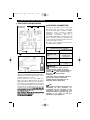
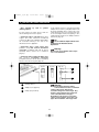
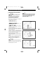
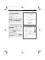
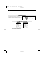
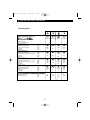
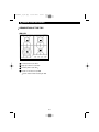
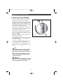
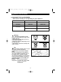
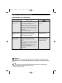
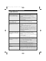
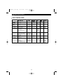
1
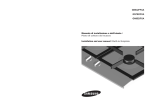
99640621_A_ML.qxp
IT
SV
EN
06/09/2006
09:46
Page 1
MANUALE PER L'INSTALLAZIONE E L'UTILIZZO
INSTALLATIONS- OCH ANVÄNDARMANUAL
GUIDE FOR INSTALLATION AND USE
Piano di cottura GN 642*/*
Spishäll GN 642*/*
Cooking Hob GN 642*/*
99640621_A_ML.qxp
06/09/2006
09:47
Page 38
TABLE OF CONTENTS
• Safety Recommendations ___________________________________ 39
• Environmental Protection ____________________________________ 40
• Description of Your Appliance ________________________________ 41
1 / INSTALLING YOUR APPLIANCE
• Proper Positioning _________________________________________
• Flush Mounting ____________________________________________
• Tips for Flush Mounting _____________________________________
• Electrical Connection _______________________________________
• Gas Connection ___________________________________________
• Changing the Gas Supply ___________________________________
42
42
43
43
44
46
2 / USING YOUR APPLIANCE
• Description of the top _______________________________________ 50
• Switching on gas burners ___________________________________ 51
• Cookware for gas burners ___________________________________ 52
3 / DAILY CARE OF YOUR APPLIANCE
• Maintaining your appliance __________________________________ 53
4 / SPECIAL MESSAGES, DIFFICULTIES
• During operation ___________________________________________ 54
5 / COOKING CHART
• Gas cooking guide _________________________________________ 55
6 / AFTER-SALES SERVICE DEPARTMENT AND CUSTOMER RELATIONS
• After Sales Service _________________________________________ 56
38
99640621_A_ML.qxp
06/09/2006
09:47
Page 39
SAFETY RECOMMENDATIONS
• SAFETY RECOMMENDATIONS
— We have designed this cooking hob for use
by private persons in their homes.
— All cooking should take place under your
surveillance.
— These cooking hobs are meant to be used
exclusively for cooking beverages and
foodstuffs and do not contain any asbestosbased materials.
— As part of our commitment to constantly
improving our products, we reserve the right
to make changes to them based on
technological advances to their technical,
functional and/or esthetic properties.
— Using a gas cooking appliance results in the
generation of heat and humidity in the
location where it is installed. Please ensure
that your kitchen has proper ventilation: keep
natural ventilation orifices open or install a
mechanical device (mechanical ventilation
hood).
— Intensive, prolonged use of the appliance
may require additional ventilation; you can, for
example, open a window or provide more
effective ventilation by increasing power to
the mechanical ventilation, if you have it.
— Do not store CLEANING products or
FLAMMABLE products (aerosol cans or
containers under pressure, as well as papers,
cookbooks, etc.) in the cabinet underneath
your cooking hob.
— If you use a drawer located under the hob,
we recommend that you avoid storing in it
items that are heat sensitive (plastic, papers,
aerosol cans, etc.).
— The conditions for adjusting the hob are
written on a sticker located in the plastic bag,
as well as on the packaging.
— In order to easily locate the reference
information for your appliance, we
recommend that you note them on the "AfterSales Service Department and Customer
Relations" page. (This page also explains to
you where to find this information on your
appliance).
— Your hob should be disconnected from
power and fuel supplies (electricity and gas)
before any repairs.
— When you connect the power cables of any
electrical appliances plugged in close to the
hob, ensure that they are not in contact with
the cooking zones.
— As a safety measure, do not forget after use
to close the general supply tap for gas
distributed by pipe or the tap of the tank for
butane or propane gas.
— When a knob becomes difficult to turn, DO
NOT FORCE IT. Request an emergency service
call for the installer.
— The CE compliance designation is affixed to
these hobs.
— This appliance must be installed in
compliance with currently applicable
regulations and used only in a well-ventilated
location.
Consult this guide before installing and using
your appliance.
• ENVIRONMENTAL PROTECTION
— The packing materials can be recycled.
— Dispose of them in containers provided for
this purpose based on their individual
recycling symbols.
— Used appliances should be disposed of in
compliance with the regulations in effect in
your place of residence.
Warning
Installation should only be performed
by installers and qualified technicians.
Before installation, ensure that the conditions of local distribution (gas type and
pressure) and the settings of the appliance
are compatible.
This hob complies with the EN 60335-2-6
standard with regard to the heating of cabinets and the Class 3 standard with regard
to installation (according to the EN 30-1-1
standard).
39
99640621_A_ML.qxp
06/09/2006
09:47
Page 40
RESPECT FOR THE ENVIRONMENT
• RESPECT FOR THE ENVIRONMENT
— This appliance's packaging material is recyclable. Help recycle it and protect the environment by dropping it off in the municipal
receptacles provided for this purpose.
— Your appliance also contains a
great amount of recyclable material. It is marked with this label to
indicate the used appliances that
should not be mixed with other
waste. This way, the appliance
recycling organised by your manufacturer will be done under the best possible
conditions, in compliance with European
Directive 2002/96/EC on Waste Electrical and
Electronic Equipment. Contact your town hall
or your retailer for the used appliance collection points closest to your home.
— We thank you doing your part to protect the
environment.
40
99640621_A_ML.qxp
06/09/2006
09:47
Page 41
SAFETY RECOMMENDATIONS
• DESCRIPTION OF YOUR HOB
Saucepan
support
grid
A
B
C
D
E
Fig. 01
F
G
H
A
Burner covers
D
Thermocouple
G
Gasket
B
Burner head
E
Injector
H
Tap
C
Spark plugs
F
Knob
Tip
This Guide to Installation and Use is valid for several models. Minor differences in details
and fittings may emerge between your appliance and the descriptions provided.
41
99640621_A_ML.qxp
06/09/2006
09:47
Page 42
70 cm
cm min
mini
1 / INSTALLING YOUR APPLIANCE
APPLIANCE
3300
ccm
m
i
minin
mm
ccm
5,.8
33 cm
mini
cmmin
m
mi
ini
56
cm
i
n
mini
mm
c
m
c
8
448
330
0cm
cm
mm
ini
ni
Width
Depth
Thickness
Total
dimensions
above
the work
top
58 cm
52.2 cm
4.9 cm
Total
dimensions
below
the work
toptravail
55.4 cm
47.4 cm
3.5 cm
Fig. 01
• PROPER POSITIONING
— To ensure a tight seal between the housing
and the work top, glue the foam seal along
the exterior edge of the housing before
installing the hob (Fig. 02).
Your appliance shoud be built in the surface of
a support cabinet that is a minimum of 3 cm
thick, made of a material that resists heat or
that is covered with such a material.
So as not to disturb movement of cooking
utensils, there should not be to the right or left
or back any obstacle within 30 cm of the hob.
If a horizontal divider wall is positioned under
the hob, it should be placed between 10 cm
and 15 cm away from the top of the work top.
In any event, do not store aerosol cans or
containers under pressure in any
compartment that may exist under the hob
(See "Safety Recommendations" chapter).
Housing
• FLUSH MOUNTING
Seal
Follow the diagram (Fig. 01).
— Remove the pan supports, the burner covers
and burner heads; noting their positions.
— Turn the hob over and carefully place it on
top of the opening in the cabinet so as not to
damage the knobs and spark plugs.
Fig. 02
42
99640621_A_ML.qxp
06/09/2006
09:47
Page 43
1 / INSTALLING YOUR APPLIANCE
• TIPS FOR FLUSH MOUNTING
Underside view
A
• ELECTRICAL CONNECTION
A
Your hob is sold with a power cable (type
H05V2V2F - T90, cross-section 1 mm²) with
three conductors (phase + ground + neutral).
After-sales service reference: 77X3767
(6470.1516). It must be connected to a
220-240 V~ monophase grid via a
standardised CEI 60083 electrical outlet with
phase + ground + neutral or or an all-pole cutoff device with a minimum distance between
contact openings of 3.5 mm.
The plug of the electrical outlet must be
accessible after installation.
of the housing
CABLE CROSS-SECTION TO BE USED
Fig. 01
A
A
220-240 V~ 50 Hz
A
Mounting brackets
H05V2V2F - T90
cable
Cross-section of
conductors in mm²
Fuse
3 conductors,
including one
ground wire
1
10 A
Warning
Fig. 02
The safety wire (green-yellow) is
connected to the appliance's ground
terminal
and must be connected to the
ground lead
of the electrical set-up.
The fuse in your set-up must be
10 amperes.
If the power cable is damaged, it must be
replaced by a cable or a special kit
available from the manufacturer or its
After-Sales Service Department.
Mounting brackets
Place your hob in the opening of the support
cabinet, carefully pulling the table toward you.
Reposition the burner heads, burner covers
and pan supports on the hob.
Connect your hob to the gas supply (See
"Gas Connection" chapter) and to the power
supply (See "Electrical Connection" chapter).
If you wish, you can immobilise the hob using
the four mounting brackets delivered with a
screw (Fig. 02) to attach them to the four
corners of the housing. You must use the
holes provided for this purpose, according to
the diagram above (Fig. 01).
Stop screwing when the mounting bracket
starts to become deformed.
Do not use a screwdriver.
Tip
In order to easily locate the reference
information for your appliance, we
recommend that you note them on the
"After-Sales Service Department and
Customer Relations" page (this page also
explains to you where to find this
information on your appliance).
43
99640621_A_ML.qxp
06/09/2006
09:47
Page 44
1 / INSTALLING YOUR APPLIANCE
• GAS CONNECTION
• Preliminary comments
If your hob is installed above an oven or if proximity to other heating elements poses a threat of
overheating the connection, you absolutely must insulate the cable in a rigid pipe.
If a hose or soft pipe (in the case of butane gas) is used, it should not come into contact with a
moving part of the cabinet, nor should it pass through a location that may become blocked.
The gas connection must be installed in
compliance with applicable regulations in the
country of installation.
• Gas distributed by pipe; natural gas
For your safety, you must choose from the
three following connection options:
— Connection with a rigid pipe made from
copper and with screw-on mechanical
connectors (G1/2 gas standard mark) Make
the connection directly to the end of the
elbow fitted on the appliance.
— Connection with a wavy metal hose
(stainless steel) with screw-on mechanical
connectors (compliant with NF D 36-121
standard) whose service life is unlimited
(Fig. A).
Q;@
Q;@
— Connection with a reinforced rubber hose
with screw-on mechanical connectors
(compliant with the NF D 36-103 standard)
whose service life is 10 years (Fig. B).
Warning
When connecting your hob's gas
supply, if you have to change the
direction of the elbow fitted on the
appliance:
① Change the gasket.
② Screw on the elbow's nut, careful not
to exceed a torque of 17 N.m.
Fig. A
44
Fig. B
99640621_A_ML.qxp
06/09/2006
09:47
Page 45
1 / INSTALLING YOUR APPLIANCE
• Gas supplied by tank or cylinder
(butane/propane)
In an existing system, a soft pipe fitted with
clamps whose service (compliant with the XP
D 36-110 standard) whose service life is five
years may be used. It is necessary in this case
to use an adaptor without forgetting to fit a
sealing washer between the adaptor and the
hob's bent (Fig. 03).
For your safety, you must choose from the
three following connection options:
— Connection with a rigid pipe made from
copper and with screw-on mechanical
connectors (G1/2 gas standard mark). Make
the connection directly to the end of the
elbow fitted on the appliance
Tip
You can obtain the adaptor and the sealer
washer from your After-Sales Service
Department.
— Connection with a wavy metal hose
(stainless steel) with screw-on mechanical
connectors (compliant with NF D 36-125
standard) whose service life is unlimited
(Fig. 01).
Warning
Screw on the adaptor with a torque
not to exceed 25 N.m.
— Connection with a reinforced rubber hose
with screw-on mechanical connectors
(compliant with the XP D 36-112 standard)
whose service life is 10 years (Fig. 02).
Fig. 01
Fig. 02
Fig. 03
A
B
C
A
Sealing washer
B
Adaptor (not supplied)
C
Clamp (not provided)
Warning
All soft pipes and hoses whose
service life is limited must have a maximum
length of two meters and must be
accessible along their entire length. They
must be replaced before the end of their
service life (indicated on the pipe).
Regardless of the means of connection
chosen, ensure that the connection is air
tight, after installation, with soapy water.
45
99640621_A_ML.qxp
06/09/2006
09:47
Page 46
1 / INSTALLING YOUR APPLIANCE
• CHANGING THE GAS SUPPLY
Tip
Each time you change the gas supply,
tick the box corresponding to the new gas
level on the label found in the plastic bag.
Refer to the corresponding "Gas
Connection" section.
Warning
Your appliance is sold pre-set for
natural gas.
The injectors required for adaption to
butane/propane can be found in the
plastic bag containing this guide.
Each time you change the gas supply, you
must complete the following:
— Adapt the gas connection
— Change the injectors
— Adjust the hob connections
Wrench
• Adapt the gas connection: Refer to the
"Gas Connection" section.
• Change the injectors, proceeding as
follows:
— Remove the pan supports, heads and
covers from all burners.
— Using the wrench provided, unscrew the
injectors located under each crucible and
remove them (Fig. 01).
— Replace with the corresponding gas
injectors, in compliance with the placement of
the injectors and the table of gas properties at
the end of this section; to do this:
— First screw them in manually until the
injector locks into place.
— Apply the wrench to the injector as far as it
will go.
— Draw a line on the burner plate using a
pencil at the place indicated (Fig. 02).
— Turn the wrench clockwise until the line
appears on the other side (Fig. 03).
Fig. 01
Crucible
Injector
Line
Wrench
Fig. 02
Warning
Exceeding this limit may damage the
product.
Line
- Reposition the burner heads, burner covers
and pan supports on the hob.
Wrench
Fig. 03
46
99640621_A_ML.qxp
06/09/2006
09:47
Page 47
1 / INSTALLING YOUR APPLIANCE
• Adjust the hob connections: they are
located underneath the knobs (Fig. 04).
— Proceed one tap at a time.
— Remove the knobs and the gaskets by
pulling them up.
- Switching
from
butane/propane
natural
gas
Knob
to
- With a small flat-head screwdriver, screw in
all the way the brass (yellow) burner power
screws (Fig. 05), in a clockwise direction.
- Replace the gaskets and the knobs, paying
careful attention to their direction and
ensuring that the knobs are pushed in all the
way.
Gasket
Tap
Fig. 04
— Switching from butane/propane to natural
- Unscrew the brass (yellow) burner power
screws (Fig. 05), using a small flat-head
screwdriver, by turning two times
counterclockwise.
- Replace the knob,
- Light the burner in maximum heat mode,
then turn down to reduced heat mode.
- Remove the knob again, then turn the burner
power screws clockwise until it reaches the
lowest possible setting that does not
extinguish the flame.
- Replace the gasket and knob.
- Make several attempts to shift from the
maximum flow rate to the minimum: the flame
should not go out; if it does, unscrew the
burner power screw so as to obtain good
flame retention during these position
switches.
Burner power
adjustment screw
Tap axis
Fig. 05
47
99640621_A_ML.qxp
06/09/2006
09:47
Page 48
1 / INSTALLING YOUR APPLIANCE
• Markings on the injectors
MARKINGS ON THE INJECTORS
The adjacent table shows where the injectors are
positioned on your appliance according to the type of gas
Each number is marked on the injector.used.
Example:
Injector marking 94
Four-burner gas model with double crown burner *
Butane/Propane Gas
Natural Gas
94
121
62
78
147
63
95
50
* See "Description of the Top" chapter
48
99640621_A_ML.qxp
06/09/2006
09:47
Page 49
1 / INSTALLING YOUR APPLIANCE
•Gas Properties
IT
GB
Applicance intended to be installed in:
GB - IT ........................ cat: II2H3+
SE ............................... cat: II2H3 B/P
Hourly rate below:
At 15° C under 1013 mbar
HIGH-SPEED BURNER
Marking engraved on injector
Nominal heat release rate
Reduced heat release rate
Hourly rate
Hourly rate
DOUBLE CROWN BURNER
Marking engraved on injector
Nominal heat release rate
Reduced heat release rate (with safety)
Hourly rate
Hourly rate
SEMI-FAST BURNER
Marking engraved on inector
Nominal heat release rate
Reduced heat release rate (with safety)
Hourly rate
Hourly rate
IT
GB
Butane
Propane
G30
28-30 mbar
G31
37 mbar
78
2,25
0,850
164
78
2,25
(kW)
(kW)
(g/h)
(l/h)
IT
SE
GB
Natural
gas
G20
20 mbar
121
2,25
0,850
161
SE
Butane
G30
30 mbar
78
2,25
0,850
164
214
95
3,50
1,450
254
(kW)
(kW)
(g/h)
(l/h)
95
3,50
147
3,80
1,400
250
95
3,50
1,450
254
362
62
1,45
0,700
105
(kW)
(kW)
(g/h)
(l/h
62
1,45
94
1,50
0,650
104
62
1,45
0,700
105
143
AUXILIARY BURNER
Marking engraved on injector
Nominal heat release rate
Reduced heat release rate
Hourly rate
Hourly rate
50
0,900
0,350
65
(kW)
(kW)
(g/h)
(l/h)
50
0,900
63
0,850
0,300
64
50
0,900
0,350
65
81
HOB, 60 cm, FOUR-BURNER GAS MODEL WITH DOUBLE CROWN BURNER
Total heat release rate
(kW)
Maximum flow rate
(g/h
(l/h)
49
8,10
588
8,10
579
8,40
800
8,10
588
99640621_A_ML.qxp
06/09/2006
09:47
Page 50
2 / USING YOUR APPLIANCE
• DESCRIPTION OF THE TOP
GN 642*
A
B
C
D
A
Semi-fast burner1,50 kW**
B
High-speed burner 2,25 kW**
C
Auxiliary burner 0,85 kW**
D
Double crown burner 3,8 kW**
* Power obtained with natural gas G20
50
99640621_A_ML.qxp
06/09/2006
09:48
Page 51
2 / USING YOUR APPLIANCE
• SWITCHING ON GAS BURNERS
The burner safety measure is a metal rod
located directly to the side of the flame.
Each burner is controlled by a tap fitted with
a safety system that, in the event of accidental flame extinction (spills, draughts, etc.),
quickly and automatically cuts the gas supply
and prevents it from being released.
Each burner is supplied by a tap that is
opened when you press in the knob and turn
it in a counterclockwise direction.
The “ ” point corresponds to a closed tap.
— Select the desired burner by referring to the
symbols located near the knobs (e.g. front
right burner
).
Your hob is fitted with a burner-lighting system built into the knobs.
— To light a burner, press on the knob and turn
it in a counterclockwise direction
to the
maximum setting .
o
Fig. 01
— Continue to press on the knob to produce a
series of sparks until the burner lights.
The setting for more moderate flame intensities are between the
symbol and the
symbol.
Tip
In order to ensure the proper lighting
of the double crown burner, we suggest
that you light it before placing cookware on
it.
When a knob becomes difficult to turn, do
not force it. Request an emergency service
call from the installer.
Warning
Hold the knob completely pressed
down for a few seconds after the flame
appears to trigger the safety system.
51
99640621_A_ML.qxp
06/09/2006
09:48
Page 52
2 / USING YOUR APPLIANCE
• COOKWARE FOR GAS BURNERS
• Which burner should you use depending on your cookware?
Diameter of the cookware
Burner
20 to 30 cm
Double crown
16 to 28 cm
High-speed
Searing foods
Semi-fast
Sauces - Reheating
Auxiliary
Gentle simmer
Use
12 to 24 cm
Warning
— Adjust the ring of flames so that
they do not extend beyond the edges of the
cookware (Fig. 01).
— Do not use cookware with a concave or
convex bottom (Fig. 02).
— Do not use cookware that partially covers
the knobs (Fig. 03).
— Do not leave a gas burner operating with
empty cookware.
GOOD
BAD
CONVEX
CONCAVE
Fig. 01
Tip
Fig. 02
Keep natural ventilation orifices in your
home open or install a mechanical
ventilation device (mechanical ventilation
hood).
Intensive, prolonged use of the appliance
may require additional ventilation; you can,
for example, open a window or provide
more effective ventilation or increase power
to the mechanical ventilation, if you have it
(a minimum air flow of 2 m3 per kW of gas
power is required).
Example:
60 cm - Four gas burners
Total power: 1.5 + 2.25 + 3.8 + 0.85 = 8.4kW
8.4 kW x 2 = 16.8 m3/h
minimum flow.
Fig. 03
52
99640621_A_ML.qxp
06/09/2006
09:48
Page 53
3 / DAILY CARE OF YOUR APPLIANCE
• MAINTAINING YOUR APPLIANCE
MAINTENANCE...
Of the spark plugs
and injectors
PRODUCTS/ACCESSORIES
TO USE
In the event that the spark plugs become . Small, hard-bristled brush.
. Safety pin
soiled, clean them using a small, hardbristled brush (non-metallic).
The gas injector is located in the centre
of the burner in the shape of a dish. Be
careful not to obstruct it during cleaning,
as this will undermine the performance
of your hob.
In the event of obstruction, use a safety
pin to unclog the injector.
WHAT TO DO
. Gentle scrubbing cream
. Disinfectant sponge
Of the pan
supports and gas
burners
If tough stains occur, use a non-abrasive
cream, then rinse with clean water.
Carefully wipe each part of the burner
before using your hob again.
Of the enamel or
stainless steel
. Gentle scrubbing cream
To clean the hob's enamel, use a
. Commercially available
scrubbing cream. Polish it with a dry
specialised product
cloth.
Do not allow acidic liquids such as lemon
juice, vinegar, etc. to remain in contact
with the enamel.
To clean the hob's stainless steel, use a
sponge and soapy water or a
commercially available special stainless
steel product.
Warning
It will be easier to maintain your hob if you clean it before it has completely cooled
down. However, never clean your appliance while it is in operation. Set all the gas controls
to zero.
Tip
— It is better to clean the parts of the hob by hand rather than in the dishwasher.
— Do not use an abrasive sponge to clean your hob.
— Do not use steam cleaning.
53
99640621_A_ML.qxp
06/09/2006
09:48
Page 54
4 / SPECIAL MESSAGES, DIFFICULTIES
• DURING OPERATION
YOU OBSERVE THAT
• Lighting the burners:
There is no spark when you
press on the knobs or button.
• When you press on a knob,
there are sparks on all of the
burners simultaneously.
• There are sparks, but the
burner (burners) does (do) not
light.
• If the hob has a gas safety:
during lighting, the flames light,
then go out as soon as the knob
is released
• In reduced heat mode, the
burner goes out or the flames
remain high.
• The flames look irregular or
uneven.
• During cooking, the knobs
become hot.
WHAT SHOULD YOU DO:
. Check the electrical connection of your appliance
. Check that the spark plugs are clean
. Check that the burners are clean and properly
assembled
. If the hob is attached to the work top, check that the
mounting brackets are not deformed.
. Check that the gaskets under the knobs are not coming
out of their lodging.
This is normal. The lighting function is centralised and
controls all of the burners simultaneously.
. Check that the gas inlet pipe is not pinched.
. Check that the length of the gas inlet pipe is less than
two meters.
. Check that the gas inlet pipe is open.
. If you have gas in a cylinder or tank, check that it is not
empty.
. If you have just installed the hob or changed the gas
cylinder, hold the knob down in maximum open position
until gas arrives in the burners.
. Check that the injector is not clogged; if it is, unclog it
with a safety pin.
. Press firmly down on the knobs and hold them down for
a few seconds after the appearance of flames.
. Check that the parts of the burner are correctly
mounted.
. Check that the gaskets under the knobs are not coming
out of their lodging.
. Avoid strong draughts in the room.
. Light your burner before placing your saucepan on it.
. Avoid strong draughts in the room.
. Check that the gas type being used corresponds to the
injectors installed (Read about markings on the injectors
in the "Changing the Gas Supply" chapter).
Reminder: The cooking hobs are sold pre-set for use with
network gas (natural gas).
. Check that the burner power screws are properly set
(See the "Changing the Gas Supply" chapter).
. Check the cleanliness of the burners and injectors under
the burners, the assembly of the burners, etc.
. Use small saucepans on the burners located closest to
the knobs. Larger saucepans should be placed on the
largest burners, those that are furthest from the knobs.
. Properly place the saucepan in the centre of the burner.
54
99640621_A_ML.qxp
06/09/2006
09:48
Page 55
5 / COOKING CHART
• GAS COOKING GUIDE
PREPARATIONS
TIMES
DOUBLE
CROWN
SOUPS
Bouillons
Thick soups
8-10 minutes
X
FISH
Court-bouillon
Barbecue
8-10 minutes
8-10 minutes
X
SAUCES
Hollandaise, béarnaise
Béchamel, aurore
VEGETABLES Endives, spinach
Cooked peas
Provençal tomatoes
Golden brown potatoes
Pasta
MEATS
Steak
Blanquette, Osso-bucco
Sauteed poultry breasts
Tournedos
FRYING
French fries
Beignets
DESSERTS
Rice pudding
Fruit compote
Crêpes
Chocolate
Crème anglaise
Coffee (small percolator)
FAST
SEMIFAST
AUXILIARY
X
10 minutes
X
X
X
X
X
X
X
X
X
X
X
25-30 minutes
15-20 minutes
X
X
90 minutes
10-12 minutes
10 minutes
X
X
X
25 minutes
X
3-4 minutes
3-4 minutes
10 minutes
X
X
X
55
99640621_A_ML.qxp
06/09/2006
09:48
Page 56
Per qualsiasi domanda o commento sui prodotti SAMSUNG, rivolgersi al centro post-vendita SAMSUNG,
800.31.42.78
www.samsung.com/it
SV
Kontakta kundtjänst på SAMSUNG Om du har några frågor eller
kommentarer som har att göra med produkter från SAMSUNG,
08.585.367.87
www.samsung.com/se
EN
If you have any questions or comments relating to SAMSUNG
products, please contact the SAMSUNG customer care centre,
0870.242.0303
www.samsung.com/uk
9964-0621 - 09/06
GN642*/*
56
Brandt Appliances - a simplified joint stock company with a capital of 10,000,000 euros, Nanterre Trade and Companies Register no. 440 302 347.
IT
9964-0621 - 09/06 - Translatp, Agency TECHNICIS
6 / AFTER SALES SERVICE