1
Command Line Tools
User Guide
(Formerly the Development System Reference Guide)
UG628 (v14.7) October 2, 2013
Notice of Disclaimer
The information disclosed to you hereunder (the "Materials") is provided solely for the selection and use
of Xilinx products. To the maximum extent permitted by applicable law: (1) Materials are made available
"AS IS" and with all faults, Xilinx hereby DISCLAIMS ALL WARRANTIES AND CONDITIONS, EXPRESS,
IMPLIED, OR STATUTORY, INCLUDING BUT NOT LIMITED TO WARRANTIES OF MERCHANTABILITY,
NON-INFRINGEMENT, OR FITNESS FOR ANY PARTICULAR PURPOSE; and (2) Xilinx shall not be liable
(whether in contract or tort, including negligence, or under any other theory of liability) for any loss or damage
of any kind or nature related to, arising under, or in connection with, the Materials (including your use of the
Materials), including for any direct, indirect, special, incidental, or consequential loss or damage (including loss
of data, profits, goodwill, or any type of loss or damage suffered as a result of any action brought by a third
party) even if such damage or loss was reasonably foreseeable or Xilinx had been advised of the possibility of the
same. Xilinx assumes no obligation to correct any errors contained in the Materials or to notify you of updates to
the Materials or to product specifications. You may not reproduce, modify, distribute, or publicly display the
Materials without prior written consent. Certain products are subject to the terms and conditions of the Limited
Warranties which can be viewed at http://www.xilinx.com/warranty.htm; IP cores may be subject to warranty
and support terms contained in a license issued to you by Xilinx. Xilinx products are not designed or intended to
be fail-safe or for use in any application requiring fail-safe performance; you assume sole risk and liability for use
of Xilinx products in Critical Applications: http://www.xilinx.com/warranty.htm#critapps.
© Copyright 2002-2013 Xilinx Inc. All rights reserved. Xilinx, the Xilinx logo, Artix, ISE, Kintex, Spartan, Virtex,
Vivado, Zynq, and other designated brands included herein are trademarks of Xilinx in the United States and
other countries. The PowerPC name and logo are registered trademarks of IBM Corp., and used under license.
All other trademarks are the property of their respective owners.
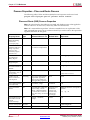
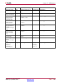
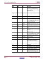
Revision History
The following table shows the revision history for this document.
Date
Version
03/01/2011
13.1 download
Adding information for Xilinx® 7 series FPGA devices.
03/02/2011
13.1 Web release
Additional updates for Xilinx 7 series FPGA devices.
07/06/2011
13.2 download
Updated information on Xilinx 7 series FPGA supported devices (CR #610690 and
edit requests)
Updated all Processes and Properties tables to match the GUI. Added Static Timing
Process Properties table based on GUI
Additional detail to Tclk set_family option (CR #604108)
Added USR_ACCESS option to BitGen chapter (edit request)
Removed CLT documentation options that are obsoleted by change to map
-global_opt flow (CR #604740)
Misc. other corrections to match document with how the software works (CR
#590750, #593738, #594127, #595446, #596310, #596916, #604740, #609259)
10/19/2011
13.3 download
Documented bitgen options RevisionSelect and RevisionSelect_tristate
Added Tcl command information for RevisionSelect and RevisionSelect_tristate
Updated BitGen flow diagram to include all current input and output files
Final characterization for bitgen -g ConfigRate for 7 series devices
Added links from Bitgen options table to options
2
www.xilinx.com
Command Line Tools User Guide
UG628 (v14.7) October 2, 2013
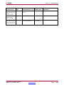
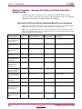
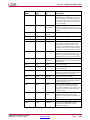
Date
Version
1/18/2012
13.4 download
Reorganized SmartXplorer chapter to better expose how to run strategies in parallel
Add bitgen -g next_config_reboot option
par -activityfile switch is not supported in newer architectures
4/24/2012
14.1 Web release
Adding information for Zynq FPGA device support.
7/25/2012
14.2 Web release
CR fixes for the 14.2 release. Some additions to bitgen -g. Add XPWR -vid option.
10/2/2013
14.7 Web release
Fixed CR #681576 (incorrect list of supported architectures for Utilization by
Hierarchy). Minor editorial updates elsewhere.
Command Line Tools User Guide
UG628 (v14.7) October 2, 2013
Send Feedback
www.xilinx.com
3
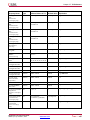
Table of Contents
Revision History .................................................................................................... 2
Chapter 1
Introduction .................................................................................................9
Command Line Program Overview ...................................................................... 9
Command Line Syntax......................................................................................... 10
Command Line Options ...................................................................................... 10
Invoking Command Line Programs.................................................................... 14
Chapter 2
Design Flow...............................................................................................15
Design Flow Overview ........................................................................................ 15
Design Entry and Synthesis ................................................................................ 18
Design Implementation....................................................................................... 22
Design Verification............................................................................................... 25
FPGA Design Tips ............................................................................................... 31
Chapter 3
PARTGen ...................................................................................................33
PARTGen Overview............................................................................................. 33
PARTGen Syntax.................................................................................................. 39
PARTGen Command Line Options..................................................................... 39
Chapter 4
NetGen .......................................................................................................43
NetGen Overview ................................................................................................ 43
NetGen Simulation Flow..................................................................................... 45
NetGen Equivalence Checking Flow.................................................................. 55
NetGen Static Timing Analysis Flow ................................................................. 59
Preserving and Writing Hierarchy Files ............................................................. 63
Dedicated Global Signals in Back-Annotation Simulation .............................. 65
Chapter 5
Logical Design Rule Check (DRC)...........................................................67
Logical DRC Overview ........................................................................................ 67
Logical DRC Checks ............................................................................................ 67
Chapter 6
NGDBuild ...................................................................................................71
NGDBuild Overview ........................................................................................... 71
NGDBuild Syntax ................................................................................................ 74
NGDBuild Options.............................................................................................. 74
Chapter 7
MAP............................................................................................................81
MAP Overview..................................................................................................... 81
Send Feedback
4
www.xilinx.com
Command Line Tools User Guide
UG628 (v14.7) October 2, 2013
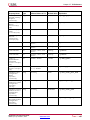
MAP Process......................................................................................................... 83
MAP Syntax.......................................................................................................... 84
MAP Options........................................................................................................ 86
Resynthesis and Physical Synthesis Optimizations .......................................... 97
Guided Mapping.................................................................................................. 97
Simulating Map Results ...................................................................................... 98
MAP Report (MRP) File....................................................................................... 99
Physical Synthesis Report (PSR) File................................................................ 105
Halting MAP ...................................................................................................... 107
Chapter 8
Physical Design Rule Check..................................................................109
DRC Overview ................................................................................................... 109
DRC Syntax ........................................................................................................ 109
DRC Options ...................................................................................................... 110
DRC Checks ....................................................................................................... 111
DRC Errors and Warnings ................................................................................. 111
Chapter 9
Place and Route (PAR) ...........................................................................113
PAR Overview .................................................................................................... 113
PAR Process ........................................................................................................ 115
PAR Syntax ......................................................................................................... 116
Detailed Listing of Options............................................................................... 117
PAR Reports ....................................................................................................... 123
ReportGen .......................................................................................................... 131
Halting PAR........................................................................................................ 133
Chapter 10
SmartXplorer .........................................................................................135
Overview ............................................................................................................ 135
General Usage .................................................................................................... 135
Using Strategies ................................................................................................. 138
Running Strategies in Parallel .......................................................................... 145
Reports................................................................................................................ 149
Command Line Reference ................................................................................. 152
Chapter 11
XPWR .....................................................................................................165
XPWR Overview ................................................................................................ 165
XPWR Syntax...................................................................................................... 166
XPWR Command Line Options ........................................................................ 167
XPWR Command Line Examples ...................................................................... 170
Using XPWR ....................................................................................................... 170
Command Line Tools User Guide
UG628 (v14.7) October 2, 2013
Send Feedback
www.xilinx.com
5
Power Reports .................................................................................................... 171
Chapter 12
PIN2UCF ................................................................................................173
PIN2UCF Overview ........................................................................................... 173
PIN2UCF Syntax ................................................................................................ 176
PIN2UCF Command Line Options ................................................................... 177
Chapter 13
TRACE....................................................................................................179
TRACE Overview............................................................................................... 179
TRACE Syntax.................................................................................................... 180
TRACE Options ................................................................................................. 181
TRACE Command Line Examples .................................................................... 186
TRACE Reports .................................................................................................. 186
OFFSET Constraints........................................................................................... 202
PERIOD Constraints .......................................................................................... 210
Halting TRACE .................................................................................................. 214
Chapter 14
Speedprint .............................................................................................215
Speedprint Overview......................................................................................... 215
Speedprint Command Line Syntax ................................................................... 219
Speedprint Command Line Options................................................................. 219
Chapter 15
BitGen ....................................................................................................221
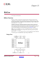
BitGen Overview ............................................................................................... 221
BitGen Command Line Syntax.......................................................................... 223
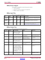
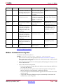
BitGen Command Line Options ....................................................................... 224
Chapter 16
BSDLAnno .............................................................................................253
BSDLAnno Overview ........................................................................................ 253
BSDLAnno Command Line Syntax .................................................................. 254
BSDLAnno Command Line Options ................................................................ 254
BSDLAnno File Composition ........................................................................... 255
Boundary Scan Behavior in Xilinx Devices ...................................................... 261
Chapter 17
PROMGen ..............................................................................................263
PROMGen Overview......................................................................................... 263
PROMGen Syntax.............................................................................................. 264
PROMGen Options............................................................................................ 265
Bit Swapping in PROM Files ............................................................................ 271
PROMGen Examples ......................................................................................... 271
Send Feedback
6
www.xilinx.com
Command Line Tools User Guide
UG628 (v14.7) October 2, 2013
Chapter 18
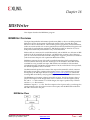
IBISWriter ..............................................................................................273
IBISWriter Overview ......................................................................................... 273
IBISWriter Syntax .............................................................................................. 274
IBISWriter Options ............................................................................................ 275
Chapter 19
CPLDFit..................................................................................................277
CPLDFit Overview............................................................................................. 277
CPLDFit Syntax .................................................................................................. 278
CPLDFit Options................................................................................................ 279
Chapter 20
TSIM .......................................................................................................287
TSIM Overview.................................................................................................. 287
TSIM Syntax....................................................................................................... 287
Chapter 21
TAEngine ...............................................................................................289
TAEngine Overview........................................................................................... 289
TAEngine Syntax................................................................................................ 290
TAEngine Options.............................................................................................. 290
Chapter 22
Hprep6 ...................................................................................................291
Hprep6 Overview............................................................................................... 291
Hprep6 Options.................................................................................................. 292
Chapter 23
XFLOW ...................................................................................................295
XFLOW Overview .............................................................................................. 295
XFLOW Syntax ................................................................................................... 299
XFLOW Flow Types ........................................................................................... 300
Flow Files............................................................................................................ 305
XFLOW Option Files.......................................................................................... 307
XFLOW Options................................................................................................. 309
Running XFLOW................................................................................................ 313
Chapter 24
NGCBuild ...............................................................................................315
NGCBuild Overview ......................................................................................... 315
NGCBuild Syntax .............................................................................................. 316
NGCBuild Options ............................................................................................ 317
Chapter 25
Compxlib ...............................................................................................323
Compxlib Overview........................................................................................... 323
Compxlib Syntax................................................................................................ 324
Compxlib Options.............................................................................................. 325
Compxlib Command Line Examples ................................................................ 330
Command Line Tools User Guide
UG628 (v14.7) October 2, 2013
Send Feedback
www.xilinx.com
7
Specifying Runtime Options............................................................................. 331
Sample Configuration File (Windows Version) ............................................... 334
Chapter 26
XWebTalk ...............................................................................................339
WebTalk Overview............................................................................................. 339
XWebTalk Syntax ............................................................................................... 340
XWebTalk Options ............................................................................................. 340
Chapter 27
Tcl Reference ........................................................................................343
Tcl Overview....................................................................................................... 343
Tcl Fundamentals ............................................................................................... 344
Project and Process Properties........................................................................... 346
Xilinx Tcl Commands for General Use ............................................................. 365
Xilinx Tcl Commands for Advanced Scripting................................................. 382
Example Tcl Scripts ............................................................................................ 397
Appendix A ISE Design Suite Files.........................................................................403
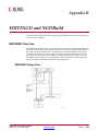
Appendix B EDIF2NGD and NGDBuild ...................................................................409
EDIF2NGD Overview........................................................................................ 409
EDIF2NGD Options........................................................................................... 411
NGDBuild .......................................................................................................... 413
Appendix C Additional Resources..........................................................................423
Send Feedback
8
www.xilinx.com
Command Line Tools User Guide
UG628 (v14.7) October 2, 2013
Chapter 1
Introduction
This chapter describes the command line programs for the ISE® Design Suite. This
guide was formerly known as the Development System Reference Guide, but has been
renamed to Command Line Tools User Guide.
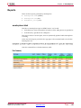
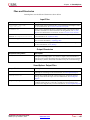
Command Line Program Overview
Xilinx® software command line programs allow you to implement and verify your
design. The following table lists the programs you can use for each step in the design
flow. For detailed information, see the Design Flow chapter in this guide.
Command Line Programs in the Design Flow
Design Flow Step
Command Line Program
Design Implementation
NGDBuild, MAP, PAR, SmartXplorer, BitGen
Timing-driven Placement and Routing,
Re-synthesis, & Physical Synthesis
Optimizations
MAP
Timing Simulation and Back Annotation
(Design Verification)
NetGen
Static Timing Analysis
(Design Verification)
TRACE
Note MAP uses specified options to enable
timing-driven placement and routing
(-timing), and re-synthesis and physical
synthesis optimizations that can transform a
design to meet timing requirements.
You can run these programs in the standard design flow or use special options to run the
programs for design preservation. Each command line program has multiple options,
which allow you to control how a program executes. For example, you can set options to
change output file names, to set a part number for your design, or to specify files to read
in when executing the program. You can also use options to create guide files and run
guide mode to maintain the performance of a previously implemented design.
Some of the command line programs described in this guide underlie many of the
Xilinx Graphical User Interfaces (GUIs). The GUIs can be used with the command
line programs or alone. For information on the GUIs, see the online Help provided
with each Xilinx tool.
Command Line Tools User Guide
UG628 (v14.7) October 2, 2013
Send Feedback
www.xilinx.com
9
Chapter 1: Introduction
Command Line Syntax
Command line syntax always begins with the command line program name. The
program name is followed by any options and then by file names. Use the following
rules when specifying command line options:
•
Enter options in any order, preceded them with a dash (minus sign on the keyboard)
and separate them with spaces.
•
Be consistent with upper case and lower case.
•
When an option requires a parameter, separate the parameter from the option by
spaces or tabs. For example, the following shows the command line syntax for
running PAR with the effort level set to high:
•
•
–
Correct: par -ol high
–
Incorrect: par -olhigh
When using options that can be specified multiple times, precede each parameter
with the option letter. In this example, the -l option shows the list of libraries to
search:
–
Correct: -l xilinxun -l synopsys
–
Incorrect: -l xilinxun synopsys
Enter parameters that are bound to an option after the option.
–
Correct: -f command_file
–
Incorrect: command_file -f
Use the following rules when specifying file names:
•
•
Enter file names in the order specified in the chapter that describes the command
line program. In this example the correct order is program, input file, output file,
and then physical constraints file.
–
Correct: par input.ncd output.ncd freq.pcf
–
Incorrect: par input.ncd freq.pcf output.ncd
Use lower case for all file extensions (for example, .ncd).
Command Line Options
The following options are common to many of the command line programs provided
with the ISE® Design Suite.
•
-f (Execute Commands File)
•
-h (Help)
•
-intstyle (Integration Style)
•
-p (Part Number)
-f (Execute Commands File)
With any Xilinx® command line program for use with FPGA designs, you can store
command line program options and file names in a command file. You can then execute
the arguments by entering the program name with the -f option followed by the name
of the command file. This is useful if you frequently execute the same arguments each
time you execute a program or if the command line command becomes too long.
Syntax
-f command_file
Send Feedback
10
www.xilinx.com
Command Line Tools User Guide
UG628 (v14.7) October 2, 2013
Chapter 1: Introduction
You can use the file in the following ways:
•
To supply all of the command options and file names for the program, as in the
following example:
par -f command_file
command_file is the name of the file that contains the command options and file
names.
•
To insert certain command options and file names within the command line, as in
the following example:
par -f placeoptions -f routeoptions design_i .ncd design_o .ncd
–
placeoptions is the name of a file containing placement command parameters.
–
routeoptions is the name of a file containing routing command parameters.
You create the command file in ASCII format. Use the following rules when creating
the command file:
•
Separate program options and file names with spaces.
•
Precede comments with the pound sign (#).
•
Put new lines or tabs anywhere white space is allowed on the Linux or DOS
command line.
•
Put all arguments on the same line, one argument per line, or a combination of these.
•
All carriage returns and other non-printable characters are treated as spaces and
ignored.
•
No line length limitation exists within the file.
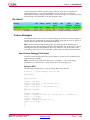
Example
Following is an example of a command file:
#command line options for par for design mine.ncd
-w
0l 5
/home/yourname/designs/xilinx/mine.ncd
#directory for output designs
/home/yourname/designs/xilinx/output.dir
#use timing constraints file
/home/yourname/designs/xilinx/mine.pcf
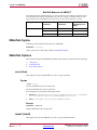
-h (Help)
When you enter the program name followed by this option, you will get a message
listing all options for the program and their parameters, as well as the file types used by
the program. The message also explains each of the options.
Syntax
-h
-help
Command Line Tools User Guide
UG628 (v14.7) October 2, 2013
Send Feedback
www.xilinx.com
11
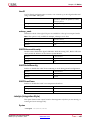
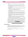
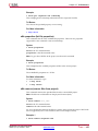
Chapter 1: Introduction
Symbol
Description
[]
Encloses items that are optional.
{}
Encloses items that may be repeated.
italics
Indicates a variable name or number for which
you must substitute information.
,
Shows a range for an integer variable.
-
Shows the start of an option name.
:
Binds a variable name to a range.
|
Logical OR to show a choice of one out of
many items. The OR operator may only
separate logical groups or literal keywords.
()
Encloses a logical grouping for a choice
between sub-formats.
Example
Following are examples of syntax used for file names:
•
infile[.ncd] shows that typing the .ncd extension is optional but that the extension
must be .ncd.
•
infile.edn shows that the .edn extension is optional and is appended only if there
is no other extension in the file name.
For architecture-specific programs, such as BitGen, you can enter the following to get a
verbose help message for the specified architecture:
program_name -h architecture_name
You can redirect the help message to a file to read later or to print out by entering the
following:
program_name -h > filename
On the Linux command line, enter the following to redirect the help message to a file
and return to the command prompt.
program_name -h > & filename
-intstyle (Integration Style)
This option limits screen output, based on the integration style that you are running, to
warning and error messages only.
Syntax
-intstyle ise|xflow|silent
When using -intstyle, one of three modes must be specified:
•
-intstyle ise indicates the program is being run as part of an integrated design
environment.
•
-intstyle xflow indicates the program is being run as part of an integrated
batch flow.
•
-intstyle silent limits screen output to warning and error messages only.
Note -intstyle is automatically invoked when running in an integrated environment
such as Project Navigator or XFLOW.
Send Feedback
12
www.xilinx.com
Command Line Tools User Guide
UG628 (v14.7) October 2, 2013
Chapter 1: Introduction
-p (Part Number)
This option specifies the part into which your design is implemented.
Syntax
-p part_number
This option can specify an architecture only, a complete part specification (device,
package, and speed), or a partial specification (for example, device and package only).
The part number or device name must be from a device library you have installed on
your system.
A complete Xilinx® part number consists of the following elements:
•
Architecture (for example, spartan3e)
•
Device (for example, xc3s100e)
•
Package (for example, vq100)
•
Speed (for example, -4)
Note The Speedprint program lists block delays for device speed grades. The -s option
lets you specify a speed grade. If you do not specify a speed grade, Speedprint reports
the default speed grade for the device you are targeting.
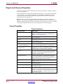
Specifying Part Numbers
You can specify a part number at various points in the design flow, not all of which
require the -p option.
•
In the input netlist (does not require the -p option)
•
In a Netlist Constraints File (NCF) (does not require the -p option)
•
With the -p option when you run a netlist reader (EDIF2NGD)
•
In the User Constraints File (UCF) (does not require the -p option)
•
With the -p option when you run NGDBuild
By the time you run NGDBuild, you must have already specified a device
architecture.
•
With the -p option when you run MAP
When you run MAP you must specify an architecture, device, and package, either
on the MAP command line or earlier in the design flow. If you do not specify a
speed, MAP selects a default speed. You can only run MAP using a part number
from the architecture you specified when you ran NGCBuild.
•
With the -p option when you run SmartXplorer (FPGA designs only)
•
With the -p option when you run CPLDFit (CPLD designs only)
Note Part numbers specified in a later step of the design flow override a part number
specified in an earlier step. For example, a part specified when you run MAP overrides a
part specified in the input netlist.
Examples
The following examples show how to specify parts on the command line.
Command Line Tools User Guide
UG628 (v14.7) October 2, 2013
Send Feedback
www.xilinx.com
13
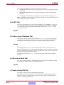
Chapter 1: Introduction
Specification
Examples
Architecture only
virtex4
virtex5
spartan3
spartan3a
xc9500
xpla3 (CoolRunner™ XPLA3 devices)
Device only
xc4vfx12
xc3s100e
DevicePackage
xc4fx12sf363
xc3s100evq100
Device-Package
xc4vfx12-sf363
xc3s100e-vq100
DeviceSpeed-Package
xc4vfx1210-sf363
xc3s100e4-vq100
DevicePackage-Speed
xc4fx12sf363-10
xc3s100evq100-4
Device-Speed-Package
xc4vfx12-10-sf363
xc3s100e-4-vq100
Device-SpeedPackage
xc4vfx12-10sf363
xc3s100e-4vq100
Invoking Command Line Programs
You start Xilinx® command line programs by entering a command at the Linux or DOS
command line. See the program-specific chapters in this book for the appropriate syntax
Xilinx also offers the XFLOW program, which lets you automate the running of several
programs at one time. See the XFLOW chapter for more information.
Send Feedback
14
www.xilinx.com
Command Line Tools User Guide
UG628 (v14.7) October 2, 2013
Chapter 2
Design Flow
This chapter describes the process for creating, implementing, verifying, and
downloading designs for Xilinx® FPGA and CPLD devices. For a complete
description of Xilinx FPGA and CPLDs devices, refer to the Xilinx Data Sheets at:
http://www.xilinx.com/support/
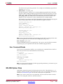
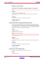
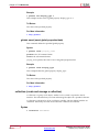
Design Flow Overview
The standard design flow comprises the following steps:
1.
Design Entry and Synthesis - Create your design using a Xilinx®-supported
schematic editor, a Hardware Description Language (HDL) for text-based entry, or
both. If you use an HDL for text-based entry, you must synthesize the HDL file into
an EDIF file or, if you are using the Xilinx Synthesis Technology (XST) GUI, you
must synthesize the HDL file into an NGC file.
2.
Design Implementation - Convert the logical design file format, such as EDIF, that
you created in the design entry and synthesis stage into a physical file format by
implementing to a specific Xilinx architecture. The physical information is contained
in the Native Circuit Description (NCD) file for FPGAs and the VM6 file for CPLDs.
Then create a bitstream file from these files and optionally program a PROM or
EPROM for subsequent programming of your Xilinx device.
3.
Design Verification - Using a gate-level simulator or cable, ensure that your design
meets timing requirements and functions properly. See the iMPACT online help for
information about Xilinx download cables and demonstration boards.
The full design flow is an iterative process of entering, implementing, and verifying
your design until it is correct and complete. The command line tools provided with the
ISE® Design Suite allow quick design iterations through the design flow cycle. Xilinx
devices permit unlimited reprogramming. You do not need to discard devices when
debugging your design in circuit.
Command Line Tools User Guide
UG628 (v14.7) October 2, 2013
Send Feedback
www.xilinx.com
15
Chapter 2: Design Flow
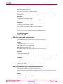
Xilinx Design Flow
This figure shows the standard Xilinx design flow.
Send Feedback
16
www.xilinx.com
Command Line Tools User Guide
UG628 (v14.7) October 2, 2013
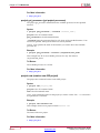
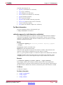
Chapter 2: Design Flow
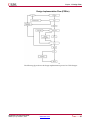
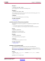
Xilinx Software Design Flow (FPGAs)
This figure shows the Xilinx software flow chart for FPGA designs.
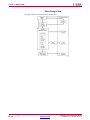
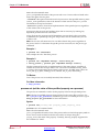
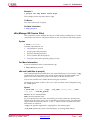
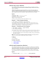
Xilinx Software Design Flow (CPLDs)
This figure shows the Xilinx software flow chart for CPLD designs.
Command Line Tools User Guide
UG628 (v14.7) October 2, 2013
Send Feedback
www.xilinx.com
17
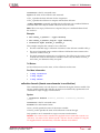
Chapter 2: Design Flow
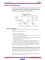
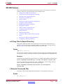
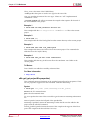
Design Entry and Synthesis
You can enter a design with a schematic editor or a text-based tool. Design entry begins
with a design concept, expressed as a drawing or functional description. From the
original design, a netlist is created, then synthesized and translated into a native generic
object (NGO) file. This file is fed into the Xilinx® software program called NGDBuild,
which produces a logical Native Generic Database (NGD) file.
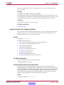
The following figure shows the design entry and synthesis process.
Design Entry Flow
Hierarchical Design
Design hierarchy is important in both schematic and HDL entry for the following
reasons:
•
Helps you conceptualize your design
•
Adds structure to your design
•
Promotes easier design debugging
•
Makes it easier to combine different design entry methods (schematic, HDL, or state
editor) for different parts of your design
•
Makes it easier to design incrementally, which consists of designing, implementing,
and verifying individual parts of a design in stages
•
Reduces optimization time
•
Facilitates concurrent design, which is the process of dividing a design among a
number of people who develop different parts of the design in parallel.
In hierarchical designing, a specific hierarchical name identifies each library element,
unique block, and instance you create. The following example shows a hierarchical
name with a 2-input OR gate in the first instance of a multiplexer in a 4-bit counter:
/Acc/alu_1/mult_4/8count_3/4bit_0/mux_1/or2
Xilinx® strongly recommends that you name the components and nets in your design.
These names are preserved and used by FPGA Editor. These names are also used for
back-annotation and appear in the debug and analysis tools. If you do not name your
components and nets, the Schematic Editor automatically generates the names. For
example, if left unnamed, the software might name the previous example, as follows:
/$1a123/$1b942/$1c23/$1d235/$1e121/$1g123/$1h57
Note It is difficult to analyze circuits with automatically generated names, because the
names only have meaning for Xilinx software.
Send Feedback
18
www.xilinx.com
Command Line Tools User Guide
UG628 (v14.7) October 2, 2013
Chapter 2: Design Flow
Partitions
In hierarchical design flows, such as Design Preservation and Partial Reconfiguration,
partitions are used to define hierarchical boundaries so that a complex design can be
broken up into smaller blocks. Partitions create a boundary or insulation around the
hierarchical module, which isolates the module from other parts of the design. A
partition that has been implemented and exported can be re-inserted into the design
using a simple cut-and-paste type function, which preserves the placement and routing
results for the isolated module. All of the partition definitions and controls are done in a
file called xpartition.pxml. For more information on using hierarchical design flows
and implementing partitions, see the Hierarchical Design Methodology Guide (UG748).
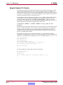
PXML File
Partition definitions are contained in the xpartition.pxml file. The PXML file name
is case-sensitive, and must be named xpartition.pxml. The top level module
of the design must be defined as a partition in addition to any optional lower level
partitions. The PXML file can be created by hand, from scripts, or from a tool such as
the PlanAhead™ software. The PXML will be picked up automatically by the ISE®
Design Suite implementation tools when located in the current working directory.
For more information about using the xpartition.pxml file, see the Hierarchical
Design Methodology Guide (UG748). An example xpartition.pxml file is available at
%XILINX%/PlanAhead/examples/templates (where %XILINX% is your installation
directory) if you wish to create a PXML file by hand.
Note All paths in the PXML file must be absolute paths.
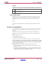
<?xml version="1.0" encoding="UTF-8" ?>
<Project FileVersion="1.2" Name="Example" ProjectVersion="2.0">
<Partition Name="/top" State="implement" ImportLocation="NONE">
<Partition Name="/top/module_A" State="import" ImportLocation="/home/user/Example/import" Preserve="routing">
</Partition>
<Partition Name="/top/module_B" State="import" ImportLocation="/home/user/Example/import" Preserve="routing">
</Partition>
<Partition Name="/top/module_C" State="implement" ImportLocation="/home/user/Example/import" Preserve="placement">
</Partition>
</Partition>
</Project>
PXML attributes for Project definition
Attribute name
Value
Description
FileVersion
1.2
Used for internal purposes. Do not change this
value.
Name
Project_Name
Project_Name is user defined.
ProjectVersion
2.0
Used for internal purposes. Do not change this
value.
Command Line Tools User Guide
UG628 (v14.7) October 2, 2013
Send Feedback
www.xilinx.com
19
Chapter 2: Design Flow
PXML attributes for Partition definition
Attribute name
Value
Description
Name
Partition_Name
Hierarchical instance name of module in which
the partition should be applied.
State
“implement”
Partition is implemented from scratch.
“import”
Partition is imported and preserved according
to the level set by Preserve.
ImportLocation
path
Ignored if State does not equal “import.”
The path can be relative or absolute, but the
location specified must contain a valid "export"
directory when State=import. “NONE” is a
predefined keyword for no import directory.
ImportTag
Partition_Name
Allows a partition to be imported into a
different level of hierarchy than it was initially
implemented in. Set the value to the hierarchical
instance name of the partition where it was
implemented.
Preserve
“routing”
100% placement and routing is preserved. This
is the default for the top level Partition.
“placement”
Placement is preserved but routing can be
modified.
“synthesis”
Placement and routing can be modified.
“inherit”
Inherit value from the parent partition. This is
the default for all partitions except the top level
partition.
“all”
Enables the implementation tools to do
optimization on partition ports connected to
constraints as well as unused partition ports.
“none”
Normal partition optimization rules apply.
Optimization is allowed only within partition
boundaries. This is the default value.
BoundaryOpt
Schematic Entry Overview
Schematic tools provide a graphic interface for design entry. You can use these tools to
connect symbols representing the logic components in your design. You can build your
design with individual gates, or you can combine gates to create functional blocks.
This section focuses on ways to enter functional blocks using library elements and the
CORE Generator™ tool.
Library Elements
Primitives and macros are the “building blocks” of component libraries. Xilinx®
libraries provide primitives, as well as common high-level macro functions. Primitives
are basic circuit elements, such as AND and OR gates. Each primitive has a unique
library name, symbol, and description. Macros contain multiple library elements, which
can include primitives and other macros.
You can use the following types of macros with Xilinx FPGAs:
•
Soft macros have pre-defined functionality but have flexible mapping, placement,
and routing. Soft macros are available for all FPGAs.
•
Relationally placed macros (RPMs) have fixed mapping and relative placement.
RPMs are available for all device families, except the XC9500 family.
Send Feedback
20
www.xilinx.com
Command Line Tools User Guide
UG628 (v14.7) October 2, 2013
Chapter 2: Design Flow
Macros are not available for synthesis because synthesis tools have their own module
generators and do not require RPMs. If you wish to override the module generation, you
can instantiate modules created using CORE Generator. For most leading-edge synthesis
tools, this does not offer an advantage unless it is for a module that cannot be inferred.
CORE Generator Tool (FPGAs Only)
The Xilinx CORE Generator tool delivers parameterizable cores that are optimized
for Xilinx FPGAs. The library includes cores ranging from simple delay elements to
complex DSP (Digital Signal Processing) filters and multiplexers. For details, refer to the
CORE Generator Help (part of ISE Help). You can also refer to the Xilinx IP (Intellectual
Property) Center Web site at http://www.xilinx.com/ipcenter, which offers the latest IP
solutions. These solutions include design reuse tools, free reference designs, Digital
Signal Processing (DSP), PCI™ solutions, IP implementation tools, cores, specialized
system level services, and vertical application IP solutions.
HDL Entry and Synthesis
A typical Hardware Description Language (HDL) supports a mixed-level description in
which gate and netlist constructs are used with functional descriptions. This mixed-level
capability lets you describe system architectures at a high level of abstraction and then
incrementally refine the detailed gate-level implementation of a design.
HDL descriptions offer the following advantages:
•
You can verify design functionality early in the design process. A design written as
an HDL description can be simulated immediately. Design simulation at this high
level, at the gate-level before implementation, allows you to evaluate architectural
and design decisions.
•
An HDL description is more easily read and understood than a netlist or schematic
description. HDL descriptions provide technology-independent documentation
of a design and its functionality. Because the initial HDL design description is
technology independent, you can use it again to generate the design in a different
technology, without having to translate it from the original technology.
•
Large designs are easier to handle with HDL tools than schematic tools.
After you create your HDL design, you must synthesize it. During synthesis, behavioral
information in the HDL file is translated into a structural netlist, and the design is
optimized for a Xilinx® device. Xilinx supports HDL synthesis tools for several
third-party synthesis vendors. In addition, Xilinx offers its own synthesis tool, Xilinx
Synthesis Technology (XST). For more information, see the XST User Guide for Virtex-4,
Virtex-5, Spartan-3, and Newer CPLD Devices (UG627) or the XST User Guide for Virtex-6,
Spartan-6, and 7 Series Devices (UG687). For detailed information on synthesis, see the
Synthesis and Simulation Design Guide (UG626).
Functional Simulation
After you create your design, you can simulate it. Functional simulation tests the
logic in your design to determine if it works properly. You can save time during
subsequent design steps if you perform functional simulation early in the design flow.
See Simulation for more information.
Constraints
You may want to constrain your design within certain timing or placement parameters.
You can specify mapping, block placement, and timing specifications.
Command Line Tools User Guide
UG628 (v14.7) October 2, 2013
Send Feedback
www.xilinx.com
21
Chapter 2: Design Flow
You can enter constraints manually or use the Constraints Editor or FPGA Editor, which
are graphical user interface (GUI) tools provided by Xilinx®. You can use the Timing
Analyzer GUI or TRACE command line program to evaluate the circuit against these
constraints by generating a static timing analysis of your design. See the TRACE chapter
and the online Help provided with the ISE® Design Suite for more information. For
more information on constraints, see the Constraints Guide (UG625).
Mapping Constraints (FPGAs Only)
You can specify how a block of logic is mapped into CLBs using an FMAP for all
Spartan® and Virtex® FPGA architectures. These mapping symbols can be used in
your schematic. However, if you overuse these specifications, it may be difficult to
route your design.
Block Placement
Block placement can be constrained to a specific location, to one of multiple locations, or
to a location range. Locations can be specified in the schematic, with synthesis tools,
or in the User Constraints File (UCF). Poor block placement can adversely affect both
the placement and the routing of a design. Only I/O blocks require placement to meet
external pin requirements.
Timing Specifications
You can specify timing requirements for paths in your design. PAR uses these timing
specifications to achieve optimum performance when placing and routing your design.
Netlist Translation Programs
Netlist translation programs let you read netlists into the Xilinx® software tools.
EDIF2NGD lets you read an Electronic Data Interchange Format (EDIF) 2 0 0 file. The
NGDBuild program automatically invokes these programs as needed to convert your
EDIF file to an NGD file, the required format for the Xilinx software tools. NGC files
output from the Xilinx XST synthesis tool are read in by NGDBuild directly.
You can find detailed descriptions of the EDIF2NGD, and NGDBuild programs in the
NGDBuild chapter and the EDIF2NGD and NGDBuild Appendix.
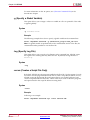
Design Implementation
Design Implementation begins with the mapping or fitting of a logical design file to a
specific device and is complete when the physical design is successfully routed and a
bitstream is generated. You can alter constraints during implementation just as you did
during the Design Entry step. See Constraints for information.
The following figure shows the design implementation process for FPGA designs:
Send Feedback
22
www.xilinx.com
Command Line Tools User Guide
UG628 (v14.7) October 2, 2013
Chapter 2: Design Flow
Design Implementation Flow (FPGAs)
The following figure shows the design implementation process for CPLD designs:
Command Line Tools User Guide
UG628 (v14.7) October 2, 2013
Send Feedback
www.xilinx.com
23
Chapter 2: Design Flow
Design Implementation Flow (CPLDs)
Mapping (FPGAs Only)
For FPGAs, the MAP command line program maps a logical design to a Xilinx® FPGA.
The input to MAP is an NGD file, which contains a logical description of the design in
terms of both the hierarchical components used to develop the design and the lower-level
Xilinx primitives, and any number of NMC (hard placed-and-routed macro) files, each
of which contains the definition of a physical macro. MAP then maps the logic to the
components (logic cells, I/O cells, and other components) in the target Xilinx FPGA.
The output design from MAP is an NCD file, which is a physical representation of
the design mapped to the components in the Xilinx FPGA. The NCD file can then be
placed and routed, using the PAR command line program. See the MAP chapter for
detailed information.
Send Feedback
24
www.xilinx.com
Command Line Tools User Guide
UG628 (v14.7) October 2, 2013
Chapter 2: Design Flow
Note MAP provides options that enable advanced optimizations that are capable
of improving timing results beyond standard implementations. These advanced
optimizations can transform a design prior to or after placement. Optimizations can
be applied at two different stages in the Xilinx design flow. The first stage happens
right after the initial mapping of the logic to the architecture slices; the second stage if
after placement. See Re-Synthesis and Physical Synthesis Optimizations in the MAP
chapter for more information.
Placing and Routing (FPGAs Only)
For FPGAs, the PAR command line program takes a mapped NCD file as input, places
and routes the design, and outputs a placed and routed Native Circuit Description
(NCD) file, which is used by the bitstream generator, BitGen. The output NCD file can
also act as a guide file when you reiterate placement and routing for a design to which
minor changes have been made after the previous iteration. See the PAR chapter for
detailed information.
You can also use FPGA Editor to do the following:
•
Place and route critical components before running automatic place and route tools
on an entire design.
•
Modify placement and routing manually. The editor allows both automatic and
manual component placement and routing.
Note For more information, see the online Help provided with FPGA Editor.
Bitstream Generation (FPGAs Only)
For FPGAs, the BitGen command line program produces a bitstream for Xilinx®
device configuration. BitGen takes a fully routed NCD file as its input and produces
a configuration bitstream, which is a binary file with a .bit extension. The BIT file
contains all of the configuration information from the NCD file defining the internal
logic and interconnections of the FPGA, plus device-specific information from other files
associated with the target device. See the BitGen chapter for detailed information.
After you generate your BIT file, you can download it to a device using the iMPACT GUI.
You can also format the BIT file into a PROM file using the PROMGen command line
program and then download it to a device using the iMPACT GUI. See the PROMGen
chapter of this guide or the iMPACT online help for more information.
Design Verification
Design verification is testing the functionality and performance of your design. You can
verify Xilinx® designs in the following ways:
•
Simulation (functional and timing)
•
Static timing analysis
•
In-circuit verification
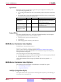
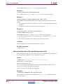
The following table lists the different design tools used for each verification type.
Command Line Tools User Guide
UG628 (v14.7) October 2, 2013
Send Feedback
www.xilinx.com
25
Chapter 2: Design Flow
Verification Tools
Verification Type
Tools
Simulation
Third-party simulators (integrated and
non-integrated)
Static Timing Analysis
TRACE (command line program)
Timing Analyzer (GUI)
Mentor Graphics TAU and Innoveda BLAST
software for use with the STAMP file format
(for I/O timing verification only)
In-Circuit Verification
Design Rule Checker (command line program)
Download cable
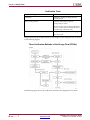
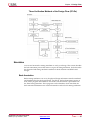
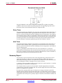
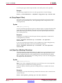
Design verification procedures should occur throughout your design process, as shown
in the following figures.
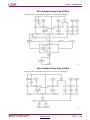
Three Verification Methods of the Design Flow (FPGAs)
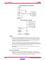
The following figure shows the verification methods of the design flow for CPLDs.
Send Feedback
26
www.xilinx.com
Command Line Tools User Guide
UG628 (v14.7) October 2, 2013
Chapter 2: Design Flow
Three Verification Methods of the Design Flow (CPLDs)
Simulation
You can run functional or timing simulation to verify your design. This section describes
the back-annotation process that must occur prior to timing simulation. It also describes
the functional and timing simulation methods for both schematic and HDL-based
designs.
Back-Annotation
Before timing simulation can occur, the physical design information must be translated
and distributed back to the logical design. For FPGAs, this back-annotation process is
done with a program called NetGen. For CPLDs, back-annotation is performed with
the TSim Timing Simulator. These programs create a database, which translates the
back-annotated information into a netlist format that can be used for timing simulation.
Command Line Tools User Guide
UG628 (v14.7) October 2, 2013
Send Feedback
www.xilinx.com
27
Chapter 2: Design Flow
Back-Annotation Flow for FPGAs
Back-Annotation (CPLDs)
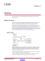
NetGen
NetGen is a command line program that distributes information about delays, setup
and hold times, clock to out, and pulse widths found in the physical Native Circuit
Description (NCD) design file back to the logical Native Generic Database (NGD) file
and generates a Verilog or VHDL netlist for use with supported timing simulation,
equivalence checking, and static timing analysis tools.
NetGen reads an NCD as input. The NCD file can be a mapped-only design, or a
partially or fully placed and routed design. An NGM file, created by MAP, is an optional
source of input. NetGen merges mapping information from the optional NGM file with
placement, routing, and timing information from the NCD file.
Note NetGen reads an NGA file as input to generate a timing simulation netlist for
CPLD designs.
See the NetGen chapter for detailed information.
Functional Simulation
Functional simulation determines if the logic in your design is correct before you
implement it in a device. Functional simulation can take place at the earliest stages of
the design flow. Because timing information for the implemented design is not available
at this stage, the simulator tests the logic in the design using unit delays.
Send Feedback
28
www.xilinx.com
Command Line Tools User Guide
UG628 (v14.7) October 2, 2013
Chapter 2: Design Flow
Note It is usually faster and easier to correct design errors if you perform functional
simulation early in the design flow.
Timing Simulation
Timing simulation verifies that your design runs at the desired speed for your device
under worst-case conditions. This process is performed after your design is mapped,
placed, and routed for FPGAs or fitted for CPLDs. At this time, all design delays are
known.
Timing simulation is valuable because it can verify timing relationships and determine
the critical paths for the design under worst-case conditions. It can also determine
whether or not the design contains set-up or hold violations.
Before you can simulate your design, you must go through the back-annotation process,
above. During this process, NetGen creates suitable formats for various simulators.
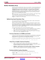
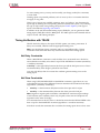
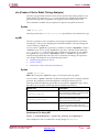
HDL-Based Simulation
Xilinx® supports functional and timing simulation of HDL designs at the following
points:
•
•
•
Register Transfer Level (RTL) simulation, which may include the following:
–
Instantiated UNISIM library components
–
CORE Generator™ models
–
Dedicated blocks (SecureIP)
Post-synthesis functional simulation with one of the following:
–
Gate-level UNISIM library components
–
CORE Generator models
–
Hard IP (SecureIP)
Post-implementation back-annotated timing simulation with the following:
–
SIMPRIM library components
–
Hard IP (SecureIP)
–
Standard Delay Format (SDF) file
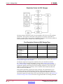
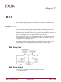
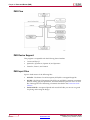
The following figure shows when you can perform functional and timing simulation:
Command Line Tools User Guide
UG628 (v14.7) October 2, 2013
Send Feedback
www.xilinx.com
29
Chapter 2: Design Flow
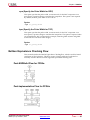
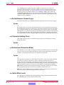
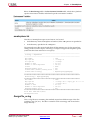
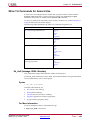
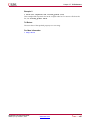
Simulation Points for HDL Designs
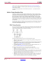
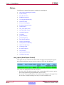
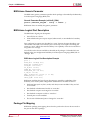
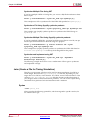
The three primary simulation points can be expanded to allow for two post-synthesis
simulations. These points can be used if the synthesis tool cannot write VHDL or
Verilog, or if the netlist is not in terms of UNISIM components. The following table lists
all the simulation points available in the HDL design flow.
Five Simulation Points in HDL Design Flow
Simulation
UNISIM
RTL
X
Post-Synthesis
X
SIMPRIM
SDF
Functional
Post-NGDBuild
(Optional)
X
Functional Post-MAP
(Optional)
X
X
Post-Route Timing
X
X
These simulation points are described in the “Simulation Points” section of the Synthesis
and Simulation Design Guide (UG626).
The libraries required to support the simulation flows are described in detail in
the “VHDL/Verilog Libraries and Models” section of the Synthesis and Simulation
Design Guide (UG626). The flows and libraries support close functional equivalence of
initialization behavior between functional and timing simulations. This is due to the
addition of methodologies and library cells to simulate Global Set/Reset (GSR) and
Global 3-State (GTS) behavior.
Xilinx VHDL simulation supports the VITAL standard. This standard allows you
to simulate with any VITAL-compliant simulator. Built-in Verilog support allows
you to simulate with the Cadence Verilog-XL and compatible simulators. Xilinx HDL
simulation supports all current Xilinx FPGA and CPLD devices. Refer to the Synthesis and
Simulation Design Guide (UG626) for the list of supported VHDL and Verilog standards.
Send Feedback
30
www.xilinx.com
Command Line Tools User Guide
UG628 (v14.7) October 2, 2013
Chapter 2: Design Flow
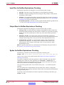
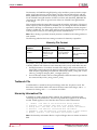
Static Timing Analysis (FPGAs Only)
Static timing allows you to determine path delays in your design. Following are the
two major goals of static timing analysis:
•
Timing verification
This is verifying that the design meets your timing constraints.
•
Reporting
This is enumerating input constraint violations and placing them into an accessible
file. You can analyze partially or completely placed and routed designs. The timing
information depends on the placement and routing of the input design.
You can run static timing analysis using the Timing Reporter And Circuit Evaluator
(TRACE) command line program. See the TRACE chapter for detailed information. You
can also use the Timing Analyzer to perform this function. See the Help that comes with
Timing Analyzer for additional information. Use either tool to evaluate how well the
place and route tools met the input timing constraints.
In-Circuit Verification
As a final test, you can verify how your design performs in the target application.
In-circuit verification tests the circuit under typical operating conditions. Because you
can program your FPGA devices repeatedly, you can easily load different iterations of
your design into your device and test it in-circuit. To verify your design in-circuit,
download your design bitstream into a device with the appropriate Xilinx® cable.
Note For information about Xilinx cables and hardware, see the iMPACT online help.
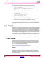
Design Rule Checker (FPGAs Only)
Before generating the final bitstream, it is important to use the DRC option in BitGen
to evaluate the NCD file for problems that could prevent the design from functioning
properly. DRC is invoked automatically unless you use the -d option. See the Physical
Design Rule Check chapter and the BitGen chapter for detailed information.
Probe
The Xilinx PROBE function in FPGA Editor provides real-time debug capability good
for analyzing a few signals at a time. Using PROBE a designer can quickly identify and
route any internal signals to available I/O pins without having to replace and route the
design. The real-time activity of the signal can then be monitored using normal lab test
equipment such as logic/state analyzers and oscilloscopes.
ChipScope™ ILA and ChipScope Pro
The ChipScope toolset was developed to assist engineers working at the PCB level.
ChipScope ILA actually embeds logic analyzer cores into your design. These logic cores
allow the user to view all the internal signals and nodes within an FPGA. Triggers are
changeable in real-time without affecting the user logic or requiring recompilation
of the user design.
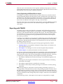
FPGA Design Tips
The Xilinx® FPGA architecture is best suited for synchronous design. Strict synchronous
design ensures that all registers are driven from the same time base with no clock skew.
This section describes several tips for producing high-performance synchronous designs.
Command Line Tools User Guide
UG628 (v14.7) October 2, 2013
Send Feedback
www.xilinx.com
31
Chapter 2: Design Flow
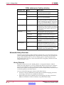
Design Size and Performance
Information about design size and performance can help you to optimize your design.
When you place and route your design, the resulting report files list the number of
CLBs, IOBs, and other device resources available. A first pass estimate can be obtained
by processing the design through the MAP program.
If you want to determine the design size and performance without running automatic
implementation software, you can quickly obtain an estimate from a rough calculation
based on the Xilinx FPGA architecture.
Send Feedback
32
www.xilinx.com
Command Line Tools User Guide
UG628 (v14.7) October 2, 2013
Chapter 3
PARTGen
This chapter describes PARTGen.
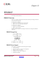
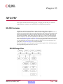
PARTGen Overview
PARTGen is a Xilinx® command line tool that displays architectural details about
supported Xilinx devices.
Device Support
This program is compatible with the following device families:
•
7 series and Zynq™
•
Spartan®-3, Spartan-3A, Spartan-3E, and Spartan-6
•
Virtex®-4, Virtex-5, and Virtex-6
•
CoolRunner™ XPLA3 and CoolRunner-II
•
XC9500 and XC9500XL
PARTGen Input Files
PARTGen does not have any user input files.
PARTGen Output Files
PARTGen outputs two file types:
•
PARTGen Partlist Files (ASCII and XML)
•
PARTGen Package Files (ASCII)
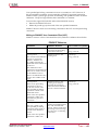
PARTGen Partlist Files
PARTGen partlist files contain detailed information about architectures and devices,
including supported synthesis tools. Partlist files are generated in both ASCII (.xct)
and XML (.xml) formats.
The partlist file is automatically generated in XML format whenever a partlist file is
created with the PARTGen -p (Generate Partlist and Package Files) or PARTGen -v
(Generate Partlist and Package Files) options. No separate command line option is
required.
Command Line Tools User Guide
UG628 (v14.7) October 2, 2013
Send Feedback
www.xilinx.com
33
Chapter 3: PARTGen
The partlist file is a series of part entries. There is one entry for every part supported
in the installed software. The following sections describe the information contained
in the partlist file.
•
PARTGen Partlist File Header
•
PARTGen Partlist File Device Attributes for Both -p and -v Options
•
PARTGen Partlist File Device Attributes for -v Option Only
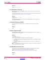
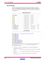
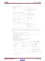
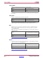
PARTGen Partlist File Header
The first part of a PARTGen partlist file is a header for the entry.
part
architecture
family
partname
diename
packagefilename
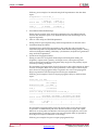
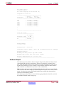
PARTGen Partlist File Header Example for XC6VLX550TFF1759 Device
partVIRTEX XC6VLX550Tff1759 NA.die xc6vlx550tff1759.pkg
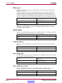
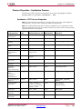
PARTGen Partlist File Device Attributes for both -p and -v Options
The following PARTGen partlist file device attributes display for both the -p and -v
command line options.
•
CLB row and column sizes
NCLBROWS=# NCLBCOLS=#
•
Sub-family designation
STYLE=sub_family (For example, STYLE = Virtex6)
•
Input registers
IN_FF_PER_IOB=#
•
Output registers
OUT_FF_PER_IOB=#
•
Number of pads per row and per column
NPADS_PER_ROW=# NPADS_PER_COL=#
•
Bitstream information
–
Number of frames: NFRAMES=#
–
Number bits/frame: NBITSPERFRAME=#
•
Stepping levels supported: STEP=#
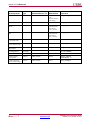
•
I/O Standards
For each I/O standard, PARTGen now reports all properties in a parsable format.
This allows third party tools to perform complete I/O banking design rules checking
(DRC).
The following information has been added to the partlist.xct and
partlist.xml output for each available I/O standard:
IOSTD_NAME: LVTTL \
IOSTD_DRIVE: 12 2 4 6 8 16 24
\
IOSTD_SLEW: SLOW FAST
\
IOSTD_DIRECTION: INPUT=1 OUTPUT=1 BIDIR=1 \
IOSTD_INPUTTERM: NONE \
IOSTD_OUTPUTTERM: NONE \
IOSTD_VCCO: 3.300000 \
IOSTD_VREF: 100.000000 \
IOSTD_VRREQUIRED: 0 \
IOSTD_DIFFTERMREQUIRED: 0 \
Send Feedback
34
www.xilinx.com
Command Line Tools User Guide
UG628 (v14.7) October 2, 2013
Chapter 3: PARTGen
For IOSTD_DRIVE and IOSTD_SLEW, the default values are reported first in the
list. For true/false values:
–
1 indicates true
–
0 indicates false
A value of 100.000000 for IOSTD_VREF indicates that this keyword is undefined
for this standard.
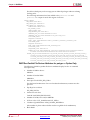
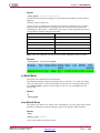
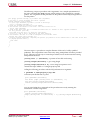
•
SO and WASSO Calculations
PARTGen now exports I/O standard and device properties in a machine readable
format. This allows third party tools to perform SSO and WASSO calculations.
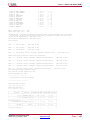
SSO data consists of two parts:
–
The maximum number of SSOs allowed per power/ground pair
–
The number of power/ground pairs for a given bank.
This data has been added to the partlist.xct and partlist.xml output for
each device/package combination. The number of power/ground pairs is listed
by bank number:
PER_BANK_PWRGND_PAIRS\
BANK_SSO NAME=0 TYPE=INT
BANK_SSO NAME=1 TYPE=INT
BANK_SSO NAME=2 TYPE=INT
BANK_SSO NAME=3 TYPE=INT
BANK_SSO NAME=4 TYPE=INT
BANK_SSO NAME=5 TYPE=INT
BANK_SSO NAME=6 TYPE=INT
BANK_SSO NAME=7 TYPE=INT
BANK_SSO NAME=8 TYPE=INT
1\
1\
1\
1\
1\
5\
5\
3\
3\
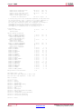
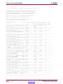
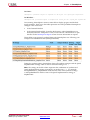
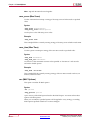
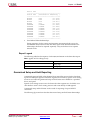
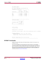
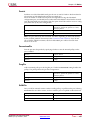
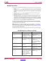
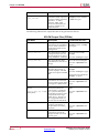
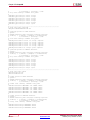
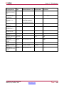
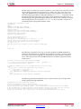
The maximum number of SSOs allowed per power/ground pair is reported using
the SSO_PER_IOSTD keyword. Each entry reflects the maximum number of SSOs
(column 6) for the I/O standard (column 3), drive strength (column 2), and slew
rate (column 4) shown.
For example, LVTTL, with drive strength 12 and slew rate SLOW, has a maximum of
15 SSOs per power/ground pair.
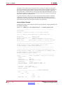
MAX_SSO_PER_IOSTD_PER_BANK\
IOSTD_SSO DRIVE=12 NAME=LVTTL SLEW=SLOW TYPE=INT 15\
IOSTD_SSO DRIVE=12 NAME=LVTTL SLEW=FAST TYPE=INT 10\
IOSTD_SSO DRIVE=2 NAME=LVTTL SLEW=SLOW TYPE=INT 68\
IOSTD_SSO DRIVE=2 NAME=LVTTL SLEW=FAST TYPE=INT 40\
IOSTD_SSO DRIVE=4 NAME=LVTTL SLEW=SLOW TYPE=INT 41\
IOSTD_SSO DRIVE=4 NAME=LVTTL SLEW=FAST TYPE=INT 24\
IOSTD_SSO DRIVE=6 NAME=LVTTL SLEW=SLOW TYPE=INT 29\
IOSTD_SSO DRIVE=6 NAME=LVTTL SLEW=FAST TYPE=INT 17\
IOSTD_SSO DRIVE=8 NAME=LVTTL SLEW=SLOW TYPE=INT 22\
IOSTD_SSO DRIVE=8 NAME=LVTTL SLEW=FAST TYPE=INT 13\
IOSTD_SSO DRIVE=16 NAME=LVTTL SLEW=SLOW TYPE=INT 11\
IOSTD_SSO DRIVE=16 NAME=LVTTL SLEW=FAST TYPE=INT 8\
IOSTD_SSO DRIVE=24 NAME=LVTTL SLEW=SLOW TYPE=INT 7\
IOSTD_SSO DRIVE=24 NAME=LVTTL SLEW=FAST TYPE=INT 5\
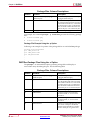
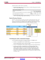
•
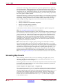
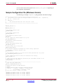
Device global, local and regional clocking properties
For each type of clock available on the device, PARTGen now reports:
–
Which pin number can behave as which clock type
–
Which I/O can be driven by this clock pin
Command Line Tools User Guide
UG628 (v14.7) October 2, 2013
Send Feedback
www.xilinx.com
35
Chapter 3: PARTGen
This allows third party tools to assign pins on Xilinx® packages without violating
clocking rules.
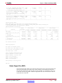
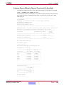
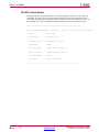
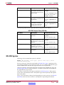
The following information has been added to the partlist.xct and
partlist.xml output for each clock region of a device:
DEVICE_CLKRGN\
NUM_CLKRGN TYPE=INT 8\
NUM_CLKRGN_ROW TYPE=INT 4\
NUM_CLKRGN_COL TYPE=INT 2\
CLKRGN TYPE=STRING X0Y0\
CLK_CAPABLE_SCOPE\
UNASSOCIATED_PINS\
NUM_UNBONDED_PINS TYPE=INT 2\
UNBONDED_PIN_LIST TYPE=STRINGLIST T17R17\
UNBONDED_IOB_LIST TYPE=STRINGLIST IOB_X0Y15IOB_X0Y17\
ASSOCIATED_BUFIO\
NUM_BUFIO TYPE=INT 4\
BUFIO_SITES TYPE=STRINGLIST BUFIO_X0Y0BUFIO_X0Y1BUFIO_X1Y0BUFIO_X1Y1\
ASSOCIATED_BUFR\
NUM_BUFR TYPE=INT 2\
BUFR_SITES TYPE=STRINGLIST BUFR_X0Y0BUFR_X0Y1\
ASSOCIATED_PINS\
NUM_BONDED_PINS TYPE=INT 39\
BONDED_PIN_LIST TYPE=STRINGLIST V18V17W17Y17W19W18U17U16V20V19U15T15U19U18T18\
T17R18R17T20T19R16R15R20R19W8W9Y9Y10W7Y7W10W11W6Y6Y11Y12W5Y5W12\
BONDED_IOB_LIST TYPE=STRINGLIST IOB_X0Y0IOB_X0Y1IOB_X0Y2IOB_X0Y3IOB_X0Y4IOB_X0Y5IOB_\
X0Y6IOB_X0Y7IOB_X0Y8IOB_X0Y9IOB_X0Y10IOB_X0Y11IOB_X0Y12IOB_X0Y13IOB_X0Y14IOB_\
X0Y15IOB_X0Y16IOB_X0Y17IOB_X0Y18IOB_X0Y19IOB_X0Y22IOB_X0Y23IOB_X0Y24IOB_X0Y25IOB_\
X1Y16IOB_X1Y17IOB_X1Y18IOB_X1Y19IOB_X1Y20IOB_X1Y21IOB_X1Y22IOB_X1Y23IOB_X1Y24IOB_\
X1Y25IOB_X1Y26IOB_X1Y27IOB_X1Y28IOB_X1Y29IOB_X1Y30\
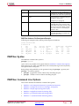
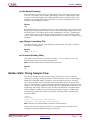
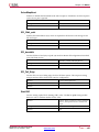
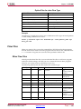
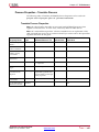
PARTGen Partlist File Device Attributes for partgen -v Option Only
The following PARTGen partlist file device attributes display for the -v command
line option only.
•
Number of IOBS in device
NIOBS=#
•
Number of bonded IOBS
NBIOBS=#
•
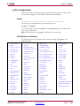
Slices per CLB: SLICES_PER_CLB=#
For slice-based architectures. For non-slice based architectures, assume one slice
per CLB.
•
Flip-flops for each slice
FFS_PER_SLICE=#
•
Latches for each slice
CAN BE LATCHES={TRUE|FALSE}
•
Number of DCMs, PLLs and/or MMCMs
•
LUTs in a slice: LUT_NAME=name LUT_SIZE=#
•
Number of global buffers: NUM_GLOBAL_BUFFERS=#
(The number of places where a buffer can drive a global clock combination)
•
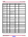
Block RAM
Send Feedback
36
www.xilinx.com
Command Line Tools User Guide
UG628 (v14.7) October 2, 2013
Chapter 3: PARTGen
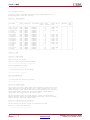
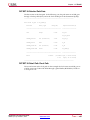
NUM_BLK_RAMS=# BLK_RAM_COLS=# BLK_RAM_COL0=# BLK_RAMCOL1=#
BLK_RAM_COL2=# BLK_RAM_COL_3=# BLK_RAM_SIZE=4096x1
BLK_RAM_SIZE=2048x2 BLK_RAM_SIZE=512x8 BLK_RAM_SIZE=256x16
Block RAM locations are given with reference to CLB columns. In the following
example, Block RAM 5 is positioned in CLB column 32.
NUM_BLK_RAMS=10 BLK_RAM_COL_5=32 BLK_RAM_SIZE=4096X1
•
Select RAM
NUM_SEL_RAMS=# SEL_RAM_SIZE=#X#
•
Select Dual Port RAM
SEL_DP_RAM={TRUE|FALSE}
This field indicates whether the select RAM can be used as a dual port ram. The
assumption is that the number of addressable elements is reduced by half, that is, the
size of the select RAM in Dual Port Mode is half that indicated by SEL_RAM_SIZE.
•
Speed grade information: SPEEDGRADE=#
Delays information no longer appears in the XCT and XML partlist files. Delay
information can be obtained using Speedprint. For more information, see the
Speedprint chapter in this guide.
•
Maximum LUT constructed in a slice
MAX_LUT_PER_SLICE=# (From all the LUTs in the slice)
•
Max LUT constructed in a CLB: MAX_LUT_PER_CLB=#
This field describes how wide a LUT can be constructed in the CLB from the
available LUTs in the slice.
•
Number of internal tristate buffers in a device
NUM_TBUFS PER ROW=#
•
If available on a particular device or package, PartGen reports:
NUM_PPC=#
NUM_GT=#
NUM_MONITOR=#
NUM_DPM=#
NUM_PMCD=#
NUM_DSP=#
NUM_FIFO=#
NUM_EMAC=#
NUM_MULT=#
PARTGen Package Files
PARTGen package files are ASCII formatted files that correlate IOBs with output
pin names. Package files are in XACT package format, which is a set of columns of
information about the pins of a particular package. The -p (terse) command line option
generates a three column entry describing the pins. The -v (verbose) command line
option adds six more columns describing the pins. The following sections describe the
information contained in the package files.
•
PARTGen Package Files With the -p Option
•
PARTGen Package Files With the -v Option
PARTGen Package Files Using the -p Option
The partgen -p command line option generates package files and displays a
three-column entry describing the pins. See the following table.
Command Line Tools User Guide
UG628 (v14.7) October 2, 2013
Send Feedback
www.xilinx.com
37
Chapter 3: PARTGen
Package Files Column Descriptions
Column
Contents
Description
1
pin (user accessible pin) or pkgpin
(dedicated pin)
Contains either pin (user accessible pin)
or pkgpin (dedicated pin)
2
pin name
For user accessible pins, the name of the
pin is the bonded pad name associated
with an IOB on the device, or the name
of a multi-purpose pin. For dedicated
pins, the name is either the functional
name of the pin, or no connection (N.C.
3
package pin
Specifies the package pin
For example, the command partgen -p xc6vlx75t generates the following package
files:
•
xc6vlx75tff484.pkg
•
xc6vlx75tff784.pkg
Package File Example Using the -p Option
Following is an example of a portion of the package file for an xc6vlx75tff484 package:
package xc6vlx75tff484
pin IPAD_X1Y25 G3
pin IPAD_X0Y31 M11
pin IOB_X0Y39 M18
.
.
.
PARTGen Package Files Using the -v Option
The partgen -v command line option generates package files and displays a
nine-column entry describing the pins. See the following table.
Package Files Column Descriptions
Column
Contents
Description
1
pin (user accessible pin) or pkgpin
(dedicated pin)
Contains either pin (user accessible pin)
or pkgpin (dedicated pin)
2
pin name
For user accessible pins, the name of the
pin is the bonded pad name associated
with an IOB on the device, or the name
of a multi-purpose pin. For dedicated
pins, the name is either the functional
name of the pin, or no connection (N.C.
3
package pin
Specifies the package pin
4
VREF BANK
A positive integer associated with
the relative bank, or 1 for no bank
association
5
VCCO BANK
A positive integer associated with
the relative bank, or 1 for no bank
association
6
function name
Consists of a string indicating how the
pin is used. If the pin is dedicated,
then the string will indicate a specific
function. If the pin is a generic user
Send Feedback
38
www.xilinx.com
Command Line Tools User Guide
UG628 (v14.7) October 2, 2013
Chapter 3: PARTGen
Column
Contents
Description
pin, the string is “IO”. If the pin is
multipurpose, an underscore-separated
set of characters will make up the string
7
CLB
Closest CLB row or column to the pin,
and appears in the form
R[0-9]C[0-9] or x[0-9]y[0-9]
8
LVDS IOB
A string for each pin associated with a
LVDS IOB. The string consists of and
index and the letter M or S. Index values
will go from 0 to the number of LVDS
pairs. The value for a non-LVDS pin
defaults to N.A.
9
flight-time data
Flight-time data in units of microns.
If no flight-time data is available, this
column contains N/A.
PARTGen Verbose Pin Descriptors Example
Following are examples of the verbose pin descriptors in PARTGen.
package xc6vlx75tff484
# PartGen L.44
#
pad
pin
#
name
name
pin
IPAD_X1Y25
G3
pin
IPAD_X0Y31
M11
pin
IOB_X0Y39
M18
pin
IOB_X0Y38
N18
vref vcco
bank bank
-1 -1
0
0
14 14
14 14
function
name
MGTRXP0_115
VN_0
IO_L0P_14
IO_L0N_14
nearest diff.
CLB
pair
N.A.
N.A.
N.A.
N.A.
X0Y38
0M
X0Y38
0S
tracelength
(um)
8594
1915
4111
3390
PARTGen Syntax
The PARTGen command line syntax is:
partgen options
options can be any number of the options listed in PARTGen Command Line Options.
Enter options in any order, preceded them with a dash (minus sign on the keyboard)
and separate them with spaces.
Both package and partlist files can be generated using the partgen -p (terse) and
partgen -v (verbose) options.
•
partgen -p generates a three column entry describing the pins.
•
partgen -v adds six more columns describing the pins.
PARTGen Command Line Options
This section describes the PARTGen command line options.
•
PARTGen –arch (Output Information for Specified Architecture)
•
PARTGen –i (Output List of Devices, Packages, and Speeds)
•
PARTGen –intstyle (Specify Integration Style)
•
PARTGen –nopkgfile (Generate No Package File)
•
PARTGen –p (Generate Partlist and Package Files)
•
PARTGen –v (Generate Partlist and Package Files)
Command Line Tools User Guide
UG628 (v14.7) October 2, 2013
Send Feedback
www.xilinx.com
39
Chapter 3: PARTGen
-arch (Output Information for Specified Architecture)
This option outputs a list of devices, packages, and speeds for a specified architecture.
Syntax
-arch architecture_name
Allowed values for architecture_name are:
•
acr2 (for Automotive CoolRunner™-II)
•
aspartan3 (for Automotive Spartan®-3)
•
aspartan3a (for Automotive Spartan-3A)
•
aspartan3adsp (for Automotive Spartan-3A DSP)
•
aspartan3e (for Automotive Spartan-3E)
•
aspartan6 (for Automotive Spartan-6)
•
kintex7 (for Kintex™-7)
•
kintex7l (for Kintex-7 Lower Power)
•
qrvirtex4 (for QPro™ Virtex®-4 Rad Tolerant)
•
qvirtex4 (for QPro Virtex-4 Hi-Rel)
•
qvirtex5 (for QPro Virtex-5 Hi-Rel)
•
qspartan6 (for QPro Spartan-6 Hi-Rel)
•
qvirtex6 (for QPro Virtex-6 Hi-Rel)
•
spartan3 (for Spartan-3)
•
spartan3a (for Spartan-3A)
•
spartan3adsp (for Spartan-3A DSP)
•
spartan3e (for Spartan-3E)
•
spartan6 (for Spartan-6)
•
virtex4 (for Virtex-4)
•
virtex5 (for Virtex-5)
•
virtex6 (for Virtex-6)
•
virtex6l (for Virtex-6 Lower Power)
•
virtex7 (for Virtex-7)
•
virtex7l (for Virtex-7 Lower Power)
•
xa9500xl (for Automotive XC9500XL)
•
xbr (for CoolRunner-II)
•
xc9500 (for XC9500)
•
xc9500xl (for XC9500XL)
•
xpla3 (for CoolRunner XPLA3)
-i (Output List of Devices, Packages, and Speeds)
This option outputs a list of devices, packages, and speeds for every installed device.
Syntax
-i
Send Feedback
40
www.xilinx.com
Command Line Tools User Guide
UG628 (v14.7) October 2, 2013
Chapter 3: PARTGen
-intstyle (Integration Style)
This option limits screen output, based on the integration style that you are running, to
warning and error messages only.
Syntax
-intstyle ise|xflow|silent
When using -intstyle, one of three modes must be specified:
•
-intstyle ise indicates the program is being run as part of an integrated design
environment.
•
-intstyle xflow indicates the program is being run as part of an integrated
batch flow.
•
-intstyle silent limits screen output to warning and error messages only.
Note -intstyle is automatically invoked when running in an integrated environment
such as Project Navigator or XFLOW.
-nopkgfile (Generate No Package File)
This option cancels the production of the package files when the -p and -v options are
used. The -nopkgfile option allows you to bypass creating package files.
Syntax
-nopkgfile
-p (Generate Partlist and Package Files)
This command line option generates:
•
Partlist files in ASCII (.xct) and XML (.xml) formats
•
Package files in ASCII (.pkg) format
Syntax
-p name
Valid entries for name include:
•
architectures
•
devices
•
parts
All files are placed in the working directory.
If an architecture, device, or part is not specified with this option, detailed information
for every installed device is submitted to the partlist.xct file. For more information,
see PARTGen Partlist Files.
The -p option generates more detailed information than the -arch option, but less
information than the -v option. The -p and -v options are mutually exclusive. You can
specify one or the other but not both. For more information see:
•
PARTGen Package Files
•
PARTGen Partlist Files
Command Line Tools User Guide
UG628 (v14.7) October 2, 2013
Send Feedback
www.xilinx.com
41
Chapter 3: PARTGen
Examples of Valid Command Line Entries
Name
Example Command Line Entry
architecture
-p virtex5
device
-p xc5vlx110t
part
-p xc5vlx110tff1136
-v (Generate Partlist and Package Files)
This command line option generates:
•
Partlist files in ASCII (.xct) and XML (.xml) formats
•
Package files in ASCII (.pkg) format
Syntax
-v name
Valid entries for name include:
•
architectures
•
devices
•
parts
If no architecture, device, or part is specified with the -v option, information for every
installed device is submitted to the partlist file. For more information, see PARTGen
Partlist Files.
The -v option generates more detailed information than the -p option. The -p and -v
options are mutually exclusive. You can specify one or the other but not both. For
more information, see:
•
PARTGen Package Files
•
PARTGen Partlist Files
Examples of Command Line Entries for the -v Option
Name
Example Command Line Entry
architecture
partgen -v virtex6
device
partgen -v xc5vlx110t
part
partgen -v xc5vlx110tff1136
Send Feedback
42
www.xilinx.com
Command Line Tools User Guide
UG628 (v14.7) October 2, 2013
Chapter 4
NetGen
This chapter describes the NetGen program, which generates netlists for use with
third-party tools.
NetGen Overview
NetGen is a command line executable that reads Xilinx® design files as input, extracts
data from the design files, and generates netlists that are used with supported
third-party simulation, equivalence checking, and static timing analysis tools.
NetGen can take an implemented design file and write out a single netlist for the
entire design, or multiple netlists for each module of a hierarchical design. Individual
modules of a design can be simulated on their own, or together at the top-level.
Modules identified with the KEEP_HIERARCHY attribute are written as user-specified
Verilog, VHDL, and SDF netlists with the -mhf (Multiple Hierarchical Files) option. See
Preserving and Writing Hierarchy Files for additional information.
NetGen Flows
NetGen can be described as having three fundamental flows: simulation, equivalency
checking, and third-party static timing analysis. This chapter contains flow-specific
sections that detail the use and features of NetGen support flows and describe any
sub-flows. For example, the simulation flow includes two flows types: functional
simulation and timing simulation.
Each flow-specific section includes command line syntax, input files, output files, and
available command line options for each NetGen flow.
NetGen syntax is based on the type of NetGen flow you are running. For details on
NetGen flows and syntax, refer to the flow-specific sections that follow.
Command Line Tools User Guide
UG628 (v14.7) October 2, 2013
Send Feedback
www.xilinx.com
43
Chapter 4: NetGen
Valid netlist flows are:
•
-sim (Simulation) - generates a simulation netlist for functional simulation or timing
simulation. For this netlist type, you must specify the output file type as Verilog or
VHDL with the -ofmt option.
netgen -sim [options ]
•
-ecn (Equivalence) - generates a Verilog-based equivalence checking netlist. For this
netlist type, you must specify a tool name after the -ecn option. Possible tool names
for this netlist type are conformal or formality.
netgen -ecn conformal | formality [options ]
•
-sta (Static Timing Analysis) - generates a Verilog netlist for static timing analysis.
netgen -sta [options ]
NetGen supports the following flow types:
•
Functional Simulation for FPGA and CPLD designs
•
Timing Simulation for FPGA and CPLD designs
•
Equivalence Checking for FPGA designs
•
Static Timing Analysis for FPGA designs
The flow type that NetGen runs is based on the input design file (NGC, NGD, or NCD).
The following table shows the output file types, based on the input design files:
NetGen Output Files
Input Design File
Output File Type
NGC
UNISIM-based functional simulation netlist
NGD
SIMPRIM-based functional netlist
NGA from CPLD
SIMPRIM-based netlist, along with a full
timing SDF file.
NCD from MAP
SIMPRIM-based netlist, along with a partial
timing SDF file
NCD from PAR
SIMPRIM-based netlist, along with a full
timing SDF file
NetGen Device Support
This program is compatible with the following device families:
•
7 series and Zynq™
•
Spartan®-3, Spartan-3A, Spartan-3E, and Spartan-6
•
Virtex®-4, Virtex-5, and Virtex-6
•
CoolRunner™ XPLA3 and CoolRunner-II
•
XC9500 and XC9500XL
Send Feedback
44
www.xilinx.com
Command Line Tools User Guide
UG628 (v14.7) October 2, 2013
Chapter 4: NetGen
NetGen Simulation Flow
Within the NetGen Simulation flow, there are two sub-flows: functional simulation and
timing simulation. The functional simulation flow may be used for UNISIM-based or
SIMPRIM-based netlists, based on the input file. An input NGC file will generate a
UNISIM-based netlist for functional simulation. An input NGD file will generate a
SIMPRIM-based netlist for functional simulation. Similarly, timing simulation can be
broken down further to post-map timing simulation and post-par timing simulation,
both of which use SIMPRIM-based netlists.
Note NetGen does not list LOC parameters when an NGD file is used as input. In this
case, UNPLACED is reported as the default value for LOC parameters.
Options for the NetGen Simulation flow (and sub-flows) can be viewed by running
netgen -h sim from the command line.
NetGen Functional Simulation Flow
This section describes the functional simulation flow, which is used to translate NGC
and NGD files into Verilog or VHDL netlists.
When you enter an NGC file as input on the NetGen command line, NetGen invokes
the functional simulation flow to produce a UNISIM-based netlist. Similarly, when you
enter an NGD file as input on the NetGen command line, NetGen invokes the functional
simulation flow to produce a SIMPRIM-based netlist. You must also specify the type of
netlist you want to create: Verilog or VHDL.
The Functional Simulation flow uses the following files as input:
•
NGC - This file output by XST is used to create a UNISIM-based netlist suitable for
using with IP Cores and performing post-synthesis functional simulation.
•
NGD - This file output by NGDBuild contains a logical description of the design
and is used to create a SIMPRIM-based netlist.
Functional Simulation for UNISIM-based Netlists
For XST users, the output NGC file can be entered on the command line. For third-party
synthesis tool users, you must first use the ngcbuild command to convert all of the
design netlists to a single NGC file, which NetGen takes as input.
The following command reads the top-level EDIF netlist and converts it to an NGC file:
ngcbuild [options ] top_level_netlist_file output_ngc_file
Output files for NetGen Functional Simulation
•
V file - A IEEE 1364-2001 compliant Verilog HDL file that contains netlist
information obtained from the input design files. This file is a simulation model. It
cannot be synthesized, and can only be used for simulation.
•
VHD file - A VHDL IEEE 1076.4 VITAL-2000 compliant VHDL file that contains
netlist information obtained from the input design files. This file is a simulation
model. It cannot be synthesized, and can only be used for simulation.
Syntax for NetGen Functional Simulation
The following command runs the NetGen Functional Simulation flow:
netgen -ofmt [verilog|vhdl] [options ] input_file [.ngd|.ngc]
-ofmt specifies the output netlist format (verilog or vhdl).
Command Line Tools User Guide
UG628 (v14.7) October 2, 2013
Send Feedback
www.xilinx.com
45
Chapter 4: NetGen
options is one or more of the options listed in the Options for NetGen Simulation
Flow section. In addition to common options, this section also contains Verilog and
VHDL-specific options.
input_file is the input file name. If an NGD file is used, the .ngd extension must be
specified.
NetGen Timing Simulation Flow
This section describes the NetGen Timing Simulation flow, which is used for timing
verification on FPGA and CPLD designs. For FPGA designs, timing simulation is done
after PAR, but may also be done after MAP if only component delay and no route
delay information is needed. When performing timing simulation, you must specify
the type of netlist you want to create: Verilog or VHDL. In addition to the specified
netlist, NetGen also creates an SDF file as output. The output Verilog and VHDL netlists
contain the functionality of the design and the SDF file contains the timing information
for the design.
Input file types depend on whether you are using an FPGA or CPLD design. Please refer
to FPGA Timing Simulation and CPLD Timing Simulation below for design-specific
information, including input file types.
FPGA Timing Simulation
You can verify the timing of an FPGA design using the NetGen Timing Simulation flow
to generate a Verilog or VHDL netlist and an SDF file. The figure below illustrates the
NetGen Timing Simulation flow using an FPGA design.
The FPGA Timing Simulation flow uses the following files as input:
•
NCD - This physical design file may be mapped only, partially or fully placed, or
partially or fully routed.
•
PCF (optional) - This is a physical constraints file. If prorated voltage or temperature
is applied to the design, the PCF must be included to pass this information to
NetGen. See -pcf (PCF File) for more information.
•
ELF (MEM) (optional) - This file populates the Block RAMs specified in the .bmm
file. See -bd (Block RAM Data File) for more information.
The FPGA Timing Simulation flow creates the following output files:
•
SDF file - This SDF 3.0 compliant standard delay format file contains delays
obtained from the input design files.
•
V file - This is a IEEE 1364-2001 compliant Verilog HDL file that contains the netlist
information obtained from the input design files. This file is a simulation model. It
cannot be synthesized, and can only be used for simulation.
•
VHD file - This VHDL IEEE 1076.4 VITAL-2000 compliant VHDL file contains the
netlist information obtained from the input design files. This file is a simulation
model. It cannot be synthesized, and can only be used for simulation.
Send Feedback
46
www.xilinx.com
Command Line Tools User Guide
UG628 (v14.7) October 2, 2013
Chapter 4: NetGen
CPLD Timing Simulation
You can use the NetGen Timing Simulation flow to verify the timing of a CPLD design
after it is implemented using CPLDFit and the delays are annotated using the -tsim
option. The input file is the annotated NGA file from the TSIM program.
Note See the CPLDFit chapter and the TSIM chapter for additional information.
The CPLD Timing Simulation flow uses the following files as input:
NGA file - This native generic annotated file is a logical design file from TSIM that
contains Xilinx® primitives. See the TSIM chapter for additional information.
The NetGen Simulation Flow creates the following output files:
•
SDF file - A standard delay format file that contains delays obtained from the input
NGA file.
•
V file - An IEEE 1364-2001 compliant Verilog HDL file that contains netlist
information obtained from the input NGA file. This file is a simulation model. It
cannot be synthesized, and can only be used for simulation.
•
VHD file - A VHDL IEEE 1076.4 VITAL-2000 compliant VHDL file that contains
netlist information obtained from the input NGA file. This file is a simulation model.
It cannot be synthesized, and can only be used for simulation.
Syntax for NetGen Timing Simulation Flow
The following command runs the NetGen Timing Simulation flow:
netgen -sim -ofmt [verilog|vhdl] [options ] input_file [.ncd]
verilog or vhdl is the output netlist format that you specify with the required -ofmt
option.
options is one or more of the options listed in the Options for NetGen Simulation Flow
section. In addition to common options, this section also contains Verilog and VHDLspecific options.
input_file is the input file name.
To get help on the command line for NetGen Timing Simulation commands, type
netgen -h sim.
Command Line Tools User Guide
UG628 (v14.7) October 2, 2013
Send Feedback
www.xilinx.com
47
Chapter 4: NetGen
Options for NetGen Simulation Flow
This section describes the supported NetGen command line options for timing
simulation.
•
-aka (Write Also-Known-As Names as Comments)
•
-bd (Block RAM Data File)
•
-bx (Block RAM Init Files Directory)
•
-dir (Directory Name)
•
-fn (Control Flattening a Netlist)
•
-gp (Bring Out Global Reset Net as Port)
•
-insert_pp_buffers (Insert Path Pulse Buffers)
•
-intstyle (Integration Style)
•
-mhf (Multiple Hierarchical Files)
•
-ofmt (Output Format)
•
-pcf (PCF File)
•
-s (Speed)
•
-sim (Generate Simulation Netlist)
•
-tb (Generate Testbench Template File)
•
-ti (Top Instance Name)
•
-tp (Bring Out Global 3-State Net as Port)
•
-w (Overwrite Existing Files)
-aka (Write Also-Known-As Names as Comments)
This option includes original user-defined identifiers as comments in the netlist. This
option is useful if user-defined identifiers are changed because of name legalization
processes in NetGen.
Syntax
-aka
-bd (Block RAM Data File)
This option specifies the path and file name of the file used to populate the Block RAM
instances specified in the .bmm file. Data2MEM can determine the ADDRESS_BLOCK in
which to place the data from address and data information in the .elf (from EDK) or
.mem file. You can include more than one instance of -bd.
Optionally, you can specify tag tagname , in which case only the address spaces with
the same name in the .bmm file are used for translation, and data outside of the tagname
address spaces are ignored.
Syntax
-bd filename [.elf|.mem] [tag tagname ]
Note When using this option, you must also use -bx (Block RAM Init Files Directory) to
specify the directory into which the Block RAM Initialization files will be written.
-bx (Block RAM Init Files Directory)
This option specifies the directory into which the Block RAM Initialization files will
be written.
Send Feedback
48
www.xilinx.com
Command Line Tools User Guide
UG628 (v14.7) October 2, 2013
Chapter 4: NetGen
Syntax
-bx bram_output_dir
-dir (Directory Name)
This option specifies the directory for the output files.
Syntax
-dir directory_name
-fn (Control Flattening a Netlist)
This option outputs a flattened netlist. A flat netlist does not include any design
hierarchy.
Syntax
-fn
-gp (Bring Out Global Reset Net as Port)
This option causes NetGen to bring out the global reset signal (which is connected to all
flip-flops and latches in the physical design) as a port on the top-level design module.
Specifying the port name allows you to match the port name you used in the front end.
This option is used only if the global reset net is not driven. For example, if you include
a STARTUP_VIRTEX5 component in a Virtex®-5 design, you should not enter the -gp
option because the STARTUP_VIRTEX5 component drives the global reset net.
Syntax
-gp port_name
Note Do not use GR, GSR, PRLD, PRELOAD, or RESET as port names, because these
are reserved names in the Xilinx® software. This option is ignored by UNISIM-based
flows, which use an NGC file as input.
-insert_pp_buffers (Insert Path Pulse Buffers)
This option controls whether path pulse buffers are inserted into the output netlist to
eliminate pulse swallowing. Pulse swallowing is seen on signals in back-annotated
timing simulations when the pulse width is shorter than the delay on the input port
of the component. For example, if a clock of period 5 ns (2.5 ns high/2.5 ns low) is
propagated through a buffer, but in the SDF, the PORT or IOPATH delay for the input
port of that buffer is greater than 2.5 ns, the output will be unchanged in the waveform
window (e.g., if the output was "X" at the start of simulation, it will remain at "X").
Note This option is available when the input is an NCD file.
Syntax
-insert_pp_buffers true|false
By default this command is set to false.
-intstyle (Integration Style)
This option limits screen output, based on the integration style that you are running, to
warning and error messages only.
Command Line Tools User Guide
UG628 (v14.7) October 2, 2013
Send Feedback
www.xilinx.com
49
Chapter 4: NetGen
Syntax
-intstyle ise|xflow
When using -intstyle, one of three modes must be specified:
•
-intstyle ise indicates the program is being run as part of an integrated design
environment.
•
-intstyle xflow indicates the program is being run as part of an integrated
batch flow.
Note -intstyle is automatically invoked when running in an integrated environment
such as Project Navigator or XFLOW.
-mhf (Multiple Hierarchical Files)
This option is used to write multiple hierarchical files. One hierarchical file will be
written for each module that has the KEEP_HIERARCHY attribute.
Note See Preserving and Writing Hierarchy Files for additional information.
Syntax
-mhf
-ofmt (Output Format)
This is a required option that specifies the output format for netlists (either Verilog
or VHDL).
Syntax
-ofmt verilog|vhdl
-pcf (PCF File)
This option lets you specify a Physical Constraints File (PCF) as input to NetGen. You
only need to specify a PCF file if you use prorating constraints (temperature and/or
voltage).
Temperature and voltage constraints and prorated delays are described in the Constraints
Guide (UG625).
Syntax
-pcf pcf_file .pcf
-s (Change Speed)
This option instructs NetGen to annotate the device speed grade you specify to the
netlist.
Syntax
-s speed grade|min
speed grade can be entered with or without the leading dash. For example, both -s 3
and -s -3 are allowed.
Some architectures support the -s min option, which instructs NetGen to annotate
a process minimum delay, rather than a maximum worst-case to the netlist. Use the
Speedprint or PARTGen utility programs in the software to determine whether process
minimum delays are available for your target architecture. See the PARTGen chapter for
additional information.
Send Feedback
50
www.xilinx.com
Command Line Tools User Guide
UG628 (v14.7) October 2, 2013
Chapter 4: NetGen
Settings made with this option override prorated timing parameters in the Physical
Constraints File (PCF). If you use-s min, all fields in the resulting SDF file
(MIN:TYP:MAX) are set to the process minimum value.
-sim (Generate Simulation Netlist)
This option writes a simulation netlist. This is the default option for NetGen.
Syntax
-sim
-tb (Generate Testbench Template File)
This option generates a testbench file with a .tv extension for verilog, and .tvhd
extension for vhd. It is a ready-to-use Verilog or VHDL template file, based on the input
NCD file. The type of template file (Verilog or VHDL) is specified with the -ofmt option.
Syntax
-tb
-ti (Top Instance Name)
This option specifies a user instance name for the design under test in the testbench
file created with the -tb option.
Syntax
-ti top_instance_name
-tp (Bring Out Global 3-State Net as Port)
This option causes NetGen to bring out the global 3-state signal (which forces all FPGA
outputs to the high-impedance state) as a port on the top-level design module or
output file. Specifying the port name allows you to match the port name you used in
the front-end.
This option is only used if the global 3-state net is not driven.
Note Do not use the name of any wire or port that already exists in the design, because
this causes NetGen to issue an error. This option is ignored in UNISIM-based flows,
which use an NGC file as input.
Syntax
-tp port_name
-w (Overwrite Existing Files)
This option causes NetGen to overwrite the netlist (.vhd or .v) file if it exists. By
default, NetGen does not overwrite the netlist file.
Note All other output files are automatically overwritten.
Syntax
-w
Command Line Tools User Guide
UG628 (v14.7) October 2, 2013
Send Feedback
www.xilinx.com
51
Chapter 4: NetGen
Verilog-Specific Options for Functional and Timing Simulation
This section describes the Verilog-specific command line options for timing simulation.
•
-insert_glbl (Insert glbl.v Module)
•
-ism (Include SimPrim Modules in Verilog File)
•
-ne (No Name Escaping)
•
-pf (Generate PIN File)
•
-sdf_anno (Include $sdf_annotate)
•
-sdf_path (Full Path to SDF File)
•
-shm (Write $shm Statements in Test Fixture File)
•
-ul (Write uselib Directive)
•
-vcd (Write $dump Statements In Test Fixture File)
-insert_glbl (Insert glbl.v Module)
This option tells NetGen to include the glbl.v module in the output Verilog simulation
netlist.
Syntax
-insert_glbl [true|false]
The default value of this option is true.
If you set this option to false, the output Verilog netlist will not contain the glbl.v
module. For more information on glbl.v, see the Synthesis and Simulation Design Guide
(UG626)
Note If the -mhf (multiple hierarchical files) option is used, -insert_glbl cannot
be set to true.
-ism (Include SIMPRIM Modules in Verilog File)
This option includes SIMPRIM modules from the SIMPRIM library in the output Verilog
(.v) file. This option lets you avoid specifying the library path during simulation, but
increases the size of your netlist file and your compile time.
When you use this option, NetGen checks that your library path is set up properly.
Following is an example of the appropriate path:
$XILINX/verilog/src/simprim
If you are using compiled libraries, this switch offers no advantage. If you use this
switch, do not use the -ul switch.
Note The -ism option is valid for post-translate (NGD), post-map, and post-place and
route simulation flows.
Syntax
-ism
-ne (No Name Escaping)
This option replaces invalid characters with underscores, so that name escaping does
not occur. For example, the net name “p1$40/empty” becomes “p1$40_empty” when
you do not use name escaping. The leading backslash does not appear as part of the
identifier. The resulting Verilog file can be used if a vendor’s Verilog software cannot
interpret escaped identifiers correctly.
Send Feedback
52
www.xilinx.com
Command Line Tools User Guide
UG628 (v14.7) October 2, 2013
Chapter 4: NetGen
Syntax
-ne
By default (without the -ne option), NetGen “escapes” illegal block or net names in your
design by placing a leading backslash (\) before the name and appending a space at the
end of the name. For example, the net name “p1$40/empty” becomes “\p1$40/empty
” when name escaping is used. Illegal Verilog characters are reserved Verilog names,
such as “input” and “output,” and any characters that do not conform to Verilog naming
standards.
-pf (Generate PIN File)
This option tells NetGen to generate a PIN file.
This option is available for FPGA/Cadence only.
Syntax
-pf
-sdf_anno (Include $sdf_annotate)
This option controls the inclusion of the $sdf_annotate construct in a Verilog netlist. The
default for this option is true. To disable this option, use false.
Note The -sdf_anno option is valid for the timing simulation flow.
Syntax
-sdf_anno [true|false]
-sdf_path (Full Path to SDF File)
This option outputs the SDF file to the specified full path. This option writes the
full path and the SDF file name to the $sdf_annotate statement. If a full path is not
specified, it writes the full path of the current work directory and the SDF file name
to the $sdf_annotate statement.
Note The -sdf_path option is valid for the timing simulation flow.
Syntax
-sdf_path [path_name ]
-shm (Write $shm Statements in Test Fixture File)
This option places $shm statements in the structural Verilog file created by NetGen.
These $shm statements allow NC-Verilog to display simulation data as waveforms. This
option is for use with Cadence NC-Verilog files only.
Syntax
-shm
-ul (Write uselib Directive)
This option causes NetGen to write a library path pointing to the SimPrim library into
the output Verilog (.v) file. The path is written as shown below:
uselib dir=$XILINX/verilog/src/simprims libext=.v
$XILINX is the location of the Xilinx software.
Command Line Tools User Guide
UG628 (v14.7) October 2, 2013
Send Feedback
www.xilinx.com
53
Chapter 4: NetGen
If you do not enter a -ul option, the ‘uselib line is not written into the Verilog file.
Note A blank ‘uselib statement is automatically appended to the end of the Verilog file
to clear out the ‘uselib data. If you use this option, do not use the -ism option.
Note The -ul option is valid for SIMPRIM-based functional simulation and timing
simulation flows; although not all simulators support the ‘uselib directive. Xilinx
recommends using this option with caution.
Syntax
-ul
-vcd (Write $dump Statements In Test Fixture File)
This option writes $dumpfile/$dumpvars statements in testfixture. This option is for use
with Cadence Verilog files only.
Syntax
-vcd
VHDL-Specific Options for Functional and Timing Simulation
This section describes the VHDL-specific command line options for timing simulation.
•
-a (Architecture Only)
•
-ar (Rename Architecture Name)
•
-extid (Extended Identifiers)
•
-rpw (Specify the Pulse Width for ROC)
•
-tpw (Specify the Pulse Width for TOC)
-a (Architecture Only)
This option suppresses generation of entities in the output. When specified, only
architectures appear in the output. By default, NetGen generates both entities and
architectures for the input design.
Syntax
-a
-ar (Rename Architecture Name)
This option lets you change the architecture name generated by NetGen. The default
architecture name for each entity in the netlist is STRUCTURE.
Syntax
-ar architecture_name
-extid (Extended Identifiers)
This option instructs NetGen to write VHDL extended identifiers. There are two types
of identifiers: basic and extended. By default, NetGen writes basic identifiers only.
Syntax
-extid
Send Feedback
54
www.xilinx.com
Command Line Tools User Guide
UG628 (v14.7) October 2, 2013
Chapter 4: NetGen
-rpw (Specify the Pulse Width for ROC)
This option specifies the pulse width, in nanoseconds, for the ROC component. You
must specify a positive integer to simulate the component. This option is not required.
By default, the ROC pulse width is set to 100 ns.
Syntax
-rpw roc_pulse_width
-tpw (Specify the Pulse Width for TOC)
This option specifies the pulse width, in nanoseconds, for the TOC component. You
must specify a positive integer to simulate the component. This option is required when
you instantiate the TOC component (for example, when the global set/reset and global
3-State nets are sourceless in the design).
Syntax
-tpw toc_pulse_width
NetGen Equivalence Checking Flow
This section describes the NetGen Equivalence Checking flow, which is used for formal
verification of FPGA designs. This flow creates a Verilog netlist and conformal or
formality assertion file for use with supported equivalence checking tools.
Post-NGDBuild Flow for FPGAs
Post-Implementation Flow for FPGAs
Command Line Tools User Guide
UG628 (v14.7) October 2, 2013
Send Feedback
www.xilinx.com
55
Chapter 4: NetGen
Input files for NetGen Equivalence Checking
The NetGen Equivalence Checking flow uses the following files as input:
•
NGD file - This file is a logical description of an unmapped FPGA design.
•
NCD file - This physical design file may be mapped only, partially or fully placed,
or partially or fully routed.
•
NGM file - This mapped design file is generated by MAP and contains information
on what was trimmed and transformed during the MAP process. See -ngm (Design
Correlation File) for more information.
•
ELF (MEM) (optional) - This file is used to populate the Block RAMs specified in the
.bmm file. See -bd (Block RAM Data File) for more information.
Output files for NetGen Equivalence Checking
The NetGen Equivalence Checking flow uses the following files as output:
•
Verilog (.v) file - An IEEE 1364-2001 compliant Verilog HDL file that contains the
netlist information obtained from the input file. This file is an equivalence checking
model and cannot be synthesized or used in any other manner than equivalence
checking.
•
Formality (.svf) file - An assertion file written for the Formality equivalence
checking tool. This file provides information about some of the transformations that
a design went through, after it was processed by Xilinx implementation tools.
•
Conformal-LEC (.vxc) file - An assertion file written for the Conformal-LEC
equivalence checking tool. This file provides information about some of the
transformations that a design went through, after it was processed by Xilinx
implementation tools.
Note For specific information on Conformal-LEC and Formality tools, please refer to
the Synthesis and Simulation Design Guide (UG626).
Syntax for NetGen Equivalence Checking
The following command runs the NetGen Equivalence Checking flow:
netgen -ecn [tool_name ] [options ] input_file [.ncd|.ngd] ngm_file
options is one or more of the options listed in the Options for NetGen Equivalence
Checking Flow section.
tool_name is a required switch that generates a netlist compatible with equivalence
checking tools. Valid tool_name arguments are conformal or formality. For
additional information on equivalence checking and formal verification tools, please
refer to the Synthesis and Simulation Design Guide.
input_file is the input file name. If an NGD file is used, the .ngd extension must be
specified.
ngm_file (optional, but recommended) is the input file name, which is a design file,
produced by MAP, that contains information about what was trimmed and transformed
during the MAP process.
To get help on the command line for NetGen Equivalence Checking commands, type
netgen -h ecn.
Send Feedback
56
www.xilinx.com
Command Line Tools User Guide
UG628 (v14.7) October 2, 2013
Chapter 4: NetGen
Options for NetGen Equivalence Checking Flow
This section describes the supported NetGen command line options for equivalence
checking.
•
-aka (Write Also-Known-As Names as Comments)
•
-bd (Block RAM Data File)
•
-bx (Block RAM Init File Directory)
•
-dir (Directory Name)
•
-ecn (Equivalence Checking)
•
-fn (Control Flattening a Netlist)
•
-intstyle (Integration Style)
•
-mhf (Multiple Hierarchical Files)
•
-ne (No Name Escaping)
•
-ngm (Design Correlation File)
•
-w (Overwrite Existing Files)
-aka (Write Also-Known-As Names as Comments)
This option includes original user-defined identifiers as comments in the netlist. This
option is useful if user-defined identifiers are changed because of name legalization
processes in NetGen.
Syntax
-aka
-bd (Block RAM Data File)
This option specifies the path and file name of the file used to populate the Block RAM
instances specified in the .bmm file. Data2MEM can determine the ADDRESS_BLOCK in
which to place the data from address and data information in the .elf (from EDK) or
.mem file. You can include more than one instance of -bd.
Optionally, you can specify tag tagname , in which case only the address spaces with
the same name in the .bmm file are used for translation, and data outside of the tagname
address spaces are ignored.
Syntax
-bd filename [.elf|.mem] [tag tagname ]
Note When using this option, you must also use -bx (Block RAM Init Files Directory) to
specify the directory into which the Block RAM Initialization files will be written.
-bx (Block RAM Init Files Directory)
This option specifies the directory into which the Block RAM Initialization files will
be written.
Syntax
-bx bram_output_dir
-dir (Directory Name)
This option specifies the directory for the output files.
Command Line Tools User Guide
UG628 (v14.7) October 2, 2013
Send Feedback
www.xilinx.com
57
Chapter 4: NetGen
Syntax
-dir directory_name
-ecn (Equivalence Checking)
This option generates an equivalence checking netlist to use in formal verification of an
FPGA design.
For additional information on equivalence checking and formal verification tools, please
refer to the Synthesis and Simulation Design Guide (UG626).
Syntax
netgen -ecn tool_name
tool_name is the name of the tool for which to output the netlist. Valid tool names are
conformal and formality.
-fn (Control Flattening a Netlist)
This option outputs a flattened netlist. A flat netlist does not include any design
hierarchy.
Syntax
-fn
-intstyle (Integration Style)
This option limits screen output, based on the integration style that you are running, to
warning and error messages only.
Syntax
-intstyle ise|xflow
When using -intstyle, one of three modes must be specified:
•
-intstyle ise indicates the program is being run as part of an integrated design
environment.
•
-intstyle xflow indicates the program is being run as part of an integrated
batch flow.
Note -intstyle is automatically invoked when running in an integrated environment
such as Project Navigator or XFLOW.
-mhf (Multiple Hierarchical Files)
This option is used to write multiple hierarchical files. One hierarchical file will be
written for each module that has the KEEP_HIERARCHY attribute.
Note See Preserving and Writing Hierarchy Files for additional information.
Syntax
-mhf
Send Feedback
58
www.xilinx.com
Command Line Tools User Guide
UG628 (v14.7) October 2, 2013
Chapter 4: NetGen
-ne (No Name Escaping)
This option replaces invalid characters with underscores, so that name escaping does
not occur. For example, the net name “p1$40/empty” becomes “p1$40_empty” when
you do not use name escaping. The leading backslash does not appear as part of the
identifier. The resulting Verilog file can be used if a vendor’s Verilog software cannot
interpret escaped identifiers correctly.
Syntax
-ne
By default (without the -ne option), NetGen “escapes” illegal block or net names in your
design by placing a leading backslash (\) before the name and appending a space at the
end of the name. For example, the net name “p1$40/empty” becomes “\p1$40/empty
” when name escaping is used. Illegal Verilog characters are reserved Verilog names,
such as “input” and “output,” and any characters that do not conform to Verilog naming
standards.
-ngm (Design Correlation File)
This option is used to specify an NGM design correlation file. This option is used for
equivalence checking flows.
Syntax
-ngm [ngm_file ]
-w (Overwrite Existing Files)
This option causes NetGen to overwrite the netlist (.vhd or .v) file if it exists. By
default, NetGen does not overwrite the netlist file.
Note All other output files are automatically overwritten.
Syntax
-w
NetGen Static Timing Analysis Flow
This section describes the NetGen Static Timing Analysis flow, which is used for
analyzing the timing, including minimum of maximum delay values, of FPGA designs.
Minimum of maximum delays are used by static timing analysis tools to calculate
skew, setup and hold values. Minimum of maximum delays are the minimum delay
values of a device under a specified operating condition (speed grade, temperature and
voltage). If the operating temperature and voltage are not specified, then the worst case
temperature and voltage values are used. Note that the minimum of maximum delay
value is different from the process minimum generated by using the -s min option.
The following example shows DELAY properties containing relative minimum and
maximum delays.
(DELAY)
(ABSOLUTE)
(PORT I (234:292:292) (234:292:292))
(IOPATH I O (392:489:489) (392:489:489))
Note Both the TYP and MAX fields contain the maximum delay.
NetGen uses the Static Timing Analysis flow to generate Verilog and SDF netlists
compatible with supported static timing analysis tools.
Command Line Tools User Guide
UG628 (v14.7) October 2, 2013
Send Feedback
www.xilinx.com
59
Chapter 4: NetGen
Static Timing Analysis Flow for FPGAs
Input files for Static Timing Analysis
The Static Timing Analysis flow uses the following files as input:
•
NCD file - This physical design file may be mapped only, partially or fully placed,
or partially or fully routed.
•
PCF (optional) - This is a physical constraints file. If prorated voltage and
temperature is applied to the design, the PCF file must be included to pass this
information to NetGen. See -pcf (PCF File) for more information.
Output files for Static Timing Analysis
The Static Timing Analysis flow uses the following files as output:
•
SDF file - This SDF 3.0 compliant standard delay format file contains delays
obtained from the input file.
•
Verilog (.v) file - An IEEE 1364-2001 compliant Verilog HDL file that contains netlist
information obtained from the input file. This file is a timing simulation model
and cannot be synthesized or used in any manner other than for static timing
analysis. This netlist uses simulation primitives, which may not represent the
true implementation of the device. The netlist represents a functional model of
the implemented design.
Syntax for NetGen Static Timing Analysis
The following command runs the NetGen Static Timing Analysis flow:
netgen -sta input_file [.ncd]
input_file is the input file name.
To get help on the command line for static timing analysis, type netgen -h sta.
Send Feedback
60
www.xilinx.com
Command Line Tools User Guide
UG628 (v14.7) October 2, 2013
Chapter 4: NetGen
Options for NetGen Static Timing Analysis Flow
This section describes the supported NetGen command line options for static timing
analysis.
•
-aka (Write Also-Known-As Names as Comments)
•
-bd (Block RAM Data File)
•
-bx (Block RAM Init File Directory)
•
-dir (Directory Name)
•
-fn (Control Flattening a Netlist)
•
-intstyle (Integration Style)
•
-mhf (Multiple Hierarchical Files)
•
-ne (No Name Escaping)
•
-pcf (PCF File)
•
-s (Change Speed)
•
-sta (Generate Static Timing Analysis Netlist)
•
-w (Overwrite Existing Files)
-aka (Write Also-Known-As Names as Comments)
This option includes original user-defined identifiers as comments in the netlist. This
option is useful if user-defined identifiers are changed because of name legalization
processes in NetGen.
Syntax
-aka
-bd (Block RAM Data File)
This option specifies the path and file name of the file used to populate the Block RAM
instances specified in the .bmm file. Data2MEM can determine the ADDRESS_BLOCK in
which to place the data from address and data information in the .elf (from EDK) or
.mem file. You can include more than one instance of -bd.
Optionally, you can specify tag tagname , in which case only the address spaces with
the same name in the .bmm file are used for translation, and data outside of the tagname
address spaces are ignored.
Syntax
-bd filename [.elf|.mem] [tag tagname ]
Note When using this option, you must also use -bx (Block RAM Init Files Directory) to
specify the directory into which the Block RAM Initialization files will be written.
-bx (Block RAM Init Files Directory)
This option specifies the directory into which the Block RAM Initialization files will
be written.
Syntax
-bx bram_output_dir
-dir (Directory Name)
This option specifies the directory for the output files.
Command Line Tools User Guide
UG628 (v14.7) October 2, 2013
Send Feedback
www.xilinx.com
61
Chapter 4: NetGen
Syntax
-dir directory_name
-fn (Control Flattening a Netlist)
This option outputs a flattened netlist. A flat netlist does not include any design
hierarchy.
Syntax
-fn
-intstyle (Integration Style)
This option limits screen output, based on the integration style that you are running, to
warning and error messages only.
Syntax
-intstyle ise|xflow
When using -intstyle, one of three modes must be specified:
•
-intstyle ise indicates the program is being run as part of an integrated design
environment.
•
-intstyle xflow indicates the program is being run as part of an integrated
batch flow.
Note -intstyle is automatically invoked when running in an integrated environment
such as Project Navigator or XFLOW.
-mhf (Multiple Hierarchical Files)
This option is used to write multiple hierarchical files. One hierarchical file will be
written for each module that has the KEEP_HIERARCHY attribute.
Note See Preserving and Writing Hierarchy Files for additional information.
Syntax
-mhf
-ne (No Name Escaping)
This option replaces invalid characters with underscores, so that name escaping does
not occur. For example, the net name “p1$40/empty” becomes “p1$40_empty” when
you do not use name escaping. The leading backslash does not appear as part of the
identifier. The resulting Verilog file can be used if a vendor’s Verilog software cannot
interpret escaped identifiers correctly.
Syntax
-ne
By default (without the -ne option), NetGen “escapes” illegal block or net names in your
design by placing a leading backslash (\) before the name and appending a space at the
end of the name. For example, the net name “p1$40/empty” becomes “\p1$40/empty
” when name escaping is used. Illegal Verilog characters are reserved Verilog names,
such as “input” and “output,” and any characters that do not conform to Verilog naming
standards.
Send Feedback
62
www.xilinx.com
Command Line Tools User Guide
UG628 (v14.7) October 2, 2013
Chapter 4: NetGen
-pcf (PCF File)
This option lets you specify a Physical Constraints File (PCF) as input to NetGen. You
only need to specify a PCF file if you use prorating constraints (temperature and/or
voltage).
Temperature and voltage constraints and prorated delays are described in the Constraints
Guide (UG625).
Syntax
-pcf pcf_file .pcf
-s (Change Speed)
This option instructs NetGen to annotate the device speed grade you specify to the
netlist.
Syntax
-s speed grade|min
speed grade can be entered with or without the leading dash. For example, both -s 3
and -s -3 are allowed.
Some architectures support the -s min option, which instructs NetGen to annotate
a process minimum delay, rather than a maximum worst-case to the netlist. Use the
Speedprint or PARTGen utility programs in the software to determine whether process
minimum delays are available for your target architecture. See the PARTGen chapter for
additional information.
Settings made with this option override prorated timing parameters in the Physical
Constraints File (PCF). If you use-s min, all fields in the resulting SDF file
(MIN:TYP:MAX) are set to the process minimum value.
-sta (Generate Static Timing Analysis Netlist)
This option writes a static timing analysis netlist.
Syntax
-sta
-w (Overwrite Existing Files)
This option causes NetGen to overwrite the netlist (.vhd or .v) file if it exists. By
default, NetGen does not overwrite the netlist file.
Note All other output files are automatically overwritten.
Syntax
-w
Preserving and Writing Hierarchy Files
When hierarchy is preserved during synthesis and implementation using the
KEEP_HIERARCHY constraint, the NetGen -mhf option writes separate netlists and
SDF files (if applicable) for each piece of hierarchy.
Command Line Tools User Guide
UG628 (v14.7) October 2, 2013
Send Feedback
www.xilinx.com
63
Chapter 4: NetGen
The hierarchy of STARTUP and glbl (Verilog only) modules is preserved in the output
netlist. If the -mhf option is used and there is at least one hierarchical block with the
KEEP_HIERARCHY constraint in the design, NetGen writes out a separate netlist file
for the STARTUP and glbl modules. If there is no block with the KEEP_HIERARCHY
constraint, the -mhf option is ignored even if there are STARTUP and glbl modules
in the design.
This section describes the output file types produced with the -mhf option. The type of
netlist output by NetGen depends on whether you are running the NetGen simulation,
equivalence checking, or static timing analysis flow. For simulation, NetGen outputs a
Verilog or VHDL file. The -ofmt option must be used to specify the output file type you
wish to produce when you are running the NetGen simulation flow.
Note When Verilog is specified, the $sdf_annotate is included in the Verilog netlist for
each module.
The following table lists the base naming convention for hierarchy output files:
Hierarchy File Content
Hierarchy File
Content
Simulation
Equivalence
Checking
Static Timing
Analysis
File with Top-level
Module
[input_filename]
(default), or user
specified output
filename
[input_filename].ecn,
or user specified
output filename
[input_filename].sta, or
File with Lower Level
Module
[module_name].sim
[module_name].ecn
[module_name].sta
user specified output
filename
The [module_name] is the name of the hierarchical module from the front-end that the user
is already familiar with. There are cases when the [module_name] could differ, they are:
•
If multiple instances of a module are used in the design, then each instantiation of
the module is unique because the timing for the module is different. The names are
made unique by appending an underscore followed by a INST_ string and a count
value (e.g., numgen, numgen_INST_1, numgen_INST_2).
•
If a new filename clashes with an existing filename within the name scope, then the
new name will be [module_name]_[instance_name].
Testbench File
A testbench file is created for the top-level design when the -tb option is used. The
base name of the testbench file is the same as the base name of the design, with a .tv
extension for Verilog, and a .tvhd extension for VHDL.
Hierarchy Information File
In addition to writing separate netlists, NetGen also generates a separate text file
containing hierarchy information. The following information appears in the hierarchy
text file. NONE appears if one of the files does not have relative information.
//
//
//
//
//
//
Module : The name of the hierarchical design module.
Instance : The instance name used in the parent module.
Design File : The name of the file that contains the module.
SDF File : The SDF file associated with the module.
SubModule : The sub module(s) contained within a given module.
Module, Instance : The sub module and instance names.
Note The hierarchy information file for a top-level design does not contain an Instance
field.
Send Feedback
64
www.xilinx.com
Command Line Tools User Guide
UG628 (v14.7) October 2, 2013
Chapter 4: NetGen
The base name of the hierarchy information file is: design_base_name_mhf_info.txt
The STARTUP block is only supported on the top-level design module. The global set
reset (GSR) and global tristate signal (GTS) connectivity of the design is maintained
as described in the Dedicated Global Signals in Back-Annotation Simulation section
of this chapter.
Dedicated Global Signals in Back-Annotation Simulation
The global set reset (GSR), PRLD for CPLDs, signal and global tristate signal (GTS) are
global routing nets present in the design that provide a means of setting, resetting, or
tristating applicable components in the device. The simulation behavior of these signals
is modeled in the library cells of the Xilinx SIMPRIM library and the simulation netlist
using the glbl module in Verilog and the X_ROC / X_TOC components in VHDL.
The following sections explain the connectivity for Verilog and VHDL netlists.
Global Signals in Verilog Netlist
For Verilog, the glbl module is used to model the default behavior of GSR and GTS. The
glbl.GSR and glbl.GTS can be directly referenced as global GSR/GTS signals anywhere
in a design or in any library cells.
NetGen writes out the glbl module definition in the output Verilog netlist. For a
non-hierarchical design or a single-file hierarchical design, this glbl module definition
is written at the bottom of the netlist. For a single-file hierarchical design, the glbl
module is defined inside the top-most module. For a multi-file hierarchical design (-mhf
option), NetGen writes out glbl.v as a hierarchical module.
If the GSR and GTS are brought out to the top-level design as ports using the -gp and
-tp options, the top-most module has the following connectivity:
glbl.GSR = GSR_PORT
glbl.GTS = GTS_PORT
The GSR_PORT and GTS_PORT are ports on the top-level module created with the
-gp and -tp options. If you use a STARTUP block in the design, the STARTUP block
is translated to buffers that preserve the intended connectivity of the user-controlled
signals to the global GSR and GTS (glbl.GSR and glbl.GTS).
When there is a STARTUP block in the design, the STARTUP block hierarchical level
is always preserved in the output netlist. The output of STARTUP is connected to the
global GSR/GTS signals (glbl.GSR and glbl.GTS).
For all hierarchical designs, the glbl module must be compiled and referenced along
with the design. For information on setting the GSR and GTS for FPGAs, see the
Synthesis and Simulation Design Guide (UG626).
Global Signals in VHDL Netlist
Global signals for VHDL netlists are GSR and GTS, which are declared in the library
package Simprim_Vcomponents.vhd. The GSR and GTS can be directly referenced
anywhere in a design or in any library cells.
The X_ROC and X_TOC components in the VHDL library model the default behavior of
the GSR and GTS. If the -gp and -tp options are not used, NetGen instantiates X_ROC
and X_TOC in the output netlist. Each design has only one instance of X_ROC and
X_TOC. For hierarchical designs, X_ROC and X_TOC are instantiated in the top-most
module netlist.
Command Line Tools User Guide
UG628 (v14.7) October 2, 2013
Send Feedback
www.xilinx.com
65
Chapter 4: NetGen
X_ROC and X_TOC are instantiated as shown below:
X_ROC (O => GSR);
X_TOC (O => GTS);.
If the GSR and GTS are brought out to the top-level design using the -gp and -tp
options, there will be no X_ROC or X_TOC instantiation in the design netlist. Instead,
the top-most module has the following connectivity:
GSR<= GSR_PORT
GTS<= GTS_PORT
The GSR_PORT and GTS_PORT are ports on the top-level module created with the
-gp and -tp options.
When there is a STARTUP block in the design, the STARTUP block hierarchical level
is preserved in the output netlist. The output of STARTUP is connected to the global
GSR and GTS signals.
For information on setting GSR and GTS for FPGAs, see the Synthesis and Simulation
Design Guide (UG626).
Send Feedback
66
www.xilinx.com
Command Line Tools User Guide
UG628 (v14.7) October 2, 2013
Chapter 5
Logical Design Rule Check (DRC)
This chapter describes the Logical Design Rule Check (DRC).
Logical DRC Overview
The Logical Design Rule Check (DRC), also known as the NGD DRC, comprises a series
of tests to verify the logical design in the Native Generic Database (NGD) file. The
Logical DRC performs device-independent checks.
The Logical DRC generates messages to show the status of the tests performed.
Messages can be error messages (for conditions where the logic will not operate
correctly) or warnings (for conditions where the logic is incomplete).
The Logical DRC runs automatically at the following times:
•
At the end of NGDBuild, before NGDBuild writes out the NGD file
NGDBuild writes out the NGD file if DRC warnings are discovered, but does not
write out an NGD file if DRC errors are discovered.
•
At the end of NetGen, before writing out the netlist file
The netlist writer (NetGen) does not perform the entire DRC. It only performs the
Net checks and Name checks. The netlist writer writes out a netlist file even if DRC
warnings or errors are discovered.
Logical DRC Device Support
This program is compatible with the following device families:
•
7 series and Zynq™
•
Spartan®-3, Spartan-3A, Spartan-3E, and Spartan-6
•
Virtex®-4, Virtex-5, and Virtex-6
•
CoolRunner™ XPLA3 and CoolRunner-II
•
XC9500 and XC9500XL
Logical DRC Checks
The Logical DRC performs the following types of checks:
•
Block check
•
Net check
•
Pad check
•
Clock buffer check
•
Name check
•
Primitive pin check
Command Line Tools User Guide
UG628 (v14.7) October 2, 2013
Send Feedback
www.xilinx.com
67
Chapter 5: Logical Design Rule Check (DRC)
Block Check
The block check verifies that each terminal symbol in the NGD hierarchy (that is, each
symbol that is not resolved to any lower-level components) is an NGD primitive. A
block check failure is treated as an error. As part of the block check, the DRC also
checks user-defined properties on symbols and the values on the properties to make
sure they are legal.
Net Check
The net check determines the number of NGD primitive output pins (drivers), 3-state
pins (drivers), and input pins (loads) on each signal in the design. If a signal does
not have at least one driver (or one 3-state driver) and at least one load, a warning is
generated. An error is generated if a signal has multiple non-3-state drivers or any
combination of 3-state and non-3-state drivers. As part of the net check, the DRC also
checks user-defined properties on signals and the values on the properties to make
sure they are legal.
Pad Check
The pad check verifies that each signal connected to pad primitives obeys the following
rules.
•
If the PAD is an input pad, the signal to which it is connected can only be connected
to the following types of primitives:
–
Buffers
–
Clock buffers
–
PULLUP
–
PULLDOWN
–
KEEPER
–
BSCAN
The input signal can be attached to multiple primitives, but only one of each of
the above types. For example, the signal can be connected to a buffer primitive,
a clock buffer primitive, and a PULLUP primitive, but it cannot be connected
to a buffer primitive and two clock buffer primitives. Also, the signal cannot
be connected to both a PULLUP primitive and a PULLDOWN primitive. Any
violation of the rules above results in an error, with the exception of signals
attached to multiple pull-ups or pull-downs, which produces a warning. A
signal that is not attached to any of the above types of primitives also produces a
warning.
•
If the PAD is an output pad, the signal it is attached to can only be connected to
one of the following primitive outputs:
–
A single buffer primitive output
–
A single 3-state primitive output
–
A single BSCAN primitive
In addition, the signal can also be connected to one of the following primitives:
–
A single PULLUP primitive
–
A single PULLDOWN primitive
–
A single KEEPER primitive
Any other primitive output connections on the signal will result in an error.
If the condition above is met, the output PAD signal may also be connected to
one clock buffer primitive input, one buffer primitive input, or both.
Send Feedback
68
www.xilinx.com
Command Line Tools User Guide
UG628 (v14.7) October 2, 2013
Chapter 5: Logical Design Rule Check (DRC)
•
If the PAD is a bidirectional or unbonded pad, the signal it is attached to must obey
the rules stated above for input and output pads. Any other primitive connections
on the signal results in an error. The signal connected to the pad must be configured
as both an input and an output signal; if it is not, you receive a warning.
•
If the signal attached to the pad has a connection to a top-level symbol of the design,
that top-level symbol pin must have the same type as the pad pin, except that output
pads can be associated with 3-state top-level pins. A violation of this rule results
in a warning.
•
If a signal is connected to multiple pads, an error is generated. If a signal is
connected to multiple top-level pins, a warning is generated.
Clock Buffer Check
The clock buffer configuration check verifies that the output of each clock buffer
primitive is connected to only inverter, flip-flop or latch primitive clock inputs, or other
clock buffer inputs. Violations are treated as warnings.
Name Check
The name check verifies the uniqueness of names on NGD objects using the following
criteria:
•
Pin names must be unique within a symbol. A violation results in an error.
•
Instance names must be unique within the instances position in the hierarchy (that
is, a symbol cannot have two symbols with the same name under it). A violation
results in a warning.
•
Signal names must be unique within the signals hierarchical level (that is, if you
push down into a symbol, you cannot have two signals with the same name). A
violation results in a warning.
•
Global signal names must be unique within the design. A violation results in a
warning.
Primitive Pin Check
The primitive pin check verifies that certain pins on certain primitives are connected
to signals in the design.
Command Line Tools User Guide
UG628 (v14.7) October 2, 2013
Send Feedback
www.xilinx.com
69
Send Feedback
70
www.xilinx.com
Command Line Tools User Guide
UG628 (v14.7) October 2, 2013
Chapter 6
NGDBuild
This chapter describes the NGDBuild program.
NGDBuild Overview
NGDBuild reads in a netlist file in EDIF or NGC format and creates a Xilinx® Native
Generic Database (NGD) file that contains a logical description of the design in terms of
logic elements, such as AND gates, OR gates, LUTs, flip-flops, and RAMs.
The NGD file contains both a logical description of the design reduced to Xilinx
primitives and a description of the original hierarchy expressed in the input netlist. The
output NGD file can be mapped to the desired device family.
The following figure shows a simplified version of the NGDBuild design flow.
NGDBuild invokes other programs that are not shown in the following figure.
NGDBuild Design Flow
NGDBuild Device Support
This program is compatible with the following device families:
•
7 series and Zynq™
•
Spartan®-3, Spartan-3A, Spartan-3E, and Spartan-6
•
Virtex®-4, Virtex-5, and Virtex-6
•
CoolRunner™ XPLA3 and CoolRunner-II
•
XC9500 and XC9500XL
Command Line Tools User Guide
UG628 (v14.7) October 2, 2013
Send Feedback
www.xilinx.com
71
Chapter 6: NGDBuild
Converting a Netlist to an NGD File
NGDBuild performs the following steps to convert a netlist to an NGD file:
1.
Reads the source netlist
NGDBuild invokes the Netlist Launcher. The Netlist Launcher determines the input
netlist type and starts the appropriate netlist reader program. The netlist reader
incorporates NCF files associated with each netlist. NCF files contain timing and
layout constraints for each module. The Netlist Launcher is described in detail in the
Netlist Launcher (Netlister) appendix.
2.
Reduces all components in the design to NGD primitives
NGDBuild merges components that reference other files. NGDBuild also finds
the appropriate system library components, physical macros (NMC files), and
behavioral models.
3.
Checks the design by running a Logical Design Rule Check (DRC) on the converted
design
Logical DRC is a series of tests on a logical design. It is described in the Logical
Design Rule Check chapter.
4.
Writes an NGD file as output
Note This procedure, the Netlist Launcher, and the netlist reader programs are
described in more detail in the Appendix.
NGDBuild Input Files
NGDBuild uses the following files as input:
The input design can be an EDIF 2 0 0 or NGC netlist file. If the input netlist is in another
format recognized by the Netlist Launcher, the Netlist Launcher invokes the program
necessary to convert the netlist to EDIF format and then invokes the appropriate netlist
reader, EDIF2NGD.
With the default Netlist Launcher options, NGDBuild recognizes and processes files
with the extensions shown in the following table. NGDBuild searches the top-level
design netlist directory for a netlist file with one of the extensions. By default, NGDBuild
searches for an EDIF file first.
File Type
Recognized Extensions
EDIF
.sedif, .edn, .edf, .edif
NGC
.ngc
Remove all out of date netlist files from your directory. Obsolete netlist files may cause
errors in NGDBuild.
•
UCF file - The User Constraints File (UCF) is an ASCII file that you create. You can
create this file by hand or by using the Constraints Editor. See the Help provided
with the Constraints Editor for more information. The UCF file contains timing and
layout constraints that affect how the logical design is implemented in the target
device. The constraints in the file are added to the information in the output NGD
file. For more information on constraints, see the Constraints Guide (UG625).
By default, NGDBuild reads the constraints in the UCF file automatically if the UCF
file has the same base name as the input design file and a .ucf extension. You can
override the default behavior and specify a different constraints file with the -uc
option. See -uc (User Constraints File) for more information.
•
NCF - The Netlist Constraints File (NCF) is produced by a CAE vendor toolset. This
file contains constraints specified within the toolset. The netlist reader invoked by
NGDBuild reads the constraints in this file if the NCF has the same name as the
input EDIF or NGC netlist. It adds the constraints to the intermediate NGO file and
Send Feedback
72
www.xilinx.com
Command Line Tools User Guide
UG628 (v14.7) October 2, 2013
Chapter 6: NGDBuild
the output Native Generic Database (NGD) file. NCF files are read in and annotated
to the NGO file during an edif2ngd conversion. This also implies that unlike UCF
files, NCF constraints only bind to a single netlist; they do not cross file hierarchies.
Note NGDBuild checks to make sure the NGO file is up-to-date and reruns
EDIF2NGD only when the EDIF has a timestamp that is newer than the NGO file.
Updating the NCF has no affect on whether EDIF2NGD is rerun. Therefore, if the
NGO is up-to-date and you only update the NCF file (not the EDIF), use the -nt on
option to force the regeneration of the NGO file from the unchanged EDIF and new
NCF. See -nt (Netlist Translation Type) for more information.
•
URF file - The User Rules File (URF) is an ASCII file that you create. The Netlist
Launcher reads this file to determine the acceptable netlist input files, the netlist
readers that read these files, and the default netlist reader options. This file also
allows you to specify third-party tool commands for processing designs. The URF
can add to or override the rules in the system rules file.
You can specify the location of the URF with the NGDBuild -ur option. The URF
must have a .urf extension. See -ur (Read User Rules File) or User Rules File (URF)
in Appendix B for more information.
•
NGC file - This binary file can be used as a top-level design file or as a module file:
Top-level design file.
This file is output by the Xilinx Synthesis Technology (XST) software. See the
description of design files earlier in this section for details.
Note This is not a true netlist file. However, it is referred to as a netlist in this context
to differentiate it from the NGC module file. NGC files are equivalent to NGO files
created by EDIF2NGD, but are created by XST and CORE Generator™ software.
•
NMC files - These physical macros are binary files that contain the implementation
of a physical macro instantiated in the design. NGDBuild reads the NMC file to
create a functional simulation model for the macro.
Unless a full path is provided to NGDBuild, it searches for netlist, NCF, NGC, NMC,
and MEM files in the following locations:
•
The working directory from which NGDBuild was invoked.
•
The path specified for the top-level design netlist on the NGDBuild command line.
•
Any path specified with the -sd (Search Specified Directory) on the NGDBuild
command line.
NGDBuild Intermediate Files
NGO files - These binary files contain a logical description of the design in terms of its
original components and hierarchy. These files are created when NGDBuild reads the
input EDIF netlist. If these files already exist, NGDBuild reads the existing files. If these
files do not exist or are out of date, NGDBuild creates them.
NGDBuild Output Files
NGDBuild creates the following files as output:
•
NGD file - The Native Generic Database (NGD) file is a binary file containing
a logical description of the design in terms of both its original components and
hierarchy and the primitives to which the design is reduced.
•
BLD file - This build report file contains information about the NGDBuild run and
about the subprocesses run by NGDBuild. Subprocesses include EDIF2NGD, and
programs specified in the URF. The BLD file has the same root name as the output
NGD file and a .bld extension. The file is written into the same directory as the
output NGD file.
Command Line Tools User Guide
UG628 (v14.7) October 2, 2013
Send Feedback
www.xilinx.com
73
Chapter 6: NGDBuild
NGDBuild Syntax
ngdbuild [options ] design_name [ngd_file [.ngd]]
options can be any number of the NGDBuild command line options listed in NGDBuild
Options. Enter options in any order, preceded them with a dash (minus sign on the
keyboard) and separate them with spaces.
design_name is the top-level name of the design file you want to process. To ensure the
design processes correctly, specify a file extension for the input file, using one of the
legal file extensions specified in Overview section. Using an incorrect or nonexistent file
extension causes NGDBuild to fail without creating an NGD file. If you use an incorrect
file extension, NGDBuild may issue an unexpanded error.
Note If you are using an NGC file as your input design, you should specify the .ngc
extension. If NGDBuild finds an EDIF netlist or NGO file in the project directory, it
does not check for an NGC file.
ngd_file is the output file in NGD format. The output file name, its extension, and its
location are determined as follows:
•
If you do not specify an output file name, the output file has the same name as
the input file, with an .ngd extension.
•
If you specify an output file name with no extension, NGDBuild appends the .ngd
extension to the file name.
•
If you specify a file name with an extension other than .ngd, you get an error
message and NGDBuild does not run.
•
If the output file already exists, it is overwritten with the new file.
NGDBuild Options
This section describes the NGDBuild command line options.
•
-a (Add PADs to Top-Level Port Signals)
•
-aul (Allow Unmatched LOCs)
•
-aut (Allow Unmatched Timegroups)
•
-bm (Specify BMM Files)
•
-dd (Destination Directory)
•
-f (Execute Commands File)
•
-i (Ignore UCF File)
•
-insert_keep_hierarchy (Insert KEEP_HIERARCHY constraint)
•
-intstyle (Integration Style)
•
-filter (Filter File)
•
-l (Libraries to Search)
•
-nt (Netlist Translation Type)
•
-p (Part Number)
•
-quiet (Quiet)
•
-r (Ignore LOC Constraints)
•
-sd (Search Specified Directory)
•
-u (Allow Unexpanded Blocks)
•
-uc (User Constraints File)
•
-ur (Read User Rules File)
•
-verbose (Report All Messages)
Send Feedback
74
www.xilinx.com
Command Line Tools User Guide
UG628 (v14.7) October 2, 2013
Chapter 6: NGDBuild
-a (Add PADs to Top-Level Port Signals)
If the top-level input netlist is in EDIF format, this option causes NGDBuild to add a
PAD symbol to every signal that is connected to a port on the root-level cell. This option
has no effect on lower-level netlists.
Syntax
-a
Using the -a option depends on the behavior of your third-party EDIF writer. If your
EDIF writer treats pads as instances (like other library components), do not use -a. If
your EDIF writer treats pads as hierarchical ports, use -a to infer actual pad symbols. If
you do not use -a where necessary, logic may be improperly removed during mapping.
For EDIF files produced by Mentor Graphics and Cadence schematic tools, the -a option
is set automatically; you do not have to enter -a explicitly for these vendors.
Note The NGDBuild -a option corresponds to the EDIF2NGD -a option. If you run
EDIF2NGD on the top-level EDIF netlist separately, rather than allowing NGDBuild to
run EDIF2NGD, you must use the two -a options consistently. If you previously ran
NGDBuild on your design and NGO files are present, you must use the -nt on option
the first time you use -a. This forces a rebuild of the NGO files, allowing EDIF2NGD to
run the -a option.
-aul (Allow Unmatched LOCs)
By default the program generates an error if the constraints specified for pin, net, or
instance names in the UCF or NCF file cannot be found in the design, and an NGD
file is not written. Use this option to generate a warning instead of an error for LOC
constraints and make sure an NGD file is written.
Syntax
-aul
You may want to run this program with the -aul option if your constraints file includes
location constraints for pin, net, or instance names that have not yet been defined in the
HDL or schematic. This allows you to maintain one version of your constraints files for
both partially complete and final designs.
Note When using this option, make sure you do not have misspelled net or instance
names in your design. Misspelled names may cause inaccurate placing and routing.
-aut (Allow Unmatched Timegroups)
By default the program generates an error if timegroups specified in the UCF or NCF
file cannot be found in the design, and an NGD file is not written. Use this option to
generate a warning instead of an error for timegroup constraints and make sure an
NGD file is written.
Syntax
-aut
You may want to run this program with the -aut option if your constraints file includes
timegroup constraints that have not yet been defined in the HDL or schematic. This
allows you to maintain one version of your constraints files for both partially complete
and final designs.
Note When using this option, make sure you do not have misspelled timegroup names
in your design. Misspelled names may cause inaccurate placing and routing.
Command Line Tools User Guide
UG628 (v14.7) October 2, 2013
Send Feedback
www.xilinx.com
75
Chapter 6: NGDBuild
-bm (Specify BMM Files)
This option specifies a switch for the BMM files. If the file extension is missing, a .bmm
file extension is assumed.
Syntax
-bm file_name [.bmm]
If this option is unspecified, the ELF or MEM root file name with a .bmm extension
is assumed. If only this option is given, then NGDBuild verifies that the BMM file is
syntactically correct and makes sure that the instances specified in the BMM file exist in
the design. Only one -bm option can be used.
-dd (Destination Directory)
This option specifies the directory for intermediate files (design NGO files and netlist
files). If the -dd option is not specified, files are placed in the current directory.
Syntax
-dd NGOoutput_directory
-f (Execute Commands File)
This option executes the command line arguments in the specified command_file.
Syntax
-f command_file
For more information on the -f option, see -f (Execute Commands File) in the
Introduction chapter.
-i (Ignore UCF File)
This option tells NGDBuild to ignore the UCF file. Without this option NGDBuild reads
the constraints in the UCF file automatically if the UCF file in the top-level design netlist
directory has the same base name as the input design file and a .ucf extension.
Syntax
-i
Note If you use this option, do not use the -uc option.
-insert_keep_hierarchy (Insert KEEP_HIERARCHY constraint)
This option automatically attaches the KEEP_HIERARCHY constraint to each input
netlist. It should only be used when performing a bottom-up synthesis flow, where
separate netlists are created for each piece of hierarchy. When using this option you
should use good design practices as described in the Synthesis and Simulation Design
Guide (UG626).
Syntax
-insert_keep_hierarchy
Note Care should be taken when trying to use this option with Cores, as they may
not be coded for maintaining hierarchy.
Send Feedback
76
www.xilinx.com
Command Line Tools User Guide
UG628 (v14.7) October 2, 2013
Chapter 6: NGDBuild
-intstyle (Integration Style)
This option limits screen output, based on the integration style that you are running, to
warning and error messages only.
Syntax
-intstyle ise|xflow
When using -intstyle, one of three modes must be specified:
•
-intstyle ise indicates the program is being run as part of an integrated design
environment.
•
-intstyle xflow indicates the program is being run as part of an integrated
batch flow.
Note -intstyle is automatically invoked when running in an integrated environment
such as Project Navigator or XFLOW.
-filter (Filter File)
This option specifies a filter file, which contains settings to capture and filter messages
produced by the program during execution.
Syntax
-filter [filter_file ]
By default, the filter file name is filter.filter.
-l (Libraries to Search)
This option lets you list the libraries to search when determining what library
components were used to build the design. This option is passed to the appropriate
netlist reader. The information allows NGDBuild to determine the source of the design
components so it can resolve the components to NGD primitives.
Syntax
-l {libname }
To specify multiple libraries, include multiple -l libname entries on the NGDBuild
command line.
Valid entries for libname are:
•
xilinxun (Xilinx® Unified library)
•
synopsys
Note Using -l xilinxun is optional, since NGDBuild automatically accesses these
libraries. In cases where NGDBuild automatically detects Synopsys designs (for
example, the netlist extension is .sedif), -l synopsys is also optional.
-nt (Netlist Translation Type)
This option determines how timestamps are treated by the Netlist Launcher when it is
invoked by NGDBuild. A timestamp is information in a file that indicates the date and
time the file was created.
Syntax
-nt timestamp|on|off
Command Line Tools User Guide
UG628 (v14.7) October 2, 2013
Send Feedback
www.xilinx.com
77
Chapter 6: NGDBuild
timestamp (the default) instructs the Netlist Launcher to perform the normal timestamp
check and update NGO files according to their timestamps.
on translates netlists regardless of timestamps (rebuilding all NGO files).
off does not rebuild an existing NGO file, regardless of its timestamp.
-p (Part Number)
This option specifies the part into which your design is implemented.
Syntax
-p part_number
Note For syntax details and examples, see -p (Part Number) in the Introduction chapter.
When you use this option, the NGD file produced by NGDBuild is optimized for
mapping into that architecture.
You do not need to specify a part if your NGO file already contains information about
the desired vendor and family (for example, if you placed a PART property in a
schematic or a CONFIG PART statement in a UCF file). However, you can override the
information in the NGO file with the -p option when you run NGDBuild.
-quiet (Quiet)
This option tells the program to only report error and warning messages.
Syntax
-quiet
-r (Ignore LOC Constraints)
This option eliminates all location constraints (LOC=) found in the input netlist or UCF
file. Use this option when you migrate to a different device or architecture, because
locations in one architecture may not match locations in another.
Syntax
-r
-sd (Search Specified Directory)
This option adds the specified search_path to the list of directories to search when
resolving file references (that is, files specified in the schematic with a FILE=filename
property) and when searching for netlist, NGO, NGC, NMC, and MEM files. You do
not have to specify a search path for the top-level design netlist directory, because it
is automatically searched by NGDBuild.
Syntax
-sd {search_path }
The search_path must be separated from the -sd option by spaces or tabs (for example,
-sd designs is correct, -sddesigns is not). You can specify multiple search paths
on the command line. Each must be preceded with the -sd option; you cannot specify
more than one search_path with a single -sd option. For example, the following syntax is
acceptable for specifying two search paths:
Send Feedback
78
www.xilinx.com
Command Line Tools User Guide
UG628 (v14.7) October 2, 2013
Chapter 6: NGDBuild
-sd /home/macros/counter -sd /home/designs/pal2
The following syntax is not acceptable:
-sd /home/macros/counter /home/designs/pal2
-u (Allow Unexpanded Blocks)
In the default behavior of NGDBuild (without the -u option), NGDBuild generates an
error if a block in the design cannot be expanded to NGD primitives. If this error occurs,
an NGD file is not written. If you enter this option, NGDBuild generates a warning
instead of an error if a block cannot be expanded, and writes an NGD file containing
the unexpanded block.
Syntax
-u
You may want to run NGDBuild with the -u option to perform preliminary mapping,
placement and routing, timing analysis, or simulation on the design even though the
design is not complete. To ensure the unexpanded blocks remain in the design when it is
mapped, run the MAP program with the -u (Do Not Remove Unused Logic) option, as
described in the MAP chapter.
-uc (User Constraints File)
This option specifies a User Constraints File (UCF) for the Netlist Launcher to read.
UCF files contain timing and layout constraints that affect the way the logical design is
implemented in the target device.
You can include multiple instances of the -uc option on the command line. Multiple UCF
files are processed in the order they appear on the command line, and as though they
are simply concatenated.
Note If you use this option, do not use the -i option.
Syntax
-uc ucf_file [.ucf]
ucf_file is the name of the UCF file. The user constraints file must have a .ucf extension.
If you specify a user constraints file without an extension, NGDBuild appends the .ucf
extension to the file name. If you specify a file name with an extension other than .ucf,
you get an error message and NGDBuild does not run.
If you do not enter a -uc option and a UCF file exists with the same base name as the
input design file and a .ucf extension, NGDBuild automatically reads the constraints in
this UCF file.
For more information on constraints, see the Constraints Guide (UG625).
-ur (Read User Rules File)
This option specifies a user rules file for the Netlist Launcher to access. This file
determines the acceptable netlist input files, the netlist readers that read these files,
and the default netlist reader options. This file also allows you to specify third-party
tool commands for processing designs.
Syntax
-ur rules_file [.urf]
Command Line Tools User Guide
UG628 (v14.7) October 2, 2013
Send Feedback
www.xilinx.com
79
Chapter 6: NGDBuild
The user rules file must have a .urf extension. If you specify a user rules file with no
extension, NGDBuild appends the .urf extension to the file name. If you specify a file
name with an extension other than .urf, you get an error message and NGDBuild
does not run.
See User Rules File (URF) in Appendix B for more information.
-verbose (Report All Messages)
This option enhances screen output to include all messages output by the tools run:
NGDBuild, the netlist launcher, and the netlist reader. This option is useful if you want
to review details about the tools run.
Syntax
-verbose
Send Feedback
80
www.xilinx.com
Command Line Tools User Guide
UG628 (v14.7) October 2, 2013
Chapter 7
MAP
This chapter describes the MAP program, which is used during the implementation
process to map a logical design to a Xilinx® FPGA.
MAP Overview
The MAP program maps a logical design to a Xilinx® FPGA. The input to MAP is an
NGD file, which is generated using the NGDBuild program. The NGD file contains a
logical description of the design that includes both the hierarchical components used to
develop the design and the lower level Xilinx primitives. The NGD file also contains any
number of NMC (macro library) files, each of which contains the definition of a physical
macro. Finally, depending on the options used, MAP places the design.
MAP first performs a logical DRC (Design Rule Check) on the design in the NGD file.
MAP then maps the design logic to the components (logic cells, I/O cells, and other
components) in the target Xilinx FPGA.
The output from MAP is an NCD (Native Circuit Description) file a physical
representation of the design mapped to the components in the targeted Xilinx FPGA.
The mapped NCD file can then be placed and routed using the PAR program.
The following figure shows the MAP design flow:
MAP Design Flow
MAP Device Support
This program is compatible with the following device families:
•
7 series and Zynq™
•
Spartan®-3, Spartan-3A, Spartan-3E, and Spartan-6
•
Virtex®-4, Virtex-5, and Virtex-6
Command Line Tools User Guide
UG628 (v14.7) October 2, 2013
Send Feedback
www.xilinx.com
81
Chapter 7: MAP
MAP Input Files
MAP uses the following files as input:
•
NGD file - Native Generic Database (NGD) file. This file contains a logical
description of the design expressed both in terms of the hierarchy used when the
design was first created and in terms of lower-level Xilinx primitives to which the
hierarchy resolves. The file also contains all of the constraints applied to the design
during design entry or entered in a UCF (User Constraints File). The NGD file
is created by the NGDBuild program.
•
NMC file - Macro library file. An NMC file contains the definition of a physical
macro. When there are macro instances in the NGD design file, NMC files are
used to define the macro instances. There is one NMC file for each type of macro
in the design file.
•
Guide NCD file - An optional input file generated from a previous MAP run. An
NCD file contains a physical description of the design in terms of the components in
the target Xilinx device. A guide NCD file is an output NCD file from a previous
MAP run that is used as an input to guide a later MAP run.
•
Guide NGM file - An optional input file, which is a binary design file containing
all of the data in the input NGD file as well as information on the physical design
produced by the mapping. See Guided Mapping for details.
•
Activity files - An optional input file. MAP supports two activity file formats,
.saif and .vcd.
Send Feedback
82
www.xilinx.com
Command Line Tools User Guide
UG628 (v14.7) October 2, 2013
Chapter 7: MAP
MAP Output Files
Output from MAP consists of the following files:
•
NCD (Native Circuit Description) file - A physical description of the design in
terms of the components in the target Xilinx device. For a discussion of the output
NCD file name and its location, see -o (Output File Name).
•
PCF (Physical Constraints File) - An ASCII text file that contains constraints
specified during design entry expressed in terms of physical elements. The physical
constraints in the PCF are expressed in Xilinx constraint language.
MAP creates a PCF file if one does not exist or rewrites an existing file by overwriting
the schematic-generated section of the file (between the statements SCHEMATIC
START and SCHEMATIC END). For an existing physical constraints file, MAP also
checks the user-generated section for syntax errors and signals errors by halting
the operation. If no errors are found in the user-generated section, the section
is unchanged.
•
NGM file - A binary design file that contains all of the data in the input NGD file as
well as information on the physical design produced by mapping. The NGM file is
used to correlate the back-annotated design netlist to the structure and naming of
the source design. This file is also used by SmartGuide™ technology.
•
MRP (MAP report) - A file that contains information about the MAP run. The
MRP file lists any errors and warnings found in the design, lists design attributes
specified, and details on how the design was mapped (for example, the logic that
was removed or added and how signals and symbols in the logical design were
mapped into signals and components in the physical design). The file also supplies
statistics about component usage in the mapped design. See MAP Report (MRP)
File for more details.
•
MAP (MAP Log) file - A log file which is the log as it is dumped by Map during
operation (as opposed to the report file (MRP), which is a formatted file created
after Map completes).
•
PSR (Physical Synthesis Report) file - A file details the optimizations that were
done by any of the MAP physical synthesis options. These options include
–global_opt, -register_duplication, -equivalent_register_removal,
-logic_opt, and –register_duplication. This report will only get generated
if one of these options is enabled.
The MRP, MAP, PCF, and NGM files produced by a MAP run all have the same name as
the output NCD file, with the appropriate extension. If the MRP, MAP, PCF, or NGM
files already exist, they are overwritten by the new files.
MAP Process
MAP performs the following steps when mapping a design.
1.
Selects the target Xilinx® device, package, and speed. MAP selects a part in one
of the following ways:
•
Uses the part specified on the MAP command line.
•
If a part is not specified on the command line, MAP selects the part specified in
the input NGD file. If the information in the input NGD file does not specify a
complete architecture, device, and package, MAP issues an error message and
stops. If necessary, MAP supplies a default speed.
2.
Reads the information in the input design file.
3.
Performs a Logical DRC (Design Rule Check) on the input design. If any DRC
errors are detected, the MAP run is aborted. If any DRC warnings are detected,
the warnings are reported, but MAP continues to run. The Logical Design Rule
Command Line Tools User Guide
UG628 (v14.7) October 2, 2013
Send Feedback
www.xilinx.com
83
Chapter 7: MAP
Check (DRC) (also called the NGD DRC) is described in the Logical Design Rule
Check (DRC) chapter.
Note Step 3 is skipped if the NGDBuild DRC was successful.
4.
Removes unused logic. All unused components and nets are removed, unless the
following conditions exist:
•
A Xilinx Save constraint has been placed on a net during design entry. If an
unused net has an S constraint, the net and all used logic connected to the net
(as drivers or loads) is retained. All unused logic connected to the net is deleted.
For a more complete description of the S constraint, see the Constraints Guide
(UG625).
•
The -u option was specified on the MAP command line. If this option is
specified, all unused logic is kept in the design.
5.
Maps pads and their associated logic into IOBs.
6.
Maps the logic into Xilinx components (IOBs, Slices, etc.). The mapping is influenced
by various constraints; these constraints are described in the Constraints Guide
(UG625).
7.
Updates the information received from the input NGD file and write this updated
information into an NGM file. This NGM file contains both logical information about
the design and physical information about how the design was mapped. The NGM
file is used only for back-annotation. For more information, see Guided Mapping.
8.
Creates a physical constraints (PCF) file. This is a text file that contains any
constraints specified during design entry. If no constraints were specified during
design entry, an empty file is created so that you can enter constraints directly into
the file using a text editor or indirectly through FPGA Editor.
MAP either creates a PCF file if none exists or rewrites an existing file by overwriting
the schematic-generated section of the file (between the statements SCHEMATIC
START and SCHEMATIC END). For an existing constraints file, MAP also checks
the user-generated section and may either comment out constraints with errors or
halt the program. If no errors are found in the user-generated section, the section
remains the same.
9.
Automatically places the design for all architectures other than Spartan®-3 or
Virtex®-4. For MAP to run placement for Spartan-3 or Virtex-4 parts, the –timing
option must be enabled.
10. Runs a physical Design Rule Check (DRC) on the mapped design. If DRC errors are
found, MAP does not write an NCD file.
11. Creates an NCD file, which represents the physical design. The NCD file describes
the design in terms of Xilinx components CLBs, IOBs, etc.
12. Writes a MAP report (MRP) file, which lists any errors or warnings found in the
design, details how the design was mapped, and supplies statistics about component
usage in the mapped design.
MAP Syntax
The following syntax maps your logical design:
map [options ] infile[.ngd] [pcf_file .pcf]
options can be any number of the MAP command line options listed in the MAP Options
section of this chapter. Enter options in any order, preceded them with a dash (minus
sign on the keyboard) and separate them with spaces.
infile is the input NGD file name. You do not need to enter the .ngd extension, since
map looks for an NGD file as input.
Send Feedback
84
www.xilinx.com
Command Line Tools User Guide
UG628 (v14.7) October 2, 2013
Chapter 7: MAP
pcf_file is the name of the output Physical Constraints File (PCF). If not specified, the PCF
name and location are determined in the following ways:
•
If you do not specify a PCF on the command line, the PCF has the same name as the
output file but with a .pcf extension. The file is placed in the output files directory.
•
If you specify a PCF with no path specifier (for example, cpu_1.pcf instead of
/home/designs/cpu_1.pcf), the PCF is placed in the current working directory.
•
If you specify a physical constraints file name with a full path specifier (for example,
/home/designs/cpu_1.pcf), the PCF is placed in the specified directory.
•
If the PCF already exists, MAP reads the file, checks it for syntax errors, and
overwrites the schematic-generated section of the file. MAP also checks the
user-generated section for errors and corrects errors by commenting out physical
constraints in the file or by halting the operation. If no errors are found in the
user-generated section, the section is unchanged.
Note For a discussion of the output file name and its location, see -o (Output File Name).
Command Line Tools User Guide
UG628 (v14.7) October 2, 2013
Send Feedback
www.xilinx.com
85
Chapter 7: MAP
MAP Options
This section describes MAP options in more detail. The listing is in alphabetical order.
•
-activityfile
•
-bp (Map Slice Logic)
•
-c (Pack Slices)
•
-cm (Cover Mode)
•
-detail (Generate Detailed MAP Report)
•
-equivalent_register_removal (Remove Redundant Registers)
•
-f (Execute Commands File)
•
-global_opt (Global Optimization)
•
-ignore_keep_hierarchy (Ignore KEEP_HIERARCHY Properties)
•
-intstyle (Integration Style)
•
-ir (Do Not Use RLOCs to Generate RPMs)
•
-filter (Filter File)
•
-lc (Lut Combining)
•
-logic_opt (Logic Optimization)
•
-mt (Multi-Threading)
•
-ntd (Non Timing Driven)
•
-o (Output File Name)
•
-ol (Overall Effort Level)
•
-p (Part Number)
•
-power (Power Optimization)
•
-pr (Pack Registers in I/O)
•
-register_duplication (Duplicate Registers)
•
-r (Register Ordering)
•
-smartguide (SmartGuide)
•
-t (Placer Cost Table)
•
-timing (Timing-Driven Packing and Placement)
•
-u (Do Not Remove Unused Logic)
•
-w (Overwrite Existing Files)
•
-x (Performance Evaluation Mode)
•
-xe (Extra Effort Level)
•
-xt (Routing Strategy)
-activityfile (Activity File)
This option lets you specify a switching activity data file to guide power optimizations.
This file is the output of a simulation run on the design. For power reduction, MAP
uses this file to set frequencies and activity rates signals that are not inputs or outputs,
but internal to the design.
Note This option is supported for all FPGA architectures. However, for Spartan-6,
Virtex-6, 7 series, and Zynq devices, intelligent clock gating optimization is not affected
by the power activity file.
Send Feedback
86
www.xilinx.com
Command Line Tools User Guide
UG628 (v14.7) October 2, 2013
Chapter 7: MAP
Syntax
-activityfile activityfile .vcd|.saif
activityfile is the name of the .vcd or .saif file to use for power optimization.
Note This option is only valid if you also use -power on (See -power (Power
Optimization)) in the MAP command line.
-bp (Map Slice Logic)
This option enables block RAM mapping.
When block RAM mapping is enabled, MAP attempts to place LUTs and FFs into
single-output, single-port block RAMs.
You can create a file containing a list of register output nets that you want converted
into block RAM outputs. To instruct MAP to use this file, set the environment variable
XIL_MAP_BRAM_FILE to the file name. MAP looks for this environment variable when
the -bp option is specified. Only those output nets listed in the file are made into block
RAM outputs. Because block RAM outputs are synchronous and can only be reset, the
registers packed into a block RAM must also be synchronous reset.
Note Any LUT with an area group constraint will not be placed in block RAM. Any
logic to be considered for packing into block RAM must be removed from area groups.
Syntax
-bp
-c (Pack Slices)
This option determines the degree to which slices utilize unrelated packing when the
design is mapped.
Note Slice packing and compression are not available if you use -timing
(timing-driven packing and placement).
Syntax
-c [packfactor ]
The default value for packfactor (no value for -c, or -c is not specified) is 100.
•
For Spartan®-3, Spartan-3A, Spartan-3E, and Virtex®-4 devices when -timing is
not specified, packfactor can be any integer between 0 and 100 (inclusive).
•
For Spartan-3, Spartan-3A, Spartan-3E, and Virtex-4 devices when -timing is
specified, packfactor can only be 0, 1 or 100.
•
For Virtex-5, Spartan-6, Virtex-6, 7 series, and Zynq devices, timing-driven packing
and placement is always on and packfactor can only be 1 or 100.
Note For these architectures, you can also try -lc (Lut Combining) to increase
packing density.
The packfactor (for non-zero values) is the target slice density percentage.
•
A packfactor value of 0 specifies that only related logic (logic having signals in
common) should be packed into a single Slice, and yields the least densely packed
design.
•
A packfactor of 1 results in maximum packing density as the packer is attempting
1% slice utilization.
•
A packfactor of 100 means that only enough unrelated packs will occur to fit the
device with 100% utilization. This results in minimum packing density.
Command Line Tools User Guide
UG628 (v14.7) October 2, 2013
Send Feedback
www.xilinx.com
87
Chapter 7: MAP
For packfactor values from 1 to 100, MAP merges unrelated logic into the same slice only
if the design requires denser packing to meet the target slice utilization. If there is no
unrelated packing required to fit the device, the number of slices utilized when -c 100
is specified will equal the number utilized when -c 0 is specified.
Although specifying a lower packfactor results in a denser design, the design may then
be more difficult place and route. Unrelated packs can create slices with conflicting
placement needs and the denser packing can create local routing congestion.
Note The -c 1 setting should only be used to determine the maximum density
(minimum area) to which a design can be packed. Xilinx® does not recommend
using this option in the actual implementation of your design. Designs packed to this
maximum density generally have longer run times, severe routing congestion problems
in PAR, and poor design performance.
Processing a design with the -c 0 option is a good way to get a first estimate of the
number of Slices required by your design.
-cm (Cover Mode)
This option specifies the criteria used during the cover phase of MAP.
Note This option is not available for Spartan-6, Virtex-6, 7 series, and Zynq devices.
Syntax
-cm [area|speed|balanced]
In this phase, MAP assigns the logic to CLB function generators (LUTs). Use the area,
speed, and balanced settings as follows:
area (the default) makes reducing the number of LUTs (and therefore the number of
CLBs) the highest priority.
speed has a different effect depending on whether or not there are user specified timing
constraints. For designs with user-specified timing constraints, the speed mode makes
achieving timing constraints the highest priority and reducing the number of levels of
LUTS (the number of LUTs a path passes through) the next priority. For designs with no
user-specified timing constraints, the speed mode makes achieving maximum system
frequency the highest priority and reducing the number levels of LUTs the next priority.
This setting makes it easiest to achieve timing constraints after the design is placed and
routed. For most designs, there is a small increase in the number of LUTs (compared to
the area setting), but in some cases the increase may be large.
balanced tries to balance the two priorities - achieving timing requirements and reducing
the number of LUTs. It produces results similar to the speed setting but avoids the
possibility of a large increase in the number of LUTs. For a design with user-specified
timing constraints, the balanced mode makes achieving timing constraints the highest
priority and reducing the number of LUTS the next priority. For the design with no
user-specified timing constraints, the balanced mode makes achieving maximum system
frequency the highest priority and reducing the number of LUTs the next priority.
-detail (Generate Detailed MAP Report)
This option enables optional sections in the Map report.
Syntax
-detail
When you use -detail, DCM and PLL configuration data (Section 12) and information
on control sets (Section 13, Virtex®-5 only) are included in the MAP report.
Send Feedback
88
www.xilinx.com
Command Line Tools User Guide
UG628 (v14.7) October 2, 2013
Chapter 7: MAP
-equivalent_register_removal (Remove Redundant Registers)
This option removes redundant registers.
Note This option is available for Spartan®-6, Virtex®-6, Virtex-5, and Virtex-4 devices
only.
Syntax
-equivalent_register_removal {on|off}
With this option on, any registers with redundant functionality are examined to see if
their removal will increase clock frequencies. By default, this option is on.
Note This option is available only when you use -global_opt (Global Optimization).
-f (Execute Commands File)
This option executes the command line arguments in the specified command_file.
Syntax
-f command_file
For more information on the -f option, see -f (Execute Commands File) in the
Introduction chapter.
-global_opt (Global Optimization)
This option directs MAP to perform global optimization routines on the fully assembled
netlist before mapping the design.
Note This option is available for Spartan®-6, Virtex®-6, Virtex-5, and Virtex-4 devices
only. -register_duplication (Duplicate Registers) is disabled if you use this option.
Syntax
-global_opt off|speed|area|power
off (the default) tells MAP not to run global optimization.
speed optimizes for speed.
area optimizes for minimum area (not available for Virtex-4 devices).
power optimizes for minimum power (not available for Virtex-4 devices)
Global optimization includes logic remapping and trimming, logic and register
replication and optimization, and logic replacement of 3–state buffers. These routines
will extend the runtime of MAP because extra processing occurs. By default this option
is off.
Note The -global_opt power option can use the activity data supplied via the
-activityfile option
You cannot use the -u option with -global_opt. When SmartGuide™ is enabled
(-smartguide), guide percentages will decrease.
Note See the -equivalent_register_removal (Remove Redundant Registers) option for
use with -global_opt. See also the Re-Synthesis and Physical Synthesis Optimizations
section of this chapter.
-ignore_keep_hierarchy (Ignore KEEP_HIERARCHY Properties)
This option causes MAP to ignore all "KEEP_HIERARCHY" properties on blocks.
Command Line Tools User Guide
UG628 (v14.7) October 2, 2013
Send Feedback
www.xilinx.com
89
Chapter 7: MAP
Syntax
-ignore_keep_hierarchy
-intstyle (Integration Style)
This option limits screen output, based on the integration style that you are running, to
warning and error messages only.
Syntax
-intstyle ise|xflow|silent
When using -intstyle, one of three modes must be specified:
•
-intstyle ise indicates the program is being run as part of an integrated design
environment.
•
-intstyle xflow indicates the program is being run as part of an integrated
batch flow.
•
-intstyle silent limits screen output to warning and error messages only.
Note -intstyle is automatically invoked when running in an integrated environment
such as Project Navigator or XFLOW.
-ir (Do Not Use RLOCs to Generate RPMs)
This option controls how MAP processes RLOC statements.
Syntax
-ir all|off|place
all disables all RLOC processing.
off allows all RLOC processing.
place tells MAP to use RLOC constraints to group logic within Slices, but not to generate
RPMs (Relationally Placed Macros) controlling the relative placement of Slices.
-filter (Filter File)
This option specifies a filter file, which contains settings to capture and filter messages
produced by the program during execution.
Syntax
-filter [filter_file ]
By default, the filter file name is filter.filter.
-lc (Lut Combining)
This option instructs Map to combine two LUT components into a single LUT6 site,
utilizing the dual output pins of that site.
Note This option is available for Virtex-5, Spartan-6, Virtex-6, 7 series, and Zynq
devices only.
Syntax
-lc [off|auto|area]
Send Feedback
90
www.xilinx.com
Command Line Tools User Guide
UG628 (v14.7) October 2, 2013
Chapter 7: MAP
off (the default) will disable the LUT Combining feature.
area is the more aggressive option, combining LUTs whenever possible.
auto will attempt to strike a balance between compression and performance.
-logic_opt (Logic Optimization)
This option invokes post-placement logic restructuring for improved timing and design
performance.
Syntax
-logic_opt on|off
The -logic_opt option works on a placed netlist to try and optimize timing-critical
connections through restructuring and resynthesis, followed by incremental placement
and incremental timing analysis. A fully placed, timing optimized NCD design file is
produced. Note that this option requires timing-driven mapping, which is enabled
with the MAP -timing option. When SmartGuide™ is enabled (-smartguide), guide
percentages will decrease.
Note See also the Re-Synthesis and Physical Synthesis Optimizations section of this
chapter.
-mt (Multi-Threading)
This option lets MAP use more than one processor. It provides multi-threading
capabilities to the Placer.
Note This option is available for Virtex-5, Spartan-6, Virtex-6, 7 series, and Zynq
devices only.
Syntax
-mt off|2
The default is off. When off, the software uses only one processor. When the value is
2, the software will use 2 cores if they are available.
-ntd (Non Timing Driven)
This option performs non-timing driven placement.
Syntax
-ntd
When the -ntd switch is enabled, all timing constraints are ignored and the
implementation tools do not use any timing information to place and route the design.
Note To run the entire flow without timing constraints, the -ntd switch needs to be
specified for both MAP and PAR.
-o (Output File Name)
This option specifies the name of the output NCD file for the design.
Syntax
-o outfile [.ncd]
Command Line Tools User Guide
UG628 (v14.7) October 2, 2013
Send Feedback
www.xilinx.com
91
Chapter 7: MAP
The .ncd extension is optional. The output file name and its location are determined in
the following ways:
•
If you do not specify an output file name with the -o option, the output file has the
same name as the input file, with a .ncd extension. The file is placed in the input
files directory
•
If you specify an output file name with no path specifier (for example, cpu_dec.ncd
instead of /home/designs/cpu_dec.ncd), the NCD file is placed in the current
working directory.
•
If you specify an output file name with a full path specifier (for example,
/home/designs/cpu_dec.ncd), the output file is placed in the specified directory.
•
If the output file already exists, it is overwritten with the new NCD file. You do not
receive a warning when the file is overwritten.
Note Signals connected to pads or to the outputs of flip-flops, latches, and RAMS found
in the input file are preserved for back-annotation.
-ol (Overall Effort Level)
This option sets the overall MAP effort level. The effort level controls the amount of time
used for packing and placement by selecting a more or less CPU-intensive algorithm
for placement.
Syntax
-ol std|high
•
Use std for low effort level (fastest runtime at expense of QOR)
•
Use high for high effort level (best QOR with increased runtime)
The default effort level is high for all architectures.
The -ol option is available when running timing-driven packing and placement with
the -timing option.
Note Xilinx® recommends setting the MAP effort level to equal or higher than the
PAR effort level.
Example
map -timing -ol std design.ncd output.ncd design.pcf
This example sets the overall MAP effort level to std (fastest runtime at expense of
QOR).
-p (Part Number)
This option specifies the part into which your design is implemented.
Syntax
-p part_number
Note For syntax details and examples, see -p (Part Number) in the Introduction chapter.
If you do not specify a part number, MAP selects the part specified in the input NGD
file. If the information in the input NGD file does not specify a complete device and
package, you must enter a device and package specification using this option. MAP
supplies a default speed value, if necessary.
Send Feedback
92
www.xilinx.com
Command Line Tools User Guide
UG628 (v14.7) October 2, 2013
Chapter 7: MAP
The architecture you specify must match the architecture specified in the input NGD file.
You may have chosen this architecture when you ran NGDBuild or during an earlier
step in the design entry process (for example, you may have specified the architecture in
the ISE® Design Suite or in your synthesis tool). If the architecture does not match, you
must run NGDBuild again and specify the architecture.
-power (Power Optimization)
This option specifies that placement is optimized to reduce power. For Spartan-6,
Virtex-6, 7 series, and Zynq devices, you can use the high and xe options to specify the
use of intelligent clock gating algorithms to further reduce power.
Syntax
-power on|off|high|xe
off specifies that no power optimization with a negative effect on runtime, memory or
performance will be performed. This is the default option.
on (standard) specifies the use of power optimization algorithms during placement to
decrease capacitive loading on data and clocking nets to reduce overall dynamic power.
The main trade-off with this option is additional runtime and modified placement, which
may result in slightly reduced performance. This option is available for all architectures.
high specifies the use of intelligent clock gating algorithms that reduce overall switching
to reduce dynamic power in the design. The main trade-off with this option is additional
runtime, minor area increase, increased system memory requirements and additional
logic in the data or control paths that can result in reduced performance. However, the
power savings is generally more substantial than savings when you use on (standard).
This option is available for Spartan-6, Virtex-6, 7 series, and Zynq devices only.
xe (extra effort) specifies the use of both standard and high algorithms for the greatest
reduction in dynamic power optimization. However, this selection generally has
the largest impact on runtime, area, memory, and performance. This option is only
recommended when you have adequate timing slack in the design and additional
runtime and memory can be tolerated. This option is available for Spartan-6, Virtex-6, 7
series, and Zynq devices only.
When you use -power on, you can also specify a switching activity file to further
improve power optimization. For more information see -activityfile.
You can use the -power option with the -global_opt power switch for additional
power optimization and improvement. For more information see -global_opt.
-pr (Pack Registers in I/O)
This option places registers in I/O.
Syntax
-pr off|i|o|b
By default (without the -pr option), MAP only places flip-flops or latches within an
I/O component if an IOB = TRUE attribute has been applied to the register either by
the synthesis tool or by the User Constraints File (.ucf). The -pr option specifies that
flip-flops or latches may be packed into input registers (i selection), output registers
(o selection), or both (b selection) even if the components have not been specified in
this way. If this option is not specified, defaults to off. An IOB property on a register,
whether set to TRUE or FALSE, will override the –pr option for that specific register.
Command Line Tools User Guide
UG628 (v14.7) October 2, 2013
Send Feedback
www.xilinx.com
93
Chapter 7: MAP
-register_duplication (Duplicate Registers)
This option duplicates registers.
Note -register_duplication is disabled if you use -global_opt.
Syntax
-register_duplication on|off
The -register_duplication option is only available when running timing-driven
packing and placement with the -timing option. The -register_duplication
option duplicates registers to improve timing when running timing-driven packing. See
-timing (Timing-Driven Packing and Placement).
-r (Register Ordering)
This option groups registers forming a bus into ordered sequences packed in a slice. The
registers are determined to form a bus based on their names.
Syntax
-r [4|off|8]
off disables register ordering.
4 (the default) uses 4 registers per slice if they are not sourced by a LUT (otherwise
uses 8 registers).
8 uses all 8 registers in the slice.
-smartguide (SmartGuide)
This option instructs the program to use results from a previous implementation to guide
the current implementation, based on a placed and routed NCD file. SmartGuide™
technology automatically enables timing-driven packing and placement in MAP (map
-timing), which improves design performance and timing for highly utilized designs.
You may obtain better results if you use the map -timing option to create a placed and
routed NCD guide file before enabling SmartGuide technology. SmartGuide technology
can be enabled from the command line or from the Hierarchy pane of the Design panel
in Project Navigator.
Syntax
-smartguide design_name .ncd
Note SmartGuide technology will give you a higher guide percentage if an NGM file
is available. The NGM file contains information on the transformations done in the
MAP process. See the MAP Process section of this chapter for information on how
MAP detects the NGM file.
With SmartGuide technology, all guiding is done in MAP at the BEL level. Guiding
includes packing, placement, and routing. SmartGuide technology optimally changes
the packing and placement of a design and then routes new nets during PAR. The first
goal of SmartGuide technology is to maintain design implementation on the unchanged
part and meet timing requirements on the changed part; the second goal is to reduce
runtime. Notice that the unchanged part of the implementation will not be changed and
therefore will keep the same timing score. Paths that fail timing but do not change
should be 100% guided. Paths that fail timing and are changed will be re-implemented.
Send Feedback
94
www.xilinx.com
Command Line Tools User Guide
UG628 (v14.7) October 2, 2013
Chapter 7: MAP
The results from the MAP run are stored in the output map report file (.mrp). Guide
statistics, including the number of guided nets and all new, guided, and re-implemented
components are listed in the map report, which is an estimated report. The final statistics
are listed in the PAR report file (.par). A separate guide report file (.grf) is generated
by PAR. If you use -smartguide in the PAR command line, a detailed guide report file
is created. If you do not use -smartguide, a summary guide report file is created. The
guide report file lists components and nets that are re-implemented or new.
The -timing option enables all options specific to timing-driven packing and
placement. This includes the -ol option, which sets the overall effort level used to
pack and place the design. See -ol (Overall Effort Level) for more information. The
following options are enabled when you use -timing: -logic_opt, -ntd, -ol,
-register_duplication, -x, and -xe. See individual option descriptions in this
section for details. See also -timing (Timing-Driven Packing and Placement) for more
information.
-t (Placer Cost Table)
This option specifies the cost table used by the placer.
Syntax
-t [placer_cost_table ]
placer_cost_table is the cost table the placer uses (placer cost tables are described in the
PAR Chapter). Valid values are 1–100 and the default is 1.
To automatically create implementations using several different cost tables, please refer
to the SmartXplorer section in this guide.
Note The -t option is only available when running timing-driven packing and
placement with the -timing option.
-timing (Timing-Driven Packing and Placement)
This option is used to improve design performance. It instructs MAP to do both packing
and placement of the design. User-generated timing constraints specified in a UCF/NCF
file drive these packing and placement operations.
Note –timing is optional for all Spartan®-3 families and Virtex®-4 devices (default is
off). It is always on for Virtex-5, Spartan-6, Virtex-6, 7 series, and Zynq devices.
Syntax
-timing
When you specify -timing, placement occurs in MAP rather than in PAR. Using this
option may result in longer runtimes for MAP, though it will reduce the PAR runtime.
Timing-driven packing and placement is recommended to improve design performance,
timing, and packing for highly utilized designs. If the unrelated logic number (shown in
the Design Summary section of the MAP report) is non-zero, then the -timing option is
useful for packing more logic in the device. Timing-driven packing and placement is
also recommended when there are local clocks present in the design. If timing-driven
packing and placement is selected in the absence of user timing constraints, the tools will
automatically generate and dynamically adjust timing constraints for all internal clocks.
This feature is referred to as Performance Evaluation Mode. See also -x (Performance
Evaluation Mode) for more information. This mode allows the clock performance for all
clocks in the design to be evaluated in one pass. The performance achieved by this mode
is not necessarily the best possible performance each clock can achieve, instead it is a
balance of performance between all clocks in the design.
Command Line Tools User Guide
UG628 (v14.7) October 2, 2013
Send Feedback
www.xilinx.com
95
Chapter 7: MAP
The -timing option enables all options specific to timing-driven packing and
placement. This includes the -ol option, which sets the overall effort level used to
pack and place the design. See -ol (Overall Effort Level) for more information. The
following options are enabled when you use -timing: -logic_opt, -ntd, -ol,
-register_duplication, -x, and -xe. See individual option descriptions in this
section for details. See also Re-Synthesis and Physical Synthesis Optimizations in this
chapter for more information.
-u (Do Not Remove Unused Logic)
This option tells MAP not to eliminate unused components and nets from the design.
Syntax
-u
By default (without the-u option), MAP eliminates unused components and nets from
the design before mapping. Unused logic is logic that is undriven, does not drive other
logic, or logic that acts as a “cycle” and affects no device output. When –u is specified,
MAP applies an “S” (NOCLIP) property to all dangling signals which prevents trimming
from initiating at that point and cascading through the design. Dangling components
may still be trimmed unless a dangling signal is present to accept the NOCLIP property.
-w (Overwrite Existing Files)
This option instructs MAP to overwrite existing output files, including an existing
design file (NCD).
Syntax
-w
-x (Performance Evaluation Mode)
The -x option is used if there are timing constraints specified in the user constraints file,
and you want to execute a MAP and PAR run with tool-generated timing constraints
instead to evaluating the performance of each clock in the design.
Syntax
-x
This operation is referred to as "Performance Evaluation" mode. This mode is entered
into either by using the -x option or when no timing constraints are used in a
design. The tools create timing constraints for each internal clock separately and will
tighten/loosen the constraint based on feedback during execution. The MAP effort level
controls whether the focus is on fastest run time (STD) or best performance (HIGH).
Note While –x ignores all user-generated timing constraints, specified in a UCF/NCF
file, all physical constraints such as LOC and AREA_GROUPS are used.
Note The -x and -ntd switches are mutually exclusive. If user timing constraints are
not used, only one automatic timing mode may be selected.
-xe (Extra Effort Level)
The -xe option is available when running timing-driven packing and placement with
the -timing option, and sets the extra effort level.
Send Feedback
96
www.xilinx.com
Command Line Tools User Guide
UG628 (v14.7) October 2, 2013
Chapter 7: MAP
Syntax
-xe effort_level
effort_level can be set to n (normal) or c (continue). when -xe is set to c, MAP continues
to attempt to improve packing until little or no improvement can be made.
map -ol high -xe n design.ncd output.ncd design.pcf
-xt (Extra Placer Cost Table)
This option specifies cost tables suited for highly utilized designs. These tables can be
used along with the regular cost tables (the -t option).
This option is available only for Spartan-6, Virtex-6, 7 series, and Zynq devices.
Syntax
-xt cost_table
cost_table is an integer between 0 and 5 (inclusive) that will select variations of the
algorithms to let you more closely optimize them to your design. The default is 0.
Resynthesis and Physical Synthesis Optimizations
MAP provides options that enable advanced optimizations that are capable of improving
timing results beyond standard implementations. These advanced optimizations can
transform the design prior to or after placement.
Optimizations can be applied at two different stages in the Xilinx® design flow. The
first stage happens right after the initial mapping of the logic to the architecture slices.
The MAP -global_opt option directs MAP to perform global optimization routines on
a fully mapped design, before placement. See -global_opt (Global Optimization) for
more information.
The second stage where optimizations can be applied is after placement, when paths
that do not meet timing are evaluated and re-synthesized. MAP takes the initial netlist,
places it, and then analyzes the timing of the design. When timing is not met, MAP
performs physical synthesis optimizations and transforms the netlist to meet timing. To
enable physical synthesis optimizations, timing-driven placement and routing (-timing)
must be enabled.
Physical synthesis optimizations are enabled with the -logic_opt (Logic Optimization)
and-register_duplication (Duplicate Registers) options. See the MAP Options section of
this chapter for more information on the available options.
Guided Mapping
In guided mapping, an existing NCD is used to guide the current MAP run. The guide
file may be from any stage of implementation: unplaced or placed, unrouted or routed.
Xilinx® recommends generating an NCD file using the current release of the software.
Using a guide file generated by a previous software release usually works, but may
not be supported.
Note When using guided mapping with the -timing option, Xilinx recommends using a
placed NCD as the guide file. A placed NCD is produced by running MAP with the
-timing option, or running PAR.
Command Line Tools User Guide
UG628 (v14.7) October 2, 2013
Send Feedback
www.xilinx.com
97
Chapter 7: MAP
SmartGuide™ technology allows results from a previous implementation to guide the
next implementation. When SmartGuide is used, MAP and PAR processes use the NCD
file, specified with the -smartguide option, to guide the new and re-implemented
components and nets. SmartGuide technology may move guided components and nets
to meet timing. The first goal of SmartGuide technology is to meet timing requirements;
the second goal is to reduce runtime.
SmartGuide technology works best at the end of the design cycle when timing is met and
small design changes are being made. If the design change is to a path that is difficult to
meet timing, the best performance will be obtained without SmartGuide technology.
Other examples of design changes that work well with SmartGuide technology are:
•
Changes to pin locations
•
Changes to attributes on instantiated components
•
Changes for relaxing timing constraints
•
Changes for adding a ChipScope™ core
In this release of Xilinx software, SmartGuide has replaced the -gm and -gf options.
Note See -smartguide (SmartGuide) for more information.
MAP uses the NGM and the NCD files as guides. The NGM file contains information on
the transformations done in the MAP process. You do not need to specify the NGM file
on the command line. MAP infers the appropriate NGM file from the specified NCD
guide file. If no match is found, MAP looks for the appropriate NGM file based on the
embedded name, which may include the full path and name. If MAP does not find
an NGM file in the same directory as the NCD, the current directory, or based on the
embedded name, it generates a warning. In this case, MAP uses only the NCD file as
the guide file, which may be less effective.
Note SmartGuide will have a higher guide percentage if the NGM file is available.
The results from the MAP run are stored in the output map report file (.mrp). Guide
statistics, including the number of guided nets and all new, guided, and re-implemented
components are listed in the map report, which is an estimated report. The final statistics
are listed in the output PAR report. PAR generates a separate guide report file (.grf)
when you use the -smartguide option on the PAR command line. The GRF file is a
detailed report that lists components that are re-implemented or new. It also lists nets.
Note See -smartguide (SmartGuide) for more information and other switch interactions.
Simulating Map Results
When simulating with NGC files, you are not simulating a mapped result, you are
simulating the logical circuit description. When simulating with NCD files, you are
simulating the physical circuit description.
MAP may generate an error that is not detected in the back-annotated simulation netlist.
For example, after running MAP, you can run the following command to generate the
back-annotated simulation netlist:
netgen mapped.ncd mapped.ngm -o mapped.nga
This command creates a back-annotated simulation netlist using the logical-to-physical
cross-reference file named mapped.ngm. This cross-reference file contains information
about the logical design netlist, and the back-annotated simulation netlist (mapped.nga)
is actually a back-annotated version of the logical design. However, if MAP makes a
physical error, for example, implements an Active Low function for an Active High
function, this error will not be detected in the mapped.nga file and will not appear
in the simulation netlist.
Send Feedback
98
www.xilinx.com
Command Line Tools User Guide
UG628 (v14.7) October 2, 2013
Chapter 7: MAP
For example, consider the following logical circuit generated by NGDBuild from a
design file, shown in the following figure.
Logical Circuit Representation
Observe the Boolean output from the combinatorial logic. Suppose that after running
MAP for the preceding circuit, you obtain the following result.
CLB Configuration
Observe that MAP has generated an active low (C) instead of an active high (C).
Consequently, the Boolean output for the combinatorial logic is incorrect. When you
run NetGen using the mapped.ngm file, you cannot detect the logical error because the
delays are back-annotated to the correct logical design, and not to the physical design.
One way to detect the error is by running the NetGen command without using the
mapped.ngm cross-reference file.
netgen mapped.ncd -o mapped.nga
As a result, physical simulations using the mapped.nga file should detect a physical
error. However, the type of error is not always easily recognizable. To pinpoint the error,
use FPGA Editor or call Xilinx® Customer Support. In some cases, a reported error may
not really exist, and the CLB configuration is actually correct. You can use FPGA Editor
to determine if the CLB is correctly modeled.
Finally, if both the logical and physical simulations do not discover existing errors, you
may need to use more test vectors in the simulations.
MAP Report (MRP) File
The MAP report (MRP) file is an ASCII text file that contains information about the
MAP run. The report information varies based on the device and whether you use the
-detail option (see the -detail (Generate Detailed MAP Report) section).
An abbreviated MRP file is shown below most report files are considerably larger than
the one shown. The file is divided into a number of sections, and sections appear even if
they are empty. The sections of the MRP file are as follows:
•
Design Information - Shows your MAP command line, the device to which the
design has been mapped, and when the mapping was performed.
Command Line Tools User Guide
UG628 (v14.7) October 2, 2013
Send Feedback
www.xilinx.com
99
Chapter 7: MAP
•
Design Summary - Summarizes the mapper run, showing the number of errors
and warnings, and how many of the resources in the target device are used by
the mapped design.
•
Table of Contents - Lists the remaining sections of the MAP report.
•
Errors - Shows any errors generated as a result of the following:
•
–
Errors associated with the logical DRC tests performed at the beginning of
the mapper run. These errors do not depend on the device to which you are
mapping.
–
Errors the mapper discovers (for example, a pad is not connected to any logic,
or a bidirectional pad is placed in the design but signals only pass in one
direction through the pad). These errors may depend on the device to which
you are mapping.
–
Errors associated with the physical DRC run on the mapped design.
Warnings - Shows any warnings generated as a result of the following:
–
Warnings associated with the logical DRC tests performed at the beginning of
the mapper run. These warnings do not depend on the device to which you
are mapping.
–
Warnings the mapper discovers. These warnings may depend on the device
to which you are mapping.
–
Warnings associated with the physical DRC run on the mapped design.
•
Informational - Shows messages that usually do not require user intervention to
prevent a problem later in the flow. These messages contain information that may
be valuable later if problems do occur.
•
Removed Logic Summary - Summarizes the number of blocks and signals removed
from the design. The section reports on these kinds of removed logic.
•
Removed Logic - Describes in detail all logic (design components and nets) removed
from the input NGD file when the design was mapped. Generally, logic is removed
for the following reasons:
–
The design uses only part of the logic in a library macro.
–
The design has been mapped even though it is not yet complete.
–
The mapper has optimized the design logic.
–
Unused logic has been created in error during schematic entry.
This section also indicates which nets were merged (for example, two nets were
combined when a component separating them was removed).
In this section, if the removal of a signal or symbol results in the subsequent
removal of an additional signal or symbol, the line describing the subsequent
removal is indented. This indentation is repeated as a chain of related logic is
removed. To quickly locate the cause for the removal of a chain of logic, look
above the entry in which you are interested and locate the top-level line, which
is not indented.
•
IOB Properties - Lists each IOB to which the user has supplied constraints along
with the applicable constraints.
•
RPMs - Indicates each Relationally Placed Macro (RPM) used in the design, and the
number of device components used to implement the RPM.
•
SmartGuide Report - If you have mapped using SmartGuide™ technology, this
section shows the estimated results obtained using SmartGuide technology, which is
the estimated percentage of components and nets that were guided. SmartGuide
technology results in the MAP report are estimated. SmartGuide technology results
in the PAR report are accurate. See the ReportGen section of the PAR chapter for
more information.
Send Feedback
100
www.xilinx.com
Command Line Tools User Guide
UG628 (v14.7) October 2, 2013
Chapter 7: MAP
•
Area Group & Partition Summary - The mapper summarizes results for each area
group or partition found in the design. MAP uses area groups to specify a group
of logical blocks that are packed into separate physical areas. If no area groups or
partitions are found in the design, the MAP report states this.
•
Timing Report - This section, produced with the -timing option, shows
information on timing constraints considered during the MAP run. This report is
not generated by default. This report is only generated when the –detail switch is
specified.
•
Configuration String Information - This section, shows configuration strings and
programming properties for special components like DCMs, BRAMS, GTs and
similar components. DCM and PLL reporting are available. Configuration strings
for slices and IOBs marked SECURE are not shown. This report is not generated by
default. This report is only generated when the –detail switch is specified.
•
Control Set Information - This section controls the set information that is written
only for Virtex®-5 devices. This report is not generated by default. This report is
only generated when the –detail switch is specified.
•
Utilization by Hierarchy - This section shows utilization by hierarchy. This report is
not generated by default. This report is only generated when the –detail switch is
specified.
Note The MAP Report is formatted for viewing in a monospace (non-proportional)
font. If the text editor you use for viewing the report uses a proportional font, the
columns in the report do not line up correctly.
Note The MAP Report generates a pinout table with pins including the values DIFFSI,
DIFFMI, and _NDT.
MAP Report Example 1
Xilinx Mapping Report File for Design 'wave_gen'
Design Information
-----------------Command Line
: map -intstyle ise -p xc6vlx75t-ff484-1 -w -ol high -t 1 -xt 0 -register_duplication off -global_opt off
-mt off -ir off -pr o -lc off -power off -o wave_gen_map.ncd wave_gen.ngd wave_gen.pcf
Target Device : xc6vlx75t
Target Package : ff484
Target Speed
: -1
Mapper Version : virtex6 -- $Revision: 1.52 $
Mapped Date
: Thu Feb 25 16:16:02 2010
Design Summary
-------------Number of errors:
0
Number of warnings:
0
Slice Logic Utilization:
Number of Slice Registers:
Number used as Flip Flops:
Number used as Latches:
Number used as Latch-thrus:
Number used as AND/OR logics:
Number of Slice LUTs:
Number used as logic:
Number using O6 output only:
Number using O5 output only:
Number using O5 and O6:
Number used as ROM:
Number used as Memory:
Number used exclusively as route-thrus:
Number with same-slice register load:
Number with same-slice carry load:
Number with other load:
569
568
1
0
0
958
854
658
15
181
0
0
104
102
2
0
Slice Logic Distribution:
Number of occupied Slices:
Number of LUT Flip Flop pairs used:
Command Line Tools User Guide
UG628 (v14.7) October 2, 2013
out of
93,120
1%
out of
out of
46,560
46,560
2%
1%
out of
16,720
0%
328 out of
988
11,640
2%
Send Feedback
www.xilinx.com
101
Chapter 7: MAP
Number with an unused Flip Flop:
Number with an unused LUT:
Number of fully used LUT-FF pairs:
Number of unique control sets:
Number of slice register sites lost
to control set restrictions:
569 out of
30 out of
389 out of
52
988
988
988
57%
3%
39%
223 out of
93,120
1%
A LUT Flip Flop pair for this architecture represents one LUT paired with
one Flip Flop within a slice. A control set is a unique combination of
clock, reset, set, and enable signals for a registered element.
The Slice Logic Distribution report is not meaningful if the design is
over-mapped for a non-slice resource or if Placement fails.
OVERMAPPING of BRAM resources should be ignored if the design is
over-mapped for a non-BRAM resource or if placement fails.
IO Utilization:
Number of bonded IOBs:
IOB Flip Flops:
17 out of
11
240
7%
Specific Feature Utilization:
Number of RAMB36E1/FIFO36E1s:
Number of RAMB18E1/FIFO18E1s:
Number using RAMB18E1 only:
Number using FIFO18E1 only:
Number of BUFG/BUFGCTRLs:
Number used as BUFGs:
Number used as BUFGCTRLs:
Number of ILOGICE1/ISERDESE1s:
Number of OLOGICE1/OSERDESE1s:
Number used as OLOGICE1s:
Number used as OSERDESE1s:
Number of BSCANs:
Number of BUFHCEs:
Number of BUFOs:
Number of BUFIODQSs:
Number of BUFRs:
Number of CAPTUREs:
Number of DSP48E1s:
Number of EFUSE_USRs:
Number of GTXE1s:
Number of IBUFDS_GTXE1s:
Number of ICAPs:
Number of IDELAYCTRLs:
Number of IODELAYE1s:
Number of MMCM_ADVs:
Number of PCIE_2_0s:
Number of STARTUPs:
Number of SYSMONs:
Number of TEMAC_SINGLEs:
0
2
2
0
3
3
0
0
11
11
0
0
1
0
0
0
0
0
0
0
0
0
0
0
1
0
0
0
0
out of
out of
156
312
0%
1%
out of
32
9%
out of
out of
360
360
0%
3%
out
out
out
out
out
out
out
out
out
out
out
out
out
out
out
out
out
out
4
72
18
36
18
1
288
1
8
6
2
9
360
6
1
1
1
4
0%
1%
0%
0%
0%
0%
0%
0%
0%
0%
0%
0%
0%
16%
0%
0%
0%
0%
Average Fanout of Non-Clock Nets:
Peak Memory Usage: 727 MB
Total REAL time to MAP completion:
Total CPU time to MAP completion:
of
of
of
of
of
of
of
of
of
of
of
of
of
of
of
of
of
of
3.95
1 mins 10 secs
1 mins 5 secs
Table of Contents
----------------Section 1 - Errors
Section 2 - Warnings
Section 3 - Informational
Section 4 - Removed Logic Summary
Section 5 - Removed Logic
Section 6 - IOB Properties
Section 7 - RPMs
Section 8 - Guide Report
Section 9 - Area Group and Partition Summary
Section 10 - Timing Report
Section 11 - Configuration String Information
Section 12 - Control Set Information
Section 13 - Utilization by Hierarchy
Section 1 - Errors
Send Feedback
102
www.xilinx.com
Command Line Tools User Guide
UG628 (v14.7) October 2, 2013
Chapter 7: MAP
-----------------Section 2 - Warnings
-------------------Section 3 - Informational
------------------------INFO:LIT:243 - Logical network uart_rx_i0/frm_err has no load.
INFO:MapLib:564 - The following environment variables are currently set:
INFO:MapLib:591 - XIL_MAP_NODRC Value: 1
INFO:LIT:244 - All of the single ended outputs in this design are using slew
rate limited output drivers. The delay on speed critical single ended outputs
can be dramatically reduced by designating them as fast outputs.
INFO:Pack:1716 - Initializing temperature to 85.000 Celsius. (default - Range:
0.000 to 85.000 Celsius)
INFO:Pack:1720 - Initializing voltage to 0.950 Volts. (default - Range: 0.950 to
1.050 Volts)
INFO:Timing:3386 - Intersecting Constraints found and resolved.
For more information, see the TSI report. Please consult the Xilinx
Command Line Tools User Guide for information on generating a TSI report.
INFO:Map:215 - The Interim Design Summary has been generated in the MAP Report
(.mrp).
INFO:Pack:1650 - Map created a placed design.
Section 4 - Removed Logic Summary
--------------------------------4 block(s) removed
21 block(s) optimized away
2 signal(s) removed
Section 5 - Removed Logic
------------------------The trimmed logic report below shows the logic removed from your design due to
sourceless or loadless signals, and VCC or ground connections. If the removal
of a signal or symbol results in the subsequent removal of an additional signal
or symbol, the message explaining that second removal will be indented. This
indentation will be repeated as a chain of related logic is removed.
To quickly locate the original cause for the removal of a chain of logic, look
above the place where that logic is listed in the trimming report, then locate
the lines that are least indented (begin at the leftmost edge).
The signal "uart_rx_i0/frm_err" is sourceless and has been removed.
The signal "DAC_SPI_controller_i0/out_ddr_flop_spi_clk_i0/N1" is sourceless and
has been removed.
Unused block "char_fifo_i0/GND" (ZERO) removed.
Unused block "char_fifo_i0/VCC" (ONE) removed.
Unused block "samp_ram_i0/GND" (ZERO) removed.
Unused block "samp_ram_i0/VCC" (ONE) removed.
Optimized Block(s):
TYPE
BLOCK
GND
XST_GND
GND
char_fifo_i0/BU2/XST_GND
VCC
char_fifo_i0/BU2/XST_VCC
GND
samp_ram_i0/BU2/XST_GND
VCC
samp_ram_i0/BU2/XST_VCC
VCC
DAC_SPI_controller_i0/XST_VCC
GND
DAC_SPI_controller_i0/out_ddr_flop_spi_clk_i0/XST_GND
VCC
DAC_SPI_controller_i0/out_ddr_flop_spi_clk_i0/XST_VCC
GND
clk_gen_i0/clk_core_i0/XST_GND
VCC
clk_gen_i0/clk_core_i0/XST_VCC
GND
clk_gen_i0/clk_div_i0/XST_GND
VCC
clk_gen_i0/clk_div_i0/XST_VCC
VCC
cmd_parse_i0/XST_VCC
VCC
resp_gen_i0/XST_VCC
GND
resp_gen_i0/to_bcd_i0/XST_GND
VCC
resp_gen_i0/to_bcd_i0/XST_VCC
GND
rst_gen_i0/reset_bridge_clk_clk_samp_i0/XST_GND
GND
rst_gen_i0/reset_bridge_clk_rx_i0/XST_GND
GND
rst_gen_i0/reset_bridge_clk_tx_i0/XST_GND
GND
samp_gen_i0/XST_GND
Command Line Tools User Guide
UG628 (v14.7) October 2, 2013
Send Feedback
www.xilinx.com
103
Chapter 7: MAP
VCC
samp_gen_i0/XST_VCC
To enable printing of redundant blocks removed and signals merged, set the
detailed map report option and rerun map.
Section 6 - IOB Properties
-------------------------+-------------------------------------------------------------------------------------------------------+
| IOB Name
| Type | Direction | IO Standard | Diff | Drive
| Slew | Reg (s) | Resistor | IOB
|
|
|
|
|
| Term | Strength | Rate |
|
| Delay |
+-------------------------------------------------------------------------------------------------------+
| DAC_clr_n_pin | IOB | OUTPUT
| LVCMOS25
|
| 12
| SLOW | OFF
|
|
|
| DAC_cs_n_pin
| IOB | OUTPUT
| LVCMOS25
|
| 12
| SLOW |
|
|
|
| SPI_MOSI_pin
| IOB | OUTPUT
| LVCMOS25
|
| 12
| SLOW | OFF
|
|
|
| clk_pin
| IOB | INPUT
| LVCMOS25
|
|
|
|
|
|
|
| lb_sel_pin
| IOB | INPUT
| LVCMOS25
|
|
|
|
|
|
|
| led_pins<0>
| IOB | OUTPUT
| LVCMOS25
|
| 12
| SLOW | OFF
|
|
|
| led_pins<1>
| IOB | OUTPUT
| LVCMOS25
|
| 12
| SLOW | OFF
|
|
|
| led_pins<2>
| IOB | OUTPUT
| LVCMOS25
|
| 12
| SLOW | OFF
|
|
|
| led_pins<3>
| IOB | OUTPUT
| LVCMOS25
|
| 12
| SLOW | OFF
|
|
|
| led_pins<4>
| IOB | OUTPUT
| LVCMOS25
|
| 12
| SLOW | OFF
|
|
|
| led_pins<5>
| IOB | OUTPUT
| LVCMOS25
|
| 12
| SLOW | OFF
|
|
|
| led_pins<6>
| IOB | OUTPUT
| LVCMOS25
|
| 12
| SLOW | OFF
|
|
|
| led_pins<7>
| IOB | OUTPUT
| LVCMOS25
|
| 12
| SLOW | OFF
|
|
|
| rst_pin
| IOB | INPUT
| LVCMOS25
|
|
|
|
|
|
|
| rxd_pin
| IOB | INPUT
| LVCMOS25
|
|
|
|
|
|
|
| spi_clk_pin
| IOB | OUTPUT
| LVCMOS25
|
| 12
| SLOW | ODDR
|
|
|
| txd_pin
| IOB | OUTPUT
| LVCMOS25
|
| 12
| SLOW |
|
|
|
+-------------------------------------------------------------------------------------------------------+
Section 7 - RPMs
---------------Section 8 - Guide Report
-----------------------Guide not run on this design.
Section 9 - Area Group and Partition Summary
-------------------------------------------Partition Implementation Status
------------------------------No Partitions were found in this design.
------------------------------Area Group Information
---------------------No area groups were found in this design.
---------------------Section 10 - Timing Report
-------------------------A logic-level (pre-route) timing report can be generated by using Xilinx static
timing analysis tools, Timing Analyzer (GUI) or TRCE (command line), with the
mapped NCD and PCF files. Please note that this timing report will be generated
using estimated delay information. For accurate numbers, please generate a
timing report with the post Place and Route NCD file.
For more information about the Timing Analyzer, consult the Xilinx Timing
Analyzer Reference Manual; for more information about TRCE, consult the Xilinx
Command Line Tools User Guide "TRACE" chapter.
Section 11 - Configuration String Details
----------------------------------------Use the "-detail" map option to print out Configuration Strings
Section 12 - Control Set Information
------------------------------------
Send Feedback
104
www.xilinx.com
Command Line Tools User Guide
UG628 (v14.7) October 2, 2013
Chapter 7: MAP
Use the "-detail" map option to print out Control Set Information.
Section 13 - Utilization by Hierarchy
------------------------------------Use the "-detail" map option to print out the Utilization by Hierarchy section.
Physical Synthesis Report (PSR) File
The Physical Synthesis report (PSR) file is an ASCII text file that contains information
about the following MAP options:
•
Global optimization (-global_opt)
•
Equivalent Register Removal (-equivalent_register_removal)
•
Combinatorial Logic Optimization (-logic_opt)
•
Register Duplication (-register_duplication)
•
Power fine grain slice clock gating optimization (-power high or -power xe)
The first part of the report provides information on all of the options except -power, and
contains three sections:
•
Physical Synthesis Options Summary - Shows the physical options that were used
for the implementation and the target device for the implementation.
•
Optimizations Statistics - Summarizes the number of registers and SRLs
added/removed due to the physical synthesis optimizations.
•
Optimization Details - Lists the new or modified instances, the optimizations that
impacted that instance, and the overall objective for that optimization.
The possible optimizations that can impact an instance and the overall objective for each
optimization are:
Optimization
Objective
Option Causing Optimization
SRL Inferencing
Area
-global_opt
Synchronous
Optimization
Performance
-global_opt speed
Reduce Maximum Fanout
Fanout Optimization
-register_duplication +
MAX_FANOUT constraint
Replication
Fanout Optimization
-register_duplication +
MAX_FANOUT constraint
Equivalence Removal
Complexity
-equivalent_register_removal
Trimming
Complexity
-global_opt
SmartOpt Trimming
Area
-global_opt area
If you use the -power high or -power xe option, the report will include three
additional sections:
•
Power Opt Slice clock gating summary - Shows the option used.
•
Optimization Statistics - Summarizes slice register gated and clock enable nets
processed.
•
Optimization Details - Lists the modified component instance names, their type,
their respective clock enable net names and the optimization objective (power).
PSR Report Example
The following example PSR report shows all of the sections available, but to save space
has been shortened to show only the first few “SmartOpt Trimming” entries.
TABLE OF CONTENTS
Command Line Tools User Guide
UG628 (v14.7) October 2, 2013
Send Feedback
www.xilinx.com
105
Chapter 7: MAP
1) Physical Synthesis Options Summary
2) Optimizations statistics and details
=========================================================================
*
Physical Synthesis Options Summary
*
=========================================================================
---- Options
Global Optimization
: ON
Equivalent Register Removal
: ON
Timing-Driven Packing and Placement : ON
Logic Optimization
: ON
Register Duplication
: ON
---- Intelligent clock gating
: ON
---- Target Parameters
Target Device
: 6slx45tfgg484-2
=========================================================================
=========================================================================
*
Optimizations
*
=========================================================================
---- Statistics
Number of LUTs removed by SmartOpt Trimming
| 845
Number of registers removed by Equivalence Removal
| 5
Number of registers removed by SmartOpt Trimming
| 9
Number of LUTs removed by Trimming
| 13
Overall change in number of design objects
|
-872
Number of Slice registers gated
Number of BRAM Ports gated
Number of clock enable net processed
: 20
: 0
: 7
---- Details
Removed components
| Optimization
-------------------------------------------------------|-------------------------Mmux_internal_count_m_1[3]_PWR_16_o_mux_4_OUT112
| Trimming
Mmux_internal_count_m_1[3]_PWR_16_o_mux_4_OUT113
| Trimming
Mmux_internal_count_m_1[3]_PWR_16_o_mux_4_OUT212
| Trimming
Mmux_internal_count_m_1[3]_PWR_16_o_mux_4_OUT213
| Trimming
Mmux_internal_count_m_1[3]_PWR_16_o_mux_4_OUT312
| Trimming
Mmux_internal_count_m_1[3]_PWR_16_o_mux_4_OUT313
| Trimming
Mmux_internal_count_m_1[3]_PWR_16_o_mux_4_OUT412
| Trimming
Mmux_internal_count_m_1[3]_PWR_16_o_mux_4_OUT413
| Trimming
Mmux_rmn4205_SW1_F
| SmartOpt Trimming
Mmux_rmn4205_SW1_G
| SmartOpt Trimming
Mmux_txd_o112
| Trimming
U0/grf.rf/gl0.rd/gr1.rfwft/empty_fwft_fb
| Equivalence Removal
U0/grf.rf/gl0.rd/gr1.rfwft/empty_fwft_i
| SmartOpt Trimming
U0/grf.rf/gl0.rd/rpntr/gc0.count_0
| SmartOpt Trimming
U0/grf.rf/gl0.wr/gwas.wsts/ram_full_fb_i
| Equivalence Removal
U0/grf.rf/gl0.wr/wpntr/gic0.gc0.count_0
| SmartOpt Trimming
U0/grf.rf/gl0.wr/wpntr/gic0.gc0.count_d2_0
| SmartOpt Trimming
U0/grf.rf/gl0.wr/wpntr/gic0.gc0.count_d2_1
| SmartOpt Trimming
U0/grf.rf/rstblk/ngwrdrst.grst.rd_rst_reg_0
| Equivalence Removal
U0/grf.rf/rstblk/ngwrdrst.grst.rd_rst_reg_1
| Equivalence Removal
U0/grf.rf/rstblk/ngwrdrst.grst.wr_rst_reg_0
| Equivalence Removal
U0/grf.rf/rstblk/wr_rst_asreg
| SmartOpt Trimming
U0/grf.rf/rstblk/wr_rst_asreg_d1
| SmartOpt Trimming
U0/grf.rf/rstblk/wr_rst_asreg_d2
| SmartOpt Trimming
][102_891
| SmartOpt Trimming
][103_1029
| SmartOpt Trimming
][103_938
| SmartOpt Trimming
][104_1197
| SmartOpt Trimming
][107_1033
| SmartOpt Trimming
Send Feedback
106
www.xilinx.com
Command Line Tools User Guide
UG628 (v14.7) October 2, 2013
Chapter 7: MAP
Halting MAP
To halt MAP, enter Ctrl-C (on a workstation) or Ctrl-Break (on a PC). On a workstation,
make sure that when you enter Ctrl-C the active window is the window from which you
invoked the mapper. The operation in progress is halted. Some files may be left when
the mapper is halted (for example, a MAP report file or a physical constraints file), but
these files may be discarded since they represent an incomplete operation.
Command Line Tools User Guide
UG628 (v14.7) October 2, 2013
Send Feedback
www.xilinx.com
107
Send Feedback
108
www.xilinx.com
Command Line Tools User Guide
UG628 (v14.7) October 2, 2013
Chapter 8
Physical Design Rule Check
The chapter describes the physical Design Rule Check program.
DRC Overview
The physical Design Rule Check, also known as DRC, comprises a series of tests to
discover physical errors and some logic errors in the design. The physical DRC is run
as follows:
•
MAP automatically runs physical DRC after it has mapped the design.
•
Place and Route (PAR) automatically runs physical DRC on nets when it routes
the design.
•
BitGen, which creates a BIT file for programming the device, automatically runs
physical DRC.
•
You can run physical DRC from within FPGA Editor. The DRC also runs
automatically after certain FPGA Editor operations (for example, when you edit a
logic cell or when you manually route a net). For a description of how the DRC
works within FPGA Editor, see the online help provided with FPGA Editor.
•
You can run physical DRC from the Linux or DOS command line.
Device Support
This program is compatible with the following device families:
•
7 series and Zynq™
•
Spartan®-3, Spartan-3A, Spartan-3E, and Spartan-6
•
Virtex®-4, Virtex-5, and Virtex-6
DRC Input File
The input to DRC is an NCD file. The NCD file is a mapped, physical description of
your design.
DRC Output File
The output of DRC is a TDR file. The TDR file is an ASCII formatted DRC report. The
contents of this file are determined by the command line options you specify with the
DRC command.
DRC Syntax
The following command runs physical DRC:
Command Line Tools User Guide
UG628 (v14.7) October 2, 2013
Send Feedback
www.xilinx.com
109
Chapter 8: Physical Design Rule Check
drc [options ] file_name .ncd
•
options can be any number of the DRC options listed in DRC Options. Enter options
in any order, preceded them with a dash (minus sign on the keyboard) and separate
them with spaces.
•
file_name is the name of the NCD file on which DRC is to be run.
DRC Options
This section describes the DRC command line options.
•
-e (Error Report)
•
-o (Output file)
•
-s (Summary Report)
•
-v (Verbose Report)
•
-z (Report Incomplete Programming)
-e (Error Report)
This option produces a report containing details about errors only. No details are given
about warnings.
Syntax
-e
-o (Output file)
This option overrides the default output report file file_name.tdr with outfile_name.tdr.
Syntax
-o outfile_name .tdr
-s (Summary Report)
This option produces a summary report only. The report lists the number of errors and
warnings found but does not supply any details about them.
Syntax
-s
-v (Verbose Report)
This option reports all warnings and errors. This is the default option for DRC.
Syntax
-v
Send Feedback
110
www.xilinx.com
Command Line Tools User Guide
UG628 (v14.7) October 2, 2013
Chapter 8: Physical Design Rule Check
-z (Report Incomplete Programming)
This option reports incomplete programming as errors. Certain DRC violations are
considered errors when the DRC runs as part of the BitGen command but are considered
warnings at all other times the DRC runs. These violations usually indicate the design is
incompletely programmed (for example, a logic cell has been only partially programmed
or a signal has no driver). The violations create errors if you try to program the device,
so they are reported as errors when BitGen creates a BIT file for device programming. If
you run DRC from the command line without the -z option, these violations are reported
as warnings only. With the -z option, these violations are reported as errors.
Syntax
-z
DRC Checks
Physical DRC performs the following types of checks:
•
Net check
This check examines one or more routed or unrouted signals and reports any
problems with pin counts, 3-state buffer inconsistencies, floating segments,
antennae, and partial routes.
•
Block check
This check examines one or more placed or unplaced components and reports any
problems with logic, physical pin connections, or programming.
•
Chip check
This check examines a special class of checks for signals, components, or both at the
chip level, such as placement rules with respect to one side of the device.
•
All checks
This check performs net, block, and chip checks.
When you run DRC from the command line, it automatically performs net, block, and
chip checks.
In FPGA Editor, you can run the net check on selected objects or on all of the signals
in the design. Similarly, the block check can be performed on selected components or
on all of the design’s components. When you check all components in the design, the
block check performs extra tests on the design as a whole (for example, 3-state buffers
sharing long lines and oscillator circuitry configured correctly) in addition to checking
the individual components. In FPGA Editor, you can run the net check and block check
separately or together.
DRC Errors and Warnings
A DRC error indicates a condition in which the routing or component logic does not
operate correctly (for example, a net without a driver or a logic block that is incorrectly
programmed). A DRC warning indicates a condition where the routing or logic is
incomplete (for example, a net is not fully routed or a logic block has been programmed
to process a signal but there is no signal on the appropriate logic block pin).
Certain messages may appear as either warnings or errors, depending on the application
and signal connections. For example, in a net check, a pull-up not used on a signal
connected to a decoder generates an error message. A pull-up not used on a signal
connected to a 3-state buffer only generates a warning.
Command Line Tools User Guide
UG628 (v14.7) October 2, 2013
Send Feedback
www.xilinx.com
111
Chapter 8: Physical Design Rule Check
Incomplete programming (for example, a signal without a driver or a partially
programmed logic cell) is reported as an error when the DRC runs as part of the BitGen
command, but is reported as a warning when the DRC runs as part of any other program.
The -z option to the DRC command reports incomplete programming as an error instead
of a warning. For a description of the -z option, see -z (Report Incomplete Programming).
Send Feedback
112
www.xilinx.com
Command Line Tools User Guide
UG628 (v14.7) October 2, 2013
Chapter 9
Place and Route (PAR)
After you create a Native Circuit Description (NCD) file with the MAP program, you
can place and route that design file using PAR.
PAR Overview
PAR accepts a mapped NCD file as input, places and routes the design, and outputs an
NCD file to be used by the bitstream generator (BitGen). See the BitGen chapter.
The NCD file output by PAR can also be used as a guide file for additional runs of
SmartGuide™ in MAP and PAR that may be done after making minor changes to your
design. See the -smartguide (SmartGuide) section. PAR places and routes a design
based on the following considerations:
•
Timing-driven - The Xilinx® timing analysis software enables PAR to place and
route a design based upon timing constraints.
•
Non Timing-driven (cost-based) - Placement and routing are performed using
various cost tables that assign weighted values to relevant factors such as constraints,
length of connection, and available routing resources. Non timing-driven placement
and routing is used if no timing constraints are present.
The design flow through PAR is shown in the following figure. This figure shows a PAR
run that produces a single output design file (NCD).
Command Line Tools User Guide
UG628 (v14.7) October 2, 2013
Send Feedback
www.xilinx.com
113
Chapter 9: Place and Route (PAR)
PAR Flow
PAR Device Support
This program is compatible with the following device families:
•
7 series and Zynq™
•
Spartan®-3, Spartan-3A, Spartan-3E, and Spartan-6
•
Virtex®-4, Virtex-5, and Virtex-6
PAR Input Files
Input to PAR consists of the following files:
•
NCD file - The Native Circuit Description (NCD) file is a mapped design file.
•
PCF file - The Physical Constraints File (PCF) is an ASCII file containing constraints
based on timing, physical placements, and other attributes placed in a UCF or NCF
file. PAR supports all of the timing constraints described in the Constraints Guide
(UG625).
•
Guide NCD file - An optional placed and routed NCD file you can use as a guide
for placing and routing the design.
Send Feedback
114
www.xilinx.com
Command Line Tools User Guide
UG628 (v14.7) October 2, 2013
Chapter 9: Place and Route (PAR)
PAR Output Files
Output from PAR consists of the following files:
•
NCD file — a placed and routed design file (may contain placement and routing
information in varying degrees of completion).
•
PAR file — a PAR report including summary information of all placement and
routing iterations.
•
PAD file — a file containing I/O pin assignments in a parsable database format.
•
CSV file — a file containing I/O pin assignments in a format supported by
spreadsheet programs.
•
TXT file — a file containing I/O pin assignments in a ASCII text version for viewing
in a text editor.
•
XRPT file — an XML file format that contains the report data found in various
reports produced during the par invocation
•
UNROUTES file – a file containing a list of any unrouted signals.
PAR Process
This section provides information on how placing and routing are performed by PAR, as
well as information on timing-driven PAR and automatic timespecing.
Placing
The PAR placer executes multiple phases of the placer. PAR writes the NCD after all
the placer phases are complete.
During placement, PAR places components into sites based on factors such as constraints
specified in the PCF file, the length of connections, and the available routing resources.
If MAP was run with –timing (Timing Driven Packing and Placement) enabled,
placement has already occurred in MAP and therefore, PAR will only route the design.
Routing
After placing the design, PAR executes multiple phases of the router. The router
performs a converging procedure for a solution that routes the design to completion
and meets timing constraints. Once the design is fully routed, PAR writes an NCD
file, which can be analyzed against timing.
PAR writes a new NCD as the routing improves throughout the router phases.
Note Timing-driven place and timing-driven routing are automatically invoked if PAR
finds timing constraints in the physical constraints file.
Timing Driven PAR
Timing-driven PAR is based on the Xilinx® timing analysis software, an integrated static
timing analysis tool that does not depend on input stimulus to the circuit. Placement and
routing are executed according to timing constraints that you specify in the beginning
of the design process. The timing analysis software interacts with PAR to ensure that
the timing constraints imposed on your design are met.
Command Line Tools User Guide
UG628 (v14.7) October 2, 2013
Send Feedback
www.xilinx.com
115
Chapter 9: Place and Route (PAR)
To use timing-driven PAR, you can specify timing constraints using any of the following
ways:
•
Enter the timing constraints as properties in a schematic capture or HDL design
entry program. In most cases, an NCF will be automatically generated by the
synthesis tool.
•
Write your timing constraints into a User Constraints File (UCF). This file is
processed by NGDBuild when the logical design database is generated.
To avoid manually entering timing constraints in a UCF, use the Constraints Editor,
which greatly simplifies creating constraints. For a detailed description of how to use
the Constraints Editor, see the Constraints Editor Help included with the software.
•
Enter the timing constraints in the Physical Constraints File (PCF), a file that is
generated by MAP. The PCF file contains any timing constraints specified using the
two previously described methods and any additional constraints you enter in the
file. Modifying the PCF file is not generally recommended.
If no timing constraints are found for the design or the Project Navigator "Ignore User
Timing Constraints" option is checked, timing constraints are automatically generated
for all internal clocks. These constraints will be adjusted to get better performance
as PAR runs. The level of performance achieved is in direct relation to the setting
of the PAR effort level. Effort level STD will have the fastest run time and the lowest
performance, effort level HIGH will have the best performance and the longest run time.
Timing-driven placement and timing-driven routing are automatically invoked if PAR
finds timing constraints in the physical constraints file. The physical constraints file
serves as input to the timing analysis software. For more information on constraints, see
the Constraints Guide (UG625).
Note Depending upon the types of timing constraints specified and the values assigned
to the constraints, PAR run time may be increased.
When PAR is complete, you can review the output PAR Report for a timing summary,
or verify that timing characteristics for the design (relative to the physical constraints
file) have been met by running the Timing Reporter And Circuit Evaluator (TRACE)
or Timing Analyzer. TRACE, which is described in detail in the TRACE chapter of this
guide, issues a report showing any timing warnings and errors and other information
relevant to the design.
PAR Syntax
The following syntax places and routes your design:
par [options ] infile[.ncd] outfile [pcf_file [.pcf]]
•
options can be any number of the PAR options listed in PAR Options. Enter options
in any order, preceded them with a dash (minus sign on the keyboard) and separate
them with spaces.
•
infile is the design file you wish to place and route. The file must include a .ncd
extension, but you do not have to specify the .ncd extension on the command line.
•
outfile is the target design file that is written after PAR is finished. If the command
options you specify yield a single output design file, outfile has an extension of .ncd.
A .ncd extension generates an output file in NCD format. If the specified command
options yield more than one output design file, outfile must have an extension. The
multiple output files are placed in the directory with the default .ncd extension.
Note If the file or directory you specify already exists, an error messages appears
and the operation is not run. You can override this protection and automatically
overwrite existing files by using the -w option.
Send Feedback
116
www.xilinx.com
Command Line Tools User Guide
UG628 (v14.7) October 2, 2013
Chapter 9: Place and Route (PAR)
pcf_file is a Physical Constraints File (PCF). The file contains the constraints you entered
during design entry, constraints you added using the User Constraints File (UCF) and
constraints you added directly in the PCF file. If you do not enter the name of a PCF
on the command line and the current directory contains an existing PCF with the infile
name and a .pcf extension, PAR uses the existing PCF.
Example 1
par input.ncd output.ncd
This example places and routes the design in the file input.ncd and writes the placed
and routed design to output.ncd.
Note PAR will automatically detect and include a PCF that has the same root name as
the input NCD file.
Example 2
par -k previous.ncd reentrant.ncd pref.pcf
This example skips the placement phase and preserves all routing information without
locking it (re-entrant routing). Then it runs in conformance to timing constraints found
in the pref.pcf file. If the design is fully routed and your timing constraints are not
met, then the router attempts to reroute until timing goals are achieved or until it
determines it is not achievable.
Detailed Listing of Options
This section describes PAR options in more detail. The listing is in alphabetical order.
•
-activityfile (Activity File)
•
-clock_regions (Generate Clock Region Report)
•
-f (Execute Commands File)
•
-intstyle (Integration Style)
•
-filter (Filter File)
•
-k (Re-Entrant Routing)
•
-mt (Multi-Threading)
•
-nopad (No Pad)
•
-ntd (Non Timing Driven)
•
-ol (Overall Effort Level)
•
-p (No Placement)
•
-pl (Placer Effort Level)
•
-power (Power Aware PAR)
•
-r (No Routing)
•
-rl (Router Effort Level)
•
-smartguide (SmartGuide)
•
-t (Starting Placer Cost Table)
•
-w (Overwrite Existing Files)
•
-x (Performance Evaluation Mode)
•
-xe (Extra Effort Level)
-activityfile (Activity File)
This option lets you specify a switching activity data file to guide power optimizations.
Command Line Tools User Guide
UG628 (v14.7) October 2, 2013
Send Feedback
www.xilinx.com
117
Chapter 9: Place and Route (PAR)
Note This option requires the use of the -power option, and is available for all
architectures except Spartan-6, Virtex-6, 7 series, and Zynq.
Syntax
-activityfile activityfile .{vcd|saif}
PAR supports two activity file formats, .saif and .vcd.
-clock_regions (Generate Clock Region Report)
Use this option to specify whether or not to generate a clock region report when the
PAR process is run.
Syntax
-clock_regions generate_clock_region_report
This report contains information on the resource utilization of each clock region and lists
and clock conflicts between global clock buffers in a clock region.
-f (Execute Commands File)
This option executes the command line arguments in the specified command_file.
Syntax
-f command_file
For more information on the -f option, see -f (Execute Commands File) in the
Introduction chapter.
-intstyle (Integration Style)
This option limits screen output, based on the integration style that you are running, to
warning and error messages only.
Syntax
-intstyle ise|xflow|silent
When using -intstyle, one of three modes must be specified:
•
-intstyle ise indicates the program is being run as part of an integrated design
environment.
•
-intstyle xflow indicates the program is being run as part of an integrated
batch flow.
•
-intstyle silent limits screen output to warning and error messages only.
Note -intstyle is automatically invoked when running in an integrated environment
such as Project Navigator or XFLOW.
-filter (Filter File)
This option specifies a filter file, which contains settings to capture and filter messages
produced by the program during execution.
Syntax
-filter [filter_file ]
Send Feedback
118
www.xilinx.com
Command Line Tools User Guide
UG628 (v14.7) October 2, 2013
Chapter 9: Place and Route (PAR)
By default, the filter file name is filter.filter.
-k (Re-Entrant Routing)
This option runs re-entrant routing, starting with existing placement and routing. By
default this option is off.
Syntax
-k previous_NCD.ncd reentrant.ncd
Routing begins with the existing placement and routing as a starting point; however,
routing changes may occur and existing routing resources not kept.
Reentrant routing is useful to manually route parts of a design and then continue
automatic routing; for example, to resume a prematurely halted route (Ctrl-C), or to run
additional route passes.
-mt (Multi-Threading)
This option lets PAR use more than one processor. It provides multi-threading
capabilities to the Placer.
Note This option is available for all devices except Spartan®-3, Spartan-3A,
Spartan-3E, and Virtex®-4 devices. Multithreading is not available when you are using
-smartguide, -power on, -x, partitions, or a project without a PCF file.
Syntax
-mt off|2|3|4
The default is off. When off, the software uses only one processor. When the value is
2, 3, or 4 the software will use up to the number of cores specified.
-nopad (No Pad)
This option turns off creation of the three output formats for the PAD file report.
Syntax
-nopad
By default, all three PAD report types are created when PAR is run.
-ntd (Non Timing Driven)
This option tells PAR to perform non-timing driven placement.
Syntax
-ntd
When the -ntd switch is enabled, all timing constraints are ignored and the
implementation tools do not use any timing information to place and route the design.
Note This option is available for both MAP and PAR, to run the entire flow without
timing constraints set the -ntd switch for both MAP and PAR.
-ol (Overall Effort Level)
This option sets the overall PAR effort level.
Command Line Tools User Guide
UG628 (v14.7) October 2, 2013
Send Feedback
www.xilinx.com
119
Chapter 9: Place and Route (PAR)
Syntax
-ol high|std
•
Use high for high effort level (best QOR with increased runtime)
•
Use std for low effort level (fastest runtime at expense of QOR)
The default effort level is std for Spartan®-3, Spartan-3A, Spartan-3E, and Virtex®-4
devices, and high for all newer architectures.
The -ol option is available when running timing-driven packing and placement with
the -timing option.
Note Xilinx® recommends setting the MAP effort level to equal or higher than the
PAR effort level.
Example
par -ol std design.ncd output.ncd design.pcf
This example sets the overall PAR effort level to std (fastest runtime at expense of QOR).
-p (No Placement)
This option tells PAR to bypass the placer and proceed to the routing phase. A design
must be fully placed when using this option or PAR will issue an error message and exit.
Syntax
-p
When you use this option, existing routes are ripped up before routing begins. To leave
existing routing in place, use the -k (Re-Entrant Routing) option instead of -p.
Note Use this option to maintain a previous NCD placement but rerun the router.
Example
par -p design.ncd output.ncd design.pcf
This example tells PAR to skip placement and proceed directly to routing. If the design
is not fully placed you will get an error message and PAR will do nothing.
-pl (Placer Effort Level)
This option sets the Placer effort level for PAR, overriding the overall effort level setting.
Note This option is available only for Spartan®-3, Spartan-3A, Spartan-3E, and
Virtex®-4 devices. For other devices, use -ol (Overall Effort Level).
Syntax
-pl high|std
•
Use high for the best placing results but longer run time. This setting is appropriate
for more complex designs.
•
Use std for a fast run time with lowest placing effort. This setting is appropriate
for less complex designs.
The default effort level when you use -pl is high.
Example
par -pl high design.ncd output.ncd design.pcf
Send Feedback
120
www.xilinx.com
Command Line Tools User Guide
UG628 (v14.7) October 2, 2013
Chapter 9: Place and Route (PAR)
This example overrides the overall effort level set for PAR and sets the Placer effort
level to high.
-power (Power Aware PAR)
This option tells PAR to optimize the capacitance of non-timing critical design signals.
Syntax
-power [on|off]
The default setting for this option is off. For devices other than Spartan-6, Virtex-6, 7
series, and Zynq, when you use -power on you may also specify a switching activity
file to guide power optimization. See the -activityfile (Activity File) option.
-r (No Routing)
This option tells PAR to skip routing the design after it has finished placement.
Syntax
-r
Note To skip placement on a design which is already fully placed, use the -p (No
Placement) option.
Example
par -r design.ncd route.ncd design.pcf
This example causes the design to exit before the routing stage.
-rl (Router Effort Level)
This option sets the Router effort level for PAR, overriding the overall effort level setting.
Note This option is available only for Spartan®-3, Spartan-3A, Spartan-3E, and
Virtex®-4 devices. For other devices, use -ol (Overall Effort Level).
Syntax
-rl high|std
•
Use high for the best routing results but longer run time. This setting is appropriate
for more complex designs.
•
Use std for a fast run time with lowest routing effort. This setting is appropriate
for less complex designs.
The default effort level when you use -rl is high.
Example
par -rl high design.ncd output.ncd design.pcf
This example overrides the overall effort level set for PAR and sets the Router effort
level to high.
Command Line Tools User Guide
UG628 (v14.7) October 2, 2013
Send Feedback
www.xilinx.com
121
Chapter 9: Place and Route (PAR)
-smartguide (SmartGuide)
This option instructs the program to use results from a previous implementation to guide
the current implementation, based on a placed and routed NCD file. SmartGuide™
technology automatically enables timing-driven packing and placement in MAP (map
-timing), which improves design performance and timing for highly utilized designs.
You may obtain better results if you use the map -timing option to create a placed and
routed NCD guide file before enabling SmartGuide technology. SmartGuide technology
can be enabled from the command line or from the Hierarchy pane of the Design panel
in Project Navigator.
Syntax
-smartguide design_name .ncd
With SmartGuide technology, all guiding is done in MAP at the BEL level. Guiding
includes packing, placement, and routing. SmartGuide technology optimally changes
the packing and placement of a design and then routes new nets during PAR. The first
goal of SmartGuide technology is to maintain design implementation on the unchanged
part and meet timing requirements on the changed part; the second goal is to reduce
runtime. Notice that the unchanged part of the implementation will not be changed and
therefore will keep the same timing score. Paths that fail timing but do not change
should be 100% guided. Paths that fail timing and are changed will be re-implemented.
The results from the MAP run are stored in the output map report file (.mrp). Guide
statistics, including the number of guided nets and all new, guided, and re-implemented
components are listed in the map report, which is an estimated report. The final statistics
are listed in the PAR report file (.par). A separate guide report file (.grf) is generated
by PAR. If you use -smartguide in the PAR command line, a detailed guide report file
is created. If you do not use -smartguide, a summary guide report file is created. The
guide report file lists components and nets that are re-implemented or new. For more
information and an example, see Guide Report file (GRF) in this chapter.
-t (Placer Cost Table)
This option specifies the cost table used by the placer.
Syntax
-t [placer_cost_table ]
placer_cost_table is the cost table used by the placer. Valid values are 1–100 and the
default is 1.
To create implementations using several different cost tables, see the SmartXplorer
chapter in this guide.
Note This option is available for Spartan®-3, Spartan-3A, Spartan-3E, and Virtex®-4
devices only. For other devices, to explore cost tables, use the MAP option -t (Starting
Placer Cost Table) instead.
Example
par -t 10 -pl high -rl std design.ncd output_directory design.pcf
In this example, PAR uses cost table 10. The placer effort is at the highest and the
router effort at std.
-w (Overwrite Existing Files)
This option instructs PAR to overwrite an existing NCD file.
Send Feedback
122
www.xilinx.com
Command Line Tools User Guide
UG628 (v14.7) October 2, 2013
Chapter 9: Place and Route (PAR)
Syntax
-w
By default (without this option), PAR will not overwrite an existing NCD file. If the
specified NCD exists, PAR gives an error and terminates before running place and route.
-x (Performance Evaluation Mode)
This option tells PAR to Ignore any timing constraints provided and generate new
timing constraints on all internal clocks.
Syntax
-x
Use this option if there are timing constraints specified in the physical constraints file,
and you want to execute a PAR run with tool-generated timing constraints instead to
evaluating the performance of each clock in the design. This operation is referred to
as Performance Evaluation Mode. This mode is entered into either by using the -x
option or when no timing constraints are used in a design. The tool-generated timing
constraints constrain each internal clock separately and tighten/loosen the constraints
based on feedback during execution. The PAR effort level controls whether the focus is
on fastest run time (STD) or best performance (HIGH).
PAR ignores all timing constraints in the design.pcf, and uses all physical constraints,
such as LOC and AREA_RANGE.
-xe (Extra Effort Level)
Use this option to set the extra effort level.
Syntax
-xe n|c
n (normal) tells PAR to use additional runtime intensive methods in an attempt to meet
difficult timing constraints. If PAR determines that the timing constraints cannot be met,
then a message is issued explaining that the timing cannot be met and PAR exits.
c (continue) tells PAR to continue routing even if PAR determines the timing constraints
cannot be met. PAR continues to attempt to route and improve timing until little or no
timing improvement can be made.
Note Use of extra effort c can result in extremely long runtimes.
To use the -xe option, you must also set the -ol (Overall Effort Level) option to high or
the -pl (Placer Effort Level) option and -rl (Router Effort Level) option be set to high.
Example
par -ol high -xe n design.ncd output.ncd design.pcf
This example directs PAR to use extra effort, but to exit if it determines that the timing
constraints cannot be met.
PAR Reports
The output of PAR is a placed and routed NCD file (the output design file). In addition
to the output design file, a PAR run generates a PAR report file with a .par extension. A
Guide Report file (GRF) is created when you specify -smartguide.
Command Line Tools User Guide
UG628 (v14.7) October 2, 2013
Send Feedback
www.xilinx.com
123
Chapter 9: Place and Route (PAR)
The PAR report contains execution information about the place and route run as well
as all constraint messages. For more information on PAR reports, see the ReportGen
Report and Guide Report file (GRF) sections of this chapter.
If the options that you specify when running PAR are options that produce a single
output design file, the output is the output design (NCD) file, a PAR file, and PAD files.
A GRF is output when you specify -smartguide. The PAR, GRF, and PAD files have
the same root name as the output design file.
Note The ReportGen utility can be used to generate pad report files (.pad, pad.txt,
and pad.csv). The pinout .pad file is intended for parsing by user scripts. The
pad.txt file is intended for user viewing in a text editor. The pad.csv file is intended
for directed opening inside of a spreadsheet program. It is not intended for viewing
through a text editor. See the ReportGen section of this chapter for information on
generating and customizing pad reports.
Reports are formatted for viewing in a monospace (non-proportional) font. If the text
editor you use for viewing the reports uses a proportional font, the columns in the
report do not line up correctly. The pad.csv report is formatted for importing into a
spreadsheet program or for parsing via a user script. In general, most reports generated
by PAR in either separate files or within the .par file are also available in an XML data
file called <design name>_par.xrpt.
Place and Route (PAR) Report
The Place and Route (PAR) report file is an ASCII text file that contains information about
the PAR run. The report information varies based on the device and the options that you
specify. The PAR report contains execution information about the PAR run and shows
the processes run as PAR converges on a placement and routing solution for the design.
Send Feedback
124
www.xilinx.com
Command Line Tools User Guide
UG628 (v14.7) October 2, 2013
Chapter 9: Place and Route (PAR)
PAR Report Layout
The PAR report is divided into a number of ordered sections:
•
Design Information - Shows the PAR command line, the device to which the design
has been placed and routed, information on the input design files (NCD and PCF),
and when placement and routing were performed. Warning and information
messages may also appear in this first section of the PAR report.
•
Design Summary - Provides a breakdown of the resources in the design and
includes the Device Utilization Summary.
•
Placer Results - Lists the different phases of the placer and identifies which phase
is being executed. The checksum number shown is for Xilinx debugging purposes
only and does not reflect the quality of the placer run.
Note When running map -timing and the SmartGuide™ tool, placer results do
not appear in the PAR report file. Placement for these flows is done in MAP.
•
Router Results - Lists each phase of the router and reports the number of unrouted
nets, in addition to an approximate timing score that appears in parenthesis.
•
SmartGuide Report - Describes the guide results after the router is invoked. This
section of the PAR report accurately reflects the differences between the input
design and the guide design, including the number of guided, re-implemented, and
new or changed components.
•
Partition Implementation Status - Lists which partitions were preserved and which
partitions were re-implemented and the reasons why they were re-implemented. If
no partitions are found in the design, the PAR report states this.
•
Clock Report - Lists, in a table format, all of the clocks in the design and provides
information on the routing resources, number of fanout, maximum net skew for
each clock, and the maximum delay. The locked column in the clock table indicates
whether the clock driver (BUFGMUX) is assigned to a particular site or left floating.
Note The clock skew and delay listed in the clock table differ from the skew and
delay reported in TRACE and Timing Analyzer. PAR takes into account the net
that drives the clock pins whereas TRACE and Timing Analyzer include the entire
clock path.
•
Timing Score - Lists information on timing constraints contained in the input PCF,
including how many timing constraints were met. The first line of this section shows
the Timing Score. In cases where a timing constraint is not met, the Timing Score
will be greater than 0. Generally, the lower the Timing Score, the better the result.
Note The constraints table in this section of the PAR report is not generated when
no constraints are given in the input PCF or the -x option is used.
•
Summary - Lists whether PAR was able to place and route the design successfully.
This section also lists the total time used to complete the PAR run in both REAL time
and CPU time. A summary of the number of error, warning, and informational
messages found during the PAR invocation are listed in this last section of the PAR
report.
Sample PAR Report
This section shows an abbreviated PAR report. Most PAR report files are considerably
larger than the example shown. In this example, the design is run with -smartguide.
Note that the Placer section of the PAR report is not present, since with the SmartGuide
tool, placement is done in MAP. Some lines have been removed to save space.
par -w -intstyle ise -ol high -mt off wave_gen_map.ncd wave_gen.ncd
wave_gen.pcf
Constraints file: wave_gen.pcf.
Loading device for application Rf_Device from file '7k70t.nph' in environment C:\Xilinx\13.1\ISE_DS\ISE\.
Command Line Tools User Guide
UG628 (v14.7) October 2, 2013
Send Feedback
www.xilinx.com
125
Chapter 9: Place and Route (PAR)
"wave_gen" is an NCD, version 3.2, device xc7k70t, package fbg484, speed -1
---------------------------------------------------------------------Initializing temperature to 85.000 Celsius. (default - Range: 0.000 to 85.000 Celsius)
Initializing voltage to 0.950 Volts. (default - Range: 0.950 to 1.050 Volts)
Device speed data version:
"ADVANCED 1.00 2011-02-03".
Device Utilization Summary:
Slice Logic Utilization:
Number of Slice Registers:
Number used as Flip Flops:
Number used as Latches:
Number used as Latch-thrus:
Number used as AND/OR logics:
Number of Slice LUTs:
Number used as logic:
Number using O6 output only:
Number using O5 output only:
Number using O5 and O6:
Number used as ROM:
Number used as Memory:
Number used exclusively as route-thrus:
Number with same-slice register load:
Number with same-slice carry load:
Number with other load:
Slice Logic Distribution:
Number of occupied Slices:
Number of LUT Flip Flop pairs used:
Number with an unused Flip Flop:
Number with an unused LUT:
Number of fully used LUT-FF pairs:
Number of slice register sites lost
to control set restrictions:
593
593
0
0
0
934
880
632
15
233
0
0
54
53
1
0
out of
84,400
1%
out of
out of
42,200
42,200
2%
2%
out of
13,400
0%
309
1,039
570
105
364
out of
10,550
2%
out of
out of
out of
1,039
1,039
1,039
54%
10%
35%
0 out of
84,400
0%
A LUT Flip Flop pair for this architecture represents one LUT paired with
one Flip Flop within a slice. A control set is a unique combination of
clock, reset, set, and enable signals for a registered element.
The Slice Logic Distribution report is not meaningful if the design is
over-mapped for a non-slice resource or if Placement fails.
OVERMAPPING of BRAM resources should be ignored if the design is
over-mapped for a non-BRAM resource or if placement fails.
IO Utilization:
Number of bonded IOBs:
17 out of
285
5%
Specific Feature Utilization:
Number of RAMB36E1/FIFO36E1s:
Number of RAMB18E1/FIFO18E1s:
Number using RAMB18E1 only:
Number using FIFO18E1 only:
Number of BUFG/BUFGCTRLs:
Number used as BUFGs:
Number used as BUFGCTRLs:
Number of ILOGICE2/ILOGICE3/ISERDESE2s:
Number of OLOGICE2/OLOGICE3/OSERDESE2s:
Number used as OLOGICE2s:
Number used as OLOGICE3s:
Number used as OSERDESE2s:
Number of PHASER_IN/PHASER_IN_PHYs:
Number of PHASER_OUT/PHASER_OUT_PHYs:
Number of BSCANs:
Number of BUFHCEs:
Number of BUFRs:
Number of CAPTUREs:
Number of DSP48E1s:
Number of EFUSE_USRs:
0
2
2
0
3
3
0
0
11
11
0
0
0
0
0
1
0
0
0
0
out of
out of
135
270
0%
1%
out of
32
9%
out of
out of
300
300
0%
3%
out
out
out
out
out
out
out
out
24
24
4
96
24
1
240
1
0%
0%
0%
1%
0%
0%
0%
0%
of
of
of
of
of
of
of
of
Send Feedback
126
www.xilinx.com
Command Line Tools User Guide
UG628 (v14.7) October 2, 2013
Chapter 9: Place and Route (PAR)
Number
Number
Number
Number
Number
Number
Number
Number
Number
Number
Number
Number
of
of
of
of
of
of
of
of
of
of
of
of
GTXE2_CHANNELs:
GTXE2_COMMONs:
ICAPs:
IDELAYCTRLs:
IN_FIFOs:
MMCME2_ADVs:
OUT_FIFOs:
PCIE_2_1s:
PHASER_REFs:
PHY_CONTROLs:
PLLE2_ADVs:
STARTUPs:
Overall effort level (-ol):
Router effort level (-rl):
0
0
0
0
0
1
0
0
0
0
0
0
out
out
out
out
out
out
out
out
out
out
out
out
of
of
of
of
of
of
of
of
of
of
of
of
8
2
2
6
24
6
24
1
6
6
6
1
0%
0%
0%
0%
0%
16%
0%
0%
0%
0%
0%
0%
High
High
INFO:Timing:3386 - Intersecting Constraints found and resolved. For more information, see the TSI report.
Please consult the Xilinx Command Line Tools User Guide for information on generating a TSI report.
Starting initial Timing Analysis. REAL time: 16 secs
Finished initial Timing Analysis. REAL time: 16 secs
Starting Router
Phase
1
: 5260 unrouted;
REAL time: 18 secs
Phase
2
: 4673 unrouted;
REAL time: 19 secs
Phase
3
: 1910 unrouted;
REAL time: 21 secs
Phase
4
: 1910 unrouted; (Setup:0, Hold:9430, Component Switching Limit:0)
REAL time: 26 secs
Updating file: wave_gen.ncd with current fully routed design.
Phase
5
: 0 unrouted; (Setup:0, Hold:8243, Component Switching Limit:0)
REAL time: 28 secs
Phase
6
: 0 unrouted; (Setup:0, Hold:8243, Component Switching Limit:0)
REAL time: 28 secs
Phase
7
: 0 unrouted; (Setup:0, Hold:8243, Component Switching Limit:0)
REAL time: 28 secs
Phase
8
: 0 unrouted; (Setup:0, Hold:8243, Component Switching Limit:0)
REAL time: 28 secs
Phase 9 : 0 unrouted; (Setup:0, Hold:0, Component Switching Limit:0)
Total REAL time to Router completion: 29 secs
Total CPU time to Router completion: 28 secs
REAL time: 29 secs
Partition Implementation Status
------------------------------No Partitions were found in this design.
------------------------------Generating "PAR" statistics.
**************************
Generating Clock Report
**************************
+---------------------+--------------+------+------+------------+-------------+
|
Clock Net
|
Resource
|Locked|Fanout|Net Skew(ns)|Max Delay(ns)|
+---------------------+--------------+------+------+------------+-------------+
|
clk_rx | BUFGCTRL_X0Y1| No
| 104 | 0.086
| 1.796
|
+---------------------+--------------+------+------+------------+-------------+
|
clk_tx | BUFGCTRL_X0Y2| No
|
68 | 1.222
| 1.983
|
+---------------------+--------------+------+------+------------+-------------+
|clk_gen_i0/clk_core_ |
|
|
|
|
|
|
i0/clkfbout_buf | BUFGCTRL_X0Y0| No
|
1 | 0.000
| 1.611
|
+---------------------+--------------+------+------+------------+-------------+
|
clk_samp |
Local|
|
22 | 0.273
| 1.133
|
+---------------------+--------------+------+------+------------+-------------+
|clk_gen_i0/clk_core_ |
|
|
|
|
|
Command Line Tools User Guide
UG628 (v14.7) October 2, 2013
Send Feedback
www.xilinx.com
127
Chapter 9: Place and Route (PAR)
|
i0/clkin1 |
Local|
|
1 | 0.000
| 0.845
|
+---------------------+--------------+------+------+------------+-------------+
* Net Skew is the difference between the minimum and maximum routing
only delays for the net. Note this is different from Clock Skew which
is reported in TRCE timing report. Clock Skew is the difference between
the minimum and maximum path delays which includes logic delays.
Timing Score: 0 (Setup: 0, Hold: 0, Component Switching Limit: 0)
Number of Timing Constraints that were not applied: 1
Asterisk (*) preceding a constraint indicates it was not met.
This may be due to a setup or hold violation.
---------------------------------------------------------------------------------------------------------Constraint
|
Check
| Worst Case | Best Case | Timing |
Timing
|
|
Slack
| Achievable | Errors |
Score
---------------------------------------------------------------------------------------------------------OFFSET = IN 5 ns VALID 8 ns BEFORE COMP " | SETUP
|
0.760ns|
4.240ns|
0|
0
clk_pin" "RISING"
| HOLD
|
4.034ns|
|
0|
0
---------------------------------------------------------------------------------------------------------NET "uart_rx_i0/meta_harden_rxd_i0/signal | MAXDELAY
|
1.597ns|
0.403ns|
0|
0
_meta" MAXDELAY = 2 ns
|
|
|
|
|
---------------------------------------------------------------------------------------------------------NET "lb_ctl_i0/debouncer_i0/meta_harden_s | MAXDELAY
|
1.624ns|
0.376ns|
0|
0
ignal_in_i0/signal_meta" MAXDELAY = 2
|
|
|
|
|
ns
|
|
|
|
|
---------------------------------------------------------------------------------------------------------NET "clkx_nsamp_i0/meta_harden_bus_new_i0 | MAXDELAY
|
1.633ns|
0.367ns|
0|
0
/signal_meta" MAXDELAY = 2 ns
|
|
|
|
|
---------------------------------------------------------------------------------------------------------NET "clkx_spd_i0/meta_harden_bus_new_i0/s | MAXDELAY
|
1.636ns|
0.364ns|
0|
0
ignal_meta" MAXDELAY = 2 ns
|
|
|
|
|
---------------------------------------------------------------------------------------------------------NET "clkx_pre_i0/meta_harden_bus_new_i0/s | MAXDELAY
|
1.636ns|
0.364ns|
0|
0
ignal_meta" MAXDELAY = 2 ns
|
|
|
|
|
---------------------------------------------------------------------------------------------------------NET "samp_gen_i0/meta_harden_samp_gen_go_ | MAXDELAY
|
1.748ns|
0.252ns|
0|
0
i0/signal_meta" MAXDELAY = 2 ns
|
|
|
|
|
---------------------------------------------------------------------------------------------------------TS_clk_gen_i0_clk_core_i0_clkout1 = PERIO | SETUP
|
2.445ns|
5.432ns|
0|
0
D TIMEGRP
"clk_gen_i0_clk_core_i0 | HOLD
|
0.064ns|
|
0|
0
_clkout1" TS_clk_pin / 0.96875 HIGH 50%
|
|
|
|
|
---------------------------------------------------------------------------------------------------------OFFSET = OUT 8 ns AFTER COMP "clk_pin"
| MAXDELAY
|
2.927ns|
5.073ns|
0|
0
---------------------------------------------------------------------------------------------------------TS_clk_rx_to_clk_tx = MAXDELAY FROM TIMEG | SETUP
|
3.571ns|
1.429ns|
0|
0
RP "TNM_clk_rx" TO TIMEGRP
"TNM_c | HOLD
|
0.117ns|
|
0|
0
lk_tx" 5 ns DATAPATHONLY
|
|
|
|
|
---------------------------------------------------------------------------------------------------------TS_clk_tx_to_clk_rx = MAXDELAY FROM TIMEG | SETUP
|
3.972ns|
1.028ns|
0|
0
RP "TNM_clk_tx" TO TIMEGRP
"TNM_c | HOLD
|
0.136ns|
|
0|
0
lk_rx" 5 ns DATAPATHONLY
|
|
|
|
|
---------------------------------------------------------------------------------------------------------TS_clk_gen_i0_clk_core_i0_clkout0 = PERIO | SETUP
|
4.626ns|
5.374ns|
0|
0
D TIMEGRP
"clk_gen_i0_clk_core_i0 | HOLD
|
0.056ns|
|
0|
0
_clkout0" TS_clk_pin HIGH 50%
|
|
|
|
|
---------------------------------------------------------------------------------------------------------COMP "spi_clk_pin" OFFSET = OUT 8 ns AFTE | MAXDELAY
|
5.067ns|
2.933ns|
0|
0
R COMP "clk_pin" "RISING"
|
|
|
|
|
---------------------------------------------------------------------------------------------------------COMP "spi_clk_pin" OFFSET = OUT 8 ns AFTE | MAXDELAY
|
5.067ns|
2.933ns|
0|
0
R COMP "clk_pin" "FALLING"
|
|
|
|
|
---------------------------------------------------------------------------------------------------------TS_clk_pin = PERIOD TIMEGRP "clk_pin" 10 | MINLOWPULSE |
6.000ns|
4.000ns|
0|
0
ns HIGH 50%
|
|
|
|
|
---------------------------------------------------------------------------------------------------------TS_to_bcd = MAXDELAY FROM TIMEGRP "TNM_se | SETUP
|
7.265ns|
12.735ns|
0|
0
nd_resp_data" TO TIMEGRP
"TNM_to_ | HOLD
|
0.236ns|
|
0|
0
bcd_flops" TS_clk_gen_i0_clk_core_i0_clko |
|
|
|
|
ut0 * 2
|
|
|
|
|
----------------------------------------------------------------------------------------------------------
Send Feedback
128
www.xilinx.com
Command Line Tools User Guide
UG628 (v14.7) October 2, 2013
Chapter 9: Place and Route (PAR)
TS_clk_samp = MAXDELAY FROM TIMEGRP "TNM_ | SETUP
|
325.155ns|
5.167ns|
0|
0
clk_samp" TO TIMEGRP "TNM_clk_samp"
| HOLD
|
0.174ns|
|
0|
0
TS_clk_gen_i0_clk_core_i0_clkout1 * 32 |
|
|
|
|
---------------------------------------------------------------------------------------------------------TS_uart_rx_ctl = MAXDELAY FROM TIMEGRP "T | SETUP
|
536.895ns|
3.105ns|
0|
0
NM_uart_rx_ctl" TO TIMEGRP
"TNM_u | HOLD
|
0.127ns|
|
0|
0
art_rx_ctl" TS_clk_gen_i0_clk_core_i0_clk |
|
|
|
|
out0 * 54
|
|
|
|
|
---------------------------------------------------------------------------------------------------------TS_uart_tx_ctl = MAXDELAY FROM TIMEGRP "T | SETUP
|
554.525ns|
2.894ns|
0|
0
NM_uart_tx_ctl" TO TIMEGRP
"TNM_u | HOLD
|
0.151ns|
|
0|
0
art_tx_ctl" TS_clk_gen_i0_clk_core_i0_clk |
|
|
|
|
out1 * 54
|
|
|
|
|
----------------------------------------------------------------------------------------------------------
Derived Constraint Report
Review Timing Report for more details on the following derived constraints.
To create a Timing Report, run "trce -v 12 -fastpaths -o design_timing_report design.ncd design.pcf"
or "Run Timing Analysis" from Timing Analyzer (timingan).
Derived Constraints for TS_clk_pin
+-------------------------------+-------------+-----------+-------------+-----------+------------+------------+------------+
|
|
Period
|
Actual Period
|
Timing Errors
|
Paths Analyzed
|
|
Constraint
| Requirement |-----------+-------------|-----------+------------|------------+------------|
|
|
|
Direct | Derivative | Direct
| Derivative |
Direct
| Derivative |
+-------------------------------+-------------+-----------+-------------+-----------+------------+------------+------------+
|TS_clk_pin
|
10.000ns|
4.000ns|
6.367ns|
0|
0|
0|
117601200|
| TS_clk_gen_i0_clk_core_i0_clko|
10.000ns|
5.374ns|
6.367ns|
0|
0|
7169|
117587196|
| ut0
|
|
|
|
|
|
|
|
| TS_to_bcd
|
20.000ns|
12.735ns|
N/A|
0|
0|
117587002|
0|
| TS_uart_rx_ctl
|
540.000ns|
3.105ns|
N/A|
0|
0|
194|
0|
| TS_clk_gen_i0_clk_core_i0_clko|
10.323ns|
5.432ns|
0.161ns|
0|
0|
4349|
2486|
| ut1
|
|
|
|
|
|
|
|
| TS_uart_tx_ctl
|
557.419ns|
2.894ns|
N/A|
0|
0|
108|
0|
| TS_clk_samp
|
330.323ns|
5.167ns|
N/A|
0|
0|
2378|
0|
+-------------------------------+-------------+-----------+-------------+-----------+------------+------------+------------+
All constraints were met.
Generating Pad Report.
All signals are completely routed.
Total REAL time to PAR completion: 32 secs
Total CPU time to PAR completion: 30 secs
Peak Memory Usage:
398 MB
Placer: Placement generated during map.
Routing: Completed - No errors found.
Timing: Completed - No errors found.
Number of error messages: 0
Number of warning messages: 1
Number of info messages: 1
Writing design to file wave_gen.ncd
PAR done!
Guide Report file (GRF)
The Guide Report file (GRF) is an ASCII text file that shows the actual components and
nets that were guided. The GRF has the same summary as the PAR report and also
lists all of the components and nets that were not guided. If a component or net is not
in the GRF, then it was guided. Guided components and nets are not listed in order to
reduce the size of the file.
Command Line Tools User Guide
UG628 (v14.7) October 2, 2013
Send Feedback
www.xilinx.com
129
Chapter 9: Place and Route (PAR)
Guide Report Layout
The Guide Report file (GRF) is divided into a number of sections, including a section
showing the results from using the SmartGuide™ tool.
The SmartGuide Results section is a summary of the guide results after the router
is invoked, and lists the differences between the input design and the guide design
by summarizing the following:
•
Number of Guided Components—A guided component has the same name in both
the input design and the guide design, and is in the same site in both designs. It may
have different LUT equations, pins, etc.
•
Number of Re-implemented Components—A re-implemented component’s name
is the same in both the input design and the guide design. Either the component
was not placed in the guide file or the component has been moved in order to meet
the overall timing of the design.
•
Number of New/Changed Components—A new/changed component is one whose
name could not be found in the guide design, but exists in the input design. The
design source may have changed or synthesis may have changed the name.
•
Number of Guided Nets—A guided net is one whose source pin is the same in both
the input design and guide design, load pin(s) are the same in both design files, and
it has the exact same routing physically on the device.
•
Number of partially guided Nets—A partially guided net is one that is in both the
input design and the guide design but some of the route segments are different.
•
Number of Re-routed Nets—A re-routed net is one that is in both the input design
and the guide design but all of the route segments are different. It has been re-routed
in order to meet the overall timing of the design.
Note SmartGuide does not use net names for guiding, so a change in the net name
will not change the guiding. SmartGuide looks at the source and load pins of a net
to determine if it can be guided.
•
Number of New/Changed Nets—A new/changed net is one that is only found in the
input design. The design source may have changed or synthesis may have changed
the connections of the net.
In addition to the SmartGuide Results, the GRF gives a detailed list of the following:
•
Components that were re-implemented
•
Components that are new/changed
•
Networks that were re-implemented
•
Networks that are new/changed
Send Feedback
130
www.xilinx.com
Command Line Tools User Guide
UG628 (v14.7) October 2, 2013
Chapter 9: Place and Route (PAR)
Sample Guide Report File
This section shows an abbreviated GRF. A GRF file will usually be larger than the
example shown.
SmartGuide Results
-----------------This section describes the guide results after invoking the Router.
This report accurately reflects the differences between the input design and the guide design.
Number of Components in the input design
Number of guided Components
Number of re-implemented Components
Number of new/changed Components
Number of Nets in the input design
Number of guided Nets
Number of re-routed Nets
Number of new/changed Nets
|
99
|
|
|
|
99 out of
0 out of
0 out of
99 100.0%
99
0.0%
99
0.0%
65 out of
2 out of
0 out of
67
67
67
67
|
|
|
97.0%
3.0%
0.0%
The following Components were re-implemented.
--------------------------------------------The following Components are new/changed.
----------------------------------------The following Nets were re-routed.
------------------------------------------GLOBAL_LOGIC0.
GLOBAL_LOGIC1.
The following Nets are new/changed.
---------------------------------------
ReportGen
This utility generates reports that are specified on the command line using one or more
of the ReportGen options. ReportGen takes a Native Circuit Description (NCD) file as
input and outputs various pad reports and a log file that contains standard copyright
and usage information on any reports being generated.
Note Some reports require placed and routed NCD files as input.
ReportGen Syntax
The following syntax runs the ReportGen utility:
reportgen [options ] infile[.ncd]
•
options can be any number of the ReportGen options listed in the ReportGen Options
section of this chapter. Enter options in any order, preceded them with a dash
(minus sign on the keyboard) and separate them with spaces.
•
infile is the design file you wish to place and route. The file must include a .ncd
extension, but you do not need to specify the extension.
ReportGen Input Files
Input to ReportGen consists of the following files:
NCD file - a mapped design for FPGA architectures.
Command Line Tools User Guide
UG628 (v14.7) October 2, 2013
Send Feedback
www.xilinx.com
131
Chapter 9: Place and Route (PAR)
ReportGen Output Files
Output from ReportGen consists of the following report files:
•
DLY file - a file containing delay information on each net of a design.
•
PAD file - a file containing I/O pin assignments in a parsable database format.
•
CSV file - a file containing I/O pin assignments in a format directly supported by
spreadsheet programs.
•
TXT file - a file containing I/O pin assignments in a ASCII text version for viewing
in a text editor.
•
CLK_RGN file - a file containing information about the global clock region usage
for a design. Only available for Virtex®-4 and Virtex-5 architectures.
Files output by ReportGen are placed in the current working directory or the path that is
specified on the command line with the -o option. The output pad files have the same
root name as the output design file, but the .txt and .csv files have the tag pad added
to the output design name. For example, output_pad.txt.
ReportGen Options
You can customize ReportGen output by specifying options when you run ReportGen
from the command line. You must specify the reports you wish to generate.
The PAD report columns show the type of DCI termination being used such as SPLIT
and NONE.
The following table lists available ReportGen options and includes a functional
description and a usage example for each option:
Option
Function
Usage
-clock_regions
Generates a clock region report.
reportgen -clock_regions
-delay
Generates a delay report.
reportgen -delay
-f
Reads ReportGen command line arguments
and switches specified in a command file.
reportgen -f cmdfile .cmd
-h
Displays ReportGen usage information and
help contents.
reportgen -h
-intstyle
Reduces screen output to error and warning
messages based on the integration style you
are running.
reportgen -intstyle {ise|xflow|silent}
-o
Specifies the report output directory and
filename.
reportgen -o
-pad
Generates a pad report file. You can modify
this command by using -padfmt and/or
-padsortcol.
reportgen design.ncd -pad
-padfmt
all|csv|pad|text
Specifies the format in which to generate a pad
report. You must also specify -pad when using
this option.
reportgen design.ncd -pad -padfmt
all|csv|pad|text
-padsortcol
Specifies the columns to display in a pad report,
and the sorting order. You must also specify
-pad when using this option.
reportgen design.ncd -pad -padfmt
csv -padsortcol 1, 3:5, 8
-unrouted_nets
Default: No sorting and all columns are
displayed.
Use commas to separate values and ranges.
For example, specifying 1, 3:5, 8 generates a
pad report sorted on column 1 and displaying
columns 1, 3, 4, 5, and 8.
Generates an unrouted networks report.
reportgen -unrouted_nets
Send Feedback
132
www.xilinx.com
Command Line Tools User Guide
UG628 (v14.7) October 2, 2013
Chapter 9: Place and Route (PAR)
Halting PAR
You cannot halt PAR with Ctrl-C if you do not have Ctrl-C set as the interrupt
character. You need to set the interrupt character by entering stty intr ^C in the
.login file or .cshrc file.
To halt a PAR operation, enter Ctrl-C. In a few seconds, the following message appears:
Ctrl-C interrupt detected.
STATUS:
+------------------------------------+-------------------------------+
| Most recent SmartPreview on disk: |
xxx.ncd
|
| Fully placed: |
YES
|
| Fully routed: |
YES
|
| SmartPreview status: |
ready for bitgen
|
| Timing score: |
988
|
| Timing errors: |
25
|
| Number of failing constraints: |
1
|
+------------------------------------+-------------------------------+
Option 3 in the menu below will save the SmartPreview design file and a timing summary in ./SmartPreview.
MENU: Please choose one of the following options:
1. Ignore interrupt and continue processing.
2. Exit program immediately.
3. Preserve most recent SmartPreview and continue (see STATUS
4. Cancel current 'par' job at next check point.
above).
Note If you started the PAR operation as a background process on a workstation, you
must bring the process to the foreground using the -fg command before you can halt
the PAR operation.
After you run PAR, you can use FPGA Editor on the NCD file to examine and edit the
results. You can also perform a static timing analysis using TRACE or Timing Analyzer.
When the design is routed to your satisfaction, you can use the resulting file as input to
BitGen, which creates the files used for downloading the design configuration to the
target FPGA. For details on BitGen, see the BitGen chapter in this guide.
Command Line Tools User Guide
UG628 (v14.7) October 2, 2013
Send Feedback
www.xilinx.com
133
Send Feedback
134
www.xilinx.com
Command Line Tools User Guide
UG628 (v14.7) October 2, 2013
Chapter 10
SmartXplorer
SmartXplorer automatically performs design exploration by using a set of built-in or
custom implementation and/or synthesis strategies to try to meet timing for your design.
Overview
Timing closure is one of the most challenging aspects in modern FPGA design. Xilinx®
solutions can help you overcome such timing challenges by:
•
Improving synthesis and implementation algorithms
•
Providing graphical analysis tools such as PlanAhead™ and FPGA Editor
Although FPGA tools have become easier to use while offering more and more advanced
features it is difficult to anticipate all design situations. Some of them may stay hidden
until the very last stages of a design cycle, appearing just before delivering the product.
Delivering Timing Closure in the shortest amount of time is the ultimate SmartXplorer goal.
Key Benefits
SmartXplorer has two key features:
•
It automatically performs design exploration by using a set of built-in or custom
implementation strategies to try to meet timing.
Note A design strategy is a set of tool options and their corresponding values that
are intended to achieve a particular design goal such as area, speed, or power.
•
It lets you run these strategies in parallel on multiple machines, completing the job
much faster.
Device Support
This program is compatible with the following device families:
•
7 series and Zynq™
•
Spartan®-3, Spartan-3A, Spartan-3E, and Spartan-6
•
Virtex®-4, Virtex-5, and Virtex-6
General Usage
Running Synthesis
SmartXplorer supports Xilinx Synthesis Technology (XST) and Synplify synthesis tools.
Before running multiple implementation strategies, you can optionally run several
synthesis strategies to select the best synthesized netlist for implementation runs.
Command Line Tools User Guide
UG628 (v14.7) October 2, 2013
Send Feedback
www.xilinx.com
135
Chapter 10: SmartXplorer
Note Synthesis in SmartXplorer is supported in command line mode only. It is not
supported from the ISE environment.
When you use synthesis with SmartXplorer, the execution becomes a two phase process
that includes synthesis and implementation.
•
Phase 1 (Synthesis) - During this phase, SmartXplorer runs a set of synthesis
strategies in order to identify the best synthesized netlist from performance point
of view. Please note that in the current release, the synthesis tools do not generate
a timing score allowing to select the best results. Each synthesized netlist is run
through a single MAP and PAR (further referred as Quick Implementation) using a
strategy optimized for runtime in order to obtain a timing score for each netlist.
•
Phase 2 (Implementation) - During this phase SmartXplorer selects the best
synthesized netlist and runs a set of implementation strategies to meet timing
requirements.
Note If a timing score of 0 is achieved during either the synthesis or implementation
phase, SmartXplorer stops execution. You can use the –ra option in the smartxplorer
command to run all strategies regardless of the achieved timing score.
To run the synthesis and implementation phases in SmartXplorer, specify one of the
following input files:
•
XST script file (design.xst) for synthesis using XST. For instance:
On Linux smartxplorer -p xc6slx16-2-csg324 -uc stopwatch.ucf -sd ".;ipcore_dir" stopwatch.xst
On Windows smartxplorer.exe -p xc6slx16-2-csg324 -uc stopwatch.ucf -sd ".;ipcore_dir" stopwatch.xst
•
Synplify project file (design.prj) for synthesis using Synplify. For instance:
On Linux smartxplorer -p xc6slx16-2-csg324 -uc stopwatch.ucf -sd ".;ipcore_dir" stopwatch.prj
On Windows smartxplorer.exe -p xc6slx16-2-csg324 -uc stopwatch.ucf -sd ".;ipcore_dir" stopwatch.prj
Using XST
If you use XST as a synthesis tool, you must use the design.xst script file to enable
synthesis in SmartXplorer. If ISE® Project Navigator is your default design environment,
you will find design.xst in the project directory. This file is automatically generated
by Project Navigator when you launch XST, and it must be used as an input file to
launch SmartXplorer. If you use Xilinx® tools in command line mode, then you must use
the same design.xst script file that you use to run XST in the command line mode.
In order to execute XST strategies in SmartXplorer you should launch SmartXplorer from
the directory where the design.xst file is located. This will require no adjustments
of the design.xst file.
Example
smartxplorer -p xc6slx16-2-csg324 -uc stopwatch.ucf -wd res_dir
-sd ".;ipcore_dir" stopwatch.xst
This command runs all predefined synthesis and implementation strategies on Linux,
and uses XST for synthesis. On Windows, use smartxplorer.exe to invoke the
program.
Send Feedback
136
www.xilinx.com
Command Line Tools User Guide
UG628 (v14.7) October 2, 2013
Chapter 10: SmartXplorer
Using Synplify
If you use Synplify as a synthesis tool you must use the design.prj Tcl based script
file to enable synthesis in SmartXplorer. This file is automatically created by Synplify.
If you use the Synplify GUI, you must use the same design.prj file that you use
to run Synplify in command line mode.
You must do the following to ensure the correct execution of Synplify from SmartXplorer:
•
All references to files and directories in design.prj must contain absolute paths.
This may require some manual modifications of design.prj before running
SmartXplorer.
•
design.prj must contain the project -run command. SmartXplorer inserts
specific synthesis options corresponding to the synthesis strategies in front of this
command.
•
In order to execute Synplify strategies in SmartXplorer you should launch
SmartXplorer from the directory containing design.prj. This will require no
additional adjustments to design.prj.
Example
smartxplorer -p xc6slx16-2-csg324 -uc stopwatch.ucf -wd res_dir
-sd ".;ipcore_dir" stopwatch.prj
This command runs all built-in synthesis and implementation strategies on Linux,
and uses Synplify for synthesis. On Windows, use smartxplorer.exe to invoke
the program.
Running Implementation
To skip the synthesis step and run implementation strategies only, specify the
synthesized netlist (NGC or EDIF) in the SmartXplorer command line. For instance:
On Linux smartxplorer -p xc6slx16-2-csg324 -uc stopwatch.ucf -sd ".;ipcore_dir" stopwatch.ngc
On Windows smartxplorer.exe -p xc6slx16-2-csg324 -uc stopwatch.ucf -sd ".;ipcore_dir" stopwatch.ngc
Running on SSH
SmartXplorer submits jobs to different machines through two different protocols,
RSH and SSH. The default protocol is RSH. However, users can specify SSH through
the -rcmd command line argument. When SSH is used, the user who launches
SmartXplorer is required to have SSH configured so no passwords are required.
SmartXplorer will not be able to run if SSH requires password. The following sequence
of Linux commands can be used to configure SSH so no passwords are needed:
To Run SmartXplorer on SSH
1.
If you already have an SSH configuration and wish to back it up:
$ cp -r $HOME/.ssh $HOME/.ssh.bak
Command Line Tools User Guide
UG628 (v14.7) October 2, 2013
Send Feedback
www.xilinx.com
137
Chapter 10: SmartXplorer
2.
Run the following commands to generate public and private keys:
$ mkdir -p $HOME/.ssh
$ chmod 0700 $HOME/.ssh
$ ssh-keygen -t dsa -f $HOME/.ssh/id_dsa -P ""
This should result in two files: $HOME/.ssh/id_dsa and $HOME/
.ssh/id_dsa.pub
3.
Run the following commands to configure:
$
$
$
$
4.
cd $HOME/.ssh
touch authorized_keys2
cat id_dsa.pub>>authorized_keys2
chmod 0600 authorized_keys2
Depending on the version of OpenSSH the following commands may be omitted:
$ ln -s authorized_keys2 authorized_keys
5.
You are now set to run SSH without a password. To test, just type:
$ ssh <hostname>uname -a
Please consult your system administrator if you still require a password with SSH after
performing the previous steps.
Using Strategies
SmartXplorer is a tool for managing the exploration of multiple design implementation
strategies while leveraging the power of parallel processing using multiple work station
servers on your network. These servers can either be managed individually or by
interfacing to a grid system (AKA compute farm). LSF (Load Sharing Facility) or SGE
(Sun Grid Engine) are the grid systems supported by SmartXplorer. Understanding the
need of strategies and variability in tool results will let you use SmartXplorer efficiently
and reach timing closure more quickly.
This chapter shows how to use SmartXplorer on a compute farm, and provides various
use case models with examples of the commands for these use cases. Some of these
examples include the use of LSF or SGE grid systems. This chapter also provides
information for examining SmartXplorer failures, including the use of debug log files.
Built-In Strategies
SmartXplorer provides several built-in synthesis strategies. For example, it provides 7
XST and 5 Synplify strategies for Spartan®-6 devices. In default mode, all of these
strategies will be run in order to identify the best netlist from a performance point of
view. As soon as the best netlist is identified, SmartXplorer will run it through the
built-in implementation strategies to obtain the best timing score. You can use the -la
option to obtain a list of the predefined strategies.
Note SmartXplorer lets you create your own custom synthesis and/or implementation
strategies. See Custom Strategies for more information.
Example
For Spartan-6 devices, SmartXplorer provides 7 XST and 7 implementation strategies.
Since one of the predefined implementation strategies will be used as the Quick
Implementation strategy for synthesis runs, SmartXplorer will run 13 strategies in
default mode to obtain the best timing score. To run predefined strategies you can use
the following command:
Send Feedback
138
www.xilinx.com
Command Line Tools User Guide
UG628 (v14.7) October 2, 2013
Chapter 10: SmartXplorer
On Linux smartxplorer -p xc6slx16-2-csg324 -uc stopwatch.ucf -wd res_dir -sd ".;ipcore_dir" stopwatch.xst
On Windows smartxplorer.exe -p xc6slx16-2-csg324 -uc stopwatch.ucf -wd res_dir -sd ".;ipcore_dir" stopwatch.xst
Once running, SmartXplorer creates a status table to display progress and the final
results summary. Each row in this table represents one of the predefined SmartXplorer
strategies. This can be seen:
•
In the Terminal Window.
•
In the smartxplorer.html file, located in the directory where SmartXplorer was
launched (unless the –wd option is used). You should use a Web browser to open
this file. See the SmartXplorer Reports section for more information on reports.
These tables are progressively updated during the SmartXplorer run. Following is an
example of an intermediate state (smartxplorer.html):
During the synthesis phase, SmartXplorer shows all synthesis strategies with the Quick
Implementation strategy which is used to obtain the timing score.
Note The strategy in the left column represents the combination of synthesis and
Quick Implementation strategy separated by an underscore (“_”). For example
XSTOptReshRedcon_MapRunTime means that the name of the synthesis strategy
is XSTOptReshRedcon and the name of the Quick Implementation strategy is
MapRunTime.
Command Line Tools User Guide
UG628 (v14.7) October 2, 2013
Send Feedback
www.xilinx.com
139
Chapter 10: SmartXplorer
As soon as all synthesis strategies are completed, SmartXplorer selects the best netlist
based on timing score and runs it using different implementation strategies updating
the HTML report:
In this example, the XSTRegbalOptOnehotReshRedcon synthesis strategy (run7) was
selected as the best after 7 runs as it has the smallest timing score and runtime (the
XSTRegbalOptOnehot has the same timing score, but requires longer runtime). This
strategy is used to run 6 implementation strategies (run8 to run13). After all runs are
completed the best strategy is highlighted using green (run8) :
Note For more information on the best strategy selection algorithms in SmartXplorer,
see Selecting the Best Strategy.
Send Feedback
140
www.xilinx.com
Command Line Tools User Guide
UG628 (v14.7) October 2, 2013
Chapter 10: SmartXplorer
The Run Summary table contains several links:
•
The link in the Timing Score column provides you with the timing report summary
for the corresponding strategy.
•
The link in the Output column opens a combined log file (synthesis, MAP, PAR, etc.)
for the corresponding strategy: stopwatch_sx.log.
Results Directory Structure
Results for each SmartXplorer strategy are stored in separate directories (run1, run2,
run3, …), all of which are located in the directory where SmartXplorer is launched
(unless the result directory is redefined via the –wd option). In the following example
SmartXplorer was launched from a directory named “smartxplorer_results.”
Controlling the number of executed strategies
You can change the total number of strategies using the -m integer option.
•
If integer is 13, SmartXplorer runs in default mode.
•
If integer is 8, SmartXplorer runs 7 synthesis strategies with Quick Implementation
and one implementation strategy for the best netlist.
•
If integer is 3, SmartXplorer runs 3 synthesis strategies with Quick Implementation.
•
If integer is greater than 13, SmartXplorer runs all built-in synthesis and
implementation strategies, and then selects the best implementation strategy
with the smallest timing score and performs additional implementation runs
using different cost tables. For instance, if you specify –m 15, SmartXplorer
run 7 synthesis with Quick Implementation strategies, 6 built-in implementation
strategies, and 2 additional implementation runs using the best strategy and using
Cost tables 2 and 3.
Command Line Tools User Guide
UG628 (v14.7) October 2, 2013
Send Feedback
www.xilinx.com
141
Chapter 10: SmartXplorer
Selecting the Best Strategy
Since delivering timing closure in the shortest amount of time is the ultimate
SmartXplorer goal, the timing score and total runtime required to complete a strategy
are the two primary criteria used to identify the best strategy. The following diagram
illustrates the process of identifying the best strategy based on timing score and total
runtime for two strategies (S1 and S2):
Starting with 12.1 software, you can use the –pwo option to run XPower Analyzer and
calculate the total power dissipated by the design. If you enable power analysis, power
data will be taken into account for selecting the best strategy. The following diagram
illustrates the best strategy selection algorithm:
Send Feedback
142
www.xilinx.com
Command Line Tools User Guide
UG628 (v14.7) October 2, 2013
Chapter 10: SmartXplorer
Another important criterion for best strategy selection is the area occupied by the
implemented design. Currently SmartXplorer does not take into account area
information in the best strategy identification. However, it helps you to make this choice
by displaying area information in the Run Summary table:
For more information about area reporting, see -area_report (Area Report Control).
Custom Strategies
SmartXplorer allows you to create a custom strategy file and enter as many strategies as
needed with any combination of options for synthesis, map, and par. You can specify a
strategy file through the -sf command line argument.
Note The format of the custom strategy file was changed with the introduction of
synthesis support. The old strategy format is still supported and can be used if you run
SmartXplorer with the implementation flow only. However, you should move to the
new strategy file format as soon as possible. In this section we will present both format.
New Custom Strategy File Format
The new custom strategies file allows you to define your own custom synthesis and/or
implementation strategies.
Note To avoid errors, make sure that you use a comma (“,”) after each closing
parenthesis (“)”) and brace (“}”) except the last brace in the strategy file.
Example (XST)
The following example shows a custom strategy file for use with XST:
# This is a custom Strategy file for XST
{
"spartan6":
{
"XST options":
(
{"name": "my_xst1",
"xst": "-opt_level 1 –fsm_extract yes"},
{"name": "my_xst2",
"xst": "-opt_level 2 –fsm_extract no"},
),
"Map-Par options":
(
{"name": "my_impl1",
"map": " -timing -ol high -xe n -global_opt on -retiming on ",
"par": " -ol high"},
{"name": "my_impl2",
"map": " -timing -ol high -xe n ",
"par": " -ol high"},
),
},
}
Command Line Tools User Guide
UG628 (v14.7) October 2, 2013
Send Feedback
www.xilinx.com
143
Chapter 10: SmartXplorer
The example above is a strategy file with two synthesis (my_xst1 and my_xst2) and two
implementation (my_impl1 and my_impl2) strategies. Both strategies will only be run
for a design targeted to a device of the Spartan®-6 family. The example above can be
used as a template for a user defined strategy file.
Example (Synplify)
The following example shows a custom strategy file for use with Synplify:
# This is a custom Strategy file for Synplify
{
"spartan6":
{
"Synplify options":
(
{"name": "my_smpl1",
"synplify": " set_option -symbolic_fsm_compiler true get_option -default_enum_encoding onehot"},
{"name": "my_smpl2",
"synplify": " set_option -symbolic_fsm_compiler false "},
),
"Map-Par options":
(
{"name": "my_impl1",
"map": " -timing -ol high -xe n -global_opt on -retiming on ",
"par": " -ol high"},
{"name": "my_impl2",
"map": " -timing -ol high -xe n ",
"par": " -ol high"},
),
},
}
The example above is a strategy file with two synthesis (my_smpl1 and my_smpl2) and
two implementation (my_impl1 and my_impl2) strategies. Both strategies will only be
run for a design targeted to a device of the Spartan-6 family. The example above can be
used as a template for a user-defined strategy file.
Old Custom Strategy File Format
The old custom strategy file lets you define your own custom implementation strategies
only. It does not support synthesis strategies. It allows you to enter as many strategies as
needed with any combination of options for map and par. The following example shows
a simple strategy file using the old format:
{
"virtex4":
(
{"name": "strategy1",
"map": " -timing -ol high -xe n -global_opt on -retiming on ",
"par": " -ol high "},
{"name": "strategy2",
"map": " -timing -ol high -xe n ",
"par": " -ol high "}
),
}
The example above is a strategy file with two strategies named strategy1 (line 4) and
strategy 2. (line 7). Both of these strategies will only be run for a design targeted to a
device of the Virtex®-4 family (line 2). The example above can be used as a template
for a user defined strategy file.
Send Feedback
144
www.xilinx.com
Command Line Tools User Guide
UG628 (v14.7) October 2, 2013
Chapter 10: SmartXplorer
Running Strategies in Parallel
Running several design strategies (jobs) in parallel will let you complete your project
faster. This feature depends on the operating system in use.
•
On a single Linux or Microsoft Windows machine - you can run several strategies
in parallel on a single machine if it has a multi-core processor or several processors.
•
On LSF or SGE compute farms - If you have LSF (Load Sharing Facility) or SGE
(Sun Grid Engine) compute farms, LSF or SGE manages jobs distribution. For
these compute farms, you must specify the number of machines which can be
simultaneously allocated to SmartXplorer.
•
On regular Linux networks - you can run multiple jobs in parallel on different
machines across the network. This can be done in 2 ways:
There are three things that you must know before trying to start SmartXplorer on
multiple machines:
•
How to set up the Xilinx® software environment on each machine.
•
Where results will be stored.
•
How to pass SmartXplorer the list of machines to be used (host list file).
The Xilinx Environment
When running on more than one machine, the environments on the machines being
used must be the same for the results to be valid.
This section shows a regular Linux network in which L1 is used to launch SmartXplorer,
and three Linux machines (L1, L2, L3) are used to run design strategies in parallel.
Before launching a job on L2 or L3, SmartXplorer uses the value of $XILINX from L1 and
sets the $XILINX environment variable on the L2 and L3 machines.
•
If Xilinx software is installed on the network, then L2 and L3 must have access to
this installation using the same network mount points so that the network paths
defined for L1 are valid for all machines.
•
If Xilinx software is installed on the L1 local disk, then L2 and L3 must have the
same version of Xilinx software installed on a local disk and placed in the directory
with same path name as on L1.
The use of environment variables ensures that each design strategy will be run under
the same conditions. In addition to $XILINX, SmartXplorer automatically collects all
Xilinx environment variables (having the ‘XIL_’ prefix) set on L1 and propagates them to
the other machines.
The same rules apply to LSF and SGE compute farms – each machine that runs Xilinx
software must be able to use the same Xilinx environment as set on the machine running
SmartXplorer.
The Host List File
To run multiple strategies in parallel on multiple machines, you need a host list file
containing a list of the machines to be used by SmartXplorer to run different strategies.
Use the –l option in SmartXplorer command line to specify the host file name. For
instance:
smartxplorer -p xc3s100e-4-vq100 -uc stopwatch.ucf –l
my_hostlist.txt stopwatch.ngc
Command Line Tools User Guide
UG628 (v14.7) October 2, 2013
Send Feedback
www.xilinx.com
145
Chapter 10: SmartXplorer
In this context, there are three possible cases:
•
A regular Linux network
•
LSF or SGE Compute Farms
•
Microsoft Windows
Using a Regular Linux Network
In the case of a regular Linux network, specify the list of hosts as shown in the following
example (each machine name must be placed on a separate line):
host_1
host_2
host_3
host_3
The example above uses three machines: host_1, host_2, host_3. Since host_3 is specified
twice, SmartXplorer will run two different strategies on this host.
During a SmartXplorer run, the Run Summary from smartxplorer.html shows the host
name where each strategy was executed:
Using LSF or SGE Compute Farms
If you are using an LSF or SGE compute farm you still need a host list file, but the
information you need to provide is different. The definition format for the two
supported compute farms is shown below:
LSF
:LSF {"queue_name": "MYQUEUE ", "max_concurrent_runs":N,
"bsub_options": "additional_options "}
SGE
:SGE {"queue_name": "MYQUEUE ", "max_concurrent_runs":N,
"qsub_options": "additional_options "}
queue_name defines the queue name. You must replace MYQUEUE with an LSF or
SGE queue name.
max_concurrent_runs defines the maximum number of jobs which can be run in
parallel. You must replace N with a positive integer value.
bsub_options lets you define additional LSF options and additional_options must be
replaced by the LSF options. If no options are used, then replace additional_options with
an empty string: "" (two double quotes)
qsub_options lets you define additional SGE options and additional_options must be
replaced by the SGE options. If no options are used, then replace additional_options with
an empty string : "" (two double quotes).
Send Feedback
146
www.xilinx.com
Command Line Tools User Guide
UG628 (v14.7) October 2, 2013
Chapter 10: SmartXplorer
Example
If the queue name is lin64_q, the maximum number of parallel jobs is six and there are no
specific LSF and SGE options; the host list files should contain the following information:
LSF
:LSF {"queue_name":"lin64_q", "max_concurrent_runs":6,
"bsub_options": ""}
SGE
:SGE {"queue_name":"lin64_q", "max_concurrent_runs":6,
"qsub_options": ""}
Using a single machine
SmartXplorer lets you run several strategies in parallel on a single machine if it has
a multi-core processor or several processors. To run several strategies on the same
machine the name of the machine must be listed several times in the host list file:
host_1
host_1
host_1
In the above example SmartXplorer will run three strategies simultaneously on the
host_1.
Running on a Single Machine
If you do not have access to a Linux servers on a network and can only use your local
computer, make sure your machine has at least one multi-core processor or several
processors.
First you need to estimate how many jobs your machine can run simultaneously.
Theoretically, you can calculate the number of jobs you can run in parallel as follows:
Number of Jobs = P * C
P is the number of processors
C is the number of cores per processor
For instance, if you have 4 dual-core processors, then you can run 8 jobs in parallel.
However, depending on various conditions (for example, available memory or the speed
of your hard drive) your computer may not be able to run the maximum number of jobs
calculated using the above formula. In this case you may want to reduce the number of
jobs you execute simultaneously.
Tips Depending on your calculations following are some tips you can use:
•
If you need to run all strategies sequentially because of your design size, run the
strategies overnight.
•
When trying to solve timing problems, you can work on smaller blocks separately
from the rest of the design. If your machine is able deal with multiple strategies in
parallel for these blocks, enable parallel jobs to save time.
Command Line Tools User Guide
UG628 (v14.7) October 2, 2013
Send Feedback
www.xilinx.com
147
Chapter 10: SmartXplorer
Results Storage
Results for SmartXplorer strategies are stored in a separate directories: run1, run2,
run3, … These directories are placed in the same disk area and are located in the
directory where SmartXplorer is launched, unless the result directory is redefined via
–wd option. Therefore, all machines must have access to this disk area and read and
write permissions.
Windows Results
smartxplorer.exe -p xc6vlx75t-ff484-1 -wd results_dir wave_gen.ngd -l hostlist.txt
Linux Results
smartxplorer.exe -p xc6vlx75t-ff484-1 -wd results_dir wave_gen.ngd -l hostlist.txt
There is a separate directory for each run. The example shows the default number of
runs, which is seven. The .smartxplorer directory is for debug purposes.
Four report files are created:
•
smartxplorer.html is an HTML file that is dynamically updated while
SmartXplorer is running.
•
smartxplorer.log is a log file containing the same information as the standard
output.
•
smartxplorer.txt is a plain text file that contains the details of strategies that
were run.
•
smartxplorer.xml is an XML file containing the same information as
smartxplorer.txt
Send Feedback
148
www.xilinx.com
Command Line Tools User Guide
UG628 (v14.7) October 2, 2013
Chapter 10: SmartXplorer
Reports
There are three reports generated by SmartXplorer.
•
smartxplorer.html (HTML)
•
smartxplorer.txt (text)
•
DesignFile _sx.log (text)
smartxplorer.html
This file is a SmartXplorer report in HTML format. It is located:
•
In the Directory where SmartXplorer is launched, if the –wd option is not specified or
•
In the Directory specified in the –wd option
This report consists of several parts, and it is dynamically updated while SmartXplorer
is running.
At the start of the report, just below the copyright, is the command used to invoke this
SmartXplorer run.
After the command line is the Run Summary table.
Command Line Tools User Guide
UG628 (v14.7) October 2, 2013
Send Feedback
www.xilinx.com
149
Chapter 10: SmartXplorer
This table contains work progress and the final results summary, and is progressively
updated during the run. Each row in this table represents one of the strategies for this
run, and by default contains the following information:
•
Strategy - is the strategy name. Placing your cursor over a strategy name brings a
tool tip that displays the synthesis, map and par options used.
•
Host - indicates the host machine where the strategy was executed. Placing your
cursor over the host brings up a tool tip with the type of operating system, how
many processors it has, and memory size.
•
Output - is a link to the log file (DesignFile_sx.log). The log files contain the standard
output from different steps of the flow (synthesis, map, par) for this strategy when it
runs.
•
Status - reflects the current flow step as synthesis, map, etc.
•
Timing Score - is the timing score for the strategy. Please note that if the timing
score is equal to 0, then all timing constraints were met using this strategy. The
underscore under the timing score number indicates a link to the timing report
file (DesignFile.twx.html).
•
Luts, Slice Registers - is the area information obtained for the current strategy. It
contains two figures. The first one is the absolute number of corresponding resource
(for example: number of LUTs). The second one is the utilization percentage in
the target FPGA.
Note Area information is extracted from the MAP report. You may add additional
area information to the table using the –area_report option.
•
Power (mW) - is the total power for the design. Please note that it is not visible by
default. You must specify –pwo command line option to run Power Analyzer and
display power information in the report table.
•
Total Run Time - is the total runtime accumulated across the entire flow.
In this example, the first strategy (MapRunTime) has been completed. The process took
1 minute and 29 seconds and the final timing score is 800 (timing constrains were not
met). This row has a green background, meaning that this strategy provides the best
timing results so far in the current SmartXplorer run. The MapGlobOptLogOptRegDup
strategy is still running and it is going through the Routing step. All other strategies
have the None status, meaning that they have not been launched yet.
Below the Run Summary table is the Best Strategy table, which contains the commands
(synthesis, map, etc.) for the best strategy.
Send Feedback
150
www.xilinx.com
Command Line Tools User Guide
UG628 (v14.7) October 2, 2013
Chapter 10: SmartXplorer
Below the Best Strategy table is the Environment Variables table, which shows platform
specific environment variables and Xilinx® specific environment variables.
smartxplorer.txt
This file is a SmartXplorer report in text format. It is located:
•
In the Directory where SmartXplorer is launched, if the –wd option is not specified or
•
In the Directory specified in the –wd option
The smartxplorer.txt file reports details about all the strategies run. It also reports best
strategy at the end of the report. Following is a sample of a typical smartxplorer.rpt file
(some lines have been removed to save space):
---------------------------------------------------------------------Strategy : MapRunTime
---------------------------------------------------------------------Run index
: run1
Map options
: -ol high -w
Par options
: -ol high
Number of Luts
: 51 (1%)
Number of Slice Registers
: 18 (1%)
Status
: Done
Achieved Timing Score
: 900
Current Best (Lowest) Timing Score : 900
Current Best Strategy
: MapGlobOptLogOptRegDup
--------------------------------------------------------------------######################################################################
BestStrategy : MapLogOptRegDup
######################################################################
Run index
: run6
Map options
: -ol high -xe n -logic_opt on -t 2 -w
Par options
: -ol high -xe n
Number of Luts
: 51 (1%)
Number of Slice Registers
: 18 (1%)
Achieved Timing Score
: 800
######################################################################
Total Real Time:482.5(secs)
SmartXplorer Done
DesignFile_sx.log
This is a log file (text) containing the standard output from different steps of the flow
(synthesis, map, par, etc.). This file is created for each run strategy and located in the
run[i] directory.
Command Line Tools User Guide
UG628 (v14.7) October 2, 2013
Send Feedback
www.xilinx.com
151
Chapter 10: SmartXplorer
Command Line Reference
This section covers the following topics:
•
Syntax
•
Files and Directories
•
Options
Syntax
Following is the command line syntax for SmartXplorer:
smartxplorer -p PartNumber [-l HostListFile ] [options ]
DesignName .edf|.ngd|.ngc|.xst|.prj
Note On Windows, you must include the file extension when invoking the program.
Use smartxplorer.exe instead of smartxplorer.
•
-p (mandatory) specifies the part into which the design is implemented. PartName
must be a complete Xilinx® part name. See -p (Part Name) for more information.
•
options can be any combination of SmartXplorer options listed in the SmartXplorer
Options section. Enter options in any order, preceded them with a dash (minus sign
on the keyboard) and separate them with spaces.
•
DesignName .edf|.ngd|.ngc|.xst|.prj is the design file that contains the
design you are implementing. The input file type determines the flow which will be
used by SmartXplorer.
–
For .edf, .ngd, and .ngc files, SmartXplorer runs implementation strategies only.
–
For .xst (XST script) files, SmartXplorer runs a set of XST synthesis strategies,
then selects the best netlist and uses this netlist to run a set of implementation
strategies.
–
For .prj (Synplify TCL-based project) files, SmartXplorer runs a set of Synplify
synthesis strategies, then selects the best netlist and uses this netlist to run a set
of implementation strategies.
Send Feedback
152
www.xilinx.com
Command Line Tools User Guide
UG628 (v14.7) October 2, 2013
Chapter 10: SmartXplorer
Files and Directories
SmartXplorer uses the files and directories shown below.
Input Files
File Name
Description
DesignName [.edf|.ngd|
.ngc|.xst|.prj]
The design file, which specifies the flow to be used during SmartXplorer runs.
For more information, see General Command Line Syntax.
filename .ucf
This is a User Constraints File (UCF) containing timing, physical placements,
and other constraints. For more information on using this file, see -uc (UCF
File).For more information on constraints, see the Constraints Guide (UG625).
Host List File
(default: smartxplorer.hostlist)
This file contains a list of hosts that the master machine spawns jobs on. For
more information, see -l (Host List File).
Custom Strategies File
This file contains user defined strategies which can be used instead of built-in
ones. For more information, -sf (Strategy File).
smartxplorer.config
This file is needed to configure the mail server when you use the -n option.
For more information, see -n (Notify).
Output Directories
Output Directory Name
Description
/run[i]
SmartXplorer will generate as many run[i] directories as the number of
strategies run (i being equal to n-1, where n is equal to the total number of
strategies run). Each of these directories will contain all of the reports and files
generated by synthesis, MAP, PAR, and TRACE set by the associated strategy.
SmartXplorer Output Files
Output File Name
Description
smartxplorer.html
This is a SmartXplorer report in HTML format that dynamically updates while
SmartXplorer is running. For more information, see SmartXplorer Reports.
smartxplorer.txt
This file shows details about all of the strategies run, and reports the best
strategy at the end of the report. For more information, see SmartXplorer
Reports
DesignName_sx.log
This log file contains the standard output from different steps of the flow
(synthesis, MAP, PAR, etc.). This file is created for each run strategy and
located in the run[i] directory. For more information, see SmartXplorer Reports
Command Line Tools User Guide
UG628 (v14.7) October 2, 2013
Send Feedback
www.xilinx.com
153
Chapter 10: SmartXplorer
Options
The following command line options available for SmartXplorer.
•
-area_report (Area Report Control)
•
-b (Batch Mode)
•
-best (Best N Runs)
•
-bo (BitGen Options)
•
-cr (Congestion Reduction)
•
-l (Host List File)
•
-la (List All Strategies)
•
-lsr (Limit Synthesis Runs)
•
-m (Max Runs)
•
-max_score (Max Score)
•
-max_time (Max Time)
•
-mo (MAP Options)
•
-n (Notify)
•
-p (Part Number)
•
-po (PAR Options)
•
-pwo (Power Options)
•
-ra (Run All Strategies)
•
-rcmd (Remote Command)
•
-sd (Source Directory)
•
-sf (Strategy File)
•
-to (TRCE Options)
•
-uc (UCF File)
•
-vp (Variability Passes)
•
-wd (Write Directory)
-area_report (Area Report Control)
This option lets you control the area data which is displayed in SmartXplorer reports.
By default SmartXplorer reports show the number of LUTs and Slice Registers.
Two values are displayed for each FPGA resource.
–
The first value is the absolute number of the corresponding FPGA resource (in the
above example the design implementation uses 51 LUTs)
–
The second value (in parentheses) is the utilization percentage for the target FPGA
(in the above example the design uses only 1% of the available LUTs)
Send Feedback
154
www.xilinx.com
Command Line Tools User Guide
UG628 (v14.7) October 2, 2013
Chapter 10: SmartXplorer
Syntax
-area_report [on|off|column_spec ]
On (the default) turns the Area Report on and displays the number of LUTs and Slice
Registers.
Off turns the Area Report off.
column_spec lets you modify the columns that are shown in the table. You can specify
multiple values simultaneously by putting the values between double quotes and
separating the values with “;” (semicolons). The order of values represents the order of
corresponding columns in the generated table.
Option
Column Name
lut
LUTs
slice_reg
Slice Registers
slice
Slices
bram
BRAMs
dsp48
DSP48s
mult18x18
MULT18x18s
Note In the case of BRAMs only the absolute number of BRAMs used is provided.
Example
-area_report “slice;lut;dsp48”
-b (Batch Mode)
This option runs SmartXplorer in batch mode.
By default SmartXplorer updates standard output in real time. As a result, the output
cannot be redirected to a file and SmartXplorer cannot be run as a background process.
Use -batch_mode to redirect screen output to a file or to run SmartXplorer in the
background.
Syntax
-b
-batch_mode
-best (Best N Runs)
This option saves the best "N" results of the SmartXplorer. All of the other results will be
deleted by SmartXplorer, but the strategies, reports, and log files will be retained.
Syntax
-best
-best_n_runs results
results is the number of results to retain.
Command Line Tools User Guide
UG628 (v14.7) October 2, 2013
Send Feedback
www.xilinx.com
155
Chapter 10: SmartXplorer
-bo (BitGen Options)
This option lets you override BitGen options. By default BitGen will automatically
create a programming data file based on the best run of SmartXplorer. If you specify
a file, the options included in the file will be used by BitGen. To prevent BitGen from
running, use -bo off.
Syntax
-bo
-bitgen_options options_file |off
options_file is a file containing the options that you want BitGen to use when it runs.
off specifies that BitGen should not run.
Note When specifying the options file, only absolute paths should be used. BitGen does
not validate the options in the options file and does not resolve paths included in this file.
-cr (Congestion Reduction)
This option instructs SmartXplorer to run dedicated built-in implementation (MAP
and PAR) strategies for congestion reduction (to improve routability) for Spartan-6,
Virtex-6, 7 series, and Zynq families. These dedicated strategies will be used instead of
the standard built-in strategies created for the devices.
Syntax
-cr
-congestion_reduction
Note To list the congestion reduction strategies use –cr and -la together.
-l (Host List File)
This option specifies a host list file, which contains a list of machine names to use for
running SmartXplorer strategies.
Syntax
-l host_list_file
-host_list host_list_file
By default, SmartXplorer will look for a file named smartxplorer.hostlist in
launch directory. If you use this file, you do not need to use the -l option. For more
information on host lists, see Host List File.
-la (List All Strategies)
This option tells SmartXplorer to list all built-in strategies for a given device family.
When using this option, SmartXplorer only lists the strategies and exits. It does not
spawn any jobs.
Syntax
-la
-list_all_strategies
Send Feedback
156
www.xilinx.com
Command Line Tools User Guide
UG628 (v14.7) October 2, 2013
Chapter 10: SmartXplorer
Note This option must be used with the -part option to get a listing of all the strategies.
•
To list XST synthesis and implementation strategies, specify an XST script file
(DesignName.xst) as an input file. For instance, -p xc6slx16-3-csg324 –la
stopwatch.xst
•
To list Synplify synthesis and implementation strategies, specify a Synplify project
file (DesignName.prj) as an input file. For instance, -p xc6slx16-3-csg324 –la
stopwatch.prj
•
To list implementation strategies only, specify the NGC file or no file as an input
file. For instance, -p xc6slx16-3-csg324 –la stopwatch.ngc or just -p
xc6slx16-3-csg324 –la
Example
The following example shows implementation strategies displayed by this option (some
lines have been removed to conserve space).
smartxplorer -p xc6slx16-3-csg324 -la
====== List Of Strategies for Part xc6slx16-3-csg324 =======
Strategy MapRunTime:
-------------------map options: -ol high –w
par options: -ol high
Strategy MapGlobOptIOReg:
------------------------map options: -ol high -global_opt speed -pr b –w
par options: -ol high -xe n
-lsr (Limit Synthesis Runs)
This option tells SmartXplorer to limit the number of synthesis (Synplify Pro) strategies
that can run in parallel in order to make sure that the process does not use more Synplify
Pro licenses than specified.
Note This option is applicable only with Synplify Pro.
Syntax
-lsr num_licenses
-limit_synthesis_runs num_licenses
num_licenses is an integer representing the largest number of licenses the process should
grab, and thus the largest number of strategies that can be run in parallel.
-m (Max Runs)
This option specifies the number of strategies to be run by SmartXplorer. Please see
Using the Built-In Strategies for more information.
Syntax
-m number_of_runs
-max_runs number_of_runs
If you do not specify –m, SmartXplorer runs all built-in or custom strategies (please note
that if the timing score of 0 is achieved, SmartXplorer stops execution).
Command Line Tools User Guide
UG628 (v14.7) October 2, 2013
Send Feedback
www.xilinx.com
157
Chapter 10: SmartXplorer
Note –vp and –m cannot be used together.
-max_score (Max Score)
Use this command to interrupt a strategy if the setup score in PAR exceeds a specified
value.
Syntax
-max_score maxSetupScore
-max_setup_score maxSetupScore
maxSetupScore is the PAR setup score value.
Example
-max_score 1000
This example kills the currently running strategy if the setup score in PAR exceeds 1000.
-max_time (Max Time)
Use this option to interrupt a strategy if the run time exceeds a specified value.
Syntax
-max_time maxTimeOut
-max_time_out maxTimeOut
maxTimeOut is the maximum run time value specified as “hrs:min:sec” and must be
enclosed in double quotes.
Example
-max_time "01:30:45"
This example kills the currently running strategy if the run time exceeds one hour, 30
minutes, and 45 seconds.
-mo (MAP Options)
This option overrides all MAP options.
Syntax
-mo options
-map_options options
options are any of the MAP options listed in the MAP chapter. You must enclose these
options in double quotes.
When you use –mo, the specified options will be applied to every strategy, overriding
MAP options specified in built-in or custom strategies.
Send Feedback
158
www.xilinx.com
Command Line Tools User Guide
UG628 (v14.7) October 2, 2013
Chapter 10: SmartXplorer
The names of the overridden strategies will be marked with a “*” character in the
report, showing that the strategy options were overridden with the options specified in
the SmartXplorer command line:
Note If you use both -mo and -po, all strategy files will be ignored, and only the one
specified through -mo and -po will be run.
Example
-mo "-ol high –w"
This example overrides all MAP options during the SmartXplorer run and replaces them
with the options enclosed in double quotes.
-n (Notify)
This option tells SmartXplorer to send an email or a cell phone text message after all jobs
are completed. This message contains:
•
The best timing score achieved.
•
The smartxplorer.txt report file (for more information, please see SmartXplorer
Reports).
Note Cell phone text messaging is only supported if the destination cell phone
subscription supports text messaging. This feature is only available in North America.
Syntax
-n "useraddr [;useraddr [;...]]"
-notify "useraddr [;useraddr [;...]]"
The notify list is specified in quotes with a ";" (semicolon) separating each email address
or cell phone number. Any email addresses or cell phone numbers provided are notified
when the SmartXplorer run has completed.
Example
-notify='[email protected],[email protected],8005551234'
Mail Server Setup
By default, SmartXplorer uses the local host as the mail server (SMTP) to send E-mails.
You can override this by setting the XIL_SX_MAIL_SERVER environment variable in the
smartxplorer.config file, as shown below:
# Sample "smartxplorer.config" File for Mail Server Configuration
# --------------------------------------------------------------{
"XIL_SX_MAIL_SERVER":
"E-mail_Server.my_comp.com",
}
# End
of file
Command Line Tools User Guide
UG628 (v14.7) October 2, 2013
Send Feedback
www.xilinx.com
159
Chapter 10: SmartXplorer
Note SmartXplorer will not read the smartxplorer.config file unless you set the
XIL_SX_USE_CONFIG_FILE environment variable to a value of 1.
-p (Part Number)
This option specifies the part into which your design is implemented.
Syntax
-p part number
part_number must be a complete Xilinx® part name including device, package and speed
information (example: xc4vlx60-10- ff256).
Note For syntax details and examples, see -p (Part Number) in the Introduction chapter.
-po (PAR Options)
This option overrides all PAR options.
Syntax
-po options
-par_options options
options are any of the PAR options listed in the PAR chapter. You must enclose these
options in double quotes.
When you use –po, the specified options will be applied to every strategy, overriding
PAR options specified in built-in or custom strategies.
The names of the overridden strategies will be marked with a “*” character in the
report, showing that the strategy options were overridden with the options specified in
the SmartXplorer command line:
Note If you use both -mo and -po, all strategy files will be ignored, and only the one
specified through -mo and -po will be run.
Example
-po "-ol high -xe n"
This example overrides all PAR options during the SmartXplorer run and replaces them
with the options enclosed in double quotes.
-pwo (Power Options)
This option tells SmartXplorer to run XPower Analyzer for the placed and routed design
and report the total power consumption for the design in the smartxplorer.html
and smartxplorer.txt report files.
Send Feedback
160
www.xilinx.com
Command Line Tools User Guide
UG628 (v14.7) October 2, 2013
Chapter 10: SmartXplorer
When you specify -pwo, the power information is placed in the Power (mW) column as
shown below:
Syntax
-pwo [off|on|options ]
-power_options [off|on|options ]
off (the default)
on runs XPower Analyzer with its default options.
options runs XPower Analyzer with the specified options. Options can be any of the
options specified in the XPWR chapter, and they must be enclosed in double quotes.
Note If an option takes a file as an input to a switch, only absolute paths should be
provided for input files and only file names should be provided for output files.
Example
-pwo “-v”
This example runs XPower Analyzer with the -v option on the placed and routed
design, and reports the total power consumption for the design.
-ra (Run All Strategies)
This option tells SmartXplorer to run all built-in or user defined strategies.
By default, SmartXplorer saves the best results and exits whenever any of the strategies
meets timing (timing score is equal to 0). Use -ra to override this behavior and continue
to run until all strategies have completed.
Syntax
-ra
-run_all_strategies
-rcmd (Remote Command)
This option specifies which program to use for logging into remote hosts and executing
commands on the host.
Syntax
-rcmd [rsh|ssh]
-remote_command [rsh|ssh]
Allowed values are rsh or ssh. The default is rsh.
Command Line Tools User Guide
UG628 (v14.7) October 2, 2013
Send Feedback
www.xilinx.com
161
Chapter 10: SmartXplorer
-sd (Source Directory)
This option gives users the ability to search other path lists for design files. This is often
used when there are CORE Generator™ or other generated intermediate netlists that
are not in the design directory.
Syntax
-sd "source_dir_path ;[source_dir_path ];..."
-source_dir "source_dir_path ;[source_dir_path ];..."
Specify the path list in double quotes with the directories in the path list separated by ";"
(semicolon). The default value is the directory where SmartXplorer is invoked.
Example
-source_dir
"path_to_directory1;path_to_directory2;path_to_directory3"
This example tells SmartXplorer to search in path_to_directory1, path_to_directory2,
and path_to_directory3 before searching in the design directory.
-sf (Strategy File)
This option specifies a custom strategy file that overrides the built-in strategies in
SmartXplorer. For more information, see Using Custom Strategies.
Syntax
-sf strategy_file
-strategy_file strategy_file
-to (TRCE Options)
By default TRCE generates a compact form of the timing report when it is run from
SmartXplorer. This option lets you override default TRCE behavior and personalize the
TRCE report for your needs, for example by creating a verbose report.
Syntax
-to options
options are any of the TRCE options listed in the TRCE chapter, and must be specified
in double quotes.
Note If an option takes a file as an input to a switch, only absolute paths should be
provided for input files and only file names should be provided for output files.
Example
-to “-v 10”
This example runs TRCE with the -v option set to 10.
-uc (UCF File)
This option specifies a User Constraints File (UCF) for the design. This file may contain
timing, physical placement and other constrains. For more information on constraints,
see the Constraints Guide (UG625).
Syntax
-uc ucf_file
Send Feedback
162
www.xilinx.com
Command Line Tools User Guide
UG628 (v14.7) October 2, 2013
Chapter 10: SmartXplorer
-ucf ucf_file
If you do not use -uc, SmartXplorer looks for design_name .ucf. If the specified UCF
is not found, SmartXplorer looks in the directory specified using the -sd option. If
multiple files with the same name are encountered, SmartXplorer uses the first UCF it
encounters with the name.
Note If an NGD file is specified as an input design file, then a UCF is not necessary
since all timing, placement, and other attributes are incorporated in the NGD file.
SmartXplorer supports multiple UCF constraint files. To specify multiple files, specify
the file list in double quotes with the files separated by “;”.
Example
-uc “file1.ucf;file2.ucf”
In this example, SmartXplorer will look for file1.ucf and file2.ucf in the directory
specified using -sd.
-vp (Variability Passes)
This option runs SmartXplorer using a specific strategy (base strategy) with different
Cost Tables to further improve timing. The base strategy (MAP and PAR options) can be
specified:
•
Directly in the SmartXplorer command using –mo and –po.
•
In a custom strategy file.
This option defines the number of cost tables to be used in this mode. For more
information, see Using SmartXplorer.
Syntax
-vp number_of_cost_tables
-variability_passes number_of_cost_tables
Note –vp and –m cannot be used together.
-wd (Write Directory)
This option specifies where to write the output results. If this option is omitted (the
default) SmartXplorer writes the results in the directory from which SmartXplorer was
invoked.
Syntax
-wd write_dir_path
-write_dir write_dir_path
Command Line Tools User Guide
UG628 (v14.7) October 2, 2013
Send Feedback
www.xilinx.com
163
Send Feedback
164
www.xilinx.com
Command Line Tools User Guide
UG628 (v14.7) October 2, 2013
Chapter 11
XPWR
This chapter is about the XPWR command line tool.
XPWR Overview
XPWR provides power and thermal estimates after PAR, for FPGA designs, and after
CPLDFit, for CPLD designs. XPWR does the following:
•
Estimates how much power the design will use
•
Identifies how much power each net or logic element in the design is using
•
Verifies that junction temperature limits are not exceeded
XPWR Device Support
This program is compatible with the following device families:
•
7 series and Zynq™
•
Spartan®-3, Spartan-3A, Spartan-3E, and Spartan-6
•
Virtex®-4, Virtex-5, and Virtex-6
•
CoolRunner™ XPLA3 and CoolRunner-II
Command Line Tools User Guide
UG628 (v14.7) October 2, 2013
Send Feedback
www.xilinx.com
165
Chapter 11: XPWR
Files Used by XPWR
XPWR uses the following file types:
•
CXT - A file produced by CPLDFit and used by XPWR to calculate and display
power consumption.
•
NCD - A physical design file produced by MAP and PAR that contains information
on an FPGA. You should use a fully placed and routed NCD design (produced
by PAR) to get the most accurate power estimate. Using a mapped-only NCD
(produced by MAP) file may compromise accuracy.
•
PCF - An optional ASCII Physical Constraints File (PCF) produced by MAP. The
PCF contains timing constraints that XPWR uses to identify clock nets switching
rates (by using the period constraint). Temperature and voltage information is also
available if these constraints have been set in the User Constraints File (UCF).
•
VCD - An output file from simulators. XPWR uses this file to set frequencies and
activity rates of internal signals, which are signals that are not inputs or outputs
but internal to the design. For a list of supported simulators, see the Using XPWR
section of this chapter.
•
SAIF - An output file from simulators that provides a more condensed form of
switching data. SAIF is generally considerably smaller and processes much faster
than VCD yet should provide similar results.
•
XPA - A settings file from XPWR. Settings such as frequencies, toggle rates, and
capacitance loads can be saved to this file, which can be referenced later to avoid
entering the same information the next time the design is loaded into XPWR.
•
PWR (Text Power Report) - Analysis results can be saved in a text file for project
documentation or parsing from user scripts. By default this file contains all data
presented in the Graphical interface “Project Settings” and “Summary” views. The
verbose mode adds the remaining views
•
XPE (Interoperability File) - This analysis result report can be exported for further
analysis into XPower Estimator spreadsheet. It includes all environment, settings
and design data.
XPWR Syntax
Use the following syntax to run XPWR from the command line for FPGA devices:
xpwr [options] infile[.ncd] [constraints_file [.pcf]]
Use the following syntax to run XPWR from the command line for CPLD devices:
xpwr [options] infile[.cxt]
options is one or more of the XPWR options listed in XPWR Command Line Options.
Enter options in any order, preceded them with a dash (minus sign on the keyboard)
and separate them with spaces.
infile is the name of the input physical design file. If you enter a filename with no
extension, XPWR looks for an NCD file with the specified name. If no NCD file is found,
XPWR looks for a CXT file.
constraints_file is the name of the Physical Constraints File (PCF). This optional file is
used to define timing constraints for the design. If you do not specify a PCF, XPWR
looks for one with the same root name as the input NCD file. If a CXT file is found,
XPWR does not look for a PCF file.
Send Feedback
166
www.xilinx.com
Command Line Tools User Guide
UG628 (v14.7) October 2, 2013
Chapter 11: XPWR
XPWR Command Line Options
The following command line options are available for XPWR.
•
-filter (Write Filter File)
•
-l (Limit)
•
-ls (List Supported Devices)
•
-s (Specify SAIF or VCD file)
•
-o (Rename Power Report)
•
-ol (Analysis Effort Level)
•
-tcl (Tcl Script)
•
-v (Verbose Report)
•
-vid (Voltage ID Used)
•
-wx (Write XPA Settings File)
•
-x (Specify XPA Settings File)
•
-xpe (Write XPE File)
To get a list of these options from the command line, run xpwr -h.
-filter (Write Filter File)
This option will generate a message filter file to be used with message filtering in the
XReport application.
Syntax
-filter [userdata .filter]
userdata.filter is the file which contains filter information.
-l (Limit)
This option imposes a line limit on the verbose report.
Syntax
-l limit
limit is the maximum number of lines to print in a verbose report.
-ls (List Supported Devices)
This option lists the supported Xilinx® devices in the current software installation. You
can restrict the list to a specific architecture.
Syntax
-ls [-arch architecture ]
architecture is the architecture for which you want a device list. For example, virtex6
-o (Rename Power Report)
Specifies the name of the output power report file.
Command Line Tools User Guide
UG628 (v14.7) October 2, 2013
Send Feedback
www.xilinx.com
167
Chapter 11: XPWR
Syntax
-o reportname [.pwr]
reportname is the name of the power report.
If the extension is not specified, the output power report name is the specified file name
with a .pwr extension.
-ol (Analysis Effort Level)
This option sets the effort level the tool will use to analyze the design.
Syntax
-ol std|high
You should start with standard effort level early in the design cycle and move to high
effort level towards the final analysis runs. The default is std. A high effort will
increase accuracy and also runtime as it invokes the ISim simulator to estimate DSP
block activity.
Note This option is available for Spartan-6, Virtex-6, 7 series, and Zynq devices only.
-s (Specify Input Simulation SAIF or VCD file)
This option sets activity rates and signal frequencies using data from an SAIF or VCD file.
Syntax
-s simdata [.saif|.vcd]
simdata is the name of the SAIF or VCD file to use.
If the extension is not specified the program will look for a file with a .vcd extension
first, then for a file with a .saif extension.
-tcl (Tcl Script)
This option specifies a Tcl script that can be used to apply settings.
Syntax
-tcl tcl_script
tcl_script is the Tcl script to be used to apply settings.
-v (Verbose Report)
This option specifies a verbose (detailed) power report.
Syntax
-v
See Power Reports for more information.
Send Feedback
168
www.xilinx.com
Command Line Tools User Guide
UG628 (v14.7) October 2, 2013
Chapter 11: XPWR
-vid (Voltage ID Used)
The Voltage ID (VID) voltage is the minimum possible VCCINT voltage at which the
FPGA can run and still meet its performance specifications. This voltage is tested
when the FPGA is manufactured and the value is programmed into the DNA eFUSE
register on the FPGA. Activating the VID feature in your design to operate the FPGA
at this VID voltage can result in a significant static power savings over operating the
FPGA at its nominal voltage.
Note This option applies to Virtex®-7, -1 speed grade, Commercial Temp grade, and
Maximum Process FPGAs only.
Syntax
-vid [No|Yes]
If Voltage ID Used is set to Yes, XPA/XPWR will perform all of its power calculations
based on the device operating at the Voltage ID voltage.
-wx (Write XPA Settings File)
This option instructs XPWR to create an XPA settings file that contains all of the settings
information from the current XPWR run.
Syntax
-wx outputSettingsFile [.xpa]
outputSettingsFile is the file in which to store settings information.
If no extension is specified, the output file name is the specified file name with a .xpa
extension.
-x (Read XPA Settings File)
This option instructs XPWR to use an existing XPA settings file to set the frequencies of
signals and other values. This file can be generated from a previous XPWR session or
exported from the Xilinx Power Estimator spreadsheet.
Syntax
-x InputSettingsFile [.xpa]
InputSettingsFile is the file from which to get settings information.
If no extension is specified, XPWR searches for the specified file name with a .xpa
extension.
-xpe (Write XPE File)
This option will generate a file with design utilization, activity, and settings information
which can then be imported into Xilinx Power Estimator (XPE) to perform further
analysis. For more information on this flow see the Power Methodology Guide (UG786)
and the Xilinx Power Estimator User Guide (UG440).
Syntax
-xpe outputFile [.xpe]
outputFile is the file containing the design information. If no extension is specified, the
output file name is the specified file name with a .xpe extension.
Command Line Tools User Guide
UG628 (v14.7) October 2, 2013
Send Feedback
www.xilinx.com
169
Chapter 11: XPWR
XPWR Command Line Examples
The following command produces a standard report, mydesign.pwr, in which the SAIF
file specifies the activity rates and frequencies of signals. The output loading has not
been changed; all outputs assume the default loading of 10pF. The design is for FPGAs.
xpwr -s timesim.saif mydesign.ncd mydesign.pcf
The following command does all of the above and generates a settings file called
mysettings.xpa. The settings file contains all of the information from the SAIF file.
xpwr -s timesim.saif -wx mysettings.xpa mydesign.ncd mydesign.pcf
The following command does all of the above and generates a detailed (verbose) report
instead of a standard report. The verbose report is limited to 100 lines per table.
xpwr -v -l 100 -s timesim.saif -wx mysettings.xpa mydesign.ncd mydesign.pcf
Using XPWR
This section describes the settings necessary to obtain accurate power and thermal
estimates, and the methods that XPWR allows. This section refers specifically to FPGA
designs.
SAIF or VCD Data Entry
The recommended XPWR flow uses a, SAIF or VCD file generated from post PAR
simulation. To generate an SAIF or VCD file, you must have a Xilinx® supported
simulator. See the Synthesis and Simulation Design Guide (UG626) for more information.
Note Due to the increased size and processing time necessary for a VCD file compared
to an SAIF, SAIF is generally recommended.
XPWR supports the following simulators:
•
ISim
•
Mentor Graphics ModelSim
•
Cadence NC-SIM
•
Synopsys VCS and VCS MX
XPWR uses the SAIF or VCD file to set toggle rates and frequencies of all the signals
in the design.
Even though you are providing design activity information , remember to provide the
following information:
•
Voltage (if different from the recommended databook values)
•
Ambient temperature (default is 25 degrees C)
•
Output loading (capacitance and current due to resistive elements)
For the first XPWR run, voltage and ambient temperature can be applied from the PCF,
provided temperature and voltage constraints have been set.
To save time if the design is reloaded into XPWR, you can create a settings file (XPA).
All settings (voltage, temperature, frequencies, and output loading) are stored in the
settings file. See the -wx (Write XPA File) section of this chapter for more information.
Other Methods of Data Entry
All asynchronous signals are set using an absolute frequency in MHz. All synchronous
signals are set using activity rates.
Send Feedback
170
www.xilinx.com
Command Line Tools User Guide
UG628 (v14.7) October 2, 2013
Chapter 11: XPWR
An activity rate is a percentage between 0 and 100. It refers to how often the output of a
registered element changes with respect to the active edges of the clock. For example,
a 100MHz clock going to a flip flop with a 100% activity rate has an output frequency
of 50MHz.
When using other methods of design entry, you must set the following:
•
Voltage (if different from the recommended databook values)
•
Ambient temperature (default is 25 degrees C)
•
Output loading (capacitance and current due to resistive elements)
•
Frequency of all input signals
•
Activity rates for all synchronous signals
If you do not set activity rates, XPWR assumes the following:
•
12.5% toggling rate of the synchronizing clock for synchronous elements
•
12.5MHz for asynchronous elements
•
0MHz for unspecified clock nets
The frequency of input signals is assumed to be 0MHz. The default ambient temperature
is 25 degrees C. The default voltage is the recommended operating voltage for the device.
Note The accuracy of the power and thermal estimates is compromised if you do not
set all of the above mentioned signals. At a minimum, you should set high power
consuming nets, such as clock nets, clock enables, and other fast or heavily loaded
signals and output nets.
Power Reports
This section explains what you can expect to see in a power report. Power reports have
a .pwr extension.
There are three types of power reports:
•
Standard Reports (the default)
•
Detailed Reports (the report generated when you run the -v (Verbose Report)
command line option)
Command Line Tools User Guide
UG628 (v14.7) October 2, 2013
Send Feedback
www.xilinx.com
171
Chapter 11: XPWR
Standard Reports
A standard report contains the following:
•
A report header specifying:
–
The XPWR version
–
A copyright message
–
Information about the design and associated files, including the design filename
and any PCF and simulation files loaded
–
The data version of the information
•
The Power Summary, which gives the power and current totals as well as other
summary information.
•
The Thermal Summary, which consists of:
–
Airflow
–
Estimated junction temperature
–
Ambient temperature
–
Case temperature
–
Theta J-A
•
A total current for each voltage source broken down in individual capacitance
ranges.
•
A footer containing the analysis completion date and time.
Detailed Report
A detailed power report includes all of the information in a standard power report,
plus power details listed for for each architecture resource type used in by the design
(logic, signals, clocks, inputs, outputs, etc.).
Send Feedback
172
www.xilinx.com
Command Line Tools User Guide
UG628 (v14.7) October 2, 2013
Chapter 12
PIN2UCF
This chapter describes PIN2UCF.
PIN2UCF Overview
PIN2UCF is a Xilinx® command line tool that back-annotates pin-locking constraints to
a User Constraints File (UCF).
For FPGA devices, PIN2UCF:
•
Requires a successfully placed and routed design
•
Reads a Native Circuit Description (NCD) file
For CPLD devices, PIN2UCF:
•
Requires a successfully fitted design
•
Reads a Guide (GYD) file
PIN2UCF writes its output to an existing UCF. If there is no existing UCF, PIN2UCF
creates one.
PIN2UCF Design Flow
PIN2UCF Device Support
This program is compatible with the following device families:
•
7 series and Zynq™
•
Spartan®-3, Spartan-3A, Spartan-3E, and Spartan-6
•
Virtex®-4, Virtex-5, and Virtex-6
•
CoolRunner™ XPLA3 and CoolRunner-II
•
XC9500 and XC9500XL
Command Line Tools User Guide
UG628 (v14.7) October 2, 2013
Send Feedback
www.xilinx.com
173
Chapter 12: PIN2UCF
PIN2UCF File Types
File
Type
Acronym
Devices
Extension
Native Circuit
Description
Input
NCD
FPGA
.ncd
Guide
Input
GYD
CPLD
.gyd
Report
Output
RPT
FPGA and CPLD
.rpt
User Constraints File
Output
UCF
FPGA and CPLD
.ucf
PIN2UCF Input File
FPGA Designs -The PIN2UCF input for FPGA designs is a Native Circuit Description
(NCD) file. The minimal input is a placed NCD file. The optimal input is a fully mapped,
placed, and routed NCD file that meets (or nearly meets) timing specifications.
CPLD Designs -The PIN2UCF input for CPLD designs is a Guide (GYD) file. PIN2UCF
replaces the former GYD file mechanism used to lock pins in CPLD designs. Although a
GYD file may still be used to control pin-locking, Xilinx recommends running PIN2UCF
instead of specifying a GYD file.
PIN2UCF Output Files
This section discusses PIN2UCF Output Files and includes:
•
PIN2UCF User Constraints Files (UCF)
•
PIN2UCF Pin Report Files
PIN2UCF User Constraints Files (UCF)
This section discusses PIN2UCF User Constraints Files (UCF) and includes:
•
About PIN2UCF User Constraints Files (UCF)
•
PIN2UCF User Constraints Files (UCF) PINLOCK Section
•
Writing to PIN2UCF User Constraints Files (UCF)
•
PIN2UCF User Constraints Files (UCF) Comments
About PIN2UCF User Constraints Files (UCF)
PIN2UCF writes the information from the input file to a User Constraints File (UCF). If
there is no existing UCF, PIN2UCF creates one. If an output.ucf file is not specified
for PIN2UCF, and a UCF with the same root name as the design exists in the same
directory as the design file, PIN2UCF writes to that file automatically unless there are
constraint conflicts. For more information, see “Writing to PIN2UCF User Constraints
Files (UCF)” below.
PIN2UCF User Constraints Files (UCF) PINLOCK Section
PIN2UCF writes pin-locking constraints to a PINLOCK section in the User Constraints
File (UCF). The PINLOCK section:
•
Begins with the statement #PINLOCK BEGIN
•
Ends with the statement #PINLOCK END
By default, PIN2UCF does not write conflicting constraints to a UCF.
Send Feedback
174
www.xilinx.com
Command Line Tools User Guide
UG628 (v14.7) October 2, 2013
Chapter 12: PIN2UCF
User-specified pin-locking constraints are never overwritten in a UCF. However, if
the user-specified constraints are exact matches of PIN2UCF-generated constraints,
PIN2UCF adds a pound sign (#) before all matching user-specified location constraint
statements. The pound sign indicates that a statement is a comment.
To restore the original UCF (the file without the PINLOCK section):
•
Remove the PINLOCK section
•
Delete the pound sign (#) from each of the user-specified statements
PIN2UCF does not check to see if existing constraints in the UCF are valid pin-locking
constraints.
Writing to PIN2UCF User Constraints Files (UCF)
PIN2UCF writes to a User Constraints Files (UCF) under the conditions shown below:
PIN2UCF Behavior
Condition
PIN2UCF Behavior
Files Created or Updated
No UCF is present.
PIN2UCF creates a UCF
and writes the pin-locking
constraints to the UCF.
pinlock.rpt
PIN2UCF writes to the
existing UCF.
pinlock.rpt
PIN2UCF writes to the
existing UCF. PIN2UCF
appends the pin-locking
constraints in the PINLOCK
section to the end of the file.
pinlock.rpt
PIN2UCF writes to the
existing UCF. PIN2UCF does
not write the PINLOCK
section. Instead, it exits after
providing an error message.
It writes a list of conflicting
constraints.
pinlock.rpt
UCF is present.
The contents in the PINLOCK
section are all pin lock
matches, and there are
no conflicts between the
PINLOCK section and the rest
of the UCF.
design_name.ucf
design_name.ucf
The PINLOCK section
contents are all comments and
there are no conflicts outside
of the PINLOCK section.
There is no PINLOCK section
and no other conflicts in the
UCF.
UCF is present.
There are no pin-locking
constraints in the UCF,
or this file contains some
user-specified pin-locking
constraints outside of the
PINLOCK section.
design_name.ucf
None of the user-specified
constraints conflict with
the PIN2UCF generated
constraints.
UCF is present.
The UCF contains some
user-specified pin-locking
constraints either inside or
outside of the PINLOCK
section.
Some of the user-specified
constraints conflict with
Command Line Tools User Guide
UG628 (v14.7) October 2, 2013
Send Feedback
www.xilinx.com
175
Chapter 12: PIN2UCF
Condition
PIN2UCF Behavior
Files Created or Updated
PIN2UCF writes to the
existing UCF. PIN2UCF writes
a new PINLOCK section in
the UCF after deleting the
existing PINLOCK section.
The contents of the existing
PINLOCK section are moved
to the new PINLOCK section.
pinlock.rpt
the PIN2UCF generated
constraints
UCF is present.
There are no pin-locking
constraints in the UCF.
There is a PINLOCK section
in the UCF generated from a
previous run of PIN2UCF or
manually created by the user.
design_name.ucf
None of the constraints in
the PINLOCK section conflict
with PIN2UCF generated
constraints.
PIN2UCF User Constraints Files (UCF) Comments
Comments inside an existing PINLOCK section in a PIN2UCF User Constraints File
(UCF) are never preserved by a new run of PIN2UCF. If PIN2UCF finds a CSTTRANS
comment, it equates INST name to NET name and then checks for comments.
PIN2UCF Pin Report Files
If PIN2UCF discovers conflicting constraints before creating a PINLOCK section in a
User Constraints Files (UCF), it writes to a Report file named pinlock.rpt. The Report
file is written to the current directory by default. Use the pin2ucf -r command line
option to write a Report file to another directory. For more information, see PIN2UCF -r
(Write to a Report File).
The Report file has the following sections:
•
PIN2UCF Constraints Conflicts Information
•
PIN2UCF List of Errors and Warnings
PIN2UCF Constraints Conflicts Information
The Constraints Conflicts Information section in a PIN2UCF Report file has the
following subsections.
•
Net name conflicts on the pins
•
Pin name conflicts on the nets
If there are no conflicting constraints, both subsections contain a single line indicating
that there are no conflicts
The Constraints Conflicts Information section does not appear if there are fatal input
errors, such as missing inputs or invalid inputs.
PIN2UCF List of Errors and Warnings
The List of Errors and Warnings section in a PIN2UCF Report file appears only if there
are errors or warnings.
PIN2UCF Syntax
The PIN2UCF command line syntax is:
Send Feedback
176
www.xilinx.com
Command Line Tools User Guide
UG628 (v14.7) October 2, 2013
Chapter 12: PIN2UCF
pin2ucf ncd_file .ncd|pin_freeze_file .gyd [-rreport_file_name -o
output.ucf]
•
ncd_file is the name of the placed and routed NCD file for FPGA devices, or
•
pin_freeze_file is the name of the fitted GYD file for CPLD devices
PIN2UCF Command Line Options
This section describes the PIN2UCF command line options.
•
PIN2UCF -o (Output File Name)
•
PIN2UCF -r (Write to a Report File)
-o (Output File Name)
PIN2UCF by default writes a User Constraints Files (UCF) file named ncd_file.ucf.
Use this option to:
•
Write a UCF with a different root name than the design name
•
Write the pin-locking constraints to a UCF with a different root name than the
design name
•
Write the UCF to a different directory
Syntax
-o outfile .ucf
-r (Write to a Report File)
PIN2UCF by default writes a Report file named pinlock.rpt. Use this option to
write a Report file with a different name.
Syntax
-r report_file_name .rpt
Command Line Tools User Guide
UG628 (v14.7) October 2, 2013
Send Feedback
www.xilinx.com
177
Send Feedback
178
www.xilinx.com
Command Line Tools User Guide
UG628 (v14.7) October 2, 2013
Chapter 13
TRACE
This chapter is about the Timing Reporter And Circuit Evaluator (TRACE) tool,.
TRACE Overview
The Timing Reporter And Circuit Evaluator (TRACE) tool provides static timing
analysis of an FPGA design based on input timing constraints.
TRACE performs two major functions:
•
Timing Verification - Verifies that the design meets timing constraints.
•
Reporting - Generates a report file that lists compliance of the design against the
input constraints. TRACE can be run on unplaced designs, only placed designs,
partially placed and routed designs, and completely placed and routed designs.
The following figure shows the primary inputs and outputs to TRACE. The Native
Circuit Description (NCD) file is the output design file from MAP or PAR, which has a
.ncd extension. The optional Physical Constraints File (PCF) has a .pcf extension. The
TWR file is the timing report file, which has a .twr extension.
TRACE flow with primary input and output files
TRACE Device Support
This program is compatible with the following device families:
•
7 series and Zynq™
•
Spartan®-3, Spartan-3A, Spartan-3E, and Spartan-6
•
Virtex®-4, Virtex-5, and Virtex-6
•
CoolRunner™ XPLA3 and CoolRunner-II
•
XC9500 and XC9500XL
Command Line Tools User Guide
UG628 (v14.7) October 2, 2013
Send Feedback
www.xilinx.com
179
Chapter 13: TRACE
TRACE Input Files
Input to TRACE can be a mapped, a placed, or a placed and routed NCD file, along with
an optional Physical Constraints File (PCF). The PCF is produced by the MAP program
and based on timing constraints that you specify. Constraints can show such things as
clock speed for input signals, the external timing relationship between two or more
signals, absolute maximum delay on a design path, and general timing requirements
for a class of pins.
•
NCD file - A mapped, a placed, or a placed and routed design. The type of timing
information TRACE provides depends on whether the design is unplaced (after
MAP), placed only, or placed and routed.
•
PCF - An optional, user-modifiable, physical constraints file produced by MAP. The
PCF contains timing constraints used when TRACE performs a static timing analysis.
TRACE Output Files
TRACE outputs the following timing reports based on options specified on the
command line:
•
TWR - default timing report. The -e (error report) and -v (verbose report) options
can be used to specify the type of timing report you want to produce: summary
report (default), error report, or verbose report.
•
TWX - XML timing report output by using the -xml option. This report is viewable
with the Timing Analyzer GUI tool. The -e (error report) and -v (verbose report)
options apply to the TWX file as well as the TWR file. See the -xml (XML Output
File Name) section for details.
TRACE generates an optional STAMP timing model with the -stamp option. See the
-stamp (Generates STAMP timing model files) section in this chapter for details.
Note For more information on the types of timing reports that TRACE generates, see
the TRACE Reports section in this chapter.
TRACE Syntax
Use the following syntax to run TRACE from the command line:
trce [options ] design[.ncd] [constraint [.pcf]]
options can be any number of the command line options listed in TRACE Options.
Options need not be listed in any particular order unless you are using the -stamp
(Generates STAMP timing model files) option. Separate multiple options with spaces.
design specifies the name of the input design file. If you enter a file name with no
extension, TRACE looks for an NCD file with the specified name.
constraint specifies the name of a Physical Constraints File (PCF). This file is used to
define timing constraints for the design. If you do not specify a physical constraints file,
TRACE looks for one with the same root name as the input design (NCD) file.
Send Feedback
180
www.xilinx.com
Command Line Tools User Guide
UG628 (v14.7) October 2, 2013
Chapter 13: TRACE
TRACE Options
This section describes the TRACE command line options.
•
-a (Advanced Analysis)
•
-e (Generate an Error Report)
•
-f (Execute Commands File)
•
-fastpaths (Report Fastest Paths)
•
-intstyle (Integration Style)
•
-filter (Filter File)
•
-l (Limit Timing Report)
•
-n (Report Paths Per Endpoint)
•
-nodatasheet (No Data Sheet)
•
-noflight (No Flight Delay)
•
-o (Output Timing Report File Name)
•
-s (Change Speed)
•
-stamp (Generates STAMP timing model files)
•
-timegroups (Create a Table of Timegroups)
•
-tsi (Generate a Timing Specification Interaction Report)
•
-u (Report Uncovered Paths)
•
-v (Generate a Verbose Report)
•
-xml (XML Output File Name)
-a (Advanced Analysis)
This option is only used if you are not supplying any timing constraints (from a PCF)
to TRACE. The -a option writes out a timing report with the following information,
which is supplied in place of the default information for the output timing report type
(summary, error, or verbose).
•
An analysis that enumerates all clocks and the required OFFSETs for each clock.
•
An analysis of paths having only combinatorial logic, ordered by delay.
This option is similar to the “Auto-Generated Timing Constraints” option in Timing
Analyzer. Both options will evaluate timing without user defined timing constraints.
Syntax
-a
Note An analysis of the paths associated with a particular clock signal includes a hold
violation (race condition) check only for paths whose start and endpoints are registered
on the same clock edge.
-e (Generate an Error Report)
This option causes the timing report to be an error report instead of the default summary
report. See Error Report for a sample error report.
Syntax
-e [limit]
The report has the same root name as the input design and has a .twr extension.
Command Line Tools User Guide
UG628 (v14.7) October 2, 2013
Send Feedback
www.xilinx.com
181
Chapter 13: TRACE
The optional limit is an integer limit on the number of items reported for each timing
constraint in the report file. The value of limit must be an integer from 0 to 32,000
inclusive. The default is 3.
-f (Execute Commands File)
This option executes the command line arguments in the specified command_file.
Syntax
-f command_file
For more information on the -f option, see -f (Execute Commands File) in the
Introduction chapter.
-fastpaths (Report Fastest Paths)
This option is used to report the fastest paths of a design.
Syntax
-fastpaths
-filter (Filter File)
This option specifies a filter file, which contains settings to capture and filter messages
produced by the program during execution.
Syntax
-filter [filter_file ]
By default, the filter file name is filter.filter.
-intstyle (Integration Style)
This option limits screen output, based on the integration style that you are running, to
warning and error messages only.
Syntax
-intstyle ise|xflow|silent
When using -intstyle, one of three modes must be specified:
•
-intstyle ise indicates the program is being run as part of an integrated design
environment.
•
-intstyle xflow indicates the program is being run as part of an integrated
batch flow.
•
-intstyle silent limits screen output to warning and error messages only.
Note -intstyle is automatically invoked when running in an integrated environment
such as Project Navigator or XFLOW.
-l (Limit Timing Report)
This option limits the number of items reported for each timing constraint in the report
file. The limit value must be an integer from 0 to 2,000,000,000 (2 billion) inclusive. If a
-l is not specified, the default value is 3.
Send Feedback
182
www.xilinx.com
Command Line Tools User Guide
UG628 (v14.7) October 2, 2013
Chapter 13: TRACE
Syntax
-l limit
Note The higher the limit value, the longer it takes to generate the timing report.
-n (Report Paths Per Endpoint)
This option reports paths per endpoint (the default is paths per constraint). You can
limit the number of endpoints to speed up the report.
Syntax
-n limit
limit is the number of endpoints to report, and can be an integer from 0 to 2,000,000,000
(2 billion) inclusive.
Note The higher the limit value, the longer it takes to generate the timing report.
-nodatasheet (No Data Sheet)
This option does not include the datasheet section of a generated report.
Syntax
-nodatasheet
-noflight (No Flight Delay)
This option turns off package flight delay.
Syntax
-noflight
-o (Output Timing Report File Name)
This option specifies the name of the output timing report. The .twr extension is
optional. If -o is not used, the output timing report has the same root name as the
input design (NCD) file.
Syntax
-o report[.twr]
-s (Change Speed)
This option overrides the device speed contained in the input NCD file and instead
performs an analysis for the device speed you specify. -s applies to whichever report
type you produce in this TRACE run. The option allows you to see if faster or slower
speed grades meet your timing requirements.
Syntax
-s [speed]
The device speed can be entered with or without the leading dash. For example, both -s
3 and -s -3 are valid entries.
Command Line Tools User Guide
UG628 (v14.7) October 2, 2013
Send Feedback
www.xilinx.com
183
Chapter 13: TRACE
Some architectures support minimum timing analysis. The command line syntax for
minimum timing analysis is: trace -s min. Do not place a leading dash before min.
Note The -s option only changes the speed grade for which the timing analysis is
performed; it does not save the new speed grade to the NCD file.
-stamp (Generates STAMP timing model files)
When you specify this option, TRACE generates a pair of STAMP timing model files
(stampfile.mod and stampfile.data) that characterize the timing of a design.
Syntax
-stamp stampfile design.ncd
Note The stamp file entry must precede the NCD file entry on the command line.
The STAMP compiler can be used for any printed circuit board when performing static
timing analysis.
Methods of running TRACE with the STAMP option to obtain a complete STAMP
model report are:
•
Run with advanced analysis using the -a option.
•
Run using default analysis (with no constraint file and without advanced analysis).
•
Construct constraints to cover all paths in the design.
•
Run using the unconstrained path report (-u option) for constraints which only
partially cover the design.
For either of the last two options, do not include TIGs in the PCF, as this can cause paths
to be excluded from the model.
-timegroups (Create a Table of Timegroups)
This option tells TRACE to create a table of timegroups in the report. The command
requires that you also specify -v (Generate a Verbose Report) or -e (Generate an Error
Report).
Syntax
-timegroups
-tsi (Generate a Timing Specification Interaction Report)
This option tells TRACE to generate a Timing Specification Interaction (TSI) report (also
known as the Constraint Interaction report). You can specify any name for the .tsi file.
The file name is independent of the NCD and PCF names. You can also specify the NCD
file and PCF from which the TSI report analyzes constraints.
Syntax
-tsi designfile .tsi designfile .ncd designfile .pcf
Send Feedback
184
www.xilinx.com
Command Line Tools User Guide
UG628 (v14.7) October 2, 2013
Chapter 13: TRACE
-u (Report Uncovered Paths)
This option reports delays for unconstrained paths optionally limited to the number of
items specified by <limit>. The option adds an unconstrained path analysis constraint to
your existing constraints. This constraint performs a default path enumeration on any
paths for which no other constraints apply. The default path enumeration includes
circuit paths to data and clock pins on sequential components and data pins on primary
outputs.
Syntax
-u limit
The optional limit argument limits the number of unconstrained paths reported for
each timing constraint in the report file. The value of limit must be an integer from 1 to
2,000,000,000 (2 billion) inclusive. If a limit is not specified, the default value is 3.
In the TRACE report, the following information is included for the unconstrained path
analysis constraint.
•
The minimum period for all of the uncovered paths to sequential components.
•
The maximum delay for all of the uncovered paths containing only combinatorial
logic.
•
For a verbose report only, a listing of periods for sequential paths and delays for
combinatorial paths. The list is ordered by delay value in descending order, and the
number of entries in the list can be controlled by specifying a limit when you enter
the -v (Generate a Verbose Report) command line option.
Note Register-to-register paths included in the unconstrained path report undergoes
a hold violation (race condition) check only for paths whose start and endpoints are
registered on the same clock edge.
-v (Generate a Verbose Report)
This option generates a verbose report. The report has the same root name as the input
design with a .twr extension. You can assign a different root name for the report,
but the extension must be .twr.
Syntax
-v limit
The optional limit used to limit the number of items reported for each timing constraint
in the report file. The value of limit must be an integer from 1 to 32,000 inclusive. If a
limit is not specified, the default value is 3.
-xml (XML Output File Name)
This option specifies the name of the output XML timing report (TWX) file. The .twx
extension is optional.
Note The XML report is not formatted and can only be viewed with the Timing
Analyzer GUI tool. For more information on Timing Analyzer, see the help provided
with the tool.
Syntax
-xml outfile [.twx]
Command Line Tools User Guide
UG628 (v14.7) October 2, 2013
Send Feedback
www.xilinx.com
185
Chapter 13: TRACE
TRACE Command Line Examples
Example 1
trce design1.ncd group1.pcf
This command verifies the timing characteristics of the design named design1.ncd,
generating a summary timing report. Timing constraints contained in the file
group1.pcf are the timing constraints for the design. This generates the report file
design1.twr.
Example 2
trce -v 10 design1.ncd group1.pcf -o output.twr
This command verifies the characteristics for the design named design1.ncd, using
the timing constraints contained in the file group1.pcf and generates a verbose timing
report. The verbose report file is called output.twr.
Example 3
trce -v 10 design1.ncd group1.pcf -xml output.twx
This command verifies the timing characteristics for the design named design1.ncd,
using the timing constraints contained in the file group1.pcf, and generates a
verbose timing report (TWR report and XML report). The verbose report file is named
design1.twr, and the verbose XML report file is called output.twx.
Example 4
trce -e 3 design1.ncd timing.pcf
This command verifies the timing characteristics for the design named design1.ncd
using the timing constraints contained in the timing file (timing.pcf in this example),
and generates an error report. The error report lists the three worst errors for each
constraint in timing.pcf. The error report file is named design1.twr.
TRACE Reports
Default output from TRACE is an ASCII formatted timing report file that provides
information on how well the timing constraints for the design are met. The file is written
into your working directory and has a .twr extension. The default name for the file is
the root name of the input NCD file. You can designate a different root name for the file,
but it must have a .twr extension. The .twr extension is assumed if not specified.
The timing report lists statistics on the design, any detected timing errors, and a number
of warning conditions.
Timing errors show absolute or relative timing constraint violations, and include the
following:
•
Path delay errors - where the path delay exceeds the MAXIMUM DELAY constraint
for a path.
•
Net delay errors - where a net connection delay exceeds the MAXIMUM DELAY
constraint for the net.
•
Offset errors - where either the delay offset between an external clock and its
associated data-in pin is insufficient to meet the timing requirements of the internal
logic or the delay offset between an external clock and its associated data-out pin
exceeds the timing requirements of the external logic.
•
Net skew errors - where skew between net connections exceeds the maximum
skew constraint for the net.
Send Feedback
186
www.xilinx.com
Command Line Tools User Guide
UG628 (v14.7) October 2, 2013
Chapter 13: TRACE
To correct timing errors, you may need to modify your design, modify the constraints,
or rerun PAR.
Warnings point out potential problems, such as circuit cycles or a constraint that does
not apply to any paths.
Three types of reports are available: summary, error, and verbose. You determine the
report type by entering the corresponding TRACE command line option, or by selecting
the type of report when using Timing Analyzer (see TRACE Options). Each type of
report is described in Reporting with TRACE.
In addition to the ASCII formatted timing report (TWR) file, you can generate an XML
timing report (TWX) file with the -xml option. The XML report is not formatted and can
only be viewed with Timing Analyzer.
Timing Verification with TRACE
TRACE checks the delays in the input NCD file against your timing constraints. If
delays are exceeded, TRACE issues the appropriate timing error.
Note You should limit timing constraint values to 2 ms (milliseconds). Timing
Constraint values more than 2 ms may result in bad values in the timing report.
Net Delay Constraints
When a MAXDELAY constraint is used, the delay for a constrained net is checked to
ensure that the route delay is less than or equal to the NETDELAY constraint (routedelay
<= netdelayconstraint).
routedelay - is the signal delay between the driver pin and the load pins on a net. This is
an estimated delay if the design is placed but not routed.
Any nets with delays that do not meet this condition generate timing errors in the
timing report.
Net Skew Constraints
When using USELOWSKEWLINES or MAXSKEW constraints, signal skew on a net
with multiple load pins is the difference between minimum and maximum load delays
(signalskew = (maxdelay- mindelay)).
•
mindelay - is the maximum delay between the driver pin and a load pin.
•
maxdelay - is the minimum delay between the driver pin and a load pin.
Note Register-to-register paths included in a MAXDELAY constraint report undergo
a hold violation (race condition) check only for paths whose start and endpoints are
registered on the same clock edge.
For constrained nets in the PCF, skew is checked to ensure that the SIGNALSKEW is less
than or equal to the MAXSKEW constraint (signalskew <= maxskewconstraint).
If the skew exceeds the maximum skew constraint, the timing report shows a skew error.
Command Line Tools User Guide
UG628 (v14.7) October 2, 2013
Send Feedback
www.xilinx.com
187
Chapter 13: TRACE
Path Delay Constraints
When a PERIOD constraint is used, the path delay equals the sum of logic (component)
delay, route (wire) delay, and setup time (if any), minus clock skew (if any) (pathdelay =
logicdelay + routedelay + setuptime - clockskew).
•
logic delay - is the pin-to-pin delay through a component.
•
route delay - is the signal delay between component pins in a path. This is an
estimated delay if the design is placed but not routed.
•
setup time - is the time that data must be present on an input pin before the arrival
of the triggering edge of a clock signal (for clocked paths only).
•
clock skew - is the difference between the amount of time the clock signal takes
to reach the destination register and the amount of time the clock signal takes
to reach the source register. Clock skew is discussed in the following section (for
register-to-register clocked paths only).
The delay for constrained paths is checked to ensure that the path delay is less than or
equal to the MAXPATHDELAY constraint (pathdelay <= maxpathdelayconstraint).
Paths showing delays that do not meet this condition generate timing errors in the
timing report.
Clock Skew and Setup Checking
Clock skew must be accounted for in register-to-register setup checks. For
register-to-register paths, the data delay must reach the destination register within a
single clock period. The timing analysis software ensures that any clock skew between
the source and destination registers is accounted for in this check.
Note By default, the clock skew of all non-dedicated clocks, local clocks, and dedicated
clocks is analyzed.
A setup check performed on register-to-register paths checks to make sure that Slack =
constraint + Tsk - (Tpath + Tsu)
•
constraint - is the required time interval for the path, either specified explicitly by
you with a FROM TO constraint, or derived from a PERIOD constraint.
•
Tpath - is the summation of component and connection delays along the path.
•
Tsu (setup) - is the setup requirement for the destination register.
•
Tsk (skew) - is the difference between the arrival time for the destination register
and the source register.
•
TSlack - is the negative slack shows that a setup error may occur, because the data
from the source register does not set up at the target register for a subsequent clock
edge.
Clock Skew
The clock skew Tsk is the delay from the clock input (CLKIOB) to register D (TclkD) less
the delay from the clock input (CLKIOB) to register S (TclkS). Negative skew relative to
the destination reduces the amount of time available for the data path, while positive
skew relative to the destination register increases the amount of time available for the
data path.
Clock Passing Through Multiple Buffers
Because the total clock path delay determines the clock arrival times at the source
register (TclkS) and the destination register (TclkD), this check still applies if the source
and destination clocks originate at the same chip input but travel through different clock
buffers and routing resources, as shown below.
Send Feedback
188
www.xilinx.com
Command Line Tools User Guide
UG628 (v14.7) October 2, 2013
Chapter 13: TRACE
When the source and destination clocks originate at different chip inputs, no obvious
relationship between the two clock inputs exists for TRACE (because the software cannot
determine the clock arrival time or phase information).
Clocks Originating at Different Device Inputs
For FROM TO constraints, TRACE assumes you have taken into account the external
timing relationship between the chip inputs. TRACE assumes both clock inputs arrive
simultaneously. The difference between the destination clock arrival time (TclkD) and
the source clock arrival time (TclkS) does not account for any difference in the arrival
times at the two different clock inputs to the chip, as shown below.
The clock skew Tsk is not accounted for in setup checks covered by PERIOD constraints
where the clock paths to the source and destination registers originate at different
clock inputs.
Reporting with TRACE
The timing report produced by TRACE is a formatted ASCII (TWR) file prepared for
a particular design. It reports statistics on the design, a summary of timing warnings
and errors, and optional detailed net and path delay reports. The ASCII (TWR) reports
are formatted for viewing in a monospace (non-proportional) font. If the text editor
you use for viewing the reports uses a proportional font, the columns in the reports
do not line up correctly.
In addition to the TWR file, you can generate an XML timing report (TWX) file using the
-xml option. The contents of the XML timing report are identical to the ASCII (TWR)
timing report, although the XML report is not formatted and can only be viewed with
the Timing Analyzer GUI tool.
This section describes the following types of timing reports generated by TRACE.
•
Summary Report - Lists summary information, design statistics, and statistics for
each constraint in the PCF.
•
Error Report - Lists timing errors and associated net/path delay information.
•
Verbose Report - Lists delay information for all nets and paths.
In each type of report, the header specifies the command line used to generate the report,
the type of report, the input design name, the optional input physical constraints file
name, speed file version, and device and speed data for the input NCD file. At the end
of each report is a timing summary, which includes the following information:
•
The number of timing errors found in the design. This information appears in all
reports.
•
A timing score, showing the total amount of error (in picoseconds) for all timing
constraints in the design.
•
The number of paths and nets covered by the constraints.
•
The number of route delays and the percentage of connections covered by timing
constraints.
Note The percentage of connections covered by timing constraints is given in a %
coverage statistic. The statistic does not show the percentage of paths covered; it shows
the percentage of connections covered. Even if you have entered constraints that cover
all paths in the design, this percentage may be less than 100%, because some connections
are never included for static timing analysis (for example, connections to the STARTUP
component).
In the following sections, a description of each report is accompanied by a sample.
Command Line Tools User Guide
UG628 (v14.7) October 2, 2013
Send Feedback
www.xilinx.com
189
Chapter 13: TRACE
The following is a list of additional information on timing reports:
•
For all timing reports, if you specify a physical constraints file that contains invalid
data, a list of physical constraints file errors appears at the beginning of the report.
These include errors in constraint syntax.
•
In a timing report, a tilde (~) preceding a delay value shows that the delay value is
approximate. Values with the tilde cannot be calculated exactly because of excessive
delays, resistance, or capacitance on the net, that is, the path is too complex to
calculate accurately.
The tilde (~) also means that the path may exceed the numerical value listed next
to the tilde by as much as 20%. You can use the PENALIZE TILDE constraint to
penalize these delays by a specified percentage (see the Constraints Guide (UG625)
for a description of the PENALIZE TILDE constraint).
•
In a timing report, an “e” preceding a delay value shows that the delay value is
estimated because the path is not routed.
•
TRACE detects when a path cycles (that is, when the path passes through a driving
output more than once), and reports the total number of cycles detected in the
design. When TRACE detects a cycle, it disables the cycle from being analyzed. If
the cycle itself is made up of many possible routes, each route is disabled for all
paths that converge through the cycle in question and the total number is included
in the reported cycle tally.
A path is considered to cycle outside of the influence of other paths in the design.
Thus, if a valid path follows a cycle from another path, but actually converges at an
input and not a driving output, the path is not disabled and contains the elements
of the cycle, which may be disabled on another path.
•
Error counts reflect the number of path endpoints (register setup inputs, output
pads) that fail to meet timing constraints, not the number of paths that fail the
specification, as shown in the following figure.
Error reporting for failed timing constraints
If an error is generated at the endpoints of A and B, the timing report would lists one
error for each of the end points.
Send Feedback
190
www.xilinx.com
Command Line Tools User Guide
UG628 (v14.7) October 2, 2013
Chapter 13: TRACE
Data Sheet Report
The Data Sheet report summarizes the external timing parameters for your design.
Only inputs, outputs and clocks that have constraints appear in the Data Sheet report
for verbose and error reports. Tables shown in the Data Sheet report depend on the
type of timing paths present in the design, as well as the applied timing constraints.
Unconstrained path analysis can be used with a constraints file to increase the coverage
of the report to include paths not explicitly specified in the constraints file. In the
absence of a physical constraints file (PCF), all I/O timing is analyzed and reported
(less the effects of any default path tracing controls). The Data Sheet report includes
the source and destination PAD names, and either the propagation delay between the
source and destination or the setup and hold requirements for the source relative to the
destination. TRACE now includes package flight times for certain packages.
There are four methods of running TRACE to obtain a complete Data Sheet report:
•
Run with advanced analysis (-a)
•
Run using default analysis (that is, with no constraints file and without advanced
analysis)
•
Construct constraints to cover all paths in the design
•
Run using the unconstrained path report for constraints that only partially cover
the design
Following are tables, including delay characteristics, that appear in the Data Sheet report:
•
Input Setup and Hold Times
This table shows the setup and hold time for input signals with respect to an input
clock at a source pad. It does not take into account any phase introduced by the
DCM/DLL. If an input signal goes to two different destinations, the setup and hold
are worst case for that signal. It might be the setup time for one destination and
the hold time for another destination.
•
Output Clock to Out Times
This table shows the clock-to-out signals with respect to an input clock at a source
pad. It does not take into account any phase introduced by the DCM/DLL. If an
output signal is a combinatorial result of different sources that are clocked by the
same clock, the clock-to-out is the worst-case path.
•
Clock Table
The clock table shows the relationship between different clocks. The Source Clock
column shows all of the input clocks. The second column shows the delay between
the rising edge of the source clock and the destination clock. The next column is
the data delay between the falling edge of the source and the rising edge of the
destination.
If there is one destination flip-flop for each source flip-flop the design is successful.
If a source goes to different flip-flops of unrelated clocks, one flip-flop might get the
data and another flip-flop might miss it because of different data delays.
You can quickly navigate to the Data Sheet report by clicking the corresponding
item in the Hierarchical Report Browser.
•
External Setup and Hold Requirements
Timing accounts for clock phase relationships and DCM phase shifting for all
derivatives of a primary clock input. It report separate data sheet setup and hold
requirements for each primary input relative to all derivatives of a primary clock
input covered by a timing constraint.
The maximum setup and hold times of device data inputs are listed relative to each
clock input. When two or more paths from a data input exist relative to a device
clock input, the worst-case setup and hold times are reported. One worst-case
setup and hold time is reported for each data input and clock input combination
in the design.
Command Line Tools User Guide
UG628 (v14.7) October 2, 2013
Send Feedback
www.xilinx.com
191
Chapter 13: TRACE
Following is an example of an external setup/hold requirement in the data sheet
report:
Setup/Hold to clock ck1_i
-------------+-------- --+----------+
| Setup to | Hold to |
Source Pad
|clk (edge) |clk (edge)|
-------------+-----------+----------+
start_i
|2.816(R)
|0.000(R) |
-------------+-----------+----------+
•
User-Defined Phase Relationships
Timing reports separate setup and hold requirements for user-defined internal
clocks in the data sheet report. User-defined external clock relationships are not
reported separately.
•
Clock-to-Clock Setup and Hold Requirements
Timing will not report separate setup and hold requirements for internal clocks.
•
Guaranteed Setup and Hold
Guaranteed setup and hold requirements in the speed files will supersede any
calculated setup and hold requirements made from detailed timing analysis. Timing
will not include phase shifting, DCM duty cycle distortion, and jitter into guaranteed
setup and hold requirements.
•
Synchronous Propagation Delays
Timing accounts for clock phase relationships and DCM phase shifting for
all primary outputs with a primary clock input source, and reports separate
clock-to-output and maximum propagation delay ranges for each primary output
covered by a timing constraint.
The maximum propagation delay from clock inputs to device data outputs are listed
for each clock input. When two or more paths from a clock input to a data output
exist, the worst-case propagation delay is reported. One worst-case propagation
delay is reported for each data output and clock input combination.
Following is an example of clock-to-output propagation delays in the data sheet
report:
Clock ck1_i to Pad
-----------------+----------+
|clk (edge)|
Destination Pad | to PAD
|
-----------------+----------+
out1_o
| 16.691(R)|
------------- --+----------+
Clock to Setup on destination clock ck2_i
-------------+---------+---------+---------+---------+
|Src/Dest |Src/Dest | Src/Dest| Src/Dest|
Source Clock |Rise/Rise|Fall/Rise|Rise/Fall|Fall/Fall|
-------------+---------+---------+---------+---------+
ck2_i
| 12.647 |
|
|
|
ck1_i
|10.241
|
|
|
|
-------------+---------+---------+---------+---------+
The maximum propagation delay from each device input to each device output
is reported if a combinational path exists between the device input and output.
When two or more paths exist between a device input and output, the worst-case
propagation delay is reported. One worst-case propagation delay is reported for
every input and output combination in the design.
Following are examples of input-to-output propagation delays:
Send Feedback
192
www.xilinx.com
Command Line Tools User Guide
UG628 (v14.7) October 2, 2013
Chapter 13: TRACE
Pad to Pad
-------------------------------------Source Pad
|Destination Pad|Delay |
-------------+---------------+-------+
BSLOT0
|D0S
|37.534 |
BSLOT1
|D09
|37.876 |
BSLOT2
|D10
|34.627 |
BSLOT3
|D11
|37.214 |
CRESETN
|VCASN0
|51.846 |
CRESETN
|VCASN1
|51.846 |
CRESETN
|VCASN2
|49.776 |
CRESETN
|VCASN3
|52.408 |
CRESETN
|VCASN4
|52.314 |
CRESETN
|VCASN5
|52.314 |
CRESETN
|VCASN6
|51.357 |
CRESETN
|VCASN7
|52.527 |
-------------+---------------+-------•
User-Defined Phase Relationships
Timing separates clock-to-output and maximum propagation delay ranges for
user-defined internal clocks in the data sheet report. User-defined external clock
relationships shall not be reported separately. They are broken out as separate
external clocks.
Report Legend
The following table lists descriptions of what X, R, and F mean in the data sheet report.
Note Applies to FPGA designs only.
X
Indeterminate
R
Rising Edge
F
Falling Edge
Guaranteed Setup and Hold Reporting
Guaranteed setup and hold values obtained from speed files are used in the data sheet
reports for IOB input registers when these registers are clocked by specific clock routing
resources and when the guaranteed setup and hold times are available for a specified
device and speed.
Specific clock routing resources are clock networks that originate at a clock IOB, use a
clock buffer to reach a clock routing resource and route directly to IOB registers.
Guaranteed setup and hold times are also used for reporting of input OFFSET
constraints.
The following figure and text describes the external setup and hold time relationships.
Command Line Tools User Guide
UG628 (v14.7) October 2, 2013
Send Feedback
www.xilinx.com
193
Chapter 13: TRACE
Guaranteed Setup and Hold
The pad CLKPAD of clock input component CLKIOB drives a global clock buffer
CLKBUF, which in turn drives an input flip-flop IFD. The input flip-flop IFD clocks a
data input driven from DATAPAD within the component IOB.
Setup Times
The external setup time is defined as the setup time of DATAPAD within IOB relative to
CLKPAD within CLKIOB. When a guaranteed external setup time exists in the speed
files for a particular DATAPAD and the CLKPAD pair and configuration, this number is
used in timing reports. When no guaranteed external setup time exists in the speed files
for a particular DATAPAD and CLKPAD pair, the external setup time is reported as the
maximum path delay from DATAPAD to the IFD plus the maximum IFD setup time,
less the minimum of maximum path delay(s) from the CLKPAD to the IFD.
Hold Times
The external hold time is defined as the hold time of DATAPAD within IOB relative to
CLKPAD within CLKIOB. When a guaranteed external hold time exists in the speed
files for a particular DATAPAD and the CLKPAD pair and configuration, this number is
used in timing reports.
When no guaranteed external hold time exists in the speed files for a particular
DATAPAD and CLKPAD pair, the external hold time is reported as the maximum path
delay from CLKPAD to the IFD plus the maximum IFD hold time, less the minimum of
maximum path delay(s) from the DATAPAD to the IFD.
Summary Report
The summary report includes the name of the design file being analyzed, the device
speed and report level, followed by a statistical brief that includes the summary
information and design statistics. The report also list statistics for each constraint in the
PCF, including the number of timing errors for each constraint.
A summary report is produced when you do not enter an -e (error report) or -v (verbose
report) option on the TRACE command line.
Two sample summary reports are shown below. The first sample shows the results
without having a physical constraints file. The second sample shows the results when a
physical constraints file is specified.
If no physical constraints file exists or if there are no timing constraints in the PCF,
TRACE performs default path and net enumeration to provide timing analysis statistics.
Default path enumeration includes all circuit paths to data and clock pins on sequential
components and all data pins on primary outputs. Default net enumeration includes all
nets.
Send Feedback
194
www.xilinx.com
Command Line Tools User Guide
UG628 (v14.7) October 2, 2013
Chapter 13: TRACE
Summary Report (Without a Physical Constraints File Specified)
The following sample summary report represents the output of this TRACE command.
trce -o summary.twr ramb16_s1.ncd
The name of the report is summary.twr. No preference file is specified on the command
line, and the directory containing the file ram16_s1.ncd did not contain a PCF called
ramb16_s1.pcf.
-----------------------------------------------------------------Xilinx TRACE
Copyright (c) 1995-2007 Xilinx, Inc. All rights reserved.
Design file: ramb16_s1.ncd
Device,speed: xc2v250,-6
Report level: summary report
-----------------------------------------------------------------WARNING:Timing - No timing constraints found, doing default enumeration.
Asterisk (*) preceding a constraint indicates it was not met.
-----------------------------------------------------------------Constraint
| Requested | Actual
| Logic
|
|
| Levels
-----------------------------------------------------------------Default period analysis
|
| 2.840ns
| 2
-----------------------------------------------------------------Default net enumeration
|
| 0.001ns
|
-----------------------------------------------------------------All constraints were met.
Data Sheet report:
----------------All values displayed in nanoseconds (ns)
Setup/Hold to clock clk
---------------+------------+------------+
| Setup to
| Hold to
|
Source Pad
| clk (edge) | clk (edge) |
---------------+------------+------------+
ad0
| 0.263(R)
| 0.555(R)
|
ad1
| 0.263(R)
| 0.555(R)
|
ad10
| 0.263(R)
| 0.555(R)
|
ad11
| 0.263(R)
| 0.555(R)
|
ad12
| 0.263(R)
| 0.555(R)
|
ad13
| 0.263(R)
| 0.555(R)
|
.
.
.
---------------+------------+------------+
Clock clk to Pad
---------------+-------------+
| clk (edge) |
Destination Pad | to PAD
|
----------------+------------+
d0
| 7.496(R)
|
----------------+------------+
Timing summary:
---------------
Command Line Tools User Guide
UG628 (v14.7) October 2, 2013
Send Feedback
www.xilinx.com
195
Chapter 13: TRACE
Timing errors: 0 Score: 0
Constraints cover 20 paths, 21 nets, and 21 connections (100.0% coverage)
Design statistics:
Minimum period: 2.840ns (Maximum frequency: 352.113MHz)
Maximum combinational path delay: 6.063ns
Maximum net delay: 0.001ns
Analysis completed Wed Mar 8 14:52:30 2000
------------------------------------------------------------------
Summary Report (With a Physical Constraints File Specified)
The following sample summary report represents the output of this TRACE command:
trce -o summary1.twr ramb16_s1.ncd clkperiod.pcf
The name of the report is summary1.twr. The timing analysis represented in the file
were performed by referring to the constraints in the file clkperiod.pcf.
-----------------------------------------------------------------Xilinx TRACE
Copyright (c) 1995-2007 Xilinx, Inc. All rights reserved.
Design file: ramb16_s1.ncd
Physical constraint file: clkperiod.pcf
Device,speed: xc2v250,-6
Report level: summary report
-----------------------------------------------------------------Asterisk (*) preceding a constraint indicates it was not
met.
-----------------------------------------------------------------Constraint | Requested | Actual | Logic
|
|
| Levels
-----------------------------------------------------------------TS01 = PERIOD TIMEGRP "clk" 10.0ns |
|
|
-----------------------------------------------------------------OFFSET = IN 3.0 ns AFTER COMP
"clk" TIMEG
| 3.000ns
| 8.593ns | 2
RP "rams"
-----------------------------------------------------------------* TS02 = MAXDELAY FROM TIMEGRP
"rams" TO TI
|
6.000ns | 6.063ns |2
MEGRP "pads" 6.0 ns
|
|
|
-----------------------------------------------------------------1 constraint not met.
Data Sheet report:
----------------All values displayed in nanoseconds (ns)
Setup/Hold to clock clk
---------------+------------+------------+
| Setup to
| Hold to
|
Source Pad
| clk (edge) | clk (edge) |
---------------+------------+------------+
ad0
| 0.263(R)
| 0.555(R)
|
ad1
| 0.263(R)
| 0.555(R)
|
ad10
| 0.263(R)
| 0.555(R)
|
Send Feedback
196
www.xilinx.com
Command Line Tools User Guide
UG628 (v14.7) October 2, 2013
Chapter 13: TRACE
ad11
| 0.263(R)
| 0.555(R)
|
ad12
| 0.263(R)
| 0.555(R)
|
ad13
| 0.263(R)
| 0.555(R)
|
.
.
.
---------------+------------+------------+
Clock clk to Pad
----------------+------------+
| clk (edge) |
Destination Pad | to PAD |
----------------+------------+
d0
| 7.496(R)|
------------ ---+------------+
Timing summary:
--------------Timing errors: 1 Score: 63
Constraints cover 19 paths, 0 nets, and 21 connections (100.0% coverage)
Design statistics:
Maximum path delay from/to any node: 6.063ns
Maximum input arrival time after clock: 8.593ns
Analysis completed Wed Mar 8 14:54:31 2006
------------------------------------------------------------------
When the physical constraints file includes timing constraints, the summary report lists
the percentage of all design connections covered by timing constraints. If there are no
timing constraints, the report shows 100% coverage. An asterisk (*) precedes constraints
that fail.
Error Report
The error report lists timing errors and associated net and path delay information. Errors
are ordered by constraint in the PCF and within constraints, by slack (the difference
between the constraint and the analyzed value, with a negative slack showing an error
condition). The maximum number of errors listed for each constraint is set by the limit
you enter on the command line. The error report also contains a list of all time groups
defined in the PCF and all of the members defined within each group.
The main body of the error report lists all timing constraints as they appear in the input
PCF. If the constraint is met, the report states the number of items scored by TRACE,
reports no timing errors detected, and issues a brief report line, showing important
information (for example, the maximum delay for the particular constraint). If the
constraint is not met, it gives the number of items scored by TRACE, the number of
errors encountered, and a detailed breakdown of the error.
For errors in which the path delays are broken down into individual net and component
delays, the report lists each physical resource and the logical resource from which the
physical resource was generated.
As in the other three types of reports, descriptive material appears at the top. A timing
summary always appears at the end of the reports.
The following sample error report (error.twr) represents the output generated with
this TRACE command:
trce -e 3 ramb16_s1.ncd clkperiod.pcf -o error_report.twr
Command Line Tools User Guide
UG628 (v14.7) October 2, 2013
Send Feedback
www.xilinx.com
197
Chapter 13: TRACE
-----------------------------------------------------------------Xilinx TRACE
Copyright (c) 1995-2007 Xilinx, Inc. All rights reserved.
trce -e 3 ramb16_s1.ncd clkperiod.pcf -o error_report.twr
Design file: ramb16_s1.ncd
Physical constraint file: clkperiod.pcf
Device,speed: xc2v250,-5 (ADVANCED 1.84 2001-05-09)
Report level: error report
------------------------------------------------------------------
==================================================================
Timing constraint: TS01 = PERIOD TIMEGRP "clk"
10.333ns ;
0 items analyzed, 0 timing errors detected.
-----------------------------------------------------------------==================================================================
Timing constraint: OFFSET = IN 3.0 ns AFTER COMP "clk"
TIMEGRP "rams" ;
18 items analyzed, 0 timing errors detected.
Maximum allowable offset is 9.224ns.
-----------------------------------------------------------------==================================================================
Timing constraint: TS02 = MAXDELAY FROM TIMEGRP "rams" TO TIMEGRP "pads" 8.0 nS ;
1 item analyzed, 1 timing error detected.
Maximum delay is 8.587ns.
---------------------------------------------------------------Slack: -0.587ns (requirement - data path)
Source: RAMB16.A
Destination: d0
Requirement: 8.000ns
Data Path Delay: 8.587ns (Levels of Logic = 2)
Source Clock: CLK rising at 0.000ns
Data
Path: RAMB16.A to d0
Location
Delay type
Delay(ns)
Physical Resource
Logical Resource(s)
---------------------------------------------------------------RAMB16.DOA0 Tbcko
3.006
RAMB16
RAMB16.A
IOB.O1
net
e 0.100
N$41
(fanout=1)
IOB.PAD
Tioop
5.481
d0
I$22
d0
----------------------------------------------------------------Total
8.587ns
(8.487ns logic, 0.100ns
.....................................route)
....................................(98.8%
logic, 1.2%
.....................................route)
----------------------------------------------------------------1 constraint not met.
Send Feedback
198
www.xilinx.com
Command Line Tools User Guide
UG628 (v14.7) October 2, 2013
Chapter 13: TRACE
Data Sheet report:
----------------All values displayed in nanoseconds (ns)
Setup/Hold to clock clk
---------------+------------+------------+
| Setup to
| Hold to
|
Source Pad
| clk (edge) | clk (edge) |
---------------+------------+------------+
ad0
| -0.013(R)| 0.325(R)|
ad1
| -0.013(R)| 0.325(R)|
ad10
| -0.013(R)| 0.325(R)|
ad11
| -0.013(R)| 0.325(R)|
ad12
| -0.013(R)| 0.325(R)|
ad13
| -0.013(R)| 0.325(R)|
.
.
.
---------------+------------+------------+
Clock clk to Pad
---------------+------------+
| clk (edge) |
Destination Pad|
to PAD
|
---------------+------------+
d0
| 9.563(R)
|
---------------+------------+
Timing summary:
--------------Timing errors: 1 Score: 587
Constraints cover 19 paths, 0 nets, and 21 connections (100.0% coverage)
Design statistics:
Maximum path delay from/to any node: 8.587ns
Maximum input arrival time after clock: 9.224ns
Analysis completed Mon Jun 03 17:47:21 2007
------------------------------------------------------------------
Verbose Report
The verbose report is similar to the error report and provides details on delays for all
constrained paths and nets in the design. Entries are ordered by constraint in the
PCF, which may differ from the UCF or NCF and, within constraints, by slack, with a
negative slack showing an error condition. The maximum number of items listed for
each constraint is set by the limit you enter on the command line.
Note The data sheet report and STAMP model display skew values on non-dedicated
clock resources that do not display in the default period analysis of the normal verbose
report. The data sheet report and STAMP model must include skew because skew
affects the external timing model.
The verbose report also contains a list of all time groups defined in the PCF, and all of
the members defined within each group.
Command Line Tools User Guide
UG628 (v14.7) October 2, 2013
Send Feedback
www.xilinx.com
199
Chapter 13: TRACE
The body of the verbose report enumerates each constraint as it appears in the input
physical constraints file, the number of items scored by TRACE for that constraint, and
the number of errors detected for the constraint. Each item is described, ordered by
descending slack. A Report line for each item provides important information, such as
the amount of delay on a net, fanout on each net, location if the logic has been placed,
and by how much the constraint is met.
For path constraints, if there is an error, the report shows the amount by which the
constraint is exceeded. For errors in which the path delays are broken down into
individual net and component delays, the report lists each physical resource and the
logical resource from which the physical resource was generated.
Verbose Report Example
The following sample verbose report (verbose.twr) represents the output generated with
this TRACE command:
trce –v 1 ramb16_s1.ncd clkperiod.pcf –o verbose_report.twr
-----------------------------------------------------------------Xilinx TRACE
Copyright (c) 1995-2007 Xilinx, Inc. All rights reserved.
trce -v 1 ramb16_s1.ncd clkperiod.pcf -o verbose_report.twr
Design file:
ramb16_s1.ncd
Physical constraint file: clkperiod.pcf
Device,speed:
xc2v250,-5 (ADVANCED 1.84 2001-05-09)
Report level:
verbose report, limited to 1 item per constraint
-----------------------------------------------------------------==================================================================
Timing constraint: TS01 = PERIOD TIMEGRP "clk" 10.333ns ;
0 items analyzed, 0 timing errors detected.
-----------------------------------------------------------------==================================================================
Timing constraint: OFFSET = IN 3.0 ns AFTER COMP "clk" TIMEGRP "rams" ;
18 items analyzed, 0 timing errors detected.
Maximum allowable offset is 9.224ns.
-----------------------------------------------------------------Slack:
6.224ns (requirement - (data path - clock path
- clock arrival))
Source:
ssr
Destination:
RAMB16.A
Destination Clock: CLK rising at 0.000ns
Requirement:
7.333ns
Data Path Delay:
2.085ns (Levels of Logic = 2)
Clock Path Delay:
0.976ns (Levels of Logic = 2)
Data Path:
ssr to RAMB16.A
Location
Delay type
Delay(ns)
Physical Resource
Logical Resource(s)
------------------------------------------------------IOB.I
Tiopi
0.551
ssr
ssr
I$36
RAM16.SSRA
net
e 0.100
N$9
Send Feedback
200
www.xilinx.com
Command Line Tools User Guide
UG628 (v14.7) October 2, 2013
Chapter 13: TRACE
(fanout=1)
RAM16.CLKA
Tbrck
1.434
RAMB16
RAMB16.A
------------------------------------------------------Total
2.085ns (1.985ns logic, 0.100ns
route)
(95.2% logic, 4.8%
route)
Clock Path: clk to RAMB16.A
Location
Delay type Delay(ns) Physical Resource
Logical Resource(s)
------------------------------------------------------IOB.I
Tiopi
0.551
clk
clk
clk/new_buffer
BUFGMUX.I0
net
e 0.100
clk/new_buffer
(fanout=1)
BUFGMUX.O
Tgi0o
0.225
I$9
I$9
RAM16.CLKA
net
e 0.100
CLK
(fanout=1)
------------------------------------------------------Total
0.976ns (0.776ns logic, 0.200ns
route)
(79.5% logic, 20.5%
route)
-----------------------------------------------------------------==================================================================
Timing constraint: TS02 = MAXDELAY FROM TIMEGRP "rams" TO TIMEGRP "pads"
8.0 nS ;
1 item analyzed, 1 timing error detected.
Maximum delay is 8.587ns.
-----------------------------------------------------------------Slack: -0.587ns (requirement - data path)
Source: RAMB16.A
Destination: d0
Requirement: 8.000ns
Data Path Delay: 8.587ns (Levels of Logic = 2)
Source Clock: CLK rising at 0.000ns
Data Path: RAMB16.A to d0
Location
Delay type
Delay(ns)
Physical Resource
Logical Resource(s)
--------------------------------------------------- ---------RAMB16.DOA0
Tbcko
3.006
RAMB16
RAMB16.A
IOB.O1
net (fanout=1)
e 0.100
N$41
IOB.PAD
Tioop
5.481
d0
I$22
d0
--------------------------------------------------- ------------Total
8.587ns (8.487ns logic,
0.100ns route)
(98.8% logic, 1.2% route)
-----------------------------------------------------------------1 constraint not met.
Command Line Tools User Guide
UG628 (v14.7) October 2, 2013
Send Feedback
www.xilinx.com
201
Chapter 13: TRACE
Data Sheet report:
----------------All values displayed in nanoseconds (ns)
Setup/Hold to clock clk
---------------+------------+------------+
| Setup to
| Hold to
|
Source Pad
| clk (edge) | clk (edge) |
---------------+------------+------------+
ad0
| -0.013(R) | 0.325(R)
|
ad1
| -0.013(R) | 0.325(R)
|
ad10
| -0.013(R) | 0.325(R)
|
ad11
| -0.013(R) | 0.325(R)
|
.
.
.
---------------+------------+------------+
Clock clk to Pad
---------------+------------+
| clk (edge) |
Destination Pad|
to PAD
|
---------------+------------+
d0
| 9.563(R)
|
---------------+------------+
Timing summary:
--------------Timing errors: 1 Score: 587
Constraints cover 19 paths, 0 nets, and 21 connections (100.0% coverage)
Design statistics:
Maximum path delay from/to any node: 8.587ns
Maximum input arrival time after clock: 9.224ns
Analysis completed Mon Jun 03 17:57:24 2007
-----------------------------------------------------------------
OFFSET Constraints
OFFSET constraints define Input and Output timing constraints with respect to an
initial time of 0ns.
The associated PERIOD constraint defines the initial clock edge. If the PERIOD
constraint is defined with the attribute HIGH, the initial clock edge is the rising clock
edge. If the attribute is LOW, the initial clock edge is the falling clock edge. This can
be changed by using the RISING/FALLING keyword in the OFFSET constraint. The
OFFSET constraint checks the setup time and hold time. For more information on
constraints, see the Constraints Guide (UG625).
Send Feedback
202
www.xilinx.com
Command Line Tools User Guide
UG628 (v14.7) October 2, 2013
Chapter 13: TRACE
OFFSET IN Constraint Examples
This section describes in detail a specific example of an OFFSET IN constraint as shown
in the Timing Constraints section of a timing analysis report. For clarification, the
OFFSET IN constraint information is divided into the following parts:
•
OFFSET IN Header
•
OFFSET IN Path Details
•
OFFSET IN Detailed Path Data
•
OFFSET IN Detail Path Clock Path
•
OFFSET IN with Phase Clock
OFFSET IN Header
The header includes the constraint, the number of items analyzed, and number of timing
errors detected. Please see PERIOD Header for more information on items analyzed
and timing errors.
======================================================================
Timing constraint: OFFSET = IN 4 nS BEFORE COMP "wclk_in"
;
113 items analyzed, 30 timing errors detected.
Minimum allowable offset is 4.468ns
----------------------------------------------------------------------
The minimum allowable offset is 4.468 ns. Because this is an OFFSET IN BEFORE, it
means the data must be valid 4.468 ns before the initial edge of the clock. The PERIOD
constraint was defined with the keyword HIGH, therefore the initial edge of the clock
is the rising edge.
Command Line Tools User Guide
UG628 (v14.7) October 2, 2013
Send Feedback
www.xilinx.com
203
Chapter 13: TRACE
OFFSET IN Path Details
This path fails the constraint by 0.468 ns. The slack equation shows how the slack was
calculated. In respect to the slack equation data delay increases the setup time while
clock delay decreases the setup time. The clock arrival time is also taken into account. In
this example, the clock arrival time is 0.000 ns; therefore, it does not affect the slack.
======================================================================
Slack: -0.468ns (requirement - (data path - clock path - clock arrival + uncertainty))
Source:
wr_enl (PAD)
Destination:
wr_addr[2] (FF)
Destination Clock:
wclk rising at 0.000ns
Requirement:
4.000ns
Data Path Delay:
3.983ns (Levels of Logic = 2)
Clock Path Delay:
-0.485ns (Levels of Logic = 3)
Clock Uncertainty:
0.000ns
Data Path:
wr_enl to wr_addr[2]
----------------------------------------------------------------------
Send Feedback
204
www.xilinx.com
Command Line Tools User Guide
UG628 (v14.7) October 2, 2013
Chapter 13: TRACE
OFFSET IN Detailed Path Data
The first section is the data path. In the following case, the path starts at an IOB, goes
through a look-up table (LUT) and is the clock enable pin of the destination flip-flop.
---------------------------------------------------------------------Data Path: wr_enl to wr_addr[2]
Location
Delay type
Delay(ns)
Logical Resource(s)
-------------------------------------------------
--------------------
C4.I
wr_enl
Tiopi
0.825
wr_enl_ibuf
SLICE_X2Y9.G3
net (fanout=39)
1.887
wr_enl_c
SLICE_X2Y9.Y
Tilo
0.439
G_82
SLICE_X3Y11.CE
net (fanout=1)
0.592
G_82
SLICE_X3Y11.CLK
Tceck
0.240
wr_addr[2]
------------------------------------------------Total
3.983ns
-------------------
(1.504ns logic, 2.479ns route)
37.8%
logic, 62.2% route)
----------------------------------------------------------------------
OFFSET IN Detail Path Clock Path
The second section is the clock path. In this example the clock starts at an IOB, goes to
a DCM, comes out CLK0 of the DCM through a global buffer (BUFGHUX). It ends at
a clock pin of a FF.
Command Line Tools User Guide
UG628 (v14.7) October 2, 2013
Send Feedback
www.xilinx.com
205
Chapter 13: TRACE
Tdcmino is a calculated delay.
----------------------------------------------------Clock Path: wclk_in to wr_addr[2]
Location
Delay type
Delay(ns)
------------------
Logical Resource(s)
--------------------------------------------------
------------------
D7.I
wclk_in
Tiopi
0.825
write_dcm/IBUFG
DCM_X0Y1.CLKIN
net (fanout=1)
0.798
write_dcm/IBUFG
DCM_X0Y1.CLK0
Tdcmino
BUFGMUX3P.I0
net (fanout=1)
0.852
write_dcm/CLK0
BUFGMUX3P.O
Tgi0o
0.589
write_dcm/BUFG
SLICE_X3Y11.CLK
net (fanout=41)
0.748
wclk
-4.297
write_dcm/CLKDLL
--------------------------------------------------
-------------------
Total -0.485ns (-2.883ns logic, 2.398ns route)
--------------------------------------------------------------------------
OFFSET In with Phase Shifted Clock
In the following example, the clock is the CLK90 output of the DCM. The clock arrival
time is 2.5 ns. The rclk_90 rising at 2.500 ns. This number is calculated from the PERIOD
on rclk_in which is 10ns in this example. The 2.5 ns affects the slack. Because the clock is
delayed by 2.5 ns, the data has 2.5 ns longer to get to the destination.
If this path used the falling edge of the clock, the destination clock would say, falling at
00 ns 7.500 ns (2.5 for the phase and 5.0 for the clock edge). The minimum allowable
offset can be negative because it is relative to the initial edge of the clock. A negative
minimum allowable offset means the data can arrive after the initial edge of the clock.
This often occurs when the destination clock is falling while the initial edge is defined as
rising. This can also occur on clocks with phase shifting.
======================================================================
Timing constraint: OFFSET = IN 4 nS BEFORE COMP "rclk_in"
;
2 items analyzed, 0 timing errors detected.
Minimum allowable offset is 1.316ns.
---------------------------------------------------------------------Slack: 2.684ns (requirement - (data path - clock path - clock arrival + uncertainty))
Source:
wclk_in (PAD)
Destination:
ffl_reg (FF)
Destination Clock: rclk_90 rising at 2.500ns
Send Feedback
206
www.xilinx.com
Command Line Tools User Guide
UG628 (v14.7) October 2, 2013
Chapter 13: TRACE
Requirement:
4.000ns
Data Path Delay:
3.183ns (Levels of Logic = 5)
Clock Path Delay: -0.633ns (Levels of Logic = 3)
Clock Uncertainty: 0.000ns
Data Path:
wclk_in to ffl_reg
Location
Delay type
Delay(ns)
----------------------------------------------D7.I
Tiopi
0.825
Logical Resource(s)
------------------wclk_in
write_dcm/IBUFG
DCM_X0Y1.CLKIN
net (fanout=1)
0.798
DCM_X0Y1.CLK0
Tdcmino
BUFGMUX3P.I0
net (fanout=1)
0.852
write_dcm/CLK0
BUFGMUX3P.O
Tgi0o
0.589
write_dcm/BUFG
SLICE_X2Y11.G3
net (fanout=41)
1.884
wclk
SLICE_X2Y11.Y
Tilo
0.439
un1_full_st
SLICE_X2Y11.F3
net (fanout=1)
0.035
un1_full_st
SLICE_X2Y11.X
Tilo
0.439
full_st_i_0.G_4.G_4.G_4
K4.O1
net (fanout=3)
1.230
G_4
K4.OTCLK1
Tioock
0.389
ffl_reg
-4.297
----------------------------------------------Total 3.183ns (-1.616ns logic, 4.799ns route)
write_dcm/IBUFG
write_dcm/CLKDLL
-------------------
Clock Path: rclk_in to ffl_reg
Location
Delay type
Delay(ns)
Logical Resource(s)
------------------------------------------------
-------------------
A8.I
rclk_in
Tiopi
0.825
read_ibufg
CM_X1Y1.CLKIN
net (fanout=1)
CM_X1Y1.CLK90
Tdcmino
UFGMUX5P.I0
net (fanout=1)
0.852
rclk_90_dcm
BUFGMUX5P.O
Tgi0o
0.589
read90_bufg
Command Line Tools User Guide
UG628 (v14.7) October 2, 2013
0.798
-4.290
rclk_ibufg
read_dcm
Send Feedback
www.xilinx.com
207
Chapter 13: TRACE
4.OTCLK1
net (fanout=2)
0.593
rclk_90
------------------------------------------------ -------------------Total
-0.633ns
(-2.876ns logic, 2.243ns route)
----------------------------------------------------------------------
OFFSET OUT Constraint Examples
This section describes specific examples of an OFFSET OUT constraint, as shown in
the Timing Constraints section of a timing report. For clarification, the OFFSET OUT
constraint information is divided into the following parts:
•
OFFSET OUT Header
•
OFFSET OUT Path Details
•
OFFSET OUT Detail Clock Path
•
OFFSET OUT Detail Path Data
OFFSET OUT Header
The header includes the constraint, the number of items analyzed, and number of timing
errors detected. See the PERIOD Header for more information on items analyzed and
timing errors.
====================================================================
Timing constraint: OFFSET = OUT 10 nS AFTER COMP "rclk_in"
;
50 items analyzed, 0 timing errors detected.
Minimum allowable offset is 9.835ns.
----------------------------------------------------------------------
OFFSET OUT Path Details
The example path below passed the timing constraint by .533 ns. The slack equation
shows how the slack was calculated. Data delay increases the clock to out time and
clock delay also increases the clock to out time. The clock arrival time is also taken into
account. In this example the clock arrival time is 0.000 ns; therefore, it does not affect
the slack.
If the clock edge occurs at a different time, this value is also added to the clock to out
time. If this example had the clock falling at 5.000 ns, 5.000 ns would be added to the
slack equation because the initial edge of the corresponding PERIOD constraint is HIGH.
Send Feedback
208
www.xilinx.com
Command Line Tools User Guide
UG628 (v14.7) October 2, 2013
Chapter 13: TRACE
Note The clock falling at 5.000 ns is determined by how the PERIOD constraint is
defined, for example PERIOD 10 HIGH 5.
======================================================================
Slack: 0.533ns (requirement - (clock arrival + clock
path + data path + uncertainty))
Source:
wr_addr[2] (FF)
Destination:
efl (PAD)
Source Clock:
wclk rising at 0.000ns
Requirement:
10.000ns
Data Path Delay:
9.952ns (Levels of Logic = 4)
Clock Path Delay:
-0.485ns (Levels of Logic = 3)
Clock Uncertainty:
0.000ns
----------------------------------------------------------------------
OFFSET OUT Detail Clock Path
In the following example, because the OFFSET OUT path starts with the clock, the clock
path is shown first. The clock starts at an IOB, goes to a DCM, comes out CLK0 of the
DCM through a global buffer. It ends at a clock pin of a FF.
The Tdcmino is a calculated delay.
Clock Path: rclk_in to rd_addr[2]
Location
Delay type
Delay(ns)
---------------------------------------------------A8.I
Tiopi
0.825
Logical Resource(s)
-----------------rclk_in
read_ibufg
DCM_X1Y1.CLKIN
net (fanout=1)
DCM_X1Y1.CLK0
Tdcmino
BUFGMUX7P.I0
BUFGMUX7P.O
0.798
rclk_ibufg
-4.290
read_dcm
net (fanout=1)
0.852
rclk_dcm
Tgi0o
0.589
read_bufg
SLICE_X4Y10.CLK
net (fanout=4)
0.738
rclk
--------------------------------------------------------- ----------------Total
Command Line Tools User Guide
UG628 (v14.7) October 2, 2013
-0.488ns (-2.876ns logic, 2.388ns route)
Send Feedback
www.xilinx.com
209
Chapter 13: TRACE
OFFSET OUT Detail Path Data
The second section is the data path. In this case, the path starts at an FF, goes through
three look-up tables and ends at the IOB.
---------------------------------------------------------------------Data Path: rd_addr[2] to efl
Location
Delay type
Delay(ns)
Logical Resource(s)
------------------------------------------------
-------------------
SLICE_X4Y10.YQ
Tcko
0.568
rd_addr[2]
SLICE_X2Y10.F4
net (fanout=40)
0.681
rd_addr[2]
SLICE_X2Y10.X
Tilo
0.439
G_59
SLICE_X2Y10.G1
net (fanout=1)
0.286
G_59
SLICE_X2Y10.Y
Tilo
0.439
N_44_i
SLICE_X0Y0.F2
net (fanout=3)
1.348
N_44_i
SLICE_X0Y0.X
Tilo
0.439
empty_st_i_0
M4.O1
net (fanout=2)
0.474
empty_st_i_0
5.649
efl_obuf
M4.PAD
Tioop
efl
-----------------------------------------------Total
-------------------
10.323ns (7.534ns logic, 2.789ns route)
(73.0% logic, 27.0% route)
PERIOD Constraints
A PERIOD constraint identifies all paths between all sequential elements controlled by
the given clock signal name. For more information on constraints, see the Constraints
Guide (UG625).
This section provides examples and details of the PERIOD constraints shown in the
Timing Constraints section of a timing analysis report. For clarification, PERIOD
constraint information is divided into the following parts:
•
PERIOD Header
•
PERIOD Path
•
PERIOD Path Details
•
PERIOD Constraint with PHASE
Send Feedback
210
www.xilinx.com
Command Line Tools User Guide
UG628 (v14.7) October 2, 2013
Chapter 13: TRACE
PERIOD Header
The following example is of a constraint generated using NGDBuild during the translate
step in the design flow. A new timespec (constraint) name was created. In this example
it is TS_write_dcm_CLK0. Write_dcm is the instantiated name of the DCM. CLK0 is the
output clock. The timegroup created for the PERIOD constraint is write_dcm_CLK0.
The constraint is related to TS_wclk. In this example, the PERIOD constraint is the
same as the original constraint because the original constraint is multiplied by 1 and
there is not a phase offset. Because TS_wclk is defined to have a Period of 12 ns, this
constraint has a Period of 12 ns.
In this constraint, 296 items are analyzed. An item is a path or a net. Because this
constraint deals with paths, an item refers to a unique path. If the design has unique
paths to the same endpoints, this is counted as two paths. If this constraint were a
MAXDELAY or a net-based constraint, items refer to nets. The number of timing errors
refers to the number of endpoints that do not meet the timing requirement, and the
number of endpoints with hold violations. If the number of hold violations is not shown,
there are no hold violations for this constraint. If there are two or more paths to the same
endpoint, it is considered one timing error. If this is the situation, the report shows two
or more detailed paths; one for each path to the same endpoint.
The next line reports the minimum Period for this constraint, which is how fast this
clock runs.
======================================================================
Timing constraint: TS_write_dcm_CLK0 = PERIOD TIMEGRP "write_dcm_CLK0" TS_wclk *
1.000000 HIGH
50.000 % ;
296 items analyzed, 0 timing errors detected.
Minimum period is 3.825ns.
----------------------------------------------------------------------
PERIOD Path
The detail path section shows all of the details for each path in the analyzed timing
constraint. The most important thing it does is identify if the path meets the timing
requirement. This information appears on the first line and is defined as the Slack. If the
slack number is positive, the path meets timing constraint by the slack amount. If the
slack number is negative, the path fails the timing constraint by the slack amount. Next
to the slack number is the equation used for calculating the slack. The requirement is the
time constraint number. In this case, it is 12 ns Because that is the time for the original
timespec TS_wclk. The data path delay is 3.811 ns and the clock skew is negative 0.014
ns. (12 - (3.811 - 0.014) = 8.203). The detail paths are sorted by slack. The path with the
least amount of slack is the first path shown in the Timing Constraints section.
The Source is the starting point of the path. Following the source name is the type of
component. In this case the component is a flip-flop (FF). The FF group also contains the
SRL16. Other components are RAM (Distributed RAM vs. BlockRAM), PAD, LATCH,
HSIO (High Speed I/O such as the Gigabit Transceivers) MULT (Multipliers), CPU
(PowerPC® processor), and others. In Timing Analyzer, for FPGA designs the Source
is a hot-link for cross probing.
The Destination is the ending point of the path. See the above description of the Source
for more information about Destination component types and cross probing.
The Requirement is a calculated number based on the time constraint and the time of
the clock edges. The source and destination clock of this path are the same so the entire
requirement is used. If the source or destination clock was a related clock, the new
requirement would be the time difference between the clock edges. If the source and
destination clocks are the same clock but different edges, the new requirement would be
half the original period constraint.
Command Line Tools User Guide
UG628 (v14.7) October 2, 2013
Send Feedback
www.xilinx.com
211
Chapter 13: TRACE
The Data Path Delay is the delay of the data path from the source to the destination.
The levels of logic are the number of LUTS that carry logic between the source and
destination. It does not include the clock-to-out or the setup at the destination. If there
was a LUT in the same slice of the destination, that counts as a level of logic. For this
path, there is no logic between the source and destination therefore the level of logic is 0.
The Clock Skew is the difference between the time a clock signal arrives at the source
flip-flop in a path and the time it arrives at the destination flip-flop. If Clock Skew is not
checked it will not be reported.
The Source Clock or the Destination Clock report the clock name at the source or
destination point. It also includes if the clock edge is the rising or falling edge and
the time that the edge occurs. If clock phase is introduced by the DCM/DLL, it would
show up in the arrival time of the clock. This includes coarse phase (CLK90, CLK180,
or CLK270) and fine phase introduced by Fixed Phase Shift or the initial phase of
Variable Phase Shift
The Clock Uncertainty for an OFFSET constraint might be different than the clock
uncertainty on a PERIOD constraint for the same clock. The OFFSET constraint only
looks at one clock edge in the equation but the PERIOD constraints takes into account
the uncertainty on the clock at the source registers and the uncertainty on the clock at
the destination register therefore there are two clock edges in the equation.
---------------------------------------------------------------------Slack: 8.175ns (requirement - (data path - clock skew + uncertainty))
Source: wr_addr[0] (FF)
Destination: fifo_ram/BU5/SP (RAM)
Requirement: 12.000ns
Data Path Delay: 3.811ns (Levels of Logic = 1)
clock skew: -0.014ns
Source Clock: wclk rising at 0.000ns
Destination Clock: wclk rising at 12.000ns
Clock Uncertainty: 0.000ns
----------------------------------------------------------------------
PERIOD Path Details
The first line is a link to the Constraint Improvement Wizard (CIW). The CIW gives
suggestions for resolving timing constraint issues if it is a failing path. The data path
section shows all the delays for each component and net in the path. The first column is
the Location of the component in the FPGA. It is turned off by default in TWX reports.
The next column is the Delay Type. If it is a net, the fanout is shown. The Delay names
correspond with the datasheet. For an explanation of the delay names, click on a delay
name for a description page to appear.
The next columns are the Physical Resource and Logical Resource names. The Physical
name is the name of the component after mapping. This name is generated by the Map
process. It is turned off by default in TWX reports. The logical name is the name in the
design file. This is typically created by the synthesis tool or schematic capture program.
Send Feedback
212
www.xilinx.com
Command Line Tools User Guide
UG628 (v14.7) October 2, 2013
Chapter 13: TRACE
At the end of the path is the total amount of the delay followed by a breakdown of
logic vs. routing. This is useful information for debugging a timing failure. For more
information see Timing Improvement Wizard for suggestions on how to fix a timing
issues.
---------------------------------------------------------------------Constraints Improvement Wizard
Data Path: wr_addr[0] to fifo_ram/BU5/SP
Location Delay type Delay(ns) Logical Resource(s)
------------------------------------------------- --------------SLICE_X2Y4.YQ Tcko 0.568 wr_addr[0]
SLICE_X6Y8.WF1 net (fanout=112) 2.721 wr_addr[0]
SLICE_X6Y8.CLK Tas 0.522 fifo_ram/BU5/SP
------------------------------------------------- --------------Total 3.811ns (1.090ns logic, 2.721ns route)
(28.6% logic, 71.4% route)
----------------------------------------------------------------------
PERIOD Constraint with PHASE
This is a PERIOD constraint for a clock with Phase. It is a constraint created by the
Translate (NGDBuild) step. It is related back to the TS_rclk constraint with a PHASE of
2.5 ns added. The clock is the CLK90 output of the DCM. Since the PERIOD constraint
is 10 ns the clock phase from the CLK90 output is 2.5 ns, one-fourth of the original
constraint. This is defined using the PHASE keyword.
Timing constraint: TS_rclk_90_dcm = PERIOD TIMEGRP "rclk_90_dcm"
TS_rclk * 1.000000 PHASE + 2.500
nS HIGH 50.000 % ;
6 items analyzed, 1 timing error detected.
Minimum period is 21.484ns.
----------------------------------------------------------------------
PERIOD Path with Phase
This is similar to the PERIOD constraint (without PHASE). The difference for this
path is the source and destination clock. The destination clock defines which PERIOD
constraint the path uses. Because the destination clock is the rclk_90, this path is in the
TS_rclk90_dcm PERIOD and not the TS_rclk PERIOD constraint.
Notice the Requirement is now 2.5 ns and not 10 ns. This is the amount of time between
the source clock (rising at 0ns) and the destination clock (rising at 2.5 ns).
Command Line Tools User Guide
UG628 (v14.7) October 2, 2013
Send Feedback
www.xilinx.com
213
Chapter 13: TRACE
Because the slack is negative, this path fails the constraint. In the Hierarchical Report
Browser, this failing path is displayed in red.
---------------------------------------------------------------------Slack:
-2.871ns (requirement - (data path - clock skew + uncertainty))
Source: rd_addr[1] (FF)
Destination: ffl_reg (FF)
Requirement: 2.500ns
Data Path Delay: 5.224ns (Levels of Logic = 2)
Clock
Skew: -0.147ns
Source Clock: rclk rising at 0.000ns
Destination Clock: rclk_90 rising at 2.500ns
Clock Uncertainty: 0.000ns
Data Path: rd_addr[1] to ffl_reg
Location
Delay type Delay(ns) Logical Resource(s)
------------------------------------------------- ------------------SLICE_X4Y19.XQ Tcko 0.568 rd_addr[1]
SLICE_X2Y9.F3 net (fanout=40) 1.700 rd_addr[1]
SLICE_X2Y9.X Tilo 0.439 full_st_i_0.G_4.G_4.G_3_10
SLICE_X2Y11.F2 net (fanout=1) 0.459 G_3_10
SLICE_X2Y11.X Tilo 0.439 full_st_i_0.G_4.G_4.G_4
K4.O1 net (fanout=3) 1.230 G_4
K4.OTCLK1 Tioock 0.389 ffl_reg
---------------------------------------------------------------------Total 5.224ns (1.835ns logic, 3.389ns route)
(35.1% logic, 64.9% route)
----------------------------------------------------------------------
Minimum Period Statistics
The Timing takes into account paths that are in a FROM:TO constraints but the minimum
period value does not account for the extra time allowed by multi-cycle constraints.
An example of how the Minimum Period Statistics are calculated. This number is
calculated assuming all paths are single cycle.
---------------------------------------------------------------------Design statistics:
Minimum period: 30.008ns (Maximum frequency: 33.324MHz)
Maximum combinational path delay: 42.187ns
Maximum path delay from/to any node: 31.026ns
Minimum input arrival time before clock: 12.680ns
Maximum output required time before clock: 43.970ns
----------------------------------------------------------------------
Halting TRACE
To halt TRACE, press Ctrl-C (on Linux) or Ctrl-BREAK (on Windows). On Linux,
make sure the active window is the window from which you invoked TRACE. The
program prompts you to confirm the interrupt. Some files may be left when TRACE is
halted (for example, a TRACE report file or a physical constraints file), but these files
may be discarded because they represent an incomplete operation.
Send Feedback
214
www.xilinx.com
Command Line Tools User Guide
UG628 (v14.7) October 2, 2013
Chapter 14
Speedprint
This chapter describes Speedprint.
Speedprint Overview
Speedprint is a Xilinx® command line tool that provides general information about
block delay values. To view precise values for a particular path through a block, see a
trace report showing that path.
Speedprint Flow
Speedprint Device Support
This program is compatible with the following device families:
•
7 series and Zynq™
•
Spartan®-3, Spartan-3A, Spartan-3E, and Spartan-6
•
Virtex®-4, Virtex-5, and Virtex-6
Speedprint File Types
There are no Speedprint file types. The report output is written to standard output (std
out). To save Speedprint output, redirect the output as shown in below.
speedprint 5vlx30 > report1.txt
Command Line Tools User Guide
UG628 (v14.7) October 2, 2013
Send Feedback
www.xilinx.com
215
Chapter 14: Speedprint
Speedprint Example Report One: speedprint 5vlx30
This report is for a normal device with no special options. This report is for worst case
temperature and voltage in the default speed grade.
Family virtex5, Device xc5vlx30
Block delay report for device: 5vlx30, speed grade: -3, Stepping Level: 0
Version identification for speed file is: PRODUCTION 1.58_a 2007-10-05
Speed grades available for this device: -MIN -3 -2 -1
This report prepared for speed grade of -3 using a junction
temperature of 85.000000 degrees C and a supply voltage of 0.950000 volts.
Operating condition ranges for this device:
Voltage 0.950000 to 1.050000 volts
Temperature 0.000000 to 85.000000 degrees Celsius
This speed grade does not support reporting delays for specific
voltage and temperature conditions.
Default System Jitter for this device is 50.00 picoseconds.
Setup/Hold Calculation Support
Delay Adjustment Factors:
Note: This speed file does not contain any delay adjustment factors.
The following list of packages have individual package flight times for each pin on the device:
ff324
ff676
No external setup and hold delays
This report is intended to present the effect of different speed
grades and voltage/temperature adjustments on block delays.
For specific situations use the Timing Analyzer report instead.
Delays are reported in picoseconds.
When a block is placed in a site normally used for another type of block,
for example, an IOB placed in a Clock IOB site, small variations in delay
may occur which are not included in this report.
NOTE: The delay name is followed by a pair of values representing a relative minimum
delay value and its corresponding maximum value. If a range of values exists for
a delay name, then the smallest pair and the largest pair are reported.
BUFG
Tbgcko_O 173.00 / 188.00
BUFGCTRL
Tbccck_CE 265.00 / 265.00
Tbccck_S 265.00 / 265.00
Tbcckc_CE 0.00 / 0.00
Tbcckc_S 0.00 / 0.00
Tbccko_O 173.00 / 188.00
BUFIO
Tbufiocko_O 594.00 / 1080.00
.
.
Send Feedback
216
www.xilinx.com
Command Line Tools User Guide
UG628 (v14.7) October 2, 2013
Chapter 14: Speedprint
Speedprint Example Report Two: speedprint -help
This report is Help output showing the various options.
Usage: speedprint [-s <sgrade>] [-t <temp>] [-v
<volt>] [-stepping <level>] [-intstyle <style>] <device>
You must specify a device whose delays you want to see.
For example, speedprint 2v250e.
Options and arguments are:
-s <sgrade> Desired speed grade. Default is used if not specified.
Use -s min for the absolute minimum delay values.
-t <temp> Junction temperature of device. Default is worst case.
-v <volts> Supply voltage. Default is worst case.
-stepping <level> Stepping Level. Default is production shipping.
-intstyle <style> Integration flow. ise|flow|silent.
Command Line Tools User Guide
UG628 (v14.7) October 2, 2013
Send Feedback
www.xilinx.com
217
Chapter 14: Speedprint
Speedprint Example Report Three: speedprint xa3s200a -s 4Q -v 1.2 -t 75
Family aspartan3a, Device xa3s200a
Block delay report for device: xa3s200a, speed grade: -4Q
Version identification for speed file is: PRODUCTION 1.39_a 2007-10-05
Speed grades available for this device: -MIN -4 -4Q
This report prepared for speed grade of -4Q using a junction
temperature of 75.000000 degrees C and a supply voltage of 1.200000 volts.
Operating condition ranges for this device:
Voltage 1.140000 to 1.260000 volts
Temperature -40.000000 to 125.000000 degrees Celsius
This speed grade supports reporting delays for specific voltage and
temperature conditions over the above operating condition ranges.
Setup/Hold Calculation Support
Delay Adjustment Factors:
Note: This speed file does not contain any delay adjustment factors.
No external setup and hold delays
This report is intended to present the effect of different speed
grades and voltage/temperature adjustments on block delays.
For specific situations use the Timing Analyzer report instead.
Delays are reported in picoseconds.
When a block is placed in a site normally used for another type of block,
for example, an IOB placed in a Clock IOB site, small variations in delay
may occur which are not included in this report.
NOTE: The delay name is followed by a pair of values representing a relative minimum
delay value and its corresponding maximum value. If a range of values exists for
a delay name, then the smallest pair and the largest pair are reported.
BUFGMUX
Tgi0o
Tgi0s
Tgi1o
Tgi1s
Tgsi0
Tgsi1
195.59
0.00 /
195.59
0.00 /
613.60
613.60
/ 217.32
0.00
/ 217.32
0.00
/ 613.60
/ 613.60
DCM
Tdmcck_PSEN 16.72 / 16.72
Tdmcck_PSINCDEC 16.72 / 16.72
Tdmckc_PSEN 0.00 / 0.00
Tdmckc_PSINCDEC 0.00 / 0.00
Tdmcko_CLK 14.16 / 16.72
Tdmcko_CLK2X 14.16 / 16.72
Tdmcko_CLKDV 14.16 / 16.72
Tdmcko_CLKFX 14.16 / 16.72
Tdmcko_CONCUR 14.16 / 16.72
Tdmcko_LOCKED 14.16 / 16.72
Tdmcko_PSDONE 14.16 / 16.72
Tdmcko_STATUS 14.16 / 16.72
.
.
.
Send Feedback
218
www.xilinx.com
Command Line Tools User Guide
UG628 (v14.7) October 2, 2013
Chapter 14: Speedprint
Speedprint Command Line Syntax
The Speedprint command line syntax is:
speedprint [options ] [device_name ]
options can be any number of the options listed in Speedprint Command Line Options.
Enter options in any order, preceded them with a dash (minus sign on the keyboard)
and separate them with spaces.
device_name is the device for which you want to print information.
Speedprint Example Commands
Command
Description
speedprint
Prints usage message
speedprint 2v80
Uses the default speed grade
speedprint -s 5 2v80
Displays block delays for speed grade -5
speedprint -2v50e -v 1.9 -t 40
Uses default speed grade at 1.9 volts and 40 degrees C
speedprint v50e -min
Displays data for the minimum speed grade
Speedprint Command Line Options
This section describes the Speedprint command line options.
•
-intstyle (Integration Style)
•
-min (Display Minimum Speed Data)
•
-s (Speed Grade)
•
-stepping (Stepping)
•
-t (Specify Temperature)
•
-v (Specify Voltage)
-intstyle (Integration Style)
This option limits screen output, based on the integration style that you are running, to
warning and error messages only.
Syntax
-intstyle ise|xflow|silent
When using -intstyle, one of three modes must be specified:
•
-intstyle ise indicates the program is being run as part of an integrated design
environment.
•
-intstyle xflow indicates the program is being run as part of an integrated
batch flow.
•
-intstyle silent limits screen output to warning and error messages only.
Note -intstyle is automatically invoked when running in an integrated environment
such as Project Navigator or XFLOW.
Speedprint -min (Display Minimum Speed Data)
This option displays minimum speed data for a device. The speedprint -min option
overrides the speedprint -s option if both are used.
Command Line Tools User Guide
UG628 (v14.7) October 2, 2013
Send Feedback
www.xilinx.com
219
Chapter 14: Speedprint
Syntax
-min
-s (Speed Grade)
This option displays data for the specified speed grade. If the -s option is omitted, delay
data for the default, which is the fastest speed grade, is displayed.
Syntax
-s [speed_grade ]
Caution! Do not use leading dashes on speed grades. For example, the syntax
speedprint 5vlx30 -s 3 is proper; the syntax speedprint 5vlx30 -s -3
is not.
-stepping (Stepping)
This option causes Speedprint to report delays for the specified stepping. For each
part, there is a default stepping. If the -stepping command line option is omitted,
Speedprint reports delays for the default stepping. Steppings do not necessarily affect
delays, but may do so.
Syntax
-stepping stepping_value
Examples
speedprint -stepping 0
speedprint -stepping ES
-t (Specify Temperature)
This option specifies the operating die temperature in degrees Celsius. If this option
is omitted, Speedprint uses the worst-case temperature.
Syntax
-t temperature
Examples
speedprint -t 85
speedprint -t -20
-v (Specify Voltage)
The speedprint (Specify Voltage) command line option specifies the operating voltage
of the device in volts. If this option is omitted, Speedprint uses the worst-case voltage.
Syntax
-v voltage
Examples
speedprint -v 1.2
speedprint -v 5
Send Feedback
220
www.xilinx.com
Command Line Tools User Guide
UG628 (v14.7) October 2, 2013
Chapter 15
BitGen
This chapter describes BitGen.
BitGen Overview
BitGen is a Xilinx® command line tool that generates a bitstream for Xilinx device
configuration. After the design is completely routed, you configure the device using
files generated by BitGen. BitGen takes a fully routed Native Circuit Description (NCD)
file as input and produces a configuration bitstream (BIT) file as output. A BIT file is a
binary file with a .bit extension.
The BIT file contains the configuration information from the NCD file. The NCD file
defines the internal logic and interconnections of the FPGA device, together with
device-specific information from other files associated with the target device. The binary
data in the BIT file is then downloaded into the memory cells of the FPGA device, or
used to create a PROM file. For more information, see the PROMGen chapter.
Note If you have a BMM file as an input to NGDBuild then BitGen will update this
BMM file with the BRAM locations (assigned during PAR) and generate an updated
back annotated _bd.bmm file.
BitGen creates _bd.bmm file when the NCD it is given has BMM information embedded
in it and it is given an ELF/MEM file as input using the –bd switch.
Design Flow
Command Line Tools User Guide
UG628 (v14.7) October 2, 2013
Send Feedback
www.xilinx.com
221
Chapter 15: BitGen
BitGen Device Support
This program is compatible with the following device families:
•
7 series and Zynq™
•
Spartan®-3, Spartan-3A, Spartan-3E, and Spartan-6
•
Virtex®-4, Virtex-5, and Virtex-6
BitGen Input Files
BitGen uses the input files shown below.
File
Type
Acronym Devices
Extension
Description
Native
Circuit
Description
Input
NCD
FPGA
.ncd
A physical description of the design mapped, placed
and routed in the target device. The NCD file must
be fully routed.
Physical
Constraints
File
Input
PCF
FPGA
.pcf
An optional user-modifiable ASCII Physical
Constraints File
Encryption
Key
Encryption
NKY
FPGA
.nky
An optional encryption key file. For
more information on encryption, see
http://www.xilinx.com/products/ipcenter/DES.htm.
BitGen Output Files
BitGen generates the output files shown below.
File Type
Format
File Contents
Notes
.bgn
ASCII
Log information for the
BitGen run, including
command line options,
errors, and warnings.
.bin
Binary
Configuration data only
The BIN file has no header
like the BIT file.
When bitgen -g
Binary:Yes is specified.
.bit
Binary
Proprietary header
information; configuration
data.
Meant for input to other
Xilinx tools, such as
PROMGen and iMPACT.
Always, unless bitgen -j
is specified.
.drc
ASCII
Log information or Design
Rules Checker, including
errors and warnings.
.isc
ASCII
Configuration data in IEEE
1532 format.
.ll
ASCII
Information on each of the
nodes in the design that can
be captured for readback.
The file contains the absolute
bit position in the readback
stream, frame address, frame
offset, logic resource used,
and name of the component
in the design.
.msd
ASCII
Mask information for
verification only, including
pad words and frames.
Always
Always, unless bitgen -d
is specified.
The IEEE1532 format
is not supported for all
architectures.
When bitgen -g
IEEE1532:Yes is specified.
When bitgen -l is
specified.
No commands are included.
Send Feedback
222
Produced
www.xilinx.com
When bitgen -g
Readback is specified.
Command Line Tools User Guide
UG628 (v14.7) October 2, 2013
Chapter 15: BitGen
File Type
Format
File Contents
Notes
Produced
.msk
Binary
The same configuration
commands as a BIT file, but
which has mask data where
the configuration data is.
If a mask bit is 0, that bit
should be verified against
the bitstream data. If a mask
bit is 1, that bit should not
be verified.
When bitgen -m is
specified.
.nky
ASCII
Key information when
encryption is desired.
This file is used as an input
to iMPACT to program the
keys. This data should NOT
be used to configure the
device.
When bitgen -g
Encrypt:Yes is specified.
Data for programming the
encryption keys in IEEE 1532
format.
The IEEE1532 format
is not supported for all
architectures.
When bitgen -g
IEEE1532:Yes and bitgen
-g Encrypt:Yes are set.
<outname>_ ASCII
key.isc
.rba
ASCII
Readback commands,
rather than configuration
commands, and expected
readback data where the
configuration data would
normally be.
.rbb
Binary
Readback commands,
rather than configuration
commands, and expected
readback data where the
configuration data would
normally be.
.rbd
ASCII
Expected readback data only,
including pad words and
frames. No commands are
included.
.rbt
ASCII
Same information as the BIT
file.
To produce the .rba
file, bitgen -b must be
used when bitgen -g
Readback is specified.
The same as the .rba file,
but in binary format
When bitgen -g
Readback is specified.
When bitgen -g
Readback is specified.
The same as the BIT file, but
in ASCII format.
When bitgen -b is
specified.
For more information on encryption, see the Answers Database at
http://www.xilinx.com/support.
BitGen Command Line Syntax
The BitGen command line syntax is:
bitgen [options ] infile[.ncd] [outfile ] [pcf_file .pcf]
•
options are one or more of the options listed in BitGen Command Line Options.
Enter options in any order, preceded them with a dash (minus sign on the keyboard)
and separate them with spaces.
•
infile is the name of the Native Circuit Description (NCD) design for which you want
to create the bitstream.
•
outfile is the name of the output file.
–
If you do not specify an output file name, BitGen creates a Bitstream (BIT) file in
your input file directory.
–
If you specify any of the options shown in BitGen Options and Output Files,
BitGen creates the corresponding file in addition to BIT file.
–
If you do not specify an extension, BitGen appends the correct extension for the
specified option.
–
A report file containing all BitGen output is automatically created under the
same directory as the output file.
Command Line Tools User Guide
UG628 (v14.7) October 2, 2013
Send Feedback
www.xilinx.com
223
Chapter 15: BitGen
–
•
The report file has the same root name as the output file and a .bgn extension.
pcf_file is the name of a Physical Constraints File (PCF). BitGen uses the PCF to
interpret CONFIG constraints. CONFIG constraints do the following:
–
Control bitstream options
–
Override default behavior
–
Can be overridden by configuration options
BitGen automatically reads the PCF by default.
–
If the PCF is the second file specified on the command line, it must have a
.pcf extension.
–
If the PCF is the third file specified, the extension is optional. In that case, .pcf
is assumed.
If the PCF is specified, it must exist. Otherwise, the input design name with a .pcf
extension is assumed.
BitGen Command Line Options
This section describes the BitGen command line options.
•
-b (Create Rawbits File)
•
-bd (Update Block Rams)
•
-d (Do Not Run DRC)
•
-f (Execute Commands File)
•
-g (Set Configuration)
•
-intstyle (Integration Style)
•
-j (No BIT File)
•
-l (Create a Logic Allocation File)
•
-m (Generate a Mask File)
•
-r (Create a Partial Bit File)
•
-w (Overwrite Existing Output File)
-b (Create Rawbits File)
This option creates a rawbits (file_name.rbt) file.
Syntax
-b
Combining bitgen -g Readback with bitgen -b also generates an ASCII readback
command file (file_name.rba).
The rawbits file consists of ASCII ones and zeros representing the data in the bitstream
file. If you are using a microprocessor to configure a single FPGA device, you can
include the rawbits file in the source code as a text file to represent the configuration
data. The sequence of characters in the rawbits file is the same as the sequence of bits
written into the FPGA device.
-bd (Update Block Rams)
This option updates the bitstream with the block ram content from the specified ELF
or MEM file.
Send Feedback
224
www.xilinx.com
Command Line Tools User Guide
UG628 (v14.7) October 2, 2013
Chapter 15: BitGen
Syntax
-bd file_name {.elf|.mem}
Command Line Tools User Guide
UG628 (v14.7) October 2, 2013
Send Feedback
www.xilinx.com
225
Chapter 15: BitGen
-d (Do Not Run DRC)
This option instructs BitGen not to run a design rule check (DRC).
Syntax
-d
Without the -d option, BitGen runs a design rule check and saves the results in two
output files:
•
BitGen report file (file_name.bgn)
•
DRC file (file_name.drc).
If you enter bitgen -d:
•
No DRC information appears in the report file
•
No DRC file is produced
Running DRC before a bitstream is produced detects any errors that could cause the
FPGA device to malfunction. If DRC does not detect any errors, BitGen produces a
bitstream file unless you use bitgen -j as described in BitGen -j (No BIT File).
-f (Execute Commands File)
This option executes the command line arguments in the specified command_file.
Syntax
-f command_file
For more information on the -f option, see -f (Execute Commands File) in the
Introduction chapter.
Send Feedback
226
www.xilinx.com
Command Line Tools User Guide
UG628 (v14.7) October 2, 2013
Chapter 15: BitGen
-g (Set Configuration)
This option specifies the startup timing and other bitstream options for Xilinx® FPGA
devices. The configuration is set using the sub-options defined below.
Syntax
-g sub-option :setting design.ncd design.bit design.pcf
For example, to enable Readback, use the following syntax:
bitgen -g readback
For a list of specific settings, use bitgen -h [architecture]. The default value
may vary by architecture.
Note All sub-options for the bitgen -g option are case insensitive.
Sub-Options and Settings
The following sections describe the sub-options and settings for bitgen -g in
alphabetic order.
•
ActiveReconfig
•
en_sw_gsr
•
Match_cycle
•
SelectMapAbort
•
Binary
•
Encrypt
•
MultiBootMode
•
StartCBC
•
BPI_1st_read_cycle
•
EncryptKeySelect
•
multipin_wakeup
•
sw_clk
•
BPI_page_size
•
ExtMasterCclk_divide
•
next_config_addr
•
sw_gts_cycle
•
bpi_sync_mode
•
ExtMasterCclk_en
•
next_config_boot_mode
•
sw_gwe_cycle
BusyPin
•
failsafe_user
•
next_config_new_mode
•
SPI_32bit_addr
CclkPin
•
Glutmask
•
next_config_reboot
•
SPI_buswidth
Compress
•
golden_config_addr
•
next_config_register_write
•
SPI_Fall_Edge
ConfigFallBack
•
GTS_cycle
•
OverTempPowerDown
•
TckPin
ConfigRate
•
GWE_cycle
•
PartialGCLK
•
TdiPin
CRC
•
HKey
•
PartialLeft
•
TdoPin
CrcCoverage
•
HswapenPin
•
PartialMask0 ...
•
TIMER_CFG
CsPin
•
icap_select
•
PartialRight
•
TIMER_USR
DCIUpdateMode
•
IEEE1532
•
PerFrameCRC
•
TmsPin
DCMShutdown
•
InitPin
•
Persist
•
UnusedPin
•
DebugBitstream
•
InitSignalsError
•
PowerdownPin
•
USR_ACCESS
•
DinPin
•
JTAG_SysMon
•
ProgPin
•
UserID
•
DISABLE_JTAG
•
JTAG_XADC
•
RdWrPin
•
wakeup_mask
•
DONE_cycle
•
Key0
•
ReadBack
•
XADCEnhancedLinearity
•
DonePin
•
KeyFile
•
reset_on_err
•
XADCPartialReconfig
•
DonePipe
•
LCK_cycle
•
RevisionSelect
•
XADCPowerDown
•
drive_awake
•
M0Pin
•
StartupClk
•
DriveDone
•
M1Pin
•
RevisionSelect_tristate
•
en_porb
•
M2Pin
•
Security
•
•
•
•
•
•
•
•
•
•
Command Line Tools User Guide
UG628 (v14.7) October 2, 2013
Send Feedback
www.xilinx.com
227
Chapter 15: BitGen
ActiveReconfig
Prevents the assertions of GHIGH and GSR during configuration. This is required for
the active partial reconfiguration enhancement features.
Devices
Virtex-4, Virtex-5, Virtex-6, Spartan-3,
Spartan-3A, Spartan-3E, Spartan-6, 7 series,
and Zynq devices
Settings
No, Yes
Default
No
Binary
Creates a binary file containing only programming data. Use Binary to extract and
view programming data. Changes to the header do not affect the extraction process.
Devices
Virtex-4, Virtex-5, Virtex-6, Spartan-3,
Spartan-3A, Spartan-3E, Spartan-6, 7 series,
and Zynq devices
Settings
No, Yes
Default
No
BPI_1st_read_cycle
Helps synchronize BPI configuration with the timing of page mode operations in Flash
devices. It allows you to set the cycle number for a valid read of the first page. The
BPI_page_size must be set to 4 or 8 for this option to be available
Devices
Virtex-5, Virtex-6, 7 series, and Zynq devices
Settings
1, 2, 3, 4
Default
1
BPI_page_size
For BPI configuration, this sub-option lets you specify the page size which corresponds
to number of reads required per page of Flash memory.
Devices
Virtex-5, Virtex-6, 7 series, and Zynq devices
Settings
1, 4, 8
Default
1
Send Feedback
228
www.xilinx.com
Command Line Tools User Guide
UG628 (v14.7) October 2, 2013
Chapter 15: BitGen
bpi_sync_mode
Sets the BPI synchronous configuration mode for different types of BPI flash devices.
•
Disable (the default) disables the synchronous configuration mode.
•
Type1 enables the synchronous configuration mode and settings to support the
Micron G18(F) family.
•
Type2 enables the synchronous configuration mode and settings to support the
Micron (Numonyx) P30 family.
Devices
7 series and Zynq devices
Settings
Disable, Type1, Type2
Default
Disable
For more information, please consult the 7 Series FPGAs Configuration User Guide (UG470)
BusyPin
Lets you add an internal resistor to either weakly pull up or pull down the pin. Selecting
Pullnone does not add a resistor, and as a result the pin is not pulled in either direction.
Devices
Virtex-4, Virtex-5, and Virtex-6 devices
Settings
Pullup, Pulldown, Pullnone
Default
Pullup
CclkPin
Adds an internal pull-up to the Cclk pin. The Pullnone setting disables the pullup.
Devices
Virtex-4, Virtex-5, Virtex-6, 7 series, Zynq and
Spartan-3 devices
Settings
Pullup, Pullnone
Default
Pullup
Compress
Uses the multiple frame write feature in the bitstream to reduce the size of the bitstream,
not just the Bitstream (BIT) file. Using Compress does not guarantee that the size of
the bitstream will shrink. Compression is enabled by setting bitgen -g compress.
Compression is disabled by not setting it.
The partial BIT files generated with the bitgen -r option automatically use the
multiple frame write feature, and are compressed bitstreams.
Devices
Virtex-4, Virtex-5, Virtex-6, Spartan-3,
Spartan-3A, Spartan-3E, Spartan-6, 7 series,
and Zynq devices
Settings
None
Default
Off
Note This option cannot be combined with the PerFrameCRC option. Bitgen will error
out if these two options are combined.
Command Line Tools User Guide
UG628 (v14.7) October 2, 2013
Send Feedback
www.xilinx.com
229
Chapter 15: BitGen
ConfigFallBack
Enables or disables the loading of a default bitstream when a configuration attempt fails.
Devices
Virtex-5, Virtex-6, and 7 series, and Zynq
devices
Settings
Enable, Disable
Default
Enable for Virtex-5 and Virtex-6 devices
Disable for 7 series and Zynq devices
ConfigRate
BitGen uses an internal oscillator to generate the configuration clock, Cclk, when
configuring in a master mode. Use this sub-option to select the rate for Cclk.
Devices
Settings
Default
Virtex-4 devices
4, 5, 7, 8, 9, 10, 13, 15, 20, 26,
30, 34, 41, 45, 51, 55, 60
4
Virtex-5 devices
2, 6, 9, 13, 17, 20, 24, 27, 31, 35,
38, 42, 46, 49, 53, 56, 60
2
Virtex-6 devices
2, 4, 6, 10, 12, 16, 22, 26, 33, 40,
50, 66
2
Spartan-3 devices
6, 3, 12, 25, 50
6
Spartan-3A devices
6, 1, 3, 7, 8, 10, 12, 13, 17, 22,
25, 27, 33, 44, 50, 100
6
Spartan-3E devices
1, 3, 6, 12, 25, 50
1
Spartan-6 devices
2, 4, 6, 10, 12, 16, 22, 26
2
7 series and Zynq devices
3, 6, 9, 12, 16, 22, 26, 33, 40, 50,
66
3
CRC
Controls the generation of a Cyclic Redundancy Check (CRC) value in the bitstream.
When enabled, a unique CRC value is calculated based on bitstream contents. If the
calculated CRC value does not match the CRC value in the bitstream, the device will
fail to configure. When CRC is disabled a constant value is inserted in the bitstream in
place of the CRC, and the device does not calculate a CRC.
Devices
Virtex-4, Virtex-5, Virtex-6, Spartan-3,
Spartan-3A, Spartan-3E, Spartan-6, 7 series,
and Zynq devices
Settings
Enable, Disable
Default
Enable
Send Feedback
230
www.xilinx.com
Command Line Tools User Guide
UG628 (v14.7) October 2, 2013
Chapter 15: BitGen
CrcCoverage
Creates a report identifying design characteristics that compromise the detection of soft
errors, and helps you increase coverage for built-in mitigation strategies or for strategies
involving the Soft Error Mitigation (SEM) IP core.
•
No (the default) generates no report.
•
Builtin generates a coverage report for built-in mitigation.
•
Semip generates a coverage report for SEM IP mitigation.
Devices
Spartan-6
Settings
No, Builtin, Semip
Default
No
The report file that is created has a .rpt extension.
CsPin
Lets you add an internal resistor to either weakly pull up or pull down the pin. Selecting
Pullnone does not add a resistor, and as a result the pin is not pulled in either direction.
Devices
Virtex-4, Virtex-5, and Virtex-6 devices
Settings
Pullup, Pulldown, Pullnone
Default
Pullup
DCIUpdateMode
Controls how often the Digitally Controlled Impedance circuit attempts to update the
impedance match for DCI IOSTANDARDs.
Devices
Virtex-6, Virtex-4, Virtex-5, 7 series, Zynq and
Spartan-3 devices
Settings
As required, Continuous, Quiet
Default
Quiet (Virtex-6 devices)
As required (All other supported devices)
DCMShutdown
Specifies that the digital clock manager (DCM) should reset if the SHUTDOWN and
AGHIGH commands are loaded into the configuration logic.
Devices
Spartan-3 and Spartan-3E devices
Settings
Disable, Enable
Default
Disable
Command Line Tools User Guide
UG628 (v14.7) October 2, 2013
Send Feedback
www.xilinx.com
231
Chapter 15: BitGen
DebugBitstream
Lets you create a debug bitstream. A debug bitstream is significantly larger than
a standard bitstream. DebugBitstream can be used only for master and slave
serial configurations. DebugBitstream is not valid for Boundary Scan or Slave
Parallel/SelectMAP.
Devices
Virtex-4, Virtex-5, Virtex-6, Spartan-3,
Spartan-3A, Spartan-3E, Spartan-6, 7 series,
and Zynq devices
Settings
No, Yes
Default
No
In addition to a standard bitstream, a debug bitstream offers the following features:
•
Writes 32 0s to the LOUT register after the synchronization word
•
Loads each frame individually
•
Performs a Cyclic Redundancy Check (CRC) after each frame
•
Writes the frame address to the LOUT register after each frame
DinPin
Lets you add an internal resistor to weakly pull up or pull down the pin. Selecting
Pullnone does not add a resistor, and as a result the pin is not pulled in either direction.
Devices
Virtex-4, Virtex-5, and Virtex-6 devices
Settings
Pullup, Pulldown, Pullnone
Default
Pullup
DISABLE_JTAG
Disables communication to the Boundary Scan (BSCAN) block via JTAG after
configuration.
Devices
Virtex-6, 7 series, and Zynq devices
Settings
No, Yes
Default
No
DONE_cycle
Selects the Startup phase that activates the FPGA Done signal. Done is delayed when
DonePipe=Yes.
Devices
Virtex-4, Virtex-5, Virtex-6, Spartan-3,
Spartan-3A, Spartan-3E, Spartan-6, 7 series,
and Zynq devices
Settings
1, 2, 3, 4, 5, 6
Default
4
Send Feedback
232
www.xilinx.com
Command Line Tools User Guide
UG628 (v14.7) October 2, 2013
Chapter 15: BitGen
DonePin
Adds an internal pull-up to the DONE pin. The BitGen Pullnone setting disables the
pullup. Use DonePin only if you intend to connect an external pull-up resistor to this
pin. The internal pull-up resistor is automatically connected if you do not use DonePin.
Devices
Virtex-4, Virtex-5, Virtex-6, Spartan-3,
Spartan-3A, Spartan-3E, Spartan-6, 7 series,
and Zynq devices
Settings
Pullup, Pullnone
Default
Pullup
DonePipe
Tells the FPGA device to wait on the CFG_DONE (DONE) pin to go High and then wait
for the first clock edge before moving to the Done state.
Devices
Virtex-4, Virtex-5, Virtex-6, Spartan-3,
Spartan-3A, Spartan-3E, Spartan-6, 7 series,
and Zynq devices
Settings (all devices)
No, Yes
Default (7 series and Zynq devices)
Yes
Default (all other devices)
No
drive_awake
Specifies whether the AWAKE pin is actively driven or acts as an open drain, which
requires an open resistor to pull it high. The AWAKE pin monitors whether or not
the device is in SUSPEND mode.
Devices
Spartan-3A and Spartan-6 devices
Settings
No, Yes
Default
No
DriveDone
Actively drives the DONE Pin high as opposed to using a pullup.
Devices
Virtex®-4, Virtex-5, Virtex-6, Spartan®-3,
Spartan-3A, Spartan-3E, Spartan-6
Settings
No, Yes
Default
No
Command Line Tools User Guide
UG628 (v14.7) October 2, 2013
Send Feedback
www.xilinx.com
233
Chapter 15: BitGen
en_porb
Specifies whether Power-On Reset (POR) detection is active for a SUSPEND state. By
default En_porb is enabled (Yes), which means por_b detection is always active.
When the voltage is too low, the FPGA device is reset.
If En_porb is set to No:
•
por_b detection is enabled when the SUSPEND pin is low
•
por_b detection is disabled when the SUSPEND pin is high.
Devices
Spartan-3A devices
Settings
Yes, No
Default
Yes
en_sw_gsr
Restores the value of the flip-flop from the memory cell value when the FPGA wakes
up from suspend mode.
Devices
Spartan-3A and Spartan-6 devices
Settings
No, Yes
Default
No
Encrypt
Encrypts the bitstream.
Devices
Virtex-4, Virtex-5, Virtex-6, 7 series, and Zynq
devices, and Spartan-6 devices LX75/T and
larger
Settings
No, Yes
Default
No
For more information on encryption, see
http://www.xilinx.com/products/ipcenter/DES.htm.
EncryptKeySelect
Determines the location of the AES encryption key to be used, either from the
battery-backed RAM (BBRAM) or the eFUSE register.
Note This property is only available when the Encrypt option is set to True.
Devices
Virtex-6, 7 series, and Zynq devices, and
Spartan-6 devices LX75/T and larger
Settings
bbram, efuse
Default
bbram
For more information on encryption, see
http://www.xilinx.com/products/ipcenter/DES.htm.
Send Feedback
234
www.xilinx.com
Command Line Tools User Guide
UG628 (v14.7) October 2, 2013
Chapter 15: BitGen
ExtMasterCclk_divide
Determines if the external master configuration clock is divided internally.
Note This property is only available if the ExtMasterCclk_en property is set to Yes.
Devices
Spartan-6 devices
Settings
1, multiples of 2 from 2 to 1022
Default
1
ExtMasterCclk_en
Allows an external clock to be used as the configuration clock for all master modes. The
external clock must be connected to the dual-purpose USERCCLK pin.
Devices
Spartan-6, 7 series, and Zynq devices
Settings (Spartan-6 devices)
No, Yes
Settings (7 series and Zynq devices)
Disable, div-8, div-4, div-2, div-1
Default (Spartan-6 devices)
No
Default (7 series and Zynq devices)
Disable
Note For 7 series and Zynq devices, enable the external clock and set the divider value
with this option. For Spartan-6 devices, use this option to enable the clock, and use
ExtMasterCclk_divide to set the divider value.
failsafe_user
Sets the address of the GENERAL5 register, which is a 16-bit register that allows users to
store and access any extra information desired for the failsafe scheme.
Devices
Spartan-6 devices
Settings
<4-digit hex string>
Default
0x0000
Glutmask
Masks out the LUTRAM frame during configuration readback or SEU readback.
Devices
Spartan-3A and Spartan-6 devices
Settings
Yes, No
Default
Yes
golden_config_addr
Sets the address in GENERAL3,4 for the golden configuration image.
Devices
Spartan-6 devices
Settings
<8-digit hex string>
Default
0x00000000
Command Line Tools User Guide
UG628 (v14.7) October 2, 2013
Send Feedback
www.xilinx.com
235
Chapter 15: BitGen
GTS_cycle
Selects the Startup phase that releases the internal tristate control to the I/O buffers. The
Done setting releases GTS when the DoneIn signal is High. The DoneIn setting is either
the value of the Done pin or a delayed version if DonePipe=Yes.
Devices
Virtex-4, Virtex-5, Virtex-6, Spartan-3,
Spartan-3A, Spartan-3E, Spartan-6, 7 series,
and Zynq devices
Settings
1, 2, 3, 4, 5, 6, Done, Keep
Default
5
Note In Spartan-6 devices the BUFIO2, BUFIO2FB, and BUFIO2_2CLK components
are gated by GTS_cycle. Therefore GTS_cycle must be released before or in the same
cycle as LCK_cycle (unless LCK_cycle is set to “NoWait”). If GTS_cycle is released after
LCK_cycle, the input clock will be blocked at the BUFIO2 component, never reach the
DCM or PLL to achieve LOCK, and will stall the startup.
GWE_cycle
Selects the Startup phase that asserts the internal write enable to flip-flops, LUT RAMs,
and shift registers. GWE_cycle also enables the BRAMS. Before the Startup phase,
both BRAM writing and reading are disabled. The Done setting asserts GWE when
the DoneIn signal is High. DoneIn is either the value of the Done pin or a delayed
version if DonePipe=Yes. The BitGen Keep setting is used to keep the current value
of the GWE signal
Devices
Virtex-4, Virtex-5, Virtex-6, Spartan-3,
Spartan-3A, Spartan-3E, Spartan-6, 7 series,
and Zynq devices
Settings
1, 2, 3, 4, 5, 6, Done, Keep
Default
6
HKey
HKey sets the HMAC authentication key for bitstream encryption. Virtex-6 and 7
series devices have an on-chip bitstream-keyed Hash Message Authentication Code
(HMAC) algorithm implemented in hardware to provide additional security beyond
AES decryption alone. These devices require both AES and HMAC keys to load, modify,
intercept, or clone the bitstream.
The pick setting tells BitGen to select a random number for the value. To use this
option, you must first set -g Encrypt:Yes.
Devices
Virtex-6, 7 series, and Zynq devices
Settings
Pick, <hex string>
Default
Pick
For more information on encryption, see
http://www.xilinx.com/products/ipcenter/DES.htm.
Send Feedback
236
www.xilinx.com
Command Line Tools User Guide
UG628 (v14.7) October 2, 2013
Chapter 15: BitGen
HswapenPin
Adds a pull-up, pull-down, or neither to the Hswapen pin. The BitGen Pullnone
setting shows there is no connection to either the pull-up or the pull-down.
Devices
Virtex-4, Virtex-5, Virtex-6, and Spartan-3,
devices
Settings
Pullup, Pulldown, Pullnone
Default
Pullup
icap_select
Selects between the top and bottom ICAP ports.
Devices
7 series and Zynq devices
Settings
Top, Bottom
Default
Top
IEEE1532
Creates the IEEE 1532 Configuration File and requires that StartUpClk is set to JTAG
Clock.
Devices
Virtex-4, Virtex-5, Virtex-6, Spartan-3,
Spartan-3A, Spartan-3E, Spartan-6, 7 series,
and Zynq devices
Settings
No, Yes
Default
No
InitPin
Specifies whether you want to add a Pullup resistor to the INIT pin, or leave the
INIT pin floating.
Devices
Virtex-4, Virtex-5, Virtex-6, 7 series, and Zynq
devices
Settings
Pullup, Pullnone
Default
Pullup
InitSignalsError
Gives you the option to disable dropping of the INIT_B pin when there is a configuration
error. Default is to enable the INIT_B pin to be dropped
Devices
7 series devices
Settings
Enable, Disable
Default
Enable
Command Line Tools User Guide
UG628 (v14.7) October 2, 2013
Send Feedback
www.xilinx.com
237
Chapter 15: BitGen
JTAG_SysMon
Enables or disables the JTAG connection to the System Monitor.
Devices
Virtex-5 and Virtex-6 devices
Settings
Enable, Disable
Default
Enable
For Virtex-5 devices, when this option is Disable, attribute bit sysmon_test_a[1] is set to 1.
For Virtex-6 devices, when this option is Disable, attribute bits sysmon_test_e[2:0] are
set to 3'b111.
JTAG_XADC
Enables or disables the JTAG connection to the XADC.
Devices
7 series and Zynq devices
Settings
Enable, Disable, Status_Only
Default
Enable
When this option is Disable, attribute bits sysmon_test_e[2:0] are set to 3'b111
When this option is Status_Only, attribute bits sysmon_test_e[3,6,7] are set to 3'b111.
Key0
Key0 sets the AES encryption key for bitstream encryption. The pick setting tells
BitGen to select a random number for the value. To use this option, you must first
set -g Encrypt:Yes.
Note Virtex-6 devices require both AES and HMAC keys to load, modify, intercept, or
clone the bitstream.
Devices
Virtex-4, Virtex-5, Virtex-6, 7 series, and Zynq
devices, and Spartan-6 devices LX75/T and
larger
Settings
Pick, <hex string>
Default
Pick
For more information on encryption, see
http://www.xilinx.com/products/ipcenter/DES.htm.
KeyFile
Specifies the name of the input encryption file (with a .nky file extension). To use this
option, you must first set -g Encrypt:Yes.
Devices
Virtex-4, Virtex-5, Virtex-6, 7 series, and Zynq
devices, and Spartan-6 devices LX75/T and
larger
Settings
<string>
Default
Not specified
For more information on encryption, see
http://www.xilinx.com/products/ipcenter/DES.htm.
Send Feedback
238
www.xilinx.com
Command Line Tools User Guide
UG628 (v14.7) October 2, 2013
Chapter 15: BitGen
LCK_cycle
Selects the Startup phase to wait until DLLs/DCMs/PLLs lock. If you select NoWait, the
Startup sequence does not wait for DLLs/DCMs/PLLs to lock.
Devices
Virtex-4, Virtex-5, Virtex-6, Spartan-3,
Spartan-3A, Spartan-3E, Spartan-6, 7 series,
and Zynq devices
Settings (Virtex-6 and Spartan-6 devices)
NoWait, 0,1, 2, 3, 4, 5, 6, 7
Settings (All other devices)
NoWait, 0,1, 2, 3, 4, 5, 6
Default
NoWait
Note In Spartan-6 devices the BUFIO2, BUFIO2FB, and BUFIO2_2CLK components
are gated by GTS_cycle. Therefore GTS_cycle must be released before or in the same
cycle as LCK_cycle (unless LCK_cycle is set to “NoWait”). If GTS_cycle is released after
LCK_cycle, the input clock will be blocked at the BUFIO2 component, never reach the
DCM or PLL to achieve LOCK, and will stall the startup.
M0Pin
Adds an internal pull-up, pull-down or neither to the M0 pin. Select Pullnone to
disable both the pull-up resistor and the pull-down resistor on the M0 pin.
Devices
Virtex-4, Virtex-5, Virtex-6, 7 series, Zynq, and
Spartan-3 devices
Settings
Pullup, Pulldown, Pullnone
Default
Pullup
M1Pin
Adds an internal pull-up, pull-down or neither to the M1 pin. Select Pullnone to
disable both the pull-up resistor and pull-down resistor on the M1 pin.
Devices
Virtex-4, Virtex-5, Virtex-6, 7 series, Zynq, and
Spartan-3 devices
Settings
Pullup, Pulldown, Pullnone
Default
Pullup
M2Pin
Adds an internal pull-up, pull-down or neither to the M2 pin. Select Pullnone to
disable both the pull-up resistor and pull-down resistor on the M2 pin.
Devices
Virtex-4, Virtex-5, Virtex-6, 7 series, Zynq, and
Spartan-3 devices
Settings
Pullup, Pulldown, Pullnone
Default
Pullup
Command Line Tools User Guide
UG628 (v14.7) October 2, 2013
Send Feedback
www.xilinx.com
239
Chapter 15: BitGen
Match_cycle
Specifies a stall in the Startup cycle until digitally controlled impedance (DCI) match
signals are asserted.
DCI matching does not begin on the Match_cycle that was set in BitGen. The Startup
sequence simply waits in this cycle until DCI has matched. Given that there are a
number of variables in determining how long it will take DCI to match, the number of
CCLK cycles required to complete the Startup sequence may vary in any given system.
Ideally, the configuration solution should continue driving CCLK until DONE goes high.
Devices
Virtex-4, Virtex-5, Virtex-6, 7 series, Zynq, and
Spartan-3 devices
Settings
Auto, 0, 1, 2, 3, 4, 5, 6, NoWait
Default
Auto
Note When the Auto setting is specified, BitGen searches the design for any DCI I/O
standards. If DCI standards exist, BitGen uses Match_cycle:2. Otherwise, BitGen
uses Match_cycle:NoWait.
MultiBootMode
Enables or disables MultiBoot operation of the Spartan-3E device. If disabled, the FPGA
device ignores the value on the MBT pin of the startup block.
Devices
Spartan-3E devices
Settings
No, Yes
Default
No
multipin_wakeup
Enables the System Configuration Port (SCP) pins to return the FPGA from suspend
mode.
Devices
Spartan-6 devices
Settings
No, Yes
Default
No
next_config_addr
Sets the starting address for the next configuration in a MultiBoot setup, which is stored
in the General1 and General2 registers.
Devices
Spartan-3A, Spartan-6, Virtex-6, 7 series, and
Zynq devices
Settings
<8-digit hex string>
Default
none
next_config_boot_mode
Sets the configuration mode for the next configuration in a MultiBoot setup. For
Spartan-6 the MSB must be 0, the next two bits represent Mode pins M[1:0].
Devices
Spartan-3A and Spartan-6 devices
Settings
<3-bit binary string>
Default
001
Send Feedback
240
www.xilinx.com
Command Line Tools User Guide
UG628 (v14.7) October 2, 2013
Chapter 15: BitGen
next_config_new_mode
Selects between the mode value on the mode pins or the mode value specified in the
bitstream by the next_config_boot_mode sub-option. If Yes is chosen, the mode
value specified by the next_config_boot_mode sub-option overrides the value on
the mode pins during a subsequent MultiBoot configuration.
Devices
Spartan-3A and Spartan-6 devices
Settings
No, Yes
Default
No
next_config_reboot
Lets you remove the IPROG command from the bitstream in multiboot flows. Specifing
-g next_config-reboot:Disable removes the IPROG command from the bitfile.
Devices
Spartan-6, 7 series, and Zynq devices
Settings
Enable, Disable
Default
Enable
next_config_register_write
Enables the multi-boot header for a golden bitstream. This option is for use with the
Golden Image and will contain the address of the Multi-Boot Image. When the device
loads the Golden Image with this header attached it will jump to the address defined
by next_config_addr and load the multi-boot image. If configuration of the multi-boot
image does not successfully complete the device will reload the Golden Image, skipping
this header.
Devices
Spartan-3A and Spartan-6 devices
Settings
Enable, Disable
Default
Enable
OverTempPowerDown
Enables the device to shut down when the system monitor detects a temperature
beyond the acceptable operational maximum. An external circuitry setup for the System
Monitor on is required in order to use this option.
Devices
Virtex-5, Virtex-6, 7 series, and Zynq devices
Settings
Disable, Enable
Default
Disable
PartialGCLK
Adds the center global clock column frames into the list of frames to write out in a
partial bitstream. PartialGCLK is equivalent to PartialMask0:1.
Devices
Spartan-3, Spartan-3A, and Spartan-3E devices
Settings
Not Specified
Default
Not Specified. No partial masks in use.
Command Line Tools User Guide
UG628 (v14.7) October 2, 2013
Send Feedback
www.xilinx.com
241
Chapter 15: BitGen
PartialLeft
Adds the left side frames of the device into the list of frames to write out in a partial
bitstream. This includes CLB, IOB, and BRAM columns. It does not include the center
global clock column.
Devices
Spartan-3, Spartan-3A, and Spartan-3E devices
Settings
None
Default
Not Specified. No partial masks in use.
PartialMask0 ...
The PartialMask0, PartialMask1, and PartialMask2 settings generate a
bitstream comprised of only the major addresses of block type <0, 1, or 2> that have
enabled value in the mask. The block type is all non-block ram initialization data frames
in the applicable device and its derivatives.
Devices
Spartan-3, Spartan-3A, and Spartan-3E devices
Settings
All columns enabled, major address mask
Default
Not Specified. No partial masks in use.
PartialRight
Adds the right side frames of the device into the list of frames to write out in a partial
bitstream. This includes CLB, IOB, and BRAM columns. It does not include the center
global clock column.
Devices
Spartan-3, Spartan-3A, and Spartan-3E devices
Settings
None
Default
Not Specified. No partial masks in use.
PerFrameCRC
Inserts a CRC value after every frame in a partial reconfiguration bitstream. These
values are checked within the configuration engine before the frame is shifted into
memory, thus ensuring no corruption in the active FPGA even if a bitstream error
occurs. The INIT_B pin will pull high if an error is detected. For more information, see
the Partial Reconfiguration User Guide (UG702).
Devices
7 series and Zynq devices
Settings
No, Yes
Default
No
Note This option cannot be combined with the Compress option. Bitgen will error out
if these two options are combined.
Send Feedback
242
www.xilinx.com
Command Line Tools User Guide
UG628 (v14.7) October 2, 2013
Chapter 15: BitGen
Persist
Prohibits use of the SelectMAP mode pins for use as user I/O. Refer to the data sheet for
a description of SelectMAP mode and the associated pins.
Persist is needed for readback and partial reconfiguration using the SelectMAP
configuration pins, and should be used when either SelectMAP or Serial modes are used.
Only the SelectMAP pins are affected, but this option should be used for access to config
pins (other than JTAG) after configuration.
Devices
Virtex-4, Virtex-5, Virtex-6, Spartan-3,
Spartan-3A, Spartan-3E, Spartan-6, 7 series,
and Zynq devices
Settings
No, Yes
Default
No
Note The pins affected by this command will differ depending on the mode selected
by the CONFIG_MODE constraint (see the Constraints Guide (UG625)). If you do not
set a CONFIG_MODE constraint, the first 8 SelectMAP pins will be reserved when
Persist is set to Yes.
PowerdownPin
Puts the pin into sleep mode by specifying whether or not the internal pullup on the
pin is enabled.
Devices
Virtex-4 devices
Settings
Pullup, Pullnone
Default
Pullup
ProgPin
Adds an internal pull-up to the ProgPin pin. The BitGen Pullnone setting disables the
pullup. The pullup affects the pin after configuration.
Devices
Virtex-4, Virtex-5, Virtex-6, Spartan-3,
Spartan-3A, Spartan-3E, Spartan-6, 7 series,
and Zynq devices
Settings
Pullup, Pullnone
Default
Pullup
RdWrPin
Lets you add an internal resistor to either weakly pull up or pull down the pin. Selecting
Pullnone does not add a resistor, and as a result the pin is not pulled in either direction.
Devices
Virtex-4, Virtex-5, and Virtex-6 devices
Settings
Pullup, Pulldown, Pullnone
Default
Pullup
Command Line Tools User Guide
UG628 (v14.7) October 2, 2013
Send Feedback
www.xilinx.com
243
Chapter 15: BitGen
ReadBack
Lets you perform the Readback function by creating the necessary readback files.
Specifying bitgen -g Readback creates the .rbb, .rbd, and .msd files.
Devices
Virtex-4, Virtex-5, Virtex-6, Spartan-3,
Spartan-3A, Spartan-3E, Spartan-6, 7 series,
and Zynq devices
Settings
None
Default
Not Specified. The readback files are not
created.
Note Using bitgen -b with bitgen -g Readback also generates an ASCII
readback command file (file_name.rba).
reset_on_err
Automatically resets the FPGA device when a CRC error is detected. This applies to
master mode configuration only.
Devices
Spartan-3A and Spartan-6 devices
Settings
No, Yes
Default
No
RevisionSelect
Specifies the internal value of the RS[1:0] settings in the Warm Boot Start Address
(WBSTAR) register for the next warm boot.
Devices
7 series and Zynq devices
Settings
00, 01, 10, 11
Default
00
RevisionSelect_tristate
Specifies the whether the RS[1:0] tristate is enabled by setting the option in the Warm
Boot Start Address (WBSTAR).
Devices
7 series and Zynq devices
Settings
Disable, Enable
Default
Disable
Security
Specifies whether to disable Readback and Reconfiguration.
Devices
Virtex-4, Virtex-5, Virtex-6, Spartan-3,
Spartan-3A, Spartan-3E, Spartan-6, 7 series,
and Zynq devices
Settings (Spartan-3A and Spartan-6 devices)
None, Level1, Level2, Level3
Settings (all other devices)
None, Level1, Level2
Default (All devices)
None
Note Specifying Security Level1 disables Readback. Specifying Security
Level2 disables Readback and Reconfiguration.
Send Feedback
244
www.xilinx.com
Command Line Tools User Guide
UG628 (v14.7) October 2, 2013
Chapter 15: BitGen
SelectMapAbort
Enables or disables the SelectMAP mode Abort sequence. If disabled, an Abort sequence
on the device pins is ignored.
Devices
Virtex-5 devices
Settings
Enable, Disable
Default
Enable
SPI_32bit_addr
Enables SPI 32-bit address style, which is required for SPI devices with storage of 256
Mb and larger.
Devices
7 series and Zynq devices
Settings
No, Yes
Default
No
SPI_buswidth
Sets the SPI bus to Dual (x2) or Quad (x4) mode for Master SPI configuration from third
party SPI Flash devices.
Devices
Spartan-6, 7 series, and Zynq devices
Settings
1, 2, 4
Default
1
SPI_Fall_Edge
Sets the FPGA to use a falling edge clock for SPI data capture. This improves timing
margins and may allow faster clock rates for configuration.
Devices
7 series and Zynq devices
Settings
No, Yes
Default
No
StartCBC
Sets the starting cipher block chaining (CBC) value. The BitGen pick setting enables
BitGen to select a random number for the value.
Devices
Virtex-4, Virtex-5, Virtex-6, 7 series, and Zynq
devices, and Spartan-6 devices LX75/T and
larger
Settings
Pick, <32-bit hex string>
Default
Pick
Command Line Tools User Guide
UG628 (v14.7) October 2, 2013
Send Feedback
www.xilinx.com
245
Chapter 15: BitGen
StartupClk
The BitGen StartupClk sequence following the configuration of a device can be
synchronized to either Cclk, a User Clock, or the JTAG Clock. The default is Cclk.
•
Cclk lets you synchronize to an internal clock provided in the FPGA device.
•
UserClk lets you synchronize to a user-defined signal connected to the CLK pin of
the STARTUP symbol.
•
JtagClk lets you synchronize to the clock provided by JTAG. This clock sequences
the TAP controller which provides the control logic for JTAG.
Devices
Virtex-4, Virtex-5, Virtex-6, Spartan-3,
Spartan-3A, Spartan-3E, Spartan-6, 7 series,
and Zynq devices
Settings
Cclk (pin see Note), UserClk (user-supplied),
JtagClk
Default
Cclk
Note In modes where Cclk is an output, the pin is driven by an internal oscillator.
sw_clk
Specifies which startup clock is used when the device wakes up from suspend mode.
Devices
Spartan-3A and Spartan-6 devices
Settings
Startupclk, Internalclk
Default
Startupclk
sw_gts_cycle
Applies when the device wakes up from suspend mode. Possible values are between 1
and 1024.
Devices
Spartan-3A and Spartan-6 devices
Settings
4, <string>
Default
4
sw_gwe_cycle
Applies when the device wakes up from suspend mode. Possible values are between 1
and 1024.
Devices
Spartan-3A and Spartan-6 devices
Settings
5, <string>
Default
5
Send Feedback
246
www.xilinx.com
Command Line Tools User Guide
UG628 (v14.7) October 2, 2013
Chapter 15: BitGen
TckPin
Adds a pull-up, a pull-down or neither to the TCK pin, the JTAG test clock. The
Pullnone setting shows that there is no connection to either the pull-up or the
pull-down.
Devices
Virtex-4, Virtex-5, Virtex-6, Spartan-3,
Spartan-3A, Spartan-3E, Spartan-6, 7 series,
and Zynq devices
Settings
Pullup, Pulldown, Pullnone
Default
Pullup
TdiPin
Adds a pull-up, a pull-down, or neither to the TDI pin, the serial data input to all
JTAG instructions and JTAG registers. The Pullnone setting shows that there is no
connection to either the pull-up or the pull-down.
Devices
Virtex-4, Virtex-5, Virtex-6, Spartan-3,
Spartan-3A, Spartan-3E, Spartan-6, 7 series,
and Zynq devices
Settings
Pullup, Pulldown, Pullnone
Default
Pullup
TdoPin
Adds a pull-up, a pull-down, or neither to the TdoPin pin, the serial data output for
all JTAG instruction and data registers. The Pullnone setting shows that there is no
connection to either the pull-up or the pull-down.
Devices
Virtex-4, Virtex-5, Virtex-6, Spartan-3,
Spartan-3A, Spartan-3E, Spartan-6, 7 series,
and Zynq devices
Settings
Pullup, Pulldown, Pullnone
Default
Pullup
TIMER_CFG
Sets the value of the Watchdog Timer in Configuration mode. This option cannot be
used at the same time as TIMER_USR.
Devices
Virtex-5, Virtex-6, Spartan-6, 7 series, and
Zynq devices
Settings (Spartan-6 devices)
<4-digit hex string>
Settings (Virtex-5 and Virtex-6 devices)
<6-digit hex string>
Settings (7 series and Zynq devices)
<8-digit hex string>
Default for all devices
None
Command Line Tools User Guide
UG628 (v14.7) October 2, 2013
Send Feedback
www.xilinx.com
247
Chapter 15: BitGen
TIMER_USR
Sets the value of the Watchdog Timer in User mode. This option cannot be used at
the same time as TIMER_CFG.
Devices
Virtex-5, Virtex-6, 7 series, and Zynq devices
Settings (Virtex-5 and Virtex-6 devices)
<6-digit hex string>
Settings (7 series and Zynq devices)
<8-digit hex string>
Default (Virtex-5 and Virtex-6 devices)
0x000000
Default (7 series and Zynq devices)
0x00000000
TmsPin
Adds a pull-up, pull-down, or neither to the TMS pin, the mode input signal to the TAP
controller. The TAP controller provides the control logic for JTAG. The Pullnone
setting shows that there is no connection to either the pull-up or the pull-down.
Devices
Virtex-4, Virtex-5, Virtex-6, Spartan-3,
Spartan-3A, Spartan-3E, Spartan-6, 7 series,
and Zynq devices
Settings
Pullup, Pulldown, Pullnone
Default
Pullup
UnusedPin
Adds a pull-up, a pull-down, or neither to unused SelectIO pins (IOBs). It has no
effect on dedicated configuration pins. The list of dedicated configuration pins varies
depending upon the architecture. The Pullnone setting shows that there is no
connection to either the pull-up or the pull-down.
Devices
Virtex-4, Virtex-5, Virtex-6, Spartan-3,
Spartan-3A, Spartan-3E, Spartan-6, 7 series,
and Zynq devices
Settings
Pulldown, Pullup, Pullnone
Default
Pulldown
USR_ACCESS
Writes an 8-digit hexadecimal string, or a timestamp into the AXSS configuration
register.
The format of the timestamp value is ddddd MMMM yyyyyy hhhhh mmmmmm ssssss :
day, month, year (year 2000 = 00000), hour, minute, seconds. The contents of this register
may be directly accessed by the FPGA fabric via the USR_ACCESS primitive.
Devices
Virtex-5, Virtex-6, 7 series, and Zynq devices
Settings
none, <8-digit hex string>, TIMESTAMP
Default
none
Send Feedback
248
www.xilinx.com
Command Line Tools User Guide
UG628 (v14.7) October 2, 2013
Chapter 15: BitGen
UserID
Used to identify implementation revisions. You can enter up to an 8-digit hexadecimal
string in the User ID register.
Devices
Virtex-4, Virtex-5, Virtex-6, Spartan-3,
Spartan-3A, Spartan-3E, Spartan-6, 7 series,
and Zynq devices
Settings
<8-digit hex string>
Default
0xFFFFFFFF
wakeup_mask
Determines which of the eight SCP pins are enabled for wake-up from suspend mode.
Note This option is only available if multipin_wakeup is set to True.
Devices
Spartan-6 devices
Settings
<2-digit hex string>
Default
0x00
XADCEnhancedLinearity
Disable some of the built-in digital calibration. With this setting "Off", BitGen will more
closely match the behavior of the Virtex-6 System Monitor.
Devices
7 series devices
Settings
Off, On
Default
Off
XADCPartialReconfig
Enables or disables the XADC from continuing to work during partial reconfiguration.
Devices
7 series devices
Settings
Disable, Enable
Default
Disable
XADCPowerDown
Enables or disables the XADC over-temperature shutdown.
Devices
7 series devices
Settings
Disable, Enable
Default
Disable
-intstyle (Integration Style)
This option limits screen output, based on the integration style that you are running, to
warning and error messages only.
Syntax
-intstyle ise|xflow|silent
Command Line Tools User Guide
UG628 (v14.7) October 2, 2013
Send Feedback
www.xilinx.com
249
Chapter 15: BitGen
When using -intstyle, one of three modes must be specified:
•
-intstyle ise indicates the program is being run as part of an integrated design
environment.
•
-intstyle xflow indicates the program is being run as part of an integrated
batch flow.
•
-intstyle silent limits screen output to warning and error messages only.
Note -intstyle is automatically invoked when running in an integrated environment
such as Project Navigator or XFLOW.
-j (No BIT File)
This option tells BitGen not to create a Bitstream (BIT) file. Use bitgen -j when you
want to generate a report without producing a bitstream. For example, use bitgen
-j to run DRC without producing a bitstream file. However, the .msk or .rbt files
may still be created.
Syntax
-j
-l (Create a Logic Allocation File)
This option creates an ASCII logic allocation file (design.ll) for the selected design.
The logic allocation file shows the bitstream position of latches, flip-flops, IOB inputs
and outputs, and the bitstream position of LUT programming and Block RAMs.
Syntax
-l
In some applications, you may want to observe the contents of the FPGA internal
registers at different times. The file created by bitgen -l helps you identify which bits
in the current bitstream represent outputs of flip-flops and latches. Bits are referenced
by frame and bit number within the frame.
The iMPACT tool uses the design.ll file to locate signal values inside a readback
bitstream.
-m (Generate a Mask File)
This option creates a mask file. This file determines which bits in the bitstream should
be compared to readback data for verification purposes.
Syntax
-m
-r (Create a Partial Bit File)
This option is used to create a partial Bitstream (BIT) file.
It compares that BIT file to the Native Circuit Description (NCD) file given to BitGen.
Instead of writing out a full BIT file, it writes out only the part of the BIT file that is
different from the original BIT file.
Send Feedback
250
www.xilinx.com
Command Line Tools User Guide
UG628 (v14.7) October 2, 2013
Chapter 15: BitGen
Syntax
-r bit_file
-w (Overwrite Existing Output File)
This option lets you overwrite an existing BitGen output file.
Syntax
-w
For more information on BitGen output files, see the BitGen Overview.
Command Line Tools User Guide
UG628 (v14.7) October 2, 2013
Send Feedback
www.xilinx.com
251
Send Feedback
252
www.xilinx.com
Command Line Tools User Guide
UG628 (v14.7) October 2, 2013
Chapter 16
BSDLAnno
This chapter describes the BSDLAnno utility.
BSDLAnno Overview
BSDLAnno is a Xilinx® command line tool that automatically modifies a Boundary
Scan Description Language (BSDL) file for post-configuration interconnect testing.
BSDLAnno:
•
Obtains the necessary design information from the routed Native Circuit Description
(NCD) file (for FPGA devices) or the PNX file (for CPLD devices)
•
Generates a BSDL file that reflects the post-configuration boundary scan architecture
of the device
The boundary scan architecture is changed when the device is configured because certain
connections between the boundary scan registers and pad may change. These changes
must be communicated to the boundary scan tester through a post-configuration BSDL
file. If the changes to the boundary scan architecture are not reflected in the BSDL file,
boundary scan tests may fail.
The Boundary Scan Description Language (BSDL) is defined by IEEE specification 1149.1
as a common way of defining device boundary scan architecture. Xilinx provides both
1149.1 and 1532 BSDL files that describe pre-configuration boundary scan architecture.
For most Xilinx device families, the boundary scan architecture changes after the device
is configured because the boundary scan registers sit behind the output buffer and
the input sense amplifier:
BSCAN Register -> output buffer/input sense amp -> PAD
The hardware is arranged in this manner so that the boundary scan logic operates at
the I/O standard specified by the design. This allows boundary scan testing across the
entire range of available I/O standards.
BSDLAnno Device Support
This program is compatible with the following device families:
•
7 series and Zynq™
•
Spartan®-3, Spartan-3A, Spartan-3E, and Spartan-6
•
Virtex®-4, Virtex-5, and Virtex-6
•
CoolRunner™ XPLA3 and CoolRunner-II
•
XC9500 and XC9500XL
Command Line Tools User Guide
UG628 (v14.7) October 2, 2013
Send Feedback
www.xilinx.com
253
Chapter 16: BSDLAnno
Input Files
BSDLAnno requires two input files to generate a post-configuration Boundary Scan
Description Language (BSDL) file:
•
A pre-configuration BSDL file that is automatically read from the Xilinx installation
area.
•
The routed Native Circuit Description (NCD) file for FPGA devices, or the PNX file
for CPLD devices specified as the input file.
File
Acronym Extension
Description/Notes
Native Circuit
Description
NCD
.ncd
A physical description of the design
mapped, placed and routed in the target
device. For FPGA devices.
Boundary Scan
Description Language
BSDL
.bsd
The length of the BSDL output file name,
including the .bsd extension, cannot
exceed 24 characters.
External Pin
Description in XDM
Format
PNX
.pnx
For CPLD devices.
Output Files
The output from BSDLAnno is an ASCII (text) formatted Boundary Scan Description
Language (BSDL) file that has been modified to reflect:
•
Signal direction (input/output/bidirectional)
•
Unused I/Os
•
Other design-specific boundary scan behavior.
BSDLAnno Command Line Syntax
The BSDLAnno command line syntax is:
bsdlanno [options ] infile outfile [.bsd]
options is one or more of the options listed in BSDLAnno Command Line Options.
Enter options in any order, preceded them with a dash (minus sign on the keyboard)
and separate them with spaces.
infile is the design source file for the specified design.
•
For FPGA devices, infile is a routed (post-PAR) Native Circuit Description (NCD) file.
•
For CPLD devices, infile is the design.pnx file.
outfile is the destination for the design-specific BSDL file with an optional .bsd
extension.
BSDLAnno Command Line Options
This section provides information on the BSDLAnno command line options.
•
-intstyle (Integration Style)
•
-s (Specify BSDL file)
-intstyle (Integration Style)
This option limits screen output, based on the integration style that you are running, to
warning and error messages only.
Send Feedback
254
www.xilinx.com
Command Line Tools User Guide
UG628 (v14.7) October 2, 2013
Chapter 16: BSDLAnno
Syntax
-intstyle ise|xflow|silent
When using -intstyle, one of three modes must be specified:
•
-intstyle ise indicates the program is being run as part of an integrated design
environment.
•
-intstyle xflow indicates the program is being run as part of an integrated
batch flow.
•
-intstyle silent limits screen output to warning and error messages only.
Note -intstyle is automatically invoked when running in an integrated environment
such as Project Navigator or XFLOW.
BSDLAnno -s (Specify BSDL file)
This option specifies the pre-configuration Boundary Scan Description Language (BSDL)
file to be annotated.
Syntax
-s [IEEE1149|IEEE1532]
IEEE1149 and IEEE1532 versions of the pre-configuration BSDL file are currently
available. Most users require the IEEE1149 version.
BSDLAnno File Composition
Manufacturers of JTAG-compliant devices must provide Boundary Scan Description
Language (BSDL) files for those devices. BSDL files describe the boundary scan
architecture of a JTAG-compliant device, and are written in a subset language of VHDL.
The main parts of an IEEE1149 BSDL file follow, along with an explanation of how
BSDLAnno modifies each section.
•
BSDLAnno Entity Declaration
•
BSDLAnno Generic Parameter
•
BSDLAnno Logical Port Description
•
BSDLAnno Package Pin-Mapping
•
BSDLAnno USE Statement
•
BSDLAnno Scan Port Identification
•
BSDLAnno TAP Description
•
BSDLAnno Boundary Register Description
•
Boundary Scan Description Language (BSDL) File Modifications for Single-Ended
Pins
•
Boundary Scan Description Language (BSDL) File Modifications for Differential Pins
•
BSDLAnno Modifications to the DESIGN_WARNING Section
•
BSDLAnno Header Comments
BSDLAnno Entity Declaration
The BSDLAnno entity declaration is a VHDL construct that identifies the name of the
device is described by the Boundary Scan Description Language (BSDL) file.
Command Line Tools User Guide
UG628 (v14.7) October 2, 2013
Send Feedback
www.xilinx.com
255
Chapter 16: BSDLAnno
BSDLAnno Generic Parameter
The BSDLAnno generic parameter specifies which package is described by the Boundary
Scan Description Language (BSDL) file.
Generic Parameter Example (xc5vlx30_ff324)
generic (PHYSICAL_PIN_MAP : string := "FF324" );
BSDLAnno does not modify the generic parameter.
BSDLAnno Logical Port Description
The BSDLAnno logical port description:
•
Lists all I/Os on a device
•
States whether the pin is input, output, bidirectional, or unavailable for boundary
scan
Pins configured as outputs are described as “inout” because the input boundary scan
cell remains connected, even when the pin is used only as an output. Describing the
output as “inout” reflects the actual boundary scan capability of the device and allows
for greater test coverage.
Not all I/Os on the die are available (or bonded) in all packages. Unbonded I/Os are
defined in the pre-configuration Boundary Scan Description Language (BSDL) file as
“linkage” bits.
BSDLAnno Logical Port Description Example
port (
AVDD_H10: linkage bit;
AVSS_H9: linkage bit;
CCLK_N8: inout bit;
CS_B_R16: in bit;
DONE_P8: inout bit;
DOUT_BUSY_T6: out bit;
D_IN_R7: in bit;
GND: linkage bit_vector (1 to 44);
HSWAP_EN_T17: in bit;
INIT_B_M8: inout bit;
BSDLAnno modifies the logical port description to match the capabilities of the
boundary scan circuitry after configuration. Modifications are made as follows:
•
Dedicated pins (such as JTAG, mode, and done) are not modified. They are left
as “inout bit.”
•
Pins defined as bidirectional are left as “inout bit.”
•
Pins defined as inputs are changed to “inout bit.”
•
Pins defined as outputs are left as “inout bit.”
•
Unused pins are not modified.
•
The N-side of differential pairs is changed to “inout bit.”
Package Pin-Mapping
BSDLAnno package pin-mapping shows how the pads on the device die are wired to
the pins on the device package.
Send Feedback
256
www.xilinx.com
Command Line Tools User Guide
UG628 (v14.7) October 2, 2013
Chapter 16: BSDLAnno
BSDLAnno Package Pin-Mapping Example
"AVDD_H10:H10," &
"AVSS_H9:H9," &
"CCLK_N8:N8," &
"CS_B_R16:R16," &
"DONE_P8:P8," &
"DOUT_BUSY_T6:T6," &
"D_IN_R7:R7," &
BSDLAnno does not modify the package pin-mapping.
BSDLAnno USE Statement
The BSDLAnno USE statement calls VHDL packages that contain attributes, types, and
constants that are referenced in the Boundary Scan Description Language (BSDL) file.
Syntax
use vhdl_package ;
Example
use STD_1149_1_1994.all;
BSDLAnno does not modify USE statements.
BSDLAnno Scan Port Identification
The BSDLAnno scan port identification identifies the following JTAG pins:
•
TDI
•
TDO
•
TMS
•
TCK
•
TRST
TRST is an optional JTAG pin. TRST is not used by Xilinx® devices.
BSDLAnno does not modify the Scan Port Identification.
BSDLAnno Scan Port Identification Example
attribute
attribute
attribute
attribute
TAP_SCAN_IN of TDI : signal is true;
TAP_SCAN_MODE of TMS : signal is true;
TAP_SCAN_OUT of TDO : signal is true;
TAP_SCAN_CLOCK of TCK : signal is (33.0e6, BOTH);
BSDLAnno TAP Description
The BSDLAnno TAP description provides additional information on the JTAG logic of
a device. The TAP description includes:
•
Instruction register length
•
Instruction opcodes
•
device IDCODE
These characteristics are device-specific, and may vary widely from device to device.
BSDLAnno does not modify the TAP Description.
Command Line Tools User Guide
UG628 (v14.7) October 2, 2013
Send Feedback
www.xilinx.com
257
Chapter 16: BSDLAnno
BSDLAnno TAP Description Example
-- Compliance-Enable Description
attribute COMPLIANCE_PATTERNS of test : entity is
"(PROG_B) (1)";
-- Instruction Register Description
attribute INSTRUCTION_LENGTH of test : entity is 10;
BSDLAnno Boundary Register Description
The BSDLAnno boundary register description gives the structure of the boundary scan
cells on the device. Each pin on a device may have up to three boundary scan cells, with
each cell consisting of a register and a latch. Boundary scan test vectors are loaded into
or scanned from these registers.
BSDLAnno Boundary Register Description Example
attribute BOUNDARY_REGISTER of test : entity is
-- cellnum (type, port, function, safe[, ccell, disval, disrslt])
"
0 (BC_1, *, internal, X)," &
"
1 (BC_1, *, internal, X)," &
"
2 (BC_1, *, internal, X)," &
"
3 (BC_1, *, internal, X)," &
"
4 (BC_1, *, internal, X)," &
"
5 (BC_1, *, internal, X)," &
"
6 (BC_1, *, internal, X)," &
Every IOB has three boundary scan registers associated with it:
•
Control
•
Output
•
Input
BSDLAnno modifies the boundary register description as described in the Boundary
Scan Description Language (BSDL) File Modifications for Single-Ended Pins and
Boundary Scan Description Language (BSDL) File Modifications for Differential Pins.
Boundary Scan Description Language (BSDL) File Modifications for
Single-Ended Pins
This section discusses Boundary Scan Description Language (BSDL) file modifications
for single-ended pins:
•
About Boundary Scan Description Language (BSDL) File Modifications for
Single-Ended Pins
•
BSDL File Single-Ended Tristate Output Pin Example
•
BSDL File Single-Ended Input Pin Example
•
BSDL File Single-Ended Output Pin Example
•
BSDL File Unconfigured or Not Used Pin Example
Send Feedback
258
www.xilinx.com
Command Line Tools User Guide
UG628 (v14.7) October 2, 2013
Chapter 16: BSDLAnno
About Boundary Scan Description Language (BSDL) File Modifications
for Single-Ended Pins
The only modification made to single-ended pins occurs when the pin is configured
as an input. In this case, the boundary scan logic is disconnected from the output
driver, and is unable to drive out on the pin. When a pin is configured as an output, the
boundary scan input register remains connected to that pin. As a result, the boundary
scan logic has the same capabilities as if the pin were configured as a bidirectional pin.
BSDL File Single-Ended Tristate Output Pin Example
If pin 57 has been configured as a single-ended tristate output pin, no code modifications
are required.
-- TRISTATE OUTPUT PIN (three state output with an input
" 9 (BC_1, *, controlr, 1)," &
" 10 (BC_1, PAD57, output3, X, 9, 1, Z)," &
" 11 (BC_1, PAD57, input, X)," &
component)
BSDL File Single-Ended Input Pin Example
If pin 57 is configured as a single-ended input, modify as follows:
-- PIN CONFIGURED AS AN INPUT
" 9 (BC_1, *, internal, 1)," &
" 10 (BC_1, *, internal, X)," &
" 11 (BC_1, PAD57, input, X)," &
BSDL File Single-Ended Output Pin Example
If pin 57 is configured as a single-ended output, it is treated as a single-ended
bidirectional pin.
-- PIN CONFIGURED AS AN OUTPUT
" 9 (BC_1, *, controlr, 1)," &
" 10 (BC_1, PAD57, output3, X, 9, 1, Z)," &
" 11 (BC_1, PAD57, input, X)," &
BSDL File Unconfigured or Not Used Pin Example
If pin 57 is unconfigured or not used in the design, do not modify.
-- PIN CONFIGURED AS "UNUSED"
" 9 (BC_1, *, controlr, 1)," &
" 10 (BC_1, PAD57, output3, X, 9, 1, PULL0)," &
" 11 (BC_1, PAD57, input, X)," &
Boundary Scan Description Language (BSDL) File Modifications for
Differential Pins
This section discusses Boundary Scan Description Language (BSDL) file modifications
for differential pins:
•
Boundary Scan Description Language (BSDL) File Modifications for Differential Pins
•
BSDL File Differential Output, Differential Tristate Output, or Differential
Bidirectional Pin Example
•
BSDL File Differential P-Side Differential Input Pin Example
•
BSDL File Differential N-Side Differential Input Pin Example
Command Line Tools User Guide
UG628 (v14.7) October 2, 2013
Send Feedback
www.xilinx.com
259
Chapter 16: BSDLAnno
About Boundary Scan Description Language (BSDL) File Modifications
for Differential Pins
All interactions with differential pin pairs are handled by the boundary scan cells
connected to the P-side pin. To capture the value on a differential pair, scan the P-side
input register. To drive a value on a differential pair, shift the value into the P-side
output register. The values in the N-side scan registers have no effect on that pin.
Most boundary scan devices use only three boundary scan registers for each differential
pair. Most devices do not offer direct boundary scan control over each individual pin,
but rather over the two-pin pair. Since the two pins are transmitting only one bit of
information, only one input, output, and control register is needed.
There are three boundary scan cells for each pin, or six registers for the differential pair.
The N-side registers remain in the boundary scan register, but are not connected to the
pin in any way. Because of this, the N-side registers are listed as internal registers in the
post-configuration Boundary Scan Description Language (BSDL) file. The behavior
of the N-side pin is controlled by the P-side boundary scan registers. For example,
when a value is placed in the P-side output scan register, and the output is enabled, the
inverse value is driven onto the N-side pin by the output driver. This is independent of
the Boundary Scan logic.
BSDL File Differential Output, Differential Tristate Output, or Differential
Bidirectional Pin Example
If pin 57 is configured as a differential output, differential tristate output, or differential
bidirectional pin, modify as follows:
" 9 (BC_1, *, controlr, 1)," &
" 10 (BC_1, PAD57, output3, X, 9, 1, Z)," &
" 11 (BC_1, PAD57, input, X)," &
BSDL File Differential P-Side Differential Input Pin Example
If pin 57 is configured as a p-side differential input pin, modify as follows:
" 9 (BC_1, *, internal, 1)," &
" 10 (BC_1, *, internal, X)," &
" 11 (BC_1, PAD57, input, X)," &
BSDL File Differential N-Side Differential Input Pin Example
If pin 57 is configured as an n-side differential pin (all types: input, output, tristate
output, and bidirectional), modify as follows:
" 9 (BC_1, *, internal, 1)," &
" 10 (BC_1, *, internal, X)," &
" 11 (BC_1, *, internal, X)," &
BSDLAnno Modifications to the DESIGN_WARNING Section
BSDLAnno adds the following DESIGN_WARNING to the Boundary Scan Description
Language (BSDL) file:
This BSDL file has been modified to reflect post-configuration"&
behavior by BSDLAnno. BSDLAnno does not modify the USER1,"&
USER2, or USERCODE registers. For details on the features and"&
limitations of BSDLAnno, please consult the Xilinx Development"&
System Reference Guide.";
Send Feedback
260
www.xilinx.com
Command Line Tools User Guide
UG628 (v14.7) October 2, 2013
Chapter 16: BSDLAnno
BSDLAnno Header Comments
BSDLAnno adds the following comments to the Boundary Scan Description Language
(BSDL) file header:
•
BSDLAnno Post-Configuration File for design [entity name]
•
BSDLAnno [BSDLAnno version number]
Boundary Scan Behavior in Xilinx Devices
Xilinx® Boundary Scan Description Language (BSDL) reflect the boundary scan
behavior of an unconfigured device. After configuration, the boundary scan behavior of
a device may change. I/O pins that were bidirectional before configuration may now be
input-only. Since Boundary Scan test vectors are typically derived from BSDL files, if
boundary scan tests are to be performed on a configured Xilinx device, modify the BSDL
file to reflect the configured boundary scan behavior of the device.
Whenever possible, perform boundary scan tests on an unconfigured Xilinx device.
Unconfigured devices allow for better test coverage, because all I/Os are available for
bidirectional scan vectors.
In most cases, boundary scan tests with Xilinx devices must be performed after FPGA
configuration only:
•
When configuration cannot be prevented
•
When differential signaling standards are used, unless the differential signals are
located between Xilinx devices. In that case, both devices can be tested before
configuration. Each side of the differential pair behaves as a single-ended signal.
Command Line Tools User Guide
UG628 (v14.7) October 2, 2013
Send Feedback
www.xilinx.com
261
Send Feedback
262
www.xilinx.com
Command Line Tools User Guide
UG628 (v14.7) October 2, 2013
Chapter 17
PROMGen
This chapter describes PROMGen.
PROMGen Overview
PROMGen formats a BitGen-generated configuration bitstream (BIT) file into a PROM
format file. The PROM file contains configuration data for the FPGA device. PROMGen
converts a BIT file into one of several PROM or microprocessor-compatible formats
(see -p (PROM Format) for details). The following diagram shows the inputs and the
possible outputs of the PROMGen program:
There are two functionally equivalent versions of PROMGen. There is a stand-alone
version that you can access from an operating system prompt. There is also an
interactive version, called the PROM formatting wizard that you can access from inside
Project Navigator (see the iMPACT Help).
You can also use PROMGen to concatenate bitstream files to daisy-chain FPGAs.
Note If the destination PROM is one of the Xilinx Serial PROMs, you are using a
Xilinx® PROM Programmer, and the FPGAs are not being daisy-chained, it is not
necessary to make a PROM file.
PROMGen Device Support
This program is compatible with the following device families:
•
7 series and Zynq™
•
Spartan®-3, Spartan-3A, Spartan-3E, and Spartan-6
•
Virtex®-4, Virtex-5, and Virtex-6
Command Line Tools User Guide
UG628 (v14.7) October 2, 2013
Send Feedback
www.xilinx.com
263
Chapter 17: PROMGen
PROMGen Input Files
The input to PROMGen consists of one or more of the following file types:
•
BIT - Contains configuration data for an FPGA design.
•
ELF (MEM) - Populates the Block RAMs specified in the .bmm file. This file is
optional.
•
RBT (rawbits) - Contains ASCII ones and zeros that represent the data in the
bitstream file.
PROMGen Output Files
Output from PROMGen consists of the following files:
•
PROM files - The file or files containing the PROM configuration information. See
-p (PROM Format) for details.
•
PRM file - The PRM file is a PROM image file. It contains a memory map of the
output PROM file. The file has a .prm extension.
•
CFI file - The CFI file is for use with xcfp prom.
•
SIG file - The SIG file is for storage of the device signature for automatic signature
programming.
PROMGen Syntax
To start PROMGen from the operating system prompt, use the following syntax:
promgen [options ]
options can be any number of the options listed in PROMGen Options. Enter options
in any order, preceded them with a dash (minus sign on the keyboard) and separate
them with spaces.
Note At least one of -r, -u, -d, or -ver must appear in the command.
Send Feedback
264
www.xilinx.com
Command Line Tools User Guide
UG628 (v14.7) October 2, 2013
Chapter 17: PROMGen
PROMGen Options
This section describes the options that are available for the PROMGen command.
•
-b (Disable Bit Swapping HEX Format Only)
•
-bd (Specify Data File)
•
-bm (Specify BMM File)
•
-bpi_dc (Serial or Parallel Daisy Chaining)
•
-c (Checksum)
•
-config_mode (Configuration Mode)
•
-d (Load Downward)
•
-data_file (Add Data Files)
•
-data_width (Specify PROM Data Width)
•
-f (Execute Commands File)
•
-i (Select Initial Version)
•
-intstyle (Integration Style)
•
-l (Disable Length Count)
•
-n (Add BIT Files)
•
-o (Output File Name)
•
-p (PROM Format)
•
-r (Load PROM File)
•
-s (PROM Size)
•
-spi (Disable Bit Swapping)
•
-t (Template File)
•
-u (Load Upward)
•
-ver (Version)
•
-w (Overwrite Existing Output File)
•
-x (Specify Xilinx PROM)
•
-z (Enable Compression)
-b (Disable Bit Swapping)
Disables bit swapping in all supported file types (MCS, EXO, TEK, UFP, IEEE1532,
HEX, and BIN).
By default (no -b option), bits in the output files are swapped compared to bits in the
input BIT files. If you use -b, the bits are not swapped. Bit swapping is described in Bit
Swapping in PROM Files.
Syntax
-b
-bd (Specify Data File)
This option specifies data files to be included in the output PROM file. Supported data
file types are ELF and MEM. If no file type is specified, ELF is assumed.
Syntax
-bd filename [.elf|.mem] [start hexaddress ]
Command Line Tools User Guide
UG628 (v14.7) October 2, 2013
Send Feedback
www.xilinx.com
265
Chapter 17: PROMGen
Each data file may or may not have a start address. If a start address is specified, the
data file is loaded starting at that address. If a start address is not specified, the data file
is loaded at the end of the previous data file.
Note Data files are loaded up and not down. All memory size checks that apply to bit
files also apply to data files. PROMGen checks to see if a given data file fits the specified
location, just as it does for BIT files.
-bm (Specify BMM File)
This option specifies memory map (.bmm) files that supply particular bit/byte ordering
for data files specified with the -bd option.
Syntax
-bm filename
-bpi_dc (Serial or Parallel Daisy Chaining)
This option selects serial or parallel daisy-chain output from the first FPGA connected in
either BPI or SelectMAP modes.
Note Serial daisy-chain is not available for use with Spartan®-3 and Virtex®-4 devices.
Syntax
-bpi_dc serial|parallel
-c (Checksum)
This option generates a checksum value appearing in the .prm file. This value should
match the checksum in the prom programmer. Use this option to verify that correct data
was programmed into the prom.
Syntax
-c
-config_mode (Configuration Mode)
This option defines the size of the SelectMAP configuration data bus interface as 8,
16 or 32 bits.
Syntax
-config_mode selectmap8|selectmap16|selectmap32
-d (Load Downward)
This option loads one or more BIT files from the starting address in a downward
direction. Specifying several files after this option causes the files to be concatenated in a
daisy chain. You can specify multiple -d options to load files at different addresses. You
must specify this option immediately before the input bitstream file.
Syntax
-d hexaddress0 filename filename
Send Feedback
266
www.xilinx.com
Command Line Tools User Guide
UG628 (v14.7) October 2, 2013
Chapter 17: PROMGen
Here is the multiple file syntax:
promgen -d hexaddress0 filename filename
Here is the multiple -d options syntax:
promgen -d hexaddress1 filename -d hexaddress2 filename...
-data_file (Add Data Files)
This option specifies the direction, starting address, and data file names to add into the
PROM file. These files will be added to the PROM as is, with no additional formatting.
Syntax
-data_file up|down hex_address file [ file ...
]
up specifies that the file should be loaded up from the specified address.
down specifies that the file should be loaded down from the specified address.
hex_address the hexadecimal starting address for loading the listed files.
file is a file to load. You can list more than one file. Separate files names by spaces. Files
will be loaded in the order listed.
-data_width (Specify PROM Data Width)
This option specifies the data width of the PROM for which the output PROM file is
being created. For example, -data_width 8 specifies a byte-wide PROM.
Syntax
-data_width 8|16|32
Specifying a data width of 16 or 32 affects the output PROM file in two ways:
•
Instructs PROMGen to expand the address space of the PROM by a factor or 2 or 4,
based on a specified data width of 16 or 32.
•
Instructs PROMGen to change the bit and byte order in the bitstreams to a
pre-determined order for bitstreams belonging to Virtex-4, Virtex-5, Spartan-6,
Virtex-6, 7 series, and Zynq devices.
The default setting for the -data_width option is 8.
Note The expanded address space applies to bit files and data files. The reordering of
bits and bytes applies only to certain bit files and does not apply to any data files.
The option values are available for architectures as shown below:
•
-data_width 8 is available for all supported FPGA architectures
•
-data_width 16 is available for Virtex-5, Spartan-6, Virtex-6, 7 series, and Zynq
devices
•
-data_width 32 is available for Virtex-4, Virtex-5, Spartan-6, Virtex-6, 7 series,
and Zynq devices
-f (Execute Commands File)
This option executes the command line arguments in the specified command_file.
Syntax
-f command_file
Command Line Tools User Guide
UG628 (v14.7) October 2, 2013
Send Feedback
www.xilinx.com
267
Chapter 17: PROMGen
For more information on the -f option, see -f (Execute Commands File) in the
Introduction chapter.
-i (Select Initial Version)
This option is used to specify the initial version for a Xilinx® multi-bank PROM.
Syntax
-i version
-intstyle (Integration Style)
This option limits screen output, based on the integration style that you are running, to
warning and error messages only.
Syntax
-intstyle ise|xflow
When using -intstyle, one of three modes must be specified:
•
-intstyle ise indicates the program is being run as part of an integrated design
environment.
•
-intstyle xflow indicates the program is being run as part of an integrated
batch flow.
Note -intstyle is automatically invoked when running in an integrated environment
such as Project Navigator or XFLOW.
-l (Disable Length Count)
This option disables the length counter in the FPGA bitstream. Use this option when
chaining together bitstreams exceeding the 24 bit limit imposed by the length counter.
Syntax
-l
-n (Add BIT Files)
This option loads one or more BIT files up or down from the next available address
following the previous load. The first -n option must follow a -u or -d option because
-n does not establish a direction. Files specified with this option are not daisy-chained
to previous files. Files are loaded in the direction established by the nearest prior -d, -u,
or -n option.
Syntax
-n file1[.bit] file2[.bit]...
The following syntax shows how to specify multiple files. When you specify multiple
files, PROMGen daisy-chains the files.
promgen -d hexaddress file0 -n file1 file2...
The syntax for using multiple -n options follows. Using this method prevents the files
from being daisy-chained.
promgen -d hexaddress file0 -n file1 -n file2...
Send Feedback
268
www.xilinx.com
Command Line Tools User Guide
UG628 (v14.7) October 2, 2013
Chapter 17: PROMGen
-o (Output File Name)
This option specifies the output file name of a PROM if it is different from the default.
If you do not specify an output file name, the PROM file has the same name as the
first BIT file loaded.
Syntax
-o file1[.ext] file2[.ext]
ext is the extension for the applicable PROM format.
Multiple file names may be specified to split the information into multiple files. If only
one name is supplied for split PROM files (by you or by default), the output PROM files
are named file_#.ext, where file is the base name, # is 0, 1, etc., and ext is the extension
for the applicable PROM format.
promgen -d hexaddress file0 -o filename
-p (PROM Format)
This option sets the PROM format to MCS (Intel MCS86), EXO (Motorola EXORMAX),
TEK (Tektronix TEKHEX), UFP (User Format PROM), or IEEE1532.
This option can also produce a HEX file (a hexadecimal representation of the
configuration bitstream) or a BIN file (a binary representation of the configuration
bitstream), which are used for microprocessor downloads.
Syntax
-p mcs|exo|tek|ufp|ieee1532|hex|bin
The default format is MCS.
IEEE1532 is a in-system programmability standard. The IEEE1532 compliant files that
PROMGen produces have header and data formatted according to that standard.
For UFP (User Format PROM), you can define several parameters in the PROM File
Template (PFT) file. Xilinx® provides a default.pft file in the $XILINX/data
directory. You can control many parameters including byte order, bytes per word, the
data separating character, etc.
-r (Load PROM File)
This option reads an existing PROM file as input instead of a BIT file. All of the
PROMGen output options may be used, so the -r option can be used for splitting an
existing PROM file into multiple PROM files or for converting an existing PROM file
to another format.
Syntax
-r promfile
Note You cannot use -d, -u, or -n if you use -r.
-s (PROM Size)
This option sets the PROM size in kilobytes. The PROM size must be a power of 2. The
default value is 64 kilobytes. The -s option must precede any -u, -d, or -n options.
Command Line Tools User Guide
UG628 (v14.7) October 2, 2013
Send Feedback
www.xilinx.com
269
Chapter 17: PROMGen
Syntax
-s promsize1 [ promsize2 ...
]
Multiple promsize entries for the -s option indicates the PROM will be split into multiple
PROM files.
Note Use the software tools to set all PROMs of the chain, create the PROM file, and
check how these options are used by opening the PRM report generated.
-spi (Disable Bit Swapping)
This option disables bit swapping for compatibility with SPI flash devices.
Syntax
-spi
-t (Template File)
This option specifies a template file for the user format PROM (UFP). If unspecified, the
default file $XILINX/data/default.pft is used. If the UFP format is selected, the -t option
is used to specify a control file.
Syntax
-t templatefile.pft
-u (Load Upward)
This option loads one or more BIT files from the starting address in an upward direction.
When you specify several files after this option, PROMGen concatenates the files in a
daisy chain. You can load files at different addresses by specifying multiple -u options.
Syntax
-u hexaddress0 filename1 filename2...
This option must be specified immediately before the input bitstream file.
-ver (Version)
This option loads .bit files from the specified hexaddress. Multiple .bit files
daisychain to form a single PROM load. The daisychain is assigned to the specified
version within the PROM.
Note This option is only valid for Xilinx® multibank PROMs.
Syntax
-ver [version ] hexaddress filename1.bit filename2.bit...
-w (Overwrite Existing Output File)
This option overwrites an existing output file, and must be used if an output file exists.
If this option is not used, PROMGen issues an error.
Syntax
-w
Send Feedback
270
www.xilinx.com
Command Line Tools User Guide
UG628 (v14.7) October 2, 2013
Chapter 17: PROMGen
-x (Specify Xilinx PROM)
This option specifies one or more Xilinx® serial PROMs for which the PROM files are
targeted. Use this option instead of the -s option if you know the Xilinx PROMs to use.
Syntax
-x xilinx_prom1 [ xilinx_prom2 ...
]
Multiple xilinx_prom entries for the -x option indicates the PROM will be split into
multiple PROM files.
Note Use the software tools to set all PROMs of the chain, create the PROM file, and
check how these options are used by opening the PRM report generated.
-z (Enable Compression)
This option enables compression for a Xilinx® multi-bank PROM. All PROM versions
will be compressed if version is not specified.
Syntax
-z version
Bit Swapping in PROM Files
PROMGen produces a PROM file in which the bits within a byte are swapped compared
to the bits in the input BIT file. Bit swapping (also called bit mirroring) reverses the bits
within each byte, as shown in the following diagram:
In a bitstream contained in a BIT file, the Least Significant Bit (LSB) is always on the left
side of a byte. But when a PROM programmer or a microprocessor reads a data byte,
it identifies the LSB on the right side of the byte. In order for the PROM programmer
or microprocessor to read the bitstream correctly, the bits in each byte must first be
swapped so they are read in the correct order.
In this release of the ISE® Design Suite, the bits are swapped for all of the output
formats: MCS, EXO, TEK, UFP, IEEE1532, HEX, and BIN. Bit swapping is on by default
but can be turned off for any output format by using the -b (Disable Bit Swapping)
PROMGen option.
PROMGen Examples
Loading a File Up
To load the file test.bit up from address 0x0000 in MCS format, enter the following
information at the command line:
promgen -u 0 test
Command Line Tools User Guide
UG628 (v14.7) October 2, 2013
Send Feedback
www.xilinx.com
271
Chapter 17: PROMGen
Daisy-chaining Files
To daisy-chain the files test1.bit and test2.bit up from address 0x0000 and
the files test3.bit and test4.bit from address 0x4000 while using a 32K PROM and the
Motorola EXORmax format, enter the following information at the command line:
promgen -s 32 -p exo -u 00 test1 test2 -u 4000 test3 test4
Loading a File in a Downward Direction
To load the file test.bit into the PROM programmer in a downward direction starting
at address 0x400, using a Xilinx® XC1718D PROM, enter the following information at
the command line:
promgen -x xc1718d -u 0 test
Specifying a Non-default File Name
To specify a PROM file name that is different from the default file name enter the
following information at the command line:
promgen options filename -o newfilename
Send Feedback
272
www.xilinx.com
Command Line Tools User Guide
UG628 (v14.7) October 2, 2013
Chapter 18
IBISWriter
This chapter describes the IBISWriter program.
IBISWriter Overview
The Input/Output Buffer Information Specification (IBIS) is a device modeling standard.
IBIS allows for the development of behavioral models used to describe the signal
behavior of device interconnects. These models preserve proprietary circuit information,
unlike structural models such as those generated from SPICE (Simulation Program with
Integrated Circuit Emphasis) simulations. IBIS buffer models are based on V/I curve
data produced either by measurement or by circuit simulation.
IBIS models are constructed for each IOB standard, and an IBIS file is a collection of IBIS
models for all I/O standards in the device. An IBIS file also contains a list of the used
pins on a device that are bonded to IOBs configured to support a particular I/O standard
(which associates the pins with a particular IBIS buffer model).
IBISWriter supports the use of digitally controlled impedance (DCI) with reference
resistance that is selected by the user. Although it is not feasible to have IBIS models
available for every possible user input, IBIS models are available for I/O Standards
LVCMOS15 through LVCMOS33 for impedances of 40, 50, and 65 ohms. If not specified,
the default impedance value is 50 ohms.
The IBIS standard specifies the format of the output information file, which contains a
file header section and a component description section. The Golden Parser has been
developed by the IBIS Open Forum Group (http://www.eda.org/ibis/) to validate the
resulting IBIS model file by verifying that the syntax conforms to the IBIS data format.
The IBISWriter tool requires a design source file as input. For FPGA designs, this is a
physical description of the design in the form of a Native Circuit Description (NCD)
file with a .ncd file extension. For CPLD designs, the input is produced by CPLDFit
and has a .pnx file extension.
IBISWriter outputs a .ibs file. This file comprises a list of pins used by your design; the
signals internal to the device that connect to those pins; and the IBIS buffer models for
the IOBs connected to the pins.
IBISWriter Flow
Command Line Tools User Guide
UG628 (v14.7) October 2, 2013
Send Feedback
www.xilinx.com
273
Chapter 18: IBISWriter
IBISWriter Device Support
This program is compatible with the following device families:
•
Spartan®-3, Spartan-3A, Spartan-3E, and Spartan-6
•
Virtex®-4, Virtex-5, and Virtex-6
•
CoolRunner™ XPLA3 and CoolRunner-II
•
XC9500 and XC9500XL
IBISWriter Input Files
IBISWriter requires a design source file as input.
•
FPGA Designs
Requires a physical description of the design in the form of an NCD file with a
.ncd file extension.
•
CPLD Designs
The input is produced by CPLDFit and has a .pnx file extension.
IBISWriter Output Files
IBISWriter outputs a .ibs ASCII file. This file comprises a list of package pins used
by your design, the signals internal to the device that connect to those pins, and the
IBIS buffer models for the IOBs connected to the pins. The format of the IBIS output
file is determined by the IBIS standard. IBISWriter conforms to either version 3.2 or
4.2 of this specification. In the event that an IBISWriter error occurs, in most cases it
continues through the entire design, listing any other errors encountered, then exits
without creating the .ibs output file. This error reporting helps you identify problems
and make corrections before running the program again.
Note IBISWriter gives an error message if a pin with an I/O Standard for which no
buffer is available is encountered, or if a DCI value property is found for which no buffer
model is available. This happens when the I/O standard model is not yet available in
the installed ISE® Design Suite version. The design signals are still listed in the output
file and assigned to NC (Not Connected). You can update to the latest version of ISE
Design Suite then rerun IBISWriter. Expert users can modify the output file and assign
these signals to an existing or new model.
IBISWriter Syntax
Use the following syntax to run IBISWriter from the command line:
ibiswriter [options ] infile outfile [.ibs]
•
options is one or more of the options listed in IBISWriter Options. Enter options in
any order, preceded them with a dash (minus sign on the keyboard) and separate
them with spaces.
•
infile is the design source file for the specified design. For FPGA designs, infile must
have a .ncd extension. For CPLD designs, infile is produced by the CPLDFit and
must have a .pnx extension.
•
outfile is the destination for the design specific IBIS file. The .ibs extension is
optional. The length of the IBIS file name, including the .ibs extension, cannot
exceed 24 characters.
Send Feedback
274
www.xilinx.com
Command Line Tools User Guide
UG628 (v14.7) October 2, 2013
Chapter 18: IBISWriter
IBISWriter Options
This section provides information on IBISWriter command line options.
•
-allmodels (Include all available buffer models for this architecture)
•
-g (Set Reference Voltage)
•
-intstyle (Integration Style)
•
-pin (Generate Detailed Per-Pin Package Parasitics) — Obsolete (now the default)
•
-nopin (Disable Inclusion of Per-pin Modeling of the Package)
•
-truncate (Specify Maximum Length for Signal Names in Output File)
•
-vccaux (Set vccaux Voltage)
-allmodels (Include all available buffer models for this architecture)
To reduce the size of the output .ibs file, IBISWriter produces an output file that
contains only design-specific buffer models, as determined from the active pin list. To
access all available buffer models, use the -allmodels option.
Syntax
-allmodels
-g (Set Reference Voltage)
Supported architectures and option values are shown below.
Architecture
Option
Value
Description
XC9500
VCCIO
LVTTL,
TTL
Use this option to configure I/Os for 3.3V (LVTTL)
or 5V (TTL) VCCIO reference voltage. The -g
option is required.
XC9500XL
VCCIO
LVCMOS2, Use this option to configure outputs for 3.3V
LVTTL
(LVTTL) or 2.5V (LVCMOS2) VCCIO reference
voltage. Each user pin is compatible with 5V, 3.3V,
and 2.5V inputs. The -g option is required.
Syntax
-g option_value_pair
Example using the VCCIO:LVTTL option value pair
-g VCCIO:LVTTL design.ncd design.ibs
-intstyle (Integration Style)
This option limits screen output, based on the integration style that you are running, to
warning and error messages only.
Syntax
-intstyle ise|xflow|silent
Command Line Tools User Guide
UG628 (v14.7) October 2, 2013
Send Feedback
www.xilinx.com
275
Chapter 18: IBISWriter
When using -intstyle, one of three modes must be specified:
•
-intstyle ise indicates the program is being run as part of an integrated design
environment.
•
-intstyle xflow indicates the program is being run as part of an integrated
batch flow.
•
-intstyle silent limits screen output to warning and error messages only.
Note -intstyle is automatically invoked when running in an integrated environment
such as Project Navigator or XFLOW.
-nopin (Disable Inclusion of Per-pin Modeling of the Package)
When you use this option, the package is reduced to a single RLC transmission line
model applied to all pins and defined in the [Package] section. By default, IBISWriter
includes per-pin modeling of the package as RLC matrices in the [Define Package
Model] section if this data is available.
Syntax
-nopin
By default, this option is not set (per-pin modeling is included).
-truncate (Specify Maximum Length for Signal Names in Output File)
This option specifies the maximum length for signal names in the generated models.
From an initial limit of 20 characters, the IBIS specification has evolved over time to now
accept 40 characters. Adjust this setting depending on the version supported by the
signal integrity simulator. By default IBISWriter will truncate signals to 20 characters in
accordance with the IBIS version 3.2 specification. IBISWriter will ensure uniqueness of
signal names. For instance it preserves indexes for each element of a bus.
Syntax
-truncate [20|40|no]
20 (the default) limits signal names to 20 characters.
40 limits signal names to 40 characters.
no allows unlimited signal name length.
-vccaux (Specify VCCAUX Voltage Level)
This option specifies the voltage applied to the VCCAUX voltage supply for families
which accept multiple voltages.
Note This option is supported only by Spartan®-3A, Spartan-3A DSP, and Spartan-6
devices.
Syntax
-vccaux [2.5|3.3|25|33]
The default value is 2.5
Send Feedback
276
www.xilinx.com
Command Line Tools User Guide
UG628 (v14.7) October 2, 2013
Chapter 19
CPLDFit
This chapter describes CPLDFit.
CPLDFit Overview
The CPLDFit program is a command line executable that takes a Native Generic
Database (NGD) file, produced by NGDBuild, as input and fits the design into a CPLD
device.
CPLDFit Design Flow
CPLDFit Device Support
This program is compatible with the following device families:
•
CoolRunner™ XPLA3 and CoolRunner-II
•
XC9500 and XC9500XL
CPLDFit Input Files
CPLDFit takes the following file as input:
NGD file - Native Generic Database (NGD) file output by NGDBuild. This file contains
a logical description of the design expressed both in terms of the hierarchy used when
the design was first created and in terms of lower-level Xilinx® primitives to which the
hierarchy resolves.
Command Line Tools User Guide
UG628 (v14.7) October 2, 2013
Send Feedback
www.xilinx.com
277
Chapter 19: CPLDFit
CPLDFit Output Files
CPLDFit outputs the following files:
•
VM6 file - This file is the default output file from CPLDFit and the input file to the
Hprep6 and TAEngine programs. See the Hprep6 chapter and TAEngine chapter
for more information.
•
GYD file - This file is the optional guide file generated by CPLDFit, which contains
pin freeze information as well as the placement of internal equations from the last
successful fit.
•
RPT file - This file is the CPLDFit report file, which contains a resource summary,
implemented equations, device pinout as well as the compiler options used by
CPLDFit.
•
XML file - This file is used to generate an HTML report.
•
PNX file - This file is used by the IBISWriter program to generate an IBIS model for
the implemented design.
•
CXT file - This file is used by the XPWR program to calculate and display power
consumption.
•
MFD file - This file is used by HTML Reports to generate a graphical representation
of the design implementation.
CPLDFit Syntax
Following is the command line syntax for running the CPLDFit program:
cpldfit infile .ngd [options ]
infile.ngd is the name of the input NGD file.
options can be any number of the CPLDFit options listed in CPLDFit Options. Enter
options in any order, preceded them with a dash (minus sign on the keyboard) and
separate them with spaces.
Send Feedback
278
www.xilinx.com
Command Line Tools User Guide
UG628 (v14.7) October 2, 2013
Chapter 19: CPLDFit
CPLDFit Options
CPLDFit uses the following options:
•
-blkfanin (Specify Maximum Fanin for Function Blocks)
•
-exhaust (Enable Exhaustive Fitting)
•
-ignoredatagate (Ignore DATA_GATE Attributes)
•
-ignoretspec (Ignore Timing Specifications)
•
-init (Set Power Up Value)
•
-inputs (Number of Inputs to Use During Optimization)
•
-iostd (Specify I/O Standard)
•
-keepio (Prevent Optimization of Unused Inputs)
•
-loc (Keep Specified Location Constraints)
•
-localfbk (Use Local Feedback)
•
-log (Specify Log File)
•
-nofbnand (Disable Use of Foldback NANDS)
•
-nogclkopt (Disable Global Clock Optimization)
•
-nogsropt (Disable Global Set/Reset Optimization)
•
-nogtsopt (Disable Global Output-Enable Optimization)
•
-noisp (Turn Off Reserving ISP Pin)
•
-nomlopt (Disable Multi-level Logic Optimization)
•
-nouim (Disable FASTConnect/UIM Optimization)
•
-ofmt (Specify Output Format)
•
-optimize (Optimize Logic for Density or Speed)
•
-p (Specify Xilinx Part)
•
-pinfbk (Use Pin Feedback)
•
-power (Set Power Mode)
•
-pterms (Number of Pterms to Use During Optimization)
•
-slew (Set Slew Rate)
•
-terminate (Set to Termination Mode)
•
-unused (Set Termination Mode of Unused I/Os)
•
-wysiwyg (Do Not Perform Optimization)
Note Options apply to all CPLD families except where specified.
-blkfanin (Specify Maximum Fanin for Function Blocks)
This option specifies the maximum number of function block inputs to use when fitting
a device. If the value is near the maximum, this option reduces the possibility that
design revisions will be able to fit without changing the pinout.
Syntax
-blkfanin [limit:4,40 ]
The maximum values vary with each supported CPLD architecture (default in
parentheses).
•
CoolRunner™ XPLA3 = 40 (38)
•
CoolRunner-II = 40 (36)
Command Line Tools User Guide
UG628 (v14.7) October 2, 2013
Send Feedback
www.xilinx.com
279
Chapter 19: CPLDFit
-exhaust (Enable Exhaustive Fitting)
The values for inputs and pterms have an impact on design fitting. Occasionally
different values must be tried before a design is optimally fit. This option automates
this process by iterating through all combinations of input and pterm limits until a fit is
found. This process can take several hours depending on the size of the design. This
option is off by default.
Architecture Support: CoolRunner™ XPLA3 and CoolRunner-II
Syntax
-exhaust
-ignoredatagate (Ignore DATA_GATE Attributes)
This option directs CPLDFit to ignore the DATA_GATE attribute when fitting a
CoolRunner™-II device. This option is off by default.
Architecture Support: CoolRunner-II
Syntax
-ignoredatagate
-ignoretspec (Ignore Timing Specifications)
CPLDFit optimizes paths to meet timing constraints. This option directs CPLDFit to not
perform this prioritized optimization. This option is off by default.
Syntax
-ignoretspec
-init (Set Power Up Value)
This option specifies the default power up state of all registers. This option is overridden
if an INIT attribute is explicitly placed on a register. Low and high are self-explanatory.
The FPGA setting causes all registers with an asynchronous reset to power up low, all
registers with an asynchronous preset to power up high, and remaining registers to
power up low. The default setting is low.
Syntax
-init [low|high|fpga]
-inputs (Number of Inputs to Use During Optimization)
This option specifies the maximum number of inputs for a single equation. The higher
this value, the more resources a single equation may use, possibly limiting the number
of equations allowed in a single function block.
Syntax
-inputs [limit]
Send Feedback
280
www.xilinx.com
Command Line Tools User Guide
UG628 (v14.7) October 2, 2013
Chapter 19: CPLDFit
The maximum limit varies with each CPLD architecture. The limits are as follows
(default in parentheses):
•
XC9500 = 2,36 (36)
•
XC9500XL = 2,54 (54)
•
CoolRunner™ XPLA3 = 2,40 (36)
•
CoolRunner-II = 2,40 (36)
-iostd (Specify I/O Standard)
This option sets the default voltage standard for all I/Os. The default is overridden
by explicit assignments.
Note This option applies only to CoolRunner™-II devices.
Syntax
-iostd voltage_standard
voltage_standard is the name of the voltage standard to assign to I/Os. Valid values are
LVTTL, LVCMOS18, LVCMOS18_ALL, LVCMOS25, LVCMOS33, SSTL2_I, SSTL3_I,
HSTL_I, and LVCMOS15. The default is LVCMOS18.
-keepio (Prevent Optimization of Unused Inputs)
This option prevents unused inputs from being optimized. By default, CPLDFit trims
unconnected input pins.
Note Other devices support multiple I/O standards, but do not require special software
settings.
Syntax
-keepio
-loc (Keep Specified Location Constraints)
This option specifies how CPLDFit uses the design location constraints.
Syntax
-loc [on|off|try]
on (the default) directs CPLDFit to obey location constraints.
off directs CPLDFit to ignore location constraints.
try directs CPLDFit to use location constraints unless doing so would result in a fitting
failure.
-localfbk (Use Local Feedback)
The XC9500 macrocell contains a local feedback path. This option turns this feedback
path on. This option is off by default.
Architecture Support: XC9500
Syntax
-localfbk
Command Line Tools User Guide
UG628 (v14.7) October 2, 2013
Send Feedback
www.xilinx.com
281
Chapter 19: CPLDFit
-log (Specify Log File)
This option generates a log file that contains all error, warning, and informational
messages.
Syntax
-log logfile
-nofbnand (Disable Use of Foldback NANDs)
This option disables the use of the foldback NAND when fitting the design. This option
is off by default.
Architecture Support: CoolRunner™ XPLA3
Syntax
-nofbnand
-nogclkopt (Disable Global Clock Optimization)
This option turns off automatic global clock inferring, and is off by default.
Syntax
-nogclkopt
-nogsropt (Disable Global Set/Reset Optimization)
This option turns off automatic global set/reset inferring. If this option is off, global
buffers must be declared in the UCF or by direct instantiation in the HDL or schematic.
Syntax
-nogsropt
-nogtsopt (Disable Global Output-Enable Optimization)
This option turns off automatic global tristate inferring. If this option is off, global
buffers must be declared in the UCF or by direct instantiation in the HDL or schematic.
Syntax
-nogtsopt
-noisp (Turn Off Reserving ISP Pin)
This option disables the JTAG pins, allowing them to be used as I/O pins. This option is
off by default.
Architecture Support: CoolRunner™ XPLA3
Syntax
-noisp
Send Feedback
282
www.xilinx.com
Command Line Tools User Guide
UG628 (v14.7) October 2, 2013
Chapter 19: CPLDFit
-nomlopt (Disable Multi-level Logic Optimization)
This option disables multi-level logic optimization when fitting a design. This option is
off by default.
Syntax
-nomlopt
-nouim (Disable FASTConnect/UIM Optimization)
The XC9500 interconnect matrix allows multiple signals to be joined together to form
a wired AND functionality. This option turns this functionality off. This option is off
by default.
Architecture Support: XC9500
Syntax
-nouim
-ofmt (Specify Output Format)
This option sets the language used in the fitter report when describing implemented
equations.
Syntax
-ofmt [vhdl|verilog]
-optimize (Optimize Logic for Density or Speed)
This option directs CPLDFit to optimize the design for density or speed. Optimizing for
density may result in slower operating frequency but uses resource sharing to allow
more logic to fit into a device. Optimizing for speed uses less resource sharing but
flattens the logic, which results in fewer levels of logic (higher operating frequency).
Density is the default argument for this option.
Syntax
-optimize density|speed
-p (Part Number)
This option specifies the part into which your design is implemented.
Syntax
-p part_number
part_number is in the form of device-speedgrade-package (for example,
XC2C512-10-FT256). If a device is a lead-free package, it will have a G suffix in the
package name. For Example: XC2C512-10-FTG256. From a software perspective,
lead-free versus regular packages are identical so when specifying the package type,
omit the G suffix.
If only a product family is entered (for example, XPLA3), CPLDFit iterates through all
densities in that family until a fit is found.
Command Line Tools User Guide
UG628 (v14.7) October 2, 2013
Send Feedback
www.xilinx.com
283
Chapter 19: CPLDFit
-pinfbk (Use Pin Feedback)
The XC9500 architecture allows feedback into the device through the I/O pin. This
option turns this feedback functionality on. This option is on by default.
Architecture Support: XC9500
Syntax
-pinfbk
-power (Set Power Mode)
This option sets the default power mode of macrocells. This option can be overridden if
a macrocell is explicitly assigned a power setting.
Note This option is available for XC9500/XL/XV devices.
Syntax
-power [std|low|auto]
std (the default) is used for standard high speed mode.
low is used for low power mode (at the expense of speed).
auto allows CPLDFit to choose the std or low setting based on the timing constraints.
-pterms (Number of Pterms to Use During Optimization)
This option specifies the maximum number of product terms for a single equation. The
higher this value, the more product term resources a single equation may use, possibly
limiting the number of equations allowed in a single function block. The maximum
limit varies with each CPLD architecture.
Syntax
-pterms [limit:1,90 ]
The limits are as follows (default in parenthesis):
•
XC9500 = 90 (25)
•
XC9500XL = 90 (25)
•
CoolRunner™ XPLA3 = 48 (36)
•
CoolRunner-II = 56 (36)
-slew (Set Slew Rate)
This option specifies the default slew rate for output pins. Fast and slow are
self-explanatory. The auto setting allows CPLDFit to choose which slew rate to use
based on the timing constraints. The default setting is fast.
Syntax
-slew [fast|slow|auto]
-terminate (Set to Termination Mode)
This option globally sets all inputs and tristate outputs to the specified form of
termination. Not all termination modes exist for each architecture.
Send Feedback
284
www.xilinx.com
Command Line Tools User Guide
UG628 (v14.7) October 2, 2013
Chapter 19: CPLDFit
Syntax
-terminate [pullup|keeper|float]
The available modes for each architecture follow (default in parentheses):
•
XC9500XL devices: Float, Keeper (keeper)
•
CoolRunner™ XPLA3 devices: Float, Pullup (pullup)
•
CoolRunner-II devices: Float, Pullup, Keeper, Pulldown (float)
-unused (Set Termination Mode of Unused I/Os)
This option specifies how unused pins are terminated. Not all options are available
for all architectures.
Syntax
-unused [ground|pulldown|pullup|keeper|float]
The allowable options follow (default in parentheses):
•
XC9500XL devices: Float, Ground (float)
•
CoolRunner™ XPLA3 devices: Float, Pullup (pullup)
•
CoolRunner-II devices: Float, Ground, Pullup, Keeper, Pulldown (ground)
-wysiwyg (Do Not Perform Optimization)
This option directs CPLDFit to not perform any optimization on the design provided to
it. This option is off by default.
Syntax
-wysiwyg
Command Line Tools User Guide
UG628 (v14.7) October 2, 2013
Send Feedback
www.xilinx.com
285
Send Feedback
286
www.xilinx.com
Command Line Tools User Guide
UG628 (v14.7) October 2, 2013
Chapter 20
TSIM
This chapter describes the TSIM program.
TSIM Overview
The TSIM program is a command line executable that takes an implemented CPLD
design file (VM6) as input and outputs an annotated NGA file used by the NetGen
program. The NetGen Timing Simulation flow produces a back-annotated timing netlist
for timing simulation. See the CPLD Timing Simulation section in the NetGen chapter
for more information.
TSIM Device Support
This program is compatible with the following device families:
•
CoolRunner™ XPLA3 and CoolRunner-II
•
XC9500 and XC9500XL
TSIM Input Files
TSIM uses a VM6 file as input. This is a database file, output by CPLDFit, that contains
the mapping of the user design into the target CPLD architecture.
TSIM Output Files
TSIM outputs an NGA file. This back-annotated logical design file is used as an input
file for the NetGen Timing Simulation flow.
TSIM Syntax
Following is the syntax for the TSIM command line program:
tsim design.vm6 output.nga
design.vm6 is the name of the input design file (VM6) output by the CPLDFit program.
See the CPLDFit chapter for more information.
output.nga is the name of the output file for use with the NetGen Timing Simulation flow
to create a back-annotated netlist for timing simulation. If an output file name is not
specified, TSIM uses the root name of the input design file with a .nga extension.
Command Line Tools User Guide
UG628 (v14.7) October 2, 2013
Send Feedback
www.xilinx.com
287
Send Feedback
288
www.xilinx.com
Command Line Tools User Guide
UG628 (v14.7) October 2, 2013
Chapter 21
TAEngine
This chapter describes the Timing Analysis Engine (TAEngine) program. TAEngine
is a command line executable that performs static timing analysis on implemented
Xilinx® CPLD designs.
TAEngine Overview
TAEngine takes an implemented CPLD design file (VM6) from CPLDFit and performs a
static timing analysis of the timing components. The results of the static timing analysis
are written to a TAEngine report file (TIM) in summary or detail format.
The default output for TAEngine is a TIM report in summary format, which lists all
timing paths and their delays. A detailed TIM report, specified with the -detail (Detail
Report) option, lists all timing paths and a summary of all individual timing components
in each path. Both the summary TIM report and the detailed TIM report show the
performance of all timing constraints contained in the design.
TAEngine Design Flow
TAEngine Device Support
This program is compatible with the following device families:
•
CoolRunner™ XPLA3 and CoolRunner-II
•
XC9500 and XC9500XL
TAEngine Input File
TAEngine takes the following file as input:
VM6 -An implemented CPLD design produced by the CPLDFit program.
Command Line Tools User Guide
UG628 (v14.7) October 2, 2013
Send Feedback
www.xilinx.com
289
Chapter 21: TAEngine
TAEngine Output File
TAEngine outputs the following file:
TIM file - An ASCII (text) timing report file with a .tim extension that lists the timing
paths and performance to timing constraints contained in the design. This report file
can be produced in summary (default) or detail format.
TAEngine Syntax
Following is the command line syntax for running TAEngine:
taengine -f design_name .vm6 [options ]
-f design_name.vm6 specifies the name of the VM6 design file
options can be any number of the TAEngine options listed in TAEngine Options. Enter
options in any order, preceded them with a dash (minus sign on the keyboard) and
separate them with spaces.
TAEngine Options
This section describes the TAEngine command line options.
•
-detail (Detail Report)
•
-iopath (Trace Paths)
•
-l (Specify Output Filename)
-detail (Detail Report)
This option is used to produce a detail formatted TAEngine report (TIM) that shows
static timing analysis for all paths in the design, as well as details for the delays in
each path.
Syntax
-detail
-iopath (Trace Paths)
This option instructs TAEngine to trace paths through bi-directional pins.
Syntax
-iopath
-l (Specify Output Filename)
The -l option specifies the name of the output report file. By default, TAEngine takes
the root name of the input design file and adds a .tim extension (design_name.tim).
Syntax
-l output_file .tim
Send Feedback
290
www.xilinx.com
Command Line Tools User Guide
UG628 (v14.7) October 2, 2013
Chapter 22
Hprep6
This chapter describes the Hprep6 program. Hprep6 is a command line executable that
takes an implemented CPLD design file (VM6) as input and generates a programming
file for configuring a Xilinx® CPLD device.
Hprep6 Overview
Hprep6 takes an implemented CPLD design file (VM6) from the CPLDFit program
and generates a programming file for downloading to a CPLD device. Program files
are generated in JEDEC (JED) format and optionally ISC format based on options
specified on the command line.
Hprep6 Design Flow
Hprep6 Device Support
This program is compatible with the following device families:
•
CoolRunner™ XPLA3 and CoolRunner-II
•
XC9500 and XC9500XL
Hprep6 Syntax
Following is the command line syntax for running the Hprep6 program:
hprep6 -i design_name .vm6 [options ]
-i design_name.vm6 specifies the name of the input design file, and is required.
options can be any number of the Hprep6 options listed in the Hprep6 Options section of
this chapter. Enter options in any order, preceded them with a dash (minus sign on the
keyboard) and separate them with spaces.
Command Line Tools User Guide
UG628 (v14.7) October 2, 2013
Send Feedback
www.xilinx.com
291
Chapter 22: Hprep6
Hprep6 Input Files
Hprep6 uses the following file as input:
VM6 - An implemented CPLD design file from the CPLDFit utility. See the CPLDFit
chapter for additional information.
Hprep6 Output Files
Hprep6 outputs the following files:
•
JED file - A JEDEC file used for CPLD programming
•
ISC file - A IEEE1532 file used for CPLD programming
Hprep6 Options
This section describes the Hprep6 command line options.
•
-autosig (Automatically Generate Signature)
•
-intstyle (Integration Style)
•
-n (Specify Signature Value for Readback)
•
-nopullup (Disable Pullups)
•
-s (Produce ISC File)
•
-tmv (Specify Test Vector File)
-autosig (Automatically Generate Signature)
This option inserts an automatically generated pattern-specific signature in the
JEDEC file. This signature can be automatically programmed into the target devices
USERCODE register by the iMPACT configuration software. -autosig is ignored
if you use -n signature.
Syntax
-autosig
-intstyle (Integration Style)
This option limits screen output, based on the integration style that you are running, to
warning and error messages only.
Syntax
-intstyle ise|xflow|silent
When using -intstyle, one of three modes must be specified:
•
-intstyle ise indicates the program is being run as part of an integrated design
environment.
•
-intstyle xflow indicates the program is being run as part of an integrated
batch flow.
•
-intstyle silent limits screen output to warning and error messages only.
Note -intstyle is automatically invoked when running in an integrated environment
such as Project Navigator or XFLOW.
Send Feedback
292
www.xilinx.com
Command Line Tools User Guide
UG628 (v14.7) October 2, 2013
Chapter 22: Hprep6
-n (Specify Signature Value for Readback)
This option is applicable to the XC9500/XL devices only. The value entered in the
signature field programs a set of bits in the CPLD that may be read-back via JTAG after
programming. This is often used as to identify the version of a design programmed
into a device.
Note The CoolRunner™ family also allows for a signature value, but it must be entered
by the programming tool (for instance, iMPACT or third party programmer).
Syntax
-n [signature ]
-nopullup (Disable Pullups)
This option instructs Hprep6 to disable the pullups on empty function blocks. By
default, pullups are enabled to minimize leakage current and prevent floating I/Os.
Note The -nopullup option applies to XC9500/XL devices only.
Syntax
-nopullup
-s (Produce ISC File)
This option instructs Hprep6 to output an additional programming file in IEEE1532
format (ISC). This file will be named design_name.isc.
Note ISC IEEE532 output is not available for the CoolRunner™ XPLA3 family.
Syntax
-s IEEE1532
-tmv (Specify Test Vector File)
This option is used to specify a test vector file for use with the iMPACT tool functional
test operation. The TMV file is in ABEL format and embeds test vectors into the end
for the JEDEC programming file.
Note This option is available for XC9500/XL devices only.
Syntax
-tmv filename
Command Line Tools User Guide
UG628 (v14.7) October 2, 2013
Send Feedback
www.xilinx.com
293
Send Feedback
294
www.xilinx.com
Command Line Tools User Guide
UG628 (v14.7) October 2, 2013
Chapter 23
XFLOW
This chapter describes the XFLOW program, a scripting tool that lets you automate
implementation, simulation, and synthesis flows using Xilinx® programs.
XFLOW Overview
XFLOW is a Xilinx® command line program that automates Xilinx synthesis,
implementation, and simulation flows. XFLOW reads a design file as input as well as a
flow file and an option file. Xilinx provides a default set of flow files that automate which
Xilinx programs are run to achieve a specific design flow. For example, a flow file can
specify that NGDBuild, MAP, PAR, and TRACE are run to achieve an implementation
flow for an FPGA. You can use the default set of flow files as is, or you can customize
them. See XFLOW Flow Types and Flow Files for more information. Option files specify
which command line options are run for each of the programs listed in the flow file. You
can use the default set of option files provided by Xilinx, or you can create your own
option files. See XFLOW Options for more information.
The following figure shows the inputs and the possible outputs of the XFLOW program.
The output files depend on the flow you run.
XFLOW Design Flow
Command Line Tools User Guide
UG628 (v14.7) October 2, 2013
Send Feedback
www.xilinx.com
295
Chapter 23: XFLOW
XFLOW Device Support
This program is compatible with the following device families:
•
7 series and Zynq™
•
Spartan®-3, Spartan-3A, Spartan-3E, and Spartan-6
•
Virtex®-4, Virtex-5, and Virtex-6
•
CoolRunner™ XPLA3 and CoolRunner-II
•
XC9500 and XC9500XL
XFLOW Input Files
XFLOW uses the following files as input:
Design File (for non-synthesis flows) - For all flow types except -synth, the input
design can be an EDIF 2 0 0, or NGC (XST output) netlist file. You can also specify
an NGD, NGO, or NCD file if you want to start at an intermediate point in the flow.
XFLOW recognizes and processes files with the extensions shown in the following table.
File Type
Recognized Extensions
EDIF
.sedif, .edn, .edf, .edif
NCD
.ncd
NGC
.ngc
NGD
.ngd
NGO
.ngo
Design File (for synthesis flows) - For the -synth flow type, the input design can be a
Verilog or VHDL file. If you have multiple VHDL or Verilog files, you can use a PRJ or V
file that references these files as input to XFLOW. For information on creating a PRJ or
V file, see the XST User Guide for Virtex-4, Virtex-5, Spartan-3, and Newer CPLD Devices
(UG627) or the XST User Guide for Virtex-6, Spartan-6, and 7 Series Devices (UG687).
You can also use existing PRJ files generated while using Project Navigator. XFLOW
recognizes and processes files with the extensions shown in the following table.
File Type
Recognized Extensions
PRJ
.prj
Verilog
.v
VHDL
.vhd
Note You must use the -g option for multiple file synthesis with Synplify synthesis
products. See -synth for details.
•
FLW File - The flow file is an ASCII file that contains the information necessary for
XFLOW to run an implementation or simulation flow. When you specify a flow type
(described in XFLOW Flow Types), XFLOW calls a particular flow file. The flow file
contains a program block for each program invoked in the flow. It also specifies the
directories in which to copy the output files. You can use the default set of flow files
as is, or you can modify them. See Flow Files for more information.
•
OPT Files - Option files are ASCII files that contain options for each program
included in a flow file. You can create your own option files or use the ones provided
by Xilinx. See XFLOW Option Files for more information.
•
Trigger Files - Trigger files are any additional files that a command line program
reads as input, for example, UCF, NCF, PCF, and MFP files. Instead of specifying
these files on the command line, these files must be listed in the Triggers line of the
flow file. See XFLOW Flow Types for more information.
Send Feedback
296
www.xilinx.com
Command Line Tools User Guide
UG628 (v14.7) October 2, 2013
Chapter 23: XFLOW
XFLOW Output Files
XFLOW always outputs the following files and writes them to your working directory.
•
HIS file - The xflow.his file is an ASCII file that contains the XFLOW command
you entered to execute the flow, the flow and option files used, the command line
commands of programs that were run, and a list of input files for each program in
the flow.
•
LOG file - The xflow.log file is an ASCII file that contains all the messages
generated during the execution of XFLOW.
•
SCR, BAT, or TCL file - This script file contains the command line commands of
all the programs run in a flow. This file is created for your convenience, in case
you want to review all the commands run, or if you want to execute the script file
at a later time. The file extension varies depending on your platform. The default
outputs are SCR for Linux and BAT for PC, although you can specify which script
file to output by using the $scripts_to_generate variable.
In addition, XFLOW outputs one or more of the files shown in the following tables.
The output files generated depend on the programs included in the flow files and the
commands included in the option files.
Note Report files are written to the working directory by default. You can specify
a different directory by using the XFLOW -rd option, described in -rd (Copy Report
Files), or by using the Report Directory option in the flow file, described in Flow Files.
All report files are in ASCII format.
The following table lists files that can be generated for both FPGA and CPLD designs.
XFLOW Output Files (FPGAs and CPLDs)
File Name
Description
To Generate this File...
design_name .bld
This report file contains
information about the
NGDBuild run, in which
the input netlist is translated
to an NGD file.
Flow file must include
ngdbuild (Use the
-implement or -fit flow
type)
time_sim .sdf
This Standard Delay Format
file contains the timing data
for a design.
Flow file must include
netgen (Use the -tsim or
-fsim flow type)
func_sim .sdf
Input must be an NGA
file, which includes timing
information
time_sim .tv
func_sim .tv
time_sim .tvhd
func_sim .tvhd
time_sim .v
func_sim .v
Command Line Tools User Guide
UG628 (v14.7) October 2, 2013
This is an optional Verilog test
fixture file.
Flow file must include
netgen (Use the -tsim or
-fsim flow type)
This is an optional VHDL
testbench file.
Flow file must include
netgen (Use the -tsim or
-fsim flow type)
This Verilog netlist is a
simulation netlist expressed
in terms of Xilinx simulation
primitives. It differs
from the Verilog input
netlist and should only be
used for simulation, not
implementation.
Flow file must include
netgen (Use the -tsim or
-fsim flow type)
Send Feedback
www.xilinx.com
297
Chapter 23: XFLOW
File Name
Description
To Generate this File...
time_sim .vhd
This VHDL netlist is a
simulation netlist expressed
in terms of Xilinx simulation
primitives. It differs
from the VHDL input
netlist and should only be
used for simulation, not
implementation.
Flow file must include
netgen (Use the -tsim or
-fsim flow type)
func_sim .vhd
The following table lists the output files that can be generated for FPGAs.
XFLOW Output Files (FPGAs)
File Name
Description
To Generate this File...
design_name .bgn
This report file contains
information about the BitGen
run, in which a bitstream is
generated for Xilinx device
configuration.
Flow file must include
bitgen (Use the -config
flow type)
design_name .bit
This bitstream file contains
configuration data that can
be downloaded to an FPGA
using PROMGen, or iMPACT.
Flow file must include
bitgen
This report file lists delay
information for each net in a
design.
Flow file must include par
This optional ASCII file
describes the position of
latches, flip-flops, and IOB
inputs and outputs in the BIT
file.
Flow file must include
bitgen
This report file contains
information about the MAP
run, in which a logical design
is mapped to a Xilinx FPGA.
Flow file must include map
This Native Circuit
Description (NCD) file
can be used as a guide file.
It is a physical description
of the design in terms of the
components in the target
Xilinx device. This file can
be a mapped NCD file or a
placed and routed NCD file.
Flow file must include map or
par
This report file contains
summary information of
all placement and routing
iterations.
Flow file must include par
This report file lists all I/O
components used in the
design and their associated
primary pins.
Flow file must include par
design_name .dly
design_name .ll
design_name .mrp
design_name .ncd (by PAR
phase)
design_name_ map.ncd (by
MAP phase)
design_name .par
design_name .pad
Send Feedback
298
www.xilinx.com
(Use the -config flow type)
(Use the -implement flow
type)
(Use the -config flow type)
Option file must include the
bitgen -l option
(Use the -implement flow
type)
(Use the -implement flow
type)
(Use the -implement flow
type)
(Use the -implement flow
type)
Command Line Tools User Guide
UG628 (v14.7) October 2, 2013
Chapter 23: XFLOW
File Name
Description
To Generate this File...
design_name .rbt
This optional ASCII rawbits
file contains ones and zeros
representing the data in the
bitstream file.
Flow file must include
bitgen
(Use the -config flow type)
Option file must include
bitgen -b option
design_name .twr
design_name .xpi
This report file contains
timing data calculated from
the NCD file.
Flow file must include trce
This report file contains
information on whether the
design routed and timing
specifications were met.
Flow file must include par
(Use the -implement flow
type)
(Use the -implement flow
type)
The following table lists the output files that can be generated for CPLDs.
XFLOW Output Files (CPLDs)
File Name
Description
To Generate this File...
design_name .gyd
This ASCII file is a CPLD
guide file.
Flow file must include
cpldfit
(Use the -fit flow type)
design_name .jed
design_name .rpt
design_name .tim
This ASCII file contains
configuration data that can be
downloaded to a CPLD using
iMPACT.
Flow file must include
hprep6
This report file contains
information about the
CPLDFit run, in which a
logical design is fit to a CPLD.
Flow file must include
cpldfit
This report file contains
timing data.
Flow file must include
taengine (
(Use the -fit flow type)
(Use the -fit flow type)
Use the -fit flow type)
XFLOW Syntax
Following is the command line syntax for XFLOW:
xflow [-p partname ] [flow type] [option file[.opt]] [xflow
options ] design_name
flow type can be any of the flow types listed in XFLOW Flow Types. Specifying a flow
type prompts XFLOW to read a certain flow file. You can combine multiple flow types
on one command line, but each flow type must have its own option file.
option file can be any of the option files that are valid for the specified flow type. See
XFLOW Option Files for more information. In addition, option files are described in
the applicable flow type section.
xflow options can be any of the options described in XFLOW Options. Enter options
in any order, preceded them with a dash (minus sign on the keyboard) and separate
them with spaces.
design_name is the name of the top-level design file you want to process. See XFLOW
Input Files in the Overview section for a description of input design file formats.
Command Line Tools User Guide
UG628 (v14.7) October 2, 2013
Send Feedback
www.xilinx.com
299
Chapter 23: XFLOW
Note If you specify a design name only and do not specify a flow type or option file,
XFLOW defaults to the -implement flow type and fast_runtime.opt option file for
FPGAs and the -fit flow type and balanced.opt option file for CPLDs.
You do not need to specify the complete path for option files. By default, XFLOW uses
the option files in your working directory. If the option files are not in your working
directory, XFLOW searches for them in the following locations and copies them to your
working directory. If XFLOW cannot find the option files in any of these locations, it
issues an error message.
•
Directories specified using XIL_XFLOW_PATH
•
Installed area specified with the XILINX environment variable
Note By default, the directory from which you invoked XFLOW is your working
directory. If you want to specify a different directory, use the -wd option described in
-wd (Specify a Working Directory).
XFLOW Flow Types
A flow is a sequence of programs invoked to synthesize, implement, simulate, and
configure a design. For example, to implement an FPGA design the design is run
through the NGDBuild, MAP, and PAR programs.
Flow types instruct XFLOW to execute a particular flow as specified in the relative flow
file (see Flow Files) You can enter multiple flow types on the command line to achieve a
desired flow. This section describes the flow types you can use.
Note All flow types require that an option file be specified. If you do not specify an
option file, XFLOW issues an error.
-config (Create a BIT File for FPGAs)
This flow type creates a bitstream for FPGA device configuration using a routed design.
It invokes the fpga.flw flow file and runs the BitGen program.
Syntax
-config option_file
Xilinx® provides the bitgen.opt option file for use with this flow type.
To use a netlist file as input, you must use the -implement flow type with the -config
flow type.
Example
The following example shows how to use multiple flow types to implement and
configure an FPGA:
xflow -p xc5vlx30ff324-2 -implement balanced.opt -config
bitgen.opt testclk.edf
To use this flow type without the -implement flow type, you must use a placed and
routed NCD file as input.
-ecn (Create a File for Equivalence Checking)
This flow type generates a file that can be used for formal verification of an FPGA
design. It invokes the fpga.flw flow file and runs NGDBuild and NetGen to create
a netgen.ecn file. This file contains a Verilog netlist description of your design for
equivalence checking.
Send Feedback
300
www.xilinx.com
Command Line Tools User Guide
UG628 (v14.7) October 2, 2013
Chapter 23: XFLOW
Syntax
-ecn option_file
Xilinx® provides the following option files for use with this flow type.
Option Files for -ecn Flow Type
Option Files
Description
conformal_verilog.opt
Option file for equivalence checking for
conformal
formality_verilog.opt
Option file for equivalence checking for
formality
-fit (Fit a CPLD)
This flow type incorporates logic from your design into physical macrocell locations in
a CPLD. It invokes the cpld.flw flow file and runs NGDBuild and CPLDFit to create a
JED file.
Syntax
-fit option_file
Xilinx® provides the following option files for use with this flow type. These files allow
you to optimize your design based on different parameters.
Option Files for -fit Flow Type
Option Files
Description
balanced.opt
Optimized for a balance between speed and
density
speed.opt
Optimized for speed
density.opt
Optimized for density
Example
xflow -p xc2c64-4-cp56 -fit balanced.opt -tsim generic_vhdl.opt
main_pcb.edn
This example shows how to use a combination of flow types to fit a design and generate
a VHDL timing simulation netlist for a CPLD.
-fsim (Create a File for Functional Simulation)
This flow type generates a file that can be used for functional simulation of an FPGA or
CPLD design. It invokes the fsim.flw flow file and runs NGDBuild and NetGen to
create a func_sim.edn, func_sim.v, or func_sim.vhdl file. This file contains a
netlist description of your design in terms of Xilinx® simulation primitives. You can use
the functional simulation file to perform a back-end simulation with a simulator.
Note This flow type can be used alone or with the -synth flow type. It cannot be
combined with the -implement, -tsim, -fit, or -config flow types.
Syntax
-fsim option_file
Command Line Tools User Guide
UG628 (v14.7) October 2, 2013
Send Feedback
www.xilinx.com
301
Chapter 23: XFLOW
Xilinx provides the following option files, which are targeted to specific vendors, for
use with this flow type.
Option Files for -fsim Flow Type
Option File
Description
generic_vhdl.opt
Generic VHDL
modelsim_vhdl.opt
ModelSim VHDL
generic_verilog.opt
Generic Verilog
modelsim_verilog.opt
ModelSim Verilog
nc_verilog.opt
NC-Verilog
vcs_verilog.opt
VCS Verilog
nc_vhdl.opt
NC-VHDL
Example
The following example shows how to generate a Verilog functional simulation netlist
for an FPGA design.
xflow -p xc5vlx30ff324-2 -fsim generic_verilog.opt testclk.v
-implement (Implement an FPGA)
This flow type implements your design. It invokes the fpga.flw flow file and runs
NGDBuild, MAP, PAR, and then TRACE. It outputs a placed and routed NCD file.
Syntax
-implement option_file
Xilinx® provides the following option files for use with this flow type. These files allow
you to optimize your design based on different parameters.
Option Files for -implement Flow Type
Option Files
Description
fast_runtime.opt
Optimized for fastest runtimes at the expense
of design performance
Recommended for medium to slow speed
designs
balanced.opt
Optimized for a balance between speed and
high effort
high_effort.opt
Optimized for high effort at the expense of
longer runtimes
Recommended for creating designs that
operate at high speeds
Example
The following example shows how to use the -implement flow type:
xflow -p xc5vlx30ff324-2 -implement balanced.opt testclk.edf
Send Feedback
302
www.xilinx.com
Command Line Tools User Guide
UG628 (v14.7) October 2, 2013
Chapter 23: XFLOW
-sta (Create a File for Static Timing Analysis)
This flow type generates a file that can be used to perform static timing analysis of an
FPGA design. It invokes the fpga.flw flow file and runs NGDBuild and NetGen to
generate a Verilog netlist compatible with supported static timing analysis tools.
This command is available only for Spartan®-3, Spartan-3A, Spartan-3E devices.
Syntax
-sta option_file
Xilinx® provides theprimetime_verilog.opt option file for use with this flow type.
-synth
This flow type allows you to synthesize your design for implementation in an FPGA,
for fitting in a CPLD, or for compiling for functional simulation. The input design file
can be a Verilog or VHDL file.
You can use the -synth flow type alone or combine it with the -implement, -fit, or
-fsim flow type. If you use the -synth flow type alone, XFLOW invokes either the
fpga.flw or cpld.flw file and runs XST to synthesize your design. If you combine
the -synth flow type with the -implement, -fit, or -fsim flow type, XFLOW
invokes the appropriate flow file, runs XST to synthesize your design, and processes
your design as described in one of the following sections:
•
-implement (Implement an FPGA)
•
-fit (Fit a CPLD)
•
-fsim (Create a File for Functional Simulation)
Syntax
-synth option_file
Note When using the -synth flow type, you must specify the -p option.
You can use the -synth command to synthesize using either XST or Synplify synthesis
products. The synthesis tool invoked depends on the option file that you use.
Xilinx® provides the following option files for use with the -synth flow type. These
files allow you to optimize your design based on different parameters.
Option File
Description
xst_vhdl.opt
Optimizes a VHDL source file for speed,
which reduces the number of logic levels and
increases the speed of the design
synplicity_vhdl.opt
xst_verilog.opt
synplicity_verilog.opt
Optimizes a Verilog source file for speed,
which reduces the number of logic levels and
increases the speed of the design
Optimizes a mixed level VHDL and Verilog
source file for speed, which reduces the
number of logic levels and increases the speed
of the design.
xst_mixed.opt
Synthesize a File Using XST
xflow -p xc5vlx30ff324-2 -synth xst_verilog.opt mydesign.v
This example uses XST to synthesize the Verilog design in mydesign.v.
Command Line Tools User Guide
UG628 (v14.7) October 2, 2013
Send Feedback
www.xilinx.com
303
Chapter 23: XFLOW
Synthesize Multiple Files Using XST
If you have multiple VHDL or Verilog files, you can use a PRJ file that references these
files as input.
xflow -p xc5vlx30ff324-2 -synth xst_vhdl.opt mydesign.prj
This example uses XST to synthesize all of the VHDL files specified in mydesign.prj.
Synthesize a File Using Synplify synthesis products
xflow -p xc5vlx30ff324-2 -synth synplicity_vhdl.opt mycdesign.vhd
This example uses Synplify synthesis products to synthesize the VHDL design in
mycdesign.vhd.
Synthesize Multiple Files Using Synplify synthesis products
If you have multiple VHDL files, you must list all the source files in a text file, one per
line and pass that information to XFLOW using the -g option.
xflow -p xc5vlx30ff324-2 -g srclist:filelist.txt -synth
synplicity_vhdl.opt mydesign.vhd
This example uses Synplify synthesis products to synthesize the VHDL files listed in
filelist.txt. mydesign.vhd is the top level design file for this project.
Synthesize and Implement using XST
xflow -p xc5vlx30ff324-2 -synth xst_vhdl.opt -implement
balanced.opt testclk.prj
The following example shows how to use a combination of flow types to synthesize
and implement a design:
-tsim (Create a File for Timing Simulation)
This flow type generates a file that can be used for timing simulation of an FPGA or
CPLD design. It invokes the fpga.flw or cpld.flw flow file, depending on your
target device. For FPGAs, it runs NetGen. For CPLDs, it runs TSim and NetGen. This
creates a time_sim.v or time_sim.vhdl file that contains a netlist description of
your design in terms of Xilinx® simulation primitives. You can use the output timing
simulation file to perform a back-end simulation with a simulator.
Syntax
-tsim option_file
Xilinx provides the following option files, which are targeted to specific vendors, for
use with this flow type.
Send Feedback
304
www.xilinx.com
Command Line Tools User Guide
UG628 (v14.7) October 2, 2013
Chapter 23: XFLOW
Option Files for -tsim Flow Type
Option File
Description
generic_vhdl.opt
Generic VHDL
modelsim_vhdl.opt
ModelSim VHDL
generic_verilog.opt
Generic Verilog
modelsim_verilog.opt
ModelSim Verilog
nc_verilog.opt
NC-Verilog
vcs_verilog.opt
VCS Verilog
nc_vhdl.opt
NC-VHDL
Example
The following example shows how to use a combination of flow types to fit and perform
a VHDL timing simulation on a CPLD:
xflow -p xc2c64-4-cp56 -fit balanced.opt -tsim generic_vhdl.opt
main_pcb.vhd
Flow Files
When you specify a flow type on the command line, XFLOW invokes the appropriate
flow file and executes some or all of the programs listed in the flow file. These files have
a .flw extension. Programs are run in the order specified in the flow file.
Xilinx Flow Files
Xilinx® provides three flow files. You can edit these flow files, to add a new program,
modify the default settings, and add your own commands between Xilinx programs.
However, you cannot create new flow files of your own.
The following table lists the flow files invoked for each flow type.
Flow Type
Flow File
Devices
Flow Phase
Programs Run
-synth
fpga.flw
FPGA
Synthesis
XST
Synplify synthesis
products
-implement fpga.flw
FPGA
Implementation
NGDBuild, MAP,
PAR, TRACE
-tsim
fpga.flw
FPGA
Timing Simulation
NGDBuild, NetGen
-ecn
fpga.flw
FPGA
Equivalence Checking
NGDBuild, NetGen
-sta
fpga.flw
FPGA
Static Timing Analysis
NGDBuild, NetGen
-config
fpga.flw
FPGA
Configuration
BitGen
-synth
cpld.flw
CPLD
Synthesis
XST
Synplify synthesis
products
-fit
cpld.flw
CPLD
Fit
NGDBuild,
CPLDFit,
TAEngine, Hprep6
-tsim
cpld.flw
CPLD
Timing Simulation
TSim, NetGen
Command Line Tools User Guide
UG628 (v14.7) October 2, 2013
Send Feedback
www.xilinx.com
305
Chapter 23: XFLOW
Flow Type
Flow File
Devices
Flow Phase
Programs Run
-synth
fsim.flw
FPGA
CPLD
Synthesis
XST
Synplify synthesis
products
-fsim
fsim.flw
FPGA
CPLD
Functional Simulation
NGDBuild, NetGen
Flow File Format
The flow file is an ASCII file that contains the following information:
Note You can use variables for the file names listed on the Input, Triggers, Export, and
Report lines. For example, if you specify Input: <design>.vhd on the Input line,
XFLOW automatically reads the VHDL file in your working directory as the input file.
•
ExportDir - This section specifies the directory in which to copy the output files of
the programs in the flow. The default directory is your working directory.
Note You can also specify the export directory using the -ed command line option.
The command line option overrides the ExportDir specified in the flow file.
•
ReportDir - This section specifies the directory in which to copy the report files
generated by the programs in the flow. The default directory is your working
directory.
Note You can also specify the report directory using the -rd command line option.
The command line option overrides the ReportDir specified in the flow file.
•
Global user-defined variables - This section allows you to specify a value for a
global variable, as shown in the following example:
Variables
$simulation_output = time_sim;
End variables
The flow file contains a program block for each program in the flow. Each program
block includes the following information:
•
Program program_name
This line identifies the name of the program block. It also identifies the command
line executable if you use an executable name as the program_name, for example,
ngdbuild. This is the first line of the program block.
•
•
Flag:
ENABLED | DISABLED
–
ENABLED: This option instructs XFLOW to run the program if there are options
in the options file.
–
DISABLED: This option instructs XFLOW to not run the program even if there
are corresponding options in the options file.
Input: filename
This line lists the name of the input file for the program. For example, the NGDBuild
program block might list design.edn.
•
Triggers:
This line lists any additional files that should be read by the program. For example,
the NGDBuild program block might list design.ucf.
•
Exports:
This line lists the name of the file to export. For example, the NGDBuild program
block might list design.ngd.
•
Reports:
Send Feedback
306
www.xilinx.com
Command Line Tools User Guide
UG628 (v14.7) October 2, 2013
Chapter 23: XFLOW
This line lists the report files generated. For example, the NGDBuild program block
might list design.bld.
•
Executable: executable_name
This line is optional. It allows you to create multiple program blocks for the same
program. When creating multiple program blocks for the same program, you must
enter a name other than the program name in the Program line (for example, enter
post_map_trace, not trce). In the Executable line, you enter the name of the
program as you would enter it on the command line (for example, trce).
For example, if you want to run TRACE after MAP and again after PAR, the program
blocks for post-MAP TRACE and post-PAR TRACE appear as follows:
Program post_map_trce
Flag: ENABLED;
Executable: trce;
Input: <design>_map.ncd;
Exports: <design>.twr, <design>.tsi;
End Program post_map_trce
Program post_par_trce
Flag: ENABLED;
Executable: trce;
Input: <design>.ncd;
Reports: <design>.twr, <design>.tsi;
End Program post_par_trce
Note If your option file includes a corresponding program block, its Program line must
match the Program line in the flow file (for example, post_map_trace).
End Program program_name
This line identifies the end of a program block. The program_name should be consistent
with the program_name specified on the line that started the program block.
User Command Blocks
To run your own programs in the flow, you can add a user command block to the Flow
File. The syntax for a user command block is the following:
UserCommand
Cmdline: <user_cmdline>;
End UserCommand
Following is an example:
UserCommand
Cmdline: myscript.csh;
End UserCommand
Note You cannot use the asterisk (*) dollar sign ($) and parentheses ( ) characters as part
of your command line command.
XFLOW Option Files
Option files contain the options for all programs run in a flow. These files have a .opt
extension. Xilinx® provides option files for each flow type, as described in the different
sections of XFLOW Flow Types. You can also create your own option files.
Note If you want to create your own option files, it is both easier and safer to make a
copy of an existing file, rename it, and then modify it.
Command Line Tools User Guide
UG628 (v14.7) October 2, 2013
Send Feedback
www.xilinx.com
307
Chapter 23: XFLOW
XFLOW Option File Format
Option files are in ASCII format. They contain program blocks that correspond to the
programs listed in the flow files. Option file program blocks list the options to run for
each program. Program options can be command line options or parameter files.
•
Command Line Options
For information on the different command line options for each program, see the
program-specific chapters of this guide, or from the command line type the program
name followed by -h on the command line. Some options require that you specify a
particular file or value.
•
Parameter files
Parameter files specify parameters for a program. Parameters are written into the
specified file. For example, Xilinx Synthesis Technology (XST) uses a script file to
execute its command line options:
Program xst
-ifn <design>_xst.scr;
-ofn <design>_xst.log;
ParamFile: <design>_xst.scr
"run";
"-ifn <synthdesign>";
"-ofn <design>.ngc";
.
.
.
End ParamFile
End Program xst
Note You can use variables for the file names listed in the option files. For example, if
you specify design_name .vhd as an input file, XFLOW automatically reads the VHDL
file in your working directory as the input file.
Send Feedback
308
www.xilinx.com
Command Line Tools User Guide
UG628 (v14.7) October 2, 2013
Chapter 23: XFLOW
XFLOW Options
This section describes the XFLOW command line options. These options can be used
with any of the flow types described in the preceding section.
•
-config (Create a BIT File for FPGAs)
•
-ecn (Create a File for Equivalence Checking)
•
-ed (Copy Files to Export Directory)
•
-f (Execute Commands File)
•
-fit (Fit a CPLD)
•
-fsim (Create a File for Functional Simulation)
•
-g (Specify a Global Variable)
•
-implement (Implement an FPGA)
•
-log (Specify Log File)
•
-norun (Creates a Script File Only)
•
-o (Change Output File Name)
•
-p (Part Number)
•
-rd (Copy Report Files)
•
-sta (Create a File for Static Timing Analysis)
•
-synth
•
-tsim (Create a File for Timing Simulation)
•
-wd (Specify a Working Directory)
-ed (Copy Files to Export Directory)
This option copies files listed in the Export line of the flow file to the directory you
specify. If you do not use the -ed option, the files are copied to the working directory.
See Flow Files for a description of the Export line of the flow file.
Syntax
-ed export_directory
If you use the -ed option with the -wd option and do not specify an absolute path name
for the export directory, the export directory is placed underneath the working directory.
Examples
In the following example, the export3 directory is created underneath the sub3 directory:
xflow -implement balanced.opt -wd sub3 -ed export3 testclk.vhd
If you do not want the export directory to be a subdirectory of the working directory,
enter an absolute path name as in the following example:
xflow -implement balanced.opt-wd sub3 -ed /usr/export3
testclk.vhd
-f (Execute Commands File)
This option executes the command line arguments in the specified command_file.
Syntax
-f command_file
Command Line Tools User Guide
UG628 (v14.7) October 2, 2013
Send Feedback
www.xilinx.com
309
Chapter 23: XFLOW
For more information on the -f option, see -f (Execute Commands File) in the
Introduction chapter.
-g (Specify a Global Variable)
This option allows you to assign a value to a variable in a flow or option file. This value
is applied globally.
Syntax
-g variable :value
Example
The following example shows how to specify a global variable at the command line:
xflow -implement balanced -g $simulation_output:time_sim calc
Note If a global variable is specified both on the command line and in a flow file, the
command line takes precedence over the flow file.
-log (Specify Log File)
This option allows you to specify a log filename at the command line. XFLOW writes
the log file to the working directory after each run. By default, the log filename is
xflow.log.
Syntax
-log
-norun (Creates a Script File Only)
By default, XFLOW runs the programs enabled in the flow file. Use this option if you do
not want to run the programs but instead want to create a script file (SCR, BAT, or TCL).
XFLOW copies the appropriate flow and option files to your working directory and
creates a script file based on these files. This is useful if you want to check the programs
and options listed in the script file before executing them.
Syntax
-norun
Example
Following is an example:
xflow -implement balanced.opt -norun testclk.edf
Send Feedback
310
www.xilinx.com
Command Line Tools User Guide
UG628 (v14.7) October 2, 2013
Chapter 23: XFLOW
In this example, XFLOW copies the balanced.opt and fpga.flw files to the current
directory and creates the following script file:
###########################################
# Script file to run the flow
#
###########################################
#
# Command line for ngdbuild
#
ngdbuild -p xc5vlx30ff324-2 -nt timestamp /home/
xflow_test/testclk.edf testclk.ngd
#
# Command line for map
#
map -o testclk_map.ncd testclk.ngd testclk.pcf
#
# Command line for par
#
par -w -ol high testclk_map.ncd testclk.ncd
testclk.pcf
#
# Command line for post_par_trce
#
trce -e 3 -o testclk.twr testclk.ncd testclk.pcf
-o (Change Output File Name)
This option allows you to change the output file base name. If you do not specify this
option, the output file name has the base name as the input file in most cases.
Syntax
-o output_filename
Example
The following example shows how to use the -o option to change the base name of
output files from testclk to newname:
xflow -implement balanced.opt -o newname testclk.edf
-p (Part Number)
This option specifies the part into which your design is implemented.
Syntax
-p part_number
Note For syntax details and examples, see -p (Part Number) in the Introduction chapter.
By default (without the -p option), XFLOW searches for the part name in the input
design file. If XFLOW finds a part number, it uses that number as the target device for
the design. If XFLOW does not find a part number in the design input file, it prints an
error message indicating that a part number is missing.
For FPGA part types, you must designate a part name with a package name. If you do
not, XFLOW halts at MAP and reports that a package needs to be specified. You can use
the partgen -i option to obtain package names for installed devices. See -i (Output
List of Devices, Packages, and Speeds) in the PARTGen chapter for information.
Command Line Tools User Guide
UG628 (v14.7) October 2, 2013
Send Feedback
www.xilinx.com
311
Chapter 23: XFLOW
For CPLD part types, either the part number or the family name can be specified.
Example
The following example show how to use the -p option for a Virtex®-5 design:
xflow -p xc5vlx30ff324-2 -implement high_effort.opt testclk.edf
-rd (Copy Report Files)
This option copies the report files output during the XFLOW run from the working
directory to the specified directory. The original report files are kept intact in the
working directory.
Syntax
-rd report_directory
You can create the report directory prior to using this option, or specify the name of the
report directory and let XFLOW create it for you. If you do not specify an absolute
path name for the report directory, XFLOW creates the specified report directory in
your working directory.
Examples
Following is an example in which the report directory (reportdir) is created in the
working directory (workdir):
xflow -implement balanced.opt -wd workdir -rd reportdir
testclk.edf
If you do not want the report directory to be a subdirectory of the working directory,
enter an absolute path name, as shown in the following example:
xflow -implement balanced.opt -wd workdir -rd /usr/reportdir
testclk.edf
-wd (Specify a Working Directory)
The default behavior of XFLOW (without the -wd option) is to use the directory from
which you invoked XFLOW as the working directory. The -wd option allows you to
specify a different directory as the working directory. XFLOW searches for all flow
files, option files, and input files in the working directory. It also runs all subprograms
and outputs files in this directory.
Syntax
-wd working_directory
Note If you use the -wd option and want to use a UCF file as one of your input files,
you must copy the UCF file into the working directory.
Unless you specify a directory path, the working directory is created in the current
directory.
Examples
For example, if you enter the following command, the directory sub1 is created in the
current directory:
xflow -fsim generic_verilog.opt -wd sub1 testclk.v
Send Feedback
312
www.xilinx.com
Command Line Tools User Guide
UG628 (v14.7) October 2, 2013
Chapter 23: XFLOW
You can also enter an absolute path for a working directory as in the following example.
You can specify an existing directory or specify a path for XFLOW to create.
xflow -fsim generic_verilog.opt -wd /usr/project1 testclk.v
Running XFLOW
The following sections describe common ways to use XFLOW.
Using XFLOW Flow Types in Combination
You can combine flow types on the XFLOW command line to run different flows.
The following example shows how to use a combination of flow types to implement a
design, create a bitstream for FPGA device configuration, and generate an EDIF timing
simulation netlist for an FPGA design named testclk:
xflow -p xc5vlx30ff324-2 -implement balanced -tsim
generic_verilog -config bitgen testclk
The following example shows how to use a combination of flow types to fit a CPLD
design and generate a VHDL timing simulation netlist for a CPLD design named
main_pcb:
xflow -p xc5vlx30ff324-2 -fit balanced -tsim generic_vhdl
main_pcb
Running Smart Flow
Smart Flow automatically detects changes to your input files and runs the flow from
the appropriate point. XFLOW detects changes made to design files, flow files, option
files, and trigger files. It also detects and reruns aborted flows. To run Smart Flow, type
the XFLOW syntax without specifying an extension for your input design. XFLOW
automatically detects which input file to read and starts the flow at the appropriate point.
For example, if you enter the following command and XFLOW detects changes to the
calc.edf file, XFLOW runs all of the programs in the flow and option files.
xflow -implement balanced.opt calc
Using the SCR, BAT, or TCL File
Every time you run XFLOW, it creates a script file that includes the command line
commands of all the programs run. You can use this file for the following:
•
Review this file to check which commands were run
•
Execute this file instead of running XFLOW
By default, this file is named xflow_script.bat (PC) or xflow_script.scr
(Linux), although you can specify the output script file type by using the
$scripts_to_generate option. To execute the script file, type xflow_script.bat,
xflow_script.scr, or xflow_script.tcl at the command line.
If you choose to execute the script file instead of using XFLOW, the features of Smart
XFLOW are not enabled. For example, XFLOW starts the flow at an appropriate point
based on which files have changed, while the script file simply runs every command
listed in the file. In addition, the script file does not provide error detection. For
example, if an error is encountered during NGDBuild, XFLOW detects the error and
terminates the flow, while the script file continues and runs MAP.
Command Line Tools User Guide
UG628 (v14.7) October 2, 2013
Send Feedback
www.xilinx.com
313
Chapter 23: XFLOW
Using the XIL_XFLOW_PATH Environment Variable
This environment variable is useful for team-based design. By default, XFLOW looks
for all flow and option files in your working directory. However, this variable allows
you to store flow and option files in a central location and copy them to your team
members local directories, ensuring consistency.
To use this variable, do the following:
1.
Modify the flow and option files as necessary.
2.
Copy the flow and option files to the central directory, and provide your team
members with the directory location.
3.
Instruct your team members to type the following from their working directory:
set XIL_XFLOW_PATH=name_of_central_directory
When a team member runs XFLOW, it copies all flow and option files from the central
directory to his or her local directory.
If you alter the files in the central directory and want to repopulate the users local
directories, they must delete their local copies of the flow and option files, set the
XIL_FLOW_PATH environment variable, and rerun XFLOW to copy in the updated files.
Send Feedback
314
www.xilinx.com
Command Line Tools User Guide
UG628 (v14.7) October 2, 2013
Chapter 24
NGCBuild
This chapter describes the NGCBuild utility.
NGCBuild Overview
The NGCBuild utility:
•
Compiles multiple source netlists (EDIF and NGC files) into a single NGC file that
can be delivered as an atomic entity (also known as “incremental linkage”).
•
Annotates a User Constraints File (UCF) onto an existing netlist or collection of
netlists.
Most NGCBuild features are a subset of NGDBuild features. NGCBuild:
1.
Opens the top level EDIF or NGC netlist.
2.
Recursively traverses (top-down) the design hierarchy of the top level netlist,
checking for references to other netlists that are present in the same directory, or in
directories specified by the -sd command line option.
3.
Annotates a UCF file to the resulting, linked design hierarchy (optional).
4.
Writes the resulting design hierarchy to a new NGC file, as specified on the
command line.
NGCBuild Device Support
This program is compatible with the following device families:
•
7 series and Zynq™
•
Spartan®-3, Spartan-3A, Spartan-3E, and Spartan-6
•
Virtex®-4, Virtex-5, and Virtex-6
•
CoolRunner™ XPLA3 and CoolRunner-II
•
XC9500 and XC9500XL
Using NGCBuild in Flows
You can use NGCBuild as a standalone utility, or in a number of different flows:
•
•
Use NGCBuild to:
–
Consolidate several design sources into one so that the IP (partial design) can
be distributed in one file, or
–
Add new constraints to an existing piece of IP.
When running NGC simulation, use NGCBuild to consolidate the different pieces
of the design (EDIF and NGC files) into a single unit. The whole design can then
be simulated using the UNISIM library.
Command Line Tools User Guide
UG628 (v14.7) October 2, 2013
Send Feedback
www.xilinx.com
315
Chapter 24: NGCBuild
Other flows also use NGCBuild, but the two examples above illustrate the main
NGCBuild use cases.
NGCBuild Input File (<infile[.ext]>)
The input file is named <infile[.ext]>. This is the root name of a top level EDIF,
NGC, or NGO input file. The input file can have an explicit extension such as:
•
.edn
•
.edf
•
.ngc
If no extension is given, NGCBuild searches for an applicable input file, running
EDIF2NGD if necessary.
NGCBuild Output File <outfile[.ngc]>
The output file is named <outfile[.ngc]>. The .ngc extension is optional.
The output file must be specified.
In order to avoid overwriting the input file (where the input file is also an .ngc),
<infile[.ext]> and <outfile[.ngc]> must refer to different files. The file names
can be the same only if the paths differ.
Validating the NGC File in NGCBuild
NGCBuild does not perform a design rules check (DRC), since few or no significant
checks can be made in the absence of library expansion. Successfully running NGCBuild
does not mean that the generated NGC file will pass NGDBuild successfully. To validate
the resulting NGC file, you must process it (either alone or in a test bench) through the
standard flow, starting with NGDBuild.
NGCBuild Messages and Reports
NGCBuild creates a BLC file similar to the BLD file created by NGDBuild. The BLC file:
•
Reports on each netlist that was compiled or read into the design hierarchy.
•
Contains a design results summary section similar to NGDBuild.
•
Contains few or no warnings or errors since no DRC was performed.
NGCBuild Syntax
To start NGCBuild, run the following command:
ngcbuild [options ] infile[.ext]outfile[.ngc]
This command:
1.
Opens NGCBuild.
2.
Reads the design.
3.
Converts the design to an NGC file.
Send Feedback
316
www.xilinx.com
Command Line Tools User Guide
UG628 (v14.7) October 2, 2013
Chapter 24: NGCBuild
NGCBuild Options
NGCBuild options are a subset of the NGDBuild options, and have the same
functionality. NGCBuild supports the following options:
•
-aul (Allow Unmatched LOCs)
•
-dd (Destination Directory)
•
-f (Execute Commands File)
•
-i (Ignore UCF File)
•
-insert_keep_hierarchy (Insert KEEP_HIERARCHY constraint)
•
-intstyle (Integration Style)
•
-filter (Filter File)
•
-nt (Netlist Translation Type)
•
-p (Part Number)
•
-quiet (Quiet)
•
-r (Ignore LOC Constraints)
•
-sd (Search Specified Directory)
•
-uc (User Constraints File)
•
-ur (Read User Rules File)
•
-verbose (Report All Messages)
-aul (Allow Unmatched LOCs)
By default the program generates an error if the constraints specified for pin, net, or
instance names in the UCF or NCF file cannot be found in the design, and an NGD
file is not written. Use this option to generate a warning instead of an error for LOC
constraints and make sure an NGD file is written.
Syntax
-aul
You may want to run this program with the -aul option if your constraints file includes
location constraints for pin, net, or instance names that have not yet been defined in the
HDL or schematic. This allows you to maintain one version of your constraints files for
both partially complete and final designs.
Note When using this option, make sure you do not have misspelled net or instance
names in your design. Misspelled names may cause inaccurate placing and routing.
-dd (Destination Directory)
This option specifies the directory for intermediate files (design NGO files and netlist
files). If the -dd option is not specified, files are placed in the current directory.
Syntax
-dd NGOoutput_directory
-f (Execute Commands File)
This option executes the command line arguments in the specified command_file.
Command Line Tools User Guide
UG628 (v14.7) October 2, 2013
Send Feedback
www.xilinx.com
317
Chapter 24: NGCBuild
Syntax
-f command_file
For more information on the -f option, see -f (Execute Commands File) in the
Introduction chapter.
-i (Ignore UCF File)
This option tells NGDBuild to ignore the UCF file. Without this option NGDBuild reads
the constraints in the UCF file automatically if the UCF file in the top-level design netlist
directory has the same base name as the input design file and a .ucf extension.
Syntax
-i
Note If you use this option, do not use the -uc option.
-insert_keep_hierarchy (Insert KEEP_HIERARCHY constraint)
This option automatically attaches the KEEP_HIERARCHY constraint to each input
netlist. It should only be used when performing a bottom-up synthesis flow, where
separate netlists are created for each piece of hierarchy. When using this option you
should use good design practices as described in the Synthesis and Simulation Design
Guide (UG626).
Syntax
-insert_keep_hierarchy
Note Care should be taken when trying to use this option with Cores, as they may
not be coded for maintaining hierarchy.
-intstyle (Integration Style)
This option limits screen output, based on the integration style that you are running, to
warning and error messages only.
Syntax
-intstyle ise|xflow|silent
When using -intstyle, one of three modes must be specified:
•
-intstyle ise indicates the program is being run as part of an integrated design
environment.
•
-intstyle xflow indicates the program is being run as part of an integrated
batch flow.
•
-intstyle silent limits screen output to warning and error messages only.
Note -intstyle is automatically invoked when running in an integrated environment
such as Project Navigator or XFLOW.
-filter (Filter File)
This option specifies a filter file, which contains settings to capture and filter messages
produced by the program during execution.
Send Feedback
318
www.xilinx.com
Command Line Tools User Guide
UG628 (v14.7) October 2, 2013
Chapter 24: NGCBuild
Syntax
-filter [filter_file ]
By default, the filter file name is filter.filter.
-nt (Netlist Translation Type)
This option determines how timestamps are treated by the Netlist Launcher when it is
invoked by NGDBuild. A timestamp is information in a file that indicates the date and
time the file was created.
Syntax
-nt timestamp|on|off
timestamp (the default) instructs the Netlist Launcher to perform the normal timestamp
check and update NGO files according to their timestamps.
on translates netlists regardless of timestamps (rebuilding all NGO files).
off does not rebuild an existing NGO file, regardless of its timestamp.
-p (Part Number)
This option specifies the part into which your design is implemented.
Syntax
-p part_number
Note For syntax details and examples, see -p (Part Number) in the Introduction chapter.
-quiet (Quiet)
This option tells the program to only report error and warning messages.
Syntax
-quiet
-r (Ignore LOC Constraints)
This option eliminates all location constraints (LOC=) found in the input netlist or UCF
file. Use this option when you migrate to a different device or architecture, because
locations in one architecture may not match locations in another.
Syntax
-r
-sd (Search Specified Directory)
This option adds the specified search_path to the list of directories to search when
resolving file references (that is, files specified in the schematic with a FILE=filename
property) and when searching for netlist, NGO, NGC, NMC, and MEM files. You do
not have to specify a search path for the top-level design netlist directory, because it
is automatically searched by NGDBuild.
Command Line Tools User Guide
UG628 (v14.7) October 2, 2013
Send Feedback
www.xilinx.com
319
Chapter 24: NGCBuild
Syntax
-sd {search_path }
The search_path must be separated from the -sd option by spaces or tabs (for example,
-sd designs is correct, -sddesigns is not). You can specify multiple search paths
on the command line. Each must be preceded with the -sd option; you cannot specify
more than one search_path with a single -sd option. For example, the following syntax is
acceptable for specifying two search paths:
-sd /home/macros/counter -sd /home/designs/pal2
The following syntax is not acceptable:
-sd /home/macros/counter /home/designs/pal2
-uc (User Constraints File)
This option specifies a User Constraints File (UCF) for the Netlist Launcher to read. The
UCF file contains timing and layout constraints that affect the way the logical design is
implemented in the target device.
Syntax
-uc ucf_file [.ucf]
The User Constraints File (UCF) must have a .ucf extension. If you specify a UCF
without an extension, NGCBuild appends the .ucf extension to the file name. If you
specify a file name with an extension other than .ucf, you get an error message and
NGCBuild does not run.
If you do not enter a -uc option and a UCF file exists with the same base name as the
input design file and a .ucf extension, NGCBuild automatically reads the constraints in
this UCF file.
See the Constraints Guide (UG625) for more information on the UCF file.
Note NGCBuild only allows one UCF file as input. Therefore, you cannot specify
multiple -uc options on the command line.
Note If you use this option, do not use the -i option.
-ur (Read User Rules File)
This option specifies a user rules file for the Netlist Launcher to access. This file
determines the acceptable netlist input files, the netlist readers that read these files,
and the default netlist reader options. This file also allows you to specify third-party
tool commands for processing designs.
Syntax
-ur rules_file [.urf]
The user rules file must have a .urf extension. If you specify a user rules file with no
extension, NGDBuild appends the .urf extension to the file name. If you specify a file
name with an extension other than .urf, you get an error message and NGDBuild
does not run.
See User Rules File (URF) in Appendix B for more information.
Send Feedback
320
www.xilinx.com
Command Line Tools User Guide
UG628 (v14.7) October 2, 2013
Chapter 24: NGCBuild
-verbose (Report All Messages)
This option enhances screen output to include all messages output by the tools run:
NGDBuild, the netlist launcher, and the netlist reader. This option is useful if you want
to review details about the tools run.
Syntax
-verbose
Command Line Tools User Guide
UG628 (v14.7) October 2, 2013
Send Feedback
www.xilinx.com
321
Send Feedback
322
www.xilinx.com
Command Line Tools User Guide
UG628 (v14.7) October 2, 2013
Chapter 25
Compxlib
This chapter describes the Compxlib, which is a program used to compile Xilinx®
simulation libraries.
Compxlib Overview
Compxlib is a tool for compiling the Xilinx® HDL-based simulation libraries with the
tools provided by simulator vendors. Libraries are generally compiled or recompiled
anytime a new version of a simulator is installed, a new ISE version is installed, a new
service pack is installed.
Before starting the functional simulation of your design, you must compile the Xilinx
simulation libraries for the target vendor simulator. For this purpose, Xilinx provides
Compxlib.
Note Do NOT use Compxlib with ISim. This simulator comes with the Xilinx libraries
pre-compiled.
Design Flow
Note Compxlib should be rerun when a new simulator, a new ISE® Design Suite
version, or a new ISE Design Suite update is installed during a design cycle.
Command Line Tools User Guide
UG628 (v14.7) October 2, 2013
Send Feedback
www.xilinx.com
323
Chapter 25: Compxlib
Compxlib Device Support
This program is compatible with the following device families:
•
7 series and Zynq™
•
Spartan®-3, Spartan-3A, Spartan-3E, and Spartan-6
•
Virtex®-4, Virtex-5, and Virtex-6
•
CoolRunner™ XPLA3 and CoolRunner-II
•
XC9500 and XC9500XL
Compxlib Syntax
To compile simulation libraries from the command line, type:
compxlib [options ]
options can be any number of the Compxlib command line options listed in Compxlib
Options. Enter options in any order, preceded them with a dash (minus sign on the
keyboard) and separate them with spaces.
For example, the following command compiles all Xilinx® Verilog libraries for the
Virtex®-6 device family on the ModelSim SE simulator:
compxlib -s mti_se -arch virtex6 -l verilog
For a list of Compxlib options and syntax details, see Compxlib Options. in this chapter.
To view Compxlib help, type compxlib -help <value>
You can specify the value of a specific Compxlib option or device family to get help
information on. See the Compxlib Command Line Examples section of this chapter
for details.
Note For information on compiling a simulation library in Project Navigator, see
the ISE® Help, especially Compiling HDL Simulation Libraries. Various options are
available from the Process Properties dialog box in Project Navigator. Project Navigator
shows only the options that apply to your specific design flow. For example, for a
Virtex-6 project, it shows only the list of libraries required to simulate a Virtex-6 design.
To see the compilation results after the libraries are compiled, double-click View
Compilation Log in Project Navigator to open the compxlib.log file.
Send Feedback
324
www.xilinx.com
Command Line Tools User Guide
UG628 (v14.7) October 2, 2013
Chapter 25: Compxlib
Compxlib Options
This section describes the Compxlib command line options.
•
-64bit (perform 64-bit compilation)
•
-arch (Device Family)
•
-cfg (Create Configuration File)
•
-dir (Output Directory)
•
-e (Existing Directory)
•
-exclude_superseded (Exclude Superseded EDK Libraries)
•
-exclude_sublib (Exclude EDK Sub-Libraries)
•
-f (Execute Commands File)
•
-info (Print Precompiled Library Info)
•
-l (Language)
•
-lib (Specify Name of Library to Compile)
•
-log (Log File)
•
-p (Simulator Path)
•
-s (Target Simulator)
•
-source_lib (Source Libraries)
•
-verbose (List Detailed Messages)
•
-w (Overwrite Compiled Library)
-64bit (perform 64-bit compilation)
Use this option to run the Simulator Compilation in 64-bit mode.
Syntax
-64bit yes
-arch (Device Family)
Use this option to compile selected libraries to the specified device family.
Syntax
-arch {device_family |all}
If -arch is not specified, Compxlib exits with an error message without compiling the
libraries. Specifying “all” rather than a specific device family generates libraries for
all device families.
Command Line Tools User Guide
UG628 (v14.7) October 2, 2013
Send Feedback
www.xilinx.com
325
Chapter 25: Compxlib
Allowed values for device_family are:
•
acr2 (for Automotive CoolRunner™-II)
•
aspartan3 (for Automotive Spartan®-3)
•
aspartan3a (for Automotive Spartan-3A)
•
aspartan3adsp (for Automotive Spartan-3A DSP)
•
aspartan3e (for Automotive Spartan-3E)
•
aspartan6 (for Automotive Spartan-6)
•
kintex7 (for Kintex™-7)
•
kintex7l (for Kintex-7 Lower Power)
•
qrvirtex4 (for QPro™ Virtex®-4 Rad Tolerant)
•
qvirtex4 (for QPro Virtex-4 Hi-Rel)
•
qvirtex5 (for QPro Virtex-5 Hi-Rel)
•
qspartan6 (for QPro Spartan-6 Hi-Rel)
•
qvirtex6 (for QPro Virtex-6 Hi-Rel)
•
spartan3 (for Spartan-3)
•
spartan3a (for Spartan-3A)
•
spartan3adsp (for Spartan-3A DSP)
•
spartan3e (for Spartan-3E)
•
spartan6 (for Spartan-6)
•
virtex4 (for Virtex-4)
•
virtex5 (for Virtex-5)
•
virtex6 (for Virtex-6)
•
virtex6l (for Virtex-6 Lower Power)
•
virtex7 (for Virtex-7)
•
virtex7l (for Virtex-7 Lower Power)
•
xa9500xl (for Automotive XC9500XL)
•
xbr (for CoolRunner-II)
•
xc9500 (for XC9500)
•
xc9500xl (for XC9500XL)
•
xpla3 (for CoolRunner XPLA3)
-cfg (Create Configuration File)
Use this option to create a configuration file with default settings. By default, Compxlib
creates the compxlib.cfg file or optional <cfg_file> if it is not present in the
current directory.
Use the configuration file to pass runtime options to Compxlib while compiling the
libraries. For more information on the configuration file, see Specifying Run Time
Options in this chapter.
Syntax
-cfg [cfg_file ]
Send Feedback
326
www.xilinx.com
Command Line Tools User Guide
UG628 (v14.7) October 2, 2013
Chapter 25: Compxlib
-dir (Output Directory)
Use this option to specify the directory path where you want to compile the libraries. By
default, Compxlib compiles the libraries as shown in the following table.
Default Compxlib Output Directories
Operating
System
Default Output Directory
Linux
$XILINX/language /target_simulator /version /{lin|lin64}
Windows
%XILINX%\language \target_simulator \version \{nt|nt64}
Syntax
-dir dir_path
-e (Existing Directory)
Specifies the directory that contains libraries previously compiled by Compxlib.
Syntax
-e existing_directory
existing_directory is the directory containing the libraries previously compiled by
Compxlib.
-exclude_superseded (Exclude Superseded EDK Libraries)
Tells Compxlib to exclude the superseded EDK libraries from compilation (for EDK
libraries only). Please see the Embedded System Tools Reference Guide (UG111) for more
information on superseded libraries.
Syntax
-exclude_superseded
-exclude_sublib (Exclude EDK Sub-Libraries)
Tells Compxlib to exclude the sub-libraries defined in the EDK .pao file from
compilation (for EDK libraries only). Please see the Embedded System Tools Reference Guide
(UG111) for more information on which libraries are sub-libraries.
Syntax
-exclude_sublib
-f (Execute Commands File)
This option executes the command line arguments in the specified command_file.
Syntax
-f command_file
For more information on the -f option, see -f (Execute Commands File) in the
Introduction chapter.
Command Line Tools User Guide
UG628 (v14.7) October 2, 2013
Send Feedback
www.xilinx.com
327
Chapter 25: Compxlib
-info (Print Precompiled Library Info)
Use this option to print the precompiled information of the libraries. Specify a directory
path with -info to print the information for that directory.
Syntax
-info dir_path
-l (Language)
Use this option to specify the language from which the libraries will be compiled.
Syntax
-l {all|verilog|vhdl}
By default, Compxlib detects the language type from the -s (Target Simulator) option. If
the simulator supports both Verilog and VHDL, Compxlib:
•
Sets the -l option to all.
•
Compiles both Verilog and VHDL libraries.
If the simulator does not support both Verilog and VHDL, Compxlib:
•
Detects the language type supported by the simulator
•
Sets the -l value accordingly
If you specify -l, Compxlib compiles only the libraries for the language that you specify.
Note When the XILINX_EDK environment variable is set and EDK compilation is
selected, Compxlib ignores this option and compiles both VHDL and Verilog libraries.
-lib (Specify Name of Library to Compile)
Use this option to specify the name of the library to compile. If the -lib option is not
specified, or if you specify “all”, all of the libraries are compiled.
Syntax
-lib [library |all]
Valid values for library are:
•
unisim (alias u)
•
simprim (alias s)
•
uni9000 (alias n)
•
xilinxcorelib (alias c)
•
coolrunner (alias r)
•
edk (alias e)
For multiple libraries, separate -lib options with spaces. For example:
..
-lib unisim -lib simprim ..
Note If you select EDK libraries (-lib edk), all ISE® libraries will be compiled
because EDK libraries are dependent on UNISIM and SIMPRIM.
-log (Log File)
Specifies the log file for this command.
Send Feedback
328
www.xilinx.com
Command Line Tools User Guide
UG628 (v14.7) October 2, 2013
Chapter 25: Compxlib
Syntax
-log log_file
log_file is the name of the log file.
-p (Simulator Path)
Use this option to specify the directory path where the simulator executables reside.
By default, Compxlib automatically searches for the path from the $PATH or %PATH%
environment variable. This option is required if the target simulator is not specified in
the $PATH or %PATH% environment variable or to override the path from the $PATH or
%Path% environment variable.
Syntax
-p dir_path
-s (Target Simulator)
Use this option to specify the simulator for which the libraries will be compiled.
If you do not specify -s, Compxlib exits without compiling the libraries.
Syntax
-s simulator
Valid simulator values are:
•
mti_se
•
mti_pe
•
mti_de
•
questa
•
vcs_mx (Linux only)
•
ncsim (Linux only)
•
riviera
•
active_hdl (Windows only)
-source_lib (Source Libraries)
Tells Compxlib to search the specified directory for library source files before searching
the default paths found in environment variable XILINX (for ISE® Design Suite) or
XILINX_EDK (for EDK).
Note You should not use this option unless explicitly instructed by Xilinx® Technical
Support
Syntax
-source_lib dir_path
dir_path is the name of the directory in which to start searching for library source files.
-verbose (List Detailed Messages)
Use this option for Compxlib to list detailed program execution messages in the log file.
Command Line Tools User Guide
UG628 (v14.7) October 2, 2013
Send Feedback
www.xilinx.com
329
Chapter 25: Compxlib
Syntax
-verbose
-w (Overwrite Compiled Library)
Use this option to overwrite precompiled libraries. By default, Compxlib does not
overwrite precompiled libraries.
Syntax
-w
Compxlib Command Line Examples
This section shows command line examples for Compxlib.
Compiling Libraries as a System Administrator
System administrators compiling libraries using Compxlib should compile the libraries
in a default location that is accessible to all users.
The following example shows how to compile the libraries for ModelSim SE for all
devices, libraries, and languages:
compxlib -s mti_se -arch all
In this example, Compxlib compiles the libraries needed for simulation using ModelSim
SE 6.4b. For the location to which the libraries are compiled, see the following table.
ModelSim SE Libraries Locations
VHDL
Verilog
Linux
$XILINX/vhdl/mti_se/6.6d/lin
$XILINX/verilog/mti_se/6.6d/lin
Windows
%XILINX%\vhdl\mti_se\6.6d\nt or
%XILINX%\vhdl\mti_se\6.6d\nt64
%XILINX%\verilog\mti_se\6.6d\nt or
%XILINX%\verilog\mti_se\6.6d\nt64
Compiling Libraries as a User
When you run Compxlib as a user, you should compile the libraries on a per project basis.
If your project targets a single device, compile the libraries for that specific device only.
The following example shows how to compile UNISIM and SIMPRIM libraries for
NCSim (VHDL) for a design using a Virtex®-5 device:
compxlib -s ncsim -arch virtex5 -lib unisim -lib simprim -l vhdl
-dir ./
In this example, Compxlib compiles the libraries to the current working directory.
If the system administrator has compiled all of the libraries to the default location, each
individual user can map to these libraries as needed. Each user should map to the
libraries on a per project basis to minimize the need for unnecessary library mappings in
the project location.
The example below shows how to map to the pre-compiled UNISIM and XilinxCoreLib
libraries for ModelSim PE for a design using a Virtex-5 device:
compxlib -s mti_pe -arch virtex5 -lib unisim -lib xilinxcorelib
Send Feedback
330
www.xilinx.com
Command Line Tools User Guide
UG628 (v14.7) October 2, 2013
Chapter 25: Compxlib
When mapping to a pre-compiled location, do not specify the -w option. If there are no
pre-compiled libraries in the default location, Compxlib starts to compile the libraries.
Additional Compxlib Examples
Task
Command
Display the Compxlib help on the screen
compxlib -h
Obtain help for a specific option
compxlib -h <option>
Obtain help for all the available architectures
compxlib -h arch
Compile all of the Verilog libraries for
a Virtex-5 device (UNISIM, SIMPRIM
and XilinxCoreLib) on the ModelSim SE
simulator and overwrite the results in
$XILINX/verilog/mti_se
compxlib -s mti_se -arch virtex5
-l verilog -w
Compile the Verilog UNISIM, Uni9000 and
SIMPRIM libraries for the ModelSim PE
simulator and save the results in the $MYAREA
directory
compxlib -s mti_pe -arch all -lib
uni9000 -lib simprim-l verilog
-dir $MYAREA
Compile the Verilog Virtex-5 device
XilinxCoreLib library for the Synopsys
VCS and VCS MX simulators and save
the results in the default directory,
$XILINX/verilog/vcs
compxlib -s vcs_mx -arch virtex5
-lib xilinxcorelib
Compile the Verilog CoolRunner™ device
library for the Synopsys VCS and VCS MX
simulators and save the results in the current
directory
compxlib -s vcs_mx -arch
coolrunner -lib -dir ./
Print the precompiled library
information for the libraries compiled
in %XILINX%\xilinxlibs
compxlib -info %XILINX%\xilinxlibs
Print the precompiled library information
for the libraries compiled in the $XILINX
directory for the ModelSim SE simulator
compxlib -info $XILINX/mti_se/
Create compxlib.cfg with default options
compxlib -cfg
Specifying Runtime Options
Use the compxlib.cfg file to specify runtime options for Compxlib. By default,
Compxlib creates this file in the current directory. To automatically create this file
with its default settings, use the -cfg option. See -cfg (Create Configuration File) for
more information.
You can specify the following runtime options in the configuration file.
EXECUTE
EXECUTE: on|off
By default, the value is on.
If the value is on, Compxlib compiles the libraries.
If the value is off, Compxlib generates only the list of compilation commands in the
compxlib.log file, without executing them.
Command Line Tools User Guide
UG628 (v14.7) October 2, 2013
Send Feedback
www.xilinx.com
331
Chapter 25: Compxlib
EXTRACT_LIB_FROM_ARCH
EXTRACT_LIB_FROM_ARCH: on|off
This option supports Early Access devices. Do not change this option.
LOCK_PRECOMPILED
LOCK_PRECOMPILED: on|off
By default, the value is off.
If the value is off, Compxlib compiles the dependent libraries automatically if they
are not precompiled.
If the value is on, Compxlib does not compile the precompiled libraries.
For example, if you want to compile the XilinxCoreLib Library, Compxlib looks for this
value to see if the dependent UNISIM libraries should be compiled.
LOG_CMD_TEMPLATE
LOG_CMD_TEMPLATE: on|off
By default, the value is off.
If the value is off, Compxlib does not print the compilation command line in the
compxlib.log file.
If the value is on, Compxlib prints the compilation commands in the compxlib.log file.
HIER_OUT_DIR
HIER_OUT_DIR: on|off
By default, the value is off.
If the value is off, Compxlib places all of the libraries in the directory that is specified
with the -dir switch.
If the value is on, Compxlib creates hierarchical output directories for the libraries for
each of the simulators.
PRECOMPILED_INFO
PRECOMPILED_INFO: on|off
By default, the value is on.
If the value is on, Compxlib prints the precompiled library information including the
date the library was compiled.
If the value is off, Compxlib does not print the precompiled library information.
BACKUP_SETUP_FILES
BACKUP_SETUP_FILES: on|off
By default, the value is on.
If the value is on, Compxlib creates a backup of the all the simulator specific
setup files (modelsim.ini for MTI, cds.lib and hdl.var for NCSim, and
synopsys_sim.setup for Synopsys VCS and VCS MX) that it wrote out in the
previous run.
Send Feedback
332
www.xilinx.com
Command Line Tools User Guide
UG628 (v14.7) October 2, 2013
Chapter 25: Compxlib
If the value is off, Compxlib does not create a backup of the setup files.
FAST_COMPILE
FAST_COMPILE: on|off
By default, the value is on.
If the value is on, Compxlib uses advanced compilation techniques for faster library
compilation for select libraries.
If the value is off, Compxlib does not use the advanced compilation methods and reverts
to traditional methods for compilation.
ABORT_ON_ERROR
ABORT_ON_ERROR: on|off
By default, the value is off.
If the value is off, Compxlib does not error out if a compilation error occurs.
If the value is on, Compxlib errors out if a compilation error occurs.
ADD_COMPILATION_RESULTS_TO_LOG
ADD_COMPILATION_RESULTS_TO_LOG: on|off
By default, the value is on.
If the value is on, Compxlib writes to the log file with the name specified by -log.
If the value is off, Compxlib ignores -log.
USE_OUTPUT_DIR_ENV
USE_OUTPUT_DIR_ENV: empty|<NAME_OF_ENVIRONMENT_VARIABLE>
By default, the value is empty.
If the value is empty, Compxlib does not look for an environment variable for the output
directory. Instead, it uses the directory specified by -o.
If the value is <NAME_OF_ENV_VAR>, Compxlib looks on the system for an
environment variable with the name listed in this option, and compiles the libraries to
that folder. See the following example.
cfg file
USE_OUTPUT_DIR_ENV:MY_LIBS
system setting
setenv MY_LIBS /my_compiled_libs
compiles the libraries to the folder
/my_compiled_libs
OPTION
OPTION
Simulator language command line options.
OPTION:Target_Simulator:Language:Command_Line_Options
By default, Compxlib picks the simulator compilation commands specified in the
Command_Line_Options.
Command Line Tools User Guide
UG628 (v14.7) October 2, 2013
Send Feedback
www.xilinx.com
333
Chapter 25: Compxlib
You can add or remove the options from Command_Line_Options depending on
the compilation requirements.
Sample Configuration File (Windows Version)
The following is a sample compxlib.cfg file generated with default settings:
#*****************************************************************
#
/build/xfndry/O.40/rtf/bin/lin/unwrapped/compxlib configuration file - compxlib.cfg
#
Fri Jan 7 14:04:06 2011
#
#
Important :#
All options/variables must start from first column
#
#*****************************************************************
#
RELEASE_VERSION:13.1
#
RELEASE_BUILD:O.40
#
# set current simulator name
SIMULATOR_NAME:
#
# set current language name
LANGUAGE_NAME:all
#
# set compilation execution mode
EXECUTE:on
#
# print compilation command template in log file
LOG_CMD_TEMPLATE:off
#
# Hierarchical Output Directories
HIER_OUT_DIR:off
#
# print Pre-Compiled library info
PRECOMPILED_INFO:on
#
# create backup copy of setup files
BACKUP_SETUP_FILES:on
#
# use enhanced compilation techniques for faster library compilation
# (applicable to selected libraries only)
FAST_COMPILE:on
#
# save compilation results to log file with the name specified with -log option
ADD_COMPILATION_RESULTS_TO_LOG:on
#
# abort compilation process if errors are detected in the library
ABORT_ON_ERROR:off
#
# compile library in the directory specified by the environment variable if the
# -dir option is not specified
OUTPUT_DIR_ENV:
#
#///////////////////////////////////////////////////////////////////////
# Setup file name: ModelSim SE
SET:mti_se:MODELSIM=modelsim.ini
#
# ModelSim SE options for VHDL Libraries
# Syntax:# OPTION:<simulator_name>:<language>:<library>:<options>
# <library> :- u (unisim) s (simprim) c (xilinxcorelib)
#
r (coolrunner) i (secureip) e (edk)
# vcom -work <library> <OPTION> <file_name>
#
OPTION:mti_se:vhdl:u:-source -93 -novopt -explicit
OPTION:mti_se:vhdl:s:-source -93 -novopt -explicit
OPTION:mti_se:vhdl:c:-source -93 -novopt -explicit
OPTION:mti_se:vhdl:r:-source -93 -novopt -explicit
Send Feedback
334
www.xilinx.com
Command Line Tools User Guide
UG628 (v14.7) October 2, 2013
Chapter 25: Compxlib
OPTION:mti_se:vhdl:i:-source -93 -novopt -explicit
OPTION:mti_se:vhdl:e:-93 -novopt -quiet -explicit
#
# ModelSim SE options for VERILOG Libraries
# Syntax:# OPTION:<simulator_name>:<language>:<library>:<options>
# <library> :- u (unisim) s (simprim) c (xilinxcorelib)
#
r (coolrunner) i (secureip) e (edk)
# vlog -work <library> <OPTION> <file_name>
#
OPTION:mti_se:verilog:u:-source -novopt
OPTION:mti_se:verilog:s:-source -novopt
OPTION:mti_se:verilog:n:-source -novopt
OPTION:mti_se:verilog:c:-source -novopt
OPTION:mti_se:verilog:r:-source -novopt
OPTION:mti_se:verilog:i:-source -novopt
OPTION:mti_se:verilog:e:-novopt -quiet
#
#///////////////////////////////////////////////////////////////////////
# Setup file name: ModelSim PE
SET:mti_pe:MODELSIM=modelsim.ini
#
# ModelSim PE options for VHDL Libraries
# Syntax:# OPTION:<simulator_name>:<language>:<library>:<options>
# <library> :- u (unisim) s (simprim) c (xilinxcorelib)
#
r (coolrunner) i (secureip) e (edk)
# vcom -work <library> <OPTION> <file_name>
#
OPTION:mti_pe:vhdl:u:-source -93 -explicit
OPTION:mti_pe:vhdl:s:-source -93 -explicit
OPTION:mti_pe:vhdl:c:-source -93 -explicit
OPTION:mti_pe:vhdl:r:-source -93 -explicit
OPTION:mti_pe:vhdl:i:-source -93 -explicit
OPTION:mti_pe:vhdl:e:-93 -novopt -quiet -explicit
#
# ModelSim PE options for VERILOG Libraries
# Syntax:# OPTION:<simulator_name>:<language>:<library>:<options>
# <library> :- u (unisim) s (simprim) c (xilinxcorelib)
#
r (coolrunner) i (secureip) e (edk)
# vlog -work <library> <OPTION> <file_name>
#
OPTION:mti_pe:verilog:u:-source
OPTION:mti_pe:verilog:s:-source
OPTION:mti_pe:verilog:n:-source
OPTION:mti_pe:verilog:c:-source
OPTION:mti_pe:verilog:r:-source
OPTION:mti_pe:verilog:i:-source
OPTION:mti_pe:verilog:e:-novopt -quiet
#
#///////////////////////////////////////////////////////////////////////
# Setup file name: ModelSim DE
SET:mti_de:MODELSIM=modelsim.ini
#
# ModelSim DE options for VHDL Libraries
# Syntax:# OPTION:<simulator_name>:<language>:<library>:<options>
# <library> :- u (unisim) s (simprim) c (xilinxcorelib)
#
r (coolrunner) i (secureip) e (edk)
# vcom -work <library> <OPTION> <file_name>
#
OPTION:mti_de:vhdl:u:-source -93 -novopt -explicit
OPTION:mti_de:vhdl:s:-source -93 -novopt -explicit
OPTION:mti_de:vhdl:c:-source -93 -novopt -explicit
OPTION:mti_de:vhdl:r:-source -93 -novopt -explicit
OPTION:mti_de:vhdl:i:-source -93 -novopt -explicit
OPTION:mti_de:vhdl:e:-93 -novopt -quiet -explicit
#
# ModelSim DE options for VERILOG Libraries
# Syntax:# OPTION:<simulator_name>:<language>:<library>:<options>
# <library> :- u (unisim) s (simprim) c (xilinxcorelib)
Command Line Tools User Guide
UG628 (v14.7) October 2, 2013
Send Feedback
www.xilinx.com
335
Chapter 25: Compxlib
#
r (coolrunner) i (secureip) e (edk)
# vlog -work <library> <OPTION> <file_name>
#
OPTION:mti_de:verilog:u:-source -novopt
OPTION:mti_de:verilog:s:-source -novopt
OPTION:mti_de:verilog:n:-source -novopt
OPTION:mti_de:verilog:c:-source -novopt
OPTION:mti_de:verilog:r:-source -novopt
OPTION:mti_de:verilog:i:-source -novopt
OPTION:mti_de:verilog:e:-novopt -quiet
#
#///////////////////////////////////////////////////////////////////////
# Setup file name: QuestaSim
SET:questa:MODELSIM=modelsim.ini
#
# QuestaSim options for VHDL Libraries
# Syntax:# OPTION:<simulator_name>:<language>:<library>:<options>
# <library> :- u (unisim) s (simprim) c (xilinxcorelib)
#
r (coolrunner) i (secureip) e (edk)
# vcom -work <library> <OPTION> <file_name>
#
OPTION:questa:vhdl:u:-source -93 -novopt -explicit
OPTION:questa:vhdl:s:-source -93 -novopt -explicit
OPTION:questa:vhdl:c:-source -93 -novopt -explicit
OPTION:questa:vhdl:r:-source -93 -novopt -explicit
OPTION:questa:vhdl:i:-source -93 -novopt -explicit
OPTION:questa:vhdl:e:-93 -novopt -quiet -explicit
#
# QuestaSim options for VERILOG Libraries
# Syntax:# OPTION:<simulator_name>:<language>:<library>:<options>
# <library> :- u (unisim) s (simprim) c (xilinxcorelib)
#
r (coolrunner) i (secureip) e (edk)
# vlog -work <library> <OPTION> <file_name>
#
OPTION:questa:verilog:u:-source -novopt
OPTION:questa:verilog:s:-source -novopt
OPTION:questa:verilog:n:-source -novopt
OPTION:questa:verilog:c:-source -novopt
OPTION:questa:verilog:r:-source -novopt
OPTION:questa:verilog:i:-source -novopt
OPTION:questa:verilog:e:-novopt -quiet
#
#///////////////////////////////////////////////////////////////////////
# Setup file name: ncvhdl
SET:ncsim:CDS=cds.lib
SET:ncsim:HDL=hdl.var
#
# ncvhdl options for VHDL Libraries
# Syntax:# OPTION:<simulator_name>:<language>:<library>:<options>
# <library> :- u (unisim) s (simprim) c (xilinxcorelib)
#
r (coolrunner) i (secureip) e (edk)
# ncvhdl -work <library> <OPTION> <file_name>
#
OPTION:ncsim:vhdl:u:-MESSAGES -v93 -RELAX -NOLOG
OPTION:ncsim:vhdl:s:-MESSAGES -v93 -RELAX -NOLOG
OPTION:ncsim:vhdl:c:-MESSAGES -v93 -RELAX -NOLOG
OPTION:ncsim:vhdl:r:-MESSAGES -v93 -RELAX -NOLOG
OPTION:ncsim:vhdl:i:-MESSAGES -v93 -RELAX -NOLOG
OPTION:ncsim:vhdl:e:-MESSAGES -v93 -RELAX -NOLOG
#
# ncvhdl options for VERILOG Libraries
# Syntax:# OPTION:<simulator_name>:<language>:<library>:<options>
# <library> :- u (unisim) s (simprim) c (xilinxcorelib)
#
r (coolrunner) i (secureip) e (edk)
# ncvlog -work <library> <OPTION> <file_name>
#
OPTION:ncsim:verilog:u:-MESSAGES -NOLOG
OPTION:ncsim:verilog:s:-MESSAGES -NOLOG
OPTION:ncsim:verilog:n:-MESSAGES -NOLOG
Send Feedback
336
www.xilinx.com
Command Line Tools User Guide
UG628 (v14.7) October 2, 2013
Chapter 25: Compxlib
OPTION:ncsim:verilog:c:-MESSAGES -NOLOG
OPTION:ncsim:verilog:r:-MESSAGES -NOLOG
OPTION:ncsim:verilog:i:-MESSAGES -NOLOG
OPTION:ncsim:verilog:e:-MESSAGES -NOLOG
#
#///////////////////////////////////////////////////////////////////////
# Setup file name: vlogan script version
SET:vcs_mx:SYNOPSYS_SIM=synopsys_sim.setup
#
# vlogan script version options for VHDL Libraries
# Syntax:# OPTION:<simulator_name>:<language>:<library>:<options>
# <library> :- u (unisim) s (simprim) c (xilinxcorelib)
#
r (coolrunner) i (secureip) e (edk)
# vhdlan -work <library> <OPTION> <file_name>
#
OPTION:vcs_mx:vhdl:u:-nc
OPTION:vcs_mx:vhdl:s:-nc
OPTION:vcs_mx:vhdl:c:-nc
OPTION:vcs_mx:vhdl:r:-nc
OPTION:vcs_mx:vhdl:i:-nc
OPTION:vcs_mx:vhdl:e:-nc
#
# vlogan script version options for VERILOG Libraries
# Syntax:# OPTION:<simulator_name>:<language>:<library>:<options>
# <library> :- u (unisim) s (simprim) c (xilinxcorelib)
#
r (coolrunner) i (secureip) e (edk)
# vlogan -work <library> <OPTION> <file_name>
#
OPTION:vcs_mx:verilog:u:+v2k -nc
OPTION:vcs_mx:verilog:s:+v2k -nc
OPTION:vcs_mx:verilog:n:+v2k -nc
OPTION:vcs_mx:verilog:c:+v2k -nc
OPTION:vcs_mx:verilog:r:+v2k -nc
OPTION:vcs_mx:verilog:i:+v2k -nc
OPTION:vcs_mx:verilog:e:+v2k -nc
#
#///////////////////////////////////////////////////////////////////////
# Setup file name: Aldec
SET:riviera:LIBRARY=library.cfg
#
# Aldec options for VHDL Libraries
# Syntax:# OPTION:<simulator_name>:<language>:<library>:<options>
# <library> :- u (unisim) s (simprim) c (xilinxcorelib)
#
r (coolrunner) i (secureip) e (edk)
# vcom -work <library> <OPTION> <file_name>
#
OPTION:riviera:vhdl:u:-93
OPTION:riviera:vhdl:s:-93
OPTION:riviera:vhdl:c:-93
OPTION:riviera:vhdl:r:-93
OPTION:riviera:vhdl:i:-93
OPTION:riviera:vhdl:e:-93
#
# Aldec options for VERILOG Libraries
# Syntax:# OPTION:<simulator_name>:<language>:<library>:<options>
# <library> :- u (unisim) s (simprim) c (xilinxcorelib)
#
r (coolrunner) i (secureip) e (edk)
# vlog -work <library> <OPTION> <file_name>
#
OPTION:riviera:verilog:u:-v2k5
OPTION:riviera:verilog:s:-v2k5
OPTION:riviera:verilog:n:-v2k5
OPTION:riviera:verilog:c:-v2k5
OPTION:riviera:verilog:r:-v2k5
OPTION:riviera:verilog:i:-v2k5
OPTION:riviera:verilog:e:-v2k5
#///////////////////////////////////////////////////////////////////////
# End
Command Line Tools User Guide
UG628 (v14.7) October 2, 2013
Send Feedback
www.xilinx.com
337
Send Feedback
338
www.xilinx.com
Command Line Tools User Guide
UG628 (v14.7) October 2, 2013
Chapter 26
XWebTalk
This chapter describes the XWebTalk command line utility, which lets you enable or
disable WebTalk data collection.
WebTalk Overview
The WebTalk feature of ISE® Design Suite helps Xilinx® understand how its customers
use Xilinx FPGA devices, software, and Intellectual Property (IP). The information
collected and transmitted by WebTalk helps Xilinx improve the features most important
to customers as part of its continuing effort to provide products that meet your current
and future needs.
When enabled, WebTalk transmits information to Xilinx after a bitstream has been
generated using Project Navigator, PlanAhead™, Platform Studio, System Generator,
XFLOW, or the command line, and when iMPACT is closed.
The WebTalk install preference can be set during the ISE Design Suite installation
process. WebTalk user preferences can be set in ISE Design Suite, iMPACT, and
PlanAhead by editing user preferences. To set WebTalk user preferences, do one of
the following:
•
In Project Navigator, select Edit > Preferences > WebTalk
•
In iMPACT, select Edit > Preferences > iMPACT > WebTalk
•
In PlanAhead™, select Tools > Options > General
XWebTalk lets you set both install and user preferences from the command line.
Note WebTalk is always enabled in WebPACK. WebTalk ignores user and install
preference when a bitstream is generated using the WebPACK license. If a design
is using a device contained in WebPACK and a WebPACK license is available, the
WebPACK license will always be used. To change this, see Answer Record 34746.
WebTalk Behavior for Bitstream Generation Flows
This table summarizes WebTalk behavior for data transmission back to Xilinx after bitstream
generation based on your ISE Design Suite license, WebTalk install settings and WebTalk user
preference settings.
Design Flow
ISE Design
Suite License
WebTalk
Install
Preference
WebTalk User
Preference
WebTalk Data
Transmission
to Xilinx
Bitstream
generation
WebPACK
Ignored
Ignored
Yes (Send)
Logic Edition
Enabled
Enabled
Yes (Send)
Enabled
Disabled
No (Do not send)
Disabled
Ignored
No (Do not send)
Command Line Tools User Guide
UG628 (v14.7) October 2, 2013
Send Feedback
www.xilinx.com
339
Chapter 26: XWebTalk
WebTalk Behavior for iMPACT
This table summarizes WebTalk behavior for data transmission from iMPACT to Xilinx based on
your WebTalk install settings and WebTalk user preference settings. If enabled, iMPACT sends
usage statistics data using WebTalk at the end of every session (when iMPACT is closed).
Design Flow
WebTalk Install
Preference
WebTalk User
Preference
WebTalk Data
Transmission to
Xilinx
iMPACT
Enabled
Enabled
Yes (Send)
Enabled
Disabled
No (Do not send)
Disabled
Ignored
No (Do not send)
XWebTalk Syntax
Following is the command line syntax for XWebTalk:
xwebtalk [options ]
options can be any of the options listed in XWebTalk Options.
XWebTalk Options
This section describes the XWebTalk command line options, and includes the following:
•
-user (User)
•
-install (Install)
•
-info (Information)
-user (User)
This option lets you turn WebTalk on or off on a per user basis.
Syntax
-user on|off
on turns WebTalk on for the current user.
off turns WebTalk off for the current user.
User settings are saved in the following location:
•
Windows - %APPDATA%\Xilinx\Common\version\webtalk where %APPDATA%
is C:\Documents and Settings\user\Application Data
•
Linux - /home/user/.Xilinx/Common/version/webtalk
Example
xwebtalk -user on
Enables WebTalk for the current user.
-install (Install)
This option lets you turn WebTalk on or off on a per-installation basis.
Send Feedback
340
www.xilinx.com
Command Line Tools User Guide
UG628 (v14.7) October 2, 2013
Chapter 26: XWebTalk
Syntax
-install on|off
on turns WebTalk on for the installation.
off turns WebTalk off for the installation.
Install settings are saved in the following location:
•
Windows - %XILINX%\data\reports\webtalksettings
•
Linux - $XILINX/data/reports/webtalksettings
Note You will need administrator privileges to be able to write to the install location.
Example
xwebtalk -install on
Enables WebTalk for an installation
-info (Information)
This option lets you check the current status of WebTalk settings.
Syntax
-info
Example
xwebtalk -info
Lists the current WebTalk settings.
Command Line Tools User Guide
UG628 (v14.7) October 2, 2013
Send Feedback
www.xilinx.com
341
Send Feedback
342
www.xilinx.com
Command Line Tools User Guide
UG628 (v14.7) October 2, 2013
Chapter 27
Tcl Reference
This chapter provides information on the Xilinx® Tcl command language.
Tcl Overview
Tool Command Language (Tcl) is an easy to use scripting language and an industry
standard popular in the electronic design automation (EDA) industry.
The Xilinx® software Tcl command language is designed to complement and extend
the ISE® graphical user interface (GUI). For new users and projects, the GUI provides
an easy interface to set up a project, perform initial implementations, explore available
options, set constraints, and visualize the design. Alternatively, for users who know
exactly what options and implementation steps they wish to perform, the Xilinx Tcl
commands provide a batch interface that makes it convenient to execute the same
script or steps repeatedly. Since the syntax of the Xilinx Tcl commands match the GUI
interaction as closely as possible, Xilinx Tcl commands allow an easy transition from
using the GUI to running the tools in script or batch mode.
Tcl Device Support
Xilinx Tcl commands are available for use with the following device families:
•
7 series and Zynq™
•
Spartan®-3, Spartan-3A, Spartan-3E, and Spartan-6
•
Virtex®-4, Virtex-5, and Virtex-6
•
CoolRunner™ XPLA3 and CoolRunner-II
•
XC9500 and XC9500XL
The Xilinx Tcl Shell
To access the xtclsh from the command line, type xtclsh from the command prompt
to return the xtclsh prompt (%).
> xtclsh
%
Command line syntax is based on the Tcl command and corresponding subcommand
that you enter.
% tcl_command subcommand optional_arguments
tcl_command is the Tcl command name.
subcommand is the subcommand name for the Xilinx Tcl command.
optional_arguments are the arguments specific to each subcommand.
Command Line Tools User Guide
UG628 (v14.7) October 2, 2013
Send Feedback
www.xilinx.com
343
Chapter 27: Tcl Reference
Example syntax for all Xilinx Tcl commands, subcommands, and their respective
arguments is included in the Tcl Commands for General Use and Tcl Commands for
Advanced Scripting sections in this chapter.
Accessing Help for Xilinx Tcl Commands
Use the help command to get detailed information on Xilinx-specific Tcl commands.
From the xtclsh prompt (%), type help for a list and brief description of Xilinx Tcl
commands. For help on a specific Tcl command, type the following:
% help <tcl_command>
You can also get information on a specific subcommand by typing the subcommand
name after the Tcl command. For example, type the following to get help on creating
a new ISE project:
% help project new
help is the command that calls the Tcl help information.
project specifies the Tcl command name.
new specifies the subcommand name about which you wish to obtain help.
Note The Tcl help command is case-sensitive. Typing HELP as opposed to help in the
xtclsh or Tcl Console panel will list available OS commands.
Tcl Fundamentals
Each Tcl command is a series of words, with the first word being the command name.
For Xilinx Tcl commands, the command name is either a noun (e.g., project) or a verb
(e.g., search). For commands that are nouns, the second word on the command line is
the verb (e.g., project open). This second word is called the subcommand.
Subsequent words on the command line are additional parameters to the command. For
Xilinx Tcl commands, required parameters are positional, which means they must always
be specified in an exact order and follow the subcommand. Optional parameters follow
the required parameters, can be specified in any order, and always have a flag that starts
with "-" to indicate the parameter name; for example, -instance <instance-name> .
Tcl is case sensitive. Xilinx® Tcl command names are always lower case. If the name
is two words, the words are joined with an underscore (_). Even though Tcl is case
sensitive, most design data (e.g., an instance name), property names, and property
values are case insensitive. To make it less burdensome to type at the command prompt,
unique prefixes are recognized when typing a subcommand, which means only typing
the first few letters of a command name is all that is required for it to be recognized.
Send Feedback
344
www.xilinx.com
Command Line Tools User Guide
UG628 (v14.7) October 2, 2013
Chapter 27: Tcl Reference
To get the most from this Tcl reference, it is best to understand some standard Tcl
commands.
•
set - Used to assign values to variables and properties. set takes 2 arguments:
the name of the variable followed by the argument to be assigned to that variable.
Since Tcl variables are "type-less", it is not necessary to declare a variable or its
type before using it.
% set fruit apple; # assigns the value "apple" to the variable
named "fruit"
•
$ (dollar sign) - Used to substitute a variable’s value for its name. Using the previous
example, consider the variable’s name as well as its value:
% puts fruit; # this prints the word "fruit"
% puts $fruit; # this prints the value of the variable fruit:
the word "apple."
•
[ ] (square brackets) - The result of one command can be substituted directly as
input into another command. Using the square brackets, you can nest commands,
because Tcl interprets everything between the brackets and substitutes its result.
•
more substitution - Tcl provides several ways to delimit strings that contain spaces
or other special characters and to manage substitution. Double quotes (") allow
some special characters ([ ] and $) for substitution. Curly braces { } perform no
substitutions.
•
Tcl and backslashes - The backslash ( \ ) has a special meaning in Tcl, thus it
will not behave as you expect if you paste DOS style path names, which contain
backslashes, into Tcl commands. It is recommended that you specify all path names
using forward slashes within Tcl commands and scripts.
The real power of Tcl is unleashed when it is used for nested commands and for scripting.
The result of any command can be stored in a variable, and the variable (or the command
result substituted within square brackets) can be nested as input to other commands.
For more information about Tcl in general, please refer to Tcl documentation easily
available on the internet, for example: http://www.tcl.tk/doc/, which is the website for
the Tcl Developer Xchange. If you wish to review sample scripts made up of standard
Tcl commands, refer to "Sample Standard Tcl Scripts" within the Example Tcl Scripts
section at the end of this chapter. Further tutorials and examples are available at the Tcl
Developer Xchange: http://www.tcl.tk/man/tcl8.5/tutorial/tcltutorial.html.
Xilinx Namespace
All Xilinx® Tcl commands are part of the Tcl namespace xilinx::. If another Tcl
package uses a command name that conflicts with a Xilinx-specific Tcl command name,
the Xilinx namespace must be used to access the command. For example, type the
following to create a new project using Xilinx-specific Tcl commands:
% xilinx::project new <project_name>
It is only necessary to specify the Xilinx namespace when you have more than one
namespace installed.
Command Line Tools User Guide
UG628 (v14.7) October 2, 2013
Send Feedback
www.xilinx.com
345
Chapter 27: Tcl Reference
Project and Process Properties
This section contains tables that list Project and Process Properties available as options
to the Tcl commands.
The first table below lists the project properties that apply to your project, independent
of any processes. The remaining tables list all of the process properties, which are
supported batch tool options grouped into separate tables for the software process
with which they are associated
Note In many cases, the properties listed in the following tables are dependent
properties. This means that a particular property setting may not be available unless a
different, related property has been set. If you try to set a property, yet it is not available,
a warning message will inform you that it is dependent on another property.
Project Properties
Project Properties
Property Name
Description
family
The device family into which you will implement your
design. For allowed values, see the -arch option in the
PARTGen chapter of this guide.
device
The device (within previously-specified device family) to
use for the project.
package
The package (available for previously-specified device) to
use for the project.
speed
The device speed grade.
"Top-Level Source Type"
or top_level_module_type
The source type of the top-level module in your design.
Choices are: HDL, EDIF, Schematic, and NGC/NGO.
"Synthesis Tool"
or synthesis_tool
The synthesis tool for ISE® Design Suite to use when
synthesizing your sources. The default is XST, but partner
synthesis tools are available if they are installed.
Simulator
Specify the integrated simulator for the ISE Design Suite to
use (ISim), or specify from a larger selection of external
simulators as target for ISE Design Suite-generated
simulation netlists and files.
"Preferred Language"
The HDL language that you wish the ISE Design Suite
to use when generating simulation netlists and other
intermediate files. If your synthesis tool and simulator only
support one language, that is your default.
Top
Identify which source file is the top-level module in your
design hierarchy.
name
Name of the project
"Use SmartGuide"
Enables or disables SmartGuide™ functionality. Choices
are: TRUE or FALSE.
"SmartGuide Filename"
If you wish to specify a different guide file (other than the
default previous placed and routed NCD), you may specify
the file with this property. The value must be a placed and
routed NCD file. This is a dependent property on the "Use
SmartGuide" property.
Send Feedback
346
www.xilinx.com
Command Line Tools User Guide
UG628 (v14.7) October 2, 2013
Chapter 27: Tcl Reference
Process Properties - Synthesize Process
The following table of XST Process Properties can be used with project set and
project get with -process "Synthesize - XST".
Synthesize - XST Process Properties
Note the values listed in this table are associated with xst processes when applied to
Virtex5 devices. In a few cases, values may differ for other devices.
Note the "command-line equivalent" column is intended not as an explanation of the
shell command-line syntax, but as a reference should you wish to refer to this equivalent
argument elsewhere in this guide.
Property Name
Type
Allowed Values in Tcl
Default Value
XST Command-Line
Equivalent
"Asynchronous to
Synchronous"
boolean
TRUE, FALSE
FALSE
-async_to_sync
"Add I/O Buffers"
boolean
TRUE, FALSE
TRUE
-iobuf
"Automatic BRAM
Packing"
boolean
TRUE, FALSE
FALSE
-auto_bram_packing
"BRAM Utilization
Ratio"
range
–1 to 100
100
-bram_utilization_ratio
"Bus Delimiter"
list
<>,[],{},()
<>
-bus_delimiter
"Case
Implementation
Style"
list
"None", "Full", "Parallel",
"Full-Parallel"
"None"
-vlgcase
"Case"
list
"Maintain", "Lower",
"Upper"
"Maintain"
-case
"Cores Search
Directories"
filenames
"Cross Clock
Analysis"
boolean
TRUE, FALSE
FALSE
-cross_clock_analysis
"Decoder
Extraction"
(S3/A/E/V4/V5 only)
boolean
TRUE, FALSE
TRUE
-decoder_extract
"DSP Utilization
Ratio"
(S3ADSP/V4/
S6/V5/V6/7
series/Zynq only)
range
–1 to 100
100
-dsp_utilization_ratio
"Equivalent Register
Removal"
boolean
TRUE, FALSE
TRUE
-equivalent_register_
removal
"FSM Encoding
Algorithm"
list
"Auto", "One-Hot",
"Compact", "Sequential",
"Gray", "Johnson", "User",
"Speed1", "None"
"Auto"
-fsm_extract
"FSM Style"
list
"LUT", "Bram"
"LUT"
-fsm_style
"Generate RTL
Schematic"
list
"Yes", "No", "Only"
"Yes"
-rtlview
"Generics,
Parameters"
string
Command Line Tools User Guide
UG628 (v14.7) October 2, 2013
-sd
-fsm_encoding
-generics
Send Feedback
www.xilinx.com
347
Chapter 27: Tcl Reference
Property Name
Type
Allowed Values in Tcl
Default Value
XST Command-Line
Equivalent
"Global
Optimization Goal"
list
"AllClockNets", "Inpad
To Outpad", "Offset In
Before", "Offset Out
After", "Maximum Delay"
"AllClockNets"
-glob_opt
"HDL INI File"
filename
"Hierarchy
Separator"
list
"/" or "_"
"/"
-hierarchy_separator
"Keep Hierarchy"
list
"No", "Yes", "Soft"
"No"
-keep_hierarchy
"Library for Verilog
Sources"
(S6/V6/7 series/Zynq
only)
string
"Library Search
Order"
filenames
.lso files
"Logical Shifter
Extraction"
(S3/A/E/V4/V5 only)
boolean
TRUE, FALSE
TRUE
-shift_extract
"LUT Combining"
(S6/V5/V6/7
series/Zynq only)
list
"No", "Auto", "Area"
"No" (V5);
"Auto" (S6/V6/7
series/Zynq)
-lc
"LUT-FF Pairs
Utilization Ratio"
(S6/V5/V6/7
series/Zynq only)
range
-1 to 100
100
-slice_utilization_ratio
"Max Fanout"
range
0 - 10000+
100,000
(S6/V5/V6/7
series/Zynq);
500 (S3/A/E/V4)
-max_fanout
"Move First
Flip-Flop Stage"
boolean
TRUE, FALSE
[dependent]
-move_first_stage
"Move Last
Flip-Flop Stage"
boolean
TRUE, FALSE
[dependent]
-move_last_stage
"Multiplier Style"
(S3/S3E/S3A only)
list
"Auto", "Block", "LUT",
"Pipe_LUT"
"Auto"
-mux_style
"Mux Extraction"
(S3/A/E/V4/V5 only)
list
"Yes", "No", "Force"
"Yes"
-mux_extract
"Mux Style"
(S3/A/E/V4/V5 only)
list
"Auto", "MUXF",
"MUXCY"
"Auto"
-mux_style
"Netlist Hierarchy"
list
"As Optimized", "Rebuilt"
"As Optimized"
-netlist_hierarchy
"Number of Clock
Buffers" (all but V4)
range
0 - 32
32
-bufg
"Number of Global
Clock Buffers" (V4)
range
0 - 32
32
-bufg
"Number of
Regional Clock
Buffers" (V4)
range
0 - 16
16
-bufr
"Optimization
Effort"
list
"Normal", "High", "Fast"*
(*S6/V6/7 series/Zynq only)
"Normal"
-opt_level
-xsthdpini
-lso
Send Feedback
348
www.xilinx.com
Command Line Tools User Guide
UG628 (v14.7) October 2, 2013
Chapter 27: Tcl Reference
Property Name
Type
Allowed Values in Tcl
Default Value
XST Command-Line
Equivalent
"Optimization Goal"
list
"Speed", "Area"
"Speed"
-opt_mode
"Optimize
Instantiated
Primitives"
boolean
TRUE, FALSE
FALSE
-optimize_primitives
"Other XST
Command Line
Options"
text string
any legal command-line
equivalent arguments
that are not already set
through other properties
none
none
"Pack I/O Registers
into IOBs"
list
"Auto", "Yes", "No"
"Auto"
-iob
"Power Reduction"
(S6/V4/V5/V6/7
series/Zynq only)
boolean
TRUE, FALSE
FALSE
-power
"Priority Encoder
Extraction"
(S3/A/E/V4/V5 only)
list
"Yes", "No", "Force"
"Yes"
-priority_extract
"RAM Extraction"
boolean
TRUE, FALSE
TRUE
-ram_extract
"RAM Style"
list
"Auto", "Distributed",
"Block"
"Auto"
-ram_style
"Read Cores"
list
"Yes", "No"
"Yes"
-read_cores
"Reduce Control
Sets"
(S6/V5/V6/7
series/Zynq only)
list
"No", "Auto"
"No" (V5);
"Auto" (S6/V6/7
series/Zynq)
-reduce_control_sets
"Register Balancing"
list
"No", "Yes", "Forward",
"Backward"
"No"
-register_balancing
"Register
Duplication"
boolean
TRUE, FALSE
TRUE
-register_duplication
"Resource Sharing"
boolean
TRUE, FALSE
TRUE
-resource_sharing
"ROM Extraction"
boolean
TRUE, FALSE
TRUE
-rom_extract
"ROM Style"
list
"Auto", "Distributed",
"Block"
"Auto"
-rom_style
"Safe
Implementation"
list
"No", "Yes"
"No"
-safe_implementation
"Shift Register
Extraction"
boolean
TRUE, FALSE
TRUE
-shreg_extract
"Shift Register
Minimum Size"
(S6/V6/7 series/Zynq
only)
string
"Slice Packing"
(S3/A/E/V4/V5 only)
boolean
TRUE, FALSE
TRUE
-slice_packing
"Slice Utilization
Ratio"
(S3/A/E/V4 only)
range
-1 to 100
100
-slice_utilization_ratio
"Synthesis
Constraints File"
filename
Command Line Tools User Guide
UG628 (v14.7) October 2, 2013
"2"
-uc
Send Feedback
www.xilinx.com
349
Chapter 27: Tcl Reference
XST Command-Line
Equivalent
Property Name
Type
Allowed Values in Tcl
Default Value
"Use Clock Enable"
list
"Auto", "Yes", "No"
"Auto" (V4/V5);
"Yes"
(S3/A/E/S6/V6/7
series/Zynq)
-use_clock_enable
"Use DSP Block"
list
"Auto", "Yes", "No"
"Auto"
-use_dsp48
"Use Synchronous
Reset"
list
"Auto", "Yes", "No"
"Auto"
(S6/V4/V5/V6/7
series/Zynq);
"Yes" (S3/A/E)
-use_sync_reset
"Use Synchronous
Set"
list
"Auto", "Yes", "No"
"Auto"
(S6/V4/V5/V6/7
series/Zynq);
"Yes" (S3/A/E)
-use_sync_set
"Use Synthesis
Constraints File"
boolean
TRUE, FALSE
TRUE
-iuc
"Verilog 2001"
(S3/A/E/V4/V5 only)
boolean
TRUE, FALSE
TRUE
-verilog2001
"Verilog Include
Directories"
filenames
-vlgincdir
"Verilog Macros"
text string
use with -define
"Work Directory"
filename
"Write Timing
Constraints"
boolean
"XOR Collapsing"
(S3/A/E/V4/V5 only)
boolean
./xst
-xsthdpdir
TRUE, FALSE
FALSE
-write_timing_
constraints
TRUE, FALSE
TRUE
-xor_collapse
Send Feedback
350
www.xilinx.com
Command Line Tools User Guide
UG628 (v14.7) October 2, 2013
Chapter 27: Tcl Reference
Process Properties - Translate Process
The following table of Translate (NGDBuild) Process Properties can be used with
project set and project get with -process Translate.
Translate Process Properties
Note the values listed in this table are associated with NGDBuild processes when
applied to Virtex5 devices. In a few cases, values may differ for other devices.
Note the "command-line equivalent" column is intended not as an explanation of the
shell command-line syntax, but as a reference should you wish to refer to this equivalent
argument elsewhere in this guide.
Property Name
Type
Allowed Values in Tcl
Default Value
NGDBuild Command-Line
Equivalent
"Allow Unexpanded
Blocks"
boolean
TRUE, FALSE
FALSE
-u
"Allow Unmatched
LOC Constraints"
boolean
TRUE, FALSE
FALSE
-aul
"Allow Unmatched
Timing Group
Constraints"
boolean
TRUE, FALSE
FALSE
-aut
"Create I/O Pads
from Ports"
boolean
TRUE, FALSE
FALSE
-a
"Macro Search Path"
filenames
filenames separated with
"|" separator
"Netlist Translation
Type"
list
"Timestamp", "On", "Off"
"Timestamp"
-nt
"Other NGDBuild
Command Line
Options"
text string
any legal command-line
equivalent arguments that
are not already set through
other properties
none
none
"Use LOC
Constraints"
boolean
TRUE, FALSE
TRUE
-r means FALSE
"User Rules File for
Netlister Launcher"
filename
--
--
-ur
Command Line Tools User Guide
UG628 (v14.7) October 2, 2013
-sd
Send Feedback
www.xilinx.com
351
Chapter 27: Tcl Reference
Process Properties - Map Process
The following table of Map Process Properties can be used with project set and
project get with -process Map.
Map Process Properties
Note the values listed in this table are associated with map processes when applied to
Virtex®-5 devices. In a few cases, values may differ for other devices.
Note the "command-line equivalent" column is intended not as an explanation of the
shell command-line syntax, but as a reference should you wish to refer to this equivalent
argument elsewhere in this guide.
MAP Command-Line
Equivalent
Property Name
Type
Allowed Values in Tcl
Default Value
"Allow Logic
Optimization Across
Hierarchy"
boolean
TRUE, FALSE
FALSE
-ignore_keep_
hierarchy
"CLB Pack Factor
Percentage"
(S3/A/E/V4 only)
range
0-100
100
-c
"Combinatorial
Logic Optimization"
boolean
TRUE, FALSE
FALSE
-logic_opt
"Register Ordering"
(S6/V6/7 series/Zynq
only)
list
"Off", "4", "8"
"4"
-r
"Enable
Multi-Threading"
(S6/V5/V6/7
series/Zynq only)
list
"Off", "2"
"Off"
-mt
"Equivalent Register
Removal"
(S6/V4/V5/V6/7
series/Zynq only)
boolean
TRUE, FALSE
TRUE
(dependent)
-equivalent_register_
removal
"Extra Cost Tables"
(S6/V6/7 series/Zynq
only)
list
"0"–"5"
"0"
-xt
"Extra Effort"
(S3/A/E/V4 only)
list
"None", "Normal",
"Continue on Impossible"
"None"
-xe
"Generate Detailed
MAP Report"
boolean
TRUE, FALSE
FALSE
-detail
"Global
Optimization"
(S6/V4/V5/V6/7
series/Zynq only)
list
"Off", "Speed", "Area",
"Power" (Area and Power
not for V4)
"Off"
-global_opt
"Ignore User Timing
Constraints" (also see
Timing Mode)
boolean
TRUE, FALSE
FALSE
-ntd
"LUT Combining"
(S6/V5/V6/7
series/Zynq only)
list
"Off", "Auto", "Area"
"Off"
-lc (off, auto, area)
"Map Effort Level"
(dependent property)
(S3/A/E/V4 only)
list
"Standard", "High"
"Standard"
-ol
-x (for Virtex-5 devices)
Send Feedback
352
www.xilinx.com
Command Line Tools User Guide
UG628 (v14.7) October 2, 2013
Chapter 27: Tcl Reference
Property Name
Type
Allowed Values in Tcl
Default Value
MAP Command-Line
Equivalent
"Map Slice Logic
into Unused Block
RAMs"
boolean
TRUE, FALSE
FALSE
-bp
"Maximum
Compression"
(S6/V5/V6/7
series/Zynq only)
boolean
TRUE, FALSE
FALSE
-c
"Optimization
Strategy (Cover
Mode)"
(S3/A/E/V4/V5 only)
list
"Area", "Speed",
"Balanced", "Off"
"Area"
-cm
"Other Map
Command Line
Options"
text string
any legal command-line
equivalent arguments that
are not already set through
other properties
none
none
"Pack I/O
Registers/Latches
into IOBs"
list
"For Inputs and Outputs",
"For Inputs Only", "For
Outputs Only", "Off"
"Off"
-pr
"Perform
Timing-Driven
Packing and
Placement"
(S3/A/E/V4 only)
boolean
TRUE, FALSE
FALSE
-timing
"Placer Effort Level"
(S6/V5/V6/7
series/Zynq only)
list
"Standard", "High"
"High"
-ol
"Placer Extra Effort"
(dependent property)
(S6/V5/V6/7
series/Zynq only)
list
"None", "Normal",
"Continue on Impossible"
"None"
-xe
"Power Activity File"
(dependent on Power
Reduction)
filename
"Power Reduction"
list
"Off", "On", "High", "Extra
Effort" (High, Extra Effort
S6/V6/7 series/Zynq only)
"Off"
-power
"Register
Duplication"
list
"Off", "On"
"Off"
-register_duplication
"Starting Placer Cost
Table (1-100)"
range
1-100
1
-t
"Timing Mode"
(dependent property,
related to Ignore User
Timing Constraints)
list
"Performance Evaluation",
"Non Timing Driven"
"Performance
Evaluation"
see -ntd and -x
"Trim Unconnected
Signals"
boolean
TRUE, FALSE
TRUE
-u
"Use RLOC
Constraints"
list
"Yes", "No", "For Packing
Only"
"Yes"
-ir
"Ignore User Timing
Constraints"
boolean
TRUE, FALSE
FALSE
-x
Command Line Tools User Guide
UG628 (v14.7) October 2, 2013
-activityfile
Send Feedback
www.xilinx.com
353
Chapter 27: Tcl Reference
Process Properties - Place and Route Process
The following table of Place and Route (PAR) Process Properties can be used with
project set and project get with -process "Place & Route".
Place and Route (PAR) Process Properties
Note the values listed in this table are associated with PAR processes when applied to
Virtex®-4 devices. In some cases, values may differ for other devices.
Note the "command-line equivalent" column is intended not as an explanation of the
shell command-line syntax, but as a reference should you wish to refer to this equivalent
argument elsewhere in this guide.
Property Name
Type
Allowed Values in Tcl
Default Value
PAR Command-Line
Equivalent
"Enable
Multi-Threading"
(S6/V5/V6/7
series/Zynq only)
list
"Off", "2", "3", "4"
"Off"
-mt
"Extra Effort
(Highest PAR level
only)" (dependent
property, only
available if Highest
PAR level set)
list
"None", "Normal",
"Continue on Impossible"
"None"
-xe
"Generate
Asynchronous
Delay Report"
boolean
TRUE, FALSE
FALSE
-delay (ReportGen)
"Generate Clock
Region Report"
boolean
TRUE, FALSE
FALSE
-clock_regions (ReportGen)
"Generate Post-Place
& Route Simulation
Model"
boolean
TRUE, FALSE
FALSE
netgen process
"Ignore User Timing
Constraints" (also see
Timing Mode)
boolean
TRUE, FALSE
FALSE
-ntd
"Other Place &
Route Command
Line Options"
text string
any legal command-line
equivalent arguments
that are not already set
through other properties
none
none
"Place & Route Effort
Level (Overall)"
list
"Standard", "High"
"Standard"
-ol
"Place and Route
Mode"
list
"Normal Place and Route",
"Place Only", "Route
Only", "Reentrant Route"
("Normal Place and Route"
and "Place Only" S3/A/E/V4
only)
"Normal Place
and Route"
(S3/A/E/V4);
"Route Only"
(S6/V5/V6/7
series/Zynq )
Different selections correspond to
options:
"None", "Standard",
"High"
"None"
-pl
-x(for Virtex-5 devices)
"Placer Effort Level
(Overrides Overall
Level)"
(S3/A/E/V4 only)
list
"Power Activity File"
filename
"Power Reduction"
boolean
-activityfile
TRUE, FALSE
FALSE
Send Feedback
354
-r, -p, -k
www.xilinx.com
-power
Command Line Tools User Guide
UG628 (v14.7) October 2, 2013
Chapter 27: Tcl Reference
Property Name
Type
Allowed Values in Tcl
Default Value
PAR Command-Line
Equivalent
"Router Effort Level
(Overrides Overall
Level)"
(S3/A/E/V4 only)
list
"None", "Standard",
"High"
"None"
-rl
"Starting Placer Cost
Table (1-100)"
(S3/A/E/V4 only)
range
1-100
1
-t
"Timing Mode"
(dependent property,
related to Ignore User
Timing Constraints)
list
"Performance Evaluation",
"Non Timing Driven"
"Performance
Evaluation"
see -ntd and -x
Command Line Tools User Guide
UG628 (v14.7) October 2, 2013
Send Feedback
www.xilinx.com
355
Chapter 27: Tcl Reference
Process Properties - Generate Programming File Process
The following table of Generate Programming File (BitGen) Process Properties can
be used with project set and project get with -process "Generate
Programming File".
Generate Programming File Process Properties
Note Properties for this process are very device-dependent. In the interest of space,
the following table lists property name and some of the device families appropriate
to the property, with the values listed for one device only (Virtex®-5 devices when
appropriate). This table should not be considered a device-specific instruction for these
properties. Please consult the specific BitGen options in the BitGen Command Line
Options section of this guide for detailed information.
Note the "command-line equivalent" column is intended not as an explanation of the
shell command-line syntax, but as a reference should you wish to refer to this equivalent
argument elsewhere in this guide.
Default Value
BitGen Command Line
Equivalent
Property Name
Type
Allowed Values in Tcl
"AES Initial Vector"
(S6/V4/V5/V6/7
series/Zynq™ only)
string
hex string
"AES Key (Hex
String)"
(S6/V4/V5/V6/7
series/Zynq only)
string
hex string
[empty]
-g Key0
"Allow SelectMAP
Pins to Persist"
boolean
TRUE, FALSE
FALSE
-g Persist
"BPI Reads Per Page"
(V5/V6/7 series/Zynq
only)
list
1, 4, 8
1
-g BPI_page_size
"Configuration
Clk (Configuration
Pins)"
(S3/V4/V5/V6/7
series/Zynq only)
list
"Pull Up", "Float"
"Pull Up"
-g CclkPin
"Configuration Pin
Busy"
(V4/V5/V6 only)
list
"Pull Up", "Float",
"Pull Down"
"Pull Up"
-g BusyPin
"Configuration Pin
CS"
(V4/V5/V6 only)
list
"Pull Up", "Float",
"Pull Down"
"Pull Up"
-g CsPin
"Configuration Pin
DIn"
(V4/V5/V6 only)
list
"Pull Up", "Float",
"Pull Down"
"Pull Up"
-g DinPin
"Configuration Pin
Done"
list
"Pull Up", "Float"
"Pull Up"
-g DonePin
"Configuration Pin
HSWAPEN"
(S3/V4/V5/V6/S6
only)
list
"Pull Up", "Float",
"Pull Down"
"Pull Up"
-g HswapenPin
-g startCBC
Send Feedback
356
www.xilinx.com
Command Line Tools User Guide
UG628 (v14.7) October 2, 2013
Chapter 27: Tcl Reference
Property Name
Type
Allowed Values in Tcl
Default Value
BitGen Command Line
Equivalent
"Configuration Pin
Init"
(V4/V5/V6/7
series/Zynq only)
list
"Pull Up", "Float"
"Pull Up"
-g InitPin
"Configuration Pin
M0"
(S3/V4/V5/V6/7
series/Zynq only)
list
"Pull Up", "Float",
"Pull Down"
"Pull Up"
-g M0Pin
"Configuration Pin
M1"
(S3/V4/V5/V6/7
series/Zynq only)
list
"Pull Up", "Float",
"Pull Down"
"Pull Up"
-g M1Pin
"Configuration Pin
M2"
(S3/V4/V5/V6/7
series/Zynq only)
list
"Pull Up", "Float",
"Pull Down"
"Pull Up"
-g M2Pin
"Configuration Pin
Powerdown"
(V4 only)
list
"Pull Up", "Float"
"Pull Up"
-g PowerdownPin
"Configuration Pin
Program"
list
"Pull Up", "Float"
"Pull Up"
-g ProgPin
"Configuration Pin
RdWr"
(V4/V5/V6 only)
list
"Pull Up", "Float", "Pull
Down"
"Pull Up"
-g RdWrPin
"Configuration
Rate"
list
2, 6, 9, 13, 17, 20, 24, 27, 31,
35, 38, 42, 46, 49, 53, 56, 60
2
-g ConfigRate
"Create ASCII
Configuration File"
boolean
TRUE, FALSE
FALSE
-b
"Create Binary
Configuration File"
boolean
TRUE, FALSE
FALSE
-g Binary
"Create Bit File"
boolean
TRUE, FALSE
TRUE
-j
"Create IEEE 1532
Configuration File"
boolean
TRUE, FALSE
FALSE
-g IEEE1532
"Create Logic
Allocation File"
(dependent)
boolean
TRUE, FALSE
FALSE
-l
"Create Mask File"
boolean
TRUE, FALSE
FALSE
-m
"Create ReadBack
Data Files"
boolean
TRUE, FALSE
FALSE
-g Readback
"Cycles for First BPI
Page Read"
(V5/V6/7 series/Zynq
only)
list
1, 2, 3, 4
1
-g BPI_1st_read_cycle
"DCI Update Mode"
(S3/V4/V5/V6/7
series/Zynq only)
list
"As Required",
Continuous, Quiet(Off)
"As Required"
-g DCIUpdateMode
"Disable JTAG
Connection"
(V6/7 series/Zynq
only)
boolean
TRUE, FALSE
FALSE
-g Disable_JTAG
Command Line Tools User Guide
UG628 (v14.7) October 2, 2013
Send Feedback
www.xilinx.com
357
Chapter 27: Tcl Reference
Property Name
Type
Allowed Values in Tcl
Default Value
BitGen Command Line
Equivalent
"Done (Output
Events)"
list
"Default (4)", 1, 2, 3, 4, 5, 6
"Default (4)"
-g DONE_cycle
"Drive Awake Pin
During Suspend /
Wake Sequence"
boolean
TRUE, FALSE
FALSE
-g Drive_awake
"Drive Done Pin
High"
(S3/S6/V4/V5/V6
only)
boolean
TRUE, FALSE
FALSE
-g DriveDone
"Enable BitStream
Compression"
boolean
TRUE, FALSE
FALSE
-g Compress
"Enable Cyclic
Redundancy
Checking (CRC)"
boolean
TRUE, FALSE
TRUE
-g CRC
"Enable Debugging
of Serial Mode
BitStream"
boolean
TRUE, FALSE
FALSE
-g DebugBitstream
"Enable External
Master Clock"
(S6 only)
boolean
TRUE, FALSE
FALSE
-g ExtMasterCclk_en
"Enable Filter on
Suspend Input"
(S3A only)
boolean
TRUE, FALSE
TRUE
-g Suspend_filter
"Enable Internal
Done Pipe"
boolean
TRUE, FALSE
FALSE
-g DonePipe
"Enable Outputs
(Output Events)"
list
"Default (5)", "1", "2", "3",
"4", "5", "6", "Done", "Keep"
"Default (5)"
-g DONE_cycle
"Enable Power-On
Reset Detection"
(S3A only)
boolean
TRUE, FALSE
TRUE
-g en_porb
"Enable
Suspend/Wake
Global Set/Reset"
(S3A/S6 only)
boolean
TRUE, FALSE
FALSE
-g en_sw_gsr
"Encrypt Bitstream"
(S6/V4/V5/V6/7
series/Zynq only)
boolean
TRUE, FALSE
FALSE
-g Encrypt
"Encrypt Key Select"
(S6/V6/7 series/Zynq
only)
list
"BBRAM", "eFUSE"
"BBRAM"
-g EncryptKeySelect
"Fallback
Reconfiguration"
(V5/V6/7 series/Zynq
only)
list
"Enable", "Disable"
"Enable"
-g ConfigFallback
"FPGA Start-Up
Clock"
list
"CCLK", "User Clock",
"JTAG Clock"
"CCLK"
-g StartupClk
"GTS Cycle During
Suspend / Wakeup
Sequence"
(S3A/S6 only)
range
1 - 1024
4
-g sw_gts_cycle
Send Feedback
358
www.xilinx.com
Command Line Tools User Guide
UG628 (v14.7) October 2, 2013
Chapter 27: Tcl Reference
Property Name
Type
Allowed Values in Tcl
Default Value
BitGen Command Line
Equivalent
"GWE Cycle During
Suspend / Wakeup
Sequence"
(S3A/S6 only)
range
1 - 1024
5
-g sw_gwe_cycle
"HMAC Key (Hex
String)"
(V6/7 series/Zynq
only)
string
[empty]
-g HKey
"Internal RS[1:0]
Value"
(7 series/Zynq only)
binary
00
-g RevisionSelect
"Input Encryption
Key File"
(S6/V4/V5/V6/7
series/Zynq only)
filename
"JTAG Pin TCK"
list
"Pull Up", "Float", "Pull
Down"
"Pull Up"
-g TckPin
"JTAG Pin TDI"
list
"Pull Up", "Float", "Pull
Down"
"Pull Up"
-g TdiPin
"JTAG Pin TDO"
list
"Pull Up", "Float", "Pull
Down"
"Pull Up"
-g TdoPin
"JTAG Pin TMS"
list
"Pull Up", "Float", "Pull
Down"
"Pull Up"
-g TmsPin
"JTAG to
System Monitor
Connection"
(V5/V6/7 series/Zynq
only)
list
"Enable", "Disable"
“Enable”
-g JTAG_SysMon
"Match Cycle"
(V5/V6/7 series/Zynq
only)
list
"Auto", "0", "1", "2", "3", "4",
"5", "6", "NoWait"
"Auto"
-g Match_cycle
"MultiBoot: Next
Configuration
Mode"
(dependent)
(S3A/S6 only)
string
hex string
0x001
-g next_config_boot_mode
"MultiBoot: Starting
Address for Golden
Configuration"
(dependent)
(S6 only)
string
hex string
0x00000000
-g golden_config_addr
"MultiBoot: Starting
Address for Next
Configuration"
(dependent)
(S3A/S6 only)
string
hex string
0x00000000
-g next_config_addr
"MultiBoot: Use
New Mode for Next
Configuration"
(dependent)
(S3A/S6 only)
boolean
TRUE, FALSE
TRUE
-g next_config_new_mode
Command Line Tools User Guide
UG628 (v14.7) October 2, 2013
00, 01, 10, 11
-g KeyFile
Send Feedback
www.xilinx.com
359
Chapter 27: Tcl Reference
Property Name
Type
Allowed Values in Tcl
Default Value
BitGen Command Line
Equivalent
"MultiBoot:
User-Defined
Register for Failsafe
Scheme"
(dependent)
(S6 only)
string
hex string
0x0000
-g failsafe_user
"Other BitGen
Command Line
Options"
text string
any legal command-line
equivalent arguments that
are not already set through
other properties
none
none
"Place MultiBoot
Settings into
Bitstream"
(S3A/S6 only)
boolean
TRUE, FALSE
FALSE
"Power Down
Device if Over Safe
Temperature"
(V5 only)
boolean
TRUE, FALSE
FALSE
-g OverTempPowerDown
"Release Write
Enable (Output
Events)"
list
"Default (6)", "1", "2", "3",
"4", "5", "6", "Done", "Keep"
"Default (6)"
-g GWE_cycle
"Reset DCM if
SHUTDOWN
& AGHIGH
performed"
(S3/E only)
boolean
TRUE, FALSE
FALSE
-g DCMShutdown
"RS[1:0] Tristate
Enable"
(7 series/Zynq only)
boolean
TRUE, FALSE
FALSE
-g RevisionSelect_tristate
"Run Design Rules
Checker (DRC)"
boolean
TRUE, FALSE
TRUE
-d
"Security"
list
"Enable Readback
and Reconfiguration",
"Disable Readback",
"Disable Readback and
Reconfiguration"
-g Security
"Enable
Readback and
Reconfiguration"
"SelectMAP Abort
Sequence"
(V5 only)
list
"Enable", "Disable"
"Enable"
-g SelectMAPAbort
"Setup External
Master Clock
Division"
(S6 only)
list
"1", "2"-"1022" (even
numbers)
"1" [dependent]
-g ExtMasterCclk_divide
"Set SPI
Configuration Bus
Width"
(S6 only)
list
"1", "2", "4"
"1"
-g SPI_buswidth
"Starting Address
for Fallback
Configuration"
(V6/7 series/Zynq
only)
string
hex string
0x00000000
-g next_config_addr
Send Feedback
360
www.xilinx.com
Command Line Tools User Guide
UG628 (v14.7) October 2, 2013
Chapter 27: Tcl Reference
Property Name
Type
Allowed Values in Tcl
Default Value
BitGen Command Line
Equivalent
"Unused IOB Pins"
list
"Pull Down", "Float", "Pull
Up"
"Pull Down"
-g UnusedPin
"UserID Code (8
Digit Hexadecimal)"
string
8-digit hexadecimal digit
0xFFFFFFFF
-g UserID
"Wait for DCI Match
(Output Events)"
(S3/V4/V5/V6/7
series/Zynq only)
list
"0", "1", "2", "3", "4", "5", "6",
"NoWait", "Auto"
"Auto"
-g Match_cycle
"Wait for DLL Lock
(Output Events)"
(S3/A/E/V4/V5)
list
"0", "1", "2", "3", "4", "5", "6",
"NoWait"
"NoWait"
-g LCK_cycle
"Wait for DLL and
PLL Lock (Output
Events)"
(S6/V6/7 series/Zynq
only)
list
"0", "1", "2", "3", "4", "5", "6",
"NoWait"
"NoWait"
-g LCK_cycle
"Wait for PLL Lock
(Output Events)"
(V6/7 series/Zynq
only)
list
"0", "1", "2", "3", "4", "5", "6",
"NoWait"
"NoWait"
-g LCK_cycle
"Wakeup Clock"
(S3A/S6 only)
list
"Startup Clock", "Internal
Clock"
"Startup Clock"
-g Sw_clk
"Watchdog Timer
Mode"
(V5/V6/7 series/Zynq
only)
list
"Off", "Config", "User"
"Off"
"Watchdog Timer
Value"
(dependent)
(S6/V5/V6/7
series/Zynq only)
string
hex string
0x000000
(V5/V6/7
series/Zynq);
0xFFFF (S6)
Command Line Tools User Guide
UG628 (v14.7) October 2, 2013
-g TIMER_CFG
Send Feedback
www.xilinx.com
361
Chapter 27: Tcl Reference
Process Properties - Generate Post-Place and Route Simulation
Model Process
The following table of Generate Post-Place and Route Simulation Model (NetGen)
Process Properties can be used with project set and project get with -process
"Generate Post-Place & Route Simulation Model".
Generate Post-Place and Route Simulation Model Process Properties
Note the values listed in this table are associated with NetGen processes when applied
to Virtex®-5 devices. In a few cases, values may differ for other devices.
Note the "command-line equivalent" column is intended not as an explanation of the
shell command-line syntax, but as a reference should you wish to refer to this equivalent
argument elsewhere in this guide.
Property Name
Type
Allowed Values in Tcl
Default Value
NetGen Command-Line
Equivalent
"Automatically
Insert glbl Module
in the Netlist"
boolean
TRUE, FALSE
TRUE
-insert_glbl
"Bring Out Global
Set/Reset Net as a
Port"
boolean
TRUE, FALSE
FALSE
-gp
"Bring Out Global
Tristate Net as a
Port"
boolean
TRUE, FALSE
FALSE
-tp
"Custom Compile
File List"
filenames
"Device Speed
Grade/Select ABS
Minimum"
list
-3, -2, -1, "Absolute Min"
-3
-s
"Generate
Architecture
Only (No Entity
Declaration)"
boolean
TRUE, FALSE
FALSE
-a
"Do Not Escape
Signal and Instance
Names in Netlist"
boolean
FALSE, TRUE
FALSE
-ne
"Generate Multiple
Hierarchical Netlist
Files"
boolean
FALSE, TRUE
FALSE
-insert_glbl
"Global Set/Reset
Port Name"
string
GSR_PORT
Use with -gp
"Global Tristate Port
Name"
string
GTS_PORT
Use with -tp
"Include
sdf_annotate task
in Verilog File"
boolean
TRUE, FALSE
TRUE
-sdf_anno
"Include SIMPRIM
Models in Verilog
File"
boolean
FALSE, TRUE
FALSE
-ism
-hdl_compilation_ order
Send Feedback
362
www.xilinx.com
Command Line Tools User Guide
UG628 (v14.7) October 2, 2013
Chapter 27: Tcl Reference
Property Name
Type
Allowed Values in Tcl
Default Value
NetGen Command-Line
Equivalent
"Include 'uselib
Directive in Verilog
File"
boolean
FALSE, TRUE
FALSE
-ul
"Insert Buffers
to Prevent Pulse
Swallowing"
boolean
TRUE, FALSE
TRUE
-insert_pp_buffers
"Other NetGen
Command Line
Options"
text string
any legal command-line
equivalent arguments
that are not already set
through other properties
none
none
"Output Extended
Identifiers"
boolean
TRUE, FALSE
FALSE
-extid
"Rename Design
Instance in
Testbench File to"
text string
none
-ti
"Rename Top Level
Architecture To"
text string
none
-ar
"Rename Top Level
Entity to"
text string
none
-tm
"Rename Top Level
Module To"
text string
none
-tm
"Reset On
Configuration Pulse
Width"
numeric
time in nanoseconds
0
-rpw
"Retain Hierarchy"
boolean
TRUE, FALSE
TRUE
-fn
"Simulation Model
Target"
list
"Verilog", "VHDL"
"Verilog"
"Tristate On
Configuration Pulse
Width"
numeric
time in nanoseconds
0
Command Line Tools User Guide
UG628 (v14.7) October 2, 2013
-tpw
Send Feedback
www.xilinx.com
363
Chapter 27: Tcl Reference
Process Properties - Generate Post-Place and Route Static Timing
Process
The following table of Generate Post-Place and Route Static Timing Process Properties
can be used with project set and project get with -process "Generate
Post-Place & Route Static Timing".
Generate Post-Place and Route Static Timing Process Properties
Note the values listed in this table are associated with processes when applied to
Virtex®-5 devices. In a few cases, values may differ for other devices.
Note the "command-line equivalent" column is intended not as an explanation of the
shell command-line syntax, but as a reference should you wish to refer to this equivalent
argument elsewhere in this guide.
Default Value
TRACE Command-Line
Equivalent
Property Name
Type
Allowed Values in Tcl
"Change Device
Speed To"
list
"-2", "-3", "-3N", "-4"
"Generate
Constraints
Interaction Report"
boolean
FALSE, TRUE
FALSE
-tsi
"Generate Datasheet
Section"
boolean
TRUE, FALSE
TRUE
-nodatasheet
"Generate
Timegroups
Section"
boolean
FALSE, TRUE
TRUE
-timegroups
"Number of Paths
in Error/Verbose
Report"
numeric
0 to 2 billion
3
"Perform Advanced
Analysis"
boolean
FALSE, TRUE
TRUE
-a
"Report Fastest
Path(s) in Each
Constraint"
boolean
TRUE, FALSE
TRUE
-fastpaths
"Report Paths by
Endpoint"
numeric
0 to 2 billion
0 (no paths
reported by
endpoint)
-n
"Report Type"
list
"Verbose Report", "Error
Report", "Summary
Report"
"Verbose Report"
-v | -e
"Report
Unconstrained
Paths"
numeric
0 to 2 billion
0 (no
unconstrained
paths reported)
-u
"Stamp Timing
Model Filename"
string
Name of file to stamp
none
-stamp
-s
Send Feedback
364
www.xilinx.com
Command Line Tools User Guide
UG628 (v14.7) October 2, 2013
Chapter 27: Tcl Reference
Xilinx Tcl Commands for General Use
In most cases, the examples shown assume that a project has been created with the
project new command or a project has been opened with the project open
command. Project files are added with the xfile add command.
To view how Xilinx® Tcl commands can be used in a realistic way, see the Example Tcl
Scripts located at the end of this chapter.
The following table summarizes the Xilinx Tcl commands for general use
Commands
Subcommands
lib_vhdl (manage VHDL libraries
add_file
get
delete
new
properties
process (run and manage project processes)
get
properties
run
set
project (create and manage projects)
archive
clean
close
get
get_processes
new
open
properties
set
xfile
(manage project files)
add
get
properties
remove
set
lib_vhdl (manage VHDL libraries)
This command manages VHDL libraries within an ISE® project.
Use the lib_vhdl command to create, delete, add to VHDL libraries, and get information
on any VHDL library in the current project.
Syntax
% lib_vhdl subcommand
Available subcommands are:
•
new (create a new library)
•
delete (delete a library)
•
add_file (add a source file to a library)
•
properties (get the list of library properties)
•
get (get a library property value)
For More Information
For more information about a subcommand, type:
% help lib_vhdl subcommand
Command Line Tools User Guide
UG628 (v14.7) October 2, 2013
Send Feedback
www.xilinx.com
365
Chapter 27: Tcl Reference
lib_vhdl add_file (add a source file to the library)
This command adds the source file from the current ISE® project to the existing library
in the current project.
Syntax
% lib_vhdl add_file library_name file_name
lib_vhdl is the Tcl command name.
add_file is the subcommand name.
library_name specifies the name of the VHDL library.
file_name specifies the name of the project source file.
Example
% lib_vhdl add_file mylib top.vhd
This example adds the source file, top.vhd, to the mylib library.
Tcl Return
True if the file was added successfully; otherwise an ERROR message appears.
For More Information
% help lib_vhdl
lib_vhdl delete (delete a library)
This command deletes the specified library from the current ISE® project.
Syntax
% lib_vhdl delete library_name
lib_vhdl is the Tcl command name.
delete is the subcommand name.
library_name specifies the name of the library to delete.
Example
% lib_vhdl delete mylib
This example deletes the mylib library from the current project.
Tcl Return
True if the library was deleted successfully; otherwise an ERROR message appears.
For More Information
% help lib_vhdl
lib_vhdl get (get the library property value)
The lib_vhdl get command returns the value of the specified library property.
To get a list of all library properties, use lib_vhdl properties (get list of library properties).
Syntax
% lib_vhdl get library_name property_name
Send Feedback
366
www.xilinx.com
Command Line Tools User Guide
UG628 (v14.7) October 2, 2013
Chapter 27: Tcl Reference
lib_vhdl is the Tcl command name.
get is the subcommand name.
library_name specifies the name of the library.
property_name specifies the name of the library property. Valid property names are
name and files.
Example 1
% lib_vhdl get mylib name
This example returns the name of the mylib library.
Example 2
% lib_vhdl get mylib files
This example returns the list of files in the mylib library.
Tcl Return
The property value if successful; otherwise an ERROR message.
For More Information
% help lib_vhdl
lib_vhdl new (create a new library)
This command creates a new library in the current ISE® project.
Syntax
% lib_vhdl new library_name
lib_vhdl is the Tcl command name.
new is the subcommand name.
library_name specifies the name of the library you wish to create.
Example
% lib_vhdl new mylib
This example creates a new VHDL library named mylib and adds it to the current project.
Tcl Return
True if the library was created successfully; otherwise ERROR message appears.
For More Information
% help lib_vhdl
lib_vhdl properties (get list of library properties)
This command returns a list of all library properties.
To see the value of a specific library property, use lib_vhdl get (get the library property
value).
Syntax
% lib_vhdl properties
Command Line Tools User Guide
UG628 (v14.7) October 2, 2013
Send Feedback
www.xilinx.com
367
Chapter 27: Tcl Reference
lib_vhdl is the Tcl command name.
properties is the subcommand name.
Example
% lib_vhdl properties
This example returns a list of library properties.
Tcl Return
A list of properties if successful; otherwise an ERROR message.
For More Information
% help lib_vhdl
process (run and manage project processes)
This command runs and manages all processes within the current ISE® project.
Syntax
% process subcommand
Available subcommands are:
•
get (get the value of the specified property for a process)
•
properties (list process properties)
•
run (run process task)
•
set (set the value of the specified property on a process)
For More Information
For more information about a subcommand, type:
% help process subcommand
process get (get the value of the specified property for a process)
This command gets the status of the specified process task.
Note The list of available processes changes based on the source file you select. Use
the % project get_processes command to get a list of available processes. Type %
help project get_processes for more information.
Syntax
% process get process_task property_name
process is the Tcl command name.
get is the subcommand name.
process_task specifies the name of one of the process tasks for which to get the property.
Process tasks are listed in the Processes pane of the Design panel in Project Navigator.
The list of available processes changes based on the source file you select. Use the %
project get_processes command to get a list of available processes. Type % help
project get_processes for more information.
property_name is the name of the property. Valid properties for this command are
"status" and "name."
Send Feedback
368
www.xilinx.com
Command Line Tools User Guide
UG628 (v14.7) October 2, 2013
Chapter 27: Tcl Reference
Example 1
% process get "Map" status
This example gets the current status of the Map process.
Example 2
% process get "place" name
This example gets the full name of the process that starts with the string "place". The
returned value will be "Place & Route".
Tcl Return
The value of the specified property as a text string.
For More Information
% help process
process properties (list process properties)
This command lists the process properties. Two properties are supported for this
command:
•
The "name" property is used to print the ISE® process name.
•
The "status" property is used to manage the status information on the process.
Syntax
% process properties
process is the Tcl command name.
properties is the subcommand name.
Example
% process properties
This example lists all process properties.
Tcl Return
The available process properties as a Tcl list.
For More Information
% help process
process run (run process task)
This command runs the specified process task in the current ISE® project.
Note The list of available processes changes based on the source file you select. Use
the % project get_processes command to get a list of available processes. Type %
help project get_processes for more information.
Syntax
% process run process_task [-instance instance_name ] [-force {
rerun | rerun_all }]
process is the Tcl command name.
Command Line Tools User Guide
UG628 (v14.7) October 2, 2013
Send Feedback
www.xilinx.com
369
Chapter 27: Tcl Reference
run is the subcommand name.
process_task specifies the name of the process task to run. Process tasks are listed in the
Project Navigator Process pane.
-instance is the option to limit the search for processes to the specified instance_name.
instance_name specifies the name of the instance to limit search of the process_task for.
The default is the top-level instance.
-force is the option to force the re-implementation of the specified process regardless
of the current state of the process.
rerun reruns the processes and updates input data as necessary, by running any
dependent processes that are out-of-date.
rerun_all reruns the processes and all dependent processes back to the source data,
as defined by the specified process goal. All processes are run whether they are out
of date or not.
Note Process run will return true if it was able to launch the process regardless of
the process result. To determine the specific process run results, use the process get
command.
Example 1
% process run "Translate"
This example runs the "Translate" process.
Example 2
% process run "Implement Design" -force rerun_all
% set my_status [ process get “Implement Design” status ]
The first command forces the re-implementation of the entire design, regardless of
whether all source files are up-to-date or not. The second command sets ‘my_status’
to a string value representing the end status of the process. Possible status values are:
never_run, up_to_date, warnings, errors, aborted, out_of_date, and running.
Tcl Return
True if the process was successfully launched; false otherwise.
For More Information
% help process
process set (set the value of the specified property on a process)
The process set command is used to set the property value for the specified process.
Note The list of available processes changes based on the source file you select. Use
the % project get_processes command to get a list of available processes. Type %
help project get_processes for more information.
Syntax
% process set process_task property_name property_value
process is the Tcl command name.
set is the subcommand name.
process_task specifies the name of one of the process tasks on which the property needs to
be set. Process tasks are listed in the Process window in Project Navigator.
property_name is the name of the property. Currently, the only property supported for
this command is "status".
Send Feedback
370
www.xilinx.com
Command Line Tools User Guide
UG628 (v14.7) October 2, 2013
Chapter 27: Tcl Reference
property_value specifies the name of the property value. The list of property values
are:-"up_to_date"
Example
% process set "Map" status up_to_date
This example forces the up_to_date status on the Map process. If the MAP process was
out_of_date for some reason, this command will force the MAP process to be up_to_date
and in ISE® Project Navigator, a green tick will be displayed by the process name.
Tcl Return
The value of the property set as a text string.
For More Information
% help process
project (create and manage projects)
This command creates and manages ISE® projects. A project contains all files and data
related to a design. You can create a project to manage all of the design files and to
enable different processes to work on the design.
Syntax
% project subcommand
Available subcommands are:
•
archive (archive all files belonging to the current ISE project)
•
clean (remove system-generated project files)
•
close (close the ISE project)
•
get (get project properties)
•
get_processes (get project processes)
•
new (create a new ISE project)
•
open (open an ISE project)
•
properties (list project properties)
•
set (set project properties, values, and options)
For More Information
For more information about a subcommand, type:
% help project subcommand
project archive (archive all project files)
The project archive command archives all of the files in the current ISE® project,
including temporary, system-generated, and HDL source files. Note that if some of these
files, typically HDL source files, are from remote directories and were not copied to the
current project directory with the xfile add -copy command, then these files will
not be automatically copied to their original directories once the archive is restored.
Manually copying these files to the remote locations is necessary.
Syntax
% project archive archive_name
Command Line Tools User Guide
UG628 (v14.7) October 2, 2013
Send Feedback
www.xilinx.com
371
Chapter 27: Tcl Reference
project is the Tcl command name.
archive is the subcommand name.
archive_name is the name of the archive that all files will be saved to. Typically, the
archive file has a .zip extension. If no extension is specified, .zip is assumed.
Caution! If the specified archive name already exists, the existing archive is overwritten.
Example
% project archive myarchive.zip
This example archives all files in the current project. The name of the archive is
myarchive.zip.
Tcl Return
True if the project is archived successfully; false otherwise.
For More Information
% help project
project clean (remove system-generated project files)
The project clean command removes all of the temporary and system-generated files
in the current ISE® project. It does not remove any source files, like Verilog or VHDL,
nor does it remove any user-modified files. For example, system-generated design and
report files like the NCD (.ncd) and map report (.mpr) are removed with the project
clean command, unless they have been user-modified.
Syntax
% project clean
project is the Tcl command name.
clean is the subcommand name.
Caution! The project clean command permanently deletes all system-generated files
from the current project. These files include the NGD, NGA, and NCD files generated
by the implementation tools.
Example
% project clean
This example cleans the current project. All temporary and system-generated files are
removed.
Tcl Return
True if the project is cleaned successfully; false otherwise.
For More Information
% help project
project close (close the ISE project)
The project close command closes the current ISE® project.
Syntax
% project close
Send Feedback
372
www.xilinx.com
Command Line Tools User Guide
UG628 (v14.7) October 2, 2013
Chapter 27: Tcl Reference
project is the Tcl command name.
close is the subcommand name.
Example
% project close
This example closes the current project.
Tcl Return
True if the project is closed successfully; false otherwise.
For More Information
% help project
project get (get project properties)
The project get command returns the value of the specified project-level property or
batch application option.
Syntax
% project get {option_name|property_name } [-process
process_name ] [-instance instance_name ]
project is the Tcl command name.
get is the subcommand name.
option_name specifies the name of the batch application option you wish to get the
value of, such as Map Effort Level. Batch application options are entered as strings
distinguished by double quotes (""). You can specify either the exact text representation
of the option in Project Navigator, or a portion. If only a portion, this command attempts
to complete option_name or lists an error message if a unique option_name is not found.
property_name specifies the name of the property you wish to get the value of. Valid
property names are family, device, generated_simulation_language, package, speed,
and top.
-process is the command that limits the properties listed to only those for the specified
process. By default, the properties for all synthesis and implementation processes are
listed. You can also specify "all" to list the properties for all project processes.
process_name specifies the name of the process for which the value of option_name is
to be obtained.
-instance is the command to limit the search for the option_name to the specified
instance_name.
instance_name specifies the name of the instance to look for the option_name. This is
only needed if you want to limit search of the option_name to processes applicable to
instance_name, which may only be part of the design. It is necessary to specify the full
hierarchical instance name; the default is the top-level instance.
Example
% project get speed
This example gets the value of the speed grade that was set with the "project set speed"
command.
Tcl Return
The property value as a text string.
Command Line Tools User Guide
UG628 (v14.7) October 2, 2013
Send Feedback
www.xilinx.com
373
Chapter 27: Tcl Reference
For More Information
% help project
project get_processes (get project processes)
The project get_processes command lists the available processes for the specified
instance.
Syntax
% project get_processes [-instance instance_name ]
project is the Tcl command name.
get_processes is the subcommand name.
-instance limits the properties listed to only those of the specified instance. If no
instance is specified, the top-level instance is used by default.
instance_name specifies the name of the instance you wish to know the available
processes for.
Example
% project get_processes -instance /stopwatch/Inst_dcm1
This example lists all of the available processes for only the instance
/stopwatch/Inst_dcm1.
Tcl Return
The available processes as a Tcl list.
For More Information
% help project
project new (create a new ISE project)
The project new command creates a new ISE® project.
Syntax
% project new project_name
project is the Tcl command name.
new is the subcommand name.
project_name specifies the name for the project you wish to create. If an .ise extension is
not specified, it is assumed.
Example
% project new watchver.ise
This example creates a new project named watchver.ise.
Tcl Return
The name of the new project.
For More Information
% help project
Send Feedback
374
www.xilinx.com
Command Line Tools User Guide
UG628 (v14.7) October 2, 2013
Chapter 27: Tcl Reference
project open (open an ISE project)
The project open command opens an existing ISE® project. If the project does not exist,
an error message to create a new project with the project new command appears. If an
attempt to open an already opened project is made, the current project is closed and the
specified project becomes the current project.
Syntax
% project open project_name
project is the Tcl command name.
open is the subcommand name.
project_name specifies the name for the project you wish to open. If a .ise extension is
not specified, it is assumed.
Example
% project open watchver.ise
This example opens the watchver.ise project in the current directory.
Tcl Return
The name of the open project.
For More Information
% help project
project properties (list project properties)
The project properties command lists all of the project properties for the specified
process or instance.
Syntax
% project properties [-process process_name ] [-instance
instance_name ]
project is the Tcl command name.
properties is the subcommand name.
-process process_name limits the properties listed to only those for the specified
process. By default, all properties known to the system are listed.
-instance instance_name limits the properties listed to only those of the specified
instance. If no instance name is specified, the properties for the top-level instance are
listed. You can also specify "top" to specify the top-level instance. Otherwise, it is
necessary to specify the full hierarchical instance name.
Note To get processes information for a specific instance, use the % project
get_processes command. To get property information for specific properties such as
family, device, and speed, use the % project get command.
Example
% project properties -process Map
This example lists the properties available for the Map process in the current project.
Tcl Return
The available properties for the specified process as a Tcl list.
Command Line Tools User Guide
UG628 (v14.7) October 2, 2013
Send Feedback
www.xilinx.com
375
Chapter 27: Tcl Reference
For More Information
% help project
project set (set project properties, values, and options)
This command is used to set properties and values for the current ISE® project. For
specific project properties that you can set with this command, see Project Properties
earlier in this chapter.
In addition to setting family and device-specific properties and values, this command
is also used to set options for the batch application tools, including XST (see Process
Properties - Synthesize Process), NetGen (see Process Properties - Generate Post-Place
and Route Simulation Model Process), NGDBuild (see Process Properties - Translate
Process), MAP (see Process Properties - MAP Process), PAR (see Process Properties
- Place and Route Process), TRACE, and BitGen (see Process Properties - Generate
Programming File Process). The set subcommand uses two required arguments. The
first argument assigns the name of the property or variable; and the second argument
assigns the value. The optional -process and -instance arguments limit the
property setting to the specified process and/or instance.
Syntax
% project set property_name property_value [-process
process_name ] [-instance instance_name ]
project is the Tcl command name.
set is the subcommand name.
property_name specifies the name of the property, variable or batch application option.
property_value specifies the value of the property, variable, or batch application option.
-process process_name limits the property search to only those for the specified process.
By default, the properties for all synthesis and implementation processes are listed. You
can also specify -process all to list the properties for all project processes.
-instance instance_name limits the property search to only those of the specified
instance. If no instance name is specified, the properties for the top-level instance are
listed. You can also specify -instance top to specify the top-level instance. You must
specify the full hierarchical name of the instance.
Note Some batch application options only work when other options are specified. For
example, in XST, the Synthesize Constraints File option only works if the Use Synthesis
Constraints File option is also specified. Batch application options are entered as strings
distinguished by double quotes (""). You can specify either the exact text representation
of the option in Project Navigator, or a portion. If a portion, this command attempts to
complete the option_name or lists an error message if a unique option_name is not found.
Note For VHDL based sources, the top level source is set using the architecture_name
entity_name. See the example below.
Example 1
% project set top /stopwatch/sixty
This example sets the top level source to the instance named "sixty"
Example 2
% project set top inside cnt60
This example sets the top level source to the instance corresponding to the architecture
named "inside" and entity named "cnt60"
Send Feedback
376
www.xilinx.com
Command Line Tools User Guide
UG628 (v14.7) October 2, 2013
Chapter 27: Tcl Reference
Example 3
% project set "Map Effort Level" High
This example sets the map effort level to high.
Tcl Return
The value of the newly set option.
For More Information
% help project
xfile (Manage ISE Source Files)
This command is used to manage all of the source files within an ISE® project. Use this
command to add, remove, and get information on any source files in the current project.
Syntax
% xfile subcommand
Available subcommands are:
•
add (add files to project)
•
get (get project file properties)
•
properties (list file properties)
•
remove (remove files from project)
•
set (set the value of the specified property for file)
For More Information
For more information about a subcommand, type:
% help xfile subcommand
xfile add (add files to project)
This command adds the specified files to the current ISE® project. If you use the -copy
argument, files are first copied to the current project directory and then added to the
project. Files can be added to a project in any order; wildcards may be used.
You can also add files to the VHDL libraries using this command.
The default association of a file is "All" views. This association can be changed by using
the -view option.
Syntax
% xfile add file_name [-copy] [-lib_vhdl library_name ] [-view
view_type ] [-include_global]
xfile is the Tcl command name.
add is the subcommand name.
file_name specifies the name of the source file(s) you wish to add to the current project.
Wildcards can be used to specify one or more files to add to the project. Tcl commands
support wildcard characters, such as "*" and "?". Please consult a Tcl manual for more
information on wildcards.
-copy is the optional argument for copying files to the current project.
-lib_vhdl specifies the option to add the file(s) to an existing VHDL library.
Command Line Tools User Guide
UG628 (v14.7) October 2, 2013
Send Feedback
www.xilinx.com
377
Chapter 27: Tcl Reference
library_name is the name of the VHDL library.
-view specifies the option to set the view-type for the source file.
view_type specifies the name of the view-type. Values are:-"All" "Implementation"
"Simulation" "None".
-include_global tells xfile to increment the compile order sequence ID for each of
the sources added to the project.
Example 1
% xfile add alu.vhd processor.vhd alu.ucf
This example adds the alu.vhd, processor.vhd and alu.ucf files to the current
project.
Example 2
% xfile add *.v
This example adds all of the Verilog files from the current directory to the current project.
Example 3
% xfile add test.vhd -lib_vhdl mylib
This example adds the test.vhd source file to the current project. The command also
adds this file to the "mylib" library.
Example 4
% xfile add test_tb.vhd -view "Simulation"
This example adds the test_tb.vhd source file to the simulation view ONLY in the
current project.
Tcl Return
True if the file was added successfully; otherwise false.
For More Information
% help xfile
xfile get (get project file properties)
This command returns information on the specified project file and its properties. There
are two properties supported for this command: name and timestamp
Syntax
% xfile get file_name {name|timestamp|include_global}
xfile is the Tcl command name.
get is the subcommand name.
file_name specifies the name of the source file to get the name or timestamp information
on.
name if specified, returns the full path of the specified file.
timestamp if specified, returns the timestamp of when the file was first added to the
project with the xfile add command.
include_global if specified returns the status of the compile order tag (true if the file is
part of the compile order list and false if it is not).
Send Feedback
378
www.xilinx.com
Command Line Tools User Guide
UG628 (v14.7) October 2, 2013
Chapter 27: Tcl Reference
Example
% xfile get stopwatch.vhd timestamp
This example gets the timestamp information for the stopwatch.vhd file.
Tcl Return
The value of the specified property as a text string.
For More Information
% help xfile
xfile properties (list file properties)
This command lists all of the available file properties. There are two properties
supported for this command: name and timestamp
Syntax
% xfile properties
xfile is the Tcl command name.
properties is the subcommand name.
Note To get a list of all files in the project, use the search command
Example
% xfile properties
This example lists the available properties of files in the current project.
Tcl Return
The available file properties as a Tcl list.
For More Information
For more information, type:
•
% help xfile
•
% help search
xfile remove (remove files from project)
This command removes the specified files from the current ISE® project.
Note The files are not deleted from the physical location (disk).
Syntax
% xfile remove file_name
xfile is the Tcl command name.
remove is the subcommand name.
file_name specifies the names of the files you wish to remove from the project. Wild cards
are not supported (use a Tcl list instead as shown in Example 3 below).
Example 1
% xfile remove stopwatch.vhd
Command Line Tools User Guide
UG628 (v14.7) October 2, 2013
Send Feedback
www.xilinx.com
379
Chapter 27: Tcl Reference
This example removes stopwatch.vhd from the current project.
Example 2
% xfile remove alu.vhd processor.vhd
This example removes alu.vhd and processor.vhd from the current project.
Example 3
% xfile remove [ search *memory*.vhd -type file ]
This example removes all VHDL files with "memory" in the file name from the current
project.
•
The command in brackets uses wildcards to create a Tcl list of file names containing
“memory.”
•
The list is then used to remove these files from the project.
Example 4
% set file_list [ list alu.v processor.v ]
% xfile remove $file_list
This example removes alu.v and processor.v from the current project.
•
The first command creates a Tcl list named file_list containing the files alu.v and
processor.v.
•
The second command removes the files in the list from the project.
Tcl Return
true if the file(s) were removed successfully; false otherwise.
For More Information
% help xfile
xfile set (set the value of the specified property for file)
This command sets property values for the specified file within the current ISE® project.
The only property supported for this command is "lib_vhdl"
Syntax
% xfile set file_name property_name property_value
xfile is the Tcl command name.
set is the subcommand name.
file_name specifies the name of the source file for which the property needs to be set.
property_name specifies the name of the property.
property_value specifies the value of the property.
Example 1
% xfile set stopwatch.vhd lib_vhdl mylib
This example sets the lib_vhdl information for the stopwatch.vhd file and adds it to
the "mylib" library.
Send Feedback
380
www.xilinx.com
Command Line Tools User Guide
UG628 (v14.7) October 2, 2013
Chapter 27: Tcl Reference
Example 2
% xfile set stopwatch.vhd include_global true
This example adds stopwatch.vhd to the compile order list. To remove a file from the
list, use include_global false
Tcl Return
The new value of the specified property as a text string.
For More Information
% help xfile
Command Line Tools User Guide
UG628 (v14.7) October 2, 2013
Send Feedback
www.xilinx.com
381
Chapter 27: Tcl Reference
Xilinx Tcl Commands for Advanced Scripting
Xilinx® Tcl commands for advanced scripting use objects and collections. An object can
be any element in an ISE® project, like an instance, file, or process. Collections return
groups of objects, based on values that you assign to object and collection variables.
In most cases, the examples shown assume that a project has been created with the
project new command or a project has been opened with the project open
command. Project files are added with the xfile add command.
The following table summarizes the Xilinx Tcl commands for advanced scripting.
Commands
Subcommands
globals (manipulate Xilinx global data)
get
properties
set
unset
collection (create and manage a collection)
append_to
copy
equal
foreach
get
index
properties
remove_from
set
sizeof
object (get object information)
get
name
properties
type
search (search for matching design objects)
globals (manipulate Xilinx global data)
This command manipulates Xilinx® global data.
Syntax
% globals subcommand
Available subcommands are:
•
get (get global property/data)
•
set (set global property/data)
•
properties (list global properties/data)
•
unset (unset global property/data)
For More Information
For more information about a subcommand, type:
% help globals subcommand
globals get (get global properties/data)
This command returns the value of the specified global property.
Send Feedback
382
www.xilinx.com
Command Line Tools User Guide
UG628 (v14.7) October 2, 2013
Chapter 27: Tcl Reference
Syntax
% globals get property_name
globals is the Tcl command name.
get is the subcommand name.
property_name specifies the name of one of the global properties/data.
Example
% globals get display_type
This example returns the value of global property 'display_type'.
Tcl Return
The value of the specified property.
For More Information
% help globals
globals properties (list global properties)
This command lists the available global properties.
Syntax
% globals properties
globals is the Tcl command name.
properties is the subcommand name.
Example
% globals properties
This example returns the list of available global properties.
Tcl Return
The available globals properties as a Tcl list.
For More Information
% help globals
globals set (set global properties/data)
This command sets the value of the specified global property. If the property does not
exist, it is created.
Syntax
% globals set property_name property_value
globals is the Tcl command name.
set is the subcommand name.
property_name specifies the name of one of the global properties/data.
property_value specifies the value for property.
Command Line Tools User Guide
UG628 (v14.7) October 2, 2013
Send Feedback
www.xilinx.com
383
Chapter 27: Tcl Reference
Example
% globals set display_type 1
This example sets the value of global property 'display_type' to 1.
Tcl Return
The value of the specified property.
For More Information
% help globals
globals unset (unset global properties/data)
This command deletes the specified global property.
Syntax
% globals unset property_name
globals is the Tcl command name.
unset is the subcommand name.
property_name specifies the name of one of the global properties/data.
Example
% globals unset display_type
This example deletes the global property 'display_type'.
Tcl Return
The value of the specified property.
For More Information
% help globals
collection (create and manage a collection)
A collection is a group of Tcl objects, similar to a list, which is exported to the Tcl
interface. This command lets you create and manage the objects in a specified collection.
A collection is referenced in Tcl by a collection variable, which is defined with the set
command. Technically, the value of the collection variable is the collection.
Syntax
% collection subcommand
Send Feedback
384
www.xilinx.com
Command Line Tools User Guide
UG628 (v14.7) October 2, 2013
Chapter 27: Tcl Reference
Available subcommands are:
•
append_to (add objects to a collection)
•
copy (copy a collection)
•
equal (compare two collections)
•
foreach (iterate over elements in a collection)
•
get (get collection property)
•
index (extract the object)
•
properties (list available collection properties)
•
remove_from (remove objects from a collection)
•
set (set a collection property)
•
sizeof (show the number of objects in a collection)
For More Information
For more information about a subcommand, type:
% help collection subcommand
collection append_to (add objects to a collection)
This command adds objects to a collection. It treats a specified collection variable as
a collection and appends all of the objects returned from a search, or from another
collection, to the collection. If the collection variable does not exist, then it is created
when the command is executed.
Syntax
% collection append_to collection_variable objects_to_append
[-unique]
collection is the Tcl command name.
append_to is the subcommand name.
collection_variable specifies the name of the collection variable, which references the
collection. If the collection variable does not exist, then it is created.
objects_to_append specifies an object or a collection of objects to be added to the collection.
-unique optionally adds only objects that are not already in the collection. If the
-unique option is not used, then duplicate objects may be added to the collection.
Example
% collection append_to colVar [search * -type instance]
This example creates a new collection variable named colVar. The nested search
command returns a collection of all the instances in the current design. These instances
are objects that are added to the collection, referenced by the colVar collection variable.
Tcl Return
A collection of objects.
For More Information
•
% help collection
•
% help object
•
% help search
Command Line Tools User Guide
UG628 (v14.7) October 2, 2013
Send Feedback
www.xilinx.com
385
Chapter 27: Tcl Reference
collection copy (copy a collection)
This command creates a duplicate of an existing collection. It should be used only
when two separate copies of a collection are needed. Example 1 shows how to create a
copy of a collection.
Alternatively, rather than copying the collection you can just have more than one
collection variable referencing the collection. In most cases, a second reference to a
collection is all that is needed, and ensures that the variables always reference the same
items. Example 2 shows how to reference a single collection from two variables.
Syntax
collection copy collection_variable
collection is the Tcl command name.
copy is the subcommand name.
collection_variable specifies the name of the collection to copy.
Example 1 — Create a Separate Collection
% set colVar_2 [collection copy $colVar_1]
This example creates the collection variable colVar_2. The nested collection copy
command makes a duplicate of the colVar_1 collection and assigns it to the colVar2
collection variable, making it a completely separate collection.
Example 2 — Two References to One Collection
% set colVar_1 [search * -type instance]
% set colVar_2 $colVar_1
This example creates a collection (colVar_2) that references another collection (colVar_1).
•
The first command creates a collection assigned to the collection variable colVar_1.
•
The second command creates a second collection variable, colVar_2, that references
the value of colVar_1.
Note There is still only one underlying collection referenced. Any changes made to
colVar_1 or colvar_2 will be visible in both collection variables.
Tcl Return
A new collection.
For More Information
•
% help collection
•
% help object
•
% help search
collection equal (compare two collections)
This command compares the contents of two collections. Collections are considered
equal when the objects in both collections are the same. If the same objects are in both
collections, the result is 1. If the objects in the compared collections are different, then
the result is 0. By default, the order of the objects does not matter. Optionally, the
order_dependent option can be specified for the order of the objects to be considered.
Syntax
% collection equal colVar_1 colVar_2 [-order_dependent]
Send Feedback
386
www.xilinx.com
Command Line Tools User Guide
UG628 (v14.7) October 2, 2013
Chapter 27: Tcl Reference
collection is the Tcl command name.
equal is the name of the collection sub command.
colVar_1 specifies the base collection for the comparison.
colVar_2 specifies the collection to compare with the base collection.
-order_dependent optionally specifies that the collections are considered different
when the order of the objects in both collections are not the same.
Note When two empty collections are compared, they are considered identical and
the result is 1.
Example
% set colVar_1 [search * -type instance]
% set colVar_2 [search /top/T* -type instance]
% collection equal $colVar_1 $colVar_2
This example compares the contents of two collections.
•
The first command assign a collection of instances to the collection variable colVar_1.
•
The second command assigns another collection of filtered instance names to the
collection variable colVar_2.
•
The third command compares the two collections. The dollar sign ($) syntax is used
to obtain the values of the collection variables. In this case, the values of colVar_1
and colVar_2 to determine if they are equal.
Tcl Return
0 if the collections are not the same, 1 if the collections are the same.
For More Information
•
% help collection
•
% help object
•
% help search
collection foreach (iterate over elements in a collection)
This command iterates over each object in a collection through an iterator variable. The
iterator variable specifies the collection to iterate over and the body specifies the set of
commands or script to apply at each iteration.
Syntax
% collection foreach iterator_variable collection_variable
{body}
collection is the Tcl command name.
foreach is the subcommand name.
iterator_variable specifies the name of the iterator variable.
collection_variable specifies the name of the collection to iterate through.
body specifies a set of commands or script to execute at each iteration.
Caution! You cannot use the standard Tcl-supplied foreach command to iterate over
collections. You must use the Xilinx®-specific collection foreach command. Using the
Tcl-supplied foreach command may cause the collection to be deleted.
Command Line Tools User Guide
UG628 (v14.7) October 2, 2013
Send Feedback
www.xilinx.com
387
Chapter 27: Tcl Reference
Example
% set colVar [search * -type instance]
% collection foreach itr $colVar {puts [object name $itr]}
This example iterates through the objects of a collection.
•
The first command assigns a collection of instances to the colVar collection variable.
•
The second line iterates through each object in the colVar collection, where itr is the
name of the iterator variable. Curly braces { } enclose the body, which is the script
that executes at each iteration. Note that the object name command is nested in the
body to return the value of the iterator variable, which is an instance in this case.
Tcl Return
An integer representing the number of times the script was executed
For More Information
•
% help collection
•
% help object
•
% help search
collection get (get collection property)
This command returns the value of the specified collection property. Collection
properties and values are assigned with the collection set command.
Syntax
% collection get property_name
collection is the Tcl command name.
get is the subcommand name.
property_name specifies the name of the property you wish to get the value of. Valid
property names for the collection get command are display_line_limit and display_type.
Note See also the collection set command.
Example
% collection get display_type
This example gets the current setting of the display_type property.
Tcl Return
The set value of the specified property.
For More Information
•
% help collection
•
% help object
•
% help search
collection index (extract a collection object)
Given a collection and an index into it, this command extracts the object at the specified
index and returns the object, if the index is in range. The base collection is unchanged.
The range for an index is zero (0) to one less (-1) the size of the collection obtained with
the collection sizeof command.
Send Feedback
388
www.xilinx.com
Command Line Tools User Guide
UG628 (v14.7) October 2, 2013
Chapter 27: Tcl Reference
Syntax
% collection index collection_variable index_value
collection is the Tcl command name.
index is the subcommand name.
collection_variable specifies the collection to be used for index.
index_value specifies the index into the collection. Index values are 0 to one minus the
size of the collection. Use the collection sizeof command to determine the size of the
collection.
Note Xilinx®-specific Tcl commands that create a collection of objects do not impose a
specific order on the collection, but they do generate the objects in the same, predictable
order each time. Applications that support sorting collections, can impose a specific
order on a collection.
Example
% set colVar [search * -type instance]
% set item [collection index $colVar 2]
% object name $item
This example extracts the third object in the collection of instances.
•
The first command creates a collection variable named colVar. The nested search
command defines the value of the collection for colVar, which in this case is all
of the instances in the current design.
•
The second command creates a variable named item. The nested collection index
command obtains the third object (starting with index 0, 1, 2 . . .) in the given
collection.
•
The last command returns the value of the item variable, which is the specified
value of index.
Tcl Return
The object at the specified index.
For More Information
•
% help collection
•
% help object
•
% help search
collection properties (list available collection properties)
The collection properties command displays a list of the supported properties for all
collections in the current ISE® project. You can set the value of any property with the
collection set command.
Syntax
% collection properties
collection is the Tcl command name.
properties is the subcommand name.
There are two collection properties: display_line_limit and display_type. These
properties are supported with the collection get and collection set commands.
Note See the collection get command for a list of available properties.
Command Line Tools User Guide
UG628 (v14.7) October 2, 2013
Send Feedback
www.xilinx.com
389
Chapter 27: Tcl Reference
Example
% collection properties
This example displays a list of available collection properties. It returns
display_line_limit and display_type.
Tcl Return
A list of available collection properties.
For More Information
•
% help collection
•
% help object
•
% help search
collection remove_from (remove objects from a collection)
This command removes objects from a specified collection, modifying the collection in
place. If you do not wish to modify the existing collection, first use the collection copy
command to create a duplicate of the collection.
Syntax
% collection remove_from collection_variable objects_to_remove
collection is the Tcl command name.
remove_from is the subcommand name.
collection_variable specifies the name of the collection variable.
objects_to_remove specifies a collection of objects, or the name of an object that you wish
to remove from the collection.
Example
% set colVar_1 [search * -type instance]
% set colVar_2 [search /stopwatch/s* -type instance]
% set colVar_3 [collection remove_from colVar_1 $colVar_2]
In this example, the objects in colVar_2 are removed from colVar_1.
•
The first command creates the collection variable colVar_1.
•
The second command creates the collection variable colVar_2.
•
The last command creates a third collection variable, colVar_3 that contains all of
the instances in colVar_1, but no instances in colVar_2.
Tcl Return
The original collection modified by removed elements.
For More Information
•
% help collection
•
% help object
•
% help search
Send Feedback
390
www.xilinx.com
Command Line Tools User Guide
UG628 (v14.7) October 2, 2013
Chapter 27: Tcl Reference
collection set (set the property for all collections)
This command sets the specified property for all collection variables in the current
ISE® project.
Syntax
% collection set property_name property_value
collection is the Tcl command name.
set is the subcommand name.
property_name is the property name for all of the collection variables in the current project.
property_value is the property value for all of the collection variables in the current project.
There are two available property settings for the collection set command
•
display_line_limit - specifies the number of lines that can be displayed by a
collection variable. This property setting is useful for very large collections, which
may have thousands, if not millions of objects. The default value for this property is
100. The minimum value is 0. There is no maximum value limit for this property.
•
display_type - instructs Tcl to include the object type in the display of objects
from any specified collection variable. Values for this property are true and false.
By default, this option is set to false, which means object types are not displayed.
See the example below.
Example
% collection set display_type true
This example sets the property name and value for all collection variables in the project,
where display_type is the name of the property setting and true is the value for the
property.
Tcl Return
The value of the property.
For More Information
•
% help collection
•
% help object
•
% help search
collection sizeof (show the number of objects in a collection)
This command returns the number of objects in the specified collection.
Syntax
% collection sizeof collection_variable
collection is the Tcl command name.
sizeof is the subcommand name.
collection_variable specifies the name of the collection for Tcl to return the size of.
Example
% collection sizeof $colVar
This example returns the size of the collection, which is referenced by the colVar
collection variable.
Command Line Tools User Guide
UG628 (v14.7) October 2, 2013
Send Feedback
www.xilinx.com
391
Chapter 27: Tcl Reference
Tcl Return
An integer representing the number of items in the specified collection.
For More Information
•
% help collection
•
% help object
•
% help search
object (get object information)
This command returns the name, type, or property information of any Xilinx® Tcl object
in the current ISE® project.
You can specify a single object or an object from a collection of objects.
Syntax
% object subcommand
Available subcommands are:
•
get (get object properties)
•
name (name of the object)
•
properties (list object properties)
•
type (type of object)
For More Information
For more information about a subcommand, type:
% help object subcommand
object get (get object properties)
The command returns the value of the specified property.
Syntax
% object get obj property_name
object is the Tcl command name.
get is the subcommand name.
obj specifies the object to get the property of.
property_name specifies the name of one of the properties of an object.
The properties of an object vary depending on the type of object. Use the object
properties command to get a list of valid properties for a specific object.
Example
% set colVar [search * -type instance]
% collection foreach obj $colVar {
set objProps [object properties $obj]
foreach prop $objProps {
puts [object get $obj $prop]
}
}
Send Feedback
392
www.xilinx.com
Command Line Tools User Guide
UG628 (v14.7) October 2, 2013
Chapter 27: Tcl Reference
This example first runs a search to create a collection of all instances in the project. The
second statement iterates through the objects in the collection. For each object, the list of
available properties on the object are obtained by the object properties command. Then,
the value of each property for each of the objects is returned.
Tcl Return
The value of the specified property.
For More Information
•
% help object
•
% help collection
•
% help search
object name (returns name of the object)
This command returns the name of any Xilinx® object.
Syntax
% object name obj
object is the Tcl command name.
name is the subcommand name.
obj object whose name is to be returned.
Example
% set colVar [search * -type instance]
% object name [collection index $colVar 1]
This example returns the name of the second object in the colVar collection.
•
The first command creates the colVar collection variable. The nested search
command defines the value of the collection variable to be all instances in the
current project.
•
The second command gets the name of the second object in the collection. The
collection index command defines which object to get, where $colVar is the collection
from which to get the object. One (1) specifies the index into the collection. Since
index values start at 0 (zero), this returns the name of the second object in the
collection.
Note See the collection index command for more information.
Tcl Return
The name of the object as a text string.
For More Information
•
% help object
•
% help collection
•
% help search
object properties (list object properties)
The object properties command lists the available properties for the specified object.
Command Line Tools User Guide
UG628 (v14.7) October 2, 2013
Send Feedback
www.xilinx.com
393
Chapter 27: Tcl Reference
Syntax
% object properties obj [-descriptors]
object is the Tcl command name.
properties is the subcommand name.
obj specifies the object to list the properties of.
-descriptors specifies that the command should return a collection of property
descriptors on which users can iterate through to get more information on each property.
If not specified, the command returns a list of property names as a TCL List.
Example 1
% set colVar [search * -type partition]
% collection foreach obj $colVar {
set objProps [object properties $obj]
foreach prop $objProps
puts [object get $obj $prop]
}
}
This example first runs a search to create a collection of objects. The second statement
iterates through the objects in the collection. For each object, a list of available properties
for the object are obtained with the object properties command. Then, the value of
each property is returned for each object.
Example 2
%
%
%
%
set colVar [search * -type partition]
set partition [collection index $colVar 1]
set propertyDescritpors [object properties $partition -descriptors]
collection foreach propDescr $propertyDescritpors {
puts "name
: [object get $propDescr name]"
puts "type
: [object get $propDescr type]"
puts "is_read_only
: [object get $propDescr is_read_only]"
puts "allowable_values : [object get $propDescr allowable_values]"
puts "default
: [object get $propDescr default]"
puts "units
: [object get $propDescr units]"
puts "drivers
: [object get $propDescr drivers]"
puts "description
: [object get $propDescr description]"
}
This example returns a collection of property descriptors. Property descriptors are
objects which describe about a property, using properties.
You can iterate through these property descriptors to get more information about the
property it is describing.
Send Feedback
394
www.xilinx.com
Command Line Tools User Guide
UG628 (v14.7) October 2, 2013
Chapter 27: Tcl Reference
The following information can be retrieved from a property descriptor:
•
The name of a property by specifying property 'name'.
•
The property type by specifying property 'type'
•
Find if a property is read only by specifying property 'is_read_only'
•
The possible values of a property by specifying property 'allowable_values'
•
The default value of a property by specifying property 'default'
•
The units specification of a property by specifying property 'units'
•
A list of property names on which this property depends by specifying property
'drives'
•
A description of a property by specifying property 'description'
Tcl Return
Collection of property descriptors if -descriptors switch is specified, otherwise is returns
a Tcl list of property names.
For More Information
•
% help object
•
% help collection
•
% help search
object type (returns the type of object)
This command returns the type of any Xilinx® object.
Syntax
% object type obj
object is the Tcl command name.
type is the subcommand name.
obj specifies the object to return the type of. The object name will always be a Tcl variable.
The set command is used to create a Tcl variable, as shown in the following example.
Example
% set colVar [search * -type instance]
% object type [collection index $colVar 1]
This example returns the object type of the second object in the collection.
•
The first command creates the colVar collection variable. The nested search
command defines the value of the collection variable to be all instances in the
current project.
•
The second command gets the name of the second object in the collection. The
collection index command defines which object to get, where $colVar is the
collection from which to get the object. One (1) specifies the index into the collection.
Since index values start at 0 (zero), this returns the type of the second object in
the collection.
Note See the collection index command for more information.
Tcl Return
The object type as a text string.
Command Line Tools User Guide
UG628 (v14.7) October 2, 2013
Send Feedback
www.xilinx.com
395
Chapter 27: Tcl Reference
For More Information
•
% help object
•
% help collection
•
% help search
search (search for matching design objects)
This command is used to search for specific design objects that match a specified pattern.
Syntax
% search {pattern |expression } [[-matchcase] [-exactmatch]
[-regexp]] | [-exp] [-type object_type ] [-in
{project|collection}]
search is the Tcl command name.
pattern or expression is a string. When -exp is used, it is an expression that specifies the
searching criteria using Xilinx® search expression syntax. When -exp is not used, it is a
pattern that is used to match object names.
-matchcase is meaningful only when -exp is not used. It specifies that the names of
the objects to be searched for should match pattern in a case-sensitive way.
-exactmatch is meaningful only when -exp is not used. It specifies that the names of
the objects to be searched for should match pattern exactly.
-regexp is meaningful only when -exp is not used. It specifies that pattern is a regular
expression. By default, pattern is treated as a simple string that can contain wildcard
characters, e.g. "*_ccir_*".
-exp specifies that the searching criteria are expressed in expression using search
expression syntax. Search expression enables searching for objects by properties.
-type object_type specifies what type of objects to search for. If a project is loaded,
supported types can be: file, instance, and lib_vhdl. If a device is loaded, supported
types can be: belsite, io_standard, site and tile.
Note When the type is “file,” project sources that you added explicitly are searched
by default. To also search files referenced by 'include statements, set the property
"Consider Include Files in Search" to TRUE before you run the search command as
follows: project set "Consider Include Files in Search" true
-in {project|collection} specifies the scope of the search. If you use -in or -in
project, searching is within the current project. If you use -in valid_collection ,
searching is within the specified collection.
Example 1
% search "/stopwatch" -type instance
In this example, the search command is used to find all instances in the design.
Example 2
% search * -type file
In this example, the search command is used to find a list of all the source files
contained in the project.
Tcl Return
A collection of objects that match the search criteria. If no matches are found, an empty
collection is returned.
Send Feedback
396
www.xilinx.com
Command Line Tools User Guide
UG628 (v14.7) October 2, 2013
Chapter 27: Tcl Reference
For More Information
For ease of use, the more detailed search documentation has been split into a number of
sections. For help on a specific section, type:
% help search section
The following sections are available:
•
examples (examples on how to use search command)
•
expressions (an overview of search expression)
•
operators (a list of operators supported by search expression)
•
functions (a list of functions supported by search expression)
•
approx (an overview of function - approx)
•
contains (an overview of function - contains)
•
exists (an overview of function - exists)
•
glob (an overview of function - glob)
•
property (an overview of function - property)
•
quote (an overview of function - quote)
•
regexp (an overview of function - regexp)
•
size (an overview of function - size)
•
type (an overview of function - type)
•
contains_usage (detailed usage of function - contains)
•
glob_usage (detailed usage of function - glob)
•
regexp_usage (detailed usage of function - regexp)
Example Tcl Scripts
This chapter includes the following sections of sample Tcl scripts.
•
Sample Standard Tcl Scripts
•
Sample Xilinx Tcl Script for General Use
•
More Sample Xilinx Tcl Scripts
You can run these example Tcl scripts the following ways:
•
Enter each statement interactively at the xtclsh prompt (%). This is a good way to
understand and think about each command and observe the outputs as you go.
•
You can access the xtclsh prompt (%) from the command line by typing xtclsh, or
from the Tcl console in Project Navigator.
•
You can save the statements in a script file with a .tcl extension. To run the Tcl
script, type the following from the xtclsh prompt (%):
% source <script_name> .tcl
•
You can also run the script directly from the command line by running one instance
of the Tcl shell followed by the script name:
% xtclsh <script_name> .tcl
Command Line Tools User Guide
UG628 (v14.7) October 2, 2013
Send Feedback
www.xilinx.com
397
Chapter 27: Tcl Reference
Sample Standard Tcl Scripts
The following Tcl scripts illustrate basic functions in the standard Tcl language. These
scripts are intended for beginners who are getting started on basic Tcl scripting. By
learning more standard Tcl, you will have more capabilities modifying the above Xilinx®
Tcl scripts to customize them to your individual designs. These scripts can be run from
within any standard Tcl shell, or the Xilinx xtclsh.
Some of these scripts are defined as procedures. You can define a procedure, then after
it is defined you can run it again and again just by typing the procedure name. For
example, the first script below is called proc Factorial{n}. After you type the
procedure in a Tcl shell (or enter the script using the source command), you can run it
again within the Tcl shell just by typing its name, in this case:
% Factorial <number> ; # where <number> is any input to the
function
The first script is a procedure called Factorial. You will recognize it as the math Factorial
function. It takes one input, as you can see from the {n} following the proc statement.
The open curly brace after the proc statement indicates the beginning of the set of
commands that make up the procedure, and looking to the end, you can see the final
result is a variable called solution.
The procedure is made up of a single loop that runs "n" times while the variable
"multiplier" is incremented from 1 up to n. Each time through the loop, the solution gets
larger as it is multiplied by the numbers from 1 to n. The final solution is 1 * 2 * 3 * ... * n.
proc Factorial{n} {
set solution 1;
set multiplier 1;
while {$multiplier <= $n } {
set solution [expr $multiplier * $solution];
set multiplier [expr $multiplier + 1];
}
return $solution;
}
It is also possible to write the above function recursively:
proc Factorial{n} {
if {$n <= 1}
{return 1;}
else { return [expr $n * [Factorial [expr $n - 1]]]
}
}
Send Feedback
398
www.xilinx.com
Command Line Tools User Guide
UG628 (v14.7) October 2, 2013
Chapter 27: Tcl Reference
The following script is a procedure with 2 arguments. It is a simple representation of
the Linux command-line grep program, which searches a file’s contents for a specific
pattern. The 2 arguments to this procedure are the pattern and the file(s) being searched
for that pattern.
proc greppy {pattern fileexp} {# procedure with {arguments}
# use glob: to access filenames that match a pattern
foreach filename [glob $fileexp] {
if {[file type $filename] eq "file"} {# file or directory?
puts "--- Reading $filename ---"
# opens the filename and returns its file handle.
# You need the file handle to read from a file and/or write into it.
set fh [open $filename]
# reads in the whole file into a variable!# Illustration of a benefit of Tcl’s typeless variables
set file_contents [read $fh]
close $fh# close the file - by using its file handle.
# look for \n (end of line), and split up the lines based on
# the newlines. One line at a time is assigned to the variable “line”
foreach line [split $file_contents \n] {
# evaluate regular expression, comparing the pattern you passed in on the command line to each line in the file.
if [regexp $pattern $line] {
puts $line
}
}
}
}
}
The next script is a procedure to strip the filename off the end of a fully-qualified
pathname. This script utilizes some of the many string-manipulation functions provided
by Tcl. There are several ways to write this procedure, here is one that uses these string
manipulation functions:
[string last "/" $fullfile]; # position of last slash in the string
[string length $fullfile]; # give string length
[string range $fullfile a b]; # new string from position a to b
consider the input: fullfile is "C:/designs/proj1/top.vhd"
Calling the following procedure with the full path name as its argument:
% getfname C:/designs/proj1/top.vhd
will return just the filename: top.vhd.
proc getfname {fullfile}{
set start [expr [string last “/” $fullfile] + 1]
set end [string length $fullfile]
return [string range $fullfile $start $end]
}
You can consolidate the 3 commands of the procedure into one by omitting the
intermediate variable assignments:
proc getfname {fullfile}{
return [string range $fullfile \
[expr [string last “/” $fullfile] + 1] [string length $fullfile]]
}
Command Line Tools User Guide
UG628 (v14.7) October 2, 2013
Send Feedback
www.xilinx.com
399
Chapter 27: Tcl Reference
Sample Tcl Script for General Use
The following script goes through a typical design process. It creates a new project, then
specifies project-level properties such as device and family. Source design files are
added, and process properties are set to control the options of the implementation tools.
Finally, the implementation process is run. Please examine the inline comments in this
script to understand the different sections and the commands being used.
# create and open the project and set project-level properties
project new watchvhd.xise
project set family spartan3e
project set device xc3s100e
project set package vq100
project set speed -5
# add all the source HDLs and ucf
xfile add stopwatch.vhd statmatch.vhd cnt60.vhd dcm1.vhd decode.vhd smallcntr.vhd
xfile add tenths.vhd hex2led.vhd
xfile add watchvhd.ucf
# set batch application options :
# 1. set synthesis optimization goal to speed
# 2. ignore any LOCs in ngdbuild
# 3. perform timing-driven packing
# 4. use the highest par effort level
# 5. set the par extra effort level
# 6. pass "-instyle xflow" to the par command-line
# 7. generate a verbose report from trce
# 8. create the IEEE 1532 file during bitgen
project set "Optimization Goal" Speed
project set "Use LOC Constraints" false
project set "Place & Route Effort Level (Overall)" High
project set "Extra Effort (Highest PAR level only)" "Continue on Impossible"
project set "Report Type" "Verbose Report" -process "Generate Post-Place & Route Static Timing"
project set "Create IEEE 1532 Configuration File" TRUE
# run the entire xst-to-trce flow
process run "Implement Design"
# close project
project close
# open project again
project open watchvhd
# close project
project close
More Sample Xilinx Tcl Scripts
The following Tcl scripts illustrate some short, simple functions using the Xilinx® Tcl
commands. Run these procedures within the Xilinx xtclsh with an ISE® project open.
Send Feedback
400
www.xilinx.com
Command Line Tools User Guide
UG628 (v14.7) October 2, 2013
Chapter 27: Tcl Reference
The first script is a useful way to print out (either to your screen or to a file) a list of your
current design properties for any processes you want to list. First, set up your own
"Apps_list" with the names of the Xilinx processes whose properties you want to list.
Next, this script opens a file for writing (the filename is options.tcl) and then it loops
through each process in the Apps_list, getting a list of properties for each process. A
second loop goes through each property and gets the value of each, printing it to the file.
After closing the file, you can open the options.tcl file in an editor, or print it as a
customized report of properties and their values.
set Apps_list {"Synthesize - XST"\
"Translate"\
"Map"\
"Generate Post-Map Static Timing"\
"Generate Post-Map Simulation Model"\
"Place & Route"\
"Generate Post-Place & Route Static Timing"\
"Generate Post-Place & Route Simulation Model"\
"Back-Annotate Pin Locations"\
"Generate Programming File"
}
set fp [open "options.tcl" "w"]
foreach ISE_app $Apps_list {
puts $fp "# ****** Properties for < $ISE_app > *********"
foreach prop [project properties -process $ISE_app] {
set val [project get "$prop" -process "$ISE_app"]
if {$val != "" } {
puts $fp "project set \"$prop\" \"$val\" -process \"$ISE_app\""
}
}
}
close $fp
The following script shows how you can use the standard Tcl catch command to
capture errors before they are caught by the Tcl shell. For instance, you may want to
run a long script without stopping, even if intermediate steps within the script have
errors. This script also uses the Tcl time command to record the elapsed clock time
of the process.
# Run XST, catch any errors, and record the runtime
if { [catch { time {process run "Synthesize - XST"} } synthTime ] } {
puts “Synthesis run failed to launch.”
}
# Synthesis completed, see if it succeeded and write out the run time.
else {
set my_status [ process get “Synthesize - XST” status ]
if { ( $my_status == “up_to_date” ) ||
( $my_status == “warnings” ) } {
puts “Synthesis run completed successfully, runtime: $synthTime”
} else {
puts “Synthesis run failed, runtime: $synthTime”
}
}
The following individual commands may be useful to add to your Tcl scripts when
running designs through Implement.
# Regenerate Core for a particular instance
process run "Regenerate Core" -instance myCore
# Set up properties to generate post place static timing report
project set "report type" "Verbose Report" \ process "Generate Post-Place & Route Static Timing"
# Set up properties to create the source control friendly version # of the bit file: the .bin file
# The .bin file has the same internals, but no header so a # simple diff works.
project set "Create Bit File" "true" project set "Create Binary Configuration File" "true"
Command Line Tools User Guide
UG628 (v14.7) October 2, 2013
Send Feedback
www.xilinx.com
401
Send Feedback
402
www.xilinx.com
Command Line Tools User Guide
UG628 (v14.7) October 2, 2013
Appendix A
ISE Design Suite Files
This appendix gives an alphabetic listing of the files used by the Xilinx® ISE® Design
Suite and associated command line tools.
Name
Type
Produced
By
BGN
ASCII
BitGen
Report file containing information about a
BitGen run
BIN
Binary
BitGen
Configuration data only
BIT
Data
BitGen
Download bitstream file for devices
containing all of the configuration
information from the NCD file
BLD
ASCII
NGDBuild
Report file containing information about an
NGDBuild run, including the subprocesses
run by NGDBuild
DATA
C File
TRACE
File created with the -stamp option
to TRACE that contains timing model
information
DC
ASCII
Synopsys
FPGA
Compiler
Synopsys setup file containing constraints
used by ISE Design Suite and the
associated command line tools.
DLY
ASCII
PAR
File containing delay information for each
net in a design
DRC
ASCII
BitGen
Design Rule Check file produced by BitGen
EBC
ASCII
BitGen
Configuration data as would be read
back during SEU readback, including pad
frames. The EBC file has no commands in
it, and is not the same as the BIT file.
EBD
ASCII
BitGen
Mask data that indicates which bits of the
EBC file are essential to the circuitry of
the design. The EBD file is the same size
as the EBC file; the bits have one-to-one
correspondence.
EDIF (various
file extensions)
ASCII
CAE vendors
EDIF 2 0 0
netlist writer.
EDIF netlist. The ISE Design Suite and
associated command line tools will accept
an EDIF 2 0 0 Level 0 netlist file
EDN
ASCII
NGD2EDIF
Default extension for an EDIF 2 0 0 netlist
file
ELF
ASCII
Used for
NetGen
This file populates the Block RAMs
specified in the .bmm file.
Command Line Tools User Guide
UG628 (v14.7) October 2, 2013
Description
Send Feedback
www.xilinx.com
403
Appendix A: ISE Design Suite Files
Name
Type
Produced
By
EPL
ASCII
FPGA Editor
FPGA Editor command log file. The
EPL file keeps a record of all FPGA
Editor commands executed and output
generated. It is used to recover an aborted
FPGA Editor session
EXO
Data
PROMGen
PROM file in Motorola EXORMAT format
FLW
ASCII
Provided with
software
File containing command sequences for
XFLOW programs
GYD
ASCII
CPLDFit
CPLD guide file
HEX
Hex
PROMGen
Command
Output file from PROMGen that contains a
hexadecimal representation of a bitstream
IBS
ASCII
IBISWriter
Command
Output file from IBISWriter that consists of
a list of pins used by the design, the signals
internal to the device that connect to those
pins, and the IBIS buffer models for the
IOBs connected to the pins
INI
ASCII
Xilinx
software
Script that determines what FPGA Editor
commands are performed when FPGA
Editor starts up
ISC
ASCII
BitGen
Configuration data in IEEE 1532 format
JED
JEDEC
CPLDFit
Programming file to be downloaded to a
device
LOG
ASCII
XFLOW
Log file containing all the messages
generated during the execution of XFLOW
(xflow.log)
TRACE
Description
TRACE (macro.log)
LL
ASCII
BitGen
Optional ASCII logic allocation file with
a .ll extension. The logic allocation file
indicates the bitstream position of latches,
flip-flops, and IOB inputs and outputs.
MEM
ASCII
User (with
text editor)
User-edited memory file that defines the
contents of a ROM
MCS
Data
PROMGen
PROM-formatted file in the Intel MCS-86
format
MDF
ASCII
MAP
A file describing how logic was
decomposed when the design was
mapped. The MDF file is used for guided
mapping.
MOD
ASCII
TRACE
File created with the -stamp option
in TRACE that contains timing model
information
MRP
ASCII
MAP
MAP report file containing information
about a technology mapper command run
MSD
ASCII
BitGen
Mask information for verification only,
including pad words and frames.
MSK
Data
BitGen
File used to compare relevant bit locations
when reading back configuration data
contained in an operating Xilinx device
Send Feedback
404
www.xilinx.com
Command Line Tools User Guide
UG628 (v14.7) October 2, 2013
Appendix A: ISE Design Suite Files
Name
Type
Produced
By
NAV
XML
NGDBuild
Report file containing information about an
NGDBuild run, including the subprocesses
run by NGDBuild. From this file, the user
can click any linked net or instance names
to navigate back to the net or instance in
the source design.
NCD
Data
MAP, PAR,
FPGA Editor
Flat physical design database correlated to
the physical side of the NGD in order to
provide coupling back to the users original
design
NCF
ASCII
CAE Vendor
toolset
Vendor-specified logical constraints files
NGA
Data
NetGen
Back-annotated mapped NCD file
NGC
Binary
XST
Netlist file with constraint information.
NGD
Data
NGDBuild
Native Generic Database (NGD) file. This
file contains a logical description of the
design expressed both in terms of the
hierarchy used when the design was first
created and in terms of lower-level Xilinx
primitives to which the hierarchy resolves.
NGM
Data
MAP
File containing all of the data in the input
NGD file as well as information on the
physical design produced by the mapping.
The NGM file is used for back-annotation.
NGO
Data
Netlist
Readers
File containing a logical description of the
design in terms of its original components
and hierarchy
NKY
Data
BitGen
Encryption key file
NLF
ASCII
NetGen
NetGen log file that contains information
on the NetGen run
NMC
Binary
FPGA Editor
Xilinx physical macro library file
containing a physical macro definition that
can be instantiated into a design
OPT
ASCII
XFLOW
Options file used by XFLOW
PAD
ASCII
PAR
File containing a listing of all I/O
components used in the design and their
associated primary pins
PAR
ASCII
PAR
PAR report file containing execution
information about the PAR command
run. The file shows the steps taken as the
program converges on a placement and
routing solution
PCF
ASCII
MAP, FPGA
Editor
File containing physical constraints
specified during design entry (that is,
schematics) and constraints added by the
user
PIN
ASCII
NetGen
Cadence signal-to-pin mapping file
PNX
ASCII
CPLDFit
File used by the IBISWriter program
to generate an IBIS model for the
implemented design.
Command Line Tools User Guide
UG628 (v14.7) October 2, 2013
Description
Send Feedback
www.xilinx.com
405
Appendix A: ISE Design Suite Files
Name
Type
Produced
By
PRM
ASCII
PROMGen
File containing a memory map of a PROM
file showing the starting and ending
PROM address for each BIT file loaded
RBA
ASCII
BitGen
Readback commands, rather than
configuration commands, and expected
readback data where the configuration
data would normally be.
RBB
Binary
BitGen
Readback commands, rather than
configuration commands, and expected
readback data where the configuration
data would normally be.
RBD
ASCII
BitGen
Expected readback data only, including
pad words and frames. No commands are
included.
RBT
ASCII
BitGen
Rawbits" file consisting of ASCII ones
and zeros representing the data in the
bitstream file
RPT
ASCII
PIN2UCF
Report file generated by PIN2UCF when
conflicting constraints are discovered. The
name is pinlock.rpt.
RCV
ASCII
FPGA Editor
FPGA Editor recovery file
SCR
ASCII
FPGA Editor
or XFLOW
FPGA Editor or XFLOW command script
file
SDF
ASCII
NetGen
File containing the timing data for a
design. Standard Delay Format File
SVF
ASCII
NetGen
Assertion file written for Formality
equivalency checking tool
TCL
ASCII
User (with
text editor)
Tcl script file
TDR
ASCII
DRC
Physical DRC report file
TEK
Data
PROMGen
PROM-formatted file in Tektronixs
TEKHEX format
TV
ASCII
NetGen
Verilog test fixture file
TVHD
ASCII
NetGen
VHDL testbench file
TWR
ASCII
TRACE
Timing report file produced by TRACE
TWX
XML
TRACE
Timing report file produced by TRACE.
From this file, the user can click any linked
net or instance names to navigate back to
the net or instance in the source design.
UCF
ASCII
User (with
text editor)
User-specified logical constraints file
URF
ASCII
User (with
text editor)
User-specified rules file containing
information about the acceptable netlist
input files, netlist readers, and netlist
reader options
V
ASCII
NetGen
Verilog netlist
VHD
ASCII
NetGen
VHDL netlist
VM6
Design
CPLDFit
Output file from CPLDFit
Send Feedback
406
www.xilinx.com
Description
Command Line Tools User Guide
UG628 (v14.7) October 2, 2013
Appendix A: ISE Design Suite Files
Name
Type
Produced
By
VXC
ASCII
NetGen
Assertion file written for Conformal-LEC
equivalence checking tool
XCT
ASCII
PARTGen
File containing detailed information about
architectures and devices
XTF
ASCII
Previous
releases
of Xilinx
software
Xilinx netlist format file
XPI
ASCII
PAR
File containing PAR run summary
Command Line Tools User Guide
UG628 (v14.7) October 2, 2013
Description
Send Feedback
www.xilinx.com
407
Send Feedback
408
www.xilinx.com
Command Line Tools User Guide
UG628 (v14.7) October 2, 2013
Appendix B
EDIF2NGD and NGDBuild
This appendix describes the netlist reader program, EDIF2NGD, and how this program
interacts with NGDBuild.
EDIF2NGD Overview
The EDIF2NGD program lets you read an Electronic Data Interchange Format (EDIF) 2 0
0 file into the Xilinx® toolset. EDIF2NGD converts an industry-standard EDIF netlist to
the Xilinx-specific NGO file format. The EDIF file includes the hierarchy of the input
schematic. The output NGO file is a binary database describing the design in terms of
the components and hierarchy specified in the input design file. After you convert the
EDIF file to an NGO file, you run NGDBuild to create an NGD file, which expands the
design to include a description reduced to Xilinx primitives.
EDIF2NGD Design Flow
Command Line Tools User Guide
UG628 (v14.7) October 2, 2013
Send Feedback
www.xilinx.com
409
Appendix B: EDIF2NGD and NGDBuild
EDIF2NGD Device Support
This program is compatible with the following device families:
•
7 series and Zynq™
•
Spartan®-3, Spartan-3A, Spartan-3E, and Spartan-6
•
Virtex®-4, Virtex-5, and Virtex-6
•
CoolRunner™ XPLA3 and CoolRunner-II
•
XC9500 and XC9500XL
EDIF2NGD Syntax
The following command reads your EDIF netlist and converts it to an NGO file:
edif2ngd [options ] edif_file ngo_file
•
options can be any number of the EDIF2NGD options listed in EDIF2NGD Options.
Enter options in any order, preceded them with a dash (minus sign on the keyboard)
and separate them with spaces.
•
edif_file is the EDIF 2 0 0 input file to be converted. If you enter a file name with
no extension, EDIF2NGD looks for a file with the name you specified and a .edn
extension. If the file has an extension other than .edn, you must enter the extension
as part of edif_file.
Note For EDIF2NGD to read a Mentor Graphics EDIF file, you must have installed
the Mentor Graphics software component on your system. Similarly, to read a
Cadence EDIF file, you must have installed the Cadence software component.
•
ngo_file is the output file in NGO format. The output file name, its extension, and its
location are determined in the following ways:
–
If you do not specify an output file name, the output file has the same name as
the input file, with an .ngo extension.
–
If you specify an output file name with no extension, EDIF2NGD appends the
.ngo extension to the file name.
–
If you specify a file name with an extension other than .ngo, you get an error
message and EDIF2NGD does not run.
–
If you do not specify a full path name, the output file is placed in the directory
from which you ran EDIF2NGD.
If the output file exists, it is overwritten with the new file.
Send Feedback
410
www.xilinx.com
Command Line Tools User Guide
UG628 (v14.7) October 2, 2013
Appendix B: EDIF2NGD and NGDBuild
EDIF2NGD Input Files
EDIF2NGD uses the following files as input:
•
EDIF file -This is an EDIF 2 0 0 netlist file. The file must be a Level 0 EDIF netlist, as
defined in the EDIF 2 0 0 specification. The Xilinx toolset can understand EDIF files
developed using components from any of these libraries:
–
Xilinx Unified Libraries (described in the Libraries Guides)
–
XSI (Xilinx Synopsys Interface) Libraries
–
Any Xilinx physical macros you create
Note Xilinx tools do not recognize Xilinx Unified Libraries components defined
as macros; they only recognize the primitives from this library. The third-party
EDIF writer must include definitions for all macros.
•
NCF file - This Netlist Constraints File (NCF) is produced by a vendor toolset and
contains constraints specified within the toolset. EDIF2NGD reads the constraints in
this file and adds the constraints to the output NGO file.
EDIF2NGD reads the constraints in the NCF file if the NCF file has the same base
name as the input EDIF file and an .ncf extension. The name of the NCF file does
not have to be entered on the EDIF2NGD command line.
EDIF2NGD Output Files
The output of EDIF2NGD is an NGO file, which is a binary file containing a logical
description of the design in terms of its original components and hierarchy.
EDIF2NGD Options
This section describes the EDIF2NGD command line options.
•
-a (Add PADs to Top-Level Port Signals)
•
-aul (Allow Unmatched LOCs)
•
-f (Execute Commands File)
•
-intstyle (Integration Style)
•
-l (Libraries to Search)
•
-p (Part Number)
•
-r (Ignore LOC Constraints)
-a (Add PADs to Top-Level Port Signals)
This option adds PAD properties to all top-level port signals. This option is necessary
if the EDIF2NGD input is an EDIF file in which PAD symbols were translated into
ports. If you do not specify -a for one of these EDIF files, the absence of PAD instances
in the EDIF file causes EDIF2NGD to read the design incorrectly. Subsequently, MAP
interprets the logic as unused and removes it.
Syntax
-a
In all Mentor Graphics and Cadence EDIF files, PAD symbols are translated into ports.
For EDIF files from either of these vendors, the -a option is set automatically; you do
not have to enter the -a option on the EDIF2NGD command line.
Command Line Tools User Guide
UG628 (v14.7) October 2, 2013
Send Feedback
www.xilinx.com
411
Appendix B: EDIF2NGD and NGDBuild
-aul (Allow Unmatched LOCs)
By default (without the -aul option), EDIF2NGD generates an error if the constraints
specified for pin, net, or instance names in the NCF file cannot be found in the design. If
this error occurs, an NGO file is not written. If you enter the -aul option, EDIF2NGD
generates a warning instead of an error for LOC constraints and writes an NGO file.
You may want to run EDIF2NGD with the -aul option if your constraints file includes
location constraints for pin, net, or instance names that have not yet been defined in the
HDL or schematic. This allows you to maintain one version of your constraints files for
both partially complete and final designs.
Syntax
-aul
Note When using this option, make sure you do not have misspelled net or instance
names in your design. Misspelled names may cause inaccurate placing and routing.
-f (Execute Commands File)
This option executes the command line arguments in the specified command_file.
Syntax
-f command_file
For more information on the -f option, see -f (Execute Commands File) in the
Introduction chapter.
-intstyle (Integration Style)
This option limits screen output, based on the integration style that you are running, to
warning and error messages only.
Syntax
-intstyle ise|xflow|silent
When using -intstyle, one of three modes must be specified:
•
-intstyle ise indicates the program is being run as part of an integrated design
environment.
•
-intstyle xflow indicates the program is being run as part of an integrated
batch flow.
•
-intstyle silent limits screen output to warning and error messages only.
Note -intstyle is automatically invoked when running in an integrated environment
such as Project Navigator or XFLOW.
-l (Libraries to Search)
This option specifies a library to search when determining what library components
were used to build the design. This information is necessary for NGDBuild, which must
determine the source of the design components before it can resolve the components to
Xilinx® primitives.
Syntax
-l libname
Send Feedback
412
www.xilinx.com
Command Line Tools User Guide
UG628 (v14.7) October 2, 2013
Appendix B: EDIF2NGD and NGDBuild
You may specify multiple -l options on the command line, but Each instance must be
preceded with -l. For example, -l xilinxun synopsys is not acceptable, while -l
xilinxun -l synopsys is acceptable.
The allowable entries for libname are the following.
•
xilinxun (For Xilinx Unified library)
•
synopsys
Note You do not have to enter xilinxun with a -l option. The Xilinx tools automatically
access these libraries. You do not have to enter synopsys with a -l option if the EDIF
netlist contains an author construct with the string Synopsys. In this case, EDIF2NGD
automatically detects that the design is from Synopsys.
-p (Part Number)
This option specifies the part into which your design is implemented.
Note If you do not specify a part when you run EDIF2NGD, you must specify one
when you run NGDBuild.
Syntax
-p part number
part_number must be a complete Xilinx® part name including device, package and speed
information (example: xc4vlx60-10- ff256).
Note For syntax details and examples, see -p (Part Number) in the Introduction chapter.
-r (Ignore LOC Constraints)
This option filters out all location constraints (LOC=) from the design. If the output file
already exists, it is overwritten with the new file.
Syntax
-r
NGDBuild
NGDBuild performs all the steps necessary to read a netlist file in EDIF format and create
an NGD file describing the logical design. The NGD file resulting from an NGDBuild
run contains both a logical description of the design reduced to NGD primitives and a
description in terms of the original hierarchy expressed in the input netlist. The output
NGD file can be mapped to the desired device family.
This program is compatible with the following device families:
•
7 series and Zynq™
•
Spartan®-3, Spartan-3A, Spartan-3E, and Spartan-6
•
Virtex®-4, Virtex-5, and Virtex-6
•
CoolRunner™ XPLA3 and CoolRunner-II
•
XC9500 and XC9500XL
Converting a Netlist to an NGD File
The following figure shows the NGDBuild conversion process.
Command Line Tools User Guide
UG628 (v14.7) October 2, 2013
Send Feedback
www.xilinx.com
413
Appendix B: EDIF2NGD and NGDBuild
NGDBuild and the Netlist Readers
NGDBuild performs the following steps to convert a netlist to an NGD file:
1.
Reads the source netlist
To perform this step, NGDBuild invokes the Netlist Launcher (Netlister), a part of
the NGDBuild software which determines the type of the input netlist and starts the
appropriate netlist reader program. If the input netlist is in EDIF format, the Netlist
Launcher invokes EDIF2NGD. If the input netlist is in another format that the
Netlist Launcher recognizes, the Netlist Launcher invokes the program necessary
to convert the netlist to EDIF format, then invokes EDIF2NGD. The netlist reader
produces an NGO file for the top-level netlist file.
If any subfiles are referenced in the top-level netlist (for example, a PAL description
file, or another schematic file), the Netlist Launcher invokes the appropriate netlist
reader for each of these files to convert each referenced file to an NGO file.
The Netlist Launcher is described in Netlist Launcher (Netlister). The netlist reader
programs are described in the EDIF2NGD Overview.
2.
Reduces all components in the design to NGD primitives
To perform this step, NGDBuild merges components that reference other files by
finding the referenced NGO files. NGDBuild also finds the appropriate system
library components, physical macros (NMC files) and behavioral models.
3.
Checks the design by running a Logical DRC (Design Rule Check) on the converted
design
The Logical DRC is a series of tests on the logical design. It is described in the
Logical Design Rule Check chapter.
4.
Writes an NGD file as output
When NGDBuild reads the source netlist, it detects any files or parts of the design that
have changed since the last run of NGDBuild. It updates files as follows:
•
If you modified your input design, NGDBuild updates all of the files affected by the
change and uses the updated files to produce a new NGD file.
The Netlist Launcher checks timestamps (date and time information) for netlist files
and intermediate NGDBuild files (NGOs). If an NGO file has a timestamp earlier
than the netlist file that produced it, the NGO file is updated and a new NGD file
is produced.
•
NGDBuild completes the NGD production if all or some of the intermediate
files already exist. These files may exist if you ran a netlist reader before you
ran NGDBuild. NGDBuild uses the existing files and creates the remaining files
necessary to produce the output NGD file.
Send Feedback
414
www.xilinx.com
Command Line Tools User Guide
UG628 (v14.7) October 2, 2013
Appendix B: EDIF2NGD and NGDBuild
Note If the NGO for an netlist file is up to date, NGDBuild looks for an NCF file with
the same base name as the netlist in the netlist directory and compares the timestamp of
the NCF file against that of the NGO file. If the NCF file is newer, EDIF2NGD is run
again. However, if an NCF file existed on a previous run of NGDBuild and the NCF file
was deleted, NGDBuild does not detect that EDIF2NGD must be run again. In this case,
you must use the -nt on option to force a rebuild. The -nt on option must also be
used to force a rebuild if you change any of the EDIF2NGD options.
Syntax, files, and options for NGDBuild are described in the NGDBuild chapter.
Bus Matching
When NGDBuild encounters an instance of one netlist within another netlist, it requires
that each pin specified on the upper-level instance match to a pin (or port) on the
lower-level netlist. Two pins must have exactly the same name in order to be matched.
This requirement applies to all FPGAs and CPLDs supported for NGDBuild.
If the interface between the two netlists uses bused pins, these pins are expanded
into scalar pins before any pin matching occurs. For example, the pin A[7:0] might
be expanded into 8 pins named A[7] through A[0]. If both netlists use the same
nomenclature (that is, the same index delimiter characters) when expanding the bused
pin, the scalar pin names will match exactly. However, if the two netlists were created by
different vendors and different delimiters are used, the resulting scalar pin names do
not match exactly.
In cases where the scalar pin names do not match exactly, NGDBuild analyzes the pin
names in both netlists and attempts to identify names that resulted from the expansion
of bused pins. When it identifies a bus-expanded pin name, it tries several other
bus-naming conventions to find a match in the other netlist so it can merge the two
netlists. For example, if it finds a pin named A(3) in one netlist, it looks for pins named
A(3), A[3], A<3> or A3 in the other netlist.
The following table lists the bus naming conventions understood by NGDBuild.
Bus Naming Conventions
Naming Convention
Example
busname(index)
DI(3)
busname<index>
DI<3>
busname[index]
DI[3]
busnameindex
DI3
If your third-party netlist writer allows you to specify the bus-naming convention,
use one of the conventions shown in the preceding table to avoid pin mismatch errors
during NGDBuild. If your third-party EDIF writer preserves bus pins using the EDIF
array construct, the bus pins are expanded by EDIF2NGD using parentheses, which is
one of the supported naming conventions.
Note NGDBuild support for bused pins is limited to this understanding of different
naming conventions. It is not able to merge together two netlists if a bused pin has
different indices between the two files. For example, it cannot match A[7:0] in one
netlist to A[15:8] in another.
In the Xilinx® UnifiedPro library, some of the pins on the block RAM primitives are
bused. If your third-party netlist writer uses one of the bus naming conventions listed in
the preceding table or uses the EDIF array construct, these primitives are recognized
properly by NGDBuild. The use of any other naming convention may result in an
unexpanded block error during NGDBuild.
Command Line Tools User Guide
UG628 (v14.7) October 2, 2013
Send Feedback
www.xilinx.com
415
Appendix B: EDIF2NGD and NGDBuild
Netlist Launcher (Netlister)
The Netlist Launcher, which is part of NGDBuild, translates an EDIF netlist to an NGO
file. NGDBuild uses this NGO file to create an NGD file.
Note The NGC netlist file does not require Netlist Launcher processing. It is equivalent
to an NGO file.
When NGDBuild is invoked, the Netlist launcher goes through the following steps:
1.
The Netlist Launcher initializes itself with a set of rules for determining what netlist
reader to use with each type of netlist, and the options with which each reader is
invoked.
The rules are contained in the system rules file (described in System Rules File) and
in the user rules file (described in User Rules File).
2.
NGDBuild makes the directory of the top-level netlist the first entry in the Netlist
Launchers list of search paths.
3.
For the top-level design and for each file referenced in the top-level design,
NGDBuild queries the Netlist Launcher for the presence of the corresponding
NGO file.
4.
For each NGO file requested, the Netlist Launcher performs the following actions:
•
Determines what netlist is the source for the requested NGO file
The Netlist Launcher determines the source netlist by looking in its rules
database for the list of legal netlist extensions. Then, it looks in the search
path (which includes the current directory) for a netlist file possessing a legal
extension and the same name as the requested NGO file.
•
Finds the requested NGO file
The Netlist Launcher looks first in the directory specified with the -dd option
(or current directory if a directory is not specified). If the NGO file is not
found there and the source netlist was not found in the search path, the Netlist
Launcher looks for the NGO file in the search path.
•
Determines whether the NGO file must be created or updated
If neither the netlist source file nor the NGO file is found, NGDBuild exits with
an error.
If the netlist source file is found but the corresponding NGO file is not found,
the Netlist Launcher invokes the proper netlist reader to create the NGO file.
If the netlist source file is not found but the corresponding NGO file is found,
the Netlist Launcher indicates to NGDBuild that the file exists and NGDBuild
uses this NGO file.
If both the netlist source file and the corresponding NGO file are found, the
netlist files time stamp is checked against the NGO files timestamp. If the
timestamp of the NGO file is later than the source netlist, the Netlist Launcher
returns a found status to NGDBuild. If the timestamp of the NGO file is earlier
than the netlist source, or the NGO file is not present in the expected location,
then the Launcher creates the NGO file from the netlist source by invoking
the netlist reader specified by its rules.
Note The timestamp check can be overridden by options on the NGDBuild
command line. The -nt on option updates all existing NGO files, regardless of
their timestamps. The -nt off option does not update any existing NGO
files, regardless of their timestamps.
5.
The Netlist launcher indicates to NGDBuild that the requested NGO files have been
found, and NGDBuild can process all of these NGO files.
Send Feedback
416
www.xilinx.com
Command Line Tools User Guide
UG628 (v14.7) October 2, 2013
Appendix B: EDIF2NGD and NGDBuild
Netlist Launcher Rules Files
The behavior of the Netlist Launcher is determined by rules defined in the system rules
file and the user rule file. These rules determine the following:
•
What netlist source files are acceptable
•
Which netlist reader reads each of these netlist files
•
What the default options are for each netlist reader
The system rules file contains the default rules supplied by Xilinx®. The user rules file
can add to or override the system rules.
User Rules File (URF)
The user rules file can add to or override the rules in the system rules file. You can specify
the location of the user rules file with the -ur option. The user rules file must have a
.urf extension. See -ur (Read User Rules File) in this chapter for more information.
User Rules and System Rules
User rules are treated as follows:
•
A user rule can override a system rule if it specifies the same source and target
files as the system rule.
•
A user rule can supplement a system rule if its target file is identical to a system
rules source file, or if its source file is the same as a system rules target file.
•
A user rule that has a source file identical to a system rules target file and a target
file that is identical to the same system rules source file is illegal, because it defines a
loop.
User Rules Format
Each rule in the user rules file has the following format:
RuleName
<key1>
<key2>
.
.
.
<keyn>
= <rulename1 >;
= <value1>;
= <value2>;
= <valuen>;
Following are the keys allowed and the values expected:
Note The value types for the keys are described in Value Types in Key Statements below.
•
RuleName - This key identifies the beginning of a rule. It is also used in error
messages relating to the rule. It expects a RULENAME value. A value is required.
•
NetlistFile - This key specifies a netlist or class of netlists that the netlist reader takes
as input. The extension of NetlistFile is used together with the TargetExtension to
identify the rule. It expects either a FILENAME or an EXTENSION value. If a file
name is specified, it should be just a file name (that is, no path). Any leading path is
ignored. A value is required.
•
TargetExtension - This key specifies the class of files generated by the netlist reader.
It is used together with the extension from NetlistFile to identify the rule. It expects
an EXTENSION value. A value is required.
•
Netlister - This key specifies the netlist reader to use when translating a specific
netlist or class of netlists to a target file. The specific netlist or class of netlists is
specified by NetlistFile, and the class of target files is specified by TargetExtension.
It expects an EXECUTABLE value. A value is required.
Command Line Tools User Guide
UG628 (v14.7) October 2, 2013
Send Feedback
www.xilinx.com
417
Appendix B: EDIF2NGD and NGDBuild
•
NetlisterTopOptions - This key specifies options for the netlist reader when
compiling the top-level design. It expects an OPTIONS value or the keyword
NONE. Included in this string should be the keywords $INFILE and $OUTFILE, in
which the input and output files is substituted. In addition, the following keywords
may appear.
–
$PART - The part passed to NGDBuild by the -p option is substituted. It
may include architecture, device, package and speed information. The syntax
for a $PART specification is the same as described in -p (Part Number) in the
Introduction chapter.
–
$FAMILY - The family passed to NGDBuild by the -p option is substituted. A
value is optional.
–
$DEVICE - The device passed to NGDBuild by the -p option is substituted. A
value is optional.
–
$PKG - The package passed to NGDBuild by the -p option is substituted. A
value is optional.
–
$SPEED - The speed passed to NGDBuild by the -p option is substituted. A
value is optional.
–
$LIBRARIES - The libraries passed to NGDBuild. A value is optional.
–
$IGNORE_LOCS - Substitute the -r option to EDIF2NGD if the NGDBuild
command line contained a -r option.
–
$ADD_PADS - Substitute the -a option to EDIF2NGD if the NGDBuild
command line contained a -a option.
The options in the NetlisterTopOptions line must be enclosed in quotation
marks.
•
NetlisterOptions - This key specifies options for the netlist reader when compiling
sub-designs. It expects an OPTIONS value or the keyword NONE. Included in this
string should be the keywords $INFILE and $OUTFILE, in which the input and
output files is substituted. In addition, any of the keywords that may be entered for
the NetlisterTopOptions key may also be used for the NetlisterOptions key.
The options in the NetlisterOptions line must be enclosed in quotation marks.
•
NetlisterDirectory - This key specifies the directory in which to run the netlist
reader. The launcher changes to this directory before running the netlist reader. It
expects a DIR value or the keywords $SOURCE, $OUTPUT, or NONE, where the
path to the source netlist is substituted for $SOURCE, the directory specified with
the -dd option is substituted for $OUTPUT, and the current working directory is
substituted for NONE. A value is optional.
•
NetlisterSuccessStatus - This key specifies the return code that the netlist reader
returns if it ran successfully. It expects a NUMBER value or the keyword NONE. The
number may be preceded with one of the following: =, <, >, or !. A value is optional.
Send Feedback
418
www.xilinx.com
Command Line Tools User Guide
UG628 (v14.7) October 2, 2013
Appendix B: EDIF2NGD and NGDBuild
Value Types in Key Statements
The value types used in the preceding key statements are the following:
•
RULENAME -Any series of characters except for a semicolon ; and white space (for
example, space, tab, newline).
•
EXTENSION -A . followed by an extension that conforms to the requirements of
the platform.
•
FILENAME -A file name that conforms to the requirements of the platform.
•
EXECUTABLE -An executable name that conforms to the requirements of the
platform. It may be a full path to an executable or just an executable name. If it is
just a name, then the $PATH environment variable is used to locate the executable.
•
DIR -A directory name that conforms to the requirements of the platform.
•
OPTIONS -Any valid string of options for the executable.
•
NUMBER -Any series of digits.
•
STRING -Any series of characters in double quotes.
System Rules File
The system rules are shown following. The system rules file is not an ASCII file, but for
the purpose of describing the rules, the rules are described using the same syntax as in
the user rules file. This syntax is described in User Rules File.
Note If a rule attribute is not specified, it is assumed to have the value NONE.
System Rules File
#####################################################
# edif2ngd rules
#####################################################
RuleName = EDN_RULE;
NetlistFile = .edn;
TargetExtension = .ngo;
Netlister = edif2ngd;
NetlisterTopOptions = "[$IGNORE_LOCS] [$ADD_PADS] [$QUIET]
[$AUL] {-l $LIBRARIES} $INFILE $OUTFILE";
NetlisterOptions = "-noa [$IGNORE_LOCS] {-l $LIBRARIES}
$INFILE $OUTFILE";
NetlisterDirectory = NONE;
NetlisterSuccessStatus = 0;
RuleName = EDF_RULE;
NetlistFile = .edf;
TargetExtension = .ngo;
Netlister = edif2ngd;
NetlisterTopOptions = "[$IGNORE_LOCS] [$ADD_PADS] [$QUIET]
[$AUL] {-l $LIBRARIES} $INFILE $OUTFILE";
NetlisterOptions = "-noa [$IGNORE_LOCS] {-l $LIBRARIES}
$INFILE $OUTFILE";
NetlisterDirectory = NONE;
NetlisterSuccessStatus = 0;
RuleName = EDIF_RULE;
NetlistFile = .edif;
TargetExtension = .ngo;
Netlister = edif2ngd;
NetlisterTopOptions = "[$IGNORE_LOCS] [$ADD_PADS] [$QUIET]
[$AUL] {-l $LIBRARIES} $INFILE $OUTFILE";
NetlisterOptions = "-noa [$IGNORE_LOCS] {-l $LIBRARIES}
$INFILE $OUTFILE";
NetlisterDirectory = NONE;
NetlisterSuccessStatus = 0;
RuleName = SYN_EDIF_RULE;
NetlistFile = .sedif;
TargetExtension = .ngo;
Netlister = edif2ngd;
NetlisterTopOptions = NONE;
NetlisterOptions = "-l synopsys [$IGNORE_LOCS] {-l $LIBRARIES}
NetlisterDirectory = NONE;
NetlisterSuccessStatus = 0;
Command Line Tools User Guide
UG628 (v14.7) October 2, 2013
$INFILE $OUTFILE";
Send Feedback
www.xilinx.com
419
Appendix B: EDIF2NGD and NGDBuild
Rules File Examples
This section provides examples of system and user rules. The first example is the basis
for understanding the ensuing user rules examples.
Example 1: EDF_RULE System Rule
As shown in the System Rules File, the EDF_RULE system rule is defined as follows.
RuleName = EDF_RULE;
NetlistFile = .edf;
TargetExtension = .ngo;
Netlister = edif2ngd;
NetlisterTopOptions = "[$IGNORE_LOCS] [$ADD_PADS] [$QUIET] [$AUL] {-l $LIBRARIES} $INFILE $OUTFILE";
NetlisterOptions = "-noa [$IGNORE_LOCS] {-l $LIBRARIES} $INFILE $OUTFILE";
NetlisterDirectory = NONE;
NetlisterSuccessStatus = 0;
The EDF_RULE instructs the Netlist Launcher to use EDIF2NGD to translate an EDIF
file to an NGO file. If the top-level netlist is being translated, the options defined in
NetlisterTopOptions are used; if a lower-level netlist is being processed, the options
defined by NetlisterOptions are used. Because NetlisterDirectory is NONE, the Netlist
Launcher runs EDIF2NGD in the current working directory (the one from which
NGDBuild was launched). The launcher expects EDIF2NGD to issue a return code of 0 if
it was successful; any other value is interpreted as failure.
Example 2: User Rule
// URF Example 2
RuleName = OTHER_RULE; // end-of-line comments are also allowed
NetlistFile = .oth;
TargetExtension = .edf;
Netlister = other2edf;
NetlisterOptions = "$INFILE $OUTFILE";
NetlisterSuccessStatus = 1;
The user rule OTHER_RULE defines a completely new translation, from a hypothetical
OTH file to an EDIF file. To do this translation, the other2edf program is used.
The options defined by NetlisterOptions are used for translating all OTH files,
regardless of whether they are top-level or lower-level netlists (because no explicit
NetlisterTopOptions is given). The launcher expects other2edf to issue a return code of 1
if it was successful; any other value be interpreted as failure.
After the Netlist Launcher uses OTHER_RULE to run other2edf and create an EDIF file,
it uses the EDF_RULE system rule (shown in the preceding section) to translate the
EDIF file to an NGO file.
Example 3: User Rule
// URF Example 3
RuleName = EDF_LIB_RULE;
NetlistFile = .edf;
TargetExtension = .ngo;
NetlisterOptions = "-l xilinxun $INFILE $OUTFILE";
Because both the NetlistFile and TargetExtension of this user rule match those of
the system rule EDF_RULE (shown in Example 1: EDF_RULE System Rule), the
EDF_LIB_RULE overrides the EDF_RULE system rule. Any settings that are not defined
by the EDF_LIB_RULE are inherited from EDF_RULE. So EDF_LIB_RULE uses the same
netlister (EDIF2NGD), the same top-level options, the same directory, and expects the
same success status as EDF_RULE. However, when translating lower-level netlists, the
options used are only -l xilinxun $INFILE $OUTFILE. (There is no reason to use
-l xilinxun on EDIF2NGD; this is for illustrative purposes only.)
Send Feedback
420
www.xilinx.com
Command Line Tools User Guide
UG628 (v14.7) October 2, 2013
Appendix B: EDIF2NGD and NGDBuild
Example 4: User Rule
// URF Example 4
RuleName = STATE_EDF_RULE;
NetlistFile = state.edf;
TargetExtension = .ngo;
Netlister = state2ngd;
Although the NetlistFile is a complete file name, this user rule also matches the system
rule EDF_RULE (shown in Example 1: EDF_RULE System Rule), because the extensions
of NetlistFile and TargetExtension match. When the Netlist Launcher tries to make a file
called state.ngo, it uses this rule instead of the system rule EDF_RULE (assuming that
state.edf exists). As with the previous example, the unspecified settings are inherited
from the matching system rule. The only change is that the fictitious program state2ngd
is used in place of EDIF2NGD.
Note If EDF_LIB_RULE (from the example in Example 3: User Rule) and this rule
were both in the user rules file, STATE_EDF_RULE includes the modifications made
by EDF_LIB_RULE. So a lower-level state.edf is translated by running state2ngd
with the -l xilinxun option.
NGDBuild File Names and Locations
Following are some notes about file names in NGDBuild:
•
An intermediate file has the same root name as the design that produced it. An
intermediate file is generated when more than one netlist reader is needed to
translate a netlist to a NGO file.
•
Netlist root file names in the search path must be unique. For example, if you have
the design state.edn, you cannot have another design named state in any of the
directories specified in the search path.
•
NGDBuild and the Netlist Launcher support quoted file names. Quoted file names
may have special characters (for example, a space) that are not normally allowed.
•
If the output directory specified in the call to NGDBuild is not writable, an error is
displayed and NGDBuild fails.
Command Line Tools User Guide
UG628 (v14.7) October 2, 2013
Send Feedback
www.xilinx.com
421
Send Feedback
422
www.xilinx.com
Command Line Tools User Guide
UG628 (v14.7) October 2, 2013
Appendix C
Additional Resources
•
Xilinx Glossary - http://www.xilinx.com/company/terms.htm
•
Xilinx Support and Documentation - http://www.xilinx.com/support
Command Line Tools User Guide
UG628 (v14.7) October 2, 2013
Send Feedback
www.xilinx.com
423