1
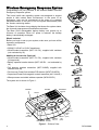
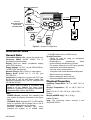
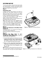
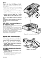
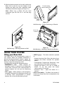
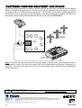
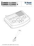
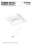
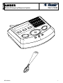
AMBER Wireless Emergency Response System DE7425AMU User's Guide 1 Wireless Emergency Response System Congratulations on your purchase of the wireless AMBER Personal Emergency Response system. This home health care signaling system was designed to support people in their natural home environment. In the event of an emergency, help can be summoned at the press of a pendant transmitter button. In the event of fire, the system automatically calls the Visonic monitoring station. The Base Unit includes a large display that shows the system status, the time and preprogrammed medication reminders. The Base Unit's rechargeable backup battery can provide up to 24 hours of operation. When AC power is restored, the backup battery is automatically recharged. AMBER MCT-212 RL What's Included Before you begin to set up your system, make sure you have all the necessary components. • Base Unit • 220VAC/110VAC to 12VAC transformer • Wrist/Pendant transmitter (MCT-212 RL), supplied with necklace (not evaluated by UL) MCT-430 RL MCT-241MD RL Additional Accessories (Optional) • Wrist/Pendant transmitter (MCT-211 RL), supplied with necklace (UL approved) • Battery operated smoke detector (MCT-430 RL – not evaluated by UL) • Fall detector pendant transmitter (MCT-241MD), supplied with necklace and clip • Pet-Immune PowerCode wireless PIR detector (NEXT K9-85 RL) • Supervised PowerCode magnetic contact transmitter (MCT-302N RL) • Microprocessor controlled wireless repeater (MCX-600 RL) NEXT K9-85 RL MCT-302N RL The system unit is shown in Figure 1. MCX-600 RL ANTENNA SPEAKER EMERGENCY BUTTON DISPLAY CALL BUTTON DIRECT LINK BUTTONS CHECK MICROPHONE BUTTON TROUBLE LED (red) POWER LED (green) STATUS LED (yellow) Figure 1 – External View 2 DE7425AMU PENDANT TRANSMITTERS MCT-211 RL TEL. LINE UP TO 29 WIRELESS DEVICES ( DETECTORS / TRANSMITTERS) PUBLIC TELEPHONE EXCHANGE MCT-241 MD RL SMOKE DETECTOR MCT-430 RL MOTION DETECTOR DOOR CONTACT REPEATER CENTRAL STATION NEXT K9-85 RL MCT-302N RL MCX-600 RL Figure 2 – System Configuration SPECIFICATIONS General Data Transmitter Battery Life: 3 years (for typical use) Frequency (MHz): 868.95, 433.92, 315 or according to local standards Display: Dual line, backlit 16-character display with 3 LED indicators. Supply Voltage: 12 VAC,1 A (via 220VAC/50Hz / 110VAC/60Hz transformer) Receiver Range: 600 ft (180 m) in open space Battery Pack: NI-MH 9.6 V, 1.8 Ah, type GP 0-9912-G. Compliance: Designed to comply with FCC part 68 and part 15, and UL 1637 Home Health Care Signaling Equipment. MCT-430 RL complies with UL 268 and UL 985. The system shall be installed in accordance with Chapter 2 of the National Fire Alarm Code, ANSI/NFPA 72 (National Fire Protection Association, Batterymarch Park, Quincy, MA 02269). LEDs: POWER (Green): Normally ON, indicating that your system is properly connected to the power outlet. TROUBLE (Red): Normally OFF. If LED flashes, there is a problem with the Base Unit or one of the devices (described on the display). STATUS (Yellow): Normally OFF, which indicates the system is in HOME mode. DE7425AMU FLASHES when unit is in AWAY mode. Special Functions: - Calling for help by using an emergency pendant transmitter - Speakerphone (hands-free) when communicating with Monitoring Center - The system supports up to 29 users (pendant transmitters and smoke detectors). - Two-way voice communication - Computer control and data download/upload - Remote control by telephone - Remote diagnostic and event log - Visual and audible announcements Physical Properties Operating Temperature: 32°F to 104°F (0°C to 40°C) Storage Temperature: -4°F to 140°F (-20°C to 60°C) Size: 9-13/16 x 7-1/4 x 2-5/16 in. (248 x 185 x 55 mm). Weight (AMBER only): 3 lb (1.35 kg) Color: Off-white Note: The monitoring station receiver is the SURGARD MLR2. 3 SYSTEM SETUP To set up your system, follow the steps below. After you complete steps 1 through 5, your system's Base Unit will automatically call the Monitoring Center to guide you through the rest of the set up. Step 1 Select Base Unit If possible, select a central location in your home for the Base Unit. This location should be in the area where you spend most of your time. The location should also enable an optimal signal reception range of 150 ft. for pendants and smoke detectors. The Base Unit can be placed on a table, desk, or counter. It also can be mounted on a wall. Make sure that the location you have selected is near an electrical outlet and a phone jack. Note: Certain remote areas of your residence may lie outside the reception range of the AMBER, resulting in the unit not being able to receive transmissions directly. In this case, a Repeater (MCX-600 RL) can be used to increase the AMBER reception range. Contact a Visonic representative for further details. Step 2 Rotate the Antenna on the Base Unit (Figure 3) Figure 3 – Base Unit with Raised Antenna The antenna helps your pendant(s) and detector(s) communicate with your Base Unit. Rotate the antenna to its utmost vertical position. Step 3 Connect the Base Unit∗ to your Telephone Line (Figure 4) The Base Unit communicates with your Monitoring Center through your telephone line. 1. Locate the phone jack on your wall where you want to connect your Base Unit. If a phone is already plugged into that jack, unplug it and connect it to the "PHONE" connector on the back of the Base Unit. Your telephone will still function normally. 2. There is a phone cord already connected to the "Wall Jack" on your Base Unit. Plug the other end of that phone cord into the phone jack on your wall. The Base Unit is now connected to your telephone line. Note: Be aware of other phone line services such as DSL. If DSL service is present on the phone line, you must install a filter. See Figure 4 for proper installation. ∗ 4 DSL FILTER For locations with DSL service. Figure 4 – Connecting Telephone Line to Base Unit For advanced phone connections see page 12. DE7425AMU Step 4 Plug in the Base Unit (Figures 5a/b) During normal operation, your Base Unit runs on electrical power. The power cord is looped around a bracket segment to provide strain relief against inadvertent pulling and disconnection of the power cord. 1. Loop the power cord around the bracket segment as shown in figure 5a. 2. Insert the small plug on the power cord into the "AC" connector on the Base Unit (see Figure 5b). 3. Connect the AC/AC adapter into a nearby electrical outlet. DO NOT USE AN OUTLET CONTROLLED BY A WALL SWITCH. Note: The AC/AC adapter is used as the disconnect device. When electrical power is supplied to the Base Unit, the green light on the front panel illuminates. Figure 5a – Looping the Power Cord Step 5 Base Unit is now connecting you to the Monitoring Center After installation, a Monitoring Center representative will begin speaking to you. When your Monitoring Center representative answers, you can hear them talking to you through the Base Unit. You can talk to the representative by speaking out loud. You do not need to use the phone. The Monitoring Center representative will guide you through the rest of the system setup. Figure 5b – Inserting Plug into Base Unit MOUNTING THE BASE UNIT The Base Unit can be located on a table (Figure 6), or on a wall (Figure 7). In both cases the Base Unit should be near an electrical outlet and phone line. Mounting the Base Unit on the Table 1. Insert the cabinet hangers into the holes in the position shown in Figure 6. 2. Place the Base Unit with the attached bracket on the table. OPTIONAL: Mounting the Base Unit on the Wall Figure 6 – Table Mounting 1. Rotate the bracket 180° before mounting on wall, as shown in Figure 7a. 2. Drill 3 holes on mounting wall and insert 3 screws into the bracket slots then tighten screws to secure bracket (see Figure 7b). DE7425AMU 5 3. With the bracket mounted on the wall, position the Base Unit so that the top two hangers of the bracket are fitted onto their respective holes followed by the bottom hanger (see Figure 7c). Note: Please use a Philips flat pan head screwdriver type AB P/N 6x1 in. and wall plug anchors. For wall mounting rotate the bracket 180º Correct bracket position Figure 7a Wall Mounting – Correct Positioning of Bracket HOLES FOR HANGERS Figure 7b Wall Mounting – Mounting Bracket on Wall Figure 7c Wall Mounting – Attaching Cabinet to the Bracket USING YOUR SYSTEM Using your Base Unit Your Base Unit is the communication center of your system. When your pendant transmitter or optional fall-detector/smoke detector signals the Base Unit, the Base Unit contacts your Monitoring Center to report the emergency event. Your Base Unit includes the following buttons. • EMERGENCY (red) – When pressed, an emergency alarm is reported to the Monitoring Center and a two-way voice communication is opened between the unit and the Monitoring Center. • CALL (gray) – When pressed, a non-emergency message is reported to the Monitoring Center and a two-way voice communication is opened between the unit and the Monitoring Center. 6 • • CHECK (gray) – This button should be pressed to: - Answer Incoming Calls. When the phone rings, pressing this button activates the speaker phone. - Acknowledge Programmed Reminders, such as confirming you have taken medication. - Change the status of the unit to HOME or AWAY. To do this, press this button continuously for 5 seconds. - Announce Time – press this button for 1 second. Direct Link (white) – The Base Unit includes 3 buttons for unique direct link, as described in the next section. DE7425AMU Using your Pendant Transmitter The pendant transmitter can be used to initiate an emergency call and also to answer incoming calls. • Pendant Activation - Your pendant transmitter lets you signal to the Base Unit from anywhere in your home when you need emergency assistance. You should wear your pendant transmitter whenever you are at home even in the shower or bath. Your pendant transmitter is waterproof. Your pendant transmitter can be activated by simply pushing its red button. Once pushed, a signal is sent from the pendant transmitter to the Base Unit and the red LED on the pendant transmitter illuminates. The Base Unit then calls the Monitoring Center and opens a two-way voice communication between the user and the Monitoring Center. The Base Unit's display shows CALLING FOR HELP together with the name and number of the activated pendant. If your phone is ringing, pressing the pendant's red button once will answer the incoming call. You can then talk over the unit's speakerphone. To end the speakerphone call and hang up, simply press the pendant button again. • Neckband - You can wear the pendant transmitter using the neckband. Slip the tab on the neckband into the slot on the pendant transmitter and fasten the tab. • Optional Wristband - Your pendant transmitter can also be used with an optional wristband. To make the pendant transmitter wristband smaller, slide the pendant transmitter towards the buckle. To make the wristband larger, slide the pendant transmitter away from the buckle. Calling for Emergency Assistance If you need emergency assistance, press the button on your pendant transmitter or press the large, red EMERGENCY button on your Base Unit. If you press the EMERGENCY button on the Base Unit, the display shows EMERGENCY BUTTON WAS PRESSED. The Base Unit calls your Monitoring Center and sends an emergency alarm. When your Monitoring Center representative answers, you can hear him or her talking to you through the Base Unit. If you have a phone connected to the Base Unit and want to use the phone to talk with the representative, let the representative know and the Monitoring Center will return your call. Trouble Trouble conditions are indicated by the red flashing LED and by the sounding of beeps, and are immediately reported to the Monitoring Center. Trouble messages are shown on the Base Station display until they are resolved. Pressing the CHECK button confirms the trouble condition and cancels the beeps. DE7425AMU The Base Unit continues to transmit trouble messages every eight hours until the problem is resolved. Changing System Status When the user wants to leave the premises, the unit status must be changed to AWAY mode. The CHECK button should be held down for 5 seconds. The unit announces and displays AWAY – REMINDERS OFF. In this state no medication reminders and no pendant checks will be announced. The unit's speaker is disabled and the yellow LED flashes. If the pendant transmitter button is pressed while in the AWAY mode, the unit will sound "EMERGENCY" and reports to the Monitoring Center. This initiates two-way communication through the speaker. In addition, any device that is alarmed while in AWAY mode immediately initiates a call to the Monitoring Center (as in HOME mode) and also initiates two-way communication. To return the status to HOME mode, hold down the CHECK button for 5 seconds. The unit's speaker will announce and display "HOME – REMINDERS ON". The yellow LED will turn off. Clock Adjustment To Set the Clock 1. To enter the clock adjustment mode, press the CHECK button three consecutive times. After each press, be sure to wait for the time announcement to complete before pressing again. The top line, assigned to the Month, will begin to flash. 01/15/2004 08:25:53 PM 2. Use Direct Link buttons 1 (scrolls up) and 2 (scrolls down) to set the current field value. 3. Press Direct Link button 3 to scroll to select other fields: month, day, year, hours, minutes, and seconds. 4. Press the Check button to set a new date or time value. Note: Press the Call (Escape) button at any time to return to normal operation mode. This does not affect current time/date settings. Direct link The direct link buttons function as follows: • The Base Unit dials the programmed telephone number stored in memory location 1, 2 or 3 and operates the unit as a speaker phone. • Used for scrolling between fields when setting the clock. • Used for adjusting the volume during two-way voice communication with incoming calls or for calls performed using the direct link buttons. Press direct link button 1 to increase the volume or direct link button 3 to decrease the volume. Programming of the direct link buttons is performed by the Visonic Monitoring Center. The stored telephone numbers may be modified at any time. 7 Note: The preprogrammed telephone number can be written on a label below the buttons using a pencil. The telephone number can easily be modified or erased using an ordinary pencil eraser. In the Event of Smoke (Smoke Detector – Optional) Your system can monitor up to 29 optional smoke detectors (purchased separately). If a smoke detector detects smoke, the smoke detector will sound its alarm and signal the Base Unit. The Base Unit calls the Monitoring Center to report a possible fire. Then the Monitoring Center representative answers, the situation is assessed, and the appropriate response is determined. In the Event that User Falls (Fall Detector - Optional) The fall detector is activated once the unit is tilted by more than 60° in any direction. The Base Unit will announce "Fall Detected" after 30 sec. The Base Unit will transmit an emergency alarm after an additional 30 sec has elapsed (60 sec after the fall detector is first tilted). If, during this time, the user restores the fall detector to its upright position, the unit will announce "Fall Device Upright – System OK". TESTING PROCEDURES The following are the necessary procedures for testing relevant system devices. User Test Mode There are two ways to enter User Test mode: • During every 2-way voice communication with the central station, the Base Unit automatically enters User Test mode once the operator uses the telephone line. • During a telephone conversation, the party at the other end of the telephone line must press **# in order to enter user test mode. When the call ends, the telephone line returns to normal mode. In the USER TEST mode, the Base Unit announces a verbal message upon reception of a transmission from an enrolled detector. This verbal message consists of two parts: Detector Name; and Signal Strength. In the Event that No Activity is detected (Motion Detector / Transmitter - Optional) The motion detector and door contact transmitter are used to monitor the user's activity. If no activity is detected by the enrolled transmitter(s) during a pre-defined amount of time, the AMBER will report an inactivity condition to the Monitoring Center, which will initiate a two-way voice communication. Inactivity time periods are defined remotely by the central station. Non-Emergency Services (CALL) The Visonic Monitoring Center provides nonemergency (concierge-type) services. When you press the CALL button, the Base Unit displays CALL WAS PRESSED. If NON EMERGENCY services are available to you, the Base Unit will contact the Monitoring Center and open a two-way voice communication. You can use the CALL button to speak to a Monitoring Center representative about your system. Because the call is non-emergency call, there might be a delay before the Monitoring Center representative responds. As long as the display shows CALL WAS PRESSED, you do not need to press the button again. A representative will begin speaking to you shortly. • Detector Name – the Base Unit will announce the detector type, for example, pendant, fall detector, smoke detector, and the detector's zone number. • Signal Strength – 3 beeps indicate "strong" signal strength; 2 beeps indicate "good" signal strength; 1 beep indicates "poor" signal strength; no beeps indicate that the Base Unit has failed to measure the signal strength for that transmission. Pendant transmitter Test Regular manual testing of your pendant(s) is an optional feature. If your installer has enabled pendant tests, then at the scheduled time, the unit will announce and display "Please Test Your Pendant". The panel will also display "Press Your Pendant" along with the pendants name. You must then press the pendant transmitter, whereby the unit will announce and display "Test Complete". MAINTAINING YOUR SYSTEM When a Pendant's Battery is Low When a pendant transmitter's button is pressed and its battery is low, the pendant transmitter flashes rapidly several times per second and the red light on the Base Unit flashes continuously until the 8 pendant's battery is replaced. The display shows LOW BATTERY and the pendant transmitter's name. Your system informs the Monitoring Center. Please contact your Visonic sales representative for information on battery replacement. DE7425AMU When a Smoke Battery is Low Detector's When a smoke detector's battery voltage is low, the smoke detector beeps every 35 seconds to alert you and will continue to beep until the detector's battery is replaced. The Base Unit's display shows LOW BATTERY and the smoke detector's name. Your system informs the Monitoring Center. The smoke detector's batteries should last at least one year. To replace the batteries, refer to the instructions provided with the smoke detector. TROUBLESHOOTING The following table provides a list of problems that may arise with the system together with possible solutions. PROBLEM DEFINITION SOLUTION The red light on the Base Unit is There is a problem. The Base Press the CHECK button to flashing and beeps are heard Unit informs your Monitoring silence the trouble beeps. Respond to the message on the Center. Base Unit's display. The display shows AC POWER No electrical power is being Check to see if there is a power FAILURE supplied to the Base Unit. The failure. Base Unit is running on backup If there has not been a power battery power. The Base Unit failure, make sure the power cord informs your Monitoring Center is connected securely to the Base (after two min.). Unit and the electrical outlet. The display shows TELEPHONE The unit does not detect that a Make sure the phone cord is LINE TROUBLE working phone line is present. connected securely to the Base Unit and to the phone jack on the wall. If the problem persists, report the problem to your Monitoring Center. The Base Unit beeps The Base Unit is malfunctioning. Press the CHECK button to continuously silence the trouble beeps. Contact your Monitoring Center. The display shows BASE UNIT The Base Unit's batteries are Batteries will be recharged when LOW BATTERY low. The Base Unit informs your AC power is restored. Monitoring Center. The display shows the device A pendant transmitter's or a Contact your Monitoring Center name and LOW BATTERY or smoke detector's battery is low. representative. The Base Unit informs your BATTERY TROUBLE Monitoring Center. You hear strange tones when Your Base Unit is trying to call Hang up so your system can using the phone your Monitoring Center. report a problem to the Monitoring Center. When it finishes you can use the phone. You hear noise interference The cordless phone might be If the cordless phone's base is when using your cordless phone picking up noise interference connected to the Base Unit, connect the phone to a phone from the Base Unit. jack away from the Base Unit. If the cordless phone's base is not connected to the Base Unit, move the phone's base farther away from the Base Unit. The clock blinks continuously The Base Unit has been reset. Refer to the section "Clock Adjustment". DE7425AMU 9 MISCELLANEOUS COMMENT The 315 MHz version of this device complies with Part 15 of the FCC Rules. Operation is subject to the following two conditions: (1) This device may not cause harmful interference, and (2) This device must accept any interference received, including interference that may cause undesired operation. The digital circuit of this device has been tested and found to comply with the limits for a Class B digital device, pursuant to Part 15 of the FCC Rules. These limits are designed to provide reasonable protection against harmful interference in residential installations. This equipment generates, uses and can radiate radio frequency energy and, if not installed and used in accordance with the instructions, may cause harmful interference to radio and television reception. However, there is no guarantee that interference will not occur in a particular installation. If this device does cause such interference, which can be verified by turning the device off and on, the user is encouraged to eliminate the interference by one or more of the following measures: – Re-orient or re-locate the receiving antenna. – Increase the distance between the device and the receiver. – Connect the device to an outlet on a circuit different from the one which supplies power to the receiver. – Consult the dealer or an experienced radio/TV technician. 1. This equipment, wireless emergency response system, model AMBER, complies with Part 68 of the FCC Rules and the requirements adopted by the ACTA. On the bottom panel of this equipment is a label, that contains among other information, a product identifier in the format US:VSOAL00BAMBER. If requested, this number must be provided to the telephone company. 2. This equipment is designed to be connected to the telephone network using an RJ-11 connector which complies with Part 68 rules and requirements adopted by ACTA and a properly installed RJ-31X connector. 3. If the AMBER causes harm to the telephone network, the telephone company will notify you in advance that temporary discontinuance of service may be required. If advance notice is not practical, you will be notified as soon as possible. Also, you will be advised of your right to file a complaint with the FCC if it is necessary. 4. The telephone company may make changes in its facilities, equipment, operations or procedures that could affect the operation of the equipment. If this occurs, the telephone company will provide advance notice in order for you to make necessary modifications to maintain uninterrupted service. 5. Connection to a telephone company providing coin service is prohibited. Connection to party lines service is subject to state tariffs. 10 DE7425AMU APPENDIX: HOME FIRE ESCAPE PLANNING The onset of a fire can often spread rapidly throughout your home, leaving you with little time to escape safely. Getting out of the house depends, largely, on advance warning from smoke detectors together with an advance planning strategy – namely, a home fire escape plan familiar to all members of your family and which has previously been put into practice. Perform the following steps: • Make preparations with members of your family to conduct an evacuation plan. • Draw a floor plan of your home, displaying two possible exit areas of each room, including windows. Don’t forget to mark the location of every installed smoke detector. • Test all smoke detectors periodically (this must be performed in a qualified testing laboratory), to ensure their serviceability. Replace batteries as required. • Make sure that everyone understands the escape plan and is able to recognize the sound emitted from the smoke alarm. Verify that the escape routes are clear and that doors and windows can be opened easily. • If windows or doors in your home have security bars, make sure that the bars have quick-release mechanisms on the inside, which, in the event of an emergency, can be opened immediately. Quick release mechanisms do not compromise your security, but increase the likelihood of safely escaping a home fire. • Practice the escape plan at least twice a year. It is important that all members of the family participate, especially children and grandparents. Allow children to master the fire escape planning procedure before holding a fire drill at night while they are asleep. The objective here is to perform a fire drill, and not to frighten the children, so informing the children of the fire drill before they go to bed can be as effective as a surprise drill. If children or others do not awaken promptly to the sound of the smoke alarm, or if there are infants or family members with mobility disabilities, make sure that someone is assigned to assist them in the fire drill and in the event of a real-life emergency. • Agree on an outside meeting place where everyone can meet once safely out of the house premises. Remember to get out of the house first, and then to call for help. Never go back inside the house until authorized by the fire department. • Ensure that all members of the family memorize the emergency phone number of the fire department. This will allow a member of the household to call for help from a cellular phone or from a neighbor’s home. • Be fully prepared for a real fire: when a smoke alarm sounds, get out of the house immediately and do not return to the house until authorized to do so by the fire department! • If you live in an apartment building, make sure that you are familiar with the building evacuation plan. In the event of a fire, use the stairs, never the elevator. Inform guests or visitors to your home about your family’s fire escape plan. When visiting other homes, ask the occupants about their escape plan, if they have one. If they do not, point out the importance of such a plan and offer to help them prepare one. This is particularly important when children attend “sleepovers” at friends' homes. Warning Owners Instructions Notice: Smoke detectors shall not be removed by anyone except by occupants. GENERAL RF DISCLAIMER Due to the varying range of wireless systems, Visonic and its partners are not held liable if the system does not receive or process the RF transmitted communications signals as specified. Radio Waves pass through wood and plastic with very little attenuation (loss of signal strength). The same radio waves pass through concrete, earth and living matter with greater loss of signal strength and reflect off of metal. To better ensure the reception, initial and regular range testing procedures must be followed. This device complies with part 15 of the FCC rules. DE7425AMU 11 CUSTOMER PREMISES EQUIPMENT AND WIRING The REN is used to determine the number of devices that may be connected to a telephone line. Excessive RENs on a telephone line may result in the devices not ringing in response to an incoming call. In most but not all areas, the sum of RENs should not exceed five. To be certain of the number of devices that may be connected to a line, as determined by the total RENs, contact the local telephone company. The REN of an alarm system is part of the product identifier that has the format US:VSOAL00BAMBER. 1 2 DSL FILTER For locations with DSL service RJ-31X JACK 8 7 TELCO FROM STREET 3 6 4 5 RJ-31X CORD TO WALL JACK Note: For whole house line seizure with DSL service present on the phone line, you must install a filter. It is suggested to use the DSL alarm filter model Z-A431PJ31X manufactured by Excelsus Technologies, or equivalent. This filter simply plugs into the RJ-31X jack and allows alarm reporting without breaking the internet connection. W.E.E.E. Product Recycling Declaration For information regarding the recycling of this product you must contact the company from which you orignially purchased it. If you are discarding this product and not returning it for repair then you must ensure that it is returned as identified by your supplier. This product is not to be thrown away with everyday waste. Directive 2002/96/EC Waste Electrical and Electronic Equipment. R VISONIC LTD. (ISRAEL): P.O.B 22020 TEL-AVIV 61220 ISRAEL. PHONE: (972-3) 645-6789, FAX: (972-3) 645-6788 VISONIC INC. (U.S.A.): 65 WEST DUDLEY TOWN ROAD, BLOOMFIELD CT. 06002-1376. PHONE: (860) 243-0833, (800) 223-0020. FAX: (860) 242-8094 VISONIC LTD. (UK): FRASER ROAD, PRIORY BUSINESS PARK, BEDFORD MK44 3WH. PHONE: (0870) 730-0800 FAX: (0870) 730-0801 INTERNET: www.visonic.com VISONIC LTD. 2005 AMBER USER GUIDE DE7425AMU (REV. 1, 04/05) 12 DE7425AMU