1
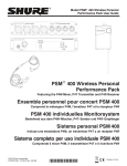
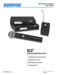
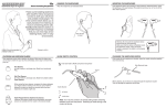
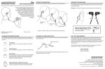
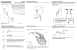
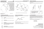
Model PSM® 700 User Guide
PSM® 700
Wireless Personal Monitor System
User Guide
Système de retour personnel sans fil
Guide de l’utilisateur
Drahtloses individuelles Monitorsystem
Bedienungsanleitung
Sistema de monitor personal inalámbrico
Guía del usuario
Radiosistema di controllo personale
Guida all’uso
27E8659 (Rev. 5)
©2008 Shure Incorporated
Printed in U.S.A.
This symbol indicates that dangerous voltage
constituting a risk of electric shock is present within
this unit.
This symbol indicates that there are important
operating and maintenance instructions in the
literature accompanying this unit.
WARNING!
USING THIS SYSTEM AT EXCESSIVE VOLUMES CAN CAUSE PERMANENT HEARING DAMAGE.
USE AS LOW A VOLUME AS POSSIBLE.
In order to use this system safely, avoid prolonged listening at excessive sound pressure levels. Please use the following guidelines established by
the Occupational Safety Health Administration (OSHA) on maximum time exposure to sound pressure levels before hearing damage occurs.
90 dB SPL at 8 hours
95 dB SPL at 4 hours
100 dB SPL at 2 hours
105 dB SPL at 1 hour
110 dB SPL at ½ hour
115 dB SPL at 15 minutes
120 dB SPL — avoid or damage may occur
It is difficult to measure the exact Sound Pressure Levels (SPL) present at the eardrum in live applications. In addition to the volume setting on the
PSM, the SPL in the ear is affected by ambient sound from floor wedges or other devices. The isolation provided by the fit of quality earpieces is also
an important factor in determining the SPL.
Here are some general tips to follow in the use of this product to protect your ears from damage.
•
Turn up the volume control only far enough to hear properly.
•
Ringing in the ears may indicate that the gain levels are too high. Try lowering the gain levels. Have your ears checked by an audiologist on a
regular basis. If you experience wax buildup in your ears, stop using the system until an audiologist has examined your ears.
•
Wipe the ear molds with an antiseptic before and after use to avoid infections. Stop using the earphones if they are causing great discomfort or
infection.
! IMPORTANT SAFETY INSTRUCTIONS !
1.
2.
3.
4.
5.
6.
7.
8.
9.
10.
11.
READ these instructions.
KEEP these instructions.
HEED all warnings.
FOLLOW all instructions.
DO NOT use this apparatus near water.
CLEAN ONLY with dry cloth.
DO NOT block any ventilation openings. Install in accordance with the manufacturer's instructions.
DO NOT install near any heat sources such as radiators, heat registers, stoves,
or other apparatus (including amplifiers) that produce heat.
DO NOT defeat the safety purpose of the polarized or grounding-type plug. A
polarized plug has two blades with one wider than the other. A grounding type
plug has two blades and a third grounding prong. The wider blade or the third
prong are provided for your safety. If the provided plug does not fit into your outlet, consult an electrician for replacement of the obsolete outlet.
PROTECT the power cord from being walked on or pinched, particularly at plugs,
convenience receptacles, and the point where they exit from the apparatus.
ONLY USE attachments/accessories specified by the manufacturer.
12.
USE only with a cart, stand, tripod, bracket, or table
specified by the manufacturer, or sold with the
apparatus. When a cart is used, use caution when
moving the cart/apparatus combination to avoid
injury from tip-over.
13.
UNPLUG this apparatus during lightning storms or when unused for long periods of
time.
REFER all servicing to qualified service personnel. Servicing is required when the
apparatus has been damaged in any way, such as power-supply cord or plug is damaged, liquid has been spilled or objects have fallen into the apparatus, the apparatus
has been exposed to rain or moisture, does not operate normally, or has been
dropped.
DO NOT expose the apparatus to dripping and splashing. DO NOT put objects filled
with liquids, such as vases, on the apparatus.
The MAINS plug or an appliance coupler shall remain readily operable.
The airborne noise of the apparatus does not exceed 70dB (A).
Apparatus with CLASS I construction shall be connected to a MAINS socket outlet
with a protective earthing connection.
To reduce the risk of fire or electric shock, do not expose this apparatus to rain or
moisture.
Do not attempt to modify this product. Doing so could result in personal injury
and/or product failure.
14.
15.
16.
17.
18.
19.
20.
Quickstart
P7T Transmitter Setup
Ñ
3.
1. Connect the transmitter to a power outlet using the supplied power cord.
NOTE: Keep wall plug or rear power cord connection readily accessible. To
completely remove power to the unit, unplug from wall or detachable rear power
cord connection.
1.
2.
2. Attach the supplied antenna to the ANTENNA OUT BNC connector.
3. Connect an audio source, such as a mixer, to the audio inputs of the transmitter.
You can use both input jacks or choose either one for a mono source.
NOTE: All inputs are phantom power protected up to 60 VDC.
4. Set the PAD switch to either +4 dB or –10 dB depending on the signal level from
the audio source.
4.
5. Turn on the transmitter.
6. Set the SOURCE switch to MONO if you are using only one input. Otherwise set
it to STEREO/MixMode.
7. Set the GROUP switch UP to group 1.
8. Set the CHANNEL dial to an unused channel.
NOTE: See Selecting Channels.
8.
6.
9.
7. 5.
9. Power on the audio source and adjust the level control until the LEDs are in the
–3 dB to +3 dB range.
P7R Receiver Setup
10. Attach the antenna to the ANTENNA connector. Use the red dot to align the threads.
10.
11. Insert a 9V alkaline battery.
15.
16.
12. Set the DIP switches (See Dip Switches)
13. Set the channel to the same one as the transmitter.
14. Set the balance control to the center detent position.
15. Plug in the earphones and insert the earphones into your ears.
16. Turn the receiver on by rotating the volume dial clockwise past the click.
NOTE: If you do not hear anything, check the RF LED on the transmitter to make
sure it is receiving the radio signal from the transmitter.
14.
13.
12.
11.
Refer to the Troubleshooting section of this manual if you encounter any problems.
LOWER THE VOLUME before troubleshooting the problem.
English - 1
Components
P7T Transmitter with rack-mounting hardware and detachable
PA715 antenna
P7R Body-Pack Receiver with detachable PA710
antenna
SCL3 or SCL5 Earphones with foam
and flex-tip inserts
Features
• UHF operation.
• Stereo or MixMode™ control for custom monitor mixes.
• 32 user-selectable frequencies per system.
• Up to 16 compatible frequencies for 16 different mixes.
• Frequency compatible with all Shure Wireless systems
(country dependent).
• MPX Stereo audio transmission.
• Switchable high-frequency boost on P7R.
• +4 dBu and –10 dBV input level select switch on P7T.
• Electronically balanced, combined 1/4-in. and XLR
connectors on P7T can be used with balanced or unbalanced
outputs.
• Volume and Balance dials on the P7R Receiver.
2 - English
• Internal linear power supply on P7T, switchable between
120 VAC and 230 VAC.
• Peak transmitter modulation limiter with fixed threshold and
modulation limit indicators.
• Loop out connectors on P7T for multiple mix setups and easy
installation.
• Tone-Key squelch.
• Half-rack chassis on P7T complete with mounting hardware.
• All metal construction on P7T and P7R.
• Headphone monitor on P7T for local listening.
• Earphones reduce ambient sound levels by sealing off the
ear canal
Controls and Connectors
P7T Transmitter
Front Panel
Input Control (INPUT). Controls the input level to the transmitter modulator. For optimum sound quality, adjust this control to keep the
INPUT meter in the –3 dB to +3 dB range.
Stereo Input Meters. Indicates the modulation level of the radio signal.
Important: When the LIM (limit) LEDs illuminates, the system is overdriven. Reduce the input level.
SOURCE Switch. Set the SOURCE switch to MONO if you are using only one input. Otherwise, set it to STEREO/MixMode.
Earphone Volume Control (VOLUME). Adjusts the volume at the transmitter’s earphone connector. This control does not affect the
sound level at the receiver.
Earphone Connectors: 1/4 in phone and 3,5 mm (1/8 in) mini.
Left=tip, right=ring, ground=sleeve. Note that only one of these outputs can be used at a time.
Channel Select Control (CHANNEL).
See Selecting Channels.
Channel Group Switch (GROUP).
See Selecting Channels.
Power Button (POWER).
Rear Panel
Power Connector and Fuse. Connect the transmitter to a power outlet using the supplied power cord. The fuse is located in the bottom
drawer.
LOOP OUT Connectors — 1/4 in phone, balanced. See the LOOP Applications section of this manual.
INPUT PAD Switch. Set the PAD switch to either +4 dB or –10 dB depending on the signal level of the audio source you are connecting to
the transmitter’s inputs. (Refer to the output specifications for the audio source.)
Input Connectors (LEFT/CH. 1 and RIGHT/CH. 2). Connect to balanced or unbalanced outputs. Accepts both 1/4-inch phone or male
XLR connectors. Either connector can be used for mono input.
Antenna Connector (ANTENNA OUT). 50 Ω, BNC connenctor. Attach the supplied antenna, or, if you are rackmounting the transmitter,
see Front Mounting the Antenna.
English - 3
P7R Receiver
Balance Control. In stereo mode, this controls the left/right balance. In MixMode™, it controls the relative level of the two transmitter
inputs.
Earphone Connector. 3,5 mm (1/8-in.) phone jack connects to the earphones.
Left=tip, right=ring, ground=sleeve.
Low Battery LED (LOW BATT). Illuminates when the battery has approximately 45 minutes of operating time remaining, depending on
the volume.
Power LED (PWR ON). Illuminates when the power is ON and the battery is good.
Power Switch and Volume Control (VOLUME).
Antenna and Connector. Attach the antenna to the antenna connector. Use the red dot to align the threads.
RF Signal LED (RF ON). Illuminates when the P7R is receiving a signal from the transmitter.
Battery Compartment. Accepts one 9-volt battery. Open the door by pressing the latches on both sides and pulling.
DIP Switches. See DIP Switches or the label on the inside cover of the battery door.
Channel Selector. See Selecting Channels.
Reversible Belt Clip. Belt clip can be removed and installed in the reverse position so the antenna points down when the body-pack is
worn.
DIP Switches
1—Channel Group
Group 1
3—Equalization
High Boost (Offers more high-end response: 6 dB boost at
10 kHz)
Group 2
Normal (Flat)
2—Balance Control
MixMode
Stereo
4—Limiter
On
Off
IMPORTANT: The limiter responds to unexpected signal peaks. It does not prevent long-term exposure to high SPL
levels. This limiter is optimized for Shure E-Series earphones. The maximum limited SPL may be different for
other earphones. Do not switch the limiter off unless you are using an external limiter.
4 - English
Selecting Channels
The PSM700 system offers a total of 32 channels. These are split into two groups: Group 1 (channels 1–16)
and Group 2 (channels 17–32). Change channels if you encounter interference or need to operate more than
one system at a time.
• The transmitter and receiver must be set to the same group and channel.
• Multiple systems must use different channels.
• Use the supplied screwdriver to rotate the channel control.
Channel
Group
Channel
Group
Channel Scan Mode
If you have difficulty finding a clear channel, use the receiver’s Channel Scan Mode. Normally, the receiver mutes if it
does not detect a signal from the transmitter. In this mode, the receiver remains unmuted, so you can listen for interference.
1. Turn off all PSM700 transmitters (leave other wireless systems on).
2. Set the receiver to group 1 (DIP switch 1 UP) and channel 1 (rotary channel select).
3. Lower the volume on the receiver to a minimal level and insert the earphones.
4. Turn on the receiver and, within 5 seconds of power up, flip DIP switch 1 down and up again.
5. Listen to all the channels in groups 1 and 2:
• Clear channels will produce pure, uninterrupted white noise.
• Any noises like clicks or buzzes indicate interference from another device.
6. Turn the receiver off and on again to return to normal operating mode. Select the channel with the least interference.
Monitoring the Performers’ Mixes
When setting up multiple systems, use an extra receiver to check and monitor each transmitter. Set the group
and channel controls on the extra receiver to whichever transmitter you want to monitor. If necessary, adjust the
balance control to check for proper stereo or MixMode operation.
Troubleshooting
PROBLEM
SOLUTION
No sound at the Receiver
•
•
•
•
•
•
Make sure the transmitter is plugged in and powered on.
Listen to the headphone monitor on the transmitter to check the audio source input.
Make sure the transmitter and receiver are set to the same channel and group.
Make sure the earphone is plugged into the receiver.
Make sure receiver is on and the battery is good.
Make sure the receiver and transmitter antennas are correctly attached.
Short Receiver Range
•
•
•
•
•
Make sure all antennas are fully inserted into the jacks.
Maintain line-of-sight between transmitter and receiver.
Try a different group and channel setting.
Check for television channel interference.
Make sure the PA715 antenna is not remote mounted.
Receiver sounds fuzzy or distorted
•
•
•
•
Make sure no other transmitters are operating on your frequency.
Make sure transmitter input level is 0 dB, ±3 dB.
Listen to the headphone monitor on the transmitter to check the audio source input.
Try to maintain a minimum of 10 ft. between transmitter antennas and receiver when using
multiple transmitters.
Low audio output at the receiver
earphones
•
Make sure transmitter input level is 0 dB, ±3 dB.
If not, switch the transmitter pad to the –10 dBV position.
English - 5
Operating Modes
This section illustrates the three basic modes of operation. For additional installations, including those for
multiple systems, see the LOOP Applications section.
NOTE: Although a mixing console is shown as the audio source in the following diagrams, you can use any
balanced or unbalanced outputs at LINE level (for example, CD players, DAT machines, and microphone
preamplifiers). For best results, use LINE level audio signals.
Stereo
Use this setup when outputs 1 and 2 from the mixer are the left and right channels of a stereo mix. The left
channel goes to the left earphone, and the right channel goes to the right earphone. The balance control on the
receiver moves the stereo image left and right.
1.
ÑÑ
Ñ
Ñ
ÑÑ
Ñ
ÑÑÑÑÑ
0
4
C
3.
8
2.
1. Connect the mixer outputs to the transmitter.
2. Set the SOURCE switch on the P7T front panel to STEREO.
3. Set DIP switch 2 of the P7R Receiver to STEREO.
MixMode™ Operation
Use this setup when outputs 1 and 2 from the mixer are different mono mixes. Each mix goes to both
earphones. The performer uses the balance control on the receiver to make one mix louder than the other. The
total volume remains equal in both ears.
1.
ÑÑÑ
ÑÑ
2.
1
1
2
3.
1. Connect the mixer outputs to the transmitter.
2. Set the SOURCE switch on the P7T transmitter to STEREO/MixMode.
3. Set DIP switch 2 on the receiver to MixMode.
6 - English
2
Mono
Use this setup when there is only one output from the mixer.
Ñ
1.
2.
1. Connect the mixer to either the Left/CH.1 or Right/CH.2 input of the transmitter.
2. Set the SOURCE switch on the transmitter to MONO.
NOTE: The setting of Dip switch 2 on the receiver has no effect in this setup.
LOOP Applications
Use the LOOP OUT L (left) and R (right) outputs to send a copy of the audio signal going into the transmitter to
other devices. Shown here are a few examples of the many applications for the LOOP outputs.
NOTE: The input level control and the input pad do not affect the level of the LOOP signals.
Stereo for Multiple Systems
Use the LOOP OUT connectors to send one stereo signal
from the mixing console to multiple P7T or P6T wireless
transmitters. This frees up sends on the mixing console for other
uses.
ÑÑ ÑÑ
Set up each system for stereo control as shown in the Stereo
Control section. Connect the first transmitter to the mixer.
Connect the next transmitter to the first transmitter’s LOOP
outputs. Form a chain using all the transmitters in your
installation.
English - 7
MixMode for Multiple Systems
Solo Mixes
Some performers need to hear more of their
own voice or instrument, while others want to
hear more of the band. With this setup, each
performer hears a combination of the whole band
and their own instrument, and they can use the
receiver’s balance control to create the desired
mix of the two.
Band Mix
ÑÑÑÑÑÑÑÑÑÑ
Setup each system for MixMode. From the
mixing console, send a mix of the whole band to
input 2 of the first transmitter. Connect input 2 of
the next transmitter to the LOOP OUT R output of
the first transmitter. Continue the chain with all
the transmitters. Next, create solo mixes for each
performer using the auxiliary outputs of the
mixing console. Send these mixes to input 1 of
each performer’s transmitter.
Floor Monitors
Connect the LOOP OUT connectors to the amplifier for
onstage loudspeakers. The P7R and the onstage monitors
will have the same audio.
ÑÑÑ
ÑÑ
ÑÑÑ
ÑÑ
Recording Devices
To record a performance, connect the LOOP outputs
to the inputs of a tape deck, DAT, or other recording
device.
ÑÑÑÑ
ÑÑ
Ñ
8 - English
Specifications
SYSTEM
Power
9 V battery (alkaline recommended),
4–6 hours (volume dependent)
Audio Output Connector
3.5 mm Stereo (Left = tip, Right = ring, Ground = sleeve)
Minimum Load Impedance
16 Ω
Net Weight
0.23 kg (0.52 lbs.)
Overall Dimensions
27.18 mm X 64.52 mm X 85.09 mm
(1.070 in X 2.540 in X 3.350 in)
RF Carrier Frequency Range
524-952 MHz (Available frequencies vary, depending on applicable
regulations in the country where the system is used)
Operating Range
90 m (300 ft.), under optimum environmental conditions
Audio Frequency Response
50 to 15k Hz (+0, –3 dB @1 kHz); earphone dependent
Image Rejection
80 dB typical
Spurious Rejection
80 dB typical
Total Harmonic Distortion (@1 kHz)
0.8% typical (Ref. ±35 kHz deviation)
Modulation
FM ±35 kHz deviation (nominal), MPX Stereo
Channel Separation
35 dB typical
Signal-to-Noise Ratio
80 dB typical (A-weighted)
Operating Temperature
–7° C to +49° C (+20° F to 120° F)
NOTE: Electrical safety approval is based on a maximum ambient
temperature of 35°C.
Battery Life
4–6 hours, volume dependent
Polarity
P7T audio inputs to P7R audio outputs: Non-inverting
XLR: pin 2 positive with respect to pin 3
1/4 in TRS: Tip positive with respect to ring
P7T TRANSMITTER
RF Output Power
100 mW (+18.5 dBm) typical conducted, U.S.A. and Canada
(varies with other countries)
Modulation Limiter
Internal peak limiter (>10:1 compression)
Antenna
External whip, 50 Ω BNC connector
Power Requirements
P7T: 90–120 VAC, 50/60 Hz
EP7T: 220–240 VAC, 50/60 Hz
NOTE: This product is not disconnected from the mains power
supply when the power switch is in the OFF position.
Current
115 mA maximum at 120 VAC
55 mA maximum at 230 VAC
Fuse
P7T: 90–120 VAC, 160 mA/250 V (SLO-BLO®)
EP7T: 220–240 VAC, 80 mA/250 V time delay
5mm X 20mm
Dimensions
44.5 mm X 196.8 mm X 241.3 mm
(1 3/4 in X 7 3/4 in X 9 1/2 in.)
Net Weight
1.497 kg (3 lb, 4.8 oz.)
P7R RECEIVER
RF Sensitivity
0.7 µV typical
Squelch Threshold
2 µV typical
Antenna Input Impedance
50 Ω typical
Antenna
External, threaded connector
P7T Audio Inputs (LEFT/CH.1 and RIGHT/CH.2)
Configuration
Actual Impedance
Nominal Input Level
Maximum Input Level
Pin Assignments
Phantom Power Protection?
XLR
Electronically Balanced
20 kΩ
+4 dBu (+4 input level)
–10 dBV (–10 input level)
+25 dBu (+4 input level)
+13 dBu (–10 input level)
Pin 1 = ground
Pin 2 = hot
Pin 3 = cold
Yes, up to 60 VDC
1/
4-inch
Phone Jack
Electronically balanced
20 kΩ
+4 dBu (+4 input level)
–10 dBV (–10 input level)
+25 dBu (+4 input level)
+13 dBu (–10 input level)
Tip = hot
Ring = cold
Sleeve = ground
Yes, up to 60 VDC
P7T Outputs (L/R LOOP)
Configuration:
Actual Impedance:
Nominal Output Level:
Maximum Output Level:
Pin Assignments:
Phantom Power Protection?
Electronically Balanced
20 kΩ
+4 dBu (+4 input level)
–10 dBV (–10 input level)
+25 dBu (+4 input level)
+13 dBu (–10 input level)
Tip = hot
Ring = cold
Sleeve = ground
Yes, up to 60 VDC
English - 9
Certification
P7T: Certified to FCC Parts 74, FCC ID DD4P7T. DD4P7TB Certified in Canada by IC to RSS-123.
UL and cUL LISTED to UL813 and CSA C22.2 No. 1.
TÜV DENAN
Certified to J 60065.
EP7T: Meets essential requirements of European R&TTE Directive 99/5/EC, eligible to bear CE marking. Type approved to EN 300 422 Parts 1 and 2.
Meets requirements of EMC Standard EN 301 489 Parts 1 and 9. VDE GS Certified to EN 60065.
P7R: Approved under the Declaration of Conformity (DoC) provision of FCC Part 15. Certified in Canada by IC to RSS-123. Meets essential
requirements of European Union R&TTE Directive 99/5/EC, eligible to bear CE marking. Meets requirements of EMC Standard EN 301 489
Parts 1 and 9.
This Radio Equipment is intended for use IN MUSICAL PROFESSIONAL ENTERTAINMENT AND SIMILAR APPLICATIONS.
NOTE: This Radio apparatus may be capable of operating on some frequencies not authorized in your region. Please contact your national authority to
obtain information on authorized frequencies for wireless microphone products in your region
Licensing: A ministerial license to operate this equipment may be required in certain areas. Consult your national authority for possible requirements.
Shure Transmitter Model P7T may be used in the countries and frequency ranges listed in in the Appendix.
FCC Statement. The P7R Receiver complies with Part 15 of the FCC rules. Operation is subject to the following two conditions: (1) this device does not
cause harmful interference, and (2) this device must accept any interference received, including interference that may cause undesired operation.
Licensing Statement. A user license may be required for operation. Contact the communications authority in your country for more information.
Modifications to Approved Equipment. Changes or modifications not expressly approved by Shure Incorporated could affect compliance with
telecommunications standards, thereby voiding the user’s authority to operate this product.
Voltage Selection
WARNING
Voltages in this equipment are hazardous to life. No user-serviceable parts inside. Refer all
servicing to qualified service personnel.
The safety certifications of the P7T/EP7T do not apply when the operating voltage is
changed from the factory setting.
P7T and EP7T transmitters can be internally modified to operate at either 120 Vac or 230 Vac as follows:
1. Disconnect the P7T/EP7T from the AC power source.
2. Remove the eight Phillips head screws securing the top cover.
3. Locate Voltage Selector switch SW4 adjacent to power transformer T1 and, using a screwdriver, turn the center rotor
to the desired position:
For 120 V operation, turn it to the 115 V position.
For 230 V operation, turn it to the 230V position.
4. Locate fuse and remove it. Replace it with the proper fuse:
For 120 V operation, use a 160 mA, 250 V, slow-blow fuse.
For 230 V operation, use a 80 mA, 250 V, time delay fuse.
Fuse Part Numbers
Fuse Type
80 mA, 250 V
time delay
160 mA, 250 V
SLO-BLO
Shure Part No.
80H380
80K258
Part No.
Schurter
.034.3106
Littelfuse®
218.160
5. Replace the power cord with the proper power cord:
For 120 V operation, use an IEC appliance connector on the equipment end and a mains connector suitable for 115 V
operation on the other.* (Shure part #95A8389.)
For 230 V operation, use an IEC appliance connector on the equipment end and a CEE 7/7 (“Schuko”) mains
connector on the other.* (Shure part #95A8247.)
* For systems requiring other mains connectors, obtain a power cord with an IEC 320 type mating connector for connection to the P7T, and an
appropriate plug on the other end for connection to the mains. The supplied cord uses Harmonized IEC Cordage with color coding as follows:
Brown = Line, Blue = Neutral, Green/Yellow = Ground.
10 - English
Accessories
Furnished
Optional
Body-Pack Antenna (524-750 MHz) ..................................... 90A8964
Body-Pack Antenna (770-870 MHz) ..................................... 90B8964
Transmitter Antenna (524-750 MHz) .................................... 95A8699
Transmitter Antenna (770-870 MHz) .................................... 95A8621
Rack Mount Kit
.................................................................PA745
61 cm (2 ft) Coaxial Cable (RG-58/U)...................................... UA802
Bulkhead Adapter ............................................................. 95A8994
SCL3/SCL5 sleeve assortment with cleaning tool .............. 90XJ1371
Antenna Combiner ................................................... PA760 (120 VAC)
................................................... PA770 (120 VAC)
............................................PA821 (100-240 VAC)
.................................................PA765E (240 VAC)
.................................................PA770E (240 VAC)
Unidirectional Antenna ...........................................................PA805WB
3.3 m (10 ft.) Coaxial Antenna Cable (BNC connector) ........... PA725
Bag of 20 Foam Ear Sleeves (yellow)...................................... PA750
Triple-Flange Ear Sleeves (2) .................................................. PA755
Bag of 10 Flex-Tip Ear Sleeves (small).................................. PA756S
Bag of 10 Flex-Tip Ear Sleeves (medium) ............................ PA756M
Bag of 10 Flex-Tip Ear Sleeves (large) .................................. PA756L
PA805WB Unidirectional Antenna
This unidirectional, remote-mountable, wide-band transmitting antenna provides wireless coverage in a cardioid
pattern. Use the PA805WB to secure a line-of-sight transmission path from the transmitter to the receiver when the
actual transmitters are obscured. Also, since the PA805WB has some gain (due to its directivity), it is useful when
covering long distances.
PA821, PA760, PA765, PA770 Antenna Combiners
Reduce rack clutter and improve performance by combining up to four transmitters into a single
antenna. These internally powered, half-rack units make transportation and setup easy, and they
significantly reduce interference between transmitters by lowering the intermodulation distortion
(IMD) level. Select among the different models to match the frequency range of your systems.
(Please note that PA700 antenna combiners cannot be cascaded to each other.)
PA760
PSM700s
P6HW Hardwired Body Pack
Ñ
Ñ
Some performers, such as drummers and keyboard players, benefit less from the on-stage mobility
that wireless systems offer. For these users, hardwired monitor systems, like the Shure P6HW, offer the
same features of a wireless system at a lower cost. The P6HW also includes an input pad, for increased
dynamic range, and an input peak indicator to alert the user when levels are too high.
SCL Earphones
Shure offers a variety of earphones to fit your needs. Designed exclusively for PSM systems,
they deliver superior sound quality. For the added comfort of a precise fit, custom earmolds are
also available for SCL3 model earphones.
English - 11
Rack Mounting
WARNING:
Do not torque the screws too tightly, or the chassis
may be damaged.
Single Unit
Dual-Mounted Units
IMPORTANT:
Attach the link bars so the recessed horizontal holes face out
and the threaded and unthreaded vertical holes align.
Dual Mounting with Other Shure Products
Shure P7T and P6T transmitters and SC and LX receivers can be dual-mounted interchangeably (although
the front panels for different products may not align evenly). For each side, use the rack ear that came with that
product. The link bars are universal.
Front Mounting the Antenna
When rack mounting units, use the supplied cable and bulkhead adapter to front mount the antenna. This
prevents other cables from becoming entangled in the antenna and can greatly reduce RF interference.
12 - English
English - 13
APPENDIX
ANNEXE
TABLE 1
Country Code
Code de Pays
Lander-Kurzel
Código de País
Codice del Paese
P7T-H3
(524 - 554 MHz)
ANHANG
TABLEAU 1
P7T-L2
(632 - 662 MHz)
TABELLE 1
P7T-HF
(722 - 746 MHz)
APENDICE
TABLA 1
APPENDICE
TABELLA 1
P7T-P5
(722 - 746 MHz)
P7T-MN
(800 - 830 MHz)
P7T-KE
(842 - 865 MHz)
USA
524 - 554z*
632 - 662*
722 - 746*
*
*
*
CAN
524 - 554*
632 - 662*
722 - 746*
*
*
*
A
524 - 554*
632 - 662*
722 - 746*
722 - 746*
800 - 830*
842 - 865*
B
524 - 554*
632 - 662*
722 - 746z*
722 - 746*
800 - 830
842 - 865*
CH
524 - 554*
632 - 662*
722 - 746*
722 - 746*
800 - 830*
842 - 865*
CY
*
*
*
*
*
*
CZ
524 - 554*
632 - 662*
722 - 746*
722 - 746*
800 - 830*
*
842 - 865*
D
524 - 554*
632 - 662*
722 - 746*
722 - 746*
800 - 830*
DK
*
*
*
*
800 - 820*
863 - 865*
E
524 - 554*
632 - 662*
722 - 746z*
722 - 746*
800 - 830*
842 - 865*
EST
524 - 554*
632 - 662*
722 - 746*
722 - 746*
800 - 830*
842 - 865*
F
*
*
*
722-746*
*
863 - 865*
FIN
*
*
*
*
800,1 - 819,9*
863 - 865*
GB
524 - 554*
632 - 662z*
722 - 746z*
722 - 746*
*
842 - 865*
GR
524 - 554*
632 - 662*
722 - 746*
722 - 746*
800 - 830*
*
I
524 - 554*
632 - 662*
722 - 746*
722 - 746*
*
863 - 865*
H
524 - 554*
632 - 662*
722 - 746*
722 - 746*
800 - 830*
*
IRL
524 - 554*
632 - 662*
722 - 746*
722 - 746*
800 - 830*
842 - 865*
L
524 - 554*
632 - 662*
722 - 746*
722 - 746*
800 - 830
842 - 865z*
LT
524 - 554*
632 - 662*
722 - 746*
722 - 746*
800 - 830*
*
LV
*
*
*
*
*
*
M
524 - 554*
632 - 662*
722 - 746*
722 - 746*
*
842 - 865*
N
*
*
*
*
800 - 820*
863 - 865*
NL
524 - 554*
632 - 662*
722 - 746*
722 - 746*
800 - 830*
842 - 865*
842 - 865*
P
524 - 554*
632 - 662*
722 - 746*
722 - 746*
800 - 830*
PL
524 - 554*
632 - 662*
722 - 746*
722 - 746*
800 - 830
*
S
*
*
*
*
800 - 814 *
863 - 865*
SK
*
*
*
*
*
*
SLO
524 - 554*
632 - 662*
722 - 746*
722 - 746*
800 - 830*
*
All Other Countries
*
*
*
*
*
*
Tous les autres pays
Alle anderen Länder
Demás países
Tutti gli altri Paesi
*Please contact your national authority for information on available legal frequencies for your area, maximum transmitter output power, and legal use of the equipment.
*Se mettre en rapport avec les autorités compétentes pour obtenir les informations sur les fréquences autorisées disponibles localement, le puissance de sortie HF de
l'émetteur, et sur l'utilisation autorisée du matériel.
*Für Informationen bezüglich der für Ihr Gebiet verfügbaren gesetzlich zugelassenen Frequenzen und der mösglichen Abstrahl-Leistung sowie der gesetzlichen Bestimmungen für den Einsatz der Geräte setzen Sie sich bitte mit der zuständigen örtlichen Behörde in Verbindung.
*Comuníquese con la autoridad nacional para obtener información en cuanto a las frecuencias legales disponibles, la potencia RF de salida del transmisor, y usos legales
del equipo en su área.
*Rivolgersi alle autorità competenti per ottenere informazioni relative alle frequenze autorizzate nella propria regione, la potenza RF di uscita di trasmettitore, e alle norme
che regolano l'uso di questo apparecchio.
Appendix - 1
EU DECLARATION OF CONFORMITY
We,
of
Shure Incorporated
5800 Touhy Avenue
Niles, Illinois, 60714-4608 U.S.A.
Phone: (847) 600-2000
Web: www.Shure.com
Declare under our sole responsibility that the following product
Model: P7R
Description: Personal Stereo UHF Receiver
conforms to the essential requirements and other relevant previsions of the R&TTE Directive
(1999/5/EC).
The product complies with the following product family, harmonized or national standards:
EN 301 489-1 V1.4.1 (2002-08)
EN 301 489-9 V1.2.1 (2002-08)
EN 300 422-1 V1.2.2 (2000-08)
EN 300 422-2 V1.1.1 (2000-08)
The technical documentation is kept at:
Shure Incorporated, Corporate Quality Engineering Division
SHURE Europe GmbH, EMEA Approval
Manufacturer: Shure Incorporated
Signed: __________________________________ Date: 3 March 2006
Name and Title: Craig Kozokar, EMC Project Engineer, Corporate Quality Engineering Division
European Representative: SHURE Europe GmbH
Signed: __________________________________ Date: 3 March 2006
Name and Title: Wolfgang Bilz, Dipl. Ing. (FH), EMEA Approval
SHURE Europe GmbH
Headquarters Europe, Middle East & Africa
Wannenäcker Str. 28
D-74078 Heilbronn, Germany
Phone: +49 - (0)7131 - 7214 - 0
Fax: +49 - (0)7131 - 7214 - 14
EU DECLARATION OF CONFORMITY
We,
of
Shure Incorporated
5800 Touhy Avenue
Niles, Illinois, 60714-4608 U.S.A.
Phone: (847) 600-2000
Web: www.Shure.com
Declare under our sole responsibility that the following product
Model: P7T
Description: Personal Stereo UHF Transmitter
conforms to the essential requirements and other relevant previsions of the R&TTE Directive
(1999/5/EC).
The product complies with the following product family, harmonized or national standards:
EN 301 489-1 V1.4.1 (2002-08)
EN 301 489-9 V1.2.1 (2002-08)
EN 300 422-1 V1.2.2 (2000-08)
EN 300 422-2 V1.1.1 (2000-08)
IEC 60065:1998
EN61000-3-2:2000 Amendment A1:1998; A2:1998; A14:2000
EN 61000-3-3 Amendment A1:2001
The technical documentation is kept at:
Shure Incorporated, Corporate Quality Engineering Division
SHURE Europe GmbH, EMEA Approval
Manufacturer: Shure Incorporated
Signed: __________________________________ Date: 25 September 2007
Name and Title: Craig Kozokar, EMC Project Engineer, Corporate Quality Engineering Division
European Representative: SHURE Europe GmbH
Signed: __________________________________ Date: 25 September 2007
Name and Title: Wolfgang Bilz, Dipl. Ing. (FH), EMEA Approval
SHURE Europe GmbH
Headquarters Europe, Middle East & Africa
Wannenäcker Str. 28
D-74078 Heilbronn, Germany
Phone: +49 - (0)7131 - 7214 - 0
Fax: +49 - (0)7131 - 7214 - 14
ii
6+85(,QFRUSRUDWHGKWWSZZZVKXUHFRP
8QLWHG6WDWHV&DQDGD/DWLQ$PHULFD&DULEEHDQ
:7RXK\$YHQXH1LOHV,/86$
3KRQH86)D[,QW¶O)D[
(XURSH0LGGOH(DVW$IULFD
6KXUH(XURSH*PE+3KRQH)D[
$VLD3DFLILF
6KXUH$VLD/LPLWHG3KRQH)D[