1
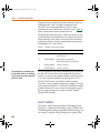
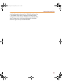
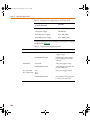
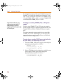
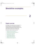
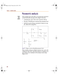
Pspug.book Page 459 Tuesday, May 16, 2000 1:17 PM
Mixed analog/digital
simulation
15
Chapter overview
This chapter describes how PSpice A/D runs mixed
analog/digital simulations and includes the following
sections:
•
Interconnecting analog and digital parts on page 15-460
•
Interface subcircuit selection by PSpice on page 15-461
•
Specifying digital power supplies on page 15-466
•
Interface generation and node names on page 15-471
Note This entire chapter describes features
that are not included in PSpice.
Pspug.book Page 460 Tuesday, May 16, 2000 1:17 PM
Chapter 15 Mixed analog/digital simulation
Interconnecting analog and
digital parts
Prior to simulation, netlisting translates the part instances
and nets defined in your schematic into parts connected
by nodes. The standard simulation netlist contains a flat
view of the circuit. (With this release, you can create
hierarchical simulation netlists as well.) PSpice A/D
extracts the definitions for all parts modeled as
subcircuits, viewing parts as a collection of primitive parts
and node connections.
The digital primitives that make up a digital part
determine the way that PSpice A/D processes an
analog/digital interface to that part. Specifically, the I/O
model for each digital primitive connected at the interface
gives PSpice A/D the necessary information.
PSpice A/D recognizes three types of nodes: analog
nodes, digital nodes, and interface nodes. The node type
is determined by the types of parts connected to it. If all of
the parts connected to a node are analog, then it is an
analog node. If all of the parts are digital, then it is a digital
node. If there is a combination of analog and digital parts,
then it is an interface node.
PSpice A/D automatically breaks interface nodes into one
purely analog and one or more digital nodes by inserting
one or more analog/digital interface subcircuits.
PSpice A/D also automatically connects a power supply
to the interface subcircuit to complete the generation of
the interface.
To view simulation results at an analog/digital interface
in your schematic using the graphical waveform analyzer:
460
•
Place a marker on the appropriate interface net. The
additional nodes created by PSpice A/D remain
transparent.
•
View results in PSpice A/D by selecting traces from
the output variable list (from the Trace menu, choose
Pspug.book Page 461 Tuesday, May 16, 2000 1:17 PM
Interface subcircuit selection by PSpice
Add Trace). If you use this approach, note the names
PSpice A/D generates for the new nodes.
To find out more, see Interface
generation and node names on
page 15-471.
Interface subcircuit selection by
PSpice
Analog-to-digital (AtoD) and digital-to-analog (DtoA)
interface subcircuits handle the translation between
analog voltages/impedances and digital states, or
vice-versa. The main component of an interface subcircuit
is either a PSpice N part (digital input: digital-to-analog)
or a PSpice O part (digital output: analog-to-digital).
PSpice N and O parts are neatly packaged into interface
subcircuits in the model library. The standard model
library shipped with your Orcad software installation
includes interface subcircuits for each of the supported
logic families: TTL, CD4000 series CMOS and high-speed
CMOS (HC/HCT), ECL 10K, and ECL 100K. This frees
you from ever having to define them yourself when using
parts in the standard library.
Note
That’s the letter O, not the numeral zero.
If you are creating custom digital parts in
technologies other than those provided in
the standard model library, you may need
to create your own interface subcircuits.
To search for particular parts in the standard Orcad libraries, see
the online PSpice Library List.
Every digital primitive comprising the subcircuit
description of a digital part has an I/O model describing
its loading and driving characteristics. The name of the
interface subcircuit actually inserted by PSpice A/D is
specified by the I/O model of the digital primitive at the
interface. The I/O model has parameters for up to four
analog-to-digital (AtoD) and four digital-to-analog
(DtoA) subcircuit names.
You can choose among four interface levels of subcircuit
models, depending on the simulation accuracy you need.
In some cases you may need more accurate simulations of
the input/output stages of a digital part, while in other
cases, a simpler, smaller model is enough.
461
Pspug.book Page 462 Tuesday, May 16, 2000 1:17 PM
Chapter 15 Mixed analog/digital simulation
Digital parts provided in the standard libraries only use
interface levels 1 and 2. With the exception of the
HC/HCT series (described below), levels 3 and 4
reference the same subcircuits as levels 1 and 2. Table 41
below summarizes the four interface levels.
The difference between levels 1 and 2 only occurs in the
AtoD interfaces, described below. In all cases, the level 1
DtoA interface is the same as the level 2 DtoA interface,
except that the level 2 DtoA interface does not generate
intermediate R, F, and X levels..
Table 41
The elaborate model is noticeably slower
than the simple model, so you should only
use it if you are using a power supply level
other than 5.0 volts.
Interface subcircuit models
Level
Subcircuits
Definition
1
AtoD1/DtoA1
AtoD generates intermediate R, F,
and X levels
2
AtoD2/DtoA2
AtoD does not generate
intermediate R, F, and X levels
3
AtoD3/DtoA3
(same as level 1)
4
AtoD4/DtoA4
(same as level 2)
The Orcad libraries provide two different DtoA models in
the HC/HCT series: the simple model and the elaborate
model. You can use the simple model by specifying level
1 or 2, the elaborate model by specifying level 3 or 4.
The HC/HCT level 1 and 2 DtoA models produce
accurate I-V curves given a fixed power supply of 5.0 volts
and a temperature of 25°C. The level 3 and 4 DtoA models
produce accurate I-V curves over the acceptable range of
power supply voltages (2-6 volts), and they include
temperature derating.
Level 1 interface
The level 1 AtoD interface generates intermediate logic
levels (R, F, X) between the voltage ranges VILMAX and
VIHMIN (specific voltages depend on the technology you
are using). A steadily rising voltage on the input of the
462
Pspug.book Page 463 Tuesday, May 16, 2000 1:17 PM
Interface subcircuit selection by PSpice
AtoD will transition from 0 to R at VILMAX and from R to
1 at VIHMIN. The F level is output for steadily falling
voltages in a similar manner. The X level is produced if the
input voltage starts in the threshold region or doubles
back into a previously crossed threshold.
463
Pspug.book Page 464 Tuesday, May 16, 2000 1:17 PM
Chapter 15 Mixed analog/digital simulation
This behavior may not be appropriate when
the input rise and fall times are long, or
when the input voltage never leaves the
threshold region. If this is the case, you
may want to use the level 2 interface.
Level 1 (the default) strictly maps logic levels onto the
changing input voltage. The exact switching voltage is
assumed to be anywhere between VILMAX and VIHMIN
due to temperature or power supply variations. Thus, it
provides more accurate, less optimistic results.
Level 2 interface
You can avoid simulations that get bogged
down with the greater detail of R, F, and X
states around these oscillations. You may
want to specify level 2 on only those parts
for which this behavior is critical to a
successful simulation. This is described in
Setting the default A/D interface
below.
464
The level 2 AtoD interface transitions directly from 0 to 1
and 1 to 0 without passing through intermediate R, F, or X
levels. An exact switching voltage is assumed (again, the
specific voltage depends on the technology you are
using). It provides a more optimistic, and therefore less
accurate, response than level 1. Level 2’s behavior is
appropriate when the input voltage oscillates around the
threshold voltage.
Pspug.book Page 465 Tuesday, May 16, 2000 1:17 PM
Interface subcircuit selection by PSpice
Setting the default A/D interface
For mixed-signal simulation, you can select the AtoD and
DtoA interface level circuit-wide and on individual part
instances.
•
To select the default interface level circuit-wide, select
one of the four Default A/D interfaces in the Digital
Setup dialog. Part instances whose IO_LEVEL
property is set to 0 will use this value.
•
You can override the circuit-wide default on an
individual part by specifying an IO_LEVEL property
from 1 to 4, where:
1:
AtoD1 and DtoA1 (default)
2:
AtoD2 and DtoA2
3:
AtoD3 and DtoA3
4:
AtoD4 and DtoA4
For example, you can tell the simulator to use the level 2
interface subcircuits for a 7400 part by setting the
IO_LEVEL property to 2. All other part instances continue
to use the circuit-wide setting. By default, IO_LEVEL is set
to 0, which tells the simulator to use the circuit-wide level
defined in the digital portion (DC Sweep analysis) of the
Simulation Settings dialog box.
465
Pspug.book Page 466 Tuesday, May 16, 2000 1:17 PM
Chapter 15 Mixed analog/digital simulation
Specifying digital power supplies
Digital power supplies are used to power interface
subcircuits that are automatically created by PSpice A/D
when simulating analog/digital interfaces. They are
specified as follows:
If you use custom digital parts created in
technologies other than those provided in
the standard model library, you may need
to create your own digital power supplies.
•
PSpice A/D can instantiate them automatically.
•
You can create your own digital power supplies and
place them in your design.
When using parts from the standard libraries in your
design, you can usually have PSpice A/D automatically
create the necessary digital power supply.
Because digital power supplies are used only by
analog/digital interface subcircuits, digital power
supplies are not needed for digital-only designs. Orcad
recommends avoiding placing a power supply to a
digital-only design because it may increase simulation
time and memory usage.
Default power supply selection by PSpice A/D
When PSpice A/D encounters an analog/digital
interface, it creates the appropriate interface subcircuit
and power supply according to the I/O model referenced
by the digital part. The I/O model is specific to the digital
part’s logic family. The power supply provides reference
or drive voltage for the analog side of the interface.
By default, PSpice A/D inserts one power supply
subcircuit for every logic family in which a digital
primitive is involved with an analog/digital interface.
These power supply subcircuits create the digital power
and ground nodes that are the defaults for all parts in that
family. If multiple digital primitives from the same logic
family are involved with analog/digital interfaces, one
instance of the power supply subcircuit is created with all
primitives connected to the power supply nodes.
466
Pspug.book Page 467 Tuesday, May 16, 2000 1:17 PM
Specifying digital power supplies
Table 42 summarizes the default node names and values.
For instance, TTL power supplies have a default value of
5.0 volts at analog/digital interfaces.
Table 42
Default digital power/ground pin connections
Logic family
Digital power/
ground pin properties
TTL
PSPICEDEFAULTNET (PWR)
PSPICEDEFAULTNET (GND)
CD4000
PSPICEDEFAULTNET (VDD)
PSPICEDEFAULTNET (VSS)
ECL 10K
PSPICEDEFAULTNET (VEE)
PSPICEDEFAULTNET (VCC1)
PSPICEDEFAULTNET (VCC2)
ECL 100K
PSPICEDEFAULTNET (VEE)
PSPICEDEFAULTNET (VCC1)
PSPICEDEFAULTNET (VCC2)
Default digital power/ground nodes
$G_DPWR (5.0 volts)
$G_DGND (0 volts)
$G_CD4000_VDD (5 volts)
$G_CD4000_VSS (0 volts)
$G_ECL_10K_VEE (-5.2 volts)
$G_ECL_10K_VCC1 (0 volts)
$G_ECL_10K_VCC2 (0 volts)
$G_ECL_100K_VEE (-4.5 volts)
$G_ECL_100K_VCC1 (0 volts)
$G_ECL_100K_VCC2 (0 volts)
The PSPICEDEFAULTNET pin properties have the same
default values as the digital power and ground nodes
created by the default power supply. These node
assignments are passed from the part instance to the
digital primitives describing its behavior, connecting any
digital primitive affected by an analog connection to the
correct power supply.
The default I/O models and power supply
subcircuits are found in DIG_IO.LIB. The
four default power supplies provided in the
model library are DIGIFPWR (TTL),
CD4000_PWR (CD4000 series CMOS),
ECL_10K_PWR (ECL 10K), and
ECL_100K_PWR (ECL 100K).
Creating custom digital power supplies
Each digital part model has optional digital power and
ground nodes that you can use to specify custom power
supplies. To do this, use one of the digital power supplies
listed in Table 43 below in your design and redefine the
digital power supply nodes.
When creating custom power supplies, you
can refer to the power supply definitions in
DIG_IO.LIB for examples of power supply
subcircuit definitions.
467
Pspug.book Page 468 Tuesday, May 16, 2000 1:17 PM
Chapter 15 Mixed analog/digital simulation
Table 43
Digital power supply parts in SPECIAL.OLB
Part type
(PSpice A/D X model)
Part name
CD4000 power supply
CD4000_PWR
TTL power supply
DIGIFPWR
ECL 10K power supply
ECL_10K_PWR
ECL 100K power supply
ECL_100K_PWR
The properties relevant to creating custom power supplies
are shown in Table 44.
Table 44
Part name
Property
Description
CD4000_PWR
VOLTAGE
CD4000 series CMOS power
supply voltage
PSPICEDEFAULTNET
CD4000 series CMOS hidden
power supply pins for VDD
and VSS
VOLTAGE
TTL power supply voltage
PSPICEDEFAULTNET
TTL hidden power (PWR) and
ground (GND) pins
VEE
VCC1
VCC2
ECL power supply voltages
PSPICEDEFAULTNET
ECL hidden power supply pins
for VEE, VCC1 and VCC2
DIGIFPWR
ECL_10K_PWR
ECL_100K_PWR
468
Digital power supply properties
Pspug.book Page 469 Tuesday, May 16, 2000 1:17 PM
Specifying digital power supplies
To create a custom digital power supply
1
Place the appropriate power supply part listed in
Table 43 in your design (by logic family).
2
Rename the power supply power and ground pins
(PSPICEDEFAULTNET properties).
3
Reset the power supply power and ground voltages as
required.
4
For any digital part instance that uses the power
supply, set its appropriate PSPICEDEFAULTNET pin
properties to the power and ground pins created by
the secondary power supply.
Note This procedure applies to all logic
families.
Overriding CD4000 power supply voltage
throughout a design
Designs using CD4000 parts often require power supply
voltages other than the default 5.0 volts supplied by the
standard CD4000_PWR power supply part. If needed, you
can override the power supply voltage for all CD4000
parts in a design.
The default power supply nodes used by CD4000 parts
are named $G_CD4000_VDD and $G_CD4000_VSS as
created by the power supply subcircuit CD4000_PWR.
This supply defaults to 5.0 volts. You can override the
voltage across these two nodes by defining values for the
parameters named CD4000_VDD and CD4000_VSS that
are referenced by the CD4000_PWR subcircuit definition.
To change the CD4000_PWR power supply to 12 volts,
referenced to ground:
1
Place an instance of the PARAM pseudopart from
SPECIAL.OLB.
2
Create a new PARAM property as follows:
CD4000_VDD = 12.0V
DC4000_VSS is left at its default of 0 volts.
If the reference voltage also needs to be reset, the same
method can be used to define the CD4000_VSS parameter
469
Pspug.book Page 470 Tuesday, May 16, 2000 1:17 PM
Chapter 15 Mixed analog/digital simulation
by setting this property of the same PARAM instance. For
example, if you want the supplies to go between -5 volts
and +5 volts (a difference of 10 volts), set CD4000_VSS to
-5V and CD4000_VDD to +10V; as a result, CD4000_VDD
is 10 volts above CD4000_VSS, or +5 volts.
Designs with TTL and ECL parts rarely
require secondary power supplies. If
needed, however, you can use this
procedure to add a secondary power supply
for TTL and ECL parts.
Creating a secondary CD4000, TTL, or ECL power
supply
Designs using CD4000, TTL, or ECL parts may require
power supply voltages in addition to the default 5.0 volts
supplied by the standard CD4000_PWR power supply
part.
To create a secondary power supply for any one of the
CD4000, TTL, or ECL technologies, you must place the
appropriate power supply part and create user-defined
nodes with a new voltage value.
To create and use a secondary CD4000 power supply with nodes
MY_VDD and MY_VSS and a voltage of 3.5 volts:
1
Place the CD4000_PWR power supply and modify the
appropriate pin properties as follows:
VOLTAGE = 3.5V
PSPICEDEFAULTNET = MY_VDD
PSPICEDEFAULTNET = MY_VSS
2
Select a CD4000 part in the schematic to which the new
power supply should apply, then change the
appropriate pin properties as follows:
PSPICEDEFAULTNET = MY_VDD
PSPICEDEFAULTNET = MY_VSS
470