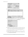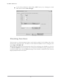
1
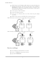
COMET SYSTEM
www.cometsystem.cz
P8610 intelligent thermometer
with PoE
P8631 intelligent 3-channel transducer
with PoE
USER MANUAL
IE-SNC-P86xx-02
© Copyright: COMET System, Ltd.
Is prohibited to copy and make any changes in this manual, without explicit agreement of
company COMET System, Ltd. All rights reserved.
COMET System, Ltd. makes constant development and improvement of their products.
Manufacturer reserves the right to make technical changes to the device without previous
notice. Misprints reserved.
Manufacturer is not responsible for damages caused by using the device in conflict with
this manual. To damages caused by using the device in conflict with this manual can not be
provide free repairs during the warranty period.
This user manual describes device with firmware version 4-5-5.x. For devices with older
firmware version 4-5-1.x please read manual IE-SNC-P86xx-01.
2
IE-SNC-P86xx-02
Table of contents
Introduction........................................................................................................................................................ 4
General safety rules ..................................................................................................................................... 4
Device description and important notices ............................................................................................... 5
Getting started.................................................................................................................................................... 6
What is needed for operation .................................................................................................................... 6
Mounting the device.................................................................................................................................... 6
Device settings ............................................................................................................................................. 7
Checking functions ...................................................................................................................................... 9
Device setup .....................................................................................................................................................10
Setup using web interface .........................................................................................................................10
Setup using TSensor software .................................................................................................................17
Factory defaults ..........................................................................................................................................17
Communication protocols .............................................................................................................................19
Website ........................................................................................................................................................19
SMTP – sending e-mails ...........................................................................................................................19
SNMP ..........................................................................................................................................................20
Modbus TCP ..............................................................................................................................................21
SOAP ...........................................................................................................................................................22
Syslog ...........................................................................................................................................................23
SNTP ...........................................................................................................................................................23
Troubleshooting...............................................................................................................................................24
I forgot the device IP address..................................................................................................................24
I can not connect to the device ...............................................................................................................24
Error or n/a is displayed instead the measured value .........................................................................25
Error2 is displayed on all channels instead the measured value.........................................................25
I forgot the password for setup ...............................................................................................................25
Factory defaults ..........................................................................................................................................25
Technical specifications ..................................................................................................................................26
Dimensions .................................................................................................................................................26
Basic parameters ........................................................................................................................................27
Operating terms .........................................................................................................................................28
End of operation .......................................................................................................................................29
Technical support and service .................................................................................................................29
Preventive maintenance ............................................................................................................................29
Optional accessories ........................................................................................................................................30
3
IE-SNC-P86xx-02
1
Chapter
Introduction
This chapter provides basic information about device. Before starting please read
this manual carefully.
P8610 Intelligent Thermometer and P8631 Transducer are used to measure temperature or
relative humidity. Temperature can be displayed in °C or °F. Relative humidity have unit
%RH. Communication with the device is realized via Ethernet network. Device can be
powered from external power supply adapter or by using power over Ethernet – PoE.
P8610 Thermometer has compact design and measures the temperature in place of
installation. To P8631 Transducer is possible connect up to three probes. Temperature or
humidity probes are available as optional accessories.
General safety rules
The following summary is used to reduce the risk of injury or damage the device.
To prevent injury, please follow instructions in this manual.
The device can be services only by a qualified person. The device contains no
serviceable parts inside standard means.
Don’t use the device, if it doesn’t work correctly. If you think, that the device is
not working correctly, let check it by qualified service person.
Don’t disassemble the device. It’s forbidden to use the device without the cover. Inside the
device can be a dangerous voltage and may be risk of electric shock.
Use only the appropriate power supply adapter according to manufacturer specifications
and approved according to relevant standards. Make sure, that the adapter does not have
damaged cables or covers.
Connect the device only to network parts approved according to relevant standards. Where
power over Ethernet is used, the network infrastructure must be compatible with IEEE
802.3af standard.
Connect and disconnect the device properly. Don’t connect or disconnect Ethernet cable
or probes, if the device is powered.
4
IE-SNC-P86xx-02
The device may be installed only in prescribed areas. Never expose the device to higher or
lower temperatures than is allowed. The device has not improved resistance to moisture.
Protect it from dripping or splashing water and do not use at areas with condensation.
Don’t use device in explosive environments.
Don’t stress the device mechanically.
Device description and important notices
This chapter contains informations about basic features. Also there are
important notices concerning to functional safety.
Values from the device can be read using an Ethernet connection. The following formats
are supported:
Web pages with user changeable look and XML files
Modbus TCP protocol
SNMPv1 protocol
SOAP protocol
The device can also be used to check measured values and if the limit is exceeded, device
sends warning messages. Possible ways to sending warning messages:
Sending e-mails up to 3 e-mail addresses
Sending SNMP traps up to 3 configurable IP addresses
Displaying the alarm status on web page
Sending messages to Syslog server
The device setup can be made by the TSensor software or web interface. TSensor software
can be free downloaded from the manufacturer’s website. Also you will find there latest
firmware for your device. Do not upload to your device firmware which is not designed for
it. Unsupported firmware can damage your device.
If you want to use PoE, you must use PoE switch compatible with IEEE 802.3af standard.
As a low cost solution can be recommended Repotec switch RP-PE8T/4.
Reliability of warning messages delivering (e-mail, trap, syslog), depends on
actual availability of necessary network services. The device should not be used
for critical applications, where malfunction could cause to injury or loss of
human life. For highly reliable systems, redundancy is essential. For more
information please see standard IEC 61508.
Never connect the device directly to the Internet. If it is necessary connect the
device to the Internet, properly configured firewall must be used. Firewall can
be partially replaced with the NAT.
5
IE-SNC-P86xx-02
2
Chapter
Getting started
Here you can find informations necessary to put newly purchased equipment to
operation. This procedure is only informative.
What is needed for operation
To install the unit you need to the following equipment. Before installation check if it’s
available.
P8610 Thermometer or P8631 Transducer
power supply adapter 5V/250mA or switch with PoE. Before using the device
is necessary to decide which way of powering will be used.
RJ45 LAN connection with appropriate cable
free IP address in your network
for P8631 Transducer up to 3 temperatures probes type DSTR162/C,
DSTGL40/C, DSTG8/C or relative humidity probe DSRH
Mounting the device
check if the equipments from previous chapter are available
install the latest version of TSensor software. This software is used to all
device settings.
TSensor software can be free downloaded from the manufacturer’s website.
Software can be also supplied on CD. Device configuration can be made
using web interface. For web configuration is not TSesnor software necessary.
contact your network administrator to obtain following informations for the
connection to the network:
IP address:
Gateway:
Netmask:
_____._____._____._____
_____._____._____._____
_____._____._____._____
6
IE-SNC-P86xx-02
check if there is no IP address conflict when you connect the device into
network for the first time. The device has from factory set the IP address to
192.168.1.213. This address must be changed according to informations from
the previous point. When you installing several new devices, connect them to
the network one after another.
connect probes to P8631 Transducer
connect the Ethernet connector
if the power over Ethernet (PoE) is not used, connect the power adapter
5V/250mA
LEDs on LAN connector should blink after connecting the power
P8610 Thermometer connection (power supply adapter, Power over Ethernet):
P8631 Transducer connection (power supply adapter, Power over Ethernet):
Device settings
run configuration software TSensor on your PC
switch to an Ethernet communication interface
press button Find device...
7
IE-SNC-P86xx-02
the window shows all available devices on your network
click to Change IP address to set new address according to network
administrator instructions. If your device is not listed, then click Help! My
device wasn’t found! Then follow the instructions. MAC address is on
product label. The device is factory set to IP 192.168.1.213.
gateway may not be entered if you want to use the device only in local
network. If you set the same IP address which is already used, the device will
not work correctly and there will be collisions on the network. If the device
detects a collision of IP address then reboot is performed automatically.
after changing IP address device is restarted and new IP address is assigned.
Restart of the device takes about 10 seconds.
connect to device using TSensor software and check the measured values. If
P8631 Transducer values are not displayed, it’s necessary to find probes using
button Search probes (Find probes).
8
IE-SNC-P86xx-02
set the other parameters (alarm limits, SMTP server, etc.). Settings are saved
after click on button Save changes.
Checking functions
The last step is to check measured values on the device website. In the address bar of the
web browser, enter the device IP address. If the default IP address was not changed, then
insert http://192.168.1.213.
Displayed web page lists actual measured values. If the web pages are disabled, you can see
text Access denied. If the measured value exceeds the measurement range or probe is not
correctly installed, then is shown Error message. If the channel is switched off, the web site
displayed n/a instead of the value.
9
IE-SNC-P86xx-02
3
Chapter
Device setup
This chapter describes basic device configuration. There is a description of
settings using web interface.
Setup using web interface
Device can be setup using web interface or TSensor software. Web interface can be
managed by the web browser. Main page will be shown when you insert device address
into address bar of your web browser. There you find actual measured values. Page with
history graphs is shown when you click to tile with actual values. Access to device setup is
possible via tile Settings.
10
IE-SNC-P86xx-02
General
Device name can be changed using item Device name. Measured values are stored into
memory according History storage interval field. After changing of this interval all
history values will be cleared. Changes must be confirmed by Apply settings button.
Network
Network parameters can be obtain automatically from DHCP server using option Obtain
an IP address automatically. Static IP address is configurable via field IP address. It is
not necessary setup Default gateway while you use device inside one subnet only. Option
Standard subnet mask sets network mask automatically according A, B or C network
class. Subnet mask field must be set manually, when network with non standard range is
used. Periodic restart interval enables to restart device after selected time since device
start.
11
IE-SNC-P86xx-02
Alarm limits
For each measurement channel is possible to set upper and lower limits, time-delay for
alarm activation (0 – 65535s) and hysteresis for alarm clearing.
Example of setting the limit to the upper alarm limit:
In Point 1 the temperature exceeded the limit. From this time, the time-delay is counting.
Because at point 2 the temperature dropped below the limit value before the time delay
expired, alarm was not set.
In Point 3 the temperature has risen over limit again. During the time-delay the value does
not drop below the set limit, and therefore was in Point 4 caused alarm. At this moment
were sent e-mails, traps and set alarm flag on website, SNMP and Modbus.
The alarm lasted up to Point 5, when the temperature dropped below the set hysteresis
(temperature limit – hysteresis). At this moment was active alarm cleared and e-mail send.
When alarm occurs, alarm messages will be sent. In case of power failure or device reset
(e.g. changing the configuration) will new alarm state evaluated and new alarm messages
will be send.
12
IE-SNC-P86xx-02
Channels
Channel can be enabled or disabled for measuring using item Enabled. Channel can be
renamed (max. 14 characters) and it is possible select unit of measured value according
connected probe type. When channel is not used, it is possible copy to it one of other
channels – option Clone channel. This option is not available at fully occupied device.
Find sensors button starts searching for connected probes. All changes must be
confirmed using Apply settings button. History values are cleared after changing of
channel settings.
SOAP protocol
SOAP protocol can be enabled by option SOAP protocol enabled. IP address of the
destination http server is configurable via SOAP server IP address filed. For setup of
destination server port can be used option SOAP server port. Target place of the http
server can be set via SOAP server target place. Device send SOAP message according
selected Sending interval. Option Send SOAP message when alarm occurs sends
message when an alarm on channel occurs or alarm is cleared. These SOAP messages are
sent asynchronously to selected interval.
13
IE-SNC-P86xx-02
Email
Email sending enabled option allows email features. It is necessary set address of the
SMTP as IP address into SMTP server IP address field. Default port of the SMTP server
can be changed using item SMTP server port. SMTP authentication can be enabled using
SMTP authentication option. When authentication is enabled Username and Password
must be set.
For successfully email sending it is necessary insert Email sender address. This address is
usually same as username of the SMTP authentication. Into fields Recipient 1 to
Recipient 3 it is possible set address of email recipients. Option Short email enable
sending emails in short format. This format is usable when you need to forward emails into
SMS messages.
When option Alarm email repeat sending interval is enabled and there is active alarm on
channel, then emails with actual values are sent repeatedly. Info email sending interval
option enables sending emails at selected time interval. CSV history file can be sent
together with the repeat/info emails. This feature can be enabled by Alarm and Info
emails attachment option.
It is possible to test email function using button Apply and test. This button save a new
settings and send a testing email immediately.
14
IE-SNC-P86xx-02
Modbus a Syslog protocols
ModbusTCP and Syslog protocol settings are configurable via menu Protocols. Modbus
server is enabled by default. Deactivation is possible via Modbus server enabled option.
Modbus port can be changed via Modbus port field. Syslog protocol can be enabled using
item Syslog enabled. Syslog messages are sent to IP address of the Syslog server - field
Syslog server IP address.
SNMP
For reading values via SNMP it is necessary to know password - SNMP read community.
SNMP Trap can be delivered up to three IP address - IP address of the Trap recipient.
SNMP Traps are sent at alarm or error state on the channel. Trap feature can be enabled by
option Trap enabled.
15
IE-SNC-P86xx-02
Time
Time synchronization with SNTP server can be enabled by Time synchronization
enabled option. IP address of the SNTP is necessary to set into SNTP server IP address
item. SNTP time is synchronized at UTC format, and due to be necessary set
corresponding time offset - GSM offset [min]. Time is synchronized every 24 hours by
default. Option NTP synchronization every hour decrease this synchronization interval
to one hour.
WWW and security
Security features can be enabled by the Security enabled option. When security is enabled
it is necessary to set administrator password. This password will be required for device
settings. When secured access is required even to actual values reading it is possible to
enable User account only for viewing. Port of the www server can be changed from the
default value 80 using filed WWW port. Web pages with actual values are refreshed
according to Web refresh interval field.
16
IE-SNC-P86xx-02
Setup using TSensor software
TSensor software is an alternative to web configuration. Some less important parameters
are configurable only by the TSensor software.
Parameter MTU size can reduce size of the Ethernet frame. Lowering of this size can
solve some communication problems mainly with Cisco network infrastructure. Sensor
software can set offset of values at temperature probes. At DSRH humidity probe is
possible set correction of the humidity and temperature.
Factory defaults
Factory defaults button set the device into factory configuration. Network parameters (IP
address, Subnet mask, Gateway) are left without changes.
Network parameters are changed while you close jumper inside the device. After jumper
closing it is necessary connect power supply. Factory defaults have no effect to user
correction inside probe.
Factory parameters settings:
Parameter
Value
IP address of SMTP server
SMTP server port
Alarm email repeat sending interval
Info email repeat sending interval
Repeat email attachment
E-mail recipients addresses
E-mail sender
SMTP authentication
SMTP user/SMTP password
E-mail sending enabled
IP addresses SNMP traps recipients
0.0.0.0
25
off
off
off
cleared
sensor@IP
off
cleared
off
0.0.0.0
17
IE-SNC-P86xx-02
Password for SNMP reading
Sending SNMP Trap
Website refresh interval [sec]
Website enabled
Website port
Security
Administrator password
User password
Modbus TCP protocol port
Modbus TCP enabled
History storage interval [sec]
SOAP server IP address
SOAP destination port
SOAP server target place
SOAP sending interval [sec]
SOAP protocol enabled
Syslog server IP address
Syslog protocol enabled
SNTP server IP address
GMT offset [min]
NTP synchronization every hour
SNTP synchronization enabled
MTU
Periodic restart interval
Demo mode
Turn on all channels
Upper limit
Lower limit
Hysteresis – hysteresis for alarm clearing
Delay – time-delay of alarm activation [sec]
Unit on the channel
Channel name
Device name
18
public
off
10
yes
80
off
cleared
cleared
502
yes
60
0.0.0.0
80
cleared
60
off
0.0.0.0
off
217.31.205.226
0
off
off
1400
off
off
yes
50
0
1
30
°C or %RH according used probe
Channel X (where X is 1 to 5)
PoE Ethernet Thermometer, etc.
IE-SNC-P86xx-02
4
Chapter
Communication protocols
Short introduction to communication protocols of the device. To use some
communication protocols is necessary software, which can use the protocol. This
software is not included. Detailed description of protocols and application notes
can be found in the manual appendix.
Website
The device supports displaying of measured values, history graphs and configuration using
web browser. History graphs are based on HTML5 canvas. Web browser must support this
feature for proper function of graphs. Firefox, Opera, Chrome or Internet Explorer 9 can
be used. If the device has IP address 192.168.1.213 type into your browser
http://192.168.1.213. Using TSensor software or web interface can be set automatic
webpages refresh in interval. The default value is 10sec. Actual measured values can be
obtained using XML file values.xml.
Values from history can be exported in CSV format. History storage interval can be set
using TSensor software or web interface. History is erased after every reboot of the device.
Reboot of the device is performed when the power supply is disconnected and also after
configuration change.
The device allows you to customize the design of web pages. Details of how to change the
design, you can find in the manual appendix. Manual appendix can be obtained from the
manufacturer’s website.
SMTP – sending e-mails
When measured values are over the set limits, the device allows send e-mail to a maximum
of 3 addresses. E-mail is send when alarm condition on the channel is cleared or a
measuring error occurs. It is possible to set repeat interval for email sending. For correct
sending of e-mails it is necessary to set IP address of SMTP server. SMTP authentication is
supported but SSL not. Standard SMTP port 25 is used by default. SMTP port can be
changed. Contact your network administrator to obtain configuration parameters of your
SMTP server. E-mail sent by the device can not be answered.
19
IE-SNC-P86xx-02
SNMP
Using SNMP protocol you can read actual measured values, alarm status and alarm
parameters. Via SNMP protocol is also possible to get last 1000 measured values from
history table. Writing via SNMP protocol is not supported. It is supported SNMPv1
protocol version only. SNMP used UDP port 161. OID keys description can be found in
the MIB table, which can be obtained from device website or from your distributor. The
password for reading is factory set to public. The changes can be made using TSensor
software or web interface. OID keys:
OID
Description
Type
.1.3.6.1.4.1.22626.1.5.1
.1.3.6.1.4.1.22626.1.5.1.1
.1.3.6.1.4.1.22626.1.5.1.2
.1.3.6.1.4.1.22626.1.5.1.3
.1.3.6.1.4.1.22626.1.5.2.ch
.1.3.6.1.4.1.22626.1.5.2.ch.1
.1.3.6.1.4.1.22626.1.5.2.ch.2
.1.3.6.1.4.1.22626.1.5.2.ch.3
.1.3.6.1.4.1.22626.1.5.2.ch.4
.1.3.6.1.4.1.22626.1.5.2.ch.5
.1.3.6.1.4.1.22626.1.5.2.ch.6
.1.3.6.1.4.1.22626.1.5.2.ch.7
.1.3.6.1.4.1.22626.1.5.2.ch.8
.1.3.6.1.4.1.22626.1.5.2.ch.9
.1.3.6.1.4.1.22626.1.5.2.ch.10
.1.3.6.1.4.1.22626.1.5.3.1.0
.1.3.6.1.4.1.22626.1.5.4.1.1.ch.nr
Device informations
Device name
String
Serial number
String
Device type
Integer
Measured value (where ch is channel number)
Channel name
String
Actual value – text
String
Actual value
Int*10
Alarm on channel (0/1/2)
Integer
High limit
Int*10
Low limit
Int*10
Hysteresis
Int*10
Delay
Integer
Unit
String
Alarm on channel – text
String
SNMP Trap text
String
History table value
String
When alarm occurred a warning messages (trap) can be sent to selected IP addresses.
Addresses can be set using TSensor software or web interface. Traps are sent via UDP
protocol on port 162. The device can send following traps:
Trap
Description
0/0
1/0
6/0
6/1
6/2
6/3
6/4
6/5
6/6
6/7
6/8
6/9
6/11 – 6/15
6/21 – 6/25
6/31 – 6/35
6/41 – 6/45
Reset of the device
Settings was changed
Testing Trap
NTP synchronization error
SMTP server login error
SMTP authentication error
E-mail sending
error
Some error occurred during SMTP communication
TCP connection to server cannot be opened
SOAP file not found inside web memory
MAC address can't be obtained from IP address
SOAP message
sending error
TCP connection to server cannot be opened
Wrong response code from the SOAP server
Upper alarm on channel
Lower alarm on channel
Clearing alarm on channel
Measuring error
20
IE-SNC-P86xx-02
Modbus TCP
Device supports Modbus protocol for communication with SCADA systems. Device use
Modbus TCP protocol. TCP port is set to 502 by default. Port can be changed using
TSensor software or web interface. Only two Modbus clients can be connected to device at
one moment. Modbus device address (Unit Identifier) can be arbitrary. Modbus write
command is not supported. Specification and description of the Modbus protocol is free to
download on: www.modbus.org.
Supported Modbus commands (functions):
Command
Code
Read Holding Register (s) 0x03
Read Input Register(s)
0x04
Description
Read 16b register(s)
Read 16b register(s)
Modbus device registers. Address could be by 1 higher, depending on type used
communication library:
Address [DEC] Address [HEX]
Value
Type
39970
39971
39972
39973
39974
39975 – 39977
39978 – 39979
39980 – 39982
39983 – 39984
39985 – 39987
39988 – 39989
39990 – 39999
40000
40001
40002
40003
40004
40005
40006
40007
40008
40009
40010
40011
40012
40013
40014
40015
40016
40017
1st two digits from serial number
2nd two digits from serial number
3rd two digits from serial number
4th two digits from serial number
Device type
Actual measured value on channel
Unused
Unit on the channel
Unused
Channel alarm state
Unused
Unused
Channel 1 temperature
Channel 1 alarm status
Channel 1 upper limit
Channel 1 lower limit
Channel 1 hysteresis
Channel 1 delay
Channel 2 temperature
Channel 2 alarm status
Channel 2 upper limit
Channel 2 lower limit
Channel 2 hysteresis
Channel 2 delay
Channel 3 temperature
Channel 3 alarm status
Channel 3 upper limit
Channel 3 lower limit
Channel 3 hysteresis
Channel 3 delay
BCD
BCD
BCD
BCD
uInt
Int*10
n/a
Ascii
n/a
uInt
n/a
n/a
Int*10
Ascii
Int*10
Int*10
Int*10
uInt
Int*10
Ascii
Int*10
Int*10
Int*10
uInt
Int*10
Ascii
Int*10
Int*10
Int*10
uInt
0x9C22
0x9C23
0x9C24
0x9C25
0x9C26
0x9C27 – 0x09C29
0x9C2A – 0x09C2B
0x9C2C – 0x9C2E
0x9C2F – 0x9C30
0x9C31 – 0x9C33
0x9C34 – 0x9C35
0x9C36 – 0x9C3F
0x9C40
0x9C41
0x9C42
0x9C43
0x9C44
0x9C45
0x9C46
0x9C47
0x9C48
0x9C49
0x9C4A
0x9C4B
0x9C4C
0x9C4D
0x9C4E
0x9C4F
0x9C50
0x9C51
Description:
21
IE-SNC-P86xx-02
Int*10
registry is in format integer*10 – 16 bits
uInt
registry range is 0-65535
Ascii
character
BCD
registry is coded as BCD
n/a
item is not defined, should be read
no
no alarm
lo
value is lower than set limit
hi
value is higher than set limit
Possible alarm states:
SOAP
The device allows you to send currently measured values via SOAP v1.1 protocol. The
device sends values in XML format to the web server. The advantage of this protocol is
that communication is initialized by the device side. Due to it is not necessary use port
forwarding. If the SOAP message can not be delivered, warning message via SNMP Trap
or Syslog protocol is sent. The file with the XSD schema can be downloaded from:
http://cometsystem.cz/schemas/soapP8xxx.xsd. SOAP message example:
Host: 192.168.001.132
Content-Type: text/xml; charset=utf-8
Content-Length: 751
SOAPAction: "http://tempuri.org/InsertP8xxxSample"
<?xml version="1.0" encoding="utf-8"?>
<soap:Envelope xmlns:soap="http://schemas.xmlsoap.org/soap/envelope/"
xmlns:xsi="http://www.w3.org/2001/XMLSchema-instance"
xmlns:xsd="http://www.w3.org/2001/XMLSchema">
<soap:Body>
<InsertP8xxxSample xmlns="http://cometsystem.cz/schemas/soapP8xxx.xsd">
<name>Ethernet Transducer</name>
<sn>11940986</sn>
<tmr>60</tmr>
<kind>4353</kind>
<c1>
<v>26.3</v>
<u>C</u>
<a>no</a>
<e>1</e>
</c1>
...
...
...
<c5>
<v>-11000</v>
<u>n/a</u>
<a>no</a>
<e>0</e>
</c5>
</InsertP8xxxSample>
</soap:Body>
</soap:Envelope>
22
IE-SNC-P86xx-02
Syslog
The device allows sending text message to selected Syslog server. Events are send using
UDP protocol on port 514. Syslog protocol implantation is according to RFC5424 and
RFC5426. Events when Syslog messages are send:
Text
Event
Sensor - fw 4-5-5.x
Settings changed
NTP synchronization error
Testing message
Email login error
Email auth error
Email some error
Email socket error
SOAP file not found
SOAP host error
SOAP sock error
SOAP delivery error
High alarm CHx
Low alarm CHx
Clearing CHx
Error CHx
Reset of the device
Settings was changed
NTP synchronization error
Test Syslog message
E-mail sending error
SOAP message sending error
Upper alarm on channel
Lower alarm on channel
Clearing alarm on channel
Measuring error
SNTP
The device allows time synchronization with NTP (SNTP) server. SNMP protocol version
3.0 is supported (RFC1305). Time synchronization is made every 24 hours. Time
synchronization every hour can be enabled. For time synchronization it is necessary set IP
address to the SNTP server. It is also possible set GMT offset for correct time zone. Time
is used in graphs and history CSV files. Maximum jitter between two time synchronization
is 90sec at 24 hours interval.
23
IE-SNC-P86xx-02
5
Chapter
Troubleshooting
The chapter describes the common problems with P8610 Thermometer, P8631
Transducer and methods how to fix these problems. Pleas read this chapter
before you will call technical support.
I forgot the device IP address
IP address is factory set to 192.168.1.213. If you had changed it and forgot new IP address,
run the TSensor software and press Find device... In the window are displayed all
available devices.
I can not connect to the device
In search window is only IP and MAC address displayed
Other details are marked N/A. This problem occurs if IP address of the device is set to
another network.
Select the window Find device in TSensor software and press Change IP address.
Follow the software instructions. To assign IP address automatically using DHCP server,
set the device IP address to 0.0.0.0.
Device IP address is not displayed in window Find device
In TSensor software menu press Help! My device was not found! in window Find
device. Follow the software instructions. MAC address of the device can be found on
product label.
The device is not found even after manually setting
MAC address
This problem occurs especially in cases when the IP address of the device belongs to
another network and also Subnet mask or Gateway are incorrect.
In this case is DHCP server in the network necessary. In TSensor software menu press
Help! My device was not found! in window Find device. As new IP address set 0.0.0.0.
24
IE-SNC-P86xx-02
Follow the software instructions. An alternative is to reset device to factory defaults using
factory-defaults button.
Error or n/a is displayed instead the
measured value
Value n/a is shown a shortly after device restart. If the error code or n/a is displayed
permanently, check if the probes are connected to device correctly. Make sure that probes
are not damaged and inside operating range. Than perform new search of probes using
TSensor software or web interface.
Error2 is displayed on all channels
instead the measured value
Error2 indicates short-circuit of measurement bus. Check if correct probes are connected.
Probes Pt100/Pt1000/Ni100/Ni1000 can not be used with this device. Make sure that
cables of probes are not damaged.
I forgot the password for setup
Please reset device to factory defaults. Procedure is described at following point.
Factory defaults
This procedure restore device to factory settings including network parameters (IP address,
Subnet mask, etc.). For factory-defaults follow these steps:
disconnect the power supply (power adapter or RJ45 connector if PoE is
used)
use something with thin tipped (e.g. paper clip) and press the hole on the left
side
connect the power, wait for 10sec and release the button
25
IE-SNC-P86xx-02
6
Chapter
Technical specifications
Informations about technical specifications of the device.
Dimensions
P8610 Thermometer:
P8631 Transducer:
26
IE-SNC-P86xx-02
Basic parameters
Supply voltage:
Power over Ethernet according to IEEE 802.3af, PD Class 0
(max. 15.4W), voltage from 36V to 57V DC. For PoE are used
pairs 1, 2, 3, 6 or 4, 5, 7, 8.
or DC voltage from 4.9V to 6.1V, coaxial connector, 5x 2.1mm
diameter, positive pole in the middle, min. 250mA
Consumption:
~ 1W depending on the operating mode
Protection:
IP30 case with electronic
Measuring interval:
2sec
Accuracy P8610:
±0.8°C in temperature range from -10°C to +60°C
±2.0°C in temperature range from -10°C to -20°C
Accuracy P8631 (depending on used probe – e.g. probe DSTR162/C parameters):
±0.5°C in temperature range from -10°C to +80°C
±2.0°C in temperature range from -10°C td -30°C
Resolution:
0.1°C
0.1%RH
P8610 temperature measurement range:
-20°C to +60°C
P8631 temperature measurement range (limited by temperature range of used probe):
-55°C to +80°C
Recommended probe P8631:
Temperature probe DSTR162/C max. length 10m
Temperature probe DSTGL40/C max. length 10m
Temperature probe DSTG8/C max. length 10m
Humidity probe DSRH max. length 5m
Communication port:
RJ45 connector, 10Base-T/100Base-TX Ethernet (Auto-Sensing)
Recommended Connector Cable:
27
IE-SNC-P86xx-02
for industrial use is recommended Cat5e STP cable, in less
demanding applications can be replaced by Cat5 cable, maximum
cable length 100m
Supported protocols:
TCP/IP, UDP/IP, ARP, ICMP, DHCP
HTTP, SMTP, SNMPv1, ModbusTCP, SNTP, SOAPv1.1, Syslog
Supported web browsers:
Internet Explorer 9, Mozilla Firefox 12 and later, Google Chrome
18 and later, Opera 11 and later, Safari 5 and later. Device should
be also compatible with other browsers. Functionality wasn't
tested with other web browsers.
Recommended minimum screen resolution:
1024 x 768
Memory:
1000 values for each channel inside non-backup RAM memory
Case material:
ABS
Mounting the device:
With two holes at the bottom of the unit
Weight:
P8610 ~ 145g, P8631 ~ 140g
EMC emission:
EN 61326-1:2006 + cor. 1:2007, Class A, clause 7
EN 55011 ed.3:2010 + cor. A1:2011, ISM equipment group 1,
Class A, clause 6.2.2.3
EN 55022 ed.2:2007 + change A1:2008, Class A ITE, clause 5.2
Warning - This is a Class A product. In a domestic environment
this product may cause radio interference in which case the user
may be required to take adequate measures to correct this
interference.
EMC resistance:
EN 61326-1:2006 + cor. 1:2007
Electrical safety:
EN 60950-1 ed. 2:2006
Operating terms
Temperature and humidity range in case with electronic:
28
IE-SNC-P86xx-02
-20°C to +60°C, 0 to 100% RH (no condensation)
Temperature range of recommended probe DSTR162/C for P8631:
-30°C to +80°C
Temperature range of probe DSTGL40/C for P8631:
-30°C to +80°C
Temperature range of probe DSTG8/C for P8511 and P8541:
-50°C to +80°C
Temperature range of probe DSRH for P8631:
0°C to +50°C
P8610 working position:
with sensor cover downwards. When mounting in RACK 19" with
universal holder MP046 (accessories) then sensor cover can be
placed horizontally.
P8631working position:
arbitrary
End of operation
Disconnect the device and dispose it according to current legislation for
dealing with electronic equipment. Electronic devices must be professionally
destroyed in accordance with EU Directive 2002/96/ES of 27th January 2003.
Technical support and service
Technical support and service is provided by distributor. Contact is included in warranty
certificate.
Preventive maintenance
Make sure the cables and probes are not damaged periodically. Recommended calibration
interval is 2 years. Recommended calibration interval for device with humidity probe
DSRH is 1 year.
29
IE-SNC-P86xx-02
7
Chapter
Optional accessories
This chapter contains list of optional accessories, which can be ordered by extra
cost. Manufacturer recommends using only original accessories.
Temperature probe DSTR162/C
Temperature probe -30 to +80°C with a digital sensor DS18B20 and with Cinch connector
for P8631 Transducer. Accuracy ±0.5°C from -10 to +80°C, ±2.°C below -10°C. Length
of the plastic case 25mm, diameter 10mm. Guaranteed watertight (IP67), sensor connected
to PVC cable with lengths 1, 2, 5 or 10m.
Temperature probe DSTGL40/C
Temperature probe -30 to +80°C with a digital sensor DS18B20 and with Cinch connector
for P8631 Transducer. Accuracy ±0.5°C from -10 to +80°C, ±2.°C below -10°C. Steal
steel case with length 40mm, diameter 5.7mm. Stainless steel type 17240. Guaranteed
watertight (IP67), sensor connected to PVC cable with lengths 1, 2, 5 or 10m.
Temperature probe DSTG8/C
Temperature probe -50 to +80°C with a digital sensor DS18B20 and with Cinch connector
for P8631 Transducer. Maximum temperature of the probe is 125°C. Probe accuracy
±0.5°C from -10 to +80°C, else ±2°C. Steal steel case with length 40mm, diameter
5.7mm. Stainless steel type 17240. Guaranteed watertight (IP67), sensor connected to
silicone cable with lengths 1, 2, 5 or 10m.
Humidity probe DSRH
DSRH is a relative humidity probe with Cinch connector for P8631 Transducer. Relative
humidity accuracy is ±3.5%RH from 10%-90%RH at 25°C. Temperature measuring
accuracy is ±2°C. Operating temperature range is 0 to +50°C. Probe length 88mm,
diameter 18mm, connected to PVC cable with lengths 1, 2 or 5m.
Power supply Adapter A1825
Power supply adapter with CEE 7 plug, 100-240V 50-60Hz/5V DC, 1.2A for P8610
Thermometer or P8631 Transducer. Adapter must be used if the device is not powered by
Ethernet cable.
30
IE-SNC-P86xx-02
Device case holder for RACK 19" MP046
MP046 is a universal holder for mounting of P8610 Thermometer and P8631 Transducer
to RACK 19".
Probes holder for RACK 19" MP047
Universal holder for easy mounting probes in RACK 19".
Database software DBS Sensor monitor
Database software DBS Sensor Monitor for online data collection and data analysis from
Ethernet sensors. It contains all components for data acquisition from sensors, including a
one license of DBV Database Viewer. For more information please visit our webpages.
31
www.cometsystem.cz