1
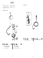
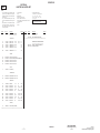
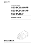
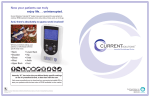
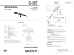
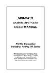
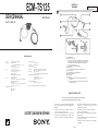
ECM-TS125
SERVICE MANUAL
SECTION 1
GENERAL
This section is extracted
from instruction manual.
AEP Model
Ver 1.0 1999. 05
SPECIFICATIONS
Type
Dimensions
Electret condenser microphone
Microphone parts:
11 × 26 mm (diameter/length)(7/16 × 11/16 in.)
Battery box parts:
40 × 16.5 × 46 mm (w/h/d)
(15/8 × 21/32 × 113/16 in.)
Mass
Microphone parts (including cord):
Approx. 15 g (0.53 oz.)
Battery box parts
(including lithium battery and cord):
Approx. 17 g (0.6 oz.)
Cord
Microphone parts:
∅2.2 mm (3/32 in.)OFC litz cord (2 core shielded)
Length: approx. 1 m (393/8 in.)
Battery box parts:
∅2.2 mm (3/32 in.)OFC litz cord (2 core shielded)
Length: approx. 0.3 m (117/8 in.)
Supplied accessories
Battery box (1)
Holder clip (1)
1
2
Frequently response
100 – 16,000 Hz
Directivity
Unidirectional × 2
Output impedance
3 kΩ ±30%
Sensitivity
Open circuit output voltage level -42 ±4dB
0 dB=1V/Pa, 1,000 Hz(1Pa=10µ bar=94 dB SPL)
Battery life
Approx. 100 hours
(with Sony lithium battery CR2025(not supplied))
Maximum sound pressure input level
Approx. 110 dBSPL
1% wave distortion at 1,000 Hz
(0 dBSPL=2 × 10⁻⁵Pa)
Operating temperature range
0°C – 40°C (32°F – 104°F)
3
4
5
6
7
8
9
POWER switch
Battery check indicator
When you turn the power on, the battery check indicator lights up
momentarily. This is normal. The light tells you that the battery still
has life. When the battery becomes weak, the indicator lights
dimly or does not light at all.
L-shaped stereo miniplug (gold plated)
Battery box
You can clip the battery box to your tie, lapel or pocket.
Microphone jack
L-shaped stereo miniplug (gold plated)
Battery compartment
Microphone
Holder clip
A Interlock the projection of the holder to the groove on the
microphone.
B This microphone holder allows you to tilt the microphone 45°
backward or forward.
Design and specifications are subject to change without notice.
SAFETY CHECK-OUT
After correcting the original service problem, perform the following
safety checks before releasing the set to the customer.
1.
2.
ELECTRET CONDENSER MICROPHONE
MICROFILM
3.
Check the area of your repair for unsoldered or poorly-soldered
connections. Check the entire board surface for solder splashes
and bridges.
Check the interboard wiring to ensure that no wires are
"pinched" or contact high-wattage resistors.
Look for unauthorized replacement parts, particularly
transistors, that were installed during a previous repair. Point
them out to the customer and recommend their replacement.
4.
Look for parts which, through functioning, show obvious signs
of deterioration. Point them out to the customer and
recommend their replacement.
5. Check the B+ voltage to see it is at the values specified.
6. Flexible Circuit Board Repairing
• Keep the temperature of the soldering iron around 270˚C
during repairing.
• Do not touch the soldering iron on the same conductor of the
circuit board (within 3 times).
• Be careful not to apply force on the conductor when soldering
or unsoldering.
—2—
ECM-TS125
SECTION 2
DIAGRAMS
2-1. SCHEMATIC DIAGRAM
2-2. PRINTED WIRING BOARD
1
3
2
4
5
6
7
MIC UNIT
MIC UNIT
A
(L CH)
UNIT BOARD
UNIT BOARD
(SIDE A)
(SIDE B)
D10
MIC1
(L CH)
B
D20
MIC2
(R CH)
C
L
11
11
R
1-673-682- (11)
2 (R CH)
1-673-682-
(11)
MINI PLUG
(MIC OUT)
J1
MIC IN
D
AMP BOARD (SIDE A)
D3
C24
Q2
R22
R23
AMP BOARD (SIDE B)
C22
R24
R21
E
R11
1.0
Q2
2SC4116YG
MIC AMP
S1
POWER
D1
F
ON
0.5
C12
R14
D2
BATTERY
CHECK
LAMP
LITHIUM
BATTERY
CR-2025
3V
R3
OFF
TOTAL CURRENT
MIC UNIT
CONNECT : 700uA
DISCONNECT : 460uA
R1
C1
C14
C24
1
F
C2
G
2.3
0.5
D7
LITHIUM BATTERY
R24
3K
C22
0.01
F
R23
3K
R21
3.9K
Q1
2SC4116YG
MIC AMP
R22
2.2M
S1
L
R
2.3
1.0
C12
0.01
F
C14
1
F
R14
3K
R12
2.2M
R13
3K
R11
3.9K
2.9
R12
R13
Q1
D6
H
11
1-672-000-
(11)
16
• Semiconductor
(MIC OUT)
MINI
PLUG
Location
Ref. No.
Note on Schematic Diagram:
• All capacitors are in µF unless otherwise noted. pF: µµF
50 WV or less are not indicated except for electrolytics
and tantalums.
• All resistors are in Ω and 1/4 W or less unless otherwise
specified.
•
%
: indicates tolerance.
• C : panel designation.
• U : B+ Line.
• Power voltage is dc 3 V and fed with regulated dc power
supply from battery terminal.
• Voltages and waveforms are dc with respect to ground
under no-signal (detuned) conditions.
• Voltages are taken with a VOM (Input impedance 10 MΩ).
Voltage variations may be noted due to normal production tolerances.
• Signal path.
F : MIC
—3—
Location
D1
D2
D3
D6
D7
D10
D20
F-2
F-3
D-2
H-3
G-3
B-3
B-4
Q1
Q2
E-3
D-3
Note on Printed Wiring Board:
• X : parts extracted from the component side.
®
•
: Through hole.
• b : Pattern of the rear side.
Caution:
Pattern face side:
(Conductor B)
Parts face side:
(Component A)
Parts on the pattern face side seen from
the pattern face are indicated.
Parts on the parts face side seen from
the parts face are indicated.
—4—
11
1-672-000-
(11)
SECTION 3
EXPLODED VIEW
NOTE:
• -XX, -X mean standardized parts, so they may
have some differences from the original one.
• Items marked “*” are not stocked since they
are seldom required for routine service. Some
delay should be anticipated when ordering these
items.
3-2. MAIN SECTION
•
The mechanical parts with no reference number
in the exploded views are not supplied.
Accessories and packing materials is given in
the last of this parts list.
•
3-1. BATTERY BOX SECTION
51
5
54
not supplied
54
4
53
52
6
53
7
2
8
55
9
10
1
11
Ref. No.
#1
Ref. No.
Part No.
Description
1
2
4
5
* 6
1-790-506-21
2-545-592-01
X-2542-165-1
2-545-588-01
A-4542-575-A
CORD,MICROPHONE (2 CORE)
BUSHING
CASE(UPPER) ASSY, BATTERY
KNOB,SWITCH (POWER)
AMP BOARD, COMPLETE
7
2-545-589-01 TERMINAL, PLUS
Remarks
Ref. No.
51
52
53
12
Part No.
Description
8
9
10
11
12
2-545-590-01
2-545-599-01
2-545-586-01
2-545-587-01
2-545-668-01
TERMINAL, MINUS
SHEET, BLIND
CASE(LOWER), BATTERY
HOLDER, BATTERY
LABEL, MODEL NUMBER
#1
7-685-103-19 SCREW +P 2 × 5 TYPE2 NON-SLIT
—5—
Part No.
Description
A-4540-182-A CLIP ASSY, HOLDER
X-2542-079-1 CLIP ASSY
3-704-197-12 SCREW (M1.4 × 2.0), LOCKING
Remarks
Ref. No.
54
55
Remarks
—6—
Part No.
Description
Remarks
3-309-597-31 SCREW (1.4), TAPPING,PRECISION
A-4540-570-A MICROPHONE ASSY, LAVALIER (MIC UNIT)
AMP
NOTE:
• Due to standardization, replacements in the
parts list may be different from the parts
specified in the diagrams or the components
used on the set.
• -XX, -X mean standardized parts, so they
may have some difference from the original
one.
• Items marked “*” are not stocked since they
are seldom required for routine service.
Some delay should be anticipated when
ordering these items.
Ref. No.
*
ECM-TS125
SECTION 4
ELECTRICAL PARTS LEST
•
•
•
CAPACITORS:
uF: µF
RESISTORS
All resistors are in ohms.
METAL: metal-film resistor
METAL OXIDE: Metal Oxide-film resistor
F: nonflammable
COILS
uH: µH
Part No.
Description
A-4542-575-A AMP BOARD, COMPLETE
********************
Remarks
1-119-749-11
1-104-908-11
1-162-974-11
1-164-346-11
1-162-974-11
TANTAL. CHIP
TANTAL. CHIP
CERAMIC CHIP
CERAMIC CHIP
CERAMIC CHIP
C24
1-164-346-11 CERAMIC CHIP
33uF
47uF
0.01uF
1uF
0.01uF
1uF
Part No.
SEMICONDUCTORS
In each case, u: µ, for example:
uA...: µA... , uPA... , µPA... ,
uPB... , µPB... , uPC... , µPC... ,
uPD..., µPD...
When indicating parts by reference number,
please include the board name.
Description
Remarks
MISCELLANEOUS
*************
1
1-790-506-21 CORD, MICROPHONE (2 CORE)
************************************************************
< CAPACITOR >
C1
C2
C12
C14
C22
Ref. No.
•
20%
20%
4V
4V
50V
16V
50V
ACCESSORIES & PACKING MATERIALS
*******************************
3-866-282-11 MANUAL, INSTRUCTION (ENGLISH)
A-4540-182-A CLIP ASSY, HOLDER
16V
< DIODE >
D1
D2
D3
D6
D7
8-719-072-95
8-719-064-07
8-719-056-29
8-719-056-29
8-719-056-29
DIODE 015AZ3.9-X-TPL3
LEDSML-310LTT86 (BATTERY CHECK UNIT)
DIODE 015AZ4.7-TPL3
DIODE 015AZ4.7-TPL3
DIODE 015AZ4.7-TPL3
< JACK >
J1
1-764-624-51 JACK(MIC IN)
< TRANSISTOR >
Q1
Q2
8-729-230-63 TRANSISTOR 2SC4116-YG
8-729-230-63 TRANSISTOR 2SC4116-YG
< RESISTOR >
R1
R3
R11
R12
R13
1-216-833-91
1-216-813-11
1-218-706-11
1-216-861-11
1-218-703-11
RES,CHIP
METAL CHIP
METAL CHIP
METAL CHIP
METAL CHIP
10K
220
3.9K
2.2M
3K
5%
1/16W
5%
1/16W
0.50% 1/16W
5%
1/16W
0.50% 1/16W
R14
R21
R22
R23
R24
1-218-703-11
1-218-706-11
1-216-861-11
1-218-703-11
1-218-703-11
METAL CHIP
METAL CHIP
METAL CHIP
METAL CHIP
METAL CHIP
3K
3.9K
2.2M
3K
3K
0.50% 1/16W
0.50% 1/16W
5%
1/16W
0.50% 1/16W
0.50% 1/16W
< SWITCH >
S1
1-692-397-21 SWITCH, SLIDE (POWER)
************************************************************
Sony Corporation
9-926-940-11
—7—
Personal Audio Company
—8—
99E1639-1
Printed in Japan ©1999.5
Published by General Engineering Dept.