1
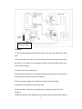
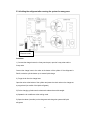
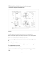
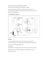
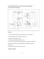
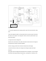
SERVICE MANUAL
AIRCONDITIONER
FLOOR STANDING TYPE
Model:
MFGA-60ARDN1-QC2
CONTENTS
1.
Safety Precautions .............................................................................................................. 1
1.1
Precaution.............................................................................................................................. 1
1.2
Installation.............................................................................................................................. 1
1.3
Caution .................................................................................................................................. 1
1.4
Operational ............................................................................................................................ 2
2.
Dimension ............................................................................................................................ 3
2.1 Indoor Unit .................................................................................................................................. 3
2.2 Outdoor Unit ............................................................................................................................... 4
3.
Refrigerant cycle diagram .................................................................................................. 5
4 . Wiring diagram ........................................................................................................................ 6
5.
.Installation details ................................................................................................................... 7
5.1 Installation place ......................................................................................................................... 7
5.2 Installing ..................................................................................................................................... 8
5.3 Refrigerant pipe connection ..................................................................................................... 10
5.3.3 Installation for the first time ................................................................................................... 15
5.3.4 Adding the refrigerant after running the system for many years ........................................... 20
5.3.5 Re-installation while the indoor unit need to be repaired ...................................................... 22
5.3.6 Re-installation while the outdoor unit need to be repaired.................................................... 25
5.4 Drain Pipe of The Indoor Unit ................................................................................................... 28
5.5 Wiring ....................................................................................................................................... 28
5.6 TEST RUN ................................................................................................................................ 28
6.
.External view and display .................................................................................................... 30
6.1 External view ............................................................................................................................ 30
6.2 CONTROL PANEL ................................................................................................................... 31
7.Operation characteristics ....................................................................................................... 31
8.Electronic function .................................................................................................................. 32
8.1
Main data Introduction ......................................................................................................... 32
8.2
Operation Modes and Functions ......................................................................................... 32
8.3
Other Functions ................................................................................................................... 37
9.Characteristic of temperature sensor ................................................................................... 38
10.Trouble shooting ................................................................................................................... 38
10.1 Protective Function ........................................................................................................... 38
10.2 Self-diagnosis .................................................................................................................... 40
10.3 Troubles and Solutions..................................................................................................... 40
1. Safety Precautions
1.1 Precaution
To prevent injury to the user or other people and property damage, the following instructions must
be followed.
Incorrect operation due to ignoring instruction will cause harm or damage.
Before service unit, be sure to read this service manual at first.
1.2 Installation
For electrical work, contact the dealer, seller, a qualified electrician, or an Authorized service
center.
Do not disassemble or repair the product by yourself.
Sharp edges could cause injury, be especially careful of the case edges and the fins on the
condenser and evaporator.
Be sure the installation area does not deteriorate with age.
Take care to ensure that power cable could not be pulled out or damaged during operation.
Do not place anything on the power cable.
Do not plug or unplug the power supply plug during operation.
Do not store or use flammable gas or combustible near the product.
When flammable gas leaks, turn off the gas and open a window for ventilation before turn the
product on.
If strange sounds, or small or smoke comes from product. Turn the breaker off or disconnect the
power supply cable as soon as possible.
When the product is soaked (flooded or submerged), contact an Authorized service center.
Be caution that water could not enter the product.
Turn the main power off when cleaning or maintaining the product.
When the product is not be used for a long time, disconnect the power supply plug or turn off the
breaker.
1.3 Caution
Always check for gas (refrigerant) leakage after installation or repair of product.
Install the drain hose to ensure that water is drained away properly.
Keep level even when installing the product.
Do not install the product where the noise or hot air from the outdoor unit could damage the
neighborhoods.
Use two or more people to lift and transport the product.
Do not install the product where it will be exposed to sea wind (salt spray) directly.
1
1.4 Operational
Do not expose the skin directly to cool air for long periods of time. (Do not sit in the draft).
Do not use the product for special purposes, such as preserving foods, works of art, etc. It is a
consumer air conditioner, not a precision refrigerant system.
Do not block the inlet or outlet of air flow.
Use a soft cloth to clean. Do not use harsh detergents, solvents, etc.
Do not touch the metal parts of the product when removing the air filter. They are very sharp.
Do not step on pr put anything on the product. (outdoor units)
Always insert the filter securely. Clean the filter every two weeks or more often if necessary.
Do not insert hands or other object through air inlet or outlet while the product is operated.
Do not drink the water drained from the product.
Use a firm stool or ladder when cleaning or maintaining the product.
Replace the all batteries in the remote control with new ones of the same type. Do not mix old and
mew batteries or different types of batteries.
Do not recharge or disassemble the batteries. Do not dispose of batteries in a fire.
If the liquid from the batteries gets onto your skin or clothes, wash it well with clean water. Do not
use the remote of the batteries have leaked.
2
2. Dimension
2.1 Indoor Unit
Dimension
Mode
MFGA-60ARDN1-QC2
W(mm)
D(mm)
H(mm)
610
390
1925
3
2.2 Outdoor Unit
MODEL
A
B
C
D
E
F
H
MOU-60HDN1-R
940
600
376
400
340
360
1245
4
3. Refrigerant cycle diagram
INDOOR
OUTDOOR
Electronic Expansion Valve
LIQUID SIDE
2-WAY VALVE
CAPILIARY TUBE
HEAT
EXCHANGE
(EVAPORATOR)
HEAT
EXCHANGE
(CONDENSER)
GAS SIDE
REVERSING VALVE
3-WAY VALVE
ACCUMULATOR
COOLING
COMPRESSOR
5
HEATING
4 . Wiring diagram
MFGA-60ARDN1-QC2
Indoor Unit
Outdoor Unit
6
5.
.Installation details
5.1 Installation place
5.1.1 Indoor Unit
a. A place which provides the spaces around the indoor unit as required above in the
diagram.
b. A place where is no obstacle near the inlet and outlet area.
c. A place which can bear the weight of the indoor unit.
d. A place which allows the air filter to be removed downward.
e. A place where the reception range is not exposed to direct sunlight.
f. In the center of the room where possible.
5.1.1.1
Please stand the unit in hard and flat ground;
Please reserve space for installation and maintenance.
5.1.1.2
Please check the elevation difference between the indoor unit and the outdoor unit, the length of
the refrigerant pipe, and the curved places (bend) of the pipe are no more than the following numbers:
Elevation difference: no more than 10M (if the elevation difference between indoor and outdoor unit
is more than 10 meters, it is recommended that the indoor unit be located higher than the outdoor unit.)
Pipe length: no more than 20M.
Bends: no more than 3 places.
5.1.2
Outdoor Unit
5.1.2.1 Before installing the outdoor unit, you should:
a). Select a place where no direct sunlight or other heat-radioactivity may reach. A sunshade is needed if
it is unavoidable.
b). Select a place that is easy to connect indoor unit's pipe and electric wires.
c). Avoid a place where combustible gas may leak or stay.
d). Keep it in mind that water may drain out of the outdoor unit while in "Heat" mode.
Caution:
Installation in the following places may cause trouble. If it is unavoidable to use in such places, please
consult with the dealer.
7
a. A place full of machine oil.
b. A saline place such as coast.
c. Hot-spring resort.
d. A place full of sulfide gas.
e. A place where there are high frequency machines such as wireless installation, welding
machine, medical facility.
f. A place of special environmental conditions.
5.1.2.2 If the outdoor unit is to be installed on a roof or where no constructions are around, you should
avoid
hard
wind blows
directly
to
the air
outlet,
because
it may cause
trouble
for
air-flow shortage.
5.1.2.3 Reserve enough space for installation, maintenance and unit-functioning.
Remove as many obstacles as possible nearby.
5.2 Installing
5.2.1 Indoor Unit:
1. Anti-falling;
To prevent the indoor unit from falling, you must:
a. Pay full attention to the unit because its long outer shape makes it easy to fall;
b. Firmly fix the unit to the wall or in the ground to avoid accidental falling.
8
2. Dismounting the air-inlet grid
Please take off the air-inlet grid before connecting the pipes/wires.
Pull down the two knobs on the grid, take off the two screws, then the air-inlet grid goes
free.
3. Take the Pipe Clip off before connecting the pipes and wiring; fit it when these finished.
Use accessories to connect the pipes/wires on both sides and back side.
9
5.2.2 Outdoor Unit:
1. Ship the a/c to the installation place originally packed;
2. Be careful while hanging the unit because the center of gravity of the unit is not
centralized;
3. Do not make the angle of inclination more than 45 degrees while shipping;(Avoid
horizontal storage)
4. Be sure the electric insulation work is well done if installed on metal ceiling / wall.
5. Fix the unit feet with bolts (M10/M8). Be sure the unit is fixed strongly enough to
against blast or earthquake.
6. Make a concrete basement to the unit by the following references.
For the value of A and B, please refer to the dimension table.
5.3 Refrigerant pipe connection
5.3.1
Pipe length and the elevation
The correct refrigerant quantity filled in the 5-meter-long pipe of the outdoor unit is marked
on the Product Data Plate. If you have to use longer pipe for every meter plus pipe, the
refrigerant should be added according to the following calculation.
10
Pipe size
Standard
Max.
Max.
Additional
length
Elevation
Length
refrigerant
(m)
B (m)
A (m)
(g/m)
5
15
30
40
Capacity
Btu/h
Gas
Liquid
5/8’’
3/8’’
(Ф16.0)
(Ф9.52)
MFGA-60ARDN1-QC2
Caution:
Capacity is base on standard length and maximum allowance length is base of reliability.
Oil trap should be installed per 5-7 meters.
5.3.2
Piping connection
5.3.2.1 Connecting Of Refrigerant Pipe
a) Only the correctly installing of indoor and outdoor unit done, can the refrigerant pipe
be connected.
b) The cut-off valves are completely close before ex-work. Before connecting the
refrigerant pipe, be careful to check whether the valves are completely close.
c) The connecting procedure of refrigerant pipe: first, unscrew the two valves on the
outdoor unit and the pipe-jointing nut on the indoor unit(please keep them care fully).
Please connect the refrigerant pipe according to the manual, the pipe-jointing nut should
be screw tightly and no leakage. Note: you need two wrenches to make balance.
d)
When the connecting of refrigerant pipe is finished, before power on the system, you
11
should vacuum the indoor unit through the maintenance port on the cut-off valves, or open
the high-pressure valve, and exhaust the air through the maintenance port on the
low-pressure valve(closed). It will take about ten seconds. Then screw tightly the
maintenance port. (When supplement the refrigerant, fill through the maintenance port
of the low-pressure valves on the outdoor unit ).
e) Open all the valves completely before power on the system, or it will be sick for low
efficiency.
f)
Gas leak check. Make sure no gas from connections with leak detector or soap water.
Caution:
A: Lo packed valve B: Hi packed valve
C and D are ends of indoor unit connection.
Caution in Handling the Packed Valve
a. Open the valve stem until it hits against the stopper. Do not try to open it further.
b. Securely tighten the valve stem cap with a spanner or the link.
Notes for the bendable pipe
a. The bendable pipe should be used on the indoor side;
b. Bend angel may not exceed 90 degrees;
c. The bend location should be made on the center of the pipe if possible, as for bend
radius, the bigger the better;
12
d. The bendable pipe may not be bent for more than 3 times.
Bend the thin pipe
a. While bending, expose the pipe by cutting the concave gap on the bending
heat-insulation pipe(roll it with soft band after bent).
b. To avoid pipe deformation, the radius is the bigger the better.
c. Use a pipe-bending device to make the compact bending pipe.
5.3.2.2 Using bronze pipe selling in market
Completely shut the cut-off valves of the outdoor unit (as ex-work status). After the
refrigerant pipe has been connected with both the indoor and outdoor unit, let the air
exhaust out from the maintenance gap on he low-pressure cut-off valves of the
outdoor unit. Screw the nuts tightly on the maintenance gap after the air has been
drained.
5.3.2.3 To make the refrigerant pipe unblocked completely
You should keep the cut-off valves of the outdoor unit completely open after you have
finished the above steps (5.3.2.1 or 5.3.2.2)
Note:
1.Before screwing the reamer nut, smear the pipe and the connecting surface with
refrigerant oil;
2.Check and make sure there is no leakage by soap-water or leakage-checker after
connecting;
3.Be sure the connecting joint on the indoor side is insulated.
4.Use two wrenches to connecting the pipes.
13
Additional
Outside diameter
Torque
tightening
torque
mm
inch
N.cm
N.cm
Ф9.52
3/8
2500
2600
Ф12.7
1/2
3500
3600
Ф16
5/8
4500
4700
Ф19
3/4
6500
6700
14
5.3.3 Installation for the first time
Air and moisture in the refrigerant system have undesirable effects as below:
●
●
●
●
●
Pressure in the system rises.
Operating current rises.
Cooling or heating efficiency drops.
Moisture in the refrigerant circuit may freeze and block capillary tubing.
Water may lead to corrosion of parts in the refrigerant system.
Therefore, the indoor units and the pipes between indoor and outdoor units must be
leak tested and evacuated to remove gas and moisture from the system.
Gas leak check (Soap water method):
Apply soap water or a liquid neutral detergent on the indoor unit connections or
outdoor unit connections by a soft brush to check for leakage of the connecting points of
the piping. If bubbles come out, the pipes have leakage.
1. Air purging with vacuum pump
(Indoor unit)
(Outdoor unit)
(Liquid side)
Two-way valve
Close
(Gas side)
Three-way valve
Manifold valve
Compound meter
Pressure
gauge
20Pa
Lo
Handle Lo
Charge hose
Close
Hi
Handle Hi
Charge hose
Vacuum
pump
Vacuum
pump
1) Completely tighten the flare nuts of the indoor and outdoor units, confirm that both the
15
2-way and 3-way valves are set to the closed position
2) Connect the charge hose with the push pin of handle lo to the 3-way valves gas
service port..
3) Connect the charge hose of handle hi connection to the vacuum pump.
4) Fully open the handle Lo of the manifold valve.
5) Operate the vacuum pump to evacuate.
6) Make evacuation for 30 minutes and check whether the compound meter indicates -0.1Mpa.
If the meter does not indicate -0.1Mpa after pumping 30 minutes, it should be pumped 20
minutes more. If the pressure can’t achieve -0.1Mpa after pumping 50 minutes, please check if
there are some leakage points.
Fully close the handle Lo valve of the manifold valve and stop the operation of the vacuum
pump. Confirm that the gauge needle does not move (approximately 5 minutes after
turning off the vacuum pump).
7) Turn the flare nut of the 3-way valves about 45° counterclockwise for 6 or 7seconds
after the gas
coming out, then tighten the flare nut again. Make sure the pressure display in the
pressure indicator is a little higher than the atmosphere pressure. Then remove the
charge hose from the 3 way valve.
8) Fully open the 2 way valve and 3 way valve and securely tighten the cap of the 3 way
valve.
2. Air purging by refrigerant
16
Procedure:
1). Confirm that both the 2-way and 3-way valves are set to the closed position.
2). Connect the charge set and a charging cylinder to the service port of the 3-way valve.
3). Air purging
Open the valves on the charging cylinder and the charge set. Purge the air by loosening
the flare nut on the 2-way valve approximately 45’ for 3 seconds then closing it for 1
minute; repeat 3 times.
After purging the air, use a torque wrench to tighten the flare nut on the 2-way valve.
4). Check the gas leakage
Check the flare connections for gas leakage.
5). Discharge the refrigerant
Close the valve on the charging cylinder and discharge the refrigerant by loosening the
flare nut on the 2-way valve approximately 45’ until the gauge indicates 0.3 to 0.5 Mpa.
6). Disconnect the charge set and the charging cylinder, and set the 2-way and 3-way
valves to the open position.
Be sure to use a hexagonal wrench to operate the valve stems.
7). Mount the valve stems nuts and the service port cap.
Be sure to use a torque wrench to tighten the service port cap to a torque 18N·m.
Be sure to check the gas leakage.
3. Adding the refrigerant if the pipe length >5m
17
Electronic scale
Procedure:
1). Connect the charge hose to the charging cylinder, open the 2-way valve and the 3-way
valve.
Connect the charge hose which you disconnected from the vacuum pump to the valve at
the bottom of the cylinder. If the refrigerant is R410A, make the cylinder bottom up to
ensure the liquid charge.
2). Purge the air from the charge hose
Open the valve at the bottom of the cylinder and press the check valve on the charge set
to purge the air (be careful of the liquid refrigerant).
3) Put the charging cylinder onto the electronic scale and record the weight.
4) Operate the air conditioner at the cooling mode.
5) Open the valves (Low side) on the charge set and charge the system with liquid
refrigerant.
6).When the electronic scale displays the proper weight (refer to the table), disconnect the
18
charge hose from the 3-way valve’s service port immediately and turn off the air
conditioner before disconnecting the hose.
7). Mount the valve stem caps and the service port
Use torque wrench to tighten the service port cap to a torque of 18N.m.
Be sure to check for gas leakage.
19
5.3.4 Adding the refrigerant after running the system for many years
Electronic scale
Procedure:
1). Connect the charge hose to the 3-way service port, open the 2-way valve and the
3-way valve.
Connect the charge hose to the valve at the bottom of the cylinder. If the refrigerant is
R410A, make the cylinder bottom up to ensure liquid charge.
2). Purge the air from the charge hose
Open the valve at the bottom of the cylinder and press the check valve on the charge set
to purge the air (be careful of the liquid refrigerant).
3) Put the charging cylinder onto the electronic scale and record the weight.
4) Operate the air conditioner at the cooling mode.
5) Open the valves (Low side) on the charge set and charge the system with liquid
refrigerant.
20
6).When the electronic scale displays the proper weight (refer to the gauge and the
pressure of the low side), disconnect the charge hose from the 3-way valve’s service port
immediately and turn off the air conditioner before disconnecting the hose.
7). Mount the valve stem caps and the service port
Use torque wrench to tighten the service port cap to a torque of 18N.m.
Be sure to check for gas leakage.
21
5.3.5 Re-installation while the indoor unit need to be repaired
1. Collecting the refrigerant into the outdoor unit
Procedure
1). Confirm that both the 2-way and 3-way valves are set to the opened position.
Remove the valve stem caps and confirm that the valve stems are in the opened position.
Be sure to use a hexagonal wrench to operate the valve stems.
2). Connect the charge hose with the push pin of handle lo to the 3-way valves gas service
port.
3). Air purging of the charge hose
Open the handle Lo valve of the manifold valve slightly to purge air from the charge hose
for 5 seconds and then close it quickly.
4). Set the 2-way valve to the close position.
5). Operate the air conditioner at the cooling cycle and stop it when the gauge indicates
0.1MPa.
22
6). Set the 3-way valve to the closed position immediately
Do this quickly so that the gauge ends up indicating 0.3 to 0.5Mpa.
Disconnect the charge set, and tighten the 2-way and 3-way valve’s stem nuts.
Use a torque wrench to tighten the 3-way valves service port cap to a torque of 1.8 kgf.m.
Be sure to check for gas leakage.
2. Air purging by the refrigerant
Procedure:
1). Confirm that both the 2-way and 3-way valves are set to the closed position.
2). Connect the charge set and a charging cylinder to the service port of the 3-way valve.
Leave the valve on the charging cylinder closed.
3). Air purging
Open the valves on the charging cylinder and the charge set. Purge the air by loosening
the flare nut on the 2-way valve approximately 45’ for 3 seconds then closing it for 1
minute; repeat 3 times.
23
After purging the air, use a torque wrench to tighten the flare nut on the 2-way valve.
4). Check the gas leakage
Check the flare connections for gas leakage.
5). Discharge the refrigerant
Close the valve on the charging cylinder and discharge the refrigerant by loosening the
flare nut on the 2-way valve approximately 45’ until the gauge indicates 0.3 to 0.5 Mpa.
6). Disconnect the charge set and the charging cylinder, and set the 2-way and 3-way
valves to the open position.
Be sure to use a hexagonal wrench to operate the valve stems.
7). Mount the valve stems nuts and the service port cap.
Be sure to use a torque wrench to tighten the service port cap to a torque 18N.m.
Be sure to check the gas leakage.
24
5.3.6 Re-installation while the outdoor unit need to be repaired
1. Evacuation for the whole system
Procedure:
1). Confirm that both the 2-way and 3-way valves are set to the opened position.
2). Connect the vacuum pump to 3-way valve’s service port.
3). Evacuation for approximately one hour
Confirm that the compound meter indicates -0.1Mpa.
4). Close the valve (Low side) on the charge set, turn off the vacuum pump, and confirm
that the gauge needle does not move (approximately 5 minutes after turning off the
vacuum pump).
5). Disconnect the charge hose from the vacuum pump.
2. Refrigerant charging
25
Electronic scale
Procedure:
1). Connect the charge hose to the charging cylinder, open the 2-way valve and the 3-way
valve.
Connect the charge hose which you disconnected from the vacuum pump to the valve at
the bottom of the cylinder. If the refrigerant is R410A, make the cylinder bottom up to
ensure liquid charge.
2). Purge the air from the charge hose
Open the valve at the bottom of the cylinder and press the check valve on the charge set
to purge the air (be careful of the liquid refrigerant).
3) Put the charging cylinder onto the electronic scale and record the weight.
4). Open the valves (Low side) on the charge set and charge the system with liquid
refrigerant.
If the system cannot be charge with the specified amount of refrigerant, or can be charged
with a little at a time (approximately 150g each time) , operating the air conditioner in the
26
cooling cycle; however, one time is not sufficient, wait approximately 1 minute and then
repeat the procedure.
5).When the electronic scale displays the proper weight, disconnect the charge hose from
the 3-way valve’s service port immediately.
If the system has been charged with liquid refrigerant while operating the air conditioner,
turn off the air conditioner before disconnecting the hose.
6). Mounted the valve stem caps and the service port
Use torque wrench to tighten the service port cap to a torque of 18N.m.
Be sure to check for gas leakage.
27
5.4 Drain Pipe of The Indoor Unit
1. Make sure the drain pipe is connected to the outdoor side downward;
2.The hard polyvinyl chloride(PVC)plastic pipe (external diameter 26 mm) sold is the
market is suitable for the attached soft drain pipe;
3.Please connect the Soft Drain Pipe with the Drain Pipe, then fix it with band;
4.If you have to connect the Drain Pipe indoors, to avoid condensing caused by air intake,
you must cover the pipe with heat-insulation material (polyethylene with Specific Gravity of
0.03, at least 9 mm in thickness), and use Glue Band to fix it.
5.After the Drain Pipe has been connected, please check if the water drains out of the
pipe efficiently and has no leakage.
6.Refrigerant pipe and Drainpipe should be heat-insulated to avoid condensing and
water-dropping later on.
5.5 Wiring
Please refer to the Wiring Diagram.
Note: The power supply of the air conditioner is different according to the models. Please
refer to the WIRING DIAGRAM pasted on the indoor and outdoor units before wire
connection.
5.6 TEST RUN
Perform test operation after completing gas leak and electrical safety check. The test
operation time should last more than 30 minutes.
1. Open the panel and lift the panel up to angle which remains fixed. Do not lift the panel
28
any further when it stops with a "click" sound.
2. Press the manual switch button twice until the operation indicator lights, the unit will
operate on Manual Cool mode.
3. Check if all the functions works well while testing the air conditioner. Especially check
whether the drainage of indoor unit is smooth or not.
4. Press the manual switch button again till the operation indicator turns dark after
finishing the test operation and the unit stops operation.
29
6.
.External view and display
6.1 External view
This unit consists of indoor unit and outdoor unit.
Note:
All the pictures in this manual are for explanation purpose only.
They may be slightly different from the air conditioner you purchased (depend on model).
The actual shape shall prevail.
30
6.2 CONTROL PANEL
Control Buttons and Functions
7.Operation characteristics
CAUTION:
1. If air conditioner is used outside of the above conditions, certain safety protection
features may come into operation and cause the unit to function abnormally.
2. Room relative humidity less than 80%. If the air conditioner operates in excess of
31
this figure, the surface of the air conditioner may attract condensation. Please sets the
vertical air flow louver to its maximum angle (vertically to the floor), and set HIGH fan
mode.
3. Optimum performance will be achieved within this operating temperature.
8.Electronic function
8.1 Main data Introduction
Ts : Set temperature,
T1 : Room temperature
T2: Evaporator coil temperature
T3: Condenser coil temperature
T4: Outdoor ambient temperature
8.2 Operation Modes and Functions
8.2.1Manual Operation
8.2.2 Heating Mode
8.2.2.1 Four-way valve opens at once , while defrosting process closes.
8.2.2.2
After AC starts up, the PCB will calculate the capacity demand.
a
b
c
d
3
2
1
0
ΔT=3
Capacity demand=(a/b/c/d)×HP×△1×△2
△1 is the factor depending on the outdoor ambient temp.
△2 is the factor depending on the evaporator coil temp.
32
According to the capacity demand, the compressor will run at the corresponding frequency.
8.2.2.3 Indoor Fan Action
Anytime remote switchover for fan speed among high/low/auto, anti-cold air function takes
priority.
Auto fan in heating mode
8.2.2.4 Outdoor fan
In low temp. cooling zone, the outdoor fan will be controlled as below:
8.2.2.5 Anti-cold air:
When evaporator coil temp.T2 is getting higher,
T2>TE2, the indoor fan will run at setting speed.
TE1<T2<TE2, the indoor fan will run at low speed.
33
When T2 is getting lower,
TE4<T2<TE3,the indoor fan will run at low speed.
T2<TE4, the indoor fan will shut off.
T2
Setting
TE2
TE1
TE3
Low
TE4
Off
While TE1=30, TE2=35, TE3=32, TE4=26
8.2.3 Defrost (only available to heating mode)
8.2.3.1 Condition of defrosting:
The units run with T3<-2℃ for 40 minutes
8.2.3.2 Defrosting Action:
34
8.2.3.3 Ending Of Defrosting Condition (Only if one of the following items is satisfied):
(1) Time of defrosting lasts 10 minutes.
(2) Temperature of outdoor coil T3 is up to 15°C.
(3) AC has changed to other modes or shut off.
8.2.3.4 PTC function
(1) Open conditions: (If all the following conditions are satisfied, the PTC will open)
¬ Indoor fan is on
¬ Compressor is on
¬ Indoor evaporator temperature T2 ≤40
¬ T1-3≤ TS-6 ℃
(2). Close conditions: (If one of the following conditions is satisfied, the PTC will close)
¬ T1-3>TS
¬ No capacity requirement
¬ compressor is off
¬ Indoor fan is off
¬ Indoor evaporator temperature T2 > 52
If the PTC opens, the indoor fan will be closed 15sec delay.
8.2.4 Cooling Mode
8.2.4.1
Four-way valve is closed.
If four-way valve is open before the machine enters cooling mode, then four-way valve will
35
be closed at the first time, the compressor starts under the cooling mode.
8.2.4.2
Conditions for the compressor and outdoor fan action (Ts = set temperature)
a
b
c
d
3
2
2
0
Capacity demand=(a/b/c/d)×HP×△1×△2
△1 is the factor depending on the outdoor ambient temp.
△2 is the factor depending on the evaporator coil outlet temp.
According to the capacity demand, the compressor will run at the corresponding frequency.
8.2.4.3
Action of Indoor Fan
HIGH/ LOW/AUTO fan can be switched over by your comfort.
Auto fan under cooling mode.
8.2.4.4
Outdoor Fan
8.2.5 Dehumidifying Mode
8.2.5.1 Indoor fan speed is low.
8.2.5.2 Four-way valve is closed,. the compressor and outdoor fan will operate the same as in cooling
mode.
8.2.6 Auto Mode
When entering auto mode, the heating, fan only or cooling operation will be automatically chosen
36
according to the room temperature T1 and the set temperature Ts.
Condition
Mode
T1-Ts≥2°C
Cooling
-1°C≤ T1-Ts<2°C
Fan
T1-Ts<-1°C
Heating
8.2.7 Fan Only Mode
8.2.7.1 Temperature setting function is disabled, and no setting temperature is displayed.
8.2.7.2 Under this mode, four-way valve, compressor and outdoor fan are shut down.
8.2.7.3 High/Low/Auto fan can be switched over through manual control. Auto fan will be controlled in line
with cooling auto fan with temperature set to be 24°C.
8.3 Other Functions
8.3.1 LCD display
Mode, Set temp. ,fan speed, time, timer, protection etc.
8.3.2 Timer
The machine should be provided with max. Interval of 24h and min. resolution ratio of 30
minutes.
37
9.Characteristic of temperature sensor
Temp.℃ Resistance KΩ Temp.℃ Resistance KΩ Temp.℃ Resistance KΩ
-10
62.2756
17
14.6181
44
4.3874
-9
58.7079
18
13.918
45
4.2126
-8
56.3694
19
13.2631
46
4.0459
-7
52.2438
20
12.6431
47
3.8867
-6
49.3161
21
12.0561
48
3.7348
-5
46.5725
22
11.5
49
3.5896
-4
44
23
10.9731
50
3.451
-3
41.5878
24
10.4736
51
3.3185
-2
39.8239
25
10
52
3.1918
-1
37.1988
26
9.5507
53
3.0707
0
35.2024
27
9.1245
54
2.959
1
33.3269
28
8.7198
55
2.8442
2
31.5635
29
8.3357
56
2.7382
3
29.9058
30
7.9708
57
2.6368
4
28.3459
31
7.6241
58
2.5397
5
26.8778
32
7.2946
59
2.4468
6
25.4954
33
6.9814
60
2.3577
7
24.1932
34
6.6835
61
2.2725
8
22.5662
35
6.4002
62
2.1907
9
21.8094
36
6.1306
63
2.1124
10
20.7184
37
5.8736
64
2.0373
11
19.6891
38
5.6296
65
1.9653
12
18.7177
39
5.3969
66
1.8963
13
17.8005
40
5.1752
67
1.83
14
16.9341
41
4.9639
68
1.7665
15
16.1156
42
4.7625
69
1.7055
16
15.3418
43
4.5705
70
1.6469
10.Trouble shooting
10.1
Protective Function
10.1.1 3-minute delay for the compressor start-up
10.1.2 Evaporator protection against high temperature
10.1.2.1
Only available under heating mode.
10.1.2.2
The operation principle is as follows: (T2 = evaporator temperature)
Condition
Outdoor fan
Compressor
Evaporator temp.≥60°C(last 3 seconds) Off
Off
Evaporator temp.<54°C
On
On
10.1.3 Evaporator Protection against low temperature
10.1.3.1
Only available under cooling and dehumidifying status.
10.1.3.2
Protection principle:
38
10.1.3.3
Condition
Outdoor fan
Compressor
T2≤2°C(last 3 minutes)
Off
Off
T2≥7°C
On
On
The restart of the compressor shall execute the delay protection.
10.1.4 Condenser high temperature protection
10.1.4.1
Only available to cooling and dehumidifying mode.
10.1.4.2
Action condition
Condition
10.1.4.3
Outdoor fan
Compressor
Condenser temp.≥65°C(last 3 seconds) Off
Off
Condenser temp.<52°C
On
On
Delay protection should be performed when the compressor restarts.
10.1.5 Outdoor protection
When outdoor protection signal is high level(last 4 seconds), outdoor unit will perform
protection: the whole machine will be shut down while the indoor unit will indicate the
corresponding protection signal(Ed).
The A/C will recover if outdoor errors are eliminated after the outdoor protection occurs.
39
10.2
Self-diagnosis
Contents
Codes
P0
10.3
Evaporator low temp. protection
P1
Defrosting or anti-cold air
Ed
Outdoor unit protection /outdoor temp. sensor is circuit or
short circuit
E1
Communication protection between indoor and outdoor
units
E2
Temp. sensor T1 is open circuit or short circuit
E3
Temp. sensor T2 is open circuit or short circuit
E4
Temp. sensor T2B is open circuit or short circuit
E7
EEPROM chip malfunction
Troubles and Solutions
Before calling for service, please review the following list of common problems and
solutions.
Problem
Possible Cause
Solutions
Air conditioner
does not
operate at all
Power failure
Wait for power restoring
The power supply is disconnected.
Switch on the main power
switch
The power fuse is blown.
Change the fuse
Air conditioner
does not
cool or
heat well
Air conditioner
does not
cool or
heat at all
The timer is set.
Wait or cancel timer setting
The batteries of the remote control
are exhausted
Change the batteries.
The temperature setting is too high
or too low.
Set a more comfortable
temperature.
The air filter is clogged with dust
Clean the filter
The air inlet or outlet of the outdoor
unit is blocked
Clear up the block
Doors or windows are open
Close the doors or windows
The air inlet or outlet of the outdoor
unit is blocked
Clear up the block first, then
begin to operate.
Three-minute protection feature
Wait for a while
The temperature setting is not
appropriated
Set the temperature
properly
40
If you still cannot solve the problem after trying the above, pull out the power plug and call
the dealer.
The following displays indicate an error or problem(24K):
Number
1
2
3
4
5
Display code
Problems
What to do
Temperature Sensor is
off or short-circuit.
Contact service people
Outdoor unit protection
/outdoor temp. sensor is
circuit or short circuit
Contact service people
The temperature of the
evaporator of indoor unit
is too low (For the
protection feature, the
compressor turns off
automatically)
The temperature of the
evaporator of indoor unit is
too low (For the protection
feature, the compressor
turns off automatically)
EEPROM chip
malfunction
Contact service people
Defrosting or anti-cold air
The unit will auto restart
after finishing the
defrosting or the
temperature of the Heat
Exchanger of indoor unit
raise.
E1 E2 E3 E4
Ed
P0
E7
P1
CAUTION:
When the power cord is to be replaced, replacement work shall be performed by
authorized personnel only.
41