1
ISP Stitching & Bindery Products
OWNERS
MANUAL
M2000
ISP Stitching & Bindery Products
Includes Parts for
CTTT2606R3
NOTES
Section
1
INTRODUCTION
Here are the instructions on
how to install
operate, maintain, and make
repairs on your...
M2000 STITCHER HEAD
Stitcher Head Serial Number____________________
Stitcher Head Wire Size____________________
Stitcher Head Part Number______________________
Stitcher Head Crown Width ____________________
When ordering parts or requesting information, please state: Quantity required, part number, part name,
model, wire size, crown width, stitcher head part number, and stitcher head serial number.
The M2000 Stitching Head has been engineered and developed to provide you with the finest equipment
available for your stitching needs. With proper care and maintenance it will give you years of satisfactory
efficient service. This manual shows you how to get top performance from your stitcher and is divided into
6 major sections.
Read the M2000 Manual thoroughly. Study it carefully. Best stitching performance will be assured, if all
the adjustments are made as instructed.
1
PRODUCT SPECIFICATIONS
Unit Weight:
Lbs.
4.5 lbs.
Unit Envelope Size:
M2000 Head Without Wire Guide:
Notes
2
Height
Length
Width
11 in.
3.12 in.
1.82 in.
Section
2
SAFETY PRECAUTIONS
AND PROCEDURES
SAFETY
1.
Make sure electrical power is turned off before
performing any adjustment or maintenance.
2.
Keep hand, tools, hair, and clothing clear of
stitching area.
DANGER
3.
Become familiar with the moving components
of your machine. Keep fingers away from areas
that could pinch or cut.
KEEP HANDS CLEAR OF
STITCHING AREA
4.
Wear adequate safety equipment for eye and
face protection. Observe your plant safety
rules.
5.
Practice “good housekeeping” in your work
area. Keep it as clean and uncluttered as
possible.
6.
A well maintained machine is a safer machine.
Clean and lubricate the machine at regular
intervals. Check machine daily for broken or
worn parts. Replace as necessary. DO NOT
attempt to operate the machine if a part is
broken.
7.
Route all electrical cables away from pedestrian
transportation lanes.
8.
Make sure adequate safety guards and covers
are in place. If you are unsure how to safely
operate or maintain your Stitcher, contact your
Service Representative.
CAUTION
FOR YOUR SAFETY, MAKE
SURE ALL COVERS ARE
PROPERLY IN PLACE BEFORE
OPERATING MACHINE
3
Section
3
ASSEMBLY,LUBRICATION,
INSTALLATION
C
B
Note:
D
C
E
A (From wire coil)
These instructions must be followed to insure proper
installation, efficient operation and the prevention
of serious damage to your stitcher.
Before Unpacking:
Examine the outside of the crate or carton for any
visible damage. If damaged DO NOT UNPACK
THE STITCHER. Notify the carrier who delivered the stitcher.
F
After Unpacking:
H
Examine your stitcher carefully for any damage in
transit. If damaged, DO NOT INSTALL THE
STITCHER. Notify your nearest representative and
the carrier who delivered your stitcher.
G
J
L
I
Make certain that you get a signed copy of the
Carrier Inspector’s Report of the damage incurred.
K
ASSEMBLY
1.
Clamp or bolt the M2000 head to your machine
2.
Install Wire Guide Spring into wire guide
bracket of M2000 Head.
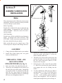
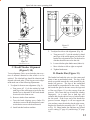
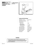
THREADING WIRE AND
ADJUSTING WIRE
STRAIGHTENERS (See fig. 1)
1.
Draw wire (Index A) by hand, from the coil.
2.
Thread the wire through the slot (Index B) at
the end of the wire guide spring, , through the
wire guides (Index C), between the thin and
thick felt wire wipes (Index D), through the
upper wire straightener (Index E), and through
the lower wire straightener (Index F).
4
Figure 1
(CTTT2605 Scene 3, Scene 4)
3.
Release the rotator operating spring (Index H)
from the rotator and swing it to the left.
Remove Rotator (Index K).
4.
Thread the wire between the tension pawl and
tension roll (Index G). Feed the wire through
the wire cutter lead-in hole (Index I) in the
bottom of the face plate.
5.
Push grip post to left to open the grip (Index
J). Insert wire and release the post so that the
grip engages the wire for feeding into the
rotator.
6.
To check adjustment, hold open grip (Index J
and pull about 1 1\2 feet of wire from below
face plate. Cycle machine once by hand to
cut wire. Cycle machine again by hand to
observe wire straightness. The wire (Index L)
should point straight down, prior to being cut.
7.
8.
Adjust the upper wire straightener, beginning
at position shown, (Index E) so that the wire
points straight down. Adjust the lower wire
straightener, beginning at the 3:00 o'clock
position, (Index F) so that the wire (Index L)
feeds straight down.
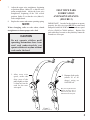
FELT WIPE PADS
LUBRICATION
AND MAINTAINANCE:
(FIGURE 2)
Replace the rotator and rotator operating spring.
NOTE:
When changing coils or wire sizes, check
straighteners to insure proper wire feed.
CAUTION
IMPORTANT! In order for the stitchers to operate
properly, the felt wire wipes MUST be rotated and
dampened with SAE 20W oil before each new spool
of wire (50,000 to 70,000 stitches). Replace felt
pads when they become so dirty that they cannot be
rotated to a clean spot.
Do not operate stitcher until
operating instructions have been
read and understood-do not
operate stitcher at anytime without
work under the head.
1. After every wire
spool, rotate the
dirty area of the
pads slightly so that
a clean area can be
used for the next
wire spool.
Ro
tat
2. Dampen both pads
(about 30 to 40
drops) using an
SAE 20W oil.
e
Dirty area of pads has been
slightly rotated so that a
clean area of pads can be
used for the next wire spool.
Figure 2
(CTTT2605 Scene 7)
5
A
F
G
B
E
H
Figure 3
(CTTT2605 Scene 5)
D
Figure 4
C
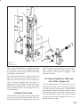
STITCHING HEAD
LUBRICATION:
(FIGURES 3 & 4)
Typically, the 1/2 inch crown stitcher will run for
1,000,000 cycles without additional lubrication.
However, the following procedure used after each
spool of wire will assure optimum life and
performance. Use ISP lubricant #CA9640.
A. Inject lube into hole, or remove and lube shafts.
B. Wipe area clean and inject a small amount of
lube into cam area.
(CTTT2605 Scene 6)
E.
Wipe clean inside of rotator holder.
F.
Inject a small amount of lube into cam area of
driver bar.
G. Inject lube into cutter operating slide.
H. Wipe driver clean, and apply a light coating of
lube.
After prolonged use (or storage) accumulations of
wire dust, dirt, or other contaminants can mix with
the stitcher lubricant. This will reduce the lubricant's
effectiveness. The following procedure is
recommended every 1,000,000 cycles.
1.
Disassemble the head and clean all parts.
C. Remove rotator, wipe rotator clean and lube
rotator body.
2.
Lightly lube all sliding surfaces using ISP
lubricant #CA9640.
D. Apply lube to rotator ramp.
3.
Double check lube points A through H.
6
Section
4
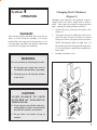
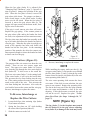
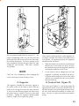
Changing Work Thickness:
(Figure 5)
OPERATION
Changing work thickness will probably require a
change of the wire draw length used to make a
stitch. This is done by raising or lowering the face
plate. Change face plate position as follows:
General:
After having properly installed and set up the machine, it is now ready for stitching. It is recommended that each operator be instructed as to correct operating procedure and normal adjustments
necessary for varying work conditions.
1.
Switch off power, loosen the face plate screw
(Index A).
2.
Turn grip release lever (Index B) clockwise to
raise face plate for more wire draw or counter
clockwise to lower face plate for less wire draw.
NOTE: Raising face plate too high may: (1.)
Prevent the grip from closing and drawing wire;
(2.) Prevent proper compression resulting in a
loose stitch.
3.
Retighten faceplate screw.
WARNING
Prevent accidents by following these rules:
1. Do not put your hands near area to
be stitched when machine is operating.
2. Turn the power off when the stitcher
is not in use.
B
CAUTION
A
AVOID DAMAGE TO YOUR
STITCHER BY FOLLOWING
THESE RULES:
1. Never operate your stitcher with wire
feeding unless you have work material
between the clinchers and formers.
2. Do not drive one stitch on top of
another.
Figure 5
(CTTT2605 Scene 5)
7
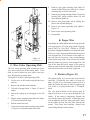
Section
5
E
MAINTENANCE,TROUBLE
SHOOTING AND
ADJUSTMENTS
D
A
General
C
The M2000 Stitcher is a friction-type head which
depends on smooth sliding friction and proper timing to function correctly. Preventative maintenance
will go far to insure trouble-free operation. Avoid
production down time by keeping your stitcher lubricated and in top working condition at all times.
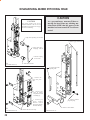
Figure 6
MAKE ALL ADJUSTMENTS
WITH THE POWER OFF AND
THE STITCHING HEAD IN
NEUTRAL POSITION! (Fig. 6)
Like any equipment that has moving parts, certain
parts of your stitcher will be subjected to more wear
than others and require replacement. The following listing includes all the parts required for minimum maintenance and good operation.
Wire Cutters
Grip
Grip Spring
Tension Roll Clip
Rotator
Clincher Points
In neutral position, the wire grip assembly (Index A) is stopped at the top of the
slot in the face plate.
QTY.
2
1
1
2
1
2
(CTTT22605 Scenes 5 & 9)
Caution
Recommended Spare Parts
PART NAME
Figure 7
(CTTT2605 Scene 8)
Stitching Adjustments
Best stitching performance will be assured if all
adjustments are made so that you get the following
results:
1.
2.
3.
4.
5.
Good Cut-Off
Uniform Wire Draw
Equal Leg Length
Proper Clincher Alignment
Sufficient Compression
To Equalize Both Legs of Stitch
(Figure 7)
8
1.
Loosen the wire guide locking bolt (Index C).
2.
Turn adjusting screw (Index D) clockwise to
shorten left leg of stitch; counter clockwise to
lengthen left leg.
3.
Tap bracket (Index E) down before tightening
screw (Index C).
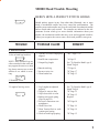
M2000 Head Trouble Shooting
HERE'S HOW A PERFECT STITCH LOOKS
Should stitches appear in any form other than illustrated, one or more
kinds of mechanical trouble may have caused the malformation. The
possible causes and remedies are given for each kind of mechanical trouble
and are listed under each section. The remedies are indexed to the Adjustments Section which gives more detailed information about your
stitcher, the mechanical trouble that may occur and suggested remedies.
Unless you recognize the correct cause, check each possible cause given.
TROUBLE
POSSIBLE CAUSE
REMEDY
A. Defective Stitches
1. One or both legs buckled.
NOTE: Since buckled legs are
often concealed in the work and
may appear the same as a short
leg, always remove two or more
stitches to see which is occurring.
1. Clincher is worn or improperly
aligned.
"B,C" Page 12,13
2. Insufficient compression.
"A Page 12
3. Unequal leg length
See "To Equalize Both Legs of
Stitch" Page 8
4. Burred stitch leg.
"I" Page 16
5. Incorrect wire size.
"K" Page 17
6. Worn bender bar.
"D" Page 13
1. Leg Lengths not adjusted
properly
2. Gripper is worn or dirty
3. Grip release slide is worn
4. Broken wire guide spring
(Figs 20 page 22)
5. Excessive tension on wire
straightener
6. Worn Driver bar
7. Worn Tension Pawl or weak
tension pawl spring
8. Weak or broken grip spring
See "To Equalize Both Legs of
Stitch" Page 8
"H" Page 15
"H" Page 15
Replace
2. Wrinkled crown.
3. Length of one leg varies
"M" Page 18
"F" Page 14
"O" Page 19
"H" Page 15
9
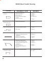
M2000 Head Trouble Shooting
TROUBLE
4. Corner of crown distorted or
fractured
POSSIBLE CAUSE
1. Excessive compression
2. Broken driver end
3. Worn bender bar
4. Clincher improperly aligned
or worn
5. Incorrect wire size
5. Stitch crown not flat and legs 1. Insufficient compression
not bent into work
6. One or both legs turn out
7. Flat piece of wire
8. Stitches come out in pieces
9. Both stitcher legs are either
too long or too short
10
REMEDY
"A" Page 12
"G" Page 15
"D" Page 13
"B,C" Page 12,13
"K" Page 17
"A" Page 12
1. Clincher improperly aligned
"C" Page 13
2. Dull cutters
"I" Page 16
1. Rotator is dirty
2. Improperly adjusted lower wire
straightener
3. Broken or worn rotator
4. Improperly aligned rotator
"L" Page 17
"M" Page 18
1. Improperly aligned rotator
2. Weak rotator operating spring
3. Improperly adjusted upper wire
straightener
4. Incorrect wire size
5. Wire jammed in bender bar
grooves
"L" Page 17
"L" Page 17
"M" Page 18
Face plate not adjusted properly
See "Changing Work Thickness" Page 7
"L" Page 17
"L" page 17
"K" Page 17
"D" Page 13
M2000 Head Trouble Shooting
TROUBLE
POSSIBLE CAUSE
REMEDY
B. WIRE BUCKLES
1. Wire buckles above the grip
and below the tension pawl
1. Worn driver bar
"F" Page 14
2. Worn bender bar latch
"G" Page 15
3. Worn or broken bender bar
friction plug and/or spring
"E" Page 14
(CTTT2605 Scene 10 VA)
2. Wire Buckles above the
wire cutters and below the
grip
1. Improperly aligned rotator
"L" Page 17
2. Worn or broken wire cutters
"I" Page 16
3. Burrs on rotator
"L" Page 17
4. Improperly adjusted lower
wire straightener
"M" Page 18
5. Worn or broken wire cutter
operating slide
"J" Page 17
6. Wire cutter slot in face plate
worn
"I" Page 16
1. Face plate is too high
See "Changing Work Thickness" Page 7.
(CTTT2605 Scene 10 VB)
C. GRIP
1. Grip does not close
11
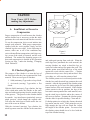
CAUTION
STITCH
Turn Power OFF Before
making Any Adjustments
A. Insufficient or Excessive
Compression
Proper compression of work between the clincher
and the bender bars is necessary so that the stitch
penetrates the work material and clinches correctly.
To test for compression, drive several stitches into
sample work material. With proper compression,
stitches hold the work together firmly and the
clinched legs do not overlap. In the following instances, either one or all of the conditions may
exist: with insufficient compression, stitch legs overlap, crown of the stitch is fractured, and the work
mutilated. The method for obtaining proper wire
draw and compression is detailed in the Operation
Section on Page 7 under the heading, "Changing
Work Thickness".
B. Clincher (Figure 8)
The purpose of the clincher is to turn the legs of
the stitch back after they have penetrated the work
material. There are two types of clinchers:
1. Solid (stationary) Type-makes a loop clinch.
2. Activated (moving) Type-makes a flat
clinch.
With the Solid (stationary) Type clincher, the legs
of the stitch must strike the clincher at the same
time and with equal spacing from the outside edges
of the grooves. The grooves in the clincher should
be smooth. Any interference (particularly worn or
pitted grooves), which change the original radii,
will cause the stitch legs to buckle and/or the corners of the crown to fracture.
With the Activated (moving) Type clincher, the
stitch legs must enter the clincher at the same time
12
ACTIVATED
STITCH
SOLID
Figure 8
(SK852F)
and with equal spacing from each side. When the
stitch legs have penetrated the work material, the
moving clinchers are raised to bend the legs towards each other and up flat against the work. The
clincher points must bend both legs of the stitch
against the work with the same force. Clincher
points must always move freely and not bind. Dirt,
wire chips, etc. will cause the points to bind.
The clincher points are in a retracted position in the
clincher box until the stitch legs penetrate the work
material. After the legs penetrate, the clincher points
move upward to give a neat, flat clinch against the
bottom surface of the work material. If the clincher
points remain in the up position, the legs of the
next stitch cannot penetrate the work material, causing the stitch legs to buckle and/or the corners of
the crown to fracture. Examine the clincher points,
clincher slide for possible binding. Clean and oil.
If clincher points rise to high, they fracture the stitch
legs and/or mar the work. If the points do not rise
high enough, the legs will not clinch flat. Adjust
the height of the clincher points. For most work
the clincher points should rise to be level with the
top of the clincher housing.
Inject lube into cutter operating slide.
D
Figure 9
(CTTT2605 Scene 11)
Figure 11
(SK852I)
2. To adjust for side-to-side alignment: (Fig. 10)
A
Figure 10
(CTTT2605 Scene 12)
a. Turn power off. Cycle the stitcher by hand
until legs of the stitch appear just below the
bender bar to determine how far the head or
clincher should be moved to the side.
b. Loosen clincher plate binder nuts (Index A).
C. Head/Clincher Alignment
(Figure 9, 10)
c. Move clincher to left or right as required.
To test alignment: Drive several stitches into a section of material identical to that which is to be
stitched. The clinched legs should be identical and
aligned with each other. If the legs are not in alignment make one of the following adjustments:
D. Bender Bar (Figure 11)
1. To adjust for front-to-rear alignment: (Fig. 9)
a. Turn power off. Cycle the stitcher by hand
until legs of the stitch appear just below the
bender bar to determine if the head should
be moved to the front or rear.
b. Remove stitcher from machine.
c. Turn the head aligning screw (Index D)
clockwise to move the head backward; counterclockwise to move the head forward.
d. Install stitcher head on machine.
d. Tighten binder nuts.
The bender bar bends the wire over the rotator and
forms it into an unclinched stitch. The legs of the
stitch are guided towards the work material by the
bender bar grooves. The legs of the unclinched
stitch should be perpendicular to the crown. When
the bender bar grooves become worn, the legs tend
to flare out (Figure 11) as they emerge from the
grooves. This causes the legs to strike the clincher
improperly. As a result, one or both legs will
crumple and a broken driver bar or a broken bender
bar can result. If the lower end of the bender bar
grooves become chipped, it will not support the
wire and may cause the stitch to break at the crown.
Replace the bender bar assembly (See "G" page 15
or Fig. 12). Other bender bar functions are related
to wire cutting ("I" page 16), and driving ("F" page
14).
13
A
B
C
B
A
D
F
G
Figure 12
(CTTT2605 Scene 13)
E
E. Bender Bar Friction Plug
And/Or Spring (Fig.12)
Two parts furnish pressure to coordinate movement
of driver bar and bender bar. If pressure is insufficient, proper timing is not maintained for the action
of the grip. As a result, wire feeds backwards.
Replace the plug and/or spring.
To replace bender bar friction plug and/or bender
bar friction spring:
1.
Remove bender bar assembly by following
steps 1 through 18 of "Dismantling M2000
Stitching Head", Pages 20 and 21.
2.
Remove bender bar friction bushing (Index A).
Bender bar friction plug (Index C) and spring
(Index B) will be released forward from bender
bar assembly.
3.
Replace plug and/or spring and reassemble.
F. Driver Bar (Figure 13)
The driver bar (Index A) has several functions:
1.
It imparts the downward thrust from the driving
slide assembly (Index B) to the bender bar
assembly (Index C).
2.
It returns these parts to the neutral position on
the upstroke.
14
C
Figure 13
(CTTT2605 Scene 14)
3.
In conjunction with the grip release slide (Index
D), it controls the movement of the bender bar
latch (Index E) that opens and closes the grip
(Index F).
If the notches (Index G) at the top left side of the
driver bar become worn, the grip will not remain
open on the upstroke. As a result the wire feeds
backwards and buckles above the grip and below
the tension pawl. Worn notches can also cause
uneven wire draw. Replace the driver bar.
The notches shown on left side of driver bar play
an important part in function of bender bar assembly therefore, corners should be free of dirt and
notches not marred.
The driver bar rides within the bender bar grooves
as part of the bender bar assembly. As this assembly reaches the lower contact point of the cam in
the grip release slide, the bender bar latch is forced
inward, releasing the wire grip and permitting the
bender bar assembly to continue downward with
the end of the driver riding on top of the formed
E
F
D
B
X
C
A
Figure 14
(CTTT2605 Scene 15)
stitch. When the bender bar is stopped against the
work material, the driver bar continues downward
to exert pressure on the crown of the stitch, driving
it through the work material.
If the end of the driver bar is chipped it allows the
legs of the stitch to back up into the broken area.
This causes the corner of the crown to fracture or a
"spike" section to protrude above the crown. A
chipped driver bar is usually the result of driving a
stitch on top of another stitch. A worn driver often
causes deformed stitches or fracturing at the corners of the crown.
G. Bender Bar Latch
The bender bar latch opens and closes the grip and
is actuated by the grip release slide and driver bar.
If the contact points of the latch become worn, tim-
ing of the grip is erratic and uneven wire feed results. A dirty latch will decrease preassure of the
grip on the wire. This causes wire slippage. Clean
or replace the latch.
H. Grip, Grip Release Slide and
Face Plate: (Figure 14)
The grip spring (Index A) exerts pressure on the
benderbar latch (Index B) to close the grip (Index
C) at the start of the down stroke. The grip release
slide (Index D) actuates the bender bar latch at point
X to open the grip after the correct amount of wire
has been fed to make a stitch. The serrated teeth on
the grip must be sharp or slippage will occur, producing uneven wire draw.
15
When the face plate (Index E) is adjusted (See
"Changing Work Thickness", page 7) a pivotal action (at point F) changes the position of the grip
slide. When the face plate is raised, it moves the
grip release slide down. The gripper can then remain closed longer, on the down stroke, feeding
more wire for the stitch. When the face plate is
lowered, it moves the grip release slide up. The
gripper will open sooner on the down stroke, feeding less wire for the stitch.
If the grip is weak, uneven wire draw will result.
Replace the grip spring. If the contact points on
the grip release slide and/or the bender bar latch
are worn, wire adjustment will not remain accurate.
The face plate stops the bender bar assembly at the
top of its stroke and allows the bender bar latch to
close the grip. When the face plate is too high, too
much of the upstroke has been used before the
bender bar hits the face plate. In the remaining
portion of the upstroke, the driver bar cannot continue upward enough to release the bender bar latch
so that it can close the grip.
I
M
E
A
D
H
L
K
N
J
I. Wire Cutters: (Figure 15)
The purpose of the wire cutters is to shear the wire
cleanly. There are two wire cutters, upper and
lower. The upper wire cutter (Index A) receives
wire from the grip through the wire cutter lead-inhole (Index B). It also serves as the cutoff die.
The lower wire cutter (Index C) is the cutting knife.
If the cutter breaks, it will cover the lead-in hole.
This prevents the wire from feeding into the rotator. If the cutting surfaces become worn, burrs will
result on the end of the wire. This prevents the
wire from feeding into the rotator. As a result, the
wire buckles between the cutters and the wire grip.
Reverse, interchange or replace the cutters.
To Reverse, Interchange or
Replace the Wire Cutters:
1.
Loosen both face plate retaining clips (Index
D) at bottom of bonnet.
2.
Spring the face plate out 1/8" while holding
the cutter slide in position (Index E).
3.
Slide the cutters out to the left.
16
4.
F
C
B
G
Figure 15
(CTTT2605Scene 16)
Reverse, interchange or replace the cutters.
NOTE
While installing the cutters, make sure that (1): lip
on upper cutter (Index F) fits into the recess behind
the face plate (Index G) and (2): that the lip on the
bottom cutter fits into the slot (Index H) in the wire
cutter operating slide (Index I).
The wire cutter operating slide actuates the lower
wire cutter. If the slide is worn or broken, the wire
cutter is not actuated. Replace the operating slide.
The slot in the lower part of the face plate contains
the wire cutter and maintains a close fit for wire
shearing. If this slot becomes oversized, the wire
will not be cut off. Replace face plate. To Replace Face Plate (See Steps 1 through 10, "J"
page 17).
NOTE: (Figure 16)
The lug (Index C) in the faceplate must match
the slot (Index D) in the grip release adjusting
lever (Index E) or damage to the head may result.
E
D
F
8.
Push two face plate retaining clips (Index F)
outward while lifting face plate up, or remove
retaining clips to release face plate.
9.
Position grip spring housing (Index G) between
tension pawl spring retainer (Index H) and
cutter housing (Index I).
10. Remove face plate (Index B) by sliding face
plate to the left and lifting up.
11. Remove the cutter operating slide (Index I,
Figure 15).
12. Insert a new cutter operating slide.
C
13. Reassemble
G
B
K. Proper Wire
A
H
I
Figure 16
(CTTT2605 Scene 17)
J. Wire Cutter Operating Slide
The wire cutter operating slide actuates the lower
wire cutter which acts as the cutting knife. If the
slide is worn or broken, the wire cutter is not actuated. Replace the operating slide.
To Replace The Wire Cutter Operating Slide:
1.
Cut the wire at the bracket and pull the loose
end out.
2.
Remove the stitcher head assembly.
3.
Lift end of spring (Index L, Figure 15) out of
rotator.
4.
Swing the spring up to disengage it and lift
out.
5.
Slip the rotator operating cam (Index M, Figure
15) forward and off the stud.
6.
Pull the rotator forward.
7.
Loosen the two face plate retaining clips (Index
A, Figure 16) and rotate them downward.
Depending on which M2000 head is being used the
wire range may be: 25 to 30 gauge round; 24 gauge
round; 20x25 or 21x25 flat. 120,000 to 159,000
psi tensile strength bookbinders wire should be used.
If the wire used is larger than the bender bar grooves
were designed for, it will fracture at the stitch corners and come out in pieces. Also, serious damage
to the stitcher may result. If the wire used is smaller
than the bender bar grooves were designed for, the
legs of the stitch do not fit snugly in the grooves
and may tend to buckle when they strike the work
material because they are not fully supported.
L. Rotator (Figure 15)
The rotator (Index J) (1) receives the wire from the
cutoff die, (2) holds the wire while it is being cut,
then (3) turns it to a horizontal position, moves it
under the bender bar grooves and (4) supports the
wire while it is being formed into a "U-shaped"
stitch.
The wire lead-in-funnel of the rotator must be
aligned with the wire as it comes through the wire
cutters. If the rotator is improperly aligned, the
wire hits the rotator and buckles. Adjust upper two
wire straighteners until wire slips past rotator. Burrs
on the rotator prevent the wire from entering the
rotator. This causes wire buckling. Remove the
rotator and polish the lead-in radius.
17
The magnets in the rotator hold the wire firmly in
the rotator. If a magnet is broken or chipped the
wire may fall out. To determine if the rotator has
the proper holding strength, remove the rotator and
insert a cut length of wire in the rotator. Hold
rotator between thumb and forefinger. Attempt to
jar wire loose by hitting heel of hand on top of
table or against other hand. With proper magnetic
holding force wire will remain in rotator. With
insufficient holding force wire will fall from rotator. Replace the rotator.
The rotator holder and rotator operating spring are
responsible for alignment of the wire beneath the
bender bar grooves. The position of the rotator
holder determines how far the rotator is pushed
forward under the bender bar by the rotator operating spring (Index L, Figure 15). A weak spring
will not push the rotator in far enough and with this
improper alignment the bender bar will knock the
wire from the rotator or will shear the wire into
pieces. To secure proper alignment, check the position of the rotator holder and the tension applied
by the rotator operating spring. Make any necessary adjustment of the rotator holder or replace the
rotator operating spring if weak.
The wire is fed into the rotator and held for forming. If the rotator is dirty, the wire is not gripped
securely enough and drops out. Remove and clean
the rotator. If the edges over which the wire is
formed are sharp, the corners of the stitch crown
will fracture. Remove the rotator and polish the
edges with a fine emery cloth.
To remove, Adjust or Replace the Rotator Holder:
1.
Swing the rotator operating spring to the left.
2.
Remove the rotator.
3.
Loosen the rotator holder screw (Index N,
Figure15).
4.
Adjust the rotator holder.
5.
Reassemble.
18
A
B
D
C
Figure 17
(CTTT2605 Scenes 3 &4)
M. Wire Straighteners:
(Figure 17)
All coils of stitching wire have a certain amount of
bundle curve. The purpose of a wire straightener is
to remove this curve. There is both an upper wire
straightener (Index A) and a lower wire straightener (Index B) on all M2000 Model Stitchers. See
"Threading Wire and Adjusting Wire Straighteners" page 4.
The upper wire straightener should feed wire parallel to the faceplate. This insures that the wire will
properly enter the rotator and will be aligned with
the grooves in the bender bar.
If the wire is not parallel to the face plate the wire
is sheared in the rotator as the bender bar descends.
Adjust the upper wire straightener.
The lower wire straightener directs the wire straight
down so that it enters the rotator (Index C). If the
wire is not straight enough it hits the rotator and
buckles. Adjust the lower wire straightener so that
A
B
A
Figure 18
Figure 19
(CTTT2605 Scene 11)
the wire points straight down as in figure 17. Improper straightening of the wire can also cause the
stitch legs to buckle or turn out because they strike
the clincher improperly. Excessive tension on the
wire straightener prevents the grip (Index D) from
feeding the wire smoothly. This causes variation
in leg length.
NOTE:
Check the wire straighteners when changing the
coils to insure the accurate feeding of wire.
(CTTT2605 Scene 18)
If the corners of the top surface of the supporter are
too sharp, or nicked, the corners of the stitch crown
will fracture. If operating properly the supporter
should function as follows:
1.
When the bender bar touches the work material
and the legs of the stitch are about to leave
the bender bar grooves the supporter should be
touching the underside of the crown.
2.
As the stitch is driven through the work the
supporter is gradually retracted by the driver.
It should remain under the crown of the stitch
until the last instant before the crown touches
the work material.
N. Supporter
O. Tension Pawl: (Figure 19)
The supporter furnishes the necessary support to
the inside surface of the stitch so that it does not
buckle as it is being driven into the work material.
A lack of (or insufficient) support will often cause
the stitch crown to wrinkle or the legs of the stitch
to buckle. Tighten the supporter spring bushing
(Index A, Figure 18) or replace the spring.
The tension pawl (Index A) and spring (Index B)
apply pressure on the wire to prevent back feed. If
the pawl becomes worn or the spring becomes weak,
the wire feeds backwards resulting in a short wire
draw. Reverse or replace the tension pawl and/or
spring.
19
DISMANTLING M2000 STITCHING HEAD
CAUTION
CAUTION
As a precautionary measure-When removing the head from any stitching machine make SURE that the power to the
machine has been turned OFF or disconnected.
The rotator operating cam can be
installed backwards. Be sure to read
and follow the instructions "F"on page
21 before reassembling.
3. Slip rotator operating cam off stud.
11. Remove grip release slide.
2. Swing spring up to
disengage. Lift out
1. Lift end of spring
out of rotator
A
(CTTT2605 Scene 19)
4. Pull rotator forward
9. Remove the cutter
operating slide
5. Remove the
upper face plate
clips.
8. Remove face
plate by sliding
face plate to the left
and lifting up.
10. Remove friction
plug and spring.
7. Position grip
spring
housing
between tension
pawl spring retainer
and cutter housing
B
(CTTT2605 Scene 20)
20
6. Remove the two lower clips.
C
(CTTT2605 Scene 21)
12. Remove rotator holder.
DISMANTLING/REASSEMBLING M2000 HEAD
17. Loosen face plate clamp screw
and slide out face plate locating block.
15. Remove screw
16. Slide tension spring bracket
and adjusting lever from top.
18. Slide the driving slide and bender
bar assemblies from the top. When
reassembling, hook bender bar to
driving slide before sliding into place.
This must be assembled as a complete
unit.
13. Remove rotator
operating cam stud
screw.
14. Remove
r o t a t o r
operating cam
stud.
D
(CTTT2605 Scene 22)
Caution
DO NOT
REMOVE
OR ADJUST
THESE
TWO
SCREWS.
A
B
The screws
are factory set
to control the
supporter
lever location.
E
(CTT2605 Scene 5)
C
When reassembling,
make certain that pin
(Index A) is visible
and is aligned with
slot (Index B) of
rotator operating cam
(Index C).
If not
assembled in this
way, the bonnet
casting will crack or
break on the next
cycle under power.
It is recommended
that the stitcher be
cycled by hand to
test that proper
r e a s s e m b l y
procedure has been
followed.
F
(CTTT2605 Scene 23)
21
Section
32
6
24
30
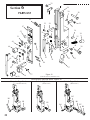
PARTS LIST
28
31
45
32
29
32
47
31
53
34
40
31
36
35
51
42
49
60
52
40
54
55
41
48
43
61
49
50
32
33
39
44
46
59
58
38
56
Clamp-On-Type Head
(CTTT2605 Scene 25)
57
37
Figure 19
(CTTT2605 Scene 24, CB75B Iso View)
Bolt-On and Clamp-On Heads Figures 20
Bolt-On-Type Head
(SK885 Scene 2)
Bolt-On-Type Head
(SK885 Scene 1)
B5
B1
B2
B3
B6
B4
B7
B8
22
2
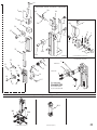
Adjustable Stroke Position Components
2A
1A
4A
1
3
6A
5A
27
s
1B
26
25
q
7A
i
23
25A
26A
(SK852R)
j
m
n
(CAAA9074A2 Layout 2)
CTTT2606R3-Assembly
22
20
21
10
19
p
h
8A
9
r
11
12
13
20
(NEW PART)
CT413E
(NEW PART)
2 x CA9024E
14
18
15
Full Assembly
Full Assembly
CAAA9013Z5
also
includes items:
CAAA9013Z5
17 16
11,12,13,14,15,21,22
16
(NEW PART)
CAA9013U5
Special Components Figures 21
B11
B9
B10
(CTT2604L Layout 2)
(CA44 Layout 2)
23
M2000 HEAD
PARTS LIST
ITEM PART NO.
DESCRIPTION
QTY
ITEM PART NO.
1
1A
1B
CAA9074Z
CTT2615B
CAAA9074A2
1B
h
i
j
k
m
n
p
q
r
s
CAA9074A2
CA9146A
CA9068
CA9065
CA9070
CA9069
CA9067
D31028F
CA9103C
CA9124
CA9076
WIRE GUIDE BRACKET ASSEMBLY
1
WIRE GUIDE BRACKET ASSEMBLY
1
WIRE GUIDE BRACKET ASSEMBLY
1
NOTE: The above Wire Guide Bracket assembly
includes the following items h through s
WIRE GUIDE SRACKET SUB-ASSEMBLY
1
ECCENTRIC SCREW
1
ECCENTRIC FRICTION BUSHING
1
ECCENTRIC ROLL
1
ECCENTRIC POINTER
1
ECCENTRIC SPRING
1
ECCENTRIC NUT
1
SET SCREW
1
WIRE STRAIGHTENER ROLL
1
TENSION ROLL CLIP
2
WIRE GUIDE SPRING BRKT ADJ SCREW
2
2
2A
3
4A
5A
6A
7A
8A
CA9076
CT56
CA9077
CT1060
CT2616
CT2614
CT2612
CT2610
WIRE GUIDE SPRING BRKT ADJ SCREW
WIRE GUIDE SPRING BRKT ADJ SCREW
WIRE GUIDE SPRING BRKT SET SCREW
SET SCREW
WIRE GUIDE BRACKET ADJ. SCREW STUD
FACE PLATE ADJ. SLIDE GUIDE STUD
FACE PLATE LOCATING BLOCK STUD
FACE PLATE ADJUSTING SLIDE
9
See TABLE 1 DRIVING SLIDE ASSEMBLY
NOTE: The Driving Slide Assembly includes the following parts:
DRIVING SLIDE (ONLY)
a,c,d,fCA-2623 (standard)
b
CT-2623 (2 sheets to .125 in. thick work)
e
CA-2623-B (pin holds in driving slide spring)
DRIVING SLIDE SPRING PLUNGER
a,b,c,d,f
CA-2007
e
CA-2007-A
DRIVING SLIDE SPRING
a,b,c,d,f
CA-9006
e
CA-9006-A
DRIVING SLIDE SPRING SCREW
a,b,c,d,f
CA-9021-A
DRIVING SLIDE SPRING PIN
e
D-37327-F
DRIVING SLIDE ROTATOR OP. PIN
all
CA-9028
DRIVING SLIDE SPRING SCREW LOCK PIN
a,b,c,d,f
CA-9028-A
1
1
1
1
1
1
1
1
DESCRIPTION
QTY
a
b
c
d
e
f
11
12
13
CAA9013U
CAA9013Z
CAA9013F2
CAA9013H2
CAA9013K2
CAA9013P2
CA9115
CA9113A
CA9112A
BENDER BAR SUB ASSEMBLY
1/2" Cr., 25 to 30 rd. wire
1/2" Cr., 25 to 30 rd. wire (McCain, Macey)
1/2" Cr., 24 rd. wire
1/2" Cr., 20-21 x 25 wire
1/2" Cr., 24 rd. wire (McCain)
1/2" Cr., 22 rd. wire
BENDER BAR FRICTION PLUG BUSHING
BENDER BAR FRICTION PLUG SPRING
BENDER BAR FRICTION PLUG
14
CAA9026
SUPPORTER ASSEMBLY, 1/2" Cr.
1
15
16
17
18
or
19
or
20
21
22
CA9029
CA168
CB371K
CA9024A
CA9024E
CT413A
CT413E
CA9015D
CA173
SUPPORTER PIVOT PIN
EXTERNAL GRIP SPRING
LOCKWASHER
GRIP HOUSING RET. SCREW
GRIP HOUSING RET. SCREW (CAAA9013Z5)
GRIP SPRING HOUSING
GRIP SPRING HOUSING (CAAA9013Z5)
GRIP
PLASTIC PIN CAP
BENDER BAR LATCH
Standard
Special for CAAA9013D3 & CAAA9013M3
Bender Bar Assemblies (McCain)
1
1
1
1
1
1
1
1
1
1
DRIVER BAR
1/2" Cr.. 25 Round Wire
1/2" Cr. (McCain), 25 Round Wire
1/2" Cr., 20x25 & 21x25 Flat Wire
1
CAA9014J
CAA9014N
23
1
1
1
1
1
CA9012M
CA9012N
CA9012R
24
BONNET CASTING SUB ASSEMBLY
*
M2000 Heads that use bonnet sub assembly
CAA2004
CAAA2005,B,R
CAA2004B
CAAA2005J
CAA2004E
CAAA2005F, G (R.H. HEAD)
CTT2604
CTTT2605,A2,C,E3,G,O,R2,R3,R10
CTT2604F
CTTT2605F4
CTT2604L
CTTT2605Q3
CTT2604P
CTTT2605P2,P4
1
25
1
1
1
CT2608
CT2608A
25A CT2613
26 CT2606
26A CT2611
27 CT2607
28 CA9075
29 CA9127
30 CA9058
31 CA9056C
32 CA2081
33 CA9056A
FACE PLATE LOCATING BLOCK SCREW
Slotted head (shown)
5mm Hexagonal socket head (not shown)
FACE PLATE LOCATING BLOCK NUT
FACE PLATE LOCATING CLAMP
FACE PLATE ADJ. SLIDE BLOCK
FACE PLATE LOCATING BLOCK
WIRE GUIDE BRACKET SCREW
ROTATOR OPERATING CAM STUD
ROTATOR OPERATING CAM STUD SCREW
FACE PLATE RETAINING CLIP
FACE PLATE RETAINING CLIP SCREW
FACE PLATE RETAINING CLIP
TABLE 1 (For use in determining customer's Driving Slide Assembly)
9
a
b
c
d
e
f
24
DESCRIPTION
DRIVING SLIDE ASSEMBLY
CTT2623
CTT2623A
CTT2623C
CAA2623
CAA2623C
CAA2623D
1
1
1
1
10
BENDER BAR ASSY. COMPLETE
1
a
CAAA9013Z2 1/2" Cr., 25 to 30 rd. wire
b
CAAA9013D3 1/2" Cr., 25 to 30 rd. wire (McCain)
c
CAAA9013H3 1/2" Cr., 24 rd. wire
d
CAAA9013K3 1/2" Cr., 20-21 x 25 wire
e
CAAA9013M3 1/2" Cr., 24 rd. wire (McCain)
f
CAAA9013R3 1/2" Cr., 22 Rd. wire
g
CAAA9013Z5 1/2" Cr., CTTT2606R3
NOTE: The above Bender Bar Assembly includes the following items
through item 23
ITEM PART NO.
1
Driving Slide Style/Use
standard, raised lug
lowered lug for 2 sheets to .125 in. thick work
standard, raised lug
standard, raised lug
pin (D37327F) holds in driving slide spring
standard, raised lug
Lug Style
.187 lg. rectangular (CT2602)
.187 lg. rectangular (CT2602)
.25 lg. rectangular (CT2602A)
round (CA2103) w/.031 thk. washer (CT32B)
round (CA2103) w/.031 thk. washer (CT32B)
round (CA2103B) w/.079 thk. washer
* Contact ISP customer service for M2000 heads not listed
1
1
1
1
1
1
1
3
4
1
M2000 HEAD
PARTS LIST
ITEM PART NO.
34
35
36
SUPPORTER SPRING LEVER ASSEMBLY
Standard (1.625 in. long)
Special (1.494 in. long)
Special (1.312 in. long)
1
CAA9036
CAA9036A
CAA9036B
CA9034
SUPPORTER SPRING LEVER SCREW
1
2
CA9030
CA9030A
SUPPORTER GUIDE PLATE
All except listed below.
CTTT2605A2 (McCain)
48
49
50
51
52
53
54
55
40
41
CA9081
CA9051A
42
CA9050A
44
SUPPORTER GUIDE PLATE SCREW
WIRE CUTTER OPERATING SLIDE
FRICTION PLUG SPRING
WIRE CUTTER OPERATING SLIDE
FRICTION PLUG
2
1
QTY
CAA2132V
CAA2132W
CAA2132Y
CA9134
CA9124
CA9103A
CA9103C
CA9098
CA9065A
CA9066A
CA172
1
ROTATOR HOLDER
1/2" CR., 25 TO 30 RD. WIRE, TAPERED END
1/2" CR., 25 TO 30 RD. WIRE
1/2" CR., 20-21X25 WIRE
1/2" CR., 25 TO 30 RD. WIRE, R.H. (Not Shown)
1
CA9043M
CA9043L
CA9043N
CA9043P
1
4
1
2
1
1
1
1
1
CA9022J
GRIP RELEASE SLIDE, 1/2" Crown
1
FACE PLATE ADJUSTING LEVER
For Non-Slotted Face Plates
For Slotted Face Plates
1
CA9025
CA9025D
CA9048
WIRE CUTTER
2
1
CAAA2132V
CAAA2132W
CAAA2132Y
FACE PLATE ASSEMBLY
1/2" Crown, Slotted
1/2" Crown, No Slot
1/2" Crown, Fixed (Bypass)
47
DESCRIPTION
FACE PLATE SUB ASSEMBLY
1/2" Crown, Slotted
1/2" Crown, No Slot
1/2" Crown, Fixed (By-Pass)
TENSION PAWL SPRING
TENSION ROLL CLIP
CHECK PAWL ROLLER
WIRE STRAIGHTENER ROLL
TENSION PAWL
STRAIGHTENER ECCENTRIC ROLL
WIRE STRAIGHTENER ECCENTRIC
ECCENTRIC FRICTION LOCKING SCREW
56
WIRE CUTTER OPERATING SLIDE
1
CA9049
1/2" Cr. (All 1/8", .155", 3/16" capacity heads, and
CTTT2605F4,H4 heads.)
CA9049A
1/2" Cr. (All other 1/2" Cr Heads not listed above)
45
46
ITEM PART NO.
47
39
43
QTY
BONNET ALIGNING SCREW
0 to 2 as req'd.
SUPPORTER SPRING
1
SUPPORTER SPRING BUSHING
1
37
38
DESCRIPTION
CT9109
CA9032C
CA9037
57
CB75B
KEY, WOODRUFF
(for use with CA-9043-M Rotator Holder only)
1
58
CAA9038E
M2000 ROTATOR, 1/2" CROWN
1
ROTATOR HOLDER SCREW
all except below
CTTT2605W2,Y2,Z2,A3,X3,R7
CAAA2005K
1
CA9044A
CA9044B
ROTATOR OPERATING CAM
standard oiling
inverted oiling
1
ROTATOR OPERATING SPRING ASSEMBLY
HEAD OPERATING LINK
(For use only with round lug driving slide
assemblies)
1
1
59
60
CA9163C
CA9163D
61
62
CAA9046D
CA44
NOTE: The above face plate assemblies include indexes 47 to55
TABLE 2
(For use in determining customer's special components)
ITEM PART NO.
DESCRIPTION
QTY
USAGE
B1
B2
B3
CTT9003C
CTT9002
CB157
BONNET CLAMP LEVER
BONNET CLAMP ASSEMBLY
BONNET BINDER SCREW
1
1
1
CTTT2605,C,G,R3,F4
CTTT2605,C,G,R3,F4
B4
CB835Q
ROLL PIN
1
CTTT2605P2,P4,Q3,R2
BONNET BINDER STUD
.500-13 NC Thread
M8 X 1.25-8g Thread
1
CT9002A
CT9002F
TEE BAR
.625 Long
.841 Long
1
CT9002G
CT9002L
CB175
CB145A
CT9109A
CT9111
CA44
WASHER
NUT, .500-13 NC
BONNET ALIGNMENT PIN
CONE POINT SET SCREW
HEAD OPERATING LINK
1
1
2
2
1
B5
B6
B7
B8
B9
B10
B11
CTTT2605R2
CTTT2605P2,P4,Q3
CTTT2605P2
CTTT2605Q3
CTTT2605P2,Q3
CTTT2605R2
CTTT2605Q3
CTTT2605Q3
CTTT2605R2 (For use only with round lug driving slide assemblies)
25
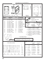
CLINCHER PLATE ASSEMBLIES
30°
TYPE A1, A2, A3
Chamfered
A3
A1 A2
TYPE B
CROWN
SIZE
CLINCHER
POINT
TYPE
1/2
1/2
1/2
1/2
1/2
1/2
1/2
1/2
1/2
1/2
1/2
1/2
CA-9083 Thin
CA-9083-A Thick
CA-9083 Thin
CA-9083-A Thick
CA-9083-A Thick
CA-9083-A Thick
CA-9083-A Thick
CA-9083-A Thick
CA-9083 Thin
CA-9083-A Thick
CA-9083 Thin
CA-9083-A Thick
A1
A1
A1
A1
A2
A2
A3
A3
B
B
C
C
TYPE C
(SK852G2)
(CTT9086A Layout 2, CTT9086M Layout 2, CTT9086V Layout 2)
(SK852H2)
CLINCHER
PLATE ASSY.
CTT-9086
CTT9086-A
CTTT-9086*
CTTT9086-A**
CTTT9086-M***
CTT9086-M
CTTT9086-V****
CTT9086-V
CTT-9086-B
CTT9086-F
CAA-2089
CAA-2089-A
CA9085A
Clincher Guide Plate
(CA9085A Layout 2)
CA-2090
Stud
(SK852J2)
CT-9088
Binderbolt
(SK852K2)
CA-2091
Nut
(SK852L2)
* Includes CA-9083, CTT-9086,
CT-9093, CA-2091, CT-9088.
** Includes CA-9083-A, CTT-9086-A,
CT-9093-A, CA-2091, CT-9088.
*** Includes CA-9083-A, CTT-9086-M,
CT-9093-A, CA-2091, CT-9088.
**** Includes CA-9083-A, CTT-9086-V,
CT-9093-A.
CLINCHER POINT
1/16 Nominal, CA-9083-A, Thick, 1/2 Crown
1/32 Nominal, CA-9083, Thin, 1/2 Crown
(SK852I2)
CLINCHER SLIDES
L
D
L
E
(SK852M2) (SK852N2)
26
L
L
F
(SK85202)
G
(SK852P2)
L
H
J
(SK852Q2)
(SK852R2)
TYPE
L
D
D
E
E
F
G
H
J
3-17/32
3-37/64
5-9/16
5-9/16
3-31/64
12-25/32
12-25/32
3-17/32
Adjustable
CLINCHER CLINCHER
SLIDE
POINT
CT-9093
CT-9093-A
CT-9093-R
CT-9093-S
CA-2095-G
CA-2095-A
CA-2095
CTT-9093-Y
Thin
Thick
Thin
Thick
Thick
Thick
Thin
Thin/Thick
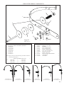
WIRE GUIDE SPRING COMPONENTS
7
6
1
8
3
5
2
12
4
11
Figure 22
10
9
(SK883 Scene 5)
ITEM PART NO.
1
a
b
c
d
e
f
g
h
DESCRIPTION
QTY
See Figures 20 WIRE GUIDE SPRING ASSEMBLY
CAAA2133W
CAAA2133L4
CAAA2133B2
CAAA2133L5
CAAA2133R2
CTTT2133A2
CTTT2133C2
CTTT2133D2
ITEM PART NO.
1
NOTE: Most of the above Wire Guide Spring Assemblies include the
following parts through 12:
a,b,d
c
e
WIRE GUIDE SPRING SUB. ASSY.
CAA2133W
f
CTT2133A2
CAA2133B2
g
CTT2133C2
CAA2133R2
h
CTT2133D2
CAAA2133W, L4, L5
(CAAA2133W View A)
CAAA2133R2
(CAAA2133W View A)
2
3
4
5
6
7
8
9
10
11
12
CB651E
CA9651
CA9652
CA9653
CA9032C
CB860B
CA9065A
CA172
CA9103C
CA9124
CA9066A
DESCRIPTION
QTY
SCREW, 10-32 x 2.000
WASHER
FELT WASHER, THICK
FELT WASHER, THIN
SPRING, COMPRESSION
NUT, 10-32, ELASTIC STOP
ROLLER, ECCENTRIC
SCREW, NYLON TIP
ROLLER, WIRE STRAIGHTENER
CLIP, ROLLER
ECCENTRIC
1
2
1
1
1
1
1
1
2
2
1
1
CTTT2133A2
(CTTT2133A2 Layout 2)
CTTT2133D2
(CTTT2133D2 Layout 2)
CTTT2133C2
(CTTT2133C2 Layout 2)
CAAA2133B2
(CAAA2133B2 Layout 2)
27
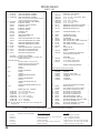
CONTENTS
INTRODUCTION
Section 1
1. Model and Serial Number
2. Product Specifications
Section
2
SAFETY PRECAUTIONS
AND PROCEDURES
3. Safety
3. Safety Guards/Cover
Section 3
4.
4.
4.
4.
5.
6.
ASSEMBLIES,
LUBRICATION,
INSTALLATION
Before Unpacking
After Unpacking
Assembly
Threading wire and adjusting wire
straighteners
Lubrication-Felt Pads
Lubrication-Stitcher Head
Section 4
OPERATION
7. General Stitching
7. Changing Work Thickness
USE ONLY REPLACEMENT
PARTS DESIGNED AND
MANUFACTURED BY ISP
SPECIFICALLY FOR YOUR
M2000 STITCHER
28
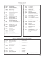
Section
8.
8.
8.
8.
8.
9.
12.
12.
13.
13.
14.
14.
15.
15.
16.
17.
17.
17.
18.
19.
19.
20.
5
MAINTENANCE, TROUBLE
SHOOTING AND
ADJUSTMENT
General
Recommended Spare Parts
Cleaning and oiling
Stitching Adjustments
To Equalize Both Legs of Stitch
Trouble Shooting-M2000 Head
Insufficient or Excessive Compression
Clincher
Head/Clincher Alignment
Bender bar
Bender bar Friction Plug
Driver Bar
Bender Bar Latch
Grip, Grip Release Slide and Faceplate
Wire Cutters
Wire cutter Operating Slide
Proper Wire
Rotator
Wire Straighteners
Supporter
Tension Pawl
Dismantling M2000 Head
Section 6
PARTS LIST
22. M2000 Head Stitcher
NOTES
29
WHEN ORDERING PARTS, PLEASE STATE: QUANTITY REQUIRED, PART
NUMBER, PART NAME, WIRE SIZE AND CROWN WIDTH OF YOUR STITCHER.
DELUXE STITCHER
COMPANY INC.
ISP Stitching & Bindery Products
3747 N. Acorn Lane, Franklin Park, IL 60131
Phone: 847-455-4400
800-634-0810
Fax: 847-455-4900
800-417-9251
http://www.deluxestitcher.com
QF76P
0613
FORM
QF76P 022013