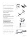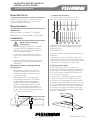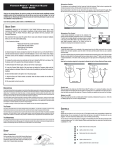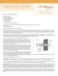
1
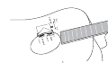
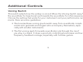
USER GUIDE
MATRIX INFINITY™
Welcome
Thank you for making Fishman a part of your acoustic experience. We are proud
to offer the finest acoustic amplification products available; high-quality
professional-grade tools which empower you to sound your very best.
3
Controls
Plug In • Connect the Matrix Infinity to your amplifier or PA with a ¼-inch
instrument cable. To conserve battery life, remove the instrument cable from the
guitar when the system is not in use.
Volume • For the cleanest noise-free sound, set the volume as high as possible
without causing your amp or mixer to distort.
Tone • This innovative one-knob tone control lets you choose between a natural,
undersaddle sound with no EQ (flat) on up to a “Scooped” tone with emphasized treble and bass and reduced midrange.
• To make individual notes sound thicker and punchier, roll the Tone
control to the right.
• Try the Tone control in the middle position for fingerpicking, when you
need just a bit of midrange cut.
• Roll the Tone control all the way to the left for more depth and
clarity to your sound, especially for hard strumming.
4
Bass
t
Boos
ing
Voic
Flat
e
ne
lat o
FT
ped
Ton
Scoo
me
er
Loud
Volu
5
Additional Controls
Voicing Switch
This switch selects how the pickup is voiced. Move the Voicing Switch away from
the soundhole for bass boost and towards the soundhole for a flat response.
Choose the setting that works for your instrument and your performance requirements. Here are some guidelines:
• The boosted bass voicing (push switch away from soundhole) compliments solo guitarists and singers who accompany themselves, especially with smaller instruments.
• The flat voicing (switch towards soundhole) cuts through the mix if
you play in a band. It does a good job controlling boominess and low
frequency feedback onstage, especially with full-size guitars.
6
Battery Replacement
A low battery LED is built into the preamp housing mounted inside the guitar.
When the Battery LED lights steadily, it is time to change the battery. To replace
the battery, remove the fabric battery bag that is mounted inside the guitar.
If you ship your guitar, we recommend you remove the battery as a precaution.
Although unlikely, it is possible for the battery to jar loose inside the instrument
during shipment.
Troubleshooting
Installation by a qualified professional is strongly recommended.
Should you have any problems, please check with your installer or refer to the
online installation guide for this product. Technical support, troubleshooting tips
and installation information can be found at http://www.fishman.com/support/
7
www.fishman.com
Fishman and Fishman Transducers are trademarks or tradenames of Fishman Transducers Inc. 513-300-132 Rev A 12-07
MATRIX INFINITY
PREAMP INSTALLATION GUIDE
www.fishman.com
Read Me First!
5. Open the preamp body by unscrewing the single
screw on the side opposite the Matrix Infinty logo.
Flip the preamp over so the circuit board remains in
the plastic housing (figure 2).
Installation of this product is a straightforward
procedure, but we recommend this job only if you
are an experienced repair technician.
6. Fasten the pickup wires to the terminal block on
the preamp module. The signal wire goes to the terminal marked “IN” and the shield wire goes to the
“GND” terminal. Tighten the screws on the terminal
block to secure the wires. Do not shorten the pickup
wire.
Requirements
Saddle Slot:
Minimum saddle slot length: 2.775” (70.48mm)
Maximum E to E string spacing at saddle: 2.5”
(63.5mm)
7. Replace the preamp’s back cover being sure the
wires do not get pinched by any plastic parts. The
housing should easily fasten tightly when the screw
is replaced.
Wide Format Width: .125” (3.17mm)
Narrow Format Width: .094” (2.39mm)
8. Secure the wires inside the instrument with the
supplied adhesive-backed clips (figure 1). Clean the
bare wood surface where you will fasten the clips.
Use an alcohol wipe or a cotton swab moistened
with rubbing alcohol.
Preliminary
1. Widen the endpin hole to 15⁄32” (11.9mm) to
accommodate the endpin jack.
2. Drill a 3⁄32” hole (2.4mm) in the saddle slot for the
pickup wire, no less than .100” (2.5mm) from nearest
string.
Standard Installation
For nylon string instruments or installation without the control module, refer to the Installation
Options below prior to mounting the Volume &
Tone controls.
1. Test the area where you will mount the Volume
& Tone control module. Locate the module flush
with the edge of the soundhole, on the bass side,
between the transverse brace and the bass-side
x-brace (figure 1).
2. Remove any lacquer and/or buffing compound
from this area using fine grit sandpaper. Clean this
surface with an alcohol wipe or a cotton swab moistened with rubbing alcohol. Let dry.
Note: For the strongest bond we recommend that
you now apply a water-based primer/sealer to the
bare wood inside the soundhole. Let the primer/
sealer dry before continuing.
Figure 1.
3. Peel back the release film on the bottom of the
preamp module and fasten the preamp to the
underside of the soundhole. Apply even, steady
pressure to the module to set the adhesive. The
adhesive gains maximum hold after 24 hours.
4. Install the pickup per Acoustic Matrix Installation
Instructions.
Figure 2.
1
Battery Bag
Install the battery bag on or near the neck block as
shown in figure 1.
1. Clean the area where you will mount the bag with
an alcohol wipe or cotton swab moistened with rubbing alcohol. Let dry.
2. Peel off the plastic film from the Velcro patch and
attach the bag at the chosen location.
3. Carefully separate the bag from the Velcro patch.
To set the adhesive, burnish the entire area of the
patch, especially the edges.
Figure 3.
4. Install a 9V alkaline or lithium battery. Tuck the
battery into the bag and re-attach to the Velcro
patch. The adhesive under the Velcro patch requires
24 hours to achieve a full bond, so take care to not
stress the adhesive if you remove the battery bag
after the initial installation.
Installation Options
Nylon String Guitar Mount
An optional control module mount is provided in
the package for use with nylon string guitars whose
bracing patterns may interfere with the standard
mount. To install this:
Figure 4.
1. Carefully push back the retaining latch and rock
the control module circuit board away from the plastic mount as shown in figure 3.
2. Locate the included nylon string guitar mount and
snap it into place as shown in figure 4.
Bass
Installation Without Controls
Under normal installations, the Volume and Tone
control module is installed in the soundhole. Optionally, the infinity preamp may be installed without
these controls, however this requires setting the
circuit board-mounted switches appropriately as
shown in figure 5.
Flat
With Volume & Tone
controls installed
If controls are removed:
1. Set switch 2 to ON
1. To remove the control module, open the Infinity
preamp case and gently pull the control module
cable and connector away from its circuit boardmounted connector.
2. Choose Flat voicing or
Figure 5.
Bass Boost with switch 1.
2. Use switch marked with a “1” to select either a
bass boost (“ON” position) or the flat setting.
3. Set the switch marked with a “2” to the “ON”
position. This allows the preamp to operate properly
without the control module in place.
Second Pickup Source Option
A second source such as a microphone or magnetic
soundhole pickup may be added (figure 6). The
output will appear on the ring connection when a
tip-ring-sleeve 1/4” jack is inserted.
Figure 6.
For specific wiring diagrams, refer to fishman.com.
2
514-300-003 Rev B 5-08
ACOUSTIC MATRIX PICKUP
INSTALLATION GUIDE
www.fishman.com
Read Me First!
1. Locate the wire hole
Installation of this product is a simple procedure,
but we recommend this job only if you are an
experienced repair technician.
1. Locate the center of the wire hole no less
than .100” (2.5mm) from the closest string.
Requirements
Saddle slot
No less than .100” (2.54mm)
Minimum saddle slot length: 2.775” (70.4mm)
Maximum E to E spacing at saddle: 2.5” (63.5mm)
Installation
Observe the following
precautions!
• Handle the pickup carefully! Do not trim the
pickup to make it fit. Mishandling may tear
the delicate foil shield, producing ground
hum or intermittent signal.
3. Drill a .094” hole.
4. Clear wood chips and foreign materials from the
saddle slot.
• Do not shorten the pickup wire. This will
result in poor pickup performance and loss
of bass.
• Both the saddle and saddle slot must be flat
and square for proper pickup performance
and balance.
5. Carefully insert (do not bend) the pickup. The
pickup must fit loosely in the slot, without binding.
If the corners of the pickup touch the radiused ends
of the saddle slot, pickup failure could result.
2. Prepare the saddle
Mechanical factors affecting pickup
performance
Organic saddles (eg, bone or ivory) are not
structurally as consistent as synthetic materials and
may not produce optimal string balance through
the pickup. Synthetic materials such as Micarta™
or Corian™ are suggested.
• Break Angle: In order for the pickup to
perform optimally, there should be a 20°
(minimum) string break angle across the
back of the saddle.
• The 50/50 Rule: There is an important
relationship between the overall saddle
height and the bridge slot depth. We
suggest that the saddle slot depth (with
pickup installed) measures no more than
50% of the total height of the saddle. If
the slot measures more than 50% the total
height of the saddle, balance and/or output
level of the pickup may suffer.
P
2. Mark the location where the wire will enter the
saddle slot. Center the mark between the walls
(width) of the slot.
1. Prepare a .125” wide saddle (.094” for Narrow
Format). The bottom of the saddle must be flat.
2. Remove only enough material from the width of
the saddle to provide a sliding fit in the slot. To test
the fit, the saddle should slide easily in the slot, but
should not fall out when overturned. To maintain
your current action, the new saddle must be .053”
shorter in height (.043” for Narrow Format pickups)
than your current saddle.
NO MORE THAN 50%
M
RA
www.fishman.com
514-300-108 Rev A 5-09