1
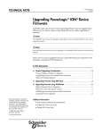
PowerLogic™ ION™ Setup 3.0
Meter configuration software
User guide
7EN02-0312-00
03/2012
Contents
Safety information
7
Chapter 1: Safety precautions
9
Chapter 2: Introduction
11
ION Setup features
Your first installation (Network Builder Wizard)
System requirements
Overview
Assumptions
Where to learn more
Getting more information
Installing ION Setup
Communicating with devices
Using serial communications
Using modem communications
Using Ethernet communications
Using Ethernet Gateways or Modbus gateways
List of common procedures
Chapter 3: Configuring ION Setup
12
12
13
13
13
13
14
14
15
15
17
18
19
21
23
Starting, logging on and logging off
Starting ION Setup
Logging off or shutting down ION Setup
Starting your first installation (Network Builder wizard)
Creating your first installation
Using the Network Viewer
ION Setup commands
Viewing options
View modes
Viewing by site, group or both
Basic versus Advanced Mode
Setting up options
Before you begin
Applying security
Chapter 4: Adding and configuring devices
24
24
27
27
28
31
33
35
35
36
37
38
38
43
47
Single Device mode and Network mode
Working in Single Device mode
Using serial communications
Using modem communications
Using Ethernet communications
Using offline programming
Working in Network mode
Setting up a network in ION Setup
Adding and configuring sites
Adding a new device
Grouping devices
Assigning a device to a group
Removing items from the network
Editing site properties
48
50
51
51
52
52
54
56
56
60
60
61
61
62
Editing group properties
Editing meter properties
Working in Basic Configuration mode
Editing in Basic Configuration mode
Setup screen examples
Errors
Typical meter setup parameters
Working in Advanced Configuration mode
Synchronizing the time across devices
ION meter cloning
Chapter 5: Using the Setup Assistant
64
64
66
67
68
71
71
72
78
78
81
Setup Assistant overview
Available Setup Assistant screens
Template screen
Basic Setup screen
Security screen
Communications screens
3rd Party Protocols screen
Clock screen
Demand screen
Input / Output screens
LED Pulsing screen
Energy Pulsing screen
Onboard Digital Inputs screen
Onboard Digital Outputs screen
Expansion Analog Inputs screen
Expansion Analog Outputs screen
Expansion Digital Inputs screen
Analog Outputs screen
Memory screen
Load Profile/Revenue Log screen
Event Log screen
EnergyDemand Log screen
PT/CT Correction screen
Transformer Loss screen
Time of Use (TOU) screen
Alarming screen
Power Quality screen
Displays screen
Verification screen
Reports screen
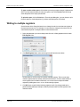
Writing to multiple registers
Chapter 6: Monitoring your network
82
83
84
86
88
94
94
96
98
99
99
100
101
102
103
104
104
105
106
106
107
108
110
110
112
116
117
118
121
125
128
129
Displaying data
Performing control operations
Manually operating triggers
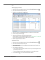
Chart plotting
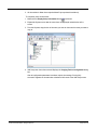
Displaying Event Log reports in Microsoft Excel
Chapter 7: Troubleshooting
130
132
132
132
135
137
Troubleshooting ION Setup
138
Troubleshooting devices
ION Setup diagnostics tools
Communication tab
General tab
Accessing the Modbus Tester Interface tool
Index
138
138
139
141
141
143
Safety information
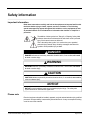
Important information
Read these instructions carefully and look at the equipment to become familiar with
the device before trying to install, operate, service or maintain it. The following
special messages may appear throughout this bulletin or on the equipment to warn
of potential hazards or to call attention to information that clarifies or simplifies a
procedure.
The addition of either symbol to a "Danger" or "Warning" safety label
indicates that an electrical hazard exists which will result in personal
injury if the instructions are not followed.
This is the safety alert symbol. It is used to alert you to potential
personal injury hazards. Obey all safety messages that follow this
symbol to avoid possible injury or death.
DANGER
DANGER indicates an imminently hazardous situation which, if not avoided, will result
in death or serious injury.
WARNING
WARNING indicates a potentially hazardous situation which, if not avoided, can result
in death or serious injury.
CAUTION
CAUTION indicates a potentially hazardous situation which, if not avoided, can result in
minor or moderate injury.
NOTICE
NOTICE is used to address practices not related to physical injury. The safety alert
symbol shall not be used with this signal word.
Please note
Electrical equipment should be installed, operated, serviced and maintained only by qualified
personnel. No responsibility is assumed by Schneider Electric for any consequences arising
out of the use of this material.
© 2012 Schneider Electric. All rights reserved.
Page 7 of 147
Safety information
ION Setup 3.0 Device configuration guide
A qualified person is one who has skills and knowledge related to the construction,
installation, and operation of electrical equipment and has received safety training to
recognize and avoid the hazards involved.
Page 8
© 2012 Schneider Electric. All rights reserved.
Chapter 1: Safety precautions
Installation, wiring, testing and service must be performed in accordance with all local and
national electrical codes.
DANGER
HAZARD OF ELECTRICAL SHOCK, EXPLOSION OR ARC FLASH
• Apply appropriate personal protective equipment (PPE) and follow safe electrical work
practices. See NFPA 70E in the USA or applicable local standards.
• Electrical equipment must only be installed and serviced by qualified electrical
personnel.
• Turn of all power supplying a device and the equipment in which it is installed before
working on the device or equipment.
• Always use a properly rated voltage sensing device to confirm that all power is off.
• Replace all devices, doors and covers before turning on power to this equipment.
Failure to follow these instructions will result in death or serious injury.
WARNING
UNINTENDED EQUIPMENT OPERATION
Do not use ION Setup and associated devices for critical control or protection
applications where human or equipment safety relies on the operation of the control
circuit.
Failure to follow these instructions can result in death or serious injury.
WARNING
INACCURATE DATA RESULTS
• Do not incorrectly configure ION Setup and its associated devices; this can lead to
incorrect reports and/or data results.
• Do not rely solely on reports or data results to determine if ION Setup and its
associated devices are functioning correctly or meeting all applicable standards and
compliances.
• Do not use reports or data results as substitutes for proper workplace practices or
equipment maintenance; they are supplemental only.
© 2012 Schneider Electric. All rights reserved.
Page 9 of 147
Chapter 1: Safety precautions
ION Setup 3.0 Device configuration guide
Failure to follow these instructions can result in death or serious injury.
Page 10
© 2012 Schneider Electric. All rights reserved.
Chapter 2: Introduction
PowerLogic™ ION™ Setup is a user-friendly configuration tool that provides an intuitive
environment for setting up and verifying settings on PowerLogic meters and other devices.
Devices can be configured over communications links whether they are locally or remotely
located. Hard drive footprint and memory requirements for ION Setup are minimal, so it is
easy to install and use.
Typically, you can perform basic setup through the meter’s front panel or remote display.
ION Setup is mainly used for configuring advanced features of the device, or for setting up a
device that does not have a front panel or remote display.
In this section
ION Setup features
12
Your first installation (Network Builder Wizard)
12
System requirements
13
Overview
13
Assumptions
13
Where to learn more
13
Getting more information
14
Installing ION Setup
14
Communicating with devices
15
Using serial communications
15
Using modem communications
17
Using Ethernet communications
18
Using Ethernet Gateways or Modbus gateways
19
List of common procedures
© 2012 Schneider Electric. All rights reserved.
21
Page 11 of 147
Chapter 2: Introduction
ION Setup 3.0 Device configuration guide
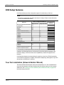
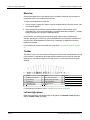
ION Setup features
ION Setup software provides configuration support for a wide variety of devices.
Note
The devices supported by ION Setup are subject to change. Please contact Schneider
Electric for the latest information.
Devices
Branch Circuit Power Meter (BCPM
and BCPMSC)
Enercept
E5600
ION6200
ION7300 / ION7330 / ION7350
ION7550 / ION7650 / ION7550 RTU
ION8600
ION8650
ION8800
PM5350
PM700 series
PM800 series
Basic Configuration Method
Setup Screens
Real-time Data
Display
Setup Assistant
yes1
yes1
yes1
yes1
yes
yes
yes
yes
yes
yes
yes
yes
yes
yes
yes
yes
yes
yes
yes1
yes1
Legacy Devices
3000 series
yes
yes
ION6300
yes
ION7700
yes
yes
ION7500 / ION7600 / ION7500 RTU
yes
yes
ION8300 / ION8400 / ION8500
yes
yes
1 For instructions on configuring these devices, refer to the ION Setup Device Configuration Guide.
In addition, ION Setup provides an environment for historical trending, disturbance and
harmonics display, as well as remote control capabilities (if the device supports those
features).
ION Setup also features on-screen plotting of waveforms, time of use (TOU) functionality,
communications diagnostics, template customization and pasting, and support for up to 255
sites with up to 128 devices in each site.
Your first installation (Network Builder Wizard)
The Network Builder Wizard opens the first time ION Setup is run. This wizard allows the
user to quickly and easily set up and configure their first system made up of sites, groups,
and devices. See "Starting your first installation (Network Builder wizard)" on page 27 to
learn about using the wizard.
Page 12
© 2012 Schneider Electric. All rights reserved.
System requirements
• Microsoft Windows 7 (32- and 64-bit versions), Windows Vista, Windows XP, or
Windows 2000
• Mouse or pointing device
• VGA display
• 1 gigahertz (GHz) or faster 32-bit (x86) processor
• 1 gigabyte (GB) RAM (32-bit) or more
• 100 MB available hard-drive space or more
• DirectX 9 graphics device with WDDM 1.0 or higher driver
Overview
This ION Setup User guide is designed to introduce you to ION Setup software to quickly get
your system up and running.
You should use this guide:
• To learn about the main features of ION Setup.
• To view the main windows of ION Setup and find out how each is used.
• To read an overview of the ION Setup workflow and tasks.
Assumptions
This guide assumes that:
• You have a working knowledge of electrical systems.
• You are familiar with your Windows operating systems and the devices in your system.
• You have a working knowledge of networked environments, including client/server
systems.
• You have read and you understand the installation, basic setup and all other procedures
and warnings in the documentation for the devices in your system.
• All hardware, software, and network components of your computer system have been
installed and configured according to their instructions, and they are operating correctly.
Where to learn more
This section describes additional resources for learning ION Setup.
Online help
The ION Setup online help is your primary source of information. Use the online help to:
• Read step-by-step procedures for all ION Setup tasks.
• Find out how the options in any ION Setup window will affect your software.
© 2012 Schneider Electric. All rights reserved.
Page 13 of 147
Chapter 2: Introduction
ION Setup 3.0 Device configuration guide
• Search for information about a topic or keyword.
To access online help
• Select Help > Contents from the menu in any ION Setup window, or click
in the
toolbar or the help button in any dialog box to display help information.
To search for a topic in the online help index: 1. Click the Search tab on the left side of the help index window.
2. In the box at the top of the Search tab, type a keyword and click List Topics.
3. Double-click on a topic to display it, or select the topic and click Display. The topic is
displayed and the search word or phrase is highlighted.
Home page
In ION Setup, select Help > Visit Home Page to access the following information:
• Technical Support
• News
• ION Setup Home
• Documentation
• FAQs
• Downloads
Getting more information
Documentation for other Schneider Electric products is available at www.schneiderelectric.com.
Installing ION Setup
To install ION Setup, download the IONSetup.exe file from www.schneider-electric.com.
Double-click the IONSetup.exe file to begin installing onto your local workstation.
Upgrading from previous versions of ION Setup
When upgrading ION Setup, the installer asks if you want to overwrite your existing default
Setup Assistant configuration:
• Select Yes to make use of the upgraded functionality of the Setup Assistants.
Any custom Setup Assistants that were created (separate from the default Setup
Assistant) will then remain after upgrading.
• Select No if the default Setup Assistant files were customized and you want to retain
those files after upgrading.
Page 14
© 2012 Schneider Electric. All rights reserved.
Note
To uninstall ION Setup, double-click IONSetup.exe, select Remove, and click Next.
Select Yes when prompted to completely remove the application and all of its features.
Navigate to the location where ION Setup was installed to verify that all ION Setup files
have been removed.
Communicating with devices
ION Setup uses one or more ports to communicate with the devices at each site in the
system. Each port of the workstation running ION Setup can connect to one or more remote
sites using a variety of communications hardware options. The next sections discuss
general considerations when using different communications hardware options, including:
• Serial communications:
• direct connection to a single device using RS-232
• direct connection to multiple devices using RS-485
• direct connection to a single device using an optical probe
• Ethernet and Ethernet gateway communications
• Modem communications to remote sites (through telephone lines, radio links, fibre optic
cables, microwave links, etc.).
For detailed information on configuring devices with these communications options, see
"Adding and configuring devices" on page 47. For details on configuring devices using offline
programming, see "Using offline programming" on page 52.
Using serial communications
ION Setup supports the RS-485 and RS-232 communications standards. If the device is
equipped with an RS-232 port, you can use an RS-232 cable to directly connect the device to
an available serial port on the computer.
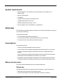
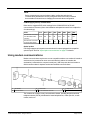
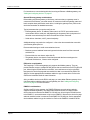
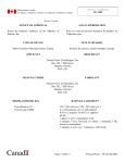
To connect to more than one serial device, you can use an RS-232 to RS-485
communications converter. The RS-232 port on the converter connects to the computer’s
serial port, and the RS-485 port connects to up to 32 RS-485 devices.
A
Workstation
© 2012 Schneider Electric. All rights reserved.
B
RS-232 to RS-485 converter
C RS-485 devices (maximum 32)
Page 15 of 147
Chapter 2: Introduction
ION Setup 3.0 Device configuration guide
Make sure the serial communications parameters are set correctly for each device (for
example, protocol, baud rate, parity and unique device address/unit ID). For serial
communications at 9600 baud, ION Setup polls at roughly one device per second.
For instructions on communicating with serial devices, see "Adding and configuring devices"
on page 47.
Connecting to serial devices
If you want to connect your computer to a single meter, you can use either RS-232 or RS485:
• If the computer is less than 50 ft (15 m) from the meter, use either RS-232 or RS-485.
• If the computer is more than 50 ft (15 m) from the meter, but less than 4000 ft (1200 m),
use RS-485.
To connect your workstation to more than one meter, you must use RS-485. In this case, you
need either:
• an RS-485 communications port on the computer, OR
• an RS-232 communications port and an RS-232 to RS-485 converter. Communications
converters such as the COM32 or COM128 (legacy products) can support up to 32 and
128 devices, respectively.
NOTICE
EQUIPMENT DAMAGE
Do not connect the RS-232 terminals with the RS-485 terminals of any device.
Failure to follow these instructions can result in equipment damage.
Directly connecting a single device using RS-232
Use a suitable RS-232 cable to connect your workstation directly to a single ION meter. Both
the workstation and the meter must have RS-232 communications ports. With a direct RS232 link, only one meter can be connected to each serial port of the workstation. Refer to the
meter’s installation manual for details on RS-232 communications connections.
Directly connecting multiple devices using RS-485
An RS-485 communications link allows you to connect your workstation to up to thirty-two
devices using shielded twisted-pair wire. If your workstation is not equipped with an internal
RS-485 communications card, you can connect an external RS-232 to RS-485 converter to
the computer’s RS-232 serial port.
Page 16
© 2012 Schneider Electric. All rights reserved.
Note
Before connecting any communications cables, confirm that each device's
communication port has been correctly configured. Refer to the meter’s technical
documentation for instructions on changing the communications configuration.
COM128 (legacy device) considerations
Below are the suggested DIP switch settings for the COM128 RS-232 to RS-485
communications converter (refer to the installation and operation manual for a complete list
of mode settings):
Mode
Port
Baud
SW1
SW2
SW3
SW4
SW5
SW6
RS-485 Flow Control with
Auto Baud Rate Detect
(Modem)
DCE
N/A
OFF
ON
OFF
ON
ON
OFF
RS-485 Flow Control with
Hardware RTS (Serial)
DCE
N/A
ON
OFF
ON
ON
ON
OFF
Optical probes
ION Setup supports optical probe communications for meters equipped with compatible
optical IR ports. Refer to "Optical probe communications" on page 51 for details.
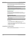
Using modem communications
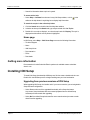
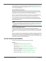
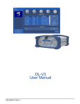
Modem communications requires two or more compatible modems: one modem is located at
each remote site (connected to one or more serial devices) and one is located at the
workstation (connected to the computer’s serial port). ION Setup uses the local modem to
dial the remote modems' telephone number and establish communications.
A
D
Workstation
Remote modem
B
E
Local modem
RS-232 to RS-485 converter
C
F
Telephone line
RS-485 devices
The modems can connect via any communication channel, including the public switched
telephone network (PSTN), a dedicated or leased telephone line, a fiber-optic link, a radio
modem, and so on.
© 2012 Schneider Electric. All rights reserved.
Page 17 of 147
Chapter 2: Introduction
ION Setup 3.0 Device configuration guide
Each remote site may contain one or more meters, with appropriate communication
connections (RS-485 for multiple devices at a single site and RS-485 or RS-232 for a single
device). Any site using an RS-485 communication link also requires an RS-232 to RS-485
converter to connect to the modem.
Note
RS-232 permits only one device to be connected to a modem. Use an RS-232 to RS-485
converter if more than one device will be installed at the remote site.
For instructions on communicating with devices using modem communications, see "Adding
and configuring devices" on page 47.
ModemGate feature
Some ION meters are equipped with an internal modem that you can set up as a
communications gateway to connect to multiple RS-485 devices (e.g., on a remote site). For
more information, refer to the technical note The ION meter as a ModemGate available at
www.schneider-electric.com.
Manually operating modems
Note
To stop modem communications (for example, if the remote modem is not responding),
press the ESC key on your keyboard. When you do this, ION Setup attempts to stop
modem communication.
ION Setup automatically dials a modem site when you view information from a meter at that
site, but it does not automatically disconnect until requested to do so. To manually control a
modem connection:
1. Select Tools > Modem Control (or click
on the toolbar). All the sites that are
currently connected via modem are listed in the Modem Sites dialog box.
2. To connect to a site, select the site you want to connect to and click Dial. (If this button is
unavailable, it means the modem site is already connected. To terminate a connection and
hang up the modem, click Hang Up.
3. Click Close to close the dialog box.
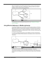
Using Ethernet communications
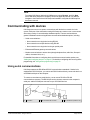
If the device is equipped with Ethernet communications, you can use an Ethernet cable to
connect it to your local or wide area network (LAN/WAN).
Page 18
© 2012 Schneider Electric. All rights reserved.
Make sure the Ethernet communications parameters are set correctly for each device (for
example, IP address, subnet mask, default gateway, media type). Refer to your device’s
installation manual for details on Ethernet connections.
A
LAN / WAN
B
Ethernet devices
For instructions on communicating with Ethernet devices, see "Adding and configuring
devices" on page 47.
Using Ethernet Gateways or Modbus gateways
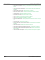
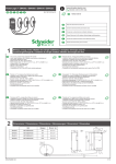
Some Ethernet-capable devices can also serve as communications gateways. An Ethernet
gateway device provides a communications link between its Ethernet port and its serial port.
The gateway device receives TCP data on its Ethernet port, converts the data to RTU and
sends the converted data to its serial port(s) and vice versa. This allows communication with
the serial devices over Ethernet.
For example, a Modbus Ethernet gateway receives Modbus TCP data on its Ethernet port,
converts the data to Modbus RTU and sends the converted data to devices connected to its
serial port(s).
A
LAN / WAN
B
Ethernet
D
Serial RS-485
E
RS-485 devices
C Ethernet gateway device
Some devices can function as both metering points and gateways. This type of
communications topology is typically used in applications where you have a high-end meter
monitoring the incoming supply at the service entrance and mid-range meters monitoring the
feeders.
© 2012 Schneider Electric. All rights reserved.
Page 19 of 147
Chapter 2: Introduction
ION Setup 3.0 Device configuration guide
For instructions on communicating with devices using an Ethernet or Modbus gateway, see
"Adding and configuring devices" on page 47.
General Ethernet gateway considerations
Before adding an Ethernet gateway to ION Setup, make sure that your gateway meter is
connected to the Ethernet, your serial network of meters are wired to the gateway meter and
basic setup has been performed on each device, including the gateway meter). Refer to the
device documentation for detailed instructions.
Typical parameters that you need to configure are:
• Ethernet gateway device: IP address, subnet mask, the TCP/IP port number used to
communicate with the serial port, and (depending on the gateway device) the protocol of
the serial communications port to which the serial devices are connected.
• Serial devices: baud rate, unit ID, protocol and parity.
Additional settings may need to be configured — refer to the documentation that came with
your Ethernet gateway device.
Recommended settings to avoid communications issues:
• Baud rate, protocol and data format settings need to be the same for all the connected
serial devices.
• Each serial device must have a unique Unit ID.
• The gateway device must have the same baud rate and data format settings as the
connected serial devices, if these can be configured.
EGX series considerations
The PowerLogic™ EGX series gateway only supports the Modbus gateway. They can
provide Ethernet access to multiple RS-485 devices that are connected to the EGX’s RS-485
port. After wiring the RS-485 devices to the EGX, use a web browser to log in to the EGX.
Navigate to the device list page and enter each device that is connected to the EGX’s RS485 port. Set the appropriate device address and device type for each device. Refer to the
EGX Series Installation Guide for more information.
After you add the devices to the EGX’s web page, you must add an Ethernet gateway site to
ION Setup and then add those devices to the gateway site. See "Adding and configuring
devices" on page 47 for more information.
PM8ECC considerations
Similar to the EGX series gateway, the PM8ECCEthernet communications card only
supports the Modbus gateway. The card provides Ethernet access to multiple RS-485
devices that are connected to the PM8ECC’s RS-485 port. After wiring the RS-485 devices
to the PM8ECC, use a web browser to log in to the PM8ECC. Browse to the device list page
and enter each device that is connected to the PM8ECC’s RS-485 port. Set the appropriate
device address and device type for each device. Refer to the PM8ECC Installation Guide.
Page 20
© 2012 Schneider Electric. All rights reserved.
After you add the devices to the web page, you must add an Ethernet gateway site to ION
Setup and then add those devices to the gateway site. See "Adding and configuring devices"
on page 47 for more information.
ION meter EtherGate considerations
When an Ethernet-capable ION meter has EtherGate enabled, a workstation using ION
Setup software can communicate through the meter to a serial device (or devices) wired to
the appropriate serial communications port of the EtherGate-enabled meter.
When you configure the EtherGate-enabled meter (in addition to the general settings listed
above), the protocol for the serial communications port must be set to EtherGate.
For more information on using your meter as an EtherGate, refer to the gateway meter’s
documentation and the technical note The ION Meter as an Ethernet Gateway available at
www.schneider-electric.com.
Note
To connect to and read data from your EtherGate meter, in addition to the serial devices,
add the meter as a stand-alone Ethernet meter in ION Setup. See "Adding a new device"
on page 60.
ION7550 / ION7650 Modbus gateway ION7550 / ION7650 meters (firmware v350 or later) also support Modbus gateway
communications. This allows you to use the meter to provide Modbus RTU communications
support for up to 16 downstream Modbus RTU devices on the same serial communications
loop.
When you configure the meter as a Modbus gateway (in addition to the general settings listed
above), the protocol for the serial communications port must be set to Modbus Master. You
do not need to set the TCP/IP port; for Modbus TCP communications, the Ethernet IP port is
hard-coded to port 502 on ION7550/ION7650 meters.
List of common procedures
This section lists procedures commonly performed in ION Setup:
How do I...?
• Add a new meter: "Adding a new device" on page 60
• Add a new site: "Adding and configuring sites" on page 56
• Apply TOU profiles: "Time of Use (TOU) screen" on page 112
• Assign a device to a group: "Assigning a device to a group" on page 61
• Clone a meter configuration: "ION meter cloning" on page 78
• Configure interval/depth: "Configuring Interval/Depth" on page 109
• Create new ION modules: "Creating new ION modules " on page 75
© 2012 Schneider Electric. All rights reserved.
Page 21 of 147
Chapter 2: Introduction
ION Setup 3.0 Device configuration guide
• Create your first installation: "Starting your first installation (Network Builder wizard)" on
page 27
• Create or edit custom register labels: "Customizing ION module output register labels"
on page 78
• Create or modify user accounts: "Applying security" on page 43
• Delete links between modules: "Deleting links between ION modules" on page 77
• Edit site properties: "Editing site properties" on page 62
• Find exceptions to cloning: "ION meter cloning" on page 78
• Log off: "Logging off or shutting down ION Setup" on page 27
• Log on: "Starting, logging on and logging off" on page 24
• Open multiple data screens: "Opening multiple data screens at the same time " on page
131
• Plot historical data: "Chart plotting" on page 132
• Remove a group, site, or device from the network: "Removing items from the network"
on page 61
• Select output registers: "Editing meter properties" on page 64
• Switch between setup screen and data screen views: "Viewing options" on page 35
• Switch between basic and advanced configuration modes: "Basic versus Advanced
Mode" on page 37
• View ION module output registers: "Viewing ION module output registers" on page 78
Page 22
© 2012 Schneider Electric. All rights reserved.
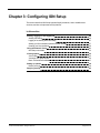
Chapter 3: Configuring ION Setup
This section describes ION Setup logon and logoff procedures, how to establish user
accounts, and how to implement security features.
In this section
Starting, logging on and logging off
24
Starting ION Setup
24
Logging off or shutting down ION Setup
27
Starting your first installation (Network Builder wizard)
27
Creating your first installation
28
Using the Network Viewer
31
ION Setup commands
33
Viewing options
35
View modes
35
Viewing by site, group or both
36
Basic versus Advanced Mode
37
Setting up options
38
Before you begin
38
Applying security
43
© 2012 Schneider Electric. All rights reserved.
Page 23 of 147
Chapter 3: Configuring ION Setup
ION Setup 3.0 Device configuration guide
Starting, logging on and logging off
The following sections outline the initial start up of ION Setup, logon options and procedures
and how to exit and log off.
Starting ION Setup
The following sections outline the startup modes for ION Setup and the procedures for initial
and subsequent ION Setup startup.
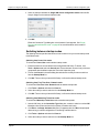
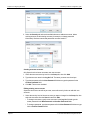
Startup and View modes
The following table outlines the ION Setup startup modes. You can configure these startup
modes by:
• Selecting the option in the User Profiler dialog box that appears when you first run an
installation of ION Setup. See "Starting your first installation (Network Builder wizard)" on
page 27.
• Selecting the option from the Startup Mode list on the View tab of the Options dialog box
(Tools > Options).
The startup mode that ION Setup is using determines the mode of operation (Network mode,
Single Device mode, or a choice) and whether or not a username and password are required.
For more information on the modes of operation, see "Single Device mode and Network
mode " on page 48.
Note
You can only configure non-default users when in Power User Mode, and you cannot
switch to other modes with non-default users configured without first deleting those
users. If you configure users while in other modes, ION Setup switches to Power User
mode.
Startup Mode
Page 24
Username /
Password
Required?
Description
Mode of
Operation
First Time User /
Network Mode
This option launches ION Setup in Network Mode. If
you select this mode the first time you launch ION
Setup, the Network Builder Wizard appears; when
you subsequently launch ION Setup, it opens in
Network Mode.
No
Network
Metershop
Technician Mode
This option launches ION Setup in Single Device
mode, displaying the Connection Type dialog box.
No
Single Device
Power User Mode
This option prompts you for a username and
password. You can choose to launch ION Setup in
Network Mode or you can select the check box to
launch in Single Device Mode.
Yes
Login dialog box
allows you to
select the view
mode.
© 2012 Schneider Electric. All rights reserved.
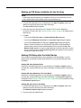
Starting an ION Setup installation for the first time
Note
If ION Setup does not appear on your Programs menu or one of its submenus, use the
Find or Search feature from the Start menu to locate IONSetup.exe.
1. Click the ION Setup shortcut on your desktop (or click Start > Programs, point to the
folder that contains ION Setup, then select ION Setup).
The User Profiler dialog box appears.
2. Select the type of user that best fits your situation: First Time User, Metershop
Technician, or Power User. See "Startup and View modes" on page 24 for a description of
these options.
3. Click OK.
• If you selected First Time User, the Network Builder Wizard appears.
• If you selected Metershop Technician, the Connection Type dialog box appears.
• If you selected Power User, the ION Setup System Log On dialog box appears.
Select or clear the checkbox to run ION Setup in single device mode (selected) or
network mode (cleared). Enter the default password of 0 (zero) and click OK. The
Network Viewer appears if you are running ION Setup in network mode and if you have
not yet created a network; the Connection Type dialog box appears if you are running
ION Setup in single device mode.
Starting ION Setup after the Initial Startup
The procedure for starting ION Setup varies depending on the Startup Mode. If you are
logging in with non-default username and password, you must start ION Setup in Power
User Mode.
Starting ION Setup (Network Mode)
Double-click the ION Setup shortcut on your desktop (or click Start > Programs, point to
the folder that contains ION Setup, then select ION Setup). ION Setup opens to the Network
Viewer.
Starting ION Setup (Metershop Technician Mode)
Double-click the ION Setup shortcut on your desktop (or click Start > Programs, point to
the folder that contains ION Setup, then select ION Setup). The Connection Type dialog
box appears. See "Working in Single Device mode" on page 50 for more information on using
the Connection Type dialog box.
Starting ION Setup (Power User Mode)
1. Click the ION Setup shortcut on your desktop (or click Start > Programs, point to the
folder that contains ION Setup, then select ION Setup).
The ION Setup System Log On dialog box appears.
2. Type your username and password.
© 2012 Schneider Electric. All rights reserved.
Page 25 of 147
Chapter 3: Configuring ION Setup
ION Setup 3.0 Device configuration guide
3. Select or clear the checkbox for Single ION device configuration mode to launch ION
Setup in Single Device mode or Network mode.
4. Click OK.
Either the Connection Type dialog box or the Network Viewer appears. See "Single
Device mode and Network mode " on page 48 for more information on the modes of
operation.
Switching between startup modes
The following sections provide instructions on how to switch from your current startup mode
to a different mode.
Switching from Power User mode
To switch from Power User mode to another startup mode:
1. Ensure that there are no non-default users configured in ION Setup. To do this, click
Tools > Options and select the Security tab. Ensure there are no users in any of the user
groups other than the default supervisor user in the Supervisor group.
2. Click on the View tab in the same dialog box and select the mode you want to switch to
from the Startup Mode list.
3. Click OK. The next time you launch ION Setup, it will use the selected startup mode.
Switching from First Time User / Network mode
To switch from First Time User / Network mode to another startup mode:
1. Click Tools > Options and select the View tab.
2. Select the mode you want to switch to from the Startup Mode list.
3. Click OK. The next time you launch ION Setup, it will use the selected startup mode.
Switching from Metershop Technician mode
To switch from Metershop Technician mode to another startup mode:
1. Launch ION Setup. In the Connection Type dialog box, connect to a device or select OffLine then select a firmware from the list (it does not matter which one).
2. Click Exit on the Setup Assistant dialog box (if it appears) then click No when prompted
about saving your offline configuration or connecting to another device.
3. Click Tools > Options and select the View tab.
4. Select the mode you want to switch to from the Startup Mode list.
Page 26
© 2012 Schneider Electric. All rights reserved.
5. Click OK. The next time you launch ION Setup, it will use the selected startup mode.
Temporarily switching to Power User mode
To temporarily switch to Power User mode from Metershop Technician or Network mode:
1. Select File > Exit. The Exit Options dialog box appears.
2. Select User Logoff and click OK. The System Log on dialog box appears.
3. Select or clear the checkbox to open ION Setup in single device mode (selected) or
network mode (cleared).
The next time you start ION Setup, it reverts back to the original mode.
Logging off or shutting down ION Setup
Logging off from ION Setup exits your session and displays the ION Setup System Log On
screen. Shutting down the program exits ION Setup completely.
To log off from or shut down ION Setup:
1. Select File > Exit.
If you have made any network configuration changes, you are prompted to save the
network configuration file (IONSetup.dat).
2. Click OK to save your changes. The next time you open ION Setup, your saved
configuration changes appear. Click No to discard your changes. The Exit Options dialog
box appears.
3. Select User Logoff or Shutdown Program, then click OK.
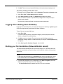
Starting your first installation (Network Builder wizard)
The Network Builder wizard opens the first time ION Setup is run. This wizard allows the
user to quickly and easily set up and configure a first installation made up of sites, groups,
and devices.
Note
If ION Setup does not appear on your Programs menu or one of its submenus, use the
Find or Search feature from the Start menu to locate the program file IONSetup.exe.
1. Click the ION Setup shortcut on your desktop (or click Start > Programs, point to the
folder that contains ION Setup, then select ION Setup).
• The User Profiler dialog box appears, and First Time User is selected.
© 2012 Schneider Electric. All rights reserved.
Page 27 of 147
Chapter 3: Configuring ION Setup
ION Setup 3.0 Device configuration guide
2. Click Next.
• The Network Builder Wizard dialog box appears.
If you are not a first-time user, see "Switching between startup modes" on page 26 for
information about changing the mode to Metershop Technician or Power User.
Creating your first installation
The following types of communications sites are available:
• Serial
• Modem
• Ethernet
Page 28
© 2012 Schneider Electric. All rights reserved.
• Ethergate or Modbus Gateway
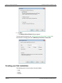
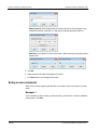
To create your first site
1. Type a site name in the Name field.
2. Select a Serial, Modem, or Ethernet Comm Link type.
3. Depending on the Comm Link type you choose, select choices from the dropdown lists or
enter necessary information in the fields for phone number, gateway information, etc..
4. Click Next.
The Network Builder Wizard dialog box appears showing the first site created.
Related topics
• "Using modem communications" on page 51
• "Using serial communications" on page 51
• "Using Ethernet communications" on page 52
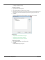
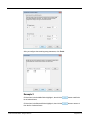
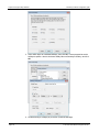
To add your first device
1. Select a Comm Link type, such as Ethernet Site.
2. Click Add.
The New Device dialog box appears.
© 2012 Schneider Electric. All rights reserved.
Page 29 of 147
Chapter 3: Configuring ION Setup
ION Setup 3.0 Device configuration guide
3. Type a name in the Name field. Note that names must begin with a letter (a-z, or A-Z).
4. Select your device from the dropdown list for Type.
5. Complete other fields as necessary.
6. Select a group name from the dropdown list for Group.
7. Click OK.
The dialog box appears showing a new device added to the site.
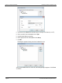
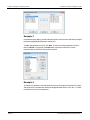
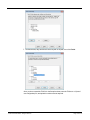
Once you have added a device to a new site, the following dialog box appears. Click Finish
to continue.
Page 30
© 2012 Schneider Electric. All rights reserved.
Related topics
• "Adding and configuring devices" on page 47
The next time you start ION Setup, the sites and devices you have added will be available in
Network Mode where you can add, remove, or configure sites and devices to continue
building your network.
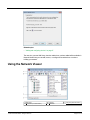
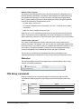
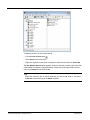
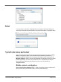
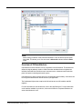
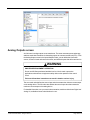
Using the Network Viewer
A
D
Menu bar
Right pane (Content Viewer)
© 2012 Schneider Electric. All rights reserved.
B
E
Tool bar
Status bar
C
Left pane (Network Viewer)
Page 31 of 147
Chapter 3: Configuring ION Setup
ION Setup 3.0 Device configuration guide
Menu bar
Selecting a heading on the menu displays a list of available commands. Use the mouse or
keyboard to select a command from the menu bar.
To select a command from the menu bar:
1. Click on a menu (or press ALT and then type the underlined letter in the menu name). A list
of commands appears.
2. Select the desired command (or type the underlined letter in the command). Some
commands carry out an action immediately; commands followed by an ellipsis (...) display
a dialog box where you can specify additional options.
In some cases, you can choose commands by typing a shortcut key combination (for
example, pressing ALT+ ENTER on your keyboard activates the Properties command from
the Item menu). When available, the shortcut key combination is displayed on the menu
beside the command.
For a complete list of menu commands, refer to the topic "ION Setup commands" on page
33.
Toolbar
The toolbar consists of a row of buttons offering quick access to the commands that are used
most frequently. Commands on the toolbar are also available from the menu bar. Note that
depending on your selection and the view mode you are in, some toolbar buttons might be
disabled.
A
D
G
J
M
P
Save
Edit Device Properties
View Groups
Insert Item
Broadcast Time
Change Options
B
E
H
K
N
Q
Print
View Sites and Groups
Display Setup Information
Insert ION Module
Modem Options
Help
C
F
I
L
O
Copy
View Sites
Display Data Information
Chart
Diagnostics
For descriptions of the above, refer to "ION Setup commands" on page 33.
Left and right panes
Below the toolbar is the main window split into two panes; the Network Viewer (left pane)
and the Content Viewer (right pane).
Page 32
© 2012 Schneider Electric. All rights reserved.
Network Viewer (left pane)
The Network Viewer displays all the items in the ION Setup network configuration file in a
Microsoft Explorer-type hierarchy. The Network Viewer displays your workstation and the
sites and devices connected to it. The devices can be viewed by physical groupings (by
site), by logical groupings (by groups) or both, depending on which view option is selected.
Each item in the hierarchy is represented by an icon.
• To select an item, click the icon.
• To see what is beneath an item in the hierarchy, click the “+” beside the icon or doubleclick the item.
• Right-click an item to display the shortcut menu.
When you click an icon, ION Setup retrieves the necessary information from the selected
device. This may take some time depending on the amount of data that must be retrieved
and the speed of the connection. To abort the retrieval, press the ESC key on your keyboard.
Content Viewer (right pane)
The Content Viewer displays the contents of the item that is currently selected in the
Network Viewer pane. For example, if you click on a site icon, the right pane displays all the
devices in that site. If you select a group icon, it displays all the devices in that group. If you
select a device, the right pane displays a collection of icons that represent either setup
screens or data display screens (depending on which view option is selected).
The first time you run ION Setup, the right-hand side of the screen displays icons
representing the different component of the item currently selected in the Network Viewer.
Status bar
The status bar displays the status of the application or a brief description of the currently
selected command or toolbar button.
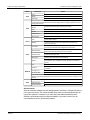
ION Setup commands
Below is a complete list of commands available from the menu bar. Note that some
commands are disabled (grayed out), depending on your selection and the current view
mode.
Menu
File
© 2012 Schneider Electric. All rights reserved.
Command
Effect
Save
Saves the network configuration file (ionsetup.dat)
Page Setup
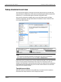
Determines the paper size and orientation for printing
Print
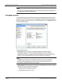
Prints the active document
Exit
Exits the ION Setup program
Page 33 of 147
Chapter 3: Configuring ION Setup
ION Setup 3.0 Device configuration guide
Menu
Edit
Command
Effect
Copy
Copies the selection to the clipboard
Delete
Removes the selected item
Properties
Displays the properties of the selected item
The View menu consist of two selection sets. The first set lets you display sites only, groups only,
or both.The second selection set lets you set the display mode for configuring (setup screens) or
viewing (data screens).
View
Both Sites and
Groups
Displays both site information and group information
Sites
Displays only site information
Groups
Displays only group information
Setup Screens
Sets the screen for configuration only
Data Screens
Sets the screen for displaying data only
Item
Displays the New Network Item dialog box, where you can add new
groups, sites or meters
Module
Creates a new ION module in the selected ION module folder (in
Advanced mode only)
Chart Data
Displays the Chart Properties dialog box, where you can select the data
you want to plot and determine the appearance of the chart
Broadcast Time
Displays the Broadcast Time dialog box, where you can broadcast the
present PC time to all the devices in one or more sites
Modem Control
Displays the Modem Control dialog box, where you can select which
modem site you want to dial
Diagnostics
Displays diagnostics data for the selected item
Options
Displays the Options dialog box, where you can set the directory location
for ION Setup, view, confirmation, security, alarming and convention
options
Tile
Displays all open windows, arranged in non-overlapping tiles
Cascade
Displays all open windows, arranged in an overlapping fashion
(cascaded)
Arrange Icons
Arranges the minimized window icons
Close All Tables
Closes all open windows except the Network Viewer window
Insert
Tools
Window
You can also use the Window menu to select from multiple open windows. A list of open windows
appears, with a check mark beside the active window. Select another window to change the active
window.
Help
Contents
Displays the contents of ION Setup Help
Visit home page
Provides link to www.schneider-electric.com.
About ION Setup
Displays the version, build and copyright information for ION Setup
Shortcut menus
Shortcut menus are available in the left and right panes of ION Setup. To display the shortcut
menu, right-click an item. The choices available in the shortcut menu are determined by the
type of item selected. For example, if you select the External Boolean Modules folder,
available commands are Insert Item and Insert Module. If you select a device icon, the
commands are Insert Item, Delete and Properties.
Page 34
© 2012 Schneider Electric. All rights reserved.
Network and Content Viewer icons
The icons below represent the items in the Network and Content Viewers. All icons, except
the system icon and workstation icon, can be added or deleted.
This is the system icon. It represents the entire network, including the workstation
running ION Setup and all connected devices. It is the top level of the Network
Viewer. It cannot be deleted or changed.
This represents the workstation that is running ION Setup. It cannot be deleted or
changed.
This represents a serial site (RS-232 or RS-485 connection).
This represents a modem site.
This represents a radio modem site.
This represents an Ethernet site.
This represents a logical group. Groups can have descriptive labels.
This represents an Ethernet Gateway site.
This represents an ION meter or other device. ION Setup can support up to 128
devices per site.
These icons appear on the right pane and represent groups of setup or display
parameters, or ION modules.
These icons represent ION modules that have gone off-line due to setup or
connection (e.g. circular links) errors.
These icons contain ION modules in ION-compliant devices. They are also used
to organize group display screens and setup screens.
Viewing options
The ION Setup Content Viewer can display either setup screens or data screens. The
selected view mode determines which type of screens ION Setup displays. Setup screens
are displayed the first time ION Setup is started. Once you have finished configuring the
devices on your network, you can switch to data display mode. The options available are
View Setup Screens or View Data Screens. The next time you start ION Setup, the Content
Viewer will display data in the mode you have selected.
View modes
View setup screens
Select the Setup Screens mode (View > Setup Screens) if you want to configure the setup
registers or edit ION module links in a device.
View data screens
Select the Data Screens mode (View > Data Screens) if you want to display data. ION
Setup can display real-time data for meters and other supported devices.
© 2012 Schneider Electric. All rights reserved.
Page 35 of 147
Chapter 3: Configuring ION Setup
ION Setup 3.0 Device configuration guide
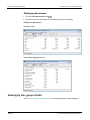
Displaying data screens
1. Click the View Data Screens button
.
2. Select the meter icon, then double-click the data screen you want to display.
Examples of data screens
Real-Time screen
Power Quality Aggregator screen
Viewing by site, group or both
See "Working in Network mode" on page 54 for detailed information on sites and groups.
Page 36
© 2012 Schneider Electric. All rights reserved.
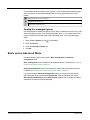
You can display network items by site or by group, or you can display both sites and groups.
Select the option you want under the View menu (or click the appropriate button on the
toolbar).
Displays both site and group information
Displays site information only
Displays group information only
Viewing the unassigned group ION Setup requires all meters to be part of a group. When you add a new meter to a site, ION
Setup automatically assigns it to a default group called “Group 1”. If you delete a meter from
a group, ION Setup moves that meter to the Unassigned group. To view the Unassigned
group:
1. Select Tools > Options (or click
on the toolbar).
2. Select the View tab.
3. Select the Unassigned Group box.
4. Click OK.
Basic versus Advanced Mode
ION Setup displays setup screens either in Basic Configuration or Advanced
Configuration mode.
Basic Configuration mode is available for all supported devices. For details, see "Working
in Basic Configuration mode" on page 66.
Advanced Configuration mode is only available on meters that use the ION architecture.
For details, see "Working in Advanced Configuration mode" on page 72.
If your meter supports Advanced Configuration mode, you can switch to that mode by
right-clicking the meter icon and selecting Properties. Click the Tools tab, then select
Show Advanced ION Setup from the Device Setup dropdown list. Click OK. All modules
available for the selected meter are displayed.
© 2012 Schneider Electric. All rights reserved.
Page 37 of 147
Chapter 3: Configuring ION Setup
ION Setup 3.0 Device configuration guide
Tip
For devices that support Advanced Configuration mode, hold down CTRL and click
the meter icon to switch (toggle) between Basic Configuration mode and Advanced
Configuration mode.
Related topics
• "Grouping devices" on page 60
• "Assigning a device to a group" on page 61
• "Adding and configuring sites" on page 56
Setting up options
After you have installed ION Setup and connected your devices and communication
hardware, you are ready to use the software.
Before you begin
Initially you are the administrator for ION Setup. Set your desired options before granting
access to other users.
Page 38
© 2012 Schneider Electric. All rights reserved.
Note
Some of the options are available only at the supervisor security level. See "Applying
security" on page 43 for more detailed information on the security systems in ION Setup.
Once you select your preferred options, you must restart ION Setup for the changes to
take effect.
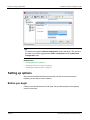
Select Tools > Options (or click
on the toolbar). The Options dialog box appears and
shows six tabs:
• Directories
• View
• Confirmation
• Security
• HHF (hand-held format)
• Conventions
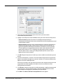
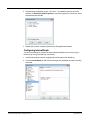
Directories tab The Directories tab specifies the path where ION Setup is installed. This option is available
to Supervisor-level personnel only. It is not recommended to move the ION Setup program
(IONSetup.exe) or rename the directory where the program resides.
NetInfo directory: Specifies the location for the ION Setup network configuration file,
ionsetup.dat. Changes made in ION Setup are stored in this file. If you move the
ionsetup.dat file or rename its directory, enter the new location or name here.
Program directory: Specifies the location for the ION Setup program, IONSetup.exe. If you
move the ION Setup program or rename its directory, enter the new directory location or
name here.
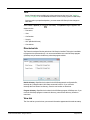
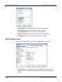
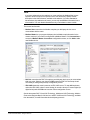
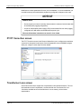
View tab
The View tab lets you select how your network information appears and the mode at startup.
© 2012 Schneider Electric. All rights reserved.
Page 39 of 147
Chapter 3: Configuring ION Setup
ION Setup 3.0 Device configuration guide
Unassigned Group: If you select this check box, ION Setup displays the Unassigned
group, which contains all the meters that you have not yet assigned to any group. Note that if
you delete a device in a defined group, that device is moved to the Unassigned group. This
option is available only to Supervisor-level personnel.
Connect on Selection: If you select this check box, ION Setup automatically attempts to
connect with a device when you click on a device icon in the Network Viewer. If this option is
not selected, a prompt appears when you click on a device icon, giving you the option to
connect.
Startup Mode: This option lets you select how ION Setup starts. Select the mode you want
to use from the list. See "Startup and View modes" on page 24 for a description of the startup
modes.
Sort Network Items: If you select this check box, ION Setup automatically sorts
alphabetically all sites and devices.
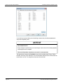
Confirmation tab The Confirmation tab lets you configure ION Setup to prompt you with a confirmation dialog
before executing the selected command. This option is available only to Supervisor-level
personnel.
By default, all check boxes in the Confirmation tab are selected.
• Confirm Deletes: Displays a Yes/No prompt before deleting the selected item.
• Confirm Copies: Displays a Yes/No prompt before copying (cloning) a certain meter’s
configuration onto another.
• Confirm Moves: Displays a Yes/No prompt before moving a meter to a different group.
• Confirm Triggers with Password: Displays an OK/Cancel prompt along with a
password field before executing external pulse commands (such as triggering a waveform
or resetting/clearing a register).
Page 40
© 2012 Schneider Electric. All rights reserved.
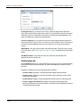
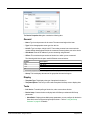
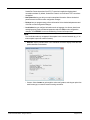
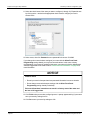
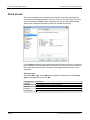
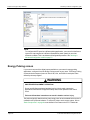
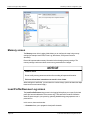
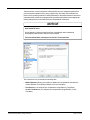
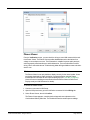
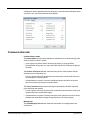
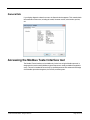
Security tab
The Security tab allows users to change their logon password for ION Setup. It also allows
Supervisor-level personnel to add or delete users and edit users' passwords. See "Applying
security" on page 43 for more information.
GroupUse this list to select the group/security level (see above) for a new or existing
user. This option is available for Supervisor-level personnel only.
Users: This box displays the user names that belong to the selected group/security level.
The options in this box are available to Supervisor-level personnel only.
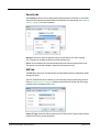
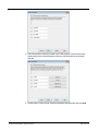
HHF tab
The HHF tab is where you can enter MV-90 .hhf (hand-held format) file configuration details
through ION Setup.
The HHF information must be entered if you are collecting revenue log data using .hhf files.
Refer to "Reports screen" on page 125 and the technical note MV-90 and ION Technology
available at www.schneider-electric.com.
Device ID Type: Select this field to specify the HHF file Device ID Type so that it matches
the Device ID field in your MV-90 system. © 2012 Schneider Electric. All rights reserved.
Page 41 of 147
Chapter 3: Configuring ION Setup
ION Setup 3.0 Device configuration guide
Hemisphere: Select the hemisphere in which the meter resides (i.e., Northern or Southern).
TIM Number: Enter the number you mapped to your TIM_ION module in your MV-90
system.
File Format: Select the E-File (engineering unit) or P-File (pulse unit) MV-90 data format.
NOTICE
LOSS OF DATA
Load profile/revenue log must be configured for pulse data if the P-File MV-90 data is
required.
Failure to follow these instructions can result in loss of data.
Refer to "Load Profile/Revenue Log screen" on page 106for more details.
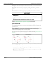
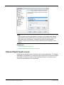
Conventions tab
The Conventinos tab allows you to set how data is displayed in ION Setup for phasor and
power factor sign.
Phasor Rotation: This option lets you select the phasor rotation for real-time phasor display.
You can set the display to rotate clockwise (90 degrees at the 6 o’clock position) or
counterclockwise (90 degrees at the 12 o’clock position). This allows you to alter the phasor display angle so indicators are visible ("Phasor Viewer" on
page 123).
Clockwise
Counterclockwise
Delta Vector Display: This lets you select how vector diagrams are displayed in ION Setup
for meters in Delta mode: • Instrument: Vectors appear 60 degrees apart, showing the actual voltage and current
values that the meter is measuring.
• System: Vectors appear 120 degrees apart, showing true system operation even though
IB and VCA are calculated values.
Page 42
© 2012 Schneider Electric. All rights reserved.
PF Convention: This sets the power factor sign convention.
• IEEE (Lead+/Lag-/0 to 100%): Use for IEEE meters. The sign of the power factor is
converted to lead or lag, and the power factor value is expressed as a percentage.
• IEC (+/-/0 to 1.000): Use for IEC meters. The power factor sign is not interpreted, and the
power factor value is expressed as a decimal fraction of one.
Applying security
Note
You can only create users in Power User startup mode and cannot switch to other
modes if non-default users exist in ION Setup. If you create a user in another mode, ION
Setup switches to Power User mode. The default user is supervisor (username) and 0
(password). See "Starting ION Setup" on page 24 for information startup modes.
ION Setup provides a four-level security access system. Supervisor-level personnel can
control access and define which functions are available to each user by grouping the users
according to security level, as follows: • Supervisor: This level is for management or supervisory personnel. This permits access
to all device configuration functions, including the security list, system/network
configuration, data display functions, and saving the default security configuration files.
• Operator: This level is for high level system operators. This permits access to system
configuration and data display functions. Operators should be well trained in operating
ION Setup.
• Controller: This level allows a controller to display data but not to change configuration of
ION Setup or of meters. This level also allows a controller to operate triggers.
• Users: This is suitable for personnel that use ION Setup on a regular basis and who
inform Supervisors or Operators of alarm conditions.
Note
ION Setup supports a maximum of 50 users.
For meter-specific security information, see the description of the Setup Assistant’s
"Security screen" on page 88.
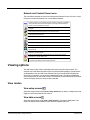
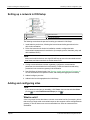
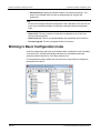
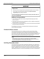
Creating or modifying ION Setup user accounts
This function is only available to Supervisor-level personnel.
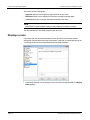
1. In the Network Viewer, select Tools > Options (or click
).
The Options dialog box appears.
© 2012 Schneider Electric. All rights reserved.
Page 43 of 147
Chapter 3: Configuring ION Setup
ION Setup 3.0 Device configuration guide
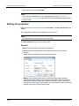
2. Select the Security tab and use the available buttons to add new accounts, delete
existing accounts or edit existing accounts (for example, to change password
information). Both user names and passwords are case sensitive.
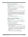
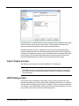
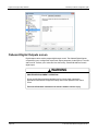
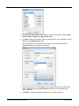
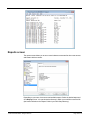
Creating new user accounts:
Only Supervisor-level users can create new user accounts.
1. Select the new users security level from the Group list, then click Add.
2. Type the new user name in the Log On field. The name you enter must be unique.
3. Type the new password in the New Password field then re-type the password in the
Confirm Password field.
4. Click OK. The new user is added.
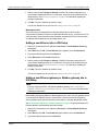
Editing existing user accounts:
Supervisor-level users can edit any account; users with security levels can edit their own
accounts.
1. Select the security level of the user account you want to change from the Group list, then
select the user name from the Users list and click Edit.
• To change a user name, type the new user name in the Log On field and type the
current password in the New Password and Confirm Password fields.
• To change a password, type the new password in the New Password field then re-type
it in the Confirm Password field.
Page 44
© 2012 Schneider Electric. All rights reserved.
2. Click OK.
Deleting user accounts:
Only Supervisor-level users can delete user accounts.
1. Select the security level of the user account you want to delete from the Group list, then
select the user name from the Users list.
2. Click Delete. The user account is deleted.
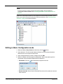
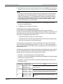
Note
The default security configuration files are set to read-only by default. To overwrite a file,
right-click on the file in the Save As screen and select Properties. In the General tab,
remove the checkmark beside the Read-only attribute and click OK. You should now be
able to overwrite the default security configuration file.
© 2012 Schneider Electric. All rights reserved.
Page 45 of 147
Chapter 3: Configuring ION Setup
Page 46 of 147
ION Setup 3.0 User Guide
© 2012 Schneider Electric. All rights reserved.
Chapter 4: Adding and configuring devices
This section describes the difference between Single Device and Network mode. It outlines
Network mode procedures for adding sites, groups and devices. This section also explains
how to configure devices in Basic Configuration mode and Advanced Configuration mode.
WARNING
UNINTENDED EQUIPMENT OPERATION
• Do not use ION Setup and associated devices for critical control or protection
applications where human or equipment safety relies on the operation of the control
circuit.
• Do not incorrectly configure ION Setup and its associated devices; this can lead to
incorrect reports and/or data results.
Failure to follow these instructions can result in death or serious injury.
Additional topics explain how to use your meter as an Ethernet Gateway (EtherGate) or
Modbus Gateway, how to perform time synchronization, and how to copy a meter’s setup
configuration onto another meter of the same type.
Note
Some devices require additional configuration in order to access and modify certain
setup parameters. For example, a revenue-class or hardware locked meter must be
unlocked before you can configure it. Refer to the device’s documentation for unlocking
and basic setup procedures.
In this section
Single Device mode and Network mode
48
Working in Single Device mode
50
Using serial communications
51
Using modem communications
51
Using Ethernet communications
52
Using offline programming
52
Working in Network mode
54
Setting up a network in ION Setup
56
Adding and configuring sites
56
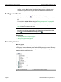
Adding a new device
60
Grouping devices
60
Assigning a device to a group
61
© 2012 Schneider Electric. All rights reserved.
Page 47 of 147
Chapter 4: Adding and configuring devices
ION Setup 3.0 Device configuration guide
Removing items from the network
61
Editing site properties
62
Editing group properties
64
Editing meter properties
64
Working in Basic Configuration mode
66
Editing in Basic Configuration mode
67
Setup screen examples
68
Errors
71
Typical meter setup parameters
71
Working in Advanced Configuration mode
72
Synchronizing the time across devices
78
ION meter cloning
78
Single Device mode and Network mode
ION Setup provides two modes of operation: Single Device mode and Network mode. As
the name indicates, Single Device mode allows you to communicate with and quickly
configure one device, and is frequently used by metershop technicians. The Network mode
allows you to configure multiple devices, sites, and groups, and is especially useful if you
require frequent communications with multiple devices. For details on communicating with
and configuring a device in Single Device mode, see "Working in Single Device mode" on
page 50. For details on using Network mode, see "Working in Network mode" on page 54.
Page 48
© 2012 Schneider Electric. All rights reserved.
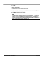
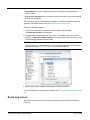
Single device mode
A
In Single Device mode, you can only view the
device to which you are connected
Network mode
B
In Network mode, you can see all of the devices
that are part of your network
When in Power User startup mode, ION Setup remembers the settings (Network or Single
Device mode) from its last session and by default selects or clears the Single Device Mode
option in the login screen. For Network and Metershop Technician startup modes, ION
Setup automatically bypasses the login screen and goes directly into either Network mode
or Single Device mode. For more information, refer to "Startup and View modes" on page
24.
Note
While in Single Device mode, the Network Viewer only displays the meter to which you
are connected. To view other meters on your network, you must be logged on in
Network mode.
Logging on in a different mode
The instructions for logging on in a different mode of operation depend on the startup mode
you are currently using for ION Setup.
© 2012 Schneider Electric. All rights reserved.
Page 49 of 147
Chapter 4: Adding and configuring devices
ION Setup 3.0 Device configuration guide
Switching modes when in Power User startup mode
1. Click File > Exit or click the exit icon. The Exit Options dialog box appears (the
Shutdown Program option is selected by default). Select User Logoff and click OK.
The ION Setup System Log on screen appears.
2. Select or clear the Single ION device configuration mode check box.
3. Click OK and log on again.
Switching modes when in Network or Metershop Technician startup mode
If you are in Network or Metershop Technician startup mode, you must change your startup
mode by going to Tools > Options > View. Refer to "Switching between startup modes" on
page 26 for more information.
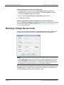
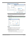
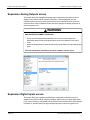
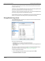
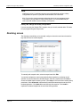
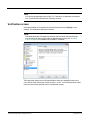
Working in Single Device mode
When you log on in Single Device mode, the Connection Type dialog box appears. Select
your desired connection type and enter the required information in the fields provided.
Note
Using Single Device mode is recommended only for working with devices with the ION
protocol. Single Device mode is also not to be used with the ION6200 meter. It can be
used with the E5600 via the front optical only. ModemGate, Ethergate and RS-485 are to
be avoided when more than a single device is on the hardwire connection.
Once you have entered the connection information and configured your site properties using
the Settings button, click OK. The ION Setup Network Viewer opens. The device you are
connected to appears in the left pane of the Network Viewer.
Page 50
© 2012 Schneider Electric. All rights reserved.
Tip
You can configure ION Setup to skip the login dialog box and always open in Single
Device configuration mode. See "Starting ION Setup" on page 24 for more information.
Using the Settings button
The Settings button lets you configure additional communications settings for the
connection you are using. Some settings are not configurable (or do not apply to the selected
connection type) — these are disabled (grayed out).
Click Settings to access the Site Properties dialog box, containing two tabs:
• General: allows connection changes (e.g. Comm Link, Link Type, Link Speed)
• Timings: allows timing alterations (e.g. Response Delay, Transmit Delay, Byte Timeout)
Using serial communications
To connect using serial communications, click Serial in the Connection Type dialog box
and select the appropriate serial port. Click the Settings button to set General and Timings
configurations.
Optical probe communications
To communicate with a meter through an optical probe, follow the setup instructions supplied
by the optical probe manufacturer. Use the probe to connect the meter to the
laptop/computer running ION Setup.
Note
For self-powered optical probes, you can change the DTR setting to “Probe Ctrl” to turn
on the probe only when it is communicating with the meter. Refer to "Timings " on page
63 for a description of each setting.
For more information on using optical probes with your device, refer to the technical note
Optical Magnetic Couplers available at www.schneider-electric.com.
Using modem communications
To connect via modem, select Modem in the Connection Type dialog box, enter the
modem’s phone number. Click the Settings button and enter the modem settings. Click the
Modem Profile button and follow the instructions on the Modem Profile Selection Wizard to
configure the local and remote modem properties.
© 2012 Schneider Electric. All rights reserved.
Page 51 of 147
Chapter 4: Adding and configuring devices
ION Setup 3.0 Device configuration guide
Note
To stop modem communications (for example, if the remote modem is not responding),
press the ESC key on your keyboard. ION Setup then attempts to stop modem
communication.
Using Ethernet communications
If your device has Ethernet capability, connect by entering the IP address of the device in the
Ethernet box of the Connection Type dialog box. Your IT department can supply IP address
information.
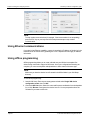
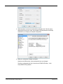
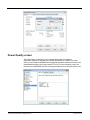
Using offline programming
Offline programming allows you to create, edit and test your ION device template files
without being connected to a physical ION meter. Once your configuration and testing are
complete, you can save templates and upload them to other meters of the same type.
Note
Make sure you have the desired .exe file stored in the Offline folder in your ION Setup
directory.
To use Offline programming:
1. Launch ION Setup. Enter any necessary password and select Single ION device
configuration mode, then click OK.
2. Choose the Off-line option. Select the meter and firmware combination from the dropdown
list, or click Browse to navigate to the desired .exe file. You are prompted to select the
firmware file you want to work with.
Page 52
© 2012 Schneider Electric. All rights reserved.
3. ION Setup takes a moment to load the offline configuration file. This file exactly
duplicates the function of a meter. Once loaded, ION Setup defaults to the Setup
Assistant for you to begin your template configuration.
4. Make your configuration changes as required.
When you exit Offline mode, you are prompted to save your changes.
The device configuration file (.dcf) is saved to the TEMPLATE folder (...\ION
Setup\TEMPLATE) by default.
© 2012 Schneider Electric. All rights reserved.
Page 53 of 147
Chapter 4: Adding and configuring devices
ION Setup 3.0 Device configuration guide
Note
Some modules are not copied during this procedure. See "Template paste options " on
page 85 for details.
Working in Network mode
Unlike Single Device mode, Network mode allows you to add sites, groups and multiple
devices, and save your network configuration.
Tip
You can configure ION Setup to always open in Network configuration mode. See
"Starting ION Setup" on page 24 for more information.
Page 54
© 2012 Schneider Electric. All rights reserved.
To add network items, do one of the following:
• Click the Insert an Item button
.
• Select Item from the Insert menu.
• Right-click anywhere on the screen to display the shortcut menu, then click Insert Item.
The New Network Item dialog box appears. Select the item that you want to add. Items that
can be added include Sites, Groups and Meters. Select where you want to attach the new
item from the Attach To list and click OK.
Tip
Right-click a specific item on the left pane that you want to add items to, and select
Insert Item to automatically set the Attach To option.
© 2012 Schneider Electric. All rights reserved.
Page 55 of 147
Chapter 4: Adding and configuring devices
ION Setup 3.0 Device configuration guide
Setting up a network in ION Setup
A
C
E
Ethernet site
Ethernet Gateway
Modem site
B
D
F
Ethernet devices
RS-485 devices
Remote serial device
The following summarizes the process for setting up a network in ION Setup:
1. Install and wire your devices, following the instructions and safety precautions in the
device's documentation.
2. Follow the instructions in the device installation manual to configure the basic
communications parameters for each device (for example, protocol, baud rate, parity and
device address/unit ID).
Note
Make sure that all the devices on a single RS-485 loop are set to the same baud rate and
data format, and that no two devices use the same unit ID.
3. If using a communications converter or gateway, configure its communications
parameters, then install and wire it to the meter(s). Follow the instructions and safety
precautions in the converter or gateway's documentation.
4. Start ION Setup in Network mode. See "Starting, logging on and logging off" on page 24
for more information on the operation modes, and starting and logging onto ION Setup.
5. Add and configure your sites.
6. Add each device to the appropriate site in ION Setup
Adding and configuring sites
Note
If you cannot see the sites you are adding, click View on the menu bar and select Sites
(or click
), or select Both Sites and Groups (or click
).
What is a site?
A site is a group of devices that share a common communications link (for example, devices
that are using a single serial communications port on the computer or share a single Ethernet
gateway). A site can have one or more connected devices. Sites are connected to the
workstation.
Page 56
© 2012 Schneider Electric. All rights reserved.
Adding a serial site in ION Setup
See "Using serial communications" on page 15 for general information on serial
communications and network setup.
1. Right-click the workstation icon and select Insert Item. The New Network Item dialog
box appears.
2. Select Site and click OK. The New Site dialog box appears. Select the General tab.
3. Type a name identifying the site in the Name box.
4. Select Serial from the Comm Link options.
5. Select the serial port on the computer that you are using to communicate with the meter(s)
from the Comm Port list.
6. Select the baud rate and data format you want to use for the site from the Port Settings
lists. These need to be set to the same value as the device(s) connected to the site.
7. Edit the values on the Timings and Polling, if needed. These tabs contain other site
communications parameters which, in most cases, do not need to be modified from the
default settings. See "Editing site properties" on page 62 for information regarding the
settings on these tabs.
8. Click OK. The site is added to the network viewer.
You can now add devices to your site; see "Adding a new device" on page 60.
Adding a new modem site in ION Setup
See "Using modem communications" on page 17 for general information on modem
communications and network setup.
1. Right-click the workstation icon and select Insert Item. The New Network Item dialog
box appears.
2. Select Site and click OK. The New Site dialog box appears. Select the General tab.
3. Type a name identifying the site in the Name box.
4. Select Modem from the Comm Link options.
5. Click Modem configuration. The Modem settings dialog box appears.
• Select the serial port on the computer that you are using to communicate with the local
modem from the Comm Port list.
• Select the baud rate and data format you want to use for the site from the Port Settings
lists. These need to be set to the same value as the device(s) connected to the site.
• Click Modem Profile to access the Modem Profile Selection Wizard and configure
the modem profile for the local and remote modems. Click Finish when you are done
with the wizard.
Click OK when you are finished to return to the New Site dialog box.
6. Type the phone number of the remote modem in the Phone Number box.
© 2012 Schneider Electric. All rights reserved.
Page 57 of 147
Chapter 4: Adding and configuring devices
ION Setup 3.0 Device configuration guide
7. Edit the values on the Timings and Polling, if needed. These tabs contain other site
communications parameters which, in most cases, do not need to be modified from the
default settings. See "Editing site properties" on page 62 for information regarding the
settings on these tabs.
8. Click OK. The site is added to the network viewer.
You can now add devices to your site; see "Adding a new device" on page 60.
ModemGate feature
Some ION meters are equipped with an internal modem that you can set up as a
communications gateway to connect to multiple RS-485 devices (e.g., on a remote site). For
more information, refer to the meter's documentation and the technical note The ION meter
as a ModemGate available at www.schneider-electric.com.
Adding a new Ethernet site in ION Setup
1. Right-click the workstation icon and select Insert Item. The New Network Item dialog
box appears.
2. Select Site and click OK. The New Site dialog box appears. Select the General tab.
3. Type a name identifying the site in the Name box.
4. Select Ethernet from the Comm Link options.
5. Edit the values on the Timings and Polling, if needed. These tabs contain other site
communications parameters which, in most cases, do not need to be modified from the
default settings. See "Editing site properties" on page 62 for information regarding the
settings on these tabs.
6. Click OK. The site is added to the network viewer.
You can now add devices to your site; see "Adding a new device" on page 60.
Adding a new Ethernet gateway or Modbus gateway site in
ION Setup
Note
If you are using an ION7550 / ION7650 as a Modbus gateway, see "Configuring the
ION7550 / ION7650 meter as a Modbus gateway " on page 59 for instructions rather than
following the steps below.
Before adding an Ethernet gateway or Modbus gateway site, make sure your gateway device
is connected to the Ethernet and your serial network of meters are wired to the gateway
device (and basic setup has been performed on each device, including the gateway meter).
See "Using Ethernet Gateways or Modbus gateways" on page 19 for general information on
Ethernet gateway communications and network setup.
1. Right-click the workstation icon and select Insert Item. The New Network Item dialog
box appears.
2. Select Site and click OK. The New Site dialog box appears. Select the General tab.
3. Type a name identifying the site in the Name box.
Page 58
© 2012 Schneider Electric. All rights reserved.
4. Select Ethernet from the Comm Link options then select the Gateway checkbox.
5. Type the IP address of the gateway device and select the port number from the dropdown
list in Gateway Info.
IP Port
Description
502
7801
7802
7803
Modbus TCP
EtherGate through COM1 of an ION meter
EtherGate through COM2 or COM4 of an ION meter
EtherGate through COM3 of an ION meter
6. Edit the values on the Timings and Polling, if needed. These tabs contain other site
communications parameters which, in most cases, do not need to be modified from the
default settings. See "Editing site properties" on page 62 for information regarding the
settings on these tabs.
7. Click OK. The site is added to the network viewer.
As a result:
• You can now add devices to your site.
• If supported, you can connect to and read data from your gateway device by adding it as
a stand-alone Ethernet device in ION Setup.
See "Adding a new device" on page 60 for additional information.
Configuring the ION7550 / ION7650 meter as a Modbus
gateway Before configuring an ION7550 / ION7650 as a Modbus gateway, make sure the ION7550 /
ION7650 meter is connected to the Ethernet, your serial meters are wired to the gateway
meter, and basic setup has been performed on each device, including the gateway meter.
See "Using Ethernet Gateways or Modbus gateways" on page 19 for general information on
Ethernet gateway communications and network setup.
Note
For Modbus TCP communications, the Ethernet IP port is hard-coded to port 502 on
ION7550/ION7650 meters. You do not need to set this in ION Setup.
When using an ION7550 / ION7650 as a Modbus gateway, you do not need to add it as a
gateway site in ION Setup; simply configure the meter as follows:
1. Add the meter as an Ethernet meter in ION Setup. See "Adding a new device" on page 60
for instructions.
2. Connect to the gateway meter in Basic Configuration mode.
3. Double-click the Setup Assistant icon to open it, then navigate to Communications >
Serial Settings.
4. Select the serial communications port that is connected to the downstream Modbus
devices. Set the Protocol to Modbus Master and verify that the baud rate and other
settings match with the downstream devices.
© 2012 Schneider Electric. All rights reserved.
Page 59 of 147
Chapter 4: Adding and configuring devices
ION Setup 3.0 Device configuration guide
5. Navigate to Communications > Network Settings. On the TCP/IP tab, select Modbus
Gateway, and click Edit. From the Select Modbus Gateway screen, select the serial
communications port connected to your downstream Modbus devices and click OK.
Adding a new device
1. Select Insert > Item (or click
). The New Network Item dialog appears.
2. Select Meter. Use the Attach To list to specify which site the meter belongs to and click
OK.
3. Fill in each field in the New Device dialog (see "Editing meter properties" on page 64 for
related information). The meter name must begin with a letter.
4. The meter icon appears under the site. Refer to "Working in Basic Configuration mode" on
page 66 for details on setting up the meter.
Note
If you cannot see the sites you are adding, click View on the menu bar and select Sites
(or click
), or select Both Sites and Groups (or click
).
Related Topics
• "Assigning a device to a group" on page 61
• "Editing meter properties" on page 64
Grouping devices
What is a group?
A group is a feature that lets you define a logical grouping of meters. For example, you can
have a group of meters dedicated to power quality monitoring or a group of meters defined by
location. Groups are always attached to the System icon. Devices within each group are
attached to both the group and the site.
A
Page 60
All of the meters in the site
B
Meters grouped by location or purpose
© 2012 Schneider Electric. All rights reserved.
Creating a group
1. Select Insert > Item (or click
on the toolbar). The New Network Item dialog appears:
2. Select Group and click OK.
3. Fill in each field in the New Group dialog box.
Note
If you cannot see the sites you are adding, click View on the menu bar and select Sites
(or click
), or select Both Sites and Groups (or click
).
Related topics
• "Editing group properties" on page 64
• "Viewing by site, group or both" on page 36
Assigning a device to a group
The ION Setup Network Viewer supports the same drag-and-drop feature available in
Windows Explorer. To assign a device to a group:
1. Select View > Both Sites and Groups (or click
on the toolbar).
2. If the group has not yet been created, create the group so you have a destination for
dragging. See "Creating a group" on page 61 for details.
3. In the Network Viewer, double-click the site icon that contains the target device to display
the target device in the Content Viewer.
4. Click the target device and drag it on top of the destination group icon. An icon for that
device appears under the group icon, as well as under the site it is attached to.
To assign a device to a different group, drag its icon from one group to the other.
Removing items from the network
To remove a group, site or meter from the network, select the item in the Network Viewer,
then do one of the following:
• Press the Delete key,
• Select Edit > Delete, or
© 2012 Schneider Electric. All rights reserved.
Page 61 of 147
Chapter 4: Adding and configuring devices
ION Setup 3.0 Device configuration guide
• Right-click the item, then select Delete.
Note
You cannot delete the System icon, the unassigned group icon (see "Viewing the
unassigned group " on page 37), the workstation icon, or the data display folders from the
Network Viewer.
Editing site properties
Right-click the site you want to edit, then select Properties. The Site Properties dialog box
appears.
The configurable site properties vary depending on the type of site.
Note
You cannot modify a site that has devices connected to it.
The Site Properties dialog box has the following tabs:
General
• Name: Enter a unique name for the site in the Name field.
• Comm Link: Select the appropriate communications type and fill in the required
information.
• Serial: Select the appropriate Comm Port and Port Settings.
• Modem: Enter the phone number and click the button beside Modem Settings to
configure your modem settings. Click the button beside Modem Profile to access the
Modem Profile Selection Wizard, which guides you through a series of configuration
screens to set up your local PC-side modem. Any remote modems must be configured
manually if necessary using a terminal program.
Page 62
© 2012 Schneider Electric. All rights reserved.
Note
To stop modem communications (for example, if the remote modem is not responding),
press the ESC key on your keyboard. When you do this, ION Setup attempts to stop
modem communication.
• Ethernet: Select the Gateway checkbox if the site is an Ethernet Gateway. Refer to
"Adding a new Ethernet gateway or Modbus gateway site in ION Setup" on page 58 for
more information.
Timings • Response Delay: Specify a Response Delay (in milliseconds).
• Transmit Delay: Specify a Transmit Delay (in milliseconds).
• Byte Timeout: Specify a Byte Timeout (in milliseconds).
• RTS (Ready to Send) Control: Specify an RS232/RS485 software flow control.
• Disabled: Software flow control is disabled.
• Force Off: Software flow control is set to off (RS232/RS485 line held low).
© 2012 Schneider Electric. All rights reserved.
Page 63 of 147
Chapter 4: Adding and configuring devices
ION Setup 3.0 Device configuration guide
• Force On: Software flow control is active for the entire message string, which holds the
RS232/RS485 line high for the complete message sequence. Use this setting for
powering external devices from the RS232/RS485 line.
• Toggle: Toggles the line between receive/transmit. Use this setting for direct
connection to COM32/COM128 or similar.
• Wait CTS: Waits for receipt of a Clear To Send message. Use this setting for active
flow control for reduced throughput devices (e.g., modems).
Note
The "Force ON" setting should only be used for probes that are powered from the serial
port. For serial probes, in ION Setup, set the RTS or DTS to "Force ON". For all other
probes, set RTS or DTS to "Force OFF".
• DTR (Data Terminal Ready): Specify a DTR line control.
• Disabled: No software DTR line control.
• Modem Ctrl: Forces the DTR line low upon “request communication end” failure. Use
this setting to force a modem disconnect.
• Force Off: Sets the DTR line low. Use this setting for optical probes on IEEE meters.
• Force On: Sets the DTR line high. Use this setting for optical probes on IEC meters.
• Probe Ctrl: Use this custom setting for self-powered probes to mitigate battery loss.
Polling
• Polling Method: Specify the polling method for the selected site from the dropdown list.
Supported options are Continuous, On Demand, or Scheduled.
• Edit Schedule: Edit the polling schedule for the selected site (or view the current
schedule used to poll the meters in the selected site).
• Next Connection: View when polling next occurs on the selected site.
• Broadcast Interval: Specify hours and minutes between polling intervals.
• Timezone: Specify local time zone.
Editing group properties
Right-click the group you want to edit, then select Properties. Type in a unique name for the
group and click OK.
Editing meter properties
Expand the site (by double-clicking the site icon) where your meter is located. Right-click the
meter icon, then select Properties.
Page 64
© 2012 Schneider Electric. All rights reserved.
The Device Properties dialog box contains the following tabs:
General
• Name: Type in a unique name for the meter. The name must begin with a letter.
• Type: Select the appropriate meter type from this list.
• Unit ID: Type in a unique, 4-digit Unit ID. The number you enter here must match the
number that has been programmed for the connected communications port on the device.
• IP Address: Enter the IP address if you are connecting using Ethernet.
• IP Port: This contains the port number of the device to which you are connected.
The following table lists the ports used for Ethernet communications:
IP Port1
Description
502
Modbus TCP
7700
ION (direct)
7701
Modbus RTU over Ethernet
23
Telnet (used for meter diagnostics)
1 Some meters support email (SMTP through port 25) and webpages (HTTP through port 80).
• Group: This box displays the name of the group that the meter belongs to.
Display
• Template Type: This displays the type of template for the device.
• Template Options: This lets you select which template ION Setup uses to display data.
Tools
• Poll Device: To enable polling of the device, make sure to select this box.
• Device Setup: Choose whether to display basic ION Setup or advanced ION Setup
parameters.
• Show Basic: Displays the available setup parameters you can configure for the device.
Some devices are configured using Setup Assistant — refer to "Using the Setup
Assistant" on page 81 for details.
© 2012 Schneider Electric. All rights reserved.
Page 65 of 147
Chapter 4: Adding and configuring devices
ION Setup 3.0 Device configuration guide
• Show Advanced: Displays all available modules in the selected ION device. This
option is only available on devices that are designed and built using the ION
architecture.
Tip
For devices that support Advanced Configuration mode, hold down CTRL and click the
meter icon to switch between Basic Configuration mode and Advanced Configuration
mode.
• Store to File: This lets you save the current device configuration to a .dcf file in the
security folder of the project.
• Restore from File: This lets you upload a different .dcf configuration file to the device.
• Firmware Upgrade: This lets you upgrade the device’s firmware.
Working in Basic Configuration mode
All devices supported by ION Setup can be edited in Basic Configuration mode. Depending
on the device type, ION Setup may display individual icons that represent the setup
parameter groups for that device, or the Setup Assistant icon.
For setup parameter groups, double-click the icons in the Content Viewer to configure the
parameters for the device.
Page 66
© 2012 Schneider Electric. All rights reserved.
Note
For devices that do not have the Setup Assistant available, there are additional
configuration wizards available. See "Accessing the Modbus Tester Interface tool" on
page 141.
Double-click the Setup Assistant icon in the right pane to start the Setup Assistant, which
allows you to specify setup and configuration values for the device. See "Using the Setup
Assistant" on page 81 for further information.
Editing in Basic Configuration mode
1. Make sure View > Setup Screens is selected (or click the
button).
2. Select the device. For devices that display individual icons for the setup parameters,
double-click the icon to open the setup screen.
3. Select a setup parameter you want to change, then click Edit.
4. Make the changes to the setup register as appropriate. Most setup register types are
enumerated, numeric-bounded, elapsed interval or date/time:
• Enumerated: Click the
button and select an option from the list.
• Numeric bounded: Select Numeric Bounded Format from the list and enter a numeric
value in the box.
© 2012 Schneider Electric. All rights reserved.
Page 67 of 147
Chapter 4: Adding and configuring devices
ION Setup 3.0 Device configuration guide
• Elapsed Interval: Select Elapsed Interval Format from the list. Enter the days, hours,
minutes and seconds, and use the +/- drop down to indicate the interval direction.
• Date/Time: Select Date/Time Format from the list. Select the month, day and year and
enter the time.
5. Click OK.
6. Make changes to the other setup registers if required.
7. Click Send to save your changes to the meter.
Setup screen examples
There are some setup register types that allow you to select one or more options, as shown
below:
Example 1
Click a checkbox to select (check), or clear (uncheck), your selection. If there are additional
setup screens, click Next.
Page 68
© 2012 Schneider Electric. All rights reserved.
After you configure the remaining setup parameters, click Finish.
Example 2
Click an item in the Available field to highlight it, then click the
list of selected items.
button to add it the
Click an item in the Selected field to highlight it, then click the
from the list of selected items.
button to remove it
© 2012 Schneider Electric. All rights reserved.
Page 69 of 147
Chapter 4: Adding and configuring devices
ION Setup 3.0 Device configuration guide
Example 3
In a parameter setup dialog, use the fields and controls on the window to define and configure
the selected (highlighted) parameter in the left field.
To add a new parameter to the list, click New. To remove an existing parameter, select it,
then click Delete. You typically use Delete when you want to make room for a new
parameter after the maximum limit has been reached.
Example 4
To search for a parameter, enter the parameter name in the Parameter field and click Search.
The parameter is selected and its location as displayed beside Source. Click the "+" symbol
to expand the list to find your parameter.
Page 70
© 2012 Schneider Electric. All rights reserved.
Errors
If you try to enter a value that is outside the limits for the register, ION Setup displays the
error, either on the status bar (near the bottom left corner of the window), or in a popup dialog.
Typical meter setup parameters
Some setup parameter groups are common and available to all meter types (such as Basic
Setup, for configuring PT and CT ratios and other system parameters). Other setup
parameter groups are available only on meter types that support certain features (such as
Waveform Capture). Refer to your meter documentation for information on how to set up the
features supported by your meter. For information on how to use ION Setup to configure
devices that are not based upon the ION protocol, refer to the ION Setup Device
Configuration Guide.
Modbus protocol considerations
Serial communications (Modbus RTU): To avoid communications issues, make sure all
devices on the serial communications bus are set to the same data format.
© 2012 Schneider Electric. All rights reserved.
Page 71 of 147
Chapter 4: Adding and configuring devices
ION Setup 3.0 Device configuration guide
Note
8N1 (8 data bits, no parity, 1 stop bit) is the default serial communications port setting for
most ION meters.
Ethernet communications (Modbus TCP): For meters that use Modbus TCP to
communicate through Ethernet, enter “502” in the IP Port box when adding the meter in ION
Setup (port 502 is used for Modbus TCP communications).
Working in Advanced Configuration mode
Advanced Configuration mode is available on meters that are designed and built using the
ION architecture.
Tip
For devices that support Advanced Configuration mode, hold down CTRL and click the
meter icon to switch between Basic Configuration mode and Advanced Configuration
mode.
For information on basic configuration using the Setup Assistant, see "Setup Assistant
overview" on page 82.
If you require advanced programming or configuration, it is recommended that you use the
Designer component of ION Enterprise software. Its graphical interface lets you view links
and modules, include descriptive text about the configuration, and troubleshoot any
frameworks you create.
To access Advanced Configuration mode
Access the ION modules on a meter and create new modules by following these steps:
1. Go to the site, right-click on a meter and select Properties.
2. Click the Tools tab and select Advanced ION Setup from the Device Setup dropdown
menu.
It may take several seconds for the ION modules to load onto your screen.
3. Double-click an ION module to view/edit the module’s configuration.
Page 72
© 2012 Schneider Electric. All rights reserved.
Note
When working in Network mode, Advanced and Basic views are device-specific rather
than global. This allows you to view one meter in Advanced mode and another in Basic
mode.
Overview of ION architecture ION architecture forms the basis of every component in the ION network. This architecture
defines the logical pathways used to control information and data when moving between
individual functional blocks within a meter, between meters, or between meters and other
parts in the power monitoring and control system.
ION architecture is object oriented, giving you exceptional system flexibility. ION meters can
be configured to dedicate their resources to suit your application.
The fundamental objects that comprise the ION architecture are ION modules and ION
registers.
For more information on ION architecture, refer to the ION Reference. For more information
on the modules available in your device, refer to the ION Device Templates Reference on
www.schneider-electric.com.
© 2012 Schneider Electric. All rights reserved.
Page 73 of 147
Chapter 4: Adding and configuring devices
ION Setup 3.0 Device configuration guide
ION modules
ION modules are building blocks of functionality that link together to change setup as
required. Each ION module is comparable to some part of a conventional power monitoring
system: the Power Meter module is similar in function to a digital multimeter; the Thermal
Demand module is similar to a conventional demand meter; the Integrator module is similar
to an energy meter.
Over 80 types of ION modules are defined in ION architecture. Their functions range from
basic real-time power measurements to comprehensive waveform data logging and setpoint
control.
Collectively, these ION modules cover the complete range of power monitoring and control
capabilities. Some examples of ION modules are:
• The Power Meter module provides the functionality of a discrete power measuring
instrument, such as a conventional kW meter, or the basic measurements provided by
multifunctional meters like the ION6200.
• The Maximum module is comparable to a peak register, which keeps track of variables
such as peak demand. A Maximum module in the ION architecture, however, has the
flexibility to keep track of the maximum value for any programmed parameter.
• The Data Recorder module models the behavior of a conventional strip chart recorder,
which may be used to track information such as variations in current flow. This module
stores values so that they can be displayed or printed for later analysis. Furthermore,
since the Data Recorder can sample at sub-millisecond intervals, it can also be used as a
very high-speed recorder for harmonics analysis and fault detection.
The types of modules available in an ION meter and the number of each type that may be
used depend on the kind of device. The ION7650, for example, has 50 Data Recorder
modules. The ION6200, on the other hand, has none. Refer the documentation for your
devices to learn of the available modules.
ION registers
ION modules can have a number of setup registers and output registers. ION registers are
data storage locations; the module reads data through its input(s), manipulates the data
according to its function and the values in the setup registers, and writes the result to its
output register(s). The output registers might contain maximum RMS readings for threephase current or describe the high-speed digitized data points for 32 cycles of a singlevoltage phase.
Module links
An ION meter is customized by linking ION modules. The output registers of a module can
be linked to the input registers of other modules. This allows data to flow from one module to
the next. The setup registers are internal to each module, so they do not require linking.
Register classes
Not all output registers can serve as inputs for all modules. There are different classes of
registers, each capable of holding different types of information. For example, numeric
registers contain numbers, Boolean registers contain ON or OFF information and waveform
Page 74
© 2012 Schneider Electric. All rights reserved.
registers contain waveform data. These registers are described in the ION Reference. To
link two ION modules together, the output registers of the first module must contain
information the next module can use.
Creating new ION modules 1. From the left pane (Network Viewer), click the folder for the module type you want to
create.
2. Select Insert > Module (or click
on the toolbar).
If there are sufficient resources on the device and available modules of that type, the new
module appears on the right pane.
Tip
To determine the number of modules of a particular type that are in use, select the folder
in the left pane then hover over it. A message appears stating how many modules of that
type are in use and how many are available (for example, Modules used: 17 of 20 (3
available)).
To determine the modules available on an ION device, refer to the ION Device Template
Reference available at www.schneider-electric.com.
Creating custom module labels
ION Setup allows you to create custom labels for modules. To create a custom label:
1. Right-click on the module icon you want to label.
2. Select Rename from the pop-up menu.
3. Type the new label into the Name box.
4. Click Send to send your changes to the device.
Note
The number of labels available on an ION meter is limited. You may want to restrict the
use of custom labels to output registers only (where they are typically more useful). See
"Customizing ION module output register labels" on page 78 for more information.
Resetting custom module labels to their default labels
To reset a custom module label to its default label (and allow other custom labels to be
created if you have run out of space):
1. Right-click on the icon of the module with the custom label you want to reset.
2. Select Rename from the pop-up menu.
3. Delete the custom label completely. You do not need to type the default label in the field.
4. Click Send to send your changes to the device. The label is reset to the default.
© 2012 Schneider Electric. All rights reserved.
Page 75 of 147
Chapter 4: Adding and configuring devices
ION Setup 3.0 Device configuration guide
Configuring an ION Module setup register
ION Setup lets you change the values for numeric bounded registers, enumerated registers,
and string setup registers. Setup registers that are not of these three classes cannot be
configured using ION Setup.
1. Double-click on the module you want to configure.
2. Select the Setup Registers tab.
3. The Parameters box lists all the setup registers of the selected module and their settings.
To change a setup register, select it and click Edit.
• If the selected setup register is a numeric bounded register, type a value into the
provided box and click OK.
• If the selected setup register is an enumerated register, select an option from the list
and click OK.
• If the selected setup register is a string register, type the string in the provided box and
click OK.
4. Click Send to send your changes to the device.
Linking ION modules
ION Setup lets you link the output register of an ION module to the input register of another
ION module on the same device. This operation must be performed before reconfiguring ION
devices.
To create a link between ION modules:
1. Double-click the module whose input you want to link.
2. Select the Inputs tab.
3. The Parameters box lists all the inputs of the selected module as well as the labels of the
output registers that are currently linked to each input. To create a new link (or change an
existing one), select the input and click the Edit button.
4. The ION Input Selection dialog box appears. Complete this dialog box (for more detail,
see the topic "ION Input selection dialog box" on page 76).
5. The label of the output register you selected appears beside the input in the Parameters
box.
6. Click Send to send your changes to the device.
ION Input selection dialog box
When you click on the “+” beside an item in the tree, it expands to show all the items beneath
it in the hierarchy. For example, if you click on the Sliding Window Demand modules, all the
available Sliding Window Demand modules are displayed. If you click on a specific module,
all the output registers of that module are revealed.
As you navigate the tree, ION Setup caches the branches you open. Thus, if you open a
branch of the tree that you already looked at, ION Setup can display it immediately, without
Page 76
© 2012 Schneider Electric. All rights reserved.
communications delays. The parts of the tree you have opened are identified by a small box
with a “+” or “–” sign beside them (the “+” sign indicates that the item can be expanded further
and the “-” sign indicates that the branch has already been expanded).
Note
The cached tree is only maintained until you open the ION tree of another ION device;
once you change to another ION device, the cache is cleared.
There are several ways to select an output register:
• You can use the tree to select the module type, module and register. At the top of the
dialog box, the full path of the register is shown as \\Device Name\ION module type\ION
module and the name of the register appears in the Parameter box. Only those output
registers of the class appropriate for the selected input are displayed (for more information
on registers, register classes and module links, see "Overview of ION architecture " on
page 73).
• If you already know the label of the register you want and you have already opened that
branch of the tree, you can simply type the label of the register you want into the
Parameter box and click the Search button. If the register is in the ION Setup cache, the
path of the register appears above the Parameter box and the OK button becomes
available. If the register is not in the cache or has been typed incorrectly, the message “No
match found in cache” is displayed.
• If you know the handle of the register you want, you can bypass the ION tree altogether
and simply type in the handle. This is the fastest method of accessing an ION register;
however, it does not add the register to the cache.
Once you have selected an output register, click the OK button to return to the module’s
configuration dialog box. When you are finished linking, click Send to save your changes to
the meter.
Deleting links between ION modules
To delete a link between two ION modules:
1. Double-click the module whose input you want to unlink.
2. Select the Inputs tab.
3. The Parameters box lists all the inputs of the selected module as well as the labels of the
output registers that are currently linked to each input.
NOTICE
UNINTENDED DEVICE OPERATION
Do not delete any ION modules without knowing which modules are dependent on it.
Failure to follow these instructions can result in the unintended operation of the
remaining modules.
4. Select the input, then click Delete.
5. Click Send to send your changes to the device.
© 2012 Schneider Electric. All rights reserved.
Page 77 of 147
Chapter 4: Adding and configuring devices
ION Setup 3.0 Device configuration guide
Viewing ION module output registers
1. Double-click the module whose output registers you want to view.
2. Select the Output Registers tab.
3. The Parameters box lists all the output registers of the selected module.
Customizing ION module output register labels
Most output register labels can be customized. To customize an output register label:
1. Double-click the module whose output register you want to label.
2. Select the Output Registers tab.
3. The Parameters box lists all the output registers of the selected module. Select the
register you want to label, then click Edit (or double-click the register).
4. Type the custom label in the box, then click OK. Some ION devices limit the number of
characters a custom label can have.
5. Click Send to save your changes to the device.
Synchronizing the time across devices
This section applies to the ION8800, ION8600, ION8650, ION7550/ION7650 and ION7300
series meters and certain legacy meters (ION8300/ION8400/ION8500, ION7700,
ION7500/ION7600 and 3000 series meters). To perform time synchronization on devices not
listed here, refer to the documentation for your device.
To broadcast time from your workstation’s internal clock to all devices in one or more sites:
1. Select Tools > Broadcast Time (or click
on the toolbar).
2. Select the site or sites to which you want to send the current time. Note that only sites
that are presently connected appear in the list.
3. Click Broadcast.
All devices in the selected sites are updated with the current time from your workstation.
ION meter cloning
You can clone (or copy) configurations from one meter to another meter of the same model,
with the following exceptions:
• COM modules
• Security Users modules
• Security Options modules
• Log Mail modules
For example, if you copy the setup configuration of ION meter A to ION meter B:
1. All modules in Meter B are erased, then
Page 78
© 2012 Schneider Electric. All rights reserved.
2. All the modules in Meter A are copied to Meter B (except those listed above).
To completely clone an ION meter:
1. Make sure the Display Setup Information button
is selected.
2. Expand the System tree so that the meter icons are displayed on both halves of the
screen.
3. From the left pane, drag the icon of the meter you want to clone onto the meter you want to
copy to.
4. ION Setup now clones the meter and displays the Copying Device Configuration dialog
box.
After all configuration parameters have been copied, the message “Cloning fully
successful” appears on the status bar at the bottom left corner of the ION Setup screen.
© 2012 Schneider Electric. All rights reserved.
Page 79 of 147
Chapter 4: Adding and configuring devices
Page 80 of 147
ION Setup 3.0 User Guide
© 2012 Schneider Electric. All rights reserved.
Chapter 5: Using the Setup Assistant
The Setup Assistant is a series of dialogs and wizards with instructions for most setup and
configuration tasks that you need to perform. The available screens vary depending upon the
model, firmware and framework of your connected device.
In this section
Setup Assistant overview
82
Available Setup Assistant screens
83
Template screen
84
Basic Setup screen
86
Security screen
88
Communications screens
94
3rd Party Protocols screen
94
Clock screen
96
Demand screen
98
Input / Output screens
99
LED Pulsing screen
99
Energy Pulsing screen
100
Onboard Digital Inputs screen
101
Onboard Digital Outputs screen
102
Expansion Analog Inputs screen
103
Expansion Analog Outputs screen
104
Expansion Digital Inputs screen
104
Analog Outputs screen
105
Memory screen
106
Load Profile/Revenue Log screen
106
Event Log screen
107
EnergyDemand Log screen
108
PT/CT Correction screen
110
Transformer Loss screen
110
Time of Use (TOU) screen
112
Alarming screen
116
Power Quality screen
117
Displays screen
118
Verification screen
121
Reports screen
125
Writing to multiple registers
128
© 2012 Schneider Electric. All rights reserved.
Page 81 of 147
Chapter 5: Using the Setup Assistant
ION Setup 3.0 Device configuration guide
Setup Assistant overview
The Setup Assistant guides you through common setup requirements for your ION meter.
Setup Assistant is available only to those devices that are designed and built using the ION
architecture (i.e., the meters that support Advanced Configuration mode).
After you have connected to or added a device to your ION Setup network, the Setup
Assistant icon appears in the right-hand window of the Network Viewer. Double-click the
icon to open Setup Assistant.
Click the folder icon to open and
B
show available screens.
Select a parameter and click Edit
D
E
to configure.
A
Click the icons in this pane to access
This area shows the
C
the desired screen.
available setup tabs.
This area contains the parameters
available for configuration
Note
If you cannot see the Setup Assistant in the right pane, and you are connected to a
device that uses ION Architecture, then select View > Setup Screens.
Each setup screen on the left gives you access to different setup tabs on the right. Within the
tabs you can set parameters and functions that are specific to each setup screen. For
example, in the figure above, the tabs allow you to select your transformer loss configuration,
enter transformer loss information using the Test Sheet method and enter loss information
using the %Loss constants method.
Template association
When you connect to an ION device using ION Setup, it scans the device's template to
determine which Setup Assistant to use to configure your device.
Page 82
© 2012 Schneider Electric. All rights reserved.
If ION Setup does not recognize the template it attempts to load from the device (e.g., a
customized template), a Custom Template association screen will appear. If so, then take
one of the following actions:
• If the template version number is greater than those displayed in the list, go to
www.schneider-electric.com and download the latest version of ION Setup. The latest
version of ION Setup and the latest factory template for that device will be installed.
• If the template corresponds to an existing template on the list, select that template. The
next time you launch ION Setup, it will load the template you have selected.
• If the template does not correspond to any template on the list, contact the person who
created the custom template to learn which template to select.
WARNING
UNINTENDED EQUIPMENT OPERATION
• Do not use ION Setup and associated devices for critical control or protection
applications where human or equipment safety relies on the operation of the control
circuit.
• Do not use an ION meter's digital outputs for any safety critical application due to
possible unexpected change of state during power cycles, power outages, template
pastes, or firmware upgrades.
• Do not incorrectly configure ION Setup and its associated devices; this can lead to
incorrect reports and/or data results.
Failure to follow these instructions can result in death or serious injury.
Setup Assistant icons
These icons are available in the left-hand screen of the Setup Assistant:
These icons indicate an available Setup Assistant screen, which might represent groups
of setup or display parameters for the device, or a particular ION module.
The folder icons organize Setup Assistant screens into logical groupings (for example,
revenue-related settings). Click the icon to open the folder; double-click to close it.
Available Setup Assistant screens
Setup Assistant screens are available for those devices that are designed and built using the
ION architecture.
© 2012 Schneider Electric. All rights reserved.
Page 83 of 147
Chapter 5: Using the Setup Assistant
ION Setup 3.0 Device configuration guide
Note
The setup screens and tabs available to you in the Setup Assistant vary depending upon
the type of device and its firmware version.
Template screen
You can take advantage of new features for your meter by upgrading the meter’s firmware.
Alternatively, you can copy (Save to PC) a configuration from one meter and paste (Send to
Meter) it to another meter of the same type. In the Setup Assistant, click Template at the left
to see the available options.
This screen has four tabs:
• Save to PC lets you save a device configuration file (.dcf) containing custom
configuration changes. You can make custom changes to one meter, upload the
configuration file onto a workstation, and then download this file onto one or more other
meters. You can only download the .dcf file to other meters of the same type.
Note
Uploading or retrieving device configuration may take some time. If you abort the
procedure, ION Setup provides you with a list of the copy procedures that were
successfully completed before they were stopped.
• Send to Meter lets you download to other meters a configuration file you have created or
uploaded. The following formats are supported:
• ION Setup device configuration file (.dcf)
• ION Enterprise framework file (.fwn)
Page 84
© 2012 Schneider Electric. All rights reserved.
Note
You can only load framework files containing the full meter configuration onto a meter
using ION Setup. To load partial framework files, you must use the Designer component
of ION Enterprise. Framework (.fwn) files created in PEGASYS software are not
supported.
• Firmware upgrade lets you upgrade the meter to gain access to new or enhanced
modules. When you perform a firmware upgrade, you are prompted to download the
configuration file onto the meter. For more information on upgrading your device's
firmware, see your device's documentation.
• Register Edit lets you to view and modify energy register values.
Note
Users should take utmost precautions before performing a template paste or firmware
upgrade operation if the outputs are to be used for control operations. Relays may either
activate or deactivate when either the firmware is being downloaded or immediately after
downloading is completed, or anytime during the template pasting operation.
WARNING
UNINTENDED EQUIPMENT OPERATION
• Do not use ION Setup and associated devices for critical control or protection
applications where human or equipment safety relies on the operation of the control
circuit.
• Do not incorrectly configure ION Setup and its associated devices; this can lead to
incorrect reports and/or data results.
Failure to follow these instructions can result in death or serious injury.
Template paste options Some modules are not copied when upgrading firmware, saving to a workstation or sending
to a meter. The setup registers of the following modules remain intact and must be
configured manually:
• Communications modules
• Security Option modules
• Security User modules
• Log Mail modules
The Template Paste Options screen also allows you the option of retaining PT/CT,
Clock/Nameplate settings and Energy Readings.
© 2012 Schneider Electric. All rights reserved.
Page 85 of 147
Chapter 5: Using the Setup Assistant
ION Setup 3.0 Device configuration guide
• PT/CT Settings retains your setup registers for Power Meter modules.
• Clock Settings retains your setup registers for the clock module.
• Nameplate Settings retains your Owner, Tag1 and Tag2 settings.
• Energy Readings retains the integrator values from your energy registers.
• ITC Settings retains your instrument transformer correction settings.
Basic Setup screen
The Basic Setup screen allows you to program the basic settings of your meter.
• PT/CT Ratios lets you program your potential (voltage) transformer and current
transformer ratios. Select the desired parameter and click Edit to make configuration
changes.
Page 86
© 2012 Schneider Electric. All rights reserved.
Scaled Rev Param determines if the PT/CT correction is applied to displayed and
recorded meter data. By default, Scaled Rev Param is set to ON and PT/CT corrections
are applied.
• Nameplate Info lets you edit your meter’s nameplate information. Select the desired
parameter and click Edit to make configuration changes.
• Rollover lets you program energy rollover information.Select the desired parameter and
click Edit to make configuration changes.
• Localization lets you configure information such as language, time format, date format
and digit grouping. Select the desired parameter and click Edit to make configuration
changes. Click IEEE/IEC to access the Metering Convention Setup wizard.
Note
The Localization tab may not appear if the template is not a recent framework (e.g., if an
older template is put onto a newer firmware).
• IEEE/IEC: Specify whether IEEE or IEC standards are used to display meter data and
perform harmonics calculations.
• Custom: Select Custom to go through the entire configuration, selecting an option from
each format type, to create a custom metering convention.
© 2012 Schneider Electric. All rights reserved.
Page 87 of 147
Chapter 5: Using the Setup Assistant
ION Setup 3.0 Device configuration guide
Security screen
In addition to ION Setup’s four-level security access system (see "Applying security" on
page 43), the Security screen also configures Standard and, for some ION meters, Advanced
meter security.
Note
You must be logged in to ION Setup with supervisor-level security in order to make any
changes to the security for a meter. See "Applying security" on page 43 for more detailed
information. Once you select your preferred options, you must restartION Setup for the
changes to take effect.
Depending on the device, the steps below may vary. For instructions specific to your device,
refer to your device documentation.
To configure Standard security features:
1. Select Security Mode and click Edit.
2. Open the Standard.scf file. The Security Wizard leads you through the configuration
process. Enter the meter password, if prompted.
3. Select your configuration options (meter password, active web server, allow web server
programming and allow front panel programming).
Page 88
© 2012 Schneider Electric. All rights reserved.
If you change the communications settings of your meter with the Allow Front Panel
Programming setting cleared, you may lose communications. In this case, a factory
reconfiguration of your meter is required, which resets your meter to its factory defaults and
erases all logged data on the meter. See "Password recommendations" on page 93 for more
information.
NOTICE
LOSS OF DATA
• Record your meter's front panel and user password information in a secure location.
• Do not change communications port settings with the Allow Front Panel
Programming setting cleared (unchecked).
Failure to follow these instructions can result in a factory reset of the meter and
the loss of all logged data.
4. Click Finish when configuration is complete. A prompt appears asking if you want to
save your security settings in a file.
5. Click Yes to save your security settings to a file.
Note
Save your meter's security settings file under a descriptive name in a secure location,
along with your meter and user password information. Your meter's security settings file
can be used to configure additional meters with the same settings, and can also assist
with meter troubleshooting.
6. Click No if you do not want to save your security settings.
© 2012 Schneider Electric. All rights reserved.
Page 89 of 147
Chapter 5: Using the Setup Assistant
ION Setup 3.0 Device configuration guide
If you change the communications settings of your meter with the Allow Front Panel
Programming setting cleared, you may lose communications. In this case, a factory
reconfiguration of your meter is required, which resets your meter to its factory defaults and
erases all logged data on the meter. See "Password recommendations" on page 93 for more
information.
NOTICE
LOSS OF DATA
• Record your meter's front panel and user password information in a secure location.
• Do not change communications port settings with the Allow Front Panel
Programming setting cleared (unchecked).
Failure to follow these instructions can result in a factory reset of the meter and
the loss of all logged data.
To configure the Advanced security features:
1. Select Security Mode and click Edit.
2. Open the Advanced .scf file. The Security Wizard leads you through the configuration
process. Enter the meter password, if prompted.
3. Select your configuration options (meter password, web server programming and front
panel programming).
4. Click Next. If the protocol lockout feature is available on your meter, the Select protocol
lockout options screen appears.
The communications protocol lockout feature allows you to set the number of invalid login
attempts each user (in this case, user is a single user and password combination) can
make using a particular protocol and communications method before being locked out.
You can also configure the lockout duration for all configurable protocols.
Once a user is locked out, the meter will not accept login attempts from that user on that
protocol and communications method until the lockout duration has passed.
Page 90
© 2012 Schneider Electric. All rights reserved.
5. Select the check boxes beside the protocols for which you want to enable
communications protocol lockout.
6. Highlight a selected protocol and click Edit to modify the lockout values for that protocol.
• Protocol lockout specifies the number of invalid login attempts allowed per
user/password combination before access is denied to that user using that protocol and
communications method.
• Session timeout specifies the active session duration for a protocol; during this time,
repeated invalid login attempts using the same user/password combination are not
registered (repeated invalid attempts with different combinations are still registered).
This only applies to non-session-based protocols which send credentials with each
packet (such as ION or HTTP). Configuring this setting helps prevent accidental
lockouts and the meter’s event log from being filled with protocol access events, if
logging of these events is enabled.
7. Click OK. Repeat for all protocols for which you want to enable communications protocol
lockout.
8. Type the lockout duration, in minutes. The lockout duration specifies how long the meter
ignores communication attempts by a user who is locked out. The lockout duration value
applies to all lockout-enabled protocols.
Once a user is locked out, the user cannot access the meter using the same protocol and
communications method, regardless of whether or not the user enters the correct
USER/password combination.
9. Click Events to enter the event priority for valid login attempts, invalid login attempts and
protocol lockouts. The event priorities apply to all lockout-enabled protocols. Enter 0
(zero) to disable event logging for a particular type of login attempt.
10.Click Next. The Define individual users/passwords screen appears.
© 2012 Schneider Electric. All rights reserved.
Page 91 of 147
Chapter 5: Using the Setup Assistant
ION Setup 3.0 Device configuration guide
11.Select the check boxes of the users you want to configure (1 through 16). Expand the tree
by clicking on the + and select the appropriate check boxes to configure your user’s
access levels.
12.Select a user, then click Password to set a password for that user. Click OK.
If you change the communications settings of your meter with the Allow Front Panel
Programming setting cleared, you may lose communications. In this case, a factory
reconfiguration of your meter is required, which resets your meter to its factory defaults and
erases all logged data on the meter. Refer to "Password recommendations" on page 93 for
more information.
NOTICE
LOSS OF DATA
• Record your meter's front panel and user password information in a secure location.
• Do not change communications port settings with the Allow Front Panel
Programming setting cleared (unchecked).
Failure to follow these instructions can result in a factory reset of the meter and
the loss of all logged data.
13.Click Finish when you are done configuring users. A prompt appears asking if you want to
save your security settings in a file.
14.Click Yes to save your security settings to a file.
Page 92
© 2012 Schneider Electric. All rights reserved.
Note
Save your meter's security settings file under a descriptive name in a secure location,
along with your meter and user password information. Your meter's security settings file
can be used to configure additional meters with the same settings, and can also assist
with meter troubleshooting.
15.Click No if you do not want to save your security settings.
Note
When the advanced security settings are applied, the settings immediately take effect,
causing ION Setup to prompt you to authenticate with a user name and password to
continue.
Additional device security recommendations
Recommended meter configuration:
1. Enable front panel security.
2. Enable Advanced security.
• Disable web server programming to help prevent configuration access to your meter
over the web.
• Disable Modbus programming to help prevent configuration access to your meter using
Modbus.
• Configure protocol lockouts to help minimize access to your meter.
• Disable the Factory user.
• Configure users and passwords to help minimize access to your meter.
Password recommendations
Perform the following actions to help ensure device password-protected security:
• Enable front panel security on your device.
• Ensure the front panel password is not set at the default factory value of “0” (zero).
• Make all passwords, especially the front panel password, as complex as possible, using
the full number of characters available.
• Schedule regular changes to the device’s passwords, especially for the front panel
password.
• Password information is required in order to configure your device.
If you change the communications settings of your meter with the Allow Front Panel
Programming setting cleared, you may lose communications. In this case, a factory
reconfiguration of your meter is required, which resets your meter to its factory defaults and
erases all logged data on the meter. Refer to "Password recommendations" on page 93 for
more information.
© 2012 Schneider Electric. All rights reserved.
Page 93 of 147
Chapter 5: Using the Setup Assistant
ION Setup 3.0 Device configuration guide
NOTICE
LOSS OF DATA
• Record your meter's front panel and user password information in a secure location.
• Do not change communications port settings with the Allow Front Panel
Programming setting cleared (unchecked).
Failure to follow these instructions can result in a factory reset of the meter and
the loss of all logged data.
Additional recommendations
1. Protect all Ethernet meters with a correctly-configured firewall that prevents Telnet
access over port 23.
2. Save a copy of your meter’s security configuration (.scf) file, in addition to the password
and user information, in a secure location.
3. Set the meter’s time synchronization source to a secure communications port and disable
time synchronization on all other ports.
For the highest level of security, use a hardware-locked, sealed meter with Advanced
security enabled and configured.
Communications screens
The Communication screens let you configure your serial communications settings
(communications mode, protocol, unit ID and baud rate) and Ethernet settings (TCP/IP
communication, DNS, SMTP and NTP) according to the communications capabilities of your
device. Some devices have one Port Settings screen for serial and Ethernet configuration,
and others have separate Serial Settings and Network Settings screens.
Note
Make careful note of your method of communication with your device. Making
communications changes to the port by which ION Setup is connected to your device
may cause ION Setup to lose communication with the device.
3rd Party Protocols screen
The 3rd Party Protocols screen in the Communications folder allows you to make real-time
data available through Modbus, DNP and IEC 61850 protocols. Modbus and DNP modules
are factory-configured in ION meters and in most cases do not require basic configuration
changes. Changing the factory configuration is an advanced setup procedure that requires an
understanding of the protocol, as well as an understanding of your meter’s internal operation.
Page 94
© 2012 Schneider Electric. All rights reserved.
Note
If you have advanced security enabled, you must configure the Modbus Map Access
register to allow write access for specific users. See the Security Options module
description in the ION Reference, available on the website. If you have Standard or
Advanced security enabled on the meter, you can only read Modbus information from a
slave module. You must disable Standard security to write data to a slave module.
This screen has four tabs:
• Modbus Slave customizes the Modbus map that your third-party devices use to
communicate with the meter.
• Modbus Master lets you program third-party device Modbus map information for the
meter to retrieve, if your meter is configured as a Modbus Master. Click Connections to
access the Modbus Master Connections configuration screens, or click Add to add a
new Modbus device.
• DNP 3.0 customizes the DNP 3.0 map that your third-party devices use to communicate
with your meter. Select a map, then click Edit to start the DNP 3.0 Port Setup wizard.
This leads you through the port setup configuration process.
• IEC 61850 shows the meter’s status as an IEC 61850 server. To map additional meter
values into IEC 61850, select Custom Analog (for numeric values) or Custom Digital (for
digital values) and click Edit to access the custom configuration screen.
See the documents DNP 3.0 and ION Technology, Modbus and ION Technology, Modbus
Protocol and Register Map for ION devices, and IEC 61850 and ION Technology, available
from the website, for more information about third party protocols.
© 2012 Schneider Electric. All rights reserved.
Page 95 of 147
Chapter 5: Using the Setup Assistant
ION Setup 3.0 Device configuration guide
Clock screen
The Clock screen allows you to configure the internal clock of the meter, which provides
timestamps for data logged by the device. Set your Timezone, Time Sync Type, Time Sync
Source, Clock Source, and DST Offset settings from this screen. Start of the Week data
applies to the Trending and Forecasting module (not available on all meters).
Click TimeSync to perform a time synchronization with the Time Sync Source. It may take a
few moments for the time synchronization to complete. If the Time Sync Source is the same
as your ION Setup connection port, the meter will synchronize with the local time of your
workstation.
Time Sync Type
Select Time Sync Type, choose Edit and enter password if required. Select a Time Sync
Type from the dropdown list, and click OK.
Time Sync Type
UNIX time:
Local time:
GMT time:
UTC time:
Standard time:
Page 96
Description
The time, in seconds, since January 1, 1970.
The local date/time with DST applied, if applicable.
Greenwich mean time (time at Prime Meridian). DST may or may not be applied.
GMT without DST.
local time without any DST applied (regardless if DST is in season).
© 2012 Schneider Electric. All rights reserved.
Note
Meters are set at the factory to UTC Time Sync Type. However, to synchronize the
device clock with local time instead, set Time Sync Type to LOCAL, and ensure that
the workstation is in the same time zone as the devices in your network. For ION
meters, the Timezone must be set correctly before the clock is synchronized.
Timezone
On the Timezone tab, select Timezone, click Edit, then select a time zone from the list for
your meter.
Percent Battery Remaining
Some devices have a replaceable battery and support the Percent Battery Remaining
register, available on the Timezone tab. When a new battery is installed, you can select
Percent Battery Remaining, click Edit, enter a value of 100, and click OK. The battery
remaining value will be updated to reflect the percent remaining on the new battery
© 2012 Schneider Electric. All rights reserved.
Page 97 of 147
Chapter 5: Using the Setup Assistant
ION Setup 3.0 Device configuration guide
Daylight Savings settings
The DST Settings tab lets you program your Daylight Savings periods for up to 20 years.
Demand screen
Demand is a measure of average power consumption over a fixed time interval. Peak (or
maximum) demand is the highest demand level recorded during a billing period. From the
Demand screen, you can configure Rolling Block (the interval used to compute your values)
and Demand Forgiveness (the time during power restoration when demand is not calculated).
Page 98
© 2012 Schneider Electric. All rights reserved.
With Rolling Block (or Sliding Window) Demand, demand is measured based on the average
load level over the most recent set of sub-intervals. The Rolling Block tab allows you to
define the number and length of intervals used for demand calculations.
Demand Forgiveness is the time, programmed in the meter, during which demand (and
therefore peak demand) will not be calculated following a total power outage. During powerup following a complete power outage, customer equipment consumes a higher-than-normal
amount of power. The Demand Forgiveness feature lets a utility forgive the customer for
peak demand penalties that may arise from power-up following a power outage.
Input / Output screens
The following sections outline the screens available for I/O configuration.
Note
The available screens vary depending upon the model and firmware of your connected
device. See your device technical documentation for specific information on configuring
inputs and outputs.
LED Pulsing screen
Some meters are pre-configured for LED pulsing. From the Energy Pulsing screen in the
Inputs/Outputs folder (or the Pulsing outputs folder, depending on the meter), you can adjust
LED pulse rates by modifying the Kt (pulse rate) registers. The Kt value entered defines how
much energy is accumulated before a pulse is sent. Select the desired parameter, click Edit,
type a numeric value, then click OK to set LED pulsing values.
© 2012 Schneider Electric. All rights reserved.
Page 99 of 147
Chapter 5: Using the Setup Assistant
ION Setup 3.0 Device configuration guide
Note
To configure the LED ports for a different pulsing application, you must re-link the Source
input to the output register of a different instantaneous power quantity in one of the
Arithmetic modules. This is an Advanced Configuration procedure. See "Working in
Advanced Configuration mode" on page 72.
Energy Pulsing screen
If you want to use one of the digital outputs available on your meter for energy pulsing
applications, configure it from the Energy Pulsing screen on your meter. The Energy Pulsing
screen shows the outputs of power in units of Wh, VAh, and VARh for each pulse value
defined by the setup register.
WARNING
UNINTENDED EQUIPMENT OPERATION
Do not use ION Setup and associated devices for critical control or protection
applications where human or equipment safety relies on the operation of the control
circuit.
Failure to follow these instructions can result in death or serious injury.
The pulse weight (Kt) determines how many energy units are accumulated before a pulse is
created for use by external software. To set the Kh value to track revenue values, refer to
"Basic Setup screen" on page 86 to set the Basic Rev Param on the PT/CT Ratios tab.
Page 100
© 2012 Schneider Electric. All rights reserved.
Note
If the ovld register is “Pulsing Suspended”, the energy is accumulating faster than the
digital output can pulse with the existing settings (the Calibration Pulser is in Overload
State). Refer to the ION Reference, Calibration Pulser Module, Detailed Module
Operation section for details on how to configure the settings of the Calibration Pulser
Module.
Related topics
• "LED Pulsing screen" on page 99
• "Load Profile/Revenue Log screen" on page 106
Onboard Digital Inputs screen
Digital inputs can be used for status monitoring or pulse counting applications. The Onboard
Digital Inputs screen allows you to configure the input mode (Pulse or KYZ) and the multiplier
(the number to increment the counter for each detected input pulse). It also allows you to
view the counter and status for each digital input.
© 2012 Schneider Electric. All rights reserved.
Page 101 of 147
Chapter 5: Using the Setup Assistant
ION Setup 3.0 Device configuration guide
Onboard Digital Outputs screen
Digital outputs can be used to program digital output control. The Onboard Digital Outputs
screen allows you to configure the output mode. Select parameters for the Source, Force ON
and Force Off. It allows you to select and view the Polarity, PulseWidth and Port for each
digital output.
WARNING
UNINTENDED EQUIPMENT OPERATION
Do not use ION Setup and associated devices for critical control or protection
applications where human or equipment safety relies on the operation of the control
circuit.
Failure to follow these instructions can result in death or serious injury.
Page 102
© 2012 Schneider Electric. All rights reserved.
Expansion Analog Inputs screen
This screen allows you to program the analog input configuration information for the I/O
expansion card. Select a tab to configure each input. Specify the minimum source value for
Zero Scale, the maximum source value for Full Scale, then select the physical analog input
port on which the signal occurs.
© 2012 Schneider Electric. All rights reserved.
Page 103 of 147
Chapter 5: Using the Setup Assistant
ION Setup 3.0 Device configuration guide
Expansion Analog Outputs screen
This screen allows you to program the analog output configuration information for the I/O
expansion card. Select a tab to configure each output. Choose a parameter from the
available registers for source. Specify the minimum source value for Minimum Scale, the
maximum source value for Maximum Scale, then select the physical analog output port on
which the signal occurs.
WARNING
UNINTENDED EQUIPMENT OPERATION
• Do not use ION Setup and associated devices for critical control or protection
applications where human or equipment safety relies on the operation of the control
circuit.
• Make sure proper polarity is observed when wiring external devices to the analog output
ports.
Failure to follow these instructions can result in death or serious injury.
Expansion Digital Inputs screen
This screen allows you to program the digital input configuration information for the I/O
expansion card. Select a tab to configure each input. Specify the type of input signal (Pulse,
KYZ). Set the Polarity (if configurable), set the minimum time interval to detect state changes
for Debounce, and then specify the physical digital input port on which the signal occurs.
Page 104
© 2012 Schneider Electric. All rights reserved.
Analog Outputs screen
An ION meter’s analog outputs act as transducers. The meter measures power and energy,
and then sends that information via the analog outputs to a remote terminal unit (RTU). From
the Analog Outputs screen in the Inputs/Outputs folder, you can define the information
source, set the full-scale and zero-scale values, and define the ports that deliver and receive.
WARNING
UNINTENDED EQUIPMENT OPERATION
Do not use ION Setup and associated devices for critical control or protection
applications where human or equipment safety relies on the operation of the control
circuit.
Failure to follow these instructions can result in death or serious injury.
The zero-scale value defines the source input value that creates the minimum current output
on the analog device. The full-scale value defines the source input value that creates the
maximum current output on the analog device.
For detailed information, see your meter's documentation, and the technical note Digital and
Analog I/O, available at www.schneider-electric.com.
© 2012 Schneider Electric. All rights reserved.
Page 105 of 147
Chapter 5: Using the Setup Assistant
ION Setup 3.0 Device configuration guide
Memory screen
The Memory screen in the Logging folder allows you to configure the meter’s log memory
settings (for example Load Profile, Event Log, Waveforms, and System Resource
allocation).
Record all important and necessary information before changing memory settings. The
memory settings can be reset when some memory parameters are changed.
NOTICE
LOSS OF DATA
Do not modify memory parameters without first recording all important information.
Failure to follow these instructions can result in loss of data.
When editing the Load Profile, you can select the number of days (which calculates the depth
based on the current interval length).
Load Profile/Revenue Log screen
The Load Profile/Revenue Log screen in the Logging folder allows you to specify the load
profile (the interval and duration of the revenue log). The Load Profile contains information
about the power usage in your system by gathering detailed energy usage patterns over a
period of time.
In this screen, there are three tabs:
• Channels allows you to program the load profile channels.
Page 106
© 2012 Schneider Electric. All rights reserved.
• Interval/Depth allows you to program the interval and duration of the load profile on a
specific channel.
• Energy Pulse Weights allows you to program the pulse weights' values when recording
Energy - Pulse channels.
The channels you specify in this setup screen appear in a Load Profile Report that you can
generate in the Reports setup screen (see "Reports screen" on page 125).
To specify Load Profile channels:
1. Click on the Load Profile channel that you want to specify and click Edit.
The Parameter Selection screen appears.
2. The parameters are grouped by type. Click on the + to expand the group (or select the
checkbox for Show all available registers to see all the registers you can select). Select
the desired logging parameter and click OK.
Note
Specify the Energy - Pulses parameters to save Load Profile data in MV-90 P-File (pulse
unit) data format. See "HHF tab" on page 41 for file parameter details.
3. Repeat until you have completely specified your Load Profile channels.
For more information on configuring Interval/Depth, see "Configuring Interval/Depth" on page
109.
Event Log screen
The Event Log screen allows you to configure the types of events that are recorded in the
Event Log.
© 2012 Schneider Electric. All rights reserved.
Page 107 of 147
Chapter 5: Using the Setup Assistant
ION Setup 3.0 Device configuration guide
Cutoff: This is the event priority cutoff value. Events with a priority below this value are not
recorded in the Event Log.
SS EvPriority: This is the Sag/Swell event priority value. This value must be greater than the
Cutoff value for Sag/Swell events to be recorded in the Event Log.
TR EvPriority: This is the Transients event priority value. This value must be greater than the
Cutoff value for Transient events to be recorded in the Event Log.
PhaseLossEnable: This allows you to enable phase loss Event Log recording and phase loss
alarming. This information can be used by MV-90 to provide phase loss reporting.
EnergyDemand Log screen
The EnergyDemand Log screen allows you to specify the sources for and the interval and
duration of the EnergyDemand log.
In this screen, there are two tabs:
• Channels allows you to program the EnergyDemand channels.
• Interval/Depth allows you to program the interval and duration of the EnergyDemand on a
specific channel.
The channels you specify in this setup screen appear in an EnergyDemand Report that you
can generate in the Reports setup screen (see "Reports screen" on page 125).
To specify EnergyDemand channels:
1. Click on the EnergyDemand channel that you want to specify and click Edit.
The Parameter Selection screen appears.
Page 108
© 2012 Schneider Electric. All rights reserved.
2. The parameters are grouped by type. Click on the + to expand the group (or select the
checkbox for Show all available registers to see all the registers you can select). Select
the parameter and click OK.
3. Repeat until you have completely specified your EnergyDemand channels.
Configuring Interval/Depth
You can use ION Setup to configure the interval length and depth of your meter’s logs (i.e.
Revenue Log, Energy Demand Log, Load Profile).
1. In the Setup Assistant, open the Logging folder and navigate to the desired log.
2. Click the Interval/Depth tab. Edit the interval length (time) and depth (number of records)
as desired.
© 2012 Schneider Electric. All rights reserved.
Page 109 of 147
Chapter 5: Using the Setup Assistant
ION Setup 3.0 Device configuration guide
Modifications to these parameters will reset your recorded data. It is recommended that you
record all necessary information before programming configuration changes on the meter.
NOTICE
LOSS OF DATA
• Do not program your meter to write any data recorder at continuous intervals lower than
60 seconds (heavy logging configuration).
• Use of an uninterruptible power supply (UPS) is recommended for such heavy logging
configurations if data needs to be available after a power cycle.
Failure to follow these instructions can result in loss of data.
PT/CT Correction screen
The PT/CT Correction screen in the Revenue folder allows you to configure any transformer
correction for voltage and current inputs. Select the parameter, then click Edit to configure
either your voltage or current input correction details.
Transformer Loss screen
Some ION revenue meters support loss compensation in their default framework. For more
information about Loss Compensation, see the technical note Transformer/Line Loss
Calculations available at www.schneider-electric.com or contact your local sales
representative.
Page 110
© 2012 Schneider Electric. All rights reserved.
Transformer loss occurs when power is dissipated by the core's magnetizing inductance
(iron loss) and/or impedance of the wiring (copper loss). ION Setup can calculate these
losses for any operating condition if certain parameters of the power transformer are known.
Input parameters should only be programmed by qualified personnel that have appropriate
training and experience with transformer loss compensation calculations.
NOTICE
INACCURATE DATA
Do not attempt to implement transformer loss compensation without advanced
knowledge of power systems and connection methods.
Failure to follow these instructions can result in inaccurate data.
The Transformer Loss screen has the following tabs:
• Method Selection allows you to enable or disable loss compensation and select the
method: Method 1 (Test Sheet) or Method 2 (%Loss Constants).
• Test Sheet lets you configure loss compensation using Method 1 (Test Sheet).
• %Loss Constants lets you configure loss compensation using Method 2 (%Loss
Constants).
© 2012 Schneider Electric. All rights reserved.
Page 111 of 147
Chapter 5: Using the Setup Assistant
ION Setup 3.0 Device configuration guide
Time of Use (TOU) screen
The Time of Use (TOU) screen is not available for all meters. The information specified in the
TOU screen can be used with logged data to calculate system energy and power costs. This
information is important if you are using your meter in a billing application. The Setup
Assistant leads you through a series of steps to create parameters for a TOU schedule,
including daily, seasonal, holiday, and special rate profiles.
Enter the dates of your seasonal or other rate-profile period as prompted. If your season
comprises the same dates every year, you only need to enter a single range of dates in the
appropriate fields. If the active dates are different each year (for example, Season 3 becomes
active every first Monday in August), specify start dates for each year.
Default sample TOU program
Depending on your meter configuration, a time of use program named “Sample TOU” may
exist on your device as part of its default framework. If this is the case, choose a name other
than “Sample TOU” for your time of use program. This is to preserve the integrity of your
meter's default framework.
Configuring Time of Use
1. Select Sample TOU and click Edit. The TOU Assistant loads a default TOU program and
holiday selection screen (not the “Sample TOU” program on the device). Name the TOU
program, enter the start year and click Next.
2. Select the number of rates you want and enter a rate name in the field for each rate
selected, then click Next.
Page 112
© 2012 Schneider Electric. All rights reserved.
3. Select the number of seasons you want in your TOU program. Enter a name for each
season and click the buttons beside the seasons to set a start date for each season
selected.
4. Set which days of the week are considered weekdays and weekends, then click Next.
© 2012 Schneider Electric. All rights reserved.
Page 113 of 147
Chapter 5: Using the Setup Assistant
ION Setup 3.0 Device configuration guide
5. Select which days are considered holidays, then click OK. You are prompted to set the
holiday exceptions—what to do when a holiday falls on a Saturday or Sunday—and click
OK.
6. Set alternate days, holidays (as per section 5) and self-read days.
Page 114
© 2012 Schneider Electric. All rights reserved.
7. Set the seasons, days and times that are on-peak or off-peak, then click Finish.
Once you have created the TOU file in the Setup Assistant, save the TOU as a .tcf (time of
use configuration) file, and upload it to other meters as required.
© 2012 Schneider Electric. All rights reserved.
Page 115 of 147
Chapter 5: Using the Setup Assistant
ION Setup 3.0 Device configuration guide
Note
ION Setup (version 2.1 and later) supports user-configured holiday profiles. Holiday
configurations are specific to your particular workstation, not to the meter.
Also, if you receive a popup message stating that there is an issue programming the
TOU module, you may have run out of memory space. It is recommended that you
reduce the total number of custom holidays or exceptions.
Editing TOU settings and holiday configurations
If you are not using the “Sample TOU” program, then you can edit, add and delete TOU data
for your program using this setup screen.
Alarming screen
The Alarming screen allows you to manually configure or have the meter learn what are the
high and low limits for certain setpoints.
To manually edit a setpoint value, select the setpoint and click Edit.
You can also configure the meter to automatically learn setpoints by monitoring normal
operation over time to determine valid data ranges. Select any setpoint and click Learn to
access the Global Setpoint Learning screen. Click Setup to review the Alarm Learning Setup
parameters. Select Automatic to automatically load all the learned setpoints at the end of
the learning duration. Click Start All to start learning for all setpoints. Click Install to
implement the learned setpoints at the end of the learning duration.
Page 116
© 2012 Schneider Electric. All rights reserved.
Power Quality screen
The Power Quality screen allows you to set parameters relating to transients,
sags/swells, harmonics, and other power-quality disturbances. If available, this is also
where you can enable COMTRADE-format sag/swell and transient waveform records to be
generated and stored on your meter’s internal FTP site. For more information, refer to the
technical note COMTRADE and ION Technology available at www.schneider-electric.com.
© 2012 Schneider Electric. All rights reserved.
Page 117 of 147
Chapter 5: Using the Setup Assistant
ION Setup 3.0 Device configuration guide
This screen has the following tabs:
• Sag/Swell allows you to configure the sag/swell limits of your meter.
• Waveforms allows you to configure the waveform recording format and depth.
• Transient allows you to configure the transient settings of the meter.
Note
COMTRADE must be disabled in order to modify sag/swell or transients settings.
The tabs available for Power Quality depends upon the meter.
Displays screen
ION meters ship with preconfigured display screens, and most users find that the data
displayed by the front panel meets their requirements. If required, front panel displays can be
customized on ION meters using the Displays Screen Setup Assistant.
1. In the Setup Assistant, select Displays on the Front Panel tab and click Edit. The Display
Editor appears.
Page 118
© 2012 Schneider Electric. All rights reserved.
2. Use the Display Editor to add, delete, rename or reorder the screens by clicking the New,
Delete, Rename and Move Up or Move Down buttons.
3. Click New to add a new parameter. Select the new parameter, or any parameter, and click
Edit to open the Display setup wizard.
Use the dropdown menu at the bottom of the dialog box to select from the different
operational modes (e.g., Alternate or Test mode).
4. Select your screen type from the dropdown menu and provide a screen title and softkey
name, if applicable. Select the Scroll Display checkbox to scroll the display on the
meter, if applicable.
5. Click Edit to change the parameters available for your chosen screen type.
© 2012 Schneider Electric. All rights reserved.
Page 119 of 147
Chapter 5: Using the Setup Assistant
ION Setup 3.0 Device configuration guide
6. Where applicable, assign your preferred display units by clicking Units. See the following
section "Considerations when assigning display units" on page 120 for more information.
Note
If you want to scale all front panel values by the same scaling factor, you do not need to
assign display units to individual parameters. Instead, select the screen type that has
scaling in the description (i.e., Two Parameter with Scaling), and configure the display
scaling settings under the DISPLAY SETUP menu on the meter's front panel. You can
also configure the display scaling settings by accessing the Display Options module;
see the ION Reference for more information.
7. Select from the dropdown lists your display properties, including digit resolution and
truncated or rounded last digits.
8. Click Send to save the changes to the meter.
Considerations when assigning display units
For most values, the meter determines and displays the correct units for the source
measurement, and automatically scales displayed values for readability. If these units do not
meet your needs, and if your meter has the display unit feature, you can configure display
unit scaling. Assigning display units allows you to:
• override the default units and force a certain scaling, or
• to display units when the meter cannot determine the correct units (for example, when
the source is an output from an Arithmetic module).
For the purposes of the display units, the source parameter is assumed to be in the base
units of the Power Meter module (in other words, V, A, kW, etc.). If the source parameter is
not in the base units of the Power Meter module, the parameter may be scaled incorrectly or
display incorrect units.
The following example illustrates display unit scaling on a three parameter screen, including
the case when the parameter is not in the base units from the Power Meter module. In the
example, the kW tot value from the Power Meter module is 10000.
• Parameter 1 = kW tot directly from the Power Meter module
• Parameter 2 = kW tot from an Arithmetic module that has divided the Power Meter module
value by 1000, converting it to MW.
• Parameter 3 = kW tot from an Arithmetic module that does not scale the value from the
Power Meter module.
Configuration
Page 120
Displayed Value
Notes
Default
Parameter 1 = 10000 kW
Parameter 2 = 10
Parameter 3 = 10000
Parameter 2 and 3 do not display units becausethey come from
Arithmetic modules
kW
Parameter 1 = 10000 kW
Parameter 2 = 10 kW
Parameter 3 = 10000 kW
Parameter 2 and 3 do not change since they are assumed to be in
the base units of the Power Meter module. However, Parameter
2 is shown as 10 kW when it has already been scaled to 10MW.
MW
Parameter 1 = 10 MW
Parameter 2 = 0.01 MW
Parameter 3 = 10 MW
All three have been scaled. However, parameter 2 has been
scaled twice.
© 2012 Schneider Electric. All rights reserved.
Note
You can only assign display units to One, Two, Three and Four Parameter screens and
One, Two and Three Parameter with Timestamp screens.
Verification screen
Select Normal Mode or Test Mode from the Verification tab and click Display to view
readings. The readings are displayed in real time.
Note
Test Mode parameters Test Mode Sub-intervals and Test Mode Sub-interval Length
must be changed in Normal mode under the Demand Setup screen (see "Demand
screen" on page 98). Loss Mode is only available in Test Mode.
The image below shows some of the tabs available; these vary depending on the type of
meter. Data in each of these tabs can be saved as a .txt file. You can also perform a master
reset from each screen and peak resets on the demand screens.
© 2012 Schneider Electric. All rights reserved.
Page 121 of 147
Chapter 5: Using the Setup Assistant
ION Setup 3.0 Device configuration guide
If you configure or power down your meter during a master reset, the affected parameters
may not be completely reset.
NOTICE
INACCURATE DATA
Do not configure or power down your meter during a master reset until a message appears
confirming the reset is complete.
Failure to follow these instructions can result in inaccurate data.
The figure below illustrates the Test Mode screen with its available tabs: Energy, Rolling
Demand, and Volts, Amps and Power. As in Normal Mode, data from each of these tabs can
be saved as a .txt file. You can perform a test reset from each tab.
Page 122
© 2012 Schneider Electric. All rights reserved.
Phasor Viewer
From the Verification screen, you can check the wiring on some ION meters with the realtime Phasor Viewer. The Phasor Viewer provides detailed harmonics calculations for a
voltage or current input on a meter. This information is valuable for power quality analysis,
selecting properly rated transformers, and fault detection. For more information on meter
wiring, refer to the technical note Troubleshooting Meter Wiring available at www.schneiderelectric.com.
Note
The Phasor Viewer is set up by default to display correctly for the meter installer. Users
can change the display to rotate clockwise or counterclockwise using the Phasor
Rotation option in the View tab of the Options dialog box (see "View tab" on page 39).
Users who are not installing a meter should utilize the Phasor Viewer’s Delta Vector
Display mode (see ION Reference for details).
To access the Phasor Viewer:
1. Connect to your meter in ION Setup.
2. Open the Setup Assistant, go to the Verification screen and click the Wiring tab.
3. Select Phasor Viewer, then click Confirm.
The Phasor Viewer appears, containing both voltage and current phasors on the
Combined and Side by Side tabs. The combined view also contains power readings.
© 2012 Schneider Electric. All rights reserved.
Page 123 of 147
Chapter 5: Using the Setup Assistant
ION Setup 3.0 Device configuration guide
4. You can save the phasor data as a text (.txt) file by clicking Save As. The text file
contains the readings from the moment the file was saved.
Page 124
© 2012 Schneider Electric. All rights reserved.
Reports screen
The reports screen allows you to save a meter’s data as content and let other users access
and interact with that content.
Depending on your meter, there are several available reports. Select the desired report and
click Display to view. You can choose the directory in which you would like to save the file
(the location defaults to the “Reports” folder in your ION Setup directory).
© 2012 Schneider Electric. All rights reserved.
Page 125 of 147
Chapter 5: Using the Setup Assistant
ION Setup 3.0 Device configuration guide
Available reports vary depending on meter type:
• Load Profile/Revenue Log generates a report showing values for the parameters defined
in the "Load Profile/Revenue Log screen" on page 106. Choose all available logs or query
the meter by time, records, hours or days. Click Save As to save your data in .hhf (handheld format for MV-90), or select one of the other available format types.
Note
Refer to "HHF tab" on page 41 for instructions on how to configure ION Setup to export
HHF files.
• EnergyDemand Log shows the meter’s energy/demand log configuration. Choose all
available logs or query the meter by time, records, hours, or days. Click Save As to save
your data in the format desired.
• Event Log shows meter events, including cause, value, effect and date/time. This data
can be saved as a .csv or .txt file.
Note
The Event Log obtains its time records from the local time of the workstation on which
ION Setup is running, not the meter’s local time.
• Meter Configuration uploads the meter’s parameters and the set values of those
parameters. This report can be saved as a .txt file.
• Configuration Comparison performs a text-based comparison between a saved meter
configuration and the connected meter and reports the differences. Click Display, and
browse to the saved meter configuration .txt file. In the Comparison results screen click
Details to display a full report which highlights the differences in red.
• Template Comparison reports if there is a difference between a stored template and the
meter template. Click Display, and browse to the stored template. A pop-up window will
indicate if there are differences between the stored template and the meter template,
which is useful to confirm that the meter’s template has not been modified between
configuration and deployment.
Note
Uploading or retrieving the device configuration or template may take a few minutes.
• MV-90 Report is available for some meters to automatically generate a master file
detailing the meter’s current MV-90 configuration. Click Display. The MV-90 Master File
Options dialog appears:
Page 126
© 2012 Schneider Electric. All rights reserved.
Enter the required information and click OK to generate the report. Once the report is
generated, you can save it by clicking Save As and saving it as a .dat file. You can import
this created file into your MV-90 system as the master file for your meter. For details on
incorporating your meter into an MV-90 system, refer to the technical note MV-90 and ION
Technology available at www.schneider-electric.com.
Saving reports in ION Setup
Load Profile, Revenue Log, EnergyDemand Log and Event Log reports are organized in
descending order according to date (the latest date is the top entry in the report). You can
save or print the entire report or only portions of the report.
Note
The log obtains its time from the workstation on which ION Setup is running, not from
the meter’s local time.
To save the entire report, click the Save As button without selecting any rows of data.
© 2012 Schneider Electric. All rights reserved.
Page 127 of 147
Chapter 5: Using the Setup Assistant
ION Setup 3.0 Device configuration guide
To save a portion of the report, click the date you want your report to begin. Hold down the
SHIFT key and select the date you want your report to end. Click Save As and ION Setup
saves the portion of the report you selected.
To print the report, click the Print button. From the print dialog box, you can choose to print
the entire report or a selected portion (if you have selected a portion of the data).
Writing to multiple registers
Some functions in the Setup Assistant let you change the value in more than one register on
the meter at the same time. For example, you can choose to change the time interval of the
calculated block period of multiple modules in the Demand screen.
1. Select the parameter you want to change and click edit. A dialog appears with the button
Edit Register List.
2. Click Edit Register List to select which registers will have the new values.
As shown above, the list on the left contains available registers. The list on the right
contains registers that are currently selected to be written to. Click the arrow buttons to
move registers from Available to Selected, or vice versa. Select multiple Available
registers by holding down SHIFT or CTRL while selecting registers.
3. Click OK when you are finished selecting registers to edit. Any change made to the
parameter being edited (for example, the block period) is made to all the registers in the
Selected column.
Page 128
© 2012 Schneider Electric. All rights reserved.
Chapter 6: Monitoring your network
ION Setup has the ability to display and perform control operations with real-time and
historical data. This section describes the ION Setup features that allow you to monitor your
device network, including data screens, alarms and chart-plotting capabilities.
In this section
Displaying data
130
Performing control operations
132
Manually operating triggers
Chart plotting
Displaying Event Log reports in Microsoft Excel
© 2012 Schneider Electric. All rights reserved.
132
132
135
Page 129 of 147
Chapter 6: Monitoring your network
ION Setup 3.0 Device configuration guide
Displaying data
To view data in ION Setup, select View > Data Screens. This displays real-time
measurements and logged data for the device that is currently selected in the network tree.
These values are grouped into categories and displayed in easy-to-read tables. Each
category of data is displayed under a different tab so you can easily switch back and forth
between screens.
When you select a meter in the network tree, icons representing the data screens for that
device are displayed on the right pane. The icons available depend on the type of ION meter.
For example, all devices offer a RealTime icon that represents real-time data screens; some
devices, such as the ION7650, have additional screens, such as Waveform and Harmonic
screens.
If there are many screens of the same type, such as multiple Min/Max Logs or Data Recorder
Logs, ION Setup groups the icons under a folder in the network tree. To open the folder and
see the icons it contains, click on the folder in the network tree. The icons appear in the right
pane.
To see these data screens, double-click the icon in the right pane of the Network Viewer. A
new window opens displaying tables of data from the selected device. These tables are
organized under different tabs; to switch between tables, click on the tab to bring its table to
the front of the window.
Depending on the meter you selected and how it is configured, different tables are available
and different values are displayed in each table. Refer to the meter’s documentation for a
detailed list of the measurements available.
Note
The time that appears on the data displays is not adjusted, and may not match the actual
time with the same data that appears in the energy management system if there are time
zone, DST or device clock drift issues.
Copying from a data screen
ION Setup lets you copy data from a data screen so you can paste it into another application,
such as a spreadsheet or word processor. You cannot paste information into a data screen.
Real-Time data
If you want to copy real-time data, you can copy all the data in the screen by opening the data
screen you want and selecting Copy from the Edit menu. This copies data to the clipboard
and delimits each column with a tab.
Logged data
If you want to copy logged data, you can select single records or a range of records to copy.
Hold down the CTRL key and click on each record you want to copy. If you want to select a
Page 130
© 2012 Schneider Electric. All rights reserved.
contiguous range of records, click on the beginning of the range, hold down the SHIFT key,
then select the end of the range. To copy your selection, select Edit > Copy (or press
CTRL+C).
Note
The entire row is copied. You cannot exclude individual columns from the selection.
Chart data
Plotted data can be copied from the Waveform and Harmonics tabs. For information on
plotting data in a chart, see "Chart plotting" on page 132.
Waveform: Only the entire plot data for a selected waveform can be copied. If you have
already plotted multiple waveforms on a single graph, you can copy the entire plot data for
any single waveform by clicking on the button that corresponds to it and then clicking the
Copy button.
For example, to copy the data for V2:
1. Click the V2 button.
2. Click the Copy button.
Harmonics: In the Harmonics screen, only one cycle of plot data for a selected waveform
can be copied. For multiple-cycle graphs, the start and end points for one cycle are
represented by a rectangle that you can drag along the graph. To copy one cycle of plot data,
click on the button that corresponds to the desired waveform first. The rectangle is located at
the far left of the graph by default. Drag it over the area you want to copy. (The Distortion Info
and Harmonics Spectrum data change values as you drag the rectangle.) Click Copy to
copy.
Opening multiple data screens at the same time If you want to view additional data screens, either from the same device or from a different
one:
1. Switch to the Network Viewer using the Window menu.
2. Select a device and double-click on one of its data screen icons. The corresponding data
screen appears in a new window.
3. You can arrange the data screens by using the options under the Windows menu (see
"ION Setup commands" on page 33) or you can resize and position the windows
manually.
© 2012 Schneider Electric. All rights reserved.
Page 131 of 147
Chapter 6: Monitoring your network
ION Setup 3.0 Device configuration guide
Closing data screens
To close a single data screen, click the
button for the window in which the data screen is
displayed.
To close all data screens, select Close All Tables from the Window menu (see "ION Setup
commands" on page 33).
Performing control operations
WARNING
UNINTENDED EQUIPMENT OPERATION
Do not use ION Setup and associated devices for critical control or protection
applications where human or equipment safety relies on the operation of the control
circuit.
Failure to follow these instructions can result in death or serious injury.
For devices that have control capabilities, ION Setup offers buttons in the appropriate data
screens that let you manually trigger control operations. These operations include:
• Operating and releasing relays
• Resetting status counters and accumulating energy values (i.e., kWh, kVARh, kVAh)
• Resetting Min/Max values
Manually operating triggers
To manually operate triggers:
1. On the data screen, click the button if it is displayed, or go into the screen and right-click to
display the available trigger options.
2. Move your mouse to the trigger you want to operate, then click on it.
3. In the Confirm Trigger box, click Yes (or enter your password) to activate the trigger.
Note
Depending on your confirmation setup (see "Confirmation tab " on page 40), you are
prompted either for confirmation or for your password.
Chart plotting
ION Setup features a plot button that lets you view a graphical representation of selected
parameters in the snapshot logs, data recorders or waveform recorders. You can manually
trigger waveforms inside the Waveform screen. Up to eight Waveforms may be plotted at a
Page 132
© 2012 Schneider Electric. All rights reserved.
time.
Manually triggering a waveform
1. Make sure you are in data display mode by clicking the View Data Display button
.
2. Select the meter whose data you want to plot.
3. Double-click on the Waveform icon (
).
4. Right-click anywhere in the Waveform Log screen to display the available triggers.
5. Click on the input you want to trigger.
6. Inside the confirmation box, click Yes to activate the trigger.
If Options are set to Confirm Triggers with Password (see "Confirmation tab " on page 40),
enter your ION Setup password then click OK to activate the trigger.
7. Repeat to trigger other inputs, if desired.
Plotting historical data
1. Make sure you are in data display mode by clicking the View Data Display button
.
2. Select the meter whose data you want to plot.
3. Select and double-click on an icon that displays historical data (such as Waveform or a
Data Recorder module).
4. Select the data you want to plot.
• For a contiguous selection of data, hold down the SHIFT key while selecting the first and
last entries you want to view.
• For a non-contiguous selection of data, hold down the CTRL key while selecting.
5. Click the Plot button
© 2012 Schneider Electric. All rights reserved.
. The Chart Properties dialog box appears.
Page 133 of 147
Chapter 6: Monitoring your network
ION Setup 3.0 Device configuration guide
6. Select the parameters you want to plot, then click the Add button. The selected
parameters move to the right side of the dialog.
• To remove parameters already selected, click on the items from the right side of the
dialog, then click the Delete button.
Note
Plotting manual triggers disables the Add and Delete buttons. To delete waveforms
from the plotted manual trigger chart, close the chart and re-select only the data you
want to plot, then click Plot.
7. Click OK.
Viewing phasor diagrams
1. Make sure you are in data display mode by clicking the View Data Display button
.
2. Select the meter for which you would like to view waveforms.
3. Double-click on the Waveform icon to upload the available records up to a maximum of
eight records.
4. Select the data you want to plot.
• For a contiguous selection of data, hold down the SHIFT key while selecting the first
and last entries you want to view.
• For a non-contiguous selection of data, hold down the CTRL key while selecting.
Note
If no waveform data appears on your screen, you must manually trigger the request. See
"Manually triggering a waveform" on page 133 for this procedure.
5. Click the Plot button
. The Chart Properties dialog box appears.
6. Configure the chart as desired and click OK.
7. The Waveform Plot window appears. Click the Phasor Diagram tab to view the phasor
diagram of your ION meter.
If desired, right-click on the phasor diagram to lock V1 to zero degrees.
Editing chart properties
The Chart Properties dialog box contains three tabs (View, Scales, and Lines) where you can
edit parameters in order to change the way a particular input is plotted. This dialog box
appears when you first plot data and can be displayed by right-clicking anywhere in the graph
screen.
View tab
• Input Selection displays the available inputs for plotting. The right side displays the
selected inputs that are plotted.
• Chart Type allows you to select how the selected inputs appears on the chart, as follows.
Page 134
© 2012 Schneider Electric. All rights reserved.
• Smooth Sliders ensures smooth transition when moving the upper or lower sliders. Deselecting this box causes the sliders to lock onto the plotted points on the graph while
moving the sliders.
• Line Symbols displays a point-by-point representation of the graph.
• Gridlines displays chart gridlines.
• Center Axis displays the center axis.
Scales tab
• Input: This dropdown list lets you select the parameter you want to change scales to.
• Scaling Information: Lets you change scaling information for the selected input, as
follows:
• Vertical Axis: Lets you change the scaling information for the vertical axis (e.g. Linear
scaling, Power Factor scaling).
• Maximum Scale: Specifies a different maximum scale for the selected input, first clear
(uncheck) the Auto Scaling box, then type your desired scale in the Maximum Scale
box.
• Minimum Scale: Specifies a different minimum scale for the selected input, first clear
(uncheck) the Auto Scaling box, then type your desired scale in the Minimum Scale
box.
• Auto Scaling: The chart is scaled automatically according to the parameters selected.
Lines tab
• Input: This dropdown list lets you select which plotted line you want to change
appearance of.
• Line Information: Lets you change the appearance of the selected input, as follows:
• Line Color: Changes the line color of selected input.
• Line Style: Changes the line style of the selected input.
• Line Symbol: Changes the symbol used to plot the selected input. Note that the “Line
Symbols” box (under “View” tab) must be ticked first, before you can select a different
line symbol.
Displaying Event Log reports in Microsoft Excel
When you display an Event Log report with the Setup Assistant, the time and date values
display correctly. When the report is saved to a .csv file and viewed in Excel, only the time
value may be displayed in the first column depending on how you have Excel configured.
This is a function of how Excel interprets a date/time field when first loaded — only the time
portion of a value is shown by default. (This also occurs when cutting and pasting into
Excel.)
© 2012 Schneider Electric. All rights reserved.
Page 135 of 147
Chapter 6: Monitoring your network
ION Setup 3.0 Device configuration guide
Note
The Event Log obtains its time records from the local time of the workstation on which
ION Setup is running, not the meter local time.
If necessary, follow these steps to correctly display the date and time values in Excel:
1. Open the .csv file in Excel and highlight the entire Date/Time column.
2. Click Format > Cells from the menu.
3. Select Date from the Category listbox and *3/14/2001 from the Type listbox.
4. Click OK. Both the date and time display correctly.
Page 136
© 2012 Schneider Electric. All rights reserved.
Chapter 7: Troubleshooting
This section describes some typical issues and the ION Setup tools used for
troubleshooting.
In this section
Troubleshooting ION Setup
138
Troubleshooting devices
138
ION Setup diagnostics tools
138
Communication tab
139
General tab
141
Accessing the Modbus Tester Interface tool
© 2012 Schneider Electric. All rights reserved.
141
Page 137 of 147
Chapter 7: Troubleshooting
ION Setup 3.0 Device configuration guide
Troubleshooting ION Setup
If you are having difficulties running ION Setup, check the following:
• Does your workstation have the necessary hardware and software requirements to
support ION Setup? See "System requirements" on page 13 for more details.
• Does your workstation’s name contain a space? ION Setup does not operate correctly if
there is a space in the workstation name.
• Do you have write access privileges to the Microsoft Windows registry?
• If you install ION Setup on a Windows workstation, you must have write access to the
registry or the software cannot install correctly. If you require registry write privileges,
contact your network administrator.
• Do you have the latest version of ION Setup? You can download the latest version of ION
Setup from www.schneider-electric.com.
Troubleshooting devices
When you are configuring a meter on the network, it is possible that the changes you request
will not be supported by the device.
For example, if you specify a value that is outside the supported range of the device, ION
Setup displays a message in the status line about the limit.
There are number of reasons why creating a new module may not succeed, for which you will
receive additional messages:
• The maximum number of modules of that type already exists.
• Creating the module exceeds the limits of the device’s processing power.
• The selected module is a core module; core modules cannot be created or deleted.
Refer to the meter's technical documentation for details about supported ranges and
configurations.
Refer to the ION Device Template Reference for information on the number of available
modules for each type.
To view real-time phasor diagrams, see "Phasor Viewer" on page 123.
For information on troubleshooting meter wiring, refer to the meter's documentation and the
technical note Troubleshooting meter wiring available at www.schneider-electric.com.
ION Setup diagnostics tools
ION Setup provides diagnostics information for all devices in the ION Setup network. 1. Select an item in the Network Viewer.
2. Click
Page 138
on the toolbar (or select Tools > Diagnostics).
© 2012 Schneider Electric. All rights reserved.
A diagnostics window appears with the following tabs: Communication and General. When
you select a site, only the Communication tab appears.
Communication tab
Communications status
The Present Status indicator shows whether the selected item is communicating (in other
words, whether it is online or offline):
• A site or group only shows Offline if all devices in the site (or group) are offline.
• The workstation and system icon only show Offline if all devices in all sites (or groups)
are offline.
The Number of Dropouts indicator shows how many times communications with the
selected item were temporarily lost:
• If a site or group is selected, the indicator shows the number of times all devices in the
site (or group) lost communications.
• If the workstation or system is selected, the indicator shows the number of times all
devices in all sites (or groups) lost communications.
The Time Connected indicator shows how long the selected item has been connected
(since ION Setup was started):
• If a site or group is selected, this refers to the connection time of the device in the site or
group that has been connected the longest.
• If the workstation or system is selected, this refers to the connection time of the device
that has been connected the longest among all devices in all sites (or groups).
Message Info
The Total Messages Sent indicator shows the total number of messages sent by the
selected item.
© 2012 Schneider Electric. All rights reserved.
Page 139 of 147
Chapter 7: Troubleshooting
ION Setup 3.0 Device configuration guide
The Messages Received indicator shows the total number of messages received by the
selected item.
The Message Error Rate indicator shows what percentage of messages sent or received by
the selected item had an error.
Packet Frames
The No Responses indicator shows how many communication packets sent by the
selected item received no response.
The Incomplete Packets indicator shows how many communication packets sent by the
selected item received an incomplete packet in response.
The Invalid Packets indicator shows how many communication packets sent by the
selected item received an invalid packet in response.
Message Timing
The following diagnostic events are displayed:
The Min Response Time indicator shows the minimum amount of time it took the selected
item to respond to a message (in milliseconds).
• If a site or group is selected, this is the minimum response time for any device in the site
or group.
• If a workstation or system is selected, this is the minimum response time for any device in
any site or group.
• If a device is selected, this is the minimum response time for the device.
The Max Response Time indicator shows the maximum amount of time it took the selected
item to respond to a message (in milliseconds).
• If a site or group is selected, this is the maximum response time for any device in the site
or group.
• If a workstation or system is selected, this is the maximum response time for any device
in any site or group.
• If a device is selected, this is the maximum response time for the device.
The Avg Response Time indicator shows the average amount of time it took the selected
item to respond to a message (in milliseconds). For a site, group, workstation or system, this
is the average response time of all devices in that category.
Clearing diagnostic statistics
To clear the diagnostic statistics for the currently selected item, click the Reset button. Note
that this action also clears the diagnostic statistics for all items below the selected item. For
example, if you reset the statistics for a site, the statistics for all devices in that site are
cleared. Similarly, if you reset the statistics for the workstation or the system icon, the
statistics for all sites and devices are cleared.
Page 140
© 2012 Schneider Electric. All rights reserved.
General tab
If you display diagnostics data for a meter, the General tab also appears. This contains basic
information about the meter, including the model, firmware version, serial number, options,
etc.
Accessing the Modbus Tester Interface tool
The Modbus Tester Interface tool, available only for devices using the Modbus protocol, is
designed to be used to modify Modbus registers that are not usually available through basic
setup. This tool is intended to be used only by qualified personnel with advanced knowledge
of the Modbus protocol and registers, the devices, and the system.
© 2012 Schneider Electric. All rights reserved.
Page 141 of 147
Chapter 7: Troubleshooting
ION Setup 3.0 Device configuration guide
WARNING
UNINTENDED EQUIPMENT OPERATION
• Do not use ION Setup and associated devices for critical control or protection
applications where human or equipment safety relies on the operation of the control
circuit.
• Register values should only be configured by personnel with a thorough understanding
of Modbus and the system in which the devices and software are installed.
• Do not rely on displayed values to determine if the system is functioning as intended.
• System control paths may include communications links. Consideration must be given
to the implications of unanticipated transmission delays or failures of the link.
Failure to follow these instructions can result in death or serious injury.
To access the Modbus Tester Interface tool, select a Modbus device in your network. From
the menu bar, click Tools > Diagnostics (or click
on the toolbar). Select the
Troubleshooting tab, and click Execute.
Page 142
© 2012 Schneider Electric. All rights reserved.
ION Setup 3.0 User Guide
diagnostic tools
directories tab
DTR (Data Terminal Ready)
Modem Ctrl
Probe Ctrl
Index
A
Alarm Setpoint Learning Setup
Alarming Screen
applying security
116
116
43
B
Basic Setup
IEEE/IEC Conventions
Basic Setup Screen
broadcasting time
87
86
78
132
134
78
132
33
21
15
15
15
15
72
40
33
132
132
132
42
75
data
© 2012 Schneider Electric. All rights reserved.
ethernet
features
First-time user;Network Builder wizard
15
131
132
134
130
131
131
133-134
130
130
98
65
65
65
12
12
27
G
grouping devices
D
chart
closing screens
editing chart properties
logged
opening multiple screens
plotting harmonics
plotting historical data
real-time
types of data screens
Daylight Savings Time Settings
device properties
display
tools
devices
configuration support
E
F
C
chart plotting
editing chart properties
cloning meters
closing data screens
commands
common procedures
communication requirements
ethernet
modems
RS-232
RS-485
configuring ION devices
confirmation tab
content viewer
control operations
control functions
manual triggers
Conventions Tab
Custom module labels, resetting
138
39
64
64
64
60
H
HHF tab
41
I
icons
ION devices
configuring
creating new modules
customizing output register labels
deleting links between modules
ION modules
ION registers
module links
overview of ION architecture
selecting output registers
viewing output registers
ION modules
ION registers
ION Setup
applying security
commands
common procedures
content viewer
diagnostic tools
features
first installation
installing
logging off
logging on
maximum users allowed
menu commands
netinfo directory
network viewer
program directory
setting up options
35
72
75
78
77
74
74
74
73
77
78
74
74
43
33
21
33
138
12
27
14
27
24
43
33
39
31
39
38
Page 143 of 147
ION Setup 3.0 User Guide
Setup Assistant
starting
starting for first time
subsequent starting
system requirements
types of data screens
user accounts
81
24
25
25
13
130
43
adding a new site
assigning a device to a group
creating new ION modules
customizing register labels
deleting links between modules
editing site properties
logging off
logging on
opening multiple data screens
plotting historical data
removing or editing network items
selecting output registers
viewing ION module output registers
L
logged data
Logging Off
130
27
M
menu commands
Modbus Tester Interface tool
modems
communications
converters
using with RS-485
modes
First Time User
Metershop Technician
Power User
module links
multiple register writing
R
33
141
15, 17
17
18
18
24
24
24, 26
74
128
N
Network and Content Viewer
icons
Network Builder wizard
network viewer
content viewer
viewing options
35
27
33
35
O
Online Help
topic search
options
overview of ION architecture
14
38
73
P
password recommendations
Phasor Diagrams
Phasor Viewer
plotting
charts
data
power factor sign convention
Power User mode
procedures
adding a new device
Page 144 of 147
56
61
75
78
77
62
27
24
131
133-134
61
77
78
real-time data
RS-232
connecting a single device using
RS-485
connecting multiple devices using
RTS (Ready to Send)
Wait CTS
130
15
16
15
16
63
64
S
Security
advanced security features
recommendations
standard security features
security tab
selecting ION output registers
Setup Assistant
icons
overview
screen
starting ION Setup
Startup and view modes
Startup modes
Power User
switching between
synchronizing time across devices
system requirements
90
93
88
41
77
81
83
82
82
24
24
26
26
78
13
T
template
93
134
123
132
133
43
26
60
association
firmware upgrade
paste options
register edit
save to PC
send to meter
time definitions
Time of Use (TOU)
configuring
default sample program
82
84
85
84
84
84
96
112
112
112
© 2012 Schneider Electric. All rights reserved.
ION Setup 3.0 User Guide
editing settings
time synchronizing across devices
TimeSync Button
transformer loss
trigger waveforms
troubleshooting
devices
ION Setup
116
78
96
110
132
138
138
U
User accounts
creating or modifying
43
V
Verification screen
Normal Mode
Test Mode
view tab
121
121
39
W
writing to multiple registers
© 2012 Schneider Electric. All rights reserved.
128
Page 145 of 147
PowerLogic™ ION™ Setup 3.0
User guide
Schneider Electric
ION, ION Enterprise, Modbus, PowerLogic, and Schneider Electric are either trademarks or
2195 Keating Cross Road
trademarks used are the property of their respective owners.
registered trademarks of Schneider Electric in France, the USA and other countries. Other
Saanichton, BC V8M 2A5
Electrical equipment should be installed, operated, serviced and maintained only by qualified
For technical support:
personnel. No responsibility is assumed by Schneider Electric for any consequences arising out of
[email protected]
the use of this material.
(00) + 1 250 544 3010
7EN02-0312-00 03/2012
Contact your local Schneider Electric sales representative for
Replaces Document 70002-0292-03 12/2010
assistance or go to www.schneider-electric.com
© 2012 Schneider Electric. All Rights Reserved.