1
HS-620/630 User Guide
QM14 Issue 3
.
HS-620/630 User Guide
HS-620/630 User Guide
Certificate of Calibration
Model No: ________________________
HS-620/630 Vibration
Serial No: ________________________
Meter Kit
Calibrated By: _____________________
Operating Manual
Date of Calibration: _________________
Hansford Sensors Ltd.
December 2012
Certificate of Calibration
The HS-620 Vibration Meter Kit is an ideal low cost entry level vibration
monitoring instrument, designed for Maintenance Technicians to use on site,
helping to give protection to important plant machinery. The HS-630 adds an
easy to use temperature measurement function.
Model No: ________________________
Serial No: ________________________
This document may not be reproduced in any way without the prior written permission
of the company.
Calibrated By: _____________________
Date of Calibration: _________________
QM14 Issue 3
HS-620/630 User Guide
HS-620/630 User Guide
Certificate of Calibration
Model No: ________________________
Serial No: ________________________
Calibrated By: _____________________
Date of Calibration: _________________
Certificate of Calibration
Model No: ________________________
Serial No: ________________________
Calibrated By: _____________________
Date of Calibration: _________________
HS-620/630 User Guide
HS-620/630 User Guide
Certificate of Calibration
Contents
Model No: ________________________
1. OVERVIEW ______________________________________ 3
Serial No: ________________________
Calibrated By: _____________________
Date of Calibration: _________________
1.1 HS-620/630 Kit Contents ________________________________3
1.2 Overall Vibration Mode _________________________________3
1.3 Bearing Status Mode ___________________________________3
1.4 Measurement Units __________________________________3
2. OPERATING INSTRUCTIONS ________________________ 4
2.1 Sensor Connection _____________________________________4
2.2 Power On/Off _________________________________________4
2.3 Key Functions_________________________________________5
2.4 Overall Vibration Measurement & Assessment _______________6
2.5 ISO Machine Groups ___________________________________6
2.6 Bearing Status Check ___________________________________7
2.7 Battery & Charger _____________________________________7
3. THE ISO 10816-3 MACHINE VIBRATION STANDARD ______ 8
4. BEARING STATUS ASSESSMENT ____________________ 10
4.1 Bg Value ____________________________________________10
4.2 Bv Value ____________________________________________11
Certificate of Calibration
5. TEMPERATURE MODE (HS-630 only) _________________ 11
5.1. Surface Temperature Measurement_______________________12
6. SPECIFICATION _________________________________ 13
Model No: ________________________
7. WARRANTY ____________________________________ 14
8. CERTIFICATE OF CALIBRATION ________________________14
Serial No: ________________________
Calibrated By: _____________________
-2–
QM14 Issue 3
Date of Calibration: _________________
HS-620/630 User Guide
1 Overview
The HS-620 Vibration Meter Kit is a reliable and easy to use hand-held
machine condition inspection instrument. It provides vibration measurement,
alarm indication and a bearing status check facility. The HS-630 kit provides
an additional facility for non-contact temperature measurement. The meter
enables plant maintenance technicians to monitor their machines, find
potential problems in advance of failure, and to ensure machine reliability.
1.1
HS-620/630 Kit Contents
VBA 20/VBA30 meter unit with lithium battery fitted
Hand Held Accelerometer with TNC Connector
80cm cable with TNC to BNC connectors
Magnetic Base
Vibration Spike
2 x Battery Charger (Mains +Car)
Manual
Carrying Case
HS-620/630 User Guide
Certificate of Calibration
Model No: ________________________
Serial No: ________________________
Calibrated By: _____________________
Date of Calibration: _________________
1.2 Overall Vibration Mode
The meter can measure vibration Velocity in mm/s rms, Acceleration in
g peak, and Displacement in !m peak to peak. When measuring
Velocity, and on switching to the ‘Hold’ mode, the meter display will
indicate an alarm status according to ISO10816-3.
1.3 Bearing Status Mode
The meter measures Bg value in g rms and Bv value in mm/s rms which
represent the bearing status. The lower frequency machine vibrations
are attenuated by a 1kHz high pass filter. In the ‘Hold’ mode, the meter
display indicates the bearing alarm status.
1.4 Measurement Units
The meters are available in three different configurations for
measurement units. These are: Metric 1, Metric 2 and Imperial. The
units required must be specified on order – see table on page 5 for units
used in each mode. Metric 1 settings are used throughout the manual.
Certificate of Calibration
Model No: ________________________
Serial No: ________________________
Calibrated By: _____________________
-3–
QM14 Issue 3
Date of Calibration: _________________
HS-620/630 User Guide
HS-620/630 User Guide
2
Operating Instructions
!"#$%&%!'$"()&(!'*%+#'$%),(
(
(
-.(/.01234(1561(1527(809:;/1(567(<..=(1.71.:(2=(
6//90:6=/.(>215(9;0(?6=;36/1;02=@(809/.:;0.7A(
;72=@(/6B2<061.:(.C;28?.=1(106/.6<B.(19(DE(
=6129=6B(716=:60:7A(19(.=7;0.(1561(15.(809:;/1(
?..17(15.(8;<B275.:(78./232/6129=7F(
(
(
(
G9:.B(,9F(HIJKLMNKOM( ( I.026B(,9F(PPPPPPPPPPP(
(
(
!6B2<061.:(+4(PPPPPP( Q61.(93(!6B2<06129=(PPPPPPPPP(
(
(
H6=7390:(I.=7907(*1:A('01276=A(H2BB<9119?(#96:A(I6=:7(
%=:;71026B("7161.A(H2@5(-4/9?<.A(+;/R7A(HSTL(UHVF(
1.BF(WUU(XMYZU[(KZM(T\[](
36^F(WUU(XMYZU[(KZM(T\[Z(
>.<(>>>F56=7390:7.=7907F/9?(
- 15 –
QM14 Issue 3
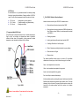
Figure 1. The VBA20
2.1 Sensor Connection
Fit the vibration sensor to the machine measurement position via a
magnetic base or stud. Connect the sensor cable to the BNC connector
on the meter. When a satisfactory sensor connection is made, the
sensor fault icon on the LCD display will disappear. Conversely, the
sensor fault icon will appear if the meter detects a poor sensor
connection.
2.2 Power On/Off
Power On - Push SEL key only for " sec. The meter defaults to the
overall vibration velocity range.
Power Off - Push two keys, SEL + BRG or SEL + VIB for 1 sec.
The meter will power-off on release of the keys.
The meter will automatically power-off after 3 minutes of no key
operation.
-4–
QM14 Issue 3
HS-620/630 User Guide
HS-620/630 User Guide
2.3 Key Functions
7 . Warranty
SEL keykey Press SEL to switch-on the meter.
In the Overall Vibration mode press SEL to toggle through the
measurement parameter options:options:
VIB key
-
All goods are guaranteed against defects in materials and workmanship,
subject to specific exclusions, for a period of 36 months from the date of
purchase. In the event of failure within 36 months of original purchase, the
company will promptly repair or replace the defective components without
charge.
Specific exceptions rendering the Warranty void are:If repair is attempted by unauthorised persons or agents, or if the product has
been used for purposes for which it was not intended and or subjected to
abuse or wilful neglect. No liability can be accepted for loss of items or
component parts. It is expected that the user takes sufficient precautions to
safeguard all guaranteed items.
Press VIB to toggle between Measure and Hold modes.
The Hold mode is indicated by an ’’H’ in the display.
In the BRG mode Press VIB to enter the Overall Vib.
mode.
BRG key -
In the Overall Vib. mode press BRG to enter the
Bearing Status mode.
In the Bearing Status measurement mode press BRG to
toggle between this and the Bearing Status Hold mode
indicated by an ‘H’’ on the display.
When the overall velocity reading is in the Hold mode, the meter display
indicates the vibration alarm status of the machine according to
ISO10816 as defined in section 3.
ISO10816-3
de the meter
When the BRG velocity or g reading is in the Hold mo
mode
-of-thumb
thumb
display indicates the bearing status according to a rule
rule-of-thumb
assessment as defined in section 4.
-5–
Q
M14 IIssue
ssue 3
QM14
Hansford Sensors Ltd.
Artisan, Hillbottom Road,
Sands Industrial Estate,
High Wycombe, Buckinghamshire
HP12 4HJ, England.
Tel: + 44 (0)845 680 1957
Fax: + 44 (0)845 680 1958
Web: www.hansfordsensors.com
- 14 –
QM14 Issue 3
HS-620/630 User Guide
HS-620/630 User Guide
2.4 Overall Vibration Measurement & Assessment
6
Specifications
Input...................... Constant Current Accelerometer 100mV/g
Vibration............... Acceleration: 0-20gPk, Frequency Range 5Hz-12kHz
Velocity:0-200mm/s RMS, Freq. Range 10Hz-1kHz
Automatic Alarm Check: ISO10816-3.
Displacement: 0-2000!m Peak-Peak,
Freq. Range 5Hz-1kHz
Bearing: ................ Bg: 0-20 g RMS Freq. Range 1kHz -12 kHz Applies to
Bg line & Bv line.
Bv: 0-200 mm/s RMS, Freq. Range 1kHz-12 kHz
Automatic Alarm Check for BG and BV:Rule-of-thumb
Temp. Range: ..... -20°C to 120°C or -5°F to +250°F (HS-630 only)
Laser Guide: ....... Red, $=650nm <1mW, IEC 60825-1 compliant
(HS-630 only)
Distance Range: .. For Temp. measurement 0 to2 metres (HS-630)
Accuracy: ............. +/-5%
Display:
LCD
At switch-on the meter defaults to the Velocity measurement mode, with
the units ‘mm/s rms’ indicated at the bottom right of the display.
If required, press SEL to select acceleration or displacement. Note that
no vibration assessment is available on these ranges.
When the vibration reading has settled, press VIB to move to the Hold
mode. An ‘H’ icon is displayed.
In the velocity range the meter will then indicate either a tick icon for OK,
a single bell for vibration alert or two bells for danger.
The meter makes this assessment depending on the vibration level and
one of the four machine group options selected using the SEL key.
The machine groups are defined in ISO10816-3 and the meter
categorises these as ’ISO1&3-R’, ‘ISO1&3-F’, ‘ISO2&4-R’, ‘ISO2&4-F’.
R and F refer to rigid and flexible machine mounting respectively.
A label on the back of the meter gives details of the ISO10816-3
machine groups. The user can refer to this to confirm the appropriate
group number for the tested machine. The information contained is as
follows in section 2.5.
2.5 ISO Machine Groups:
Power.................... Lithium rechargeable battery, 3.6V 1700 mAh,
Recharge time 3 hours, >48 hours continuous operation
Temperature......... Operation: -10°C to +50°C; Storage: -20°C to +60°C
Meter Sealing ....... IP54
Group 1 – Large machines rated power above 300KW; Electrical
machines with shaft dia. >315mm. Normally sleeve bearings, speed
120RPM - 15000RPM.
Group 2 – Medium size machines rated power 15KW < P 300KW;
Electrical machines with shaft 160mm <dia.>315mm. Normally element
bearings, Speed above 600RPM.
Spike Length........ 75mm
Magnetic Base ..... Diameter 25mm, H 17mm, pull strength 12Kg
Meter Size............. L 115mm x W 70mm x D 25mm
Group 3 – Pumps with multi-vane impeller and with separate driver
(centrifugal, mixed flow or axial flow) with rated power above 15KW.
Carry Case Size ... W 342mm x D 265mm x H 80mm
Group 4 – Pumps with multi-vane impeller and with integrated driver
(centrifugal, mixed flow or axial flow) with rated power above 15KW.
Weight .................. Full kit including carry case 1.25 Kgs
Support Class: R = Rigid Mount:
Cable Length........ 0.8m (other lengths available)
- 13 –
QM14 Issue 3
F = Flexible Mount.
-6–
QM14 Issue 3
HS-620/630 User Guide
2.6 Bearing Status Check
Fix the sensor directly to the bearing housing as close to the bearing as
possible. Note that valid high frequency readings are unlikely to be
measured using hand pressure and the spike.
Press the BRG key to enter the Bearing Status mode.
HS-620/630 User Guide
5.1. Surface Temperature Measurement
The temperature sensor measures the average temperature in a circle
of diameter one-eighth of the distance between the surface and the
sensor. For example, when the meter is held 1m from a surface, the
sensor will respond to a 125mm spot diameter on the surface. Thus, the
measuring distance will define the size surface to be measured. The
maximum recommended distance from surface to sensor is 2m and
hence the maximum spot diameter is 250mm. The measurement is
made as follows:-
Press the SEL key to select either Bg (g RMS) or Bv (mm/s RMS).
Switch on the meter using the SEL key
When the bearing status reading has settled, press the BRG key to
enter the hold mode (H). The bearing status reading is then held and the
rule-of-thumb alarm status displayed.
Press the F/°C for the temperature mode
Press the SEL key to toggle through and select the appropriate speed
range of the bearing shaft. (rpm:<500, rpm:<1000, rpm:<2000,
rpm:<5000, rpm:<10000) .
The meter will then indicate either a tick icon for OK, a single bell for
vibration alert or two bells for danger.
The meter makes the assessment based on the rules-of-thumb defined
in section 4
Aim the laser beam at the surface to be measured at a suitable distance
from the surface, remembering that the temperature sensor spot
diameter is one-eighth of the distance (ie not the laser spot size).
The temperature reading can be toggled between °F and °C using the
SEL key. Ambient temperature is indicated at the bottom left of the
display.
Exit the temperature mode by pressing the Vib or Brg key.
2.7 Battery & Charger
The Vibration Meter is powered by an internal rechargeable Lithium-Ion
battery which can operate for 48 hours continuously following full
charge. The battery condition is indicated by an icon at the top right of
the meter display.
The battery charger supplied requires 3 hours to fully charge the battery.
An LED on the charger indicates the charge status, being orange when
charging and green when charging is complete.
- 12 –
-7–
QM14 Issue 3
QM14 Issue 3
HS-620/630 User Guide
4.2 BV Values
Bv measurement is a long established method for detecting bearing
faults which gives reliable indication of bearing condition in 80-90% of
cases. The rule-of-thumb assessment used in the meter is as follows:!
!
!
BV # 1mm/s
BV =1-2mm/s
BV > 2mm/s
-
Healthy bearing, correctly greased
Possibly damaged or un-greased bearing
Bearing seizure likely
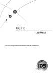
5 - Temperature Mode (HS-630 only)
The HS-630 uses a thermopile infra-red sensor to indicate temperature in
Deg.C or Deg.F on the display. An alignment laser beam is provided to
indicate the area where the temperature is being measured. Ambient
temperature is also indicated in the bottom left of the display.
HS-620/630 User Guide
3
The ISO10816-3 Machine Vibration Standard
Industrial machines covered by the ISO10816-3 standard include :!
Steam turbines with nominal power less than 50MW
!
Steam turbines with nominal power above 50MW with speeds less
than 1500rpm or above 3600rpm (ie. excludes machines included
in ISO10816-2
!
Rotating compressors
!
Industry gas turbines with nominal power less than 3MW
!
Centrifugal, Mixed flow, or Axial flow pumps
!
Electric Generators excluding Hydro-electric or pump stations
!
Electrical motors of all types
!
Blowers or fans
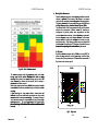
The standard classifies machine groups as in section 2.5 and defines
vibration levels for each group, shown in the chart on page 9, as follows:Green – levels expected for a new machine.
Yellow - levels considered as acceptable for long periods.
Amber - levels not acceptable for long periods.
Red – levels likely to cause machine damage.
Fig.4. HS-630
It further classifies machines as being either rigid or flexible mounted with the
flexible mounted machines being allowed higher vibration levels. The meter
indicates a tick box for levels in the green and yellow sections and uses the
lower limit for the amber sections and the red sections in its vibration
assessment.
Caution – Laser radiation - Do not stare into the Laser beam.
- 11 –
QM14 Issue 3
-8–
QM14 Issue 3
HS-620/630 User Guide
HS-620/630 User Guide
4
Bearing Status Assessment
Assessment
When the rolling elements move inside a bearing, broadband noise and
vibration is generated. This increases if the bearing is not properly
lubricated, or is overloaded due to misalignment or damaged surfaces.
The bearing vibration Bg or Bv measured by the meter is the RMS value
of all high frequency bearing vibrations between 1kHz and 12KHz.
The vibrations below 1kHz are suppressed in the Bg and Bv modes to
balance or
eliminate the measurement vibrations caused by im
imbalance
misalignment. A practical problem arises in gearboxes, and other
machines where steel meets steel, in which vibrations are produced in
the same frequency range as the bearing vibrations. For this reason
bearings should not normally be exchanged on the basis of a high
bearing value only. A high bearing condition value is an indication that
analyser will indicate if there are
further analysis is required
required,, and an FFT analyser
beari frequencies.
frequencies corresponding to the calculated bearing
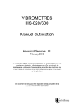
4.1 Bg Value
-12kHz
12kHz in unit
s of g RMS. The
Bg value is vibration acceleration within 1
1-12kHz
units
reason for using acceleration is that it gives larger values at higher
rule thumb assessment of
frequency than velocity measurement. The rule-ofrule-of-thumb
Bg is shown in the chart on page 10.
Fig.2 ISO 10816-3 Vibration Lev
Levels
els
lated to the basic
The machine mountings affect the resonances re
related
running speed of the machine. Machines with rubber or spring
mountings often vibrate at low speeds following start
-up, and as the
start-up,
speed increases the vibration level is reduced. Such a machine is
considered to be flexible mounted.
Modern high speed machines having flexible bearing supports can also
be considered as flexible mounted even though not mounted on rubber
or springs.
A great advantage of using proper vibration measurements and
standards is that future maintenance requirements and costs can be
assessed reliably on machine commissioning. For example, if levels of
3mm/s rms are measured for a new machine, it is likely to require high
maintenance activity. The specific requirement of this is dependant on
the machine design and the
the advice of the machine manufacturer should
be sought.
Fig.3.
-9–
Q
M14 IIssue
ssue 3
QM14
Levels
Bg Levels
- 10 –
Q
QM14
M14 IIssue
ssue 3