1
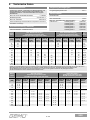
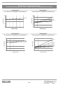
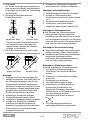
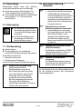
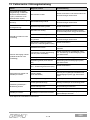
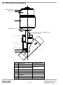
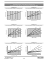
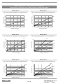
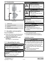
550 Schrägsitzventil Metall, DN 8 - 80 Angle Seat Globe Valve Metal, DN 8 - 80 DE ORIGINALBETRIEBSANLEITUNG GB OPERATING INSTRUCTIONS Antrieb 0 und 1 Actuator 0 and 1 Antrieb 2 bis 5 Actuator 2 to 5 550 Inhaltsverzeichnis 1 1 2 2.1 Voraussetzungen für die einwandfreie Funktion des GEMÜ-Ventils: Sachgerechter Transport und Lagerung. Installation und Inbetriebnahme durch eingewiesenes Fachpersonal. Bedienung gemäß dieser Betriebsanleitung. Ordnungsgemäße Instandhaltung. 2.2 2.3 3 4 5 6 7 8 8.1 8.2 8.3 8.4 9 9.1 10 11 11.1 11.2 11.3 11.4 12 12.1 12.2 12.3 13 14 15 16 17 18 19 20 21 Allgemeine Hinweise 2 Allgemeine Sicherheitshinweise 2 Hinweise für Service- und Bedienpersonal 3 Warnhinweise 3 Verwendete Symbole 4 Begriffsbestimmungen 4 Vorgesehener Einsatzbereich 4 Auslieferungszustand 4 Technische Daten 5 Bestelldaten 9 Herstellerangaben 10 Transport 10 Lieferung und Leistung 10 Lagerung 10 Benötigtes Werkzeug 10 Funktionsbeschreibung 10 Sonderentlüftung 10 Geräteaufbau 11 Montage und Bedienung 11 Montage des Ventils 11 Bedienung 13 Steuerfunktionen 13 Steuermedium anschließen 13 Montage / Demontage von Ersatzteilen 14 Demontage Antrieb und Dichtring 4 14 Auswechseln der Sitzdichtung 14 Montage Antrieb und Dichtring 4 14 Inbetriebnahme 15 Inspektion und Wartung 15 Demontage 16 Entsorgung 16 Rücksendung 16 Herstellererklärung / Hinweise 16 Fehlersuche / Störungsbehebung 17 Schnittbild und Ersatzteile 18 EG-Konformitätserklärung 19 Rücksendeerklärung 38 550 Allgemeine Hinweise Korrekte Montage, Bedienung und Wartung oder Reparatur gewährleisten einen störungsfreien Betrieb des Ventils. + 2 Beschreibungen und Instruktionen beziehen sich auf Standardausführungen. Für Sonderausführungen, die in dieser Betriebsanleitung nicht beschrieben sind, gelten die grundsätzlichen Angaben in dieser Betriebsanleitung in Verbindung mit einer zusätzlichen Sonderdokumentation. Allgemeine Sicherheitshinweise Die Sicherheitshinweise berücksichtigen nicht: Zufälligkeiten und Ereignisse, die bei Montage, Betrieb und Wartung auftreten können. die ortsbezogenen Sicherheitsbestimmungen, für deren Einhaltung - auch seitens des hinzugezogenen Montagepersonals - der Betreiber verantwortlich ist. 2 / 40 2.1 Hinweise für Serviceund Bedienpersonal 2.2 Die Betriebsanleitung enthält grundlegende Sicherheitshinweise, die bei Inbetriebnahme, Betrieb und Instandhaltung zu beachten sind. Nichtbeachtung kann zur Folge haben: Gefährdung von Personen durch elektrische, mechanische und chemische Einwirkungen. Gefährdung von Anlagen in der Umgebung. Versagen wichtiger Funktionen. Gefährdung der Umwelt durch Austreten gefährlicher Stoffe bei Leckage. Vor Inbetriebnahme: G Betriebsanleitung lesen. G Montage- und Betriebspersonal ausreichend schulen. G Sicherstellen, dass der Inhalt der Betriebsanleitung vom zuständigen Personal vollständig verstanden wird. G Verantwortungs- und Zuständigkeitsbereiche regeln. Warnhinweise Warnhinweise sind, soweit möglich, nach folgendem Schema gegliedert: SIGNALWORT Art und Quelle der Gefahr ® Mögliche Folgen bei Nichtbeachtung. G Maßnahmen zur Vermeidung der Gefahr. Warnhinweise sind dabei immer mit einem Signalwort und teilweise auch mit einem gefahrenspezifischen Symbol gekennzeichnet. Folgende Signalwörter bzw. Gefährdungsstufen werden eingesetzt: GEFAHR Unmittelbare Gefahr! ® Bei Nichtbeachtung sind Tod oder schwerste Verletzungen die Folge. WARNUNG Möglicherweise gefährliche Situation! ® Bei Nichtbeachtung drohen schwerste Verletzungen oder Tod. Bei Betrieb: G Betriebsanleitung am Einsatzort verfügbar halten. G Sicherheitshinweise beachten. G Nur entsprechend der Leistungsdaten betreiben. G Wartungsarbeiten und Reparaturen dürfen nur durch GEMÜ vorgenommen werden. VORSICHT Möglicherweise gefährliche Situation! ® Bei Nichtbeachtung drohen mittlere bis leichte Verletzungen. VORSICHT (OHNE SYMBOL) Möglicherweise gefährliche Situation! ® Bei Nichtbeachtung drohen Sachschäden. GEFAHR Sicherheitsdatenblätter bzw. die für die verwendeten Medien geltenden Sicherheitsvorschriften unbedingt beachten! Bei Unklarheiten: Bei nächstgelegener GEMÜVerkaufsniederlassung nachfragen. 3 / 40 550 2.3 Verwendete Symbole 4 Gefahr durch heiße Oberflächen! Gefahr durch ätzende Stoffe! + G ® 3 Hand: Beschreibt allgemeine Hinweise und Empfehlungen. Punkt: Beschreibt auszuführende Tätigkeiten. Pfeil: Beschreibt Reaktion(en) auf Tätigkeiten. Aufzählungszeichen Begriffsbestimmungen Betriebsmedium Medium, das durch das Ventil fließt. Vorgesehener Einsatzbereich Das 2/2-Wege-Ventil GEMÜ 550 ist für den Einsatz in Rohrleitungen konzipiert. Es steuert ein durchfließendes Medium indem es durch ein Steuermedium geschlossen oder geöffnet werden kann. Das Ventil ist geeignet für aggressive, neutrale, gasförmige und flüssige Medien, die die physikalischen und chemischen Eigenschaften des jeweiligen Gehäuse- und Dichtwerkstoffes nicht negativ beeinflussen. Die Betätigung erfolgt über einen Kolbenantrieb, der mit neutralen Gasen angesteuert wird. Das Ventil gemäß der technischen Daten einsetzen (siehe Kapitel 6 "Technische Daten"). Das Ventil ist bei hohen Betriebsmediumstemperaturen einsetzbar. Das Ventil kann einfach zum Regelventil erweitert werden. WARNUNG Steuermedium Medium mit dem durch Druckaufbau oder Druckabbau das Ventil angesteuert und betätigt wird. Ventil nur bestimmungsgemäß einsetzen! ® Sonst erlischt Herstellerhaftung und Gewährleistungsanspruch. G Das Ventil ausschließlich entsprechend den in der Vertragsdokumentation und Betriebsanleitung festgelegten Betriebsbedingungen verwenden. G Das Ventil darf nicht in explosionsgefährdeten Zonen, die in der Vertragsdokumentation nicht bestätigt sind, verwendet werden. Steuerfunktion Mögliche Betätigungsfunktionen des Ventils. 5 Auslieferungszustand Das GEMÜ-Ventil wird als separat verpacktes Bauteil ausgeliefert. 550 4 / 40 6 Technische Daten Durchflussmedium Umgebungsbedingungen Aggressive, neutrale, gasförmige und flüssige Medien, die die physikalischen und chemischen Eigenschaften des jeweiligen Gehäuse- und Dichtwerkstoffes nicht negativ beeinflussen. Umgebungstemperatur max. Max. zul. Druck des Betriebsmediums Neutrale Gase Medientemperatur Steuermedium s. Tabelle -10° bis 180° C Max. zul. Viskosität Max. Steuerdruck: 600 mm²/s Durchflussrichtung / Gewicht siehe Bestelldaten / Datenblatt Seite 4 [DN] 8 10 15 10 15 20 25 32 40 50 65 80 Antriebsgröße 0G Kolbenø 28 mm 10 10 10 - 8 bar Max. zul. Temperatur des Steuermediums: Füllvolumen Antriebsgröße 0: Antriebsgröße 1: Antriebsgröße 2: Antriebsgröße 3: Antriebsgröße 4: Antriebsgröße 5: weitere Ausführungen für tiefere/höhere Temperaturen und höhere Viskositäten auf Anfrage. Nennweite 60° C Max. Betriebsdruck [bar] Federkraft geschlossen (NC) Durchflussrichtung gegen den Teller Antriebs- Antriebs- Antriebs- Antriebsgröße 1G größe 2G größe 3G größe 4G KolbenKolbenKolbenKolbenø 42 mm ø 60 mm ø 80 mm ø 100 mm 15 11 25 6 15 25 8 16 25 5 10 18 6 12 3 7 - Antriebsgröße 5G Kolbenø 130 mm 25 20 15 10 8 80° C 0,006 dm³ 0,025 dm³ 0,084 dm³ 0,245 dm³ 0,437 dm³ 0,798 dm³ Max. Betriebsdruck [bar] KvFederkraft geschlossen (NC) Werte Durchflussrichtung mit dem Teller Antriebs- Antriebs- Antriebs- Antriebsgröße 0M größe 1M größe 2M größe 3M 3 KolbenKolbenKolbenKolben- [m /h] ø 28 mm ø 42 mm ø 60 mm ø 80 mm 10 2,1 10 2,4 10 2,4 10 4,5 10 10 5,4 10 10 10 10,0 10 10 15,2 10 23,0 10 41,0 10 68,0 95,0 130,0 Sämtliche Druckwerte sind in bar - Überdruck angegeben. Bei Anströmung des Ventils mit dem Teller (M) besteht bei flüssigen Medien die Gefahr von Schließschlägen! Es ist zu beachten, dass der Ventilkörper aus RG in Rohrleitungssystemen nach DIN nur bis max. PN 16 und Nirogusskörper bis PN 25 zugelassen sind. Kv-Werte ermittelt gemäß Norm IEC 534, Anschluss Gewindemuffe DIN ISO 228. Die Kv-Wertangaben beziehen sich auf die Steuerfunktion 1 (NC) und den größten Antrieb für die jeweilige Nennweite. Andere Kombinationen können abweichende Kv-Werte haben. Steuerdruck [bar] Federkraft geschlossen (NC) Durchflussrichtung mit Teller Steuerdruck [bar] Federkraft geschlossen (NC) Durchflussrichtung gegen den Teller Nennweite [DN] Antriebsgröße 0G Kolbenø 28 mm Antriebsgröße 1G Kolbenø 42 mm Antriebsgröße 2G Kolbenø 60 mm Antriebsgröße 3G Kolbenø 80 mm Antriebsgröße 4G Kolbenø 100 mm Antriebsgröße 5G Kolbenø 130 mm Antriebsgröße 0M Kolbenø 28 mm Antriebsgröße 1M Kolbenø 42 mm Antriebsgröße 2M Kolbenø 60 mm Antriebsgröße 3M Kolbenø 80 mm 8 10 15 10 15 20 25 32 40 50 65 80 4-8 4-8 4-8 - 4-8 4-8 4-8 - 4-8 4-8 4-8 4-8 - 4-8 4-8 4-8 4-8 4-8 - 4-8 4-8 4-8 4-8 - 5-8 5-8 5-8 5-8 5-8 5-8 5-8 5-8 - 5-8 5-8 5-8 - 5-8 5-8 5-8 - 5-8 5-8 5-8 5-8 5-8 - Höhere Steuerdrücke auf Anfrage. 5 / 40 550 Betriebsdruck- / Steuerdruckkennlinien Durchflussrichtung: mit dem Teller / Steuerfunktion: Federkraft geschlossen (NC) Antriebsgröße 0 Antriebsgröße 1 min. Steuerdruck in Abhängigkeit vom Betriebsdruck min. Steuerdruck in Abhängigkeit vom Betriebsdruck 6,0 6,0 5,0 DN8/10/15 Steuerdruck [bar] Steuerdruck [bar] Steuerdruck [bar] Steuerdruck [bar] 5,0 4,0 3,0 2,0 DN20 4,0 DN15 DN10/12 3,0 2,0 1,0 1,0 0,0 0,0 0 2 4 6 8 0 10 2 4 Betriebsdruck [bar] Betriebsdruck [bar] 6 8 10 Betriebsdruck [bar] Betriebsdruck [bar] Antriebsgröße 2 Antriebsgröße 3 min. Steuerdruck in Abhängigkeit vom Betriebsdruck min. Steuerdruck in Abhängigkeit vom Betriebsdruck 6,0 6,0 5,0 5,0 DN25 DN20 DN15 4,0 Steuerdruck Steuerdruck [bar] [bar] Steuerdruck [bar] Steuerdruck [bar] DN50 3,0 2,0 1,0 DN40 4,0 3,0 DN32 2,0 DN25 DN20 DN15 1,0 0,0 0,0 0 2 4 6 8 10 0 Betriebsdruck [bar] Betriebsdruck [bar] 550 2 4 6 Betriebsdruck [bar] Betriebsdruck [bar] 6 / 40 8 10 Betriebsdruck- / Steuerdruckkennlinien Durchflussrichtung: gegen den Teller / Steuerfunktion: Federkraft geöffnet (NO) Antriebsgröße 0 Antriebsgröße 1 min. Steuerdruck in Abhängigkeit vom Betriebsdruck min. Steuerdruck in Abhängigkeit vom Betriebsdruck 8,0 7,0 7,0 DN8/10/15 6,0 Steuerdruck [bar] Steuerdruck [bar] Steuerdruck [bar] Steuerdruck [bar] DN20 8,0 5,0 4,0 3,0 2,0 1,0 6,0 DN15 5,0 DN10/12 4,0 3,0 2,0 1,0 0,0 0,0 0 5 10 15 20 0 25 5 10 Betriebsdruck [bar] Betriebsdruck [bar] 15 20 25 Betriebsdruck [bar] Betriebsdruck [bar] Antriebsgröße 2 Antriebsgröße 3 min. Steuerdruck in Abhängigkeit vom Betriebsdruck min. Steuerdruck in Abhängigkeit vom Betriebsdruck DN32 8,0 5,0 DN20 4,0 3,0 DN40 7,0 DN25 6,0 Steuerdruck [bar] Steuerdruck [bar] Steuerdruck [bar] Steuerdruck [bar] 7,0 DN50 8,0 DN15 2,0 6,0 DN32 5,0 4,0 DN25 3,0 DN20 2,0 1,0 1,0 0,0 0,0 0 5 10 15 20 25 0 5 10 15 20 25 Betriebsdruck [bar] Betriebsdruck [bar] Betriebsdruck [bar] Betriebsdruck [bar] Antriebsgröße 4 Antriebsgröße 5 min. Steuerdruck in Abhängigkeit vom Betriebsdruck min. Steuerdruck in Abhängigkeit vom Betriebsdruck 7,0 7,0 6,0 6,0 DN40 5,0 4,0 DN32 3,0 DN15 DN80 8,0 DN50 Steuerdruck [bar] Steuerdruck [bar] Steuerdruck [bar] Steuerdruck [bar] 8,0 2,0 DN65 5,0 DN50 4,0 DN40 3,0 DN32 2,0 1,0 1,0 0,0 0,0 0 5 10 15 20 0 25 Betriebsdruck [bar] Betriebsdruck [bar] 5 10 15 20 25 Betriebsdruck [bar] Betriebsdruck [bar] 7 / 40 550 Antriebsgröße 0 Antriebsgröße 1 min. Steuerdruck in Abhängigkeit vom Betriebsdruck min. Steuerdruck in Abhängigkeit vom Betriebsdruck 8,0 8,0 7,0 7,0 6,0 6,0 5,0 Steuerdruck [bar] Steuerdruck [bar] Steuerdruck[bar] [bar] Steuerdruck Betriebsdruck- / Steuerdruckkennlinien Durchflussrichtung: gegen den Teller / Steuerfunktion: Beidseitig angesteuert (DA) DN8/10/15 4,0 3,0 2,0 1,0 DN20 5,0 DN15 4,0 DN10/12 3,0 2,0 1,0 0,0 0,0 0 5 10 15 20 25 0 5 Betriebsdruck [bar] Betriebsdruck [bar] 10 15 20 25 Betriebsdruck [bar] Betriebsdruck [bar] Antriebsgröße 2 Antriebsgröße 3 min. Steuerdruck in Abhängigkeit vom Betriebsdruck min. Steuerdruck in Abhängigkeit vom Betriebsdruck DN32 8,0 6,0 Steuerdruck Steuerdruck[bar] [bar] Steuerdruck [bar] Steuerdruck [bar] DN40 7,0 7,0 DN25 5,0 4,0 DN20 3,0 DN15 2,0 1,0 0,0 DN50 8,0 6,0 5,0 DN32 4,0 DN25 3,0 DN20 2,0 1,0 0 5 10 15 Betriebsdruck [bar] Betriebsdruck [bar] 20 0,0 25 0 5 10 15 20 25 Betriebsdruck [bar] Betriebsdruck [bar] Antriebsgröße 4 Antriebsgröße 5 min. Steuerdruck in Abhängigkeit vom Betriebsdruck min. Steuerdruck in Abhängigkeit vom Betriebsdruck DN50 7,0 7,0 6,0 5,0 Steuerdruck [bar] Steuerdruck [bar] Steuerdruck [bar] Steuerdruck [bar] DN80 8,0 8,0 DN40 4,0 DN32 3,0 DN15 2,0 DN65 6,0 5,0 DN50 4,0 3,0 DN40 2,0 DN32 1,0 1,0 0,0 0,0 0 5 10 15 20 0 25 550 5 10 15 Betriebsdruck [bar] Betriebsdruck [bar] Betriebsdruck [bar] Betriebsdruck [bar] 8 / 40 20 25 7 Bestelldaten Gehäuseform Code Durchgangskörper D Anschlussart Steuerfunktion Code Schweißstutzen Stutzen DIN Stutzen DIN 11850, Reihe 1 Stutzen DIN 11850, Reihe 2 Stutzen DIN 11850, Reihe 3 Stutzen SMS 3008 Stutzen ASME BPE Stutzen EN ISO 1127 Schraubverbindungen Gewindemuffe DIN ISO 228 Gewindemuffe BS 21 Rc Gewindestutzen DIN ISO 228 Gewindemuffe NPT Flansch Flansch EN 1092 / PN16 / Form B Baulänge EN 558-1, Reihe 1 ISO 5752, basic series 1 Flansch EN 1092 / PN25 / Form B Baulänge EN 558-1, Reihe 1 Clamp-Stutzen Clamp in Anlehnung an ASME BPE für Rohr EN ISO 1127, Baulänge EN 558-1, Reihe 1 Clamp DIN 32676 für Rohr DIN 11850, Baulänge EN 558-1, Reihe 1 Clamp ASME BPE für Rohr ASME BPE, Baulänge EN 558-1, Reihe 1 0 16 17 18 37 59 60 Code Federkraft geschlossen (NC) 1 Federkraft geöffnet (NO) 2 Beidseitig angesteuert (DA) 3 Beidseitig angesteuert (nur für Regelventile) (in Ruhestellung geöffnet) 8 Antriebsgröße 1 3B 9 31 Code Antrieb 0 Kolben ø 28 mm 0 Antrieb 1 Kolben ø 42 mm 1 Antrieb 2 Kolben ø 60 mm 2 Antrieb 3 Kolben ø 80 mm 3 Antrieb 4 Kolben ø 100 mm 4 Antrieb 5 Kolben ø 130 mm 5 Durchflussrichtung 8 Code Gegen den Teller G Mit dem Teller M 10 G* M 82 86 88 Ventilkörperwerkstoff Code 1.4435 (ASTM A 351 CF3M) Feinguss* 34 1.4408 Edelstahl-Guss 37 1.4435 (316 L) Schmiedekörper 40 ASTM A 351 CF3M Feinguss* C1 * Zu bevorzugende Durchflussrichtung bei inkompressiblen, flüssigen Medien um „Wasserschläge“ zu vermeiden Federsatz Standard Code PTFE 5 PTFE mit Glasverstärkung 1 Sonderausführungen * Material ist gleichwertig 316L Sitzdichtung Code 5G Code Oberflächen, elektropoliert ist standardmäßig trovaliert 1781 Sonderentlüftung* speziell für Lebensmittel-Industrie 6996 * Option 6996 kann nur ab Werk geliefert werden. Bestellbeispiel 550 Typ 550 Nennweite Gehäuseform (Code) Anschlussart (Code) Ventilkörperwerkstoff (Code) Sitzdichtung (Code) Steuerfunktion (Code) Antriebsgröße (Code) Durchflussrichtung (Code) Federsatz (Code) 15 D 1 34 5 1 1 G 1 1781 15 D 1 34 5 1 1 G 1 Sonderausführungen (Code) 1781 9 / 40 550 8 Herstellerangaben 8.1 G G G G G Transport Ventil nur auf geeignetem Lademittel transportieren, nicht stürzen, vorsichtig handhaben. Verpackungsmaterial entsprechend den Entsorgungsvorschriften / Umweltschutzbestimmungen entsorgen. 8.2 G Lieferung und Leistung Ware unverzüglich bei Erhalt auf Vollständigkeit und Unversehrtheit überprüfen. Lieferumfang aus Versandpapieren, Ausführung aus Bestellnummer ersichtlich. Das Ventil wird im Werk auf Funktion geprüft. Auslieferungszustand des Ventils: Steuerfunktion: 1 Federkraft geschlossen (NC) 2 Federkraft geöffnet (NO) 3 Beidseitig angesteuert (DA) 8 Beidseitig angesteuert (in Ruhestellung geöffnet) 8.3 G G G G Zustand: geschlossen geöffnet undefiniert geöffnet Lagerung Ventil staubgeschützt und trocken in Originalverpackung lagern. UV-Strahlung und direkte Sonneneinstrahlung vermeiden. Maximale Lagertemperatur: 60° C. 8.4 G 9 Das fremdgesteuerte 2/2 Wege-Ventil GEMÜ 550 ist ein Metall-Schrägsitzventil mit Durchgangskörper und besitzt einen Kolbenantrieb. Die Ventilkörper sind gemäß Datenblatt in verschiedenen Ausführungen erhältlich. Das Ventil hat bei Steuerfunktion NC serienmäßig eine optische Stellungsanzeige (für Steuerfunktion NO und DA auf Anfrage). Vielfältiges Zubehör ist lieferbar z.B. elektrische Stellungsrückmelder, Hubbegrenzung, elektropneumatische Stellungs- und Prozessregler. Die Absperrung am Ventilsitz erfolgt durch eine in den Ventilteller gekammerte PTFEDichtung. Die Abdichtung der Ventilspindel erfolgt über eine sich selbstnachstellende Stopfbuchsenpackung; dadurch ist auch nach langer Betriebszeit eine wartungsarme und zuverlässige Ventilspindelabdichtung gegeben. Der Abstreifring vor der Stopfbuchsenpackung schützt die Dichtung zusätzlich vor Verschmutzung und Beschädigung. 9.1 Sonderentlüftung Die Sonderentlüftung mit einem LippenRückschlagventil wurde u.a. für die Lebensmittel-Industrie entworfen. Sie verhindert das Eindringen von Schmutzwasser und Reinigungsmedien. Die Sonderentlüftung ist optional ab Werk verfügbar (siehe Bestelldaten Rubrik "Sonderausführungen"). Benötigtes Werkzeug Benötigtes Werkzeug für Einbau und Montage ist nicht im Lieferumfang enthalten. Passendes, funktionsfähiges und sicheres Werkzeug benutzen. 550 Funktionsbeschreibung 10 / 40 10 Geräteaufbau WARNUNG Aggressive Chemikalien! ® Verätzungen! G Montage nur mit geeigneter Schutzausrüstung. 4 3 VORSICHT Heiße Anlagenteile! ® Verbrennungen! G Nur an abgekühlter Anlage arbeiten. VORSICHT Ventil nicht als Trittstufe oder Aufstiegshilfe benutzen! ® Gefahr des Abrutschens / der Beschädigung des Ventils. Geräteaufbau 1 Ventilkörper 2 Steuerluftanschluss 3 Antrieb 4 Optische Stellungsanzeige VORSICHT Maximal zulässigen Druck nicht überschreiten! ® Eventuell auftretende Druckstöße (Wasserschläge) durch Schutzmaßnahmen vermeiden. 11 Montage und Anschluss G Vor Einbau: G Ventilkörperwerkstoff und Sitzdichtung entsprechend Betriebsmedium auslegen. G Eignung vor Einbau prüfen! Siehe Kapitel 6 "Technische Daten". G Installationsort: VORSICHT 11.1 Montage des Ventils WARNUNG Unter Druck stehende Armaturen! ® Gefahr von schwersten Verletzungen oder Tod! G Nur an druckloser Anlage arbeiten. G G G WARNUNG Haube steht unter Federdruck! ® Gefahr von schwersten Verletzungen oder Tod! G Antrieb nicht öffnen. Montagearbeiten nur durch geschultes Fachpersonal. Geeignete Schutzausrüstung gemäß den Regelungen des Anlagenbetreibers berücksichtigen. G 11 / 40 Ventil äußerlich nicht stark beanspruchen. Installationsort so wählen, dass Ventil nicht als Steighilfe genutzt werden kann. Rohrleitung so legen, dass Schub- und Biegungskräfte, sowie Vibrationen und Spannungen vom Ventilkörper ferngehalten werden. Ventil nur zwischen zueinander passenden, fluchtenden Rohrleitungen montieren. 550 Einbaulage: Für Ventile mit Regelkegel empfehlen wir eine senkrecht stehende oder hängende Einbaulage des Antriebs zur Optimierung der Standzeit. Richtung des Betriebsmediums: Durchflussrichtung: 6. Anlage bzw. Anlagenteil fachgerecht dekontaminieren, spülen und belüften. Montage bei Schweißstutzen: 1. Schweißtechnische Normen einhalten! 2. Antrieb vor Einschweißen des Ventilkörpers demontieren (siehe Kapitel 12.1). 3. Schweißstutzen abkühlen lassen. 4. Ventilkörper und Antrieb wieder zusammen bauen (siehe Kapitel 12.3). Montage bei Clampanschluss: Bei Montage der Clampanschlüsse entsprechende Dichtung zwischen Ventilkörper und Rohranschluss einlegen und mit Klammer verbinden. Die Dichtung sowie die Klammer der Clampanschlüsse sind nicht im Lieferumfang enthalten. G G* gegen den Teller* M mit dem Teller * Zu bevorzugende Durchflussrichtung bei inkompressiblen, flüssigen und dampfförmigen Medien um "Wasserschläge" zu vermeiden. Die Durchflussrichtung ist durch einen Pfeil auf dem Ventilkörper gekennzeichnet: gegen den Teller mit dem Teller Montage: 1. Eignung des Ventils für jeweiligen Einsatzfall sicherstellen. Das Ventil muss für die Betriebsbedingungen des Rohrleitungssystems (Medium, Mediumskonzentration, Temperatur und Druck) sowie die jeweiligen Umgebungsbedingungen geeignet sein. Technische Daten des Ventils und der Werkstoffe prüfen. 2. Anlage bzw. Anlagenteil stilllegen. 3. Gegen Wiedereinschalten sichern. 4. Anlage bzw. Anlagenteil drucklos schalten. 5. Anlage bzw. Anlagenteil vollständig entleeren und abkühlen lassen bis Verdampfungstemperatur des Mediums unterschritten ist und Verbrühungen ausgeschlossen sind. 550 Montage bei Schraubverbindung: G Schraubverbindungen entsprechend der gültigen Normen in Rohr einschrauben. G Ventilkörper an Rohrleitung anschrauben, geeignetes Gewindedichtmittel verwenden. Das Gewindedichtmittel ist nicht im Lieferumfang enthalten. Montage bei Flanschanschluss: Ventil im angelieferten Zustand einbauen: 1. Auf saubere und unbeschädigte Dichtflächen der Anschlussflansche achten. 2. Flansche vor Verschrauben sorgfältig ausrichten. 3. Dichtungen gut zentrieren. 4. Alle Flanschbohrungen nutzen. 5. Ventilflansch und Rohrflansch mit geeignetem Dichtmaterial und passenden Schrauben verbinden (Dichtmaterial und Schrauben sind nicht im Lieferumfang enthalten). Schrauben über Kreuz anziehen! 6. Nur Verbindungselemente aus zulässigen Werkstoffen verwenden! 12 / 40 Entsprechende Vorschriften schlüsse beachten! für An- Nach der Montage: G Alle Sicherheits- und Schutzeinrichtungen wieder anbringen bzw. in Funktion setzen. 11.2 Bedienung Nur für Regelventile: Steuerfunktion 8 Beidseitig angesteuert (in Ruhestellung geöffnet): Ruhezustand des Ventils: durch Federkraft geöffnet. Öffnen und Schließen des Ventils durch ansteuern der entsprechenden Steuerluftanschlüsse (Anschluss 2: Öffnen / Anschluss 4: Schließen). Optische Stellungsanzeige Anschluss 2 Ventil offen Steuerfunktion 1 Ventil geschlossen 11.3 Steuerfunktionen Anschluss 4 Folgende Steuerfunktionen sind verfügbar: Steuerfunktion 1 Federkraft geschlossen (NC): Anschluss 2 Ruhezustand des Ventils: durch Federkraft geschlossen. Ansteuern des Antriebs (Anschluss 2) öffnet das Ventil. Entlüften des Antriebs bewirkt das Schließen des Ventils durch Federkraft. Steuerfunktion 2, 3, 8 Steuerfunktion Steuerfunktion 2 Federkraft geöffnet (NO): Ruhezustand des Ventils: durch Federkraft geöffnet. Ansteuern des Antriebs (Anschluss 4) schließt das Ventil. Entlüften des Antriebs bewirkt das Öffnen des Ventils durch Federkraft. Steuerfunktion 3 Beidseitig angesteuert (DA): Anschlüsse 2 4 1 (NC) + - 2 (NO) - + 3 (DA) + + 8 (in Ruhestellung geöffnet) + + + = vorhanden / - = nicht vorhanden (Anschlüsse 2 / 4 siehe Bilder oben) 11.4 Steuermedium anschließen Ruhezustand des Ventils: keine definierte Grundposition. Öffnen und Schließen des Ventils durch ansteuern der entsprechenden Steuerluftanschlüsse (Anschluss 2: Öffnen / Anschluss 4: Schließen). + 13 / 40 Wichtig: Steuerluftleitungen spannungsund knickfrei montieren! Je nach Anwendung geeignete Anschlussstücke verwenden. 550 12.2 Auswechseln der Sitzdichtung Gewinde der Steuerluftanschlüsse 2 und 4: Antriebsgröße Gewinde 0 M5 1, 2 G 1/8 3, 4, 5 G 1/4 Steuerfunktion 1. Antrieb A demontieren wie in Kapitel 12.1, Punkte 1-4 beschrieben. 2. Antrieb A in Offen-Position bringen. 3. Mutter d an der Spindel b lösen (Spindel b mit geeignetem Werkzeug, das die Spindeloberfläche nicht beschädigt, festhalten). Scheibe e und Sitzdichtung 14 entnehmen. 4. Alle Teile reinigen,dabei nicht zerkratzen oder beschädigen. 5. Neue Sitzdichtung 14 einlegen. 6. Scheibe e einlegen. 7. Geeignetes Schraubensicherungsmittel auf Gewinde von Spindel b auftragen. 8. Antrieb A in Offen-Position bringen. 9. Mit Mutter d fixieren (Spindel b mit geeignetem Werkzeug, das die Spindeloberfläche nicht beschädigt, festhalten). 10. Antrieb A montieren wie in Kapitel 12.3, Punkt 1-5 beschrieben. Anschluss 1 Federkraft geschlossen (NC) 2: Steuermedium (Öffnen) 2 Federkraft geöffnet (NO) 4: Steuermedium (Schließen) 3 Beidseitig angesteuert (DA) 2: Steuermedium (Öffnen) 4: Steuermedium (Schließen) 8 Beidseitig angesteuert (in Ruhestellung geöffnet) 2: Steuermedium (Öffnen) 4: Steuermedium (Schließen) Anschlüsse 2 / 4 siehe Bilder Seite 13 12 Montage / Demontage von Ersatzteilen Siehe auch Kapitel 11.1 "Montage des Ventils" und Kapitel 20 "Schnittbild und Ersatzteile". 12.1 Demontage Antrieb und Dichtring 4 1. Antrieb A in Offen-Position bringen. 2. Überwurfmutter a lösen. 3. Antrieb A vom Ventilkörper 1 demontieren. 4. Dichtring 4 entnehmen. 5. Antrieb A in Geschlossen-Position bringen. + Wichtig: Nach Demontage alle Teile von Verschmutzungen reinigen (Teile dabei nicht beschädigen). Teile auf Beschädigung prüfen, ggf. auswechseln (nur Originalteile von GEMÜ verwenden). 12.3 Montage Antrieb und Dichtring 4 1. Antrieb A in Offen-Position bringen. 2. Neuen Dichtring 4 in Ventilkörper 1 einlegen. 3. Antrieb 360° drehbar. Position der Steuerluftanschlüsse beliebig. 4. Antrieb A auf Ventilkörper 1 ca. 90° vor Endposition der Steuerluftanschlüsse aufsetzen und mit Überwurfmutter a handfest anschrauben. 5. Überwurfmutter a mit Gabelschlüssel festschrauben (Drehmomente siehe Tabelle auf nächster Seite). Dabei dreht sich der Antrieb ca. 90° im Uhrzeigersinn bis zur gewünschten Position. 6. Antrieb A in Geschlossen-Position bringen, komplett montiertes Ventil auf Funktion und auf Dichtheit prüfen. + 550 14 / 40 Wichtig: Dichtring 4 bei jeder Demontage / Montage des Antriebs austauschen. Nennweite Antriebsgröße Drehmomente [Nm] DN 8 0G / 0M 35 DN 10 0G / 0M 35 DN 15 0G / 0M 35 DN 10 1G / 1M 90 DN 15 1G / 1M / 2G / 2M 90 DN 20 1G / 1M / 2G / 2M / 3G / 3M 100 DN 25 2G / 2M / 3G / 3M / 4G 120 DN 32 2G / 3G / 3M / 4G / 5G 120 DN 40 3G / 3M / 4G / 5G 150 DN 50 3G / 3M / 4G / 5G 200 DN 65 5G 260 DN 80 5G 280 14 Inspektion und Wartung WARNUNG Unter Druck stehende Armaturen! ® Gefahr von schwersten Verletzungen oder Tod! G Nur an druckloser Anlage arbeiten. VORSICHT Heiße Anlagenteile! ® Verbrennungen! G Nur an abgekühlter Anlage arbeiten. VORSICHT G G 13 Inbetriebnahme WARNUNG Aggressive Chemikalien! ® Verätzungen! G Vor Inbetriebnahme Dichtheit der Medienanschlüsse prüfen! G Dichtheitsprüfung nur mit geeigneter Schutzausrüstung. G Wartungs- und Instandhaltungstätigkeiten nur durch geschultes Fachpersonal. Für Schäden welche durch unsachgemäße Handhabung oder Fremdeinwirkung entstehen, übernimmt GEMÜ keinerlei Haftung. Nehmen Sie im Zweifelsfall vor Inbetriebnahme Kontakt mit GEMÜ auf. 1. Geeignete Schutzausrüstung gemäß den Regelungen des Anlagenbetreibers berücksichtigen. 2. Anlage bzw. Anlagenteil stilllegen. 3. Gegen Wiedereinschalten sichern. 4. Anlage bzw. Anlagenteil drucklos schalten. VORSICHT Gegen Leckage vorbeugen! G Schutzmaßnahmen gegen Überschreitung des maximal zulässigen Drucks durch eventuelle Druckstöße (Wasserschläge) vorsehen. Der Betreiber muss regelmäßige Sichtkontrollen der Ventile entsprechend den Einsatzbedingungen und des Gefährdungspotenzials zur Vorbeugung von Undichtheit und Beschädigungen durchführen. Ebenso muss das Ventil in entsprechenden Intervallen demontiert und auf Verschleiß geprüft werden (siehe Kapitel 12 "Montage / Demontage von Ersatzteilen"). Vor Reinigung bzw. vor Inbetriebnahme der Anlage: G Ventil auf Dichtheit und Funktion prüfen (Ventil schließen und wieder öffnen). G Bei neuen Anlagen Leitungssystem bei voll geöffnetem Ventil spülen (zum Entfernen schädlicher Fremdstoffe). + Reinigung: Betreiber der Anlage ist verantwortlich für Auswahl des Reinigungsmediums und Durchführung des Verfahrens. 15 / 40 Wichtig: Wartung und Service: Dichtungen setzen sich im Laufe der Zeit. Nach Montage / Demontage des Ventils Überwurfmutter auf festen Sitz überprüfen und ggf. nachziehen. 550 15 Demontage Demontage erfolgt unter den gleichen Vorsichtsmaßnahmen wie die Montage. G Ventil demontieren (siehe Kapitel 12.1 "Demontage Antrieb und Dichtring 4"). G Leitung des Steuermediums abschrauben (siehe Kapitel 11.3 "Steuermedium anschließen"). 16 Entsorgung G G Alle Ventilteile entsprechend den Entsorgungsvorschriften / Umweltschutzbedingungen entsorgen. Auf Restanhaftungen und Ausgasung von eindiffundierten Medien achten. 17 Rücksendung G G Ventil reinigen. Rücksendung nur mit vollständig ausgefüllter Rücksendeerklärung (anbei). Ansonsten erfolgt keine Gutschrift bzw. keine Erledigung der Reparatur sondern eine kostenpflichtige Entsorgung. + Hinweis zur Rücksendung: Aufgrund gesetzlicher Bestimmungen zum Schutz der Umwelt und des Personals ist es erforderlich, dass Sie die Erklärung (anbei) vollständig ausgefüllt und unterschrieben den Versandpapieren beilegen. Nur wenn diese Erklärung vollständig ausgefüllt ist, wird Ihre Rücksendung bearbeitet! 550 18 Herstellererklärung / Hinweise + Herstellererklärung: Gemäß EG-Maschinenrichtlinie 2006/42/EG gilt dieses Ventil nicht als Maschine, kann jedoch in eine als Maschine geltende Installation eingebaut werden. In diesem Fall den nachfolgenden Hinweis beachten. + Beim Einbau in eine als Maschine geltende Installation: Inbetriebnahme ist untersagt, bis festgestellt wurde, dass die Maschine (Anlage), in die dieses Ventil eingebaut wird, den Bestimmungen der EGMaschinenrichtlinie 2006/42/EG entspricht. + Hinweis zur Richtlinie 94/9/EG (ATEX Richtlinie): Ein Beiblatt zur Richtlinie 94/9/EG liegt dem Produkt bei, sofern es gemäß ATEX bestellt wurde. + Hinweis zur Mitarbeiterschulung: Zur Mitarbeiterschulung nehmen Sie bitte über die Adresse auf der letzten Seite Kontakt auf. Im Zweifelsfall oder bei Missverständnissen ist die deutsche Version des Dokuments ausschlaggebend! 16 / 40 19 Fehlersuche / Störungsbehebung Fehler Möglicher Grund Fehlerbehebung Luft entweicht aus Entlüftungsbohrung* im Antriebsdeckel bei Steuerfunktion 1 (NC) / Anschluss 2* bei Steuerfunktion 2 (NO) Steuerkolben undicht Antrieb austauschen und Steuermedium auf Verschmutzungen untersuchen Luft entweicht aus Leckagebohrung* Spindelabdichtung undicht Antrieb austauschen und Steuermedium auf Verschmutzungen untersuchen Medium entweicht aus Leckagebohrung* Stopfbuchsenpackung defekt Antrieb austauschen Steuerdruck zu niedrig Steuerdruck gemäß Datenblatt einstellen. Vorsteuerventil prüfen und ggf. austauschen Steuermedium nicht angeschlossen Steuermedium anschließen Steuerkolben bzw. Spindelabdichtung undicht Antrieb austauschen und Steuermedium auf Verschmutzungen untersuchen Antriebsfeder defekt (bei Steuerfunktion 2, Federkraft geöffnet (NO)) Antrieb austauschen Betriebsdruck zu hoch Ventil mit Betriebsdruck laut Datenblatt betreiben Fremdkörper zwischen Sitzdichtung und Sitz (siehe Schnittbild) Antrieb demontieren, Fremdkörper entfernen, Sitzdichtung auf Beschädigung prüfen, ggf. austauschen Ventilkörper undicht bzw. beschädigt Ventilkörper überprüfen, ggf. austauschen Sitzdichtung defekt (siehe Schnittbild) Sitzdichtung auf Beschädigungen prüfen, ggf. austauschen Antriebsfeder defekt (bei Steuerfunktion 1, Federkraft geschlossen (NC)) Antrieb austauschen Überwurfmutter lose Überwurfmutter nachziehen Dichtring defekt (siehe Schnittbild) Dichtring und zugehörige Dichtflächen auf Beschädigungen prüfen, ggf. Teile austauschen Ventilkörper beschädigt Ventilkörper tauschen Unsachgemäße Montage Montage Ventilkörper in Rohrleitung prüfen Verschraubungen lose Verschraubungen festziehen Dichtmittel defekt Dichtmittel ersetzen Ventilkörper undicht oder korrodiert Ventilkörper auf Beschädigungen prüfen, ggf. Ventilkörper tauschen Ventil öffnet nicht bzw. nicht vollständig Ventil im Durchgang undicht (schließt nicht bzw. nicht vollständig) Ventil zwischen Antrieb und Ventilkörper undicht Verbindung Ventilkörper Rohrleitung undicht Ventilkörper undicht * siehe Kapitel 20 "Schnittbild und Ersatzteile" 17 / 40 550 20 Schnittbild und Ersatzteile Entlüftungsbohrung Anschluss 4 A Anschluss 2 Leckagebohrung a 4 b c 14 e d 550 1 Pos. Benennung Bestellbezeichnung 1 Ventilkörper K 500... 4 Dichtring 14 Sitzdichtung A Antrieb a Überwurfmutter - b Spindel - c Ventilteller - d Mutter - e Scheibe - } 550...SVS... 9550 18 / 40 21 EG-Konformitätserklärung Konformitätserklärung Gemäß Anhang VII der Richtlinie 97/23/EG Wir, die Firma GEMÜ Gebr. Müller GmbH & Co. KG Fritz-Müller-Straße 6-8 D-74653 Ingelfingen erklären, dass unten aufgeführte Armaturen die Sicherheitsanforderungen der Druckgeräterichtlinie 97/23/EG erfüllen. Benennung der Armaturen - Typenbezeichnung Sitzventil GEMÜ 550 Benannte Stelle: TÜV Rheinland Berlin Brandenburg Nummer: 0035 Zertifikat-Nr.: 01 202 926/Q-02 0036 Konformitätsbewertungsverfahren: Modul H Armaturen DN ≤ 25 unterliegen der Druckgeräterichtlinie 97/23/EG Art. 3 §3. Sie werden nicht mit einem CE-Zeichen bezogen auf die Druckgeräterichtlinie 97/23/EG gekennzeichnet und es wird keine Konformität erklärt. Geschäftsleitung UNTERNEHMENSBEREICH VENTIL-, MESS- UND REGELSYSTEME GEMÜ Gebr. Müller Apparatebau GmbH & Co. KG · Fritz-Müller-Str. 6-8 · D-74653 Ingelfingen-Criesbach Telefon +49(0)7940/123-0 · Telefax +49(0)7940/123-192 · [email protected] · www.gemue.de 19 / 40 550 Contents 1 2 2.1 2.2 2.3 3 4 5 6 7 8 8.1 8.2 8.3 8.4 9 9.1 10 11 11.1 11.2 11.3 11.4 12 12.1 12.2 12.3 13 14 15 16 17 18 19 20 21 General notes General safety notes Notes for servicing and operating personnel Warning notes Symbols used Definition of terms Envisaged operational area Delivery condition Technical data Order data Manufacturer’s information Transport Delivery and performance Storage Tools needed Function description Special venting Construction Assembly and operation Assembling the valve Operation Control functions Connecting the control medium Assembly / disassembly of spare parts Disassembly of actuator and gasket 4 Replacement of seat seal Assembly of actuator and gasket 4 Commissioning Inspection and servicing Disassembly Disposal Returns Manufacturer’s declaration / information Troubleshooting / Fault clearance Sectional drawing and spare parts EC Declaration of conformity Goods return declaration 550 1 20 20 21 21 22 22 22 22 23 27 28 28 28 28 28 28 28 29 29 29 31 31 31 32 32 32 General notes Prerequisites for the correct functioning of the GEMÜ valve: Proper transport and storage Installation and commissioning by trained specialist staff Operation according to these operating instructions. Correct maintenance Correct assembly, operation, servicing and repair work ensure faultless valve operation. + 2 The descriptions and instructions apply to the standard versions. For special versions not described in these operating instructions the basic information contained herein applies in combination with an additional special documentation. General safety notes The safety notes do not take into account: Coincidences and events, which may occur during assembly, operation and servicing. Local safety regulations which must be adhered to by the operator - also with respect to any additional assembly personnel 32 33 33 34 34 34 34 35 36 37 39 20 / 40 2.1 Notes for servicing and operating personnel 2.2 The operating instructions contain fundamental safety notes that must be observed during commissioning, operation, and maintenance. Non-observance can cause: Prior to commissioning G Read the operating instructions. G Provide adequate training for the assembly and operating personnel. G Ensure that the contents of the operating instructions have been fully understood by the responsible personnel. G Define the areas of responsibility. During operation G Keep the operating instructions available at the place of use. G Observe the safety notes. G Use only in accordance with the operational data. G Any servicing work and repairs may only be performed by GEMÜ. Strictly observe the safety data sheets or the safety regulations valid for the media used. In case of uncertainty Consult the nearest GEMÜ sales office. Wherever possible, warning notes are organised according to the following scheme: SIGNAL WORD Type and source of the danger ® Possible consequences of non-observance. G Measures for avoiding danger. Personal hazard due to electrical, mechanical and chemical effects. Hazard to nearby equipment. Failure of important functions. Hazard to the environment due to the leakage of dangerous materials. DANGER Warning notes Warning notes are always marked with a signal word and sometimes also with a symbol for the specific danger. The following signal words and danger levels are used: DANGER Imminent danger! ® Non-observance will lead to death or severe injury. WARNING A possibly dangerous situation! ® Non-observance can cause death or severe injury. CAUTION A possibly dangerous situation! ® Non-observance can cause medium to light injury. CAUTION (WITHOUT SYMBOL) A possibly dangerous situation! ® Non-observance can cause damage to property. 21 / 40 550 2.3 Symbols used 4 Danger - hot surfaces! Danger - corrosive materials! + G ® 3 Hand: indicates general notes and recommendations. Point: indicates the tasks to be performed. Arrow: indicates the response(s) to tasks. Enumeration sign Envisaged operational area The GEMÜ 2/2-way valve is designed for installation in piping systems. It controls a flowing medium by being closed or opened by a control medium. The valve is suitable for corrosive, inert, gaseous and liquid media which have no negative impact on the physical and chemical properties of the body and seal material. The valve is operated by a piston actuator which is controlled by inert gases. Use the valve as specified in the technical data (see chapter 6 "Technical data"). The valve is suitable for high working medium temperatures. The valve can easily be adapted for use as a control valve. WARNING Definition of terms Working medium The medium that flows through the valve. Control medium The medium with which increasing or decreasing pressure causes the valve to be actuated and operated. Control function The possible actuation functions of the valve. Use the valve only for the intended purpose! ® Otherwise the manufacturer liability and guarantee will be void. G Use the valve only in accordance with the operating conditions specified in the contract documentation and operating instructions. G The valve must not be used in explosion-endangered zones unless expressly approved in the contract documentation. 5 Delivery condition The GEMÜ valve is supplied as a separately packed component. 550 22 / 40 6 Technical data Working medium Ambient conditions Corrosive, inert, gaseous and liquid media which have no negative impact on the physical and chemical properties of the body and seal material. Max. ambient temperature Max. perm. pressure of working medium Inert gases Media temperature Control medium see table -10° to 180° C Max. permissible viscosity Max. control pressure: 600 mm²/s (cSt) Flow direction and weight See order data / data sheet page 4 [DN] 8 10 15 10 15 20 25 32 40 50 65 80 Actuator size 0G piston ø 28 mm 10 10 10 - 8 bar Max. perm. temperature of control medium: Filling volume Actuator size 0: Actuator size 1: Actuator size 2: Actuator size 3: Actuator size 4: Actuator size 5: Other versions for lower/higher temperatures and higher viscosities on request. Nom. size 60° C Max. operating pressure [bar] Normally closed (NC): Flow direction under the seat Actuator Actuator Actuator Actuator size 1G size 2G size 3G size 4G piston piston piston piston ø 42 mm ø 60 mm ø 80 mm ø 100 mm 15 11 25 6 15 25 8 16 25 5 10 18 6 12 3 7 - Actuator size 5G piston ø 130 mm 25 20 15 10 8 80°C 0.006 dm³ 0.025 dm³ 0.084 dm³ 0.245 dm³ 0.437 dm³ 0.798 dm³ Max. operating pressure [bar] Kv Normally closed (NC): values Flow direction over the seat Actuator Actuator Actuator Actuator size 0M size 1M size 2M size 3M [m3/h] piston piston piston piston ø 28 mm ø 42 mm ø 60 mm ø 80 mm 10 2.1 10 2.4 10 2.4 10 4.5 10 10 5,4 10 10 10 10.0 10 10 15.2 10 23.0 10 41.0 10 68.0 95.0 130.0 All pressures are gauge pressures. When the flow is over the seat (M), there may be the danger of water hammer with liquid media! Please note that cast bronze valve bodies, when in pipe systems according to DIN are only suitable up to PN 16 max., cast stainless steel bodies up to PN 25. Kv values determined acc. to IEC 534 standard, body with threaded sockets DIN ISO 228. The Kv value data refers to control function 1 (NC) and the largest actuator for each nominal size. Kv values may be different for other combinations. Control pressure [bar] Normally closed (NC): Flow direction over the seat Control pressure [bar] Normally closed (NC): Flow direction under the seat Nom. size [DN] Actuator size 0G piston ø 28 mm Actuator size 1G piston ø 42 mm Actuator size 2G piston ø 60 mm Actuator size 3G piston ø 80 mm Actuator size 4G piston ø 100 mm Actuator size 5G piston ø 130 mm Actuator size 0M piston ø 28 mm Actuator size 1M piston ø 42 mm Actuator size 2M piston ø 60 mm Actuator size 3M piston ø 80 mm 8 10 15 10 15 20 25 32 40 50 65 80 4-8 4-8 4-8 - 4-8 4-8 4-8 - 4-8 4-8 4-8 4-8 - 4-8 4-8 4-8 4-8 4-8 - 4-8 4-8 4-8 4-8 - 5-8 5-8 5-8 5-8 5-8 5-8 5-8 5-8 - 5-8 5-8 5-8 - 5-8 5-8 5-8 - 5-8 5-8 5-8 5-8 5-8 - Higher control pressures on request. 23 / 40 550 Operating pressure / Control pressure characteristics Flow direction: over the seat / Control function: Normally closed (NC): Actuator size 0 Actuator size 1 Min. control pressure dependent on operating pressure Min. control pressure dependent on operating pressure 6,0 6,0 5,0 Steuerdruck [bar] Control pressure [bar] Control pressure [bar] Steuerdruck [bar] 5,0 DN8/10/15 4,0 3,0 2,0 DN20 4,0 DN15 DN10/12 3,0 2,0 1,0 1,0 0,0 0,0 0 2 4 6 8 0 10 2 4 Operating pressure [bar] [bar] Betriebsdruck 6 8 10 Betriebsdruck [bar][bar] Operating pressure Actuator size 2 Actuator size 3 Min. control pressure dependent on operating pressure Min. control pressure dependent on operating pressure 6,0 6,0 5,0 5,0 DN25 DN20 DN15 4,0 Control pressure [bar] Steuerdruck [bar] Control pressure [bar] Steuerdruck [bar] DN50 3,0 2,0 1,0 DN40 4,0 3,0 DN32 2,0 DN25 DN20 DN15 1,0 0,0 0,0 0 2 4 6 8 10 0 Betriebsdruck [bar][bar] Operating pressure 550 2 4 6 Betriebsdruck [bar] Operating pressure [bar] 24 / 40 8 10 Operating pressure / Control pressure characteristics Flow direction: under the seat / Control function: Normally open (NO): Actuator size 0 Actuator size 1 Min. control pressure dependent on operating pressure Min. control pressure dependent on operating pressure 8,0 7,0 7,0 DN8/10/15 6,0 Control pressure [bar] Steuerdruck [bar] Steuerdruck [bar] Control pressure [bar] DN20 8,0 5,0 4,0 3,0 2,0 1,0 6,0 DN15 5,0 DN10/12 4,0 3,0 2,0 1,0 0,0 0,0 0 5 10 15 20 0 25 5 10 Operating pressure [bar] Betriebsdruck [bar] 15 20 25 Betriebsdruck [bar] Operating pressure [bar] Actuator size 2 Actuator size 3 Min. control pressure dependent on operating pressure Min. control pressure dependent on operating pressure DN32 8,0 5,0 DN20 4,0 3,0 DN40 7,0 DN25 6,0 Control pressure [bar] Steuerdruck [bar] Steuerdruck [bar] Control pressure [bar] 7,0 DN50 8,0 DN15 2,0 6,0 DN32 5,0 4,0 DN25 3,0 DN20 2,0 1,0 1,0 0,0 0,0 0 5 10 15 20 25 0 5 10 15 20 25 Operating pressure Betriebsdruck [bar][bar] Operating pressure Betriebsdruck [bar][bar] Actuator size 4 Actuator size 5 Min. control pressure dependent on operating pressure Min. control pressure dependent on operating pressure 8,0 7,0 6,0 Steuerdruck [bar] Control pressure [bar] 7,0 Steuerdruck [bar] Control pressure [bar] DN80 8,0 DN50 DN40 5,0 4,0 DN32 3,0 DN15 2,0 DN65 6,0 5,0 DN50 4,0 DN40 3,0 DN32 2,0 1,0 1,0 0,0 0,0 0 5 10 15 20 0 25 Operating pressure Betriebsdruck [bar][bar] 5 10 15 20 25 Betriebsdruck [bar][bar] Operating pressure 25 / 40 550 Operating pressure / Control pressure characteristics Flow direction: under the seat / Control function: Double acting (DA): Actuator size 1 Min. control pressure dependent on operating pressure 8,0 8,0 7,0 7,0 6,0 5,0 Control pressure [bar] Steuerdruck [bar] Steuerdruck Control pressure[bar] [bar] Actuator size 0 Min. control pressure dependent on operating pressure DN8/10/15 4,0 3,0 2,0 1,0 DN20 6,0 5,0 DN15 4,0 DN10/12 3,0 2,0 1,0 0,0 0,0 0 5 10 15 20 25 0 5 Operating pressure [bar] Betriebsdruck [bar] 10 15 20 25 Operating pressure Betriebsdruck [bar][bar] Actuator size 2 Actuator size 3 Min. control pressure dependent on operating pressure Min. control pressure dependent on operating pressure DN32 8,0 6,0 Steuerdruck [bar][bar] Control pressure Steuerdruck [bar] Control pressure [bar] DN40 7,0 7,0 DN25 5,0 4,0 DN20 3,0 DN15 2,0 1,0 0,0 DN50 8,0 6,0 5,0 DN32 4,0 DN25 3,0 DN20 2,0 1,0 0 5 10 15 Operating pressure Betriebsdruck [bar][bar] 20 0,0 25 0 5 10 15 20 25 Operating pressure Betriebsdruck [bar][bar] Actuator size 4 Actuator size 5 Min. control pressure dependent on operating pressure Min. control pressure dependent on operating pressure DN50 7,0 Control pressure [bar] Steuerdruck [bar] 7,0 Steuerdruck [bar][bar] Control pressure DN80 8,0 8,0 6,0 5,0 DN40 4,0 DN32 3,0 DN15 2,0 DN65 6,0 5,0 DN50 4,0 3,0 DN40 2,0 DN32 1,0 1,0 0,0 0,0 0 5 10 15 20 0 25 550 5 10 15 Operating pressure Betriebsdruck [bar][bar] Operating pressure Betriebsdruck [bar][bar] 26 / 40 20 25 7 Order data Body configuration Control function Code 2/2-way body D Connection Code Butt weld spigots Spigots DIN Spigots DIN 11850, series 1 Spigots DIN 11850, series 2 Spigots DIN 11850, series 3 Spigots SMS 3008 Spigots ASME BPE Spigots EN ISO 1127 Threaded connections Threaded sockets DIN ISO 228 Threaded sockets BS 21 Rc Threaded spigots DIN ISO 228 Threaded sockets NPT Flanges Flanges EN 1092 / PN16 / form B length EN 558-1, series 1 ISO 5752, basic series 1 Flanges EN 1092 / PN25 / form B length EN 558-1, series 1 Clamp connections Clamps following ASME BPE for pipe EN ISO 1127, length EN 558-1, series 1 Clamps DIN 32676 for pipe DIN 11850, length EN 558-1, series 1 Clamps ASME BPE for pipe ASME BPE, length EN 558-1, series 1 0 16 17 18 37 59 60 Code Normally closed (NC) 1 Normally open (NO) 2 Double acting (DA) 3 Double acting (only for control valves) (normally open) 8 Actuator size 1 3B 9 31 Code Actuator 0 piston ø 28 mm 0 Actuator 1 piston ø 42 mm 1 Actuator 2 piston ø 60 mm 2 Actuator 3 piston ø 80 mm 3 Actuator 4 piston ø 100 mm 4 Actuator 5 piston ø 130 mm 5 Flow direction 8 Code Under the seat G Over the seat M 10 G* M 82 86 88 Valve body material Code 1.4435 (ASTM A 351 CF3M) Investment casting* 34 1.4408 Cast stainless steel 37 1.4435 (316 L) Forged body 40 ASTM A 351 CF3M Investment casting* C1 * Preferred flow direction with incompressible liquid media to avoid "water hammer" Spring set Standard Code PTFE 5 PTFE, glass filled 1 Special versions * Material equivalency 316 L Seat seal Code 5G Code Surfaces electropolished Vibration ground finish - as standard 1781 Special venting* Specially for the food industry 6996 * Option 6996 can only be supplied ex works. Order example 550 Type 550 Nominal size Body configuration (code) Connection (code) Valve body material (code) Seat seal (code) Control function (code) Actuator size (code) Flow direction (code) Spring set (code) 15 D 1 34 5 1 1 G 1 1781 15 D 1 34 5 1 1 G 1 Special version (code) 1781 27 / 40 550 8 Manufacturer’s information 8.1 G G G G G Transport Delivery and performance 1 Normally closed (NC) Condition: open 3 Double acting (DA) undefined 8 Double acting (normally open) 8.3 G G G open Storage Tools needed The tools required for installation and assembly are not included in the scope of delivery. Use appropriate, functional and safe tools. 550 Special venting A special air vent for the actuator spring side was designed (e.g. for the food industry) using a check valve. This prevents ingress of dirty water and cleaning media into the actuator housing. This is an option for valves available ex works (see order data section "Special versions"). Store the valve dust protected and dry in its original packaging. Avoid UV rays and direct sunlight. Maximum storage temperature: 60°C. 8.4 G 9.1 closed 2 Normally open (NO) G The valve seat is sealed by a PTFE seal in the valve plug. The valve spindle is sealed by a self-adjusting gland packing providing low maintenance and reliable valve spindle sealing even after a long service life. The wiper ring fitted in front of the gland packing protects the seal against contamination and damage. Check the goods for completeness and damages immediately upon receipt. The scope of delivery is apparent from the dispatch documents and the design from the order number. The performance of the valve is checked at the factory. The valve's delivery condition: Control function: Function description The GEMÜ 550 pneumatically operated 2/2way valve is a metal angle seat globe valve with a straight through body and a piston actuator. The valve bodies are available in various designs as shown in the data sheet. An optical position indicator is standard for NC control function (optional for NO and DA control functions). Diverse accessories are available, such as electrical position indicators, stroke limiters, electro-pneumatic positioners and process controllers. Only transport the valve with suitable means, do not drop it and handle it carefully. Dispose of packing material according to relevant local or national disposal regulations / environmental protection laws. 8.2 G 9 28 / 40 10 Construction WARNING Corrosive chemicals! ® Risk of caustic burns! G Wear appropriate protective gear when assembling. 4 3 CAUTION Hot plant components! ® Risk of burns! G Only work on plant that has cooled down. CAUTION Never use the valve as a step or an aid for climbing! ® This entails the risk of slipping-off or damaging the valve. Construction 1 Valve body 2 Control air connector 3 Actuator 4 Optical position indicator CAUTION Do not exceed the maximum permissible pressure! ® Take precautionary measures to avoid possible pressure surges (water hammer). 11 Assembly and connection G Prior to installation: G Ensure that valve body material and seat seal are appropriate and compatible to handle the working medium. G Check the suitability prior to the installation. See chapter 6 "Technical data". 11.1 Assembling the valve WARNING The equipment is subject to pressure! ® Risk of severe injury or death! G Only work on depressurized plant. G Assembly work may only be performed by trained specialised staff. Use appropriate protective gear as specified in plant operator's guidelines. Installation location: CAUTION G G G G WARNING Do not apply external force to the valve. Choose the installation location so that the valve cannot be used as a foothold. Lay the pipeline so that the valve body is protected against transverse and bending forces, and also vibrations and tension. Only mount the valve between matching aligned pipes. The actuator cover is under spring pressure! ® Risk of severe injury or death! G Do not open the actuator! 29 / 40 550 Mounting position: For valves with a regulating cone we recommend to mount the actuator vertically upright (preferred) or vertically down to optimize the service life. Direction of the working medium: Flow direction: 6. Correctly decontaminate, rinse and ventilate the plant or plant component. Assembly - Butt weld spigots: 1. Adhere to technical welding norms! 2. Disassemble the actuator before welding the valve body into the pipeline (see chapter 12.1). 3. Allow butt weld spigots to cool down. 4. Reassemble the valve body and the actuator (see chapter 12.3). G* M Flow under the seat* Flow over the seat * Preferred flow direction with incompressible liquid media and steam to avoid "water hammer". The flow direction is indicated by an arrow on the valve body: Flow under the seat Flow over the seat Assembly: 1. Ensure the suitability of the valve for each respective use. The valve must be appropriate for the piping system operating conditions (medium, medium concentration, temperature and pressure) and the prevailing ambient conditions. Check the technical data of the valve and the materials. 2. Shut off plant or plant component. 3. Secure against re-commissioning. 4. Depressurize the plant or plant component. 5. Completely drain the plant (or plant component) and let it cool down until the temperature is below the media vaporization temperature and scalding can be ruled out. 550 Assembly - Clamp connections: G When assembling clamp connections, insert a gasket between the body clamp and the adjacent piping clamp and join them using the appropriate clamp fitting. The gasket and the clamp for clamp connections are not included in the scope of delivery. Assembly - Threaded connections: G Screw the threaded connections into the piping in accordance with valid standards. G Screw the valve body into the piping, use appropriate thread sealant. The thread sealant is not included in the scope of delivery. Assembly - Flange connection: Install the valve in the condition it is delivered in: 1. Pay attention to clean, undamaged sealing surfaces on the mating flanges. 2. Align flanges carefully before installing them. 3. Centre the seals accurately. 4. Use all flange holes. 5. Connect the valve flange and the piping flange using appropriate sealing material and matching bolting (sealing material and bolts are not included in the scope of the delivery). Tighten the bolts diagonally! 6. Only use connector elements made of approved materials! 30 / 40 Observe appropriate connections! regulations for Only for control valves: Control function 8 Double acting (normally open): Valve resting position: opened by spring force. The valve is opened and closed by activating the respective control air connectors (connector 2: open / connector 4: close). After the assembly: G Reactivate all safety and protective devices. 11.2 Operation Optical position indicator Connector 2 Control function 1 Valve open Valve closed Connector 4 11.3 Control functions The following control functions are available: Connector 2 Control function 1 Normally closed (NC): Control function 2, 3, 8 Valve resting position: closed by spring force. Activation of the actuator (connector 2) opens the valve. When the actuator is vented, the valve is closed by spring force. Control function Control function 2 Normally open (NO): Valve resting position: opened by spring force. Activation of the actuator (connector 4) closes the valve. When the actuator is vented, the valve is opened by spring force. Control function 3 Double acting (DA): Valve resting position: no defined normal position. The valve is opened and closed by activating the respective control air connectors (connector 2: open / connector 4: close). Connectors 2 4 1 (NC) + - 2 (NO) - + 3 (DA) + + 8 (normally open) + + + = available / - = not available (for connectors 2 / 4 see pictures above) 11.4 Connecting the control medium + 31 / 40 Important: Assemble the control air lines tension-free and without any bends or knots! Use appropriate connectors according to the application. 550 12.2 Replacement of seat seal Thread size for the control air connectors 2 and 4: Actuator size Thread 0 M5 1, 2 G 1/8 3, 4, 5 G 1/4 Control function 1. Disassemble actuator A as described in chapter 12.1, items 1-4. 2. Move actuator A to the open position. 3. Loosen nut d on spindle b (hold spindle b with appropriate tool that will not damage the spindle surfaces). Remove washer e and seat seal 14. 4. Clean all parts, do not scratch or damage the parts during cleaning. 5. Insert new seat seal 14. 6. Insert washer e. 7. Apply appropriate mounting glue on the thread of spindle b. 8. Move actuator A to the open position. 9. Fix with nut d (hold spindle b with appropriate tool that will not damage the spindle surfaces). 10. Assemble actuator A as described in chapter 12.3, items 1-5. Connector 1 Normally closed (NC): 2: Control medium (open) 2 Normally open (NO): 4: Control medium (close) 3 Double acting (DA): 2: Control medium (open) 4: Control medium (close) 8 Double acting (normally open) 2: Control medium (open) 4: Control medium (close) For connectors 2 / 4 see pictures on page 31 12 Assembly / disassembly of spare parts See also chapter 11.1 "Assembling the valve" and chapter 20 "Sectional drawing and spare parts". 12.1 Disassembly of actuator and gasket 4 1. 2. 3. 4. 5. Move actuator A to the open position. Loosen union nut a. Remove actuator A from valve body 1. Remove gasket 4. Move actuator A to the closed position. + Important: After disassembly, clean all parts of contamination (do not damage parts). Check parts for potential damage, replace if necessary (only use genuine parts from GEMÜ). 550 12.3 Assembly of actuator and gasket 4 1. Move actuator A to the open position. 2. Insert new gasket 4 in valve body 1. 3. Actuator rotatable 360°. Position of the control air connectors is optional. 4. Place actuator A on valve body 1 approx. 90° anticlockwise to the desired end position of the control air connectors and screw it down hand tight using union nut a. 5. Tightening the union nut a with an openend wrench (torques see table on next page) rotates the actuator clockwise approx. 90° to the desired position. 6. Move actuator A to the closed position, check function and tightness of completely assembled valve. + 32 / 40 Important: Replace gasket 4 during every actuator disassembly / assembly. Nominal size Actuator size Torques [Nm] DN 8 0G / 0M 35 DN 10 0G / 0M 35 DN 15 0G / 0M 35 DN 10 1G / 1M 90 DN 15 1G / 1M / 2G / 2M 90 DN 20 1G / 1M / 2G / 2M / 3G / 3M 100 DN 25 2G / 2M / 3G / 3M / 4G 120 DN 32 2G / 3G / 3M / 4G / 5G 120 DN 40 3G / 3M / 4G / 5G 150 DN 50 3G / 3M / 4G / 5G 200 DN 65 5G 260 DN 80 5G 280 14 Inspection and servicing WARNING The equipment is subject to pressure! ® Risk of severe injury or death! G Only work on depressurized plant. CAUTION Hot plant components! ® Risk of burns! G Only work on plant that has cooled down. CAUTION G G 13 Commissioning WARNING G Corrosive chemicals! ® Risk of caustic burns! G Check the tightness of the media connections prior to commissioning! G Use only the appropriate protective gear when performing the tightness check. CAUTION Protect against leakage! G Provide precautionary measures against exceeding the maximum permitted pressures caused by pressure surges (water hammer). Prior to cleaning or commissioning the plant: G Check the tightness and the function of the valve (close and reopen the valve). G If the plant is new rinse the piping system with a fully opened valve (to remove any harmful foreign matter). Servicing and maintenance work may only be performed by trained specialised staff. GEMÜ shall assume no liability whatsoever for damages caused by improper handling or third-party actions. In case of doubt, contact GEMÜ before commissioning. 1. Use appropriate protective gear as specified in plant operator's guidelines. 2. Shut off plant or plant component. 3. Secure against re-commissioning. 4. Depressurize the plant or plant component. The operator must carry out regular visual examination of the valves dependent on the operating conditions and the potential danger in order to prevent leakage and damage. The valve also has to be disassembled in the corresponding intervals and checked for wear (see chapter 12 "Assembly / Disassembly of spare parts“). + Cleaning: The plant operator is responsible for selecting the cleaning material and performing the procedure. 33 / 40 Important: Service and maintenance: Seals degrade in the course of time. After valve assembly / disassembly check that the union nut is tight and retighten as necessary. 550 15 Disassembly Disassembly is performed observing the same precautionary measures as for assembly. G Disassemble the valve (see chapter 12.1 "Disassembly of actuator and gasket 4"). G Unscrew the control medium line (see chapter 11.3 "Connecting the control medium") 16 Disposal G G All valve parts must be disposed of according to relevant local or national disposal regulations / environmental protection laws. Pay attention to adhered residual material and gas diffusion from penetrated media. 18 Manufacturer's declaration / information + Manufacturer's declaration: According to the EC Machinery Directive 2006/42/EC, this valve is not regarded as a machine, however it can be installed into an installation that is viewed as a machine. In this case, the following note must be observed. + For assembly in an installation viewed as a machine: The commissioning is prohibited until it has been determined that the machine (plant) in which this valve is to be installed meets the regulations of the EC Machinery Directive 2006/42/EC. + Note on Directive 94/9/EC (ATEX Directive): A supplement to Directive 94/9/EC is included with the product if it was ordered according to ATEX. + Note on staff training: Please contact us at the address on the last page for staff training information. 17 Returns G G Clean the valve. Returns must be made with a completed declaration of return (included). If not completed, GEMÜ cannot process credits or repair work but will dispose of the goods at the operator's expense. + Note for returns: Legal regulations for the protection of the environment and personnel require that you include the completed and signed goods return declaration (attached) with the dispatch documents. Your returned goods can be processed only when this declaration is completed. 550 Should there be any doubts or misunderstandings in the preceding text, the German version of this document is the authoritative document! 34 / 40 19 Troubleshooting / Fault clearance Fault Possible cause Fault clearance Air escapes from vent hole* in the actuator cover (for control function 1 (NC)) or connector 2* (for control function 2 (NO)) Control piston leaky Replace actuator and check control medium for impurities Air escapes from the leak detection hole* Spindle seal leaking Replace actuator and check control medium for impurities Medium escapes from the leak detection hole* Gland packing faulty Replace actuator Control pressure too low Set control pressure in accordance with data sheet. Check pilot valve and replace if necessary Control medium not connected Connect control medium Control piston or spindle sealing leaky Replace actuator and check control medium for impurities Actuator spring faulty (for control function 2, normally open (NO)) Replace actuator Operating pressure too high Operate valve with operating pressure specified in data sheet Foreign matter between seat seal and seat (see sectional drawing) Disassemble actuator, remove foreign matter, check seat seal for damage and replace if necessary Valve body leaky or damaged Check valve body and replace if necessary Seat seal faulty (see sectional drawing) Check seat seal for damage and replace if necessary Actuator spring faulty (for control function 1, normally closed (NO)) Replace actuator Union nut loose Retighten union nut Gasket faulty (see sectional drawing) Check gasket and the respective sealing surfaces for damage and replace parts if necessary Valve body damaged Replace valve body Incorrect installation Check installation of valve body in piping Bolting loose Tighten bolting Sealing material faulty Replace sealing material Valve body leaks or is corroded Check valve body for damage, replace valve body if necessary Valve doesn't open or doesn't open fully Valve leaks downstream (doesn't close or doesn't close fully) Valve leaks between actuator and valve body Valve body connection to piping leaks Valve body leaks * see chapter 20 "Sectional drawing and spare parts" 35 / 40 550 20 Sectional drawing and spare parts Vent hole Connector 4 A Connector 2 Leak detection hole a 4 b c 14 e d 550 1 Item Name Order description 1 Valve body K 500... 4 Gasket 14 Seat seal A Actuator a Union nut - b Spindle - c Valve plug - d Nut - e Washer - } 550...SVS... 9550 36 / 40 21 EC Declaration of conformity Declaration of Conformity According to annex VII of the Directive 97/23/EC Hereby we, GEMÜ Gebr. Müller GmbH & Co. KG Fritz-Müller-Straße 6-8 D-74653 Ingelfingen declare that the equipment listed below complies with the safety requirements of the Pressure Equipment Directive 97/23/EC. Description of the equipment - product type Globe valve GEMÜ 550 Notified body: Number: Certificate no.: TÜV Rheinland Berlin Brandenburg 0035 01 202 926/Q-02 0036 Conformity assessment procedure: Module H Valves DN ≤ 25 comply with section 3§3 of the Pressure Equipment Directive 97/23/EC. They are not identified with a CE label as per Pressure Equipment Directive 97/23/EC and no conformity is declared. Management VALVES, MEASUREMENT AND CONTROL SYSTEMS GEMÜ Gebr. Müller Apparatebau GmbH & Co. KG · Fritz-Müller-Str. 6-8 · D-74653 Ingelfingen-Criesbach Phone +49(0)7940/123-0 · Telefax +49(0)7940/123-224 · [email protected] · www.gemue.de 37 / 40 550 Rücksendeerklärung (Kopiervorlage) Gesetzliche Bestimmungen, der Schutz der Umwelt und des Personals erfordern es, diese Erklärung vollständig ausgefüllt und unterschrieben den Versandpapieren beizulegen. Wenn diese Erklärung nicht vollständig ausgefüllt ist oder den Versandpapieren nicht beigelegt ist wird Ihre Rücksendung nicht bearbeitet! Wurde das Ventil / Gerät mit giftigen, ätzenden, brennbaren, aggressiven oder wassergefährdenden Medien betrieben, alle mediumsberührten Teile sorgfältig entleeren, dekontaminieren und spülen. Geeigneten sicheren Transportbehälter wählen, diesen beschriften mit welchem Medium das Ventil / Gerät in Kontakt war. Personen- und Sachschäden durch Medienrückstände werden so vermieden. Angaben zur Firma: Angaben zum Ventil / Gerät Firma . . . . . . . . . . . . . . . . . . . . . . . . . . . . . . . . . . . . Typ: . . . . . . . . . . . . . . . . . . . . . . . . . . . . . . . . . . . . . . Adresse . . . . . . . . . . . . . . . . . . . . . . . . . . . . . . . . . . Baujahr: . . . . . . . . . . . . . . . . . . . . . . . . . . . . . . . . . . ......................................... Seriennummer: . . . . . . . . . . . . . . . . . . . . . . . . . . . . Ansprechpartner . . . . . . . . . . . . . . . . . . . . . . . . . . . Umgebungstemperatur: . . . . . . . . . . . . . . . . . . . . . Telefonnummer . . . . . . . . . . . . . . . . . . . . . . . . . . . . Medien: . . . . . . . . . . . . . . . . . . . . . . . . . . . . . . . . . . Faxnummer . . . . . . . . . . . . . . . . . . . . . . . . . . . . . . . ......................................... E-Mail . . . . . . . . . . . . . . . . . . . . . . . . . . . . . . . . . . . . ......................................... Grund der Rücksendung: Konzentration: . . . . . . . . . . . . . . . . . . . . . . . . . . . . . ......................................... ......................................... ......................................... ......................................... ......................................... Betriebstemperatur: . . . . . . . . . . . . . . . . . . . . . . . . ......................................... Betriebsdruck: . . . . . . . . . . . . . . . . . . . . . . . . . . . . . ......................................... Viskosität: . . . . . . . . . . . . . . . . . . . . . . . . . . . . . . . . . ......................................... Feststoffanteil: . . . . . . . . . . . . . . . . . . . . . . . . . . . . . Kreuzen Sie bitte zutreffende Warnhinweise an: radioaktiv explosiv ätzend giftig gesundheitsschädlich biogefährlich brandfördernd unbedenklich Hiermit bestätigen wir, dass die zurückgesandten Teile gereinigt wurden und dass entsprechend den Gefahren-Schutzvorschriften keinerlei Gefahr von Medienrückständen für Personen und Umwelt ausgeht. Ort, Datum . . . . . . . . . . . . . . . . . . . . . . . . . . . . . . . . 550 Stempel / Unterschrift . . . . . . . . . . . . . . . . . . . . . . . 38 / 40 Goods return declaration (copy specimen) Legal regulations for the protection of the environment and personnel require that you include the completed and signed goods return declaration with your dispatch documents. If this declaration is not completed or not included with the dispatch documents, your return will not be processed! If the valve / device was operated with poisonous, corrosive, flammable, aggressive or waterendangering media, all medium wetted parts must be emptied carefully, decontaminated and rinsed. Select an appropriate transport container, label it with the name of media which the valve / device has been in contact. This serves to avoid personal injury or damage to property from the media remains. Company details: Valve / device information: Company: . . . . . . . . . . . . . . . . . . . . . . . . . . . . . . . . . Type: . . . . . . . . . . . . . . . . . . . . . . . . . . . . . . . . . . . . . Address: . . . . . . . . . . . . . . . . . . . . . . . . . . . . . . . . . . Year of manufacture: . . . . . . . . . . . . . . . . . . . . . . . . ......................................... Serial number: . . . . . . . . . . . . . . . . . . . . . . . . . . . . . . Contact person: . . . . . . . . . . . . . . . . . . . . . . . . . . . . Ambient temperature: . . . . . . . . . . . . . . . . . . . . . . . . Telephone number: . . . . . . . . . . . . . . . . . . . . . . . . . Media: . . . . . . . . . . . . . . . . . . . . . . . . . . . . . . . . . . . . Fax number: . . . . . . . . . . . . . . . . . . . . . . . . . . . . . . . .......................................... E-Mail: . . . . . . . . . . . . . . . . . . . . . . . . . . . . . . . . . . . .......................................... Reason for return: Concentration: . . . . . . . . . . . . . . . . . . . . . . . . . . . . . . ......................................... .......................................... ......................................... .......................................... ......................................... Operating temperature: . . . . . . . . . . . . . . . . . . . . . . ......................................... Operating pressure: . . . . . . . . . . . . . . . . . . . . . . . . . ......................................... Viscosity: . . . . . . . . . . . . . . . . . . . . . . . . . . . . . . . . . . ......................................... Solids content: . . . . . . . . . . . . . . . . . . . . . . . . . . . . . . Please tick the relevant warning labels: radioactive explosive corrosive poisonous harmful to health biohazardous oxidising harmless We herewith declare that the returned parts were cleaned and that complying with Danger Protection Regulations there is no danger from the remains of media for persons or for the environment. Location, Date . . . . . . . . . . . . . . . . . . . . . . . . . . . . . Stamp / signature . . . . . . . . . . . . . . . . . . . . . . . . . . 39 / 40 550 GEMÜ Gebr. Müller Apparatebau GmbH & Co. KG · Fritz-Müller-Str. 6-8 · D-74653 Ingelfingen-Criesbach Telefon +49(0)7940/123-0 · Telefax +49(0)7940/123-192 · [email protected] · www.gemue.de Änderungen vorbehalten · Subject to alteration · 02/2009 · 88265007 VENTIL-, MESS- UND REGELSYSTEME VALVES, MEASUREMENT AND CONTROL SYSTEMS