1
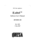
Operating Instructions
Integrated Transducers
UFA-, UVA-, UTA-Ex-d
zertifiziert nach
ISO 9001 : 2000
certified quality
Annex
Operating Instructions
Transducers UFA / UVA /UTA
integrated in
vane wheel sensors,
vortex sensors,
or thermal sensors
with Ex-d housing
Contents
A1 Scope of Delivery
A1.1
Description, Type Plates
A2 Technical Specifications
A2.1
Operating Conditions
A2.2
Housing and Connections
A2.3
Electrical Data
A2.4
Measurement Uncertainty
A3 Installation
A3.1
Pin Assignment
A3.2
Wiring Diagrams
A3.2.1 Power supply
A3.2.2 Analog output v
A3.2.3 Digital output (relay output)
A3.2.4 HART interface
A3.2.5 optional LCD display
A4 Functional Description
A5 Settings
A6 Initial Operation
A7 Operation
A8 Shut-down, Dismantling
A9 Inspection
A10 Troubleshooting
A11 Replacement Parts
U377_UxAintExd_B_e_120426
www.hoentzsch.com
1/11
Operating Instructions
Integrated Transducers
UFA-, UVA-, UTA-Ex-d
A1
Scope of Delivery
- Transducer UFA, UVA or UTA integrated in the connection housing of flow sensor FA, VA or TA
- Operating Instructions Flow Sensor FA, VA or TA;
Data Sheet flow sensor FA, VA or TA with integrated transducer UFA, UVA or UTA
- CD-ROM with PC configuration software UCOM (optional)
- HART modem for PC connection to COM or USB port (optional)
Please check that everything listed in the Delivery Note / Technical Data Sheet is included in the delivery.
A1.1
Description, Type Plates
One of the following type plates (or similar) can be found on the connection housing:
FA, FAR
VA
TA
: vane wheel flow sensor
: vortex flow sensor VA40
: thermal flow sensor
UFA
UVA
UTA
: transducer for vane wheel sensors FA
: transducer for vortex sensors VA
: transducer for thermal sensors TA
PS
: max. permissible pressure (absolute)
S.No.
Di
: serial number
: inside diameter Di of the measuring tube
Tamb
: ambient air temperature range connection housing -20...+50 °C
Tmedium
: temperature range of medium
Pin assignment of connecting terminals:
KL1
DC Power
L+
L-
KL2
Output 4..20mA +
-
KL3 Output relay (2 terminals)
2/11
: +24 VDC
:
0 VDC
= supply voltage +24 VDC
= supply voltage
0 VDC
: +4..20mA
: - 4..20mA
= Output Flow
= Output Flow
:
= normally open contact potential-free
www.hoentzsch.com
U377_UxAintExd_B_e_120426
Operating Instructions
Integrated Transducers
UFA-, UVA-, UTA-Ex-d
A2
A2.1
Technical Specifications
Operating Conditions
Ambient temperature
of connection housing
when in use
: -20 ... +50 °C
Type of protection
: IP68
A2.2
Housing and Connections
Type of protection
Setup
: housing IP68
: dual chamber system Ex-d = electronics, Ex-e = connection chamber
Material
External dimensions
Connections
: aluminium
: D/L/H = 110/205/182 mm
: 2 cable bushings in Ex-e protection in the connection chamber, in which
6 terminals in Ex-e protection for wires with cross-section 0.14...1.5
mm² can be found
A2.3
Electrical Data
Supply voltage,
mains supply
supply current
24 V DC (20 ... 27 V DC), power < 5 W
<150 mA
The mains supply is electrically isolated from the outputs.
The "-" connection of the analog output can be found on the housing and so on the equipotential bonding
PA, i.e. on EMC grounds the signal interpretation should have potential-free inputs.
The relay output is potential-free.
Analog output
: 4 ... 20 mA = 0 ... x m/s (or m³/h)
4 ... 20 mA = -x ... 0 ... +x m/s (or m³/h) with FAR
function configurable;
terminal value x configurable / resistance max. 500 Ohm,
with HART interface 250 ... 500 Ohm
Digital output
: (relay contact, normally open contact), max. 200 mA / 30 V DC,
configurable as limit value v, quantity pulse or
±direction of flow (see A4 Functional Description A4)
HART interface
: for communication with PC programme UCOM
(see Functional Description A4)
Accessible by unscrewing the glass housing (optional):
Connection
for optional LCD display
U377_UxAintExd_B_e_120426
: flat ribbon cable with 10-pin cable socket
DO NOT PLUG IN OR OUT WHEN LIVE!
www.hoentzsch.com
3/11
Operating Instructions
Integrated Transducers
UFA-, UVA-, UTA-Ex-d
A2.4
Measurement Uncertainty
Acquisition of measurement frequency (at 1000 Hz) : <0.1%
Analog output (terminal value)
: <0.15%
Linearity error
: <0.1%
Temperature coefficient
: <20 ppm/K (at 25 °K temperature difference
equivalent to <0.05%)
A3
Installation
Authoritative here are the relevant national regulations for installing electrical equipment, the General
Engineering Regulations and these Operating Instructions.
A3.1
Pin Assignment
Connecting terminals transducer
Connecting terminals are accessible after removing the housing cover of the connection chamber (housing cover on the cable bushing side).
A3.2
Wiring Diagrams
Electrical connection must be carried out according to the appropriate wiring diagram. Faulty connection
can cause damage to the electronics.
Do not install or wire up the transducer under mains voltage. Non-compliance can cause damage to
the electronics.
4/11
www.hoentzsch.com
U377_UxAintExd_B_e_120426
Operating Instructions
Integrated Transducers
UFA-, UVA-, UTA-Ex-d
A3.2.1
Power supply
Before connecting please check that the power supply is within the specification. All relevant information
can be found on the type plate.
PA terminal on
the exterior of
the housing
24 V DC
(20 … 27 V DC)
A3.2.2
PA local equipotential bonding
Analog output v
Shielding terminals in the interior of the
Housing (connection chamber)
Shielding terminal in
the interior of the housing
(connection chamber)
4-20 mA
Resistance max. 500 Ohm or with
4-20 mA
HART interface 250 ... 500 Ohm
Resistance max. 500 Ohm or with
HART interface 250 ... 500 Ohm
The analog output is configurable with the PC software UCOM via the HART interface. The factoryprogrammed values can be found in the accompanying documents.
U377_UxAintExd_B_e_120426
www.hoentzsch.com
5/11
Operating Instructions
Integrated Transducers
UFA-, UVA-, UTA-Ex-d
A3.2.3
Digital output (relay contact)
The digital output is a potential-free relay contact (normally open contact).
The function of the digital output and the corresponding setting parameter are configurable using the
FCOM software via the HART interface. The factory-programmed settings can be found in the parameter
printout included with delivery.
The digital output (relay contact) can be configured for 1 of 3 functions:
1. as limit value for the flow velocity or flow rate:
flow velocity < or = limit value: relay contact open
flow velocity
> limit value: relay contact closed
2. as quantity pulse for quantity measurement:
max. pulse repetition frequency 1 Hz per unit of volume,
configurable, e.g. 1 pulse per 1, 10 or 100 (norm)-m³ or (norm)-litre
pulse duration 0.5 s (with FAR sensors: configurable for '+' or '-' amounts)
3. as ±direction of flow ** (FAR sensors only):
+direction: relay contact open
- direction: relay contact closed
** analog output is then absolute value of flow only, without direction
A3.2.4
HART interface
To connect the HART interface an optional HART modem is connected to the closed circuit of the analog
output 4..20 mA (connect to +4..20mA terminal and -4..20mA terminal). The polarity of the HART modem
connection is irrelevant. The resistance of the 4...20 mA circuit must not fall below 250 Ohm and not exceed 500 Ohm.
Connection to PC is via a COM port or a USB connection, depending on the type of HART modem.
Total resistance
Total burden
250 … 500 Ohm
HART modem
HART
modem
PC connection
6/11
PC connection
www.hoentzsch.com
U377_UxAintExd_B_e_120426
Operating Instructions
Integrated Transducers
UFA-, UVA-, UTA-Ex-d
A3.2.5
LCD display behind inspection glass in housing cover (optional)
Fig. 1: optional LCD display behind glass
(5)
(6)
(4)
(1)
(2)
(3)
Fig. 2: LCD display with cover open
Gehäusedeckel
After unscrewing the housing cover with inspection glass and the display cover plate, the complete display
module (1) can be rotated in steps of 90° after loosening the 4 retaining screws (2).
The flat ribbon cable with 10-pin connector should not be plugged in or unplugged when live!
Risk of damage to equipment!
Visible are the readout potentiometer (3) for the display contrast, the reset button (4) for the counter, the
jumpers St1 m/s-m³/h (5) and St2 A-B (6) (see A4 Functional Description).
U377_UxAintExd_B_e_120426
www.hoentzsch.com
7/11
Operating Instructions
Integrated Transducers
UFA-, UVA-, UTA-Ex-d
A4
Functional Description
UFA transducers for vane wheel probes FA and FAR (directional sensing) and vane wheel measuring
tubes FA Di and FAR Di (directional sensing) for measuring flow velocity or flow rate of air/gases and
water/liquids.
UVA transducers for vortex sensors VA for measuring flow velocity or flow rate of air/gases.
UTA transducers for thermal sensors TA for measuring standard flow velocity or standard flow rate of
air/gases.
The signal frequency or voltage generated from the flow sensor is converted to a linear analog output
signal 4-20 mA. The analog terminal value is configurable.
When logging directional sensing data, the zero point can be selected in the middle of the analog range, or
display of flow direction takes place with the aid of the digital output:
for FA and FAR*: 4 ... 20 mA
=
0 ... x m/s (or m³/h)
for FAR:
4 ... 12 ... 20 mA
=
-x ... 0...+x m/s (or m³/h)
for VA:
4 ... 20 mA
=
0 ... x m/s (or m³/h)
* for FAR sensors configuration of the digital output (see below): ±direction of flow
With transducers UFA and UVA the actual velocity / actual flow rate can be converted to standard velocity
/ standard flow rate by entering the parameters 'temperature' and 'pressure'. Working temperature and
pressure should be constant.
A digital output (relay contact) can be configured for 1 of 3 functions:
1. as limit value for the flow velocity or flow rate:
flow velocity < or = limit value: relay contact open
flow velocity
> limit value: relay contact closed
2. as quantity pulse for quantity measurement:
max. pulse repetition frequency 1 Hz per unit of volume,
configurable, e.g. 1 pulse per 1, 10 or 100 (norm)-m³ or (norm)-litre
pulse duration 0.5 s (with FAR sensors: configurable for '+' or '-' amounts)
3. as ±direction of flow ** (FAR sensors only):
+direction: relay contact open
- direction: relay contact closed
** analog output is then absolute value of flow only, without direction
Self diagnosis according to NAMUR NE43:
No error
or
: analog output
analog output
= 4 mA
> 4 mA
Error
: analog output
< 3.6 mA
(flow velocity = 0)
(flow velocity > 0)
For monitoring of power supply, data logging, sensor interface, parameter settings (see under A10:
Troubleshooting)
HART interface
for changing calibration data and setting parameters.
Connect HART modem (optional) to transducer UFA/UVA/UTA on the closed circuit of the analog output
(connect to both terminals of the analog output 4..20 mA, polarity of the connecting terminals of the HART
modem is irrelevant, resistance min. 250 Ohm, max. 500 Ohm to be strictly observed). Connect Sub-D to
the PC RS232 socket or USB plug to the USB PC connection.
Changes to the settings can now take place after starting the PC programme UCOM (optional)
(see under A5: Settings).
8/11
www.hoentzsch.com
U377_UxAintExd_B_e_120426
Operating Instructions
Integrated Transducers
UFA-, UVA-, UTA-Ex-d
Optional LCD display behind inspection glass in the housing cover:
2 x 16 digit, character height 5.5 mm
Display line 1
Display line 2
: instantaneous value velocity or flow rate
: 'counter' or 'error code'
Configuration (see Fig. 2, under A3.2.5) via 2 jumper wrap connections St1 m/s-m³/h and St2 A-B
Display line 1:
m/s-m³/h = m/s
m/s-m³/h = m³/h
m/s-m³/h = m³/h
and A-B = any:
and A-B = A:
and A-B = B:
velocity in (N)m/s *
flow rate in (N)m³/h
flow rate in (N)lt/h **
* standard values (N) UFA and UVA only, when parameter 'switching v/NV' =1 (see under A5)
** only when Di < 75.0 mm, otherwise display in (N)m³/h
Display line 2:
Quantity counter in m³ with 0 ... 3 decimal places
(see under A5: parameter 'switching pulse m³(cbm) / l (litre)' and
parameter 'm³ (cbm) / l (litre) per pulse' and
parameter 'decimal places quantity display')
with error
: error 01 = parameter error
error 02 = sensor error
(see A10: Troubleshooting)
Reset button on the LCD display module behind the glass of the housing cover: see Fig. 2,
A3.2.5:
Reset the counter by pressing the reset button for more than 3 seconds. This can also be carried out via
the HART interface.
A5
Settings
The following setting parameters can be read using the PC software UCOM and are also alterable.
The customer-specific settings are shown on the parameter print-out, which is included in the
documents.
Please find operation instructions PC software UCOM in document U385.
A6
Initial Operation
(Pay attention to A3.2.1 Power supply and A3.2.2 Analog output)
On connecting the supply voltage:
no flow at sensor: the analog output sends a value of 4 mA (or 12 mA depending on configuration with
FAR sensors, see under A4 Functional Description)
flow at sensor: the analog output sends an analog value deviating from the zero flow conditions (see
above).
U377_UxAintExd_B_e_120426
www.hoentzsch.com
9/11
Operating Instructions
Integrated Transducers
UFA-, UVA-, UTA-Ex-d
A7
Operation
(Pay attention to A2.1 Operating Conditions)
(Pay attention to A2.3 Electrical Data)
A8
Shut-down, Dismantling
Before disconnecting the cable please ensure that the supply voltage is switched off.
A9
Inspection
see under A4 Functional Description, self diagnosis.
The screw threads of the housing cover have been treated with graphite as protection against corrosion.
10/11
www.hoentzsch.com
U377_UxAintExd_B_e_120426
Operating Instructions
Integrated Transducers
UFA-, UVA-, UTA-Ex-d
A10
Troubleshooting
Fault
Cause
Troubleshooting
Analog output =
0 mA
No power supply
Check connecting cable, measure voltage at
connecting terminals
Return to factory
Check parameter with UCOM software, save
new checksum (or return to factory)
Return to factory
Clean sensor according to instructions
Analog output =
error (<3.6 mA)
Analog output =
4 mA,
no measured value
Measured value too
low
Transducer electronics faulty
Parameter error
Transducer electronics faulty
Sensor contaminated
Coefficient set at 0.000
Sensor contaminated
Coefficient setting too low
Input/output section too
short
Rotational flow
VA sensors:
Reduced acoustic coupling in
the sensor elements as a
result of intense vibration or
a powerful impact
Set coefficient to relevant nominal diameter and
sensor type
Clean sensor according to instructions
Set coefficient to relevant nominal diameter and
sensor type
Change sensor position; improve flow
conditions with a flow rectifier
Reposition sensor in flow direction; install flow
rectifier
Return sensor to factory for performance check
Resistance at current output Reduce resistance value
is greater than specified in
the Technical Data Sheet.
This results in correct output
values in the lower range and
no longer increasing output
values at the top end of the
measuring range
Measured value too
high
Incorrect scaling of analog
output
Check setting and amend if necessary
Coefficient set too high
Set coefficient to relevant nominal diameter and
sensor type
See reference to electromagnetic compatibility
(EMC)
EMC problem
A11
-
Replacement Parts
Cable bush in Ex-e protection
Inspection glass-housing cover
Housing cover (without inspection glass)
Seals for housing cover
The fuse is self-restoring
U377_UxAintExd_B_e_120426
www.hoentzsch.com
11/11