1
FTEC
FTEC02-03
O2
ISTRUZIONI DI SERVIZIO
OPERATING INSTRUCTIONS
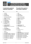
Il controllo della capacità
e l’avviamento a vuoto nei
compressori semiermetici
Capacity control and
unloaded start for semihermetic compressors
Indice
Index
1.
Introduzione
1.
Generals
2.
2.1
2.2
La testa
Principio di funzionamento
Descrizione della testa
2.
2.1
2.2
head
The
Description of the operation
Description of the
head
3.
La testa US
3.
US head
4.
Riduzione della capacità frigorifera
4.
Reduction of the cooling capacity
5.
Funzionamento della testa US
5.
Operation of the US head
6.
6.1
6.2
6.3
6.4
6.5
6.6
6.7
6.8
6.9
Vantaggi e limiti di impiego
I vantaggi
I limiti di impiego con la testa
L’assorbimento elettrico
La temperatura delle teste
La temperatura del lubrificante
La migrazione del lubrificante
Le vibrazioni del compressore
Campo di impiego
Il raffreddamento supplementare
6.
6.1
6.2
6.3
6.4
6.5
6.6
6.7
6.8
6.9
Advantages and application limits
Advantages
head
Application limits with
Input power
Head temperature
Lubricant temperature
Lubricant migration
Compressor vibrations
Application range
Additional cooling
7.
7.1
7.2
Installazione della testa
Montaggio della testa
Controllo della valvola elettromagnetica della testa
7.
7.1
7.2
head
Installation of the
Mounting the
head
Control of the solenoid valve of the
8.
8.1
8.2
Installazione della testa US
Raccomandazioni
Procedura di montaggio
8.
8.1
8.2
Installation of the US head
Remarks
Mounting instructions
9.
9.1
9.2
9.3
Il circuito frigorifero
Dimensioni delle linee frigorifere
La configurazione delle linee frigorifere
La valvola d’espansione termostatica
9.
9.1
9.2
9.3
Piping
Piping size
Piping outline
The thermostatic expansion valve
10. Dati tecnici
10. Technical data
11.
11.1
11.2
11.3
11.4
11.5
11.6
11.7
11.8
11.9
11.
11.1
11.2
11.3
11.4
11.5
11.6
11.7
11.8
11.9
Campi di impiego
Campo di impiego con R404A/R507A - compressori serie Q,S e V
Campo di impiego con R404A/R507A - compressori serie Z
Campo di impiego con R404A/R507A - compressori serie W
Campo di impiego con R134a - compressori serie Q, S e V
Campo di impiego con R134a - compressori serie Z
Campo di impiego con R134a - compressori serie W
Campo di impiego con R22 - compressori serie Q, S e V
Campo di impiego con R22 - compressori serie Z
Campo di impiego con R22 - compressori serie W
Application range
Application range with R404A/R507A - Q, S and V series compressors
Application range with R404A/R507A - Z series compressors
Application range with R404A/R507A - W series compressors
Application range with R134a - Q, S and V series compressors
Application range with R134a - Z series compressors
Application range with R134a - W series compressors
Application range with R22 - Q, S and V series compressors
Application range with R22 - Z series compressors
Application range with R22 - W series compressors
12. Schemi elettrici
12. Electrical wirings
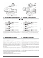
13. Modelli delle teste US e parti di ricambio
13. US head models and spare parts
Istruzioni di servizio
1
head
Operating instructions
•
FRASCOLD SpA si riser va il
diritto di modificare i dati e le
caratteristiche contenute nel
presente catalogo, senza obbligo
di preavviso.
FTEC02-03
FRASCOLD SpA reserves the
r i g h t t o c h a n g e a t a n y t i m e,
specifications or design without
notice and without incurring
obligations.
Ref: FTEC02-03
Edizione: Dicembre 2008
sostituisce: FTEC02-02
Febbrario 2008
sostituisce: FTEC05-00
Giugno 2003
Realizzazione: FRASCOLD SpA
Istruzioni di servizio
2
Operating instructions
FTEC02-03
1. Introduzione
1. Generals
Nell’ambito della progettazione di un impianto di raffreddamento, il
compressore selezionato ha una capacità sufficiente a smaltire il picco
del carico termico della struttura e alternare periodi di arresto e
funzionamento con una frequenza compatibile con il massimo numero di
cicli/ora del compressore stesso (vedi manuale di installazione e avviamento
FTEC01, “1.11 Limiti di impiego).
Ma, mentre la capacità frigorifera del compressore è costante (se
rimangono costanti le temperature di funzionamento), il carico termico
varia continuamente al variare delle condizioni operative; per esempio,
quando si verifica una diminuzione dell’affollamento nell’ambiente
condizionato o il massiccio prelievo di merce da una cella frigorifera.
In condizioni di carico ridotto, il compressore è in grado di portare la
struttura alla temperatura di progetto in un tempo più breve; se non si
adottano opportuni accorgimenti per compensare tale situazione, diversi
inconvenienti concorrono a compromettere l’efficienza dell’intero impianto
di raffreddamento.
Prima di tutto è necessario verificare se l’aumentato numero di avviamenti/ora
del compressore (che deriva da un più breve periodo di raffreddamento)
è compatibile con il massimo che il compressore può sopportare (vedi il
manuale di installazione e avviamento FTEC01, paragrafo 1.10 “I cicli di
funzionamento” e 1.11 “Limiti di impiego”); si ricorda che gli avviamenti
troppo frequenti accorciano sensibilmente la vita operativa del compressore.
Un’altro aspetto negativo, è la tendenza all’abbassamento della temperatura
di evaporazione con conseguente diminuzione del punto di rugiada
dell’evaporatore ed eccessiva deumidificazione dell’aria trattata creando
così condizioni di non comfort in un impianto di condizionamento oppure
provocando un sensibile calo di peso del prodotto conservato in una cella
frigorifera.
In entrambi i casi, il calo di temperatura a valori negativi sarebbe causa
di formazione di ghiaccio sull’evaporatore con conseguenze facilmente
immaginabili.
Molte sono le soluzioni per adeguare la capacità frigorifera al carico termico;
una, per esempio, è quello di installare più compressori di piccola potenza
al posto di uno solo di grande potenza.
Oltre a un maggiore costo iniziale e a un sistema di controllo più complicato,
tale soluzione non annulla l’inconveniente del frequente ciclaggio dei
compressori per fare fronte alla variazione del carico termico.
Il sistema più semplice per compensare lo squilibrio tra carico termico
variabile e capacità frigorifera costante è fare in modo di rendere variabile
anche quest’ultima, seguendo le fluttuazioni del carico termico.
Annullando l’effetto di “pompaggio” di una parte dei pistoni del compressore,
se ne modifica la sua portata ponderale totale e di conseguenza la sua
capacità frigorifera.
Within the scope of the designing of a cooling system, the selected
compressor must have a capacity adequate to carry off the maximum
calculated heat load and, in the mean time, to operate run and standstill
periods.
The sequence of compressor start and stop must meet the maximum
stop/start cycle (see installation and start-up manual FTEC01, “1.11
Application limits” ).
But, while the cooling capacity of the compressor is steady (if steady are
the operational temperatures), the heat load rise and fall on changing
of operational conditions; e.g. when into an air-conditioned area the
crowding decreases or when in the cold-room a large good withdrawal
takes place.
With reduced heat load the compressor is able to cool the plant down to
the design temperature in a shorter period.
Without proper devices to compensate such circumstance, several troubles
occur to endanger the efficiency of the whole cooling system.
It is essential to verify if the increased sequence of compressor stop/start
(due to the shorter cool-down period) is consistent with the maximum
stop/start cycle (see installation and start-up manual FTEC01, “1.11
Application limits” ); please, note that a too frequent start/stop reduces
considerably the compressor lifetime.
Another negative point is the trend of the evaporating temperature to drop
causing the decrease of the dew point of the evaporator and the excessive
dehumidification of the cooled air.
That results in the uncomfortable condition for a air-conditioning system
or a excessive loss in weight for the product stored in the cold room.
In both situations, the temperature lowered down to negative value can
freeze the evaporator surface with the believable conseguences.
Several options are available to adequate compressor capacity to the
heat load; e.g. one could be the installation of more compressors with
small capacity instead of one only with large capacity.
Such solution is distinguished with an initial higher cost and with a complex
control system but it doesn’t undo the negative effetc of the frequent start/
stop sequence to meet the heat load variations.
The simplest and most commonly used solution to compensate the
disproportion between unsteady heat load and fix cooling capacity is to
bring out compressor capacity changement by means removing the
“pumping” effetc of part of the compressor pistons.
In such a way the flow mass is reduced and, consequently, the cooling
capacity also.
2. La testa
2. The
Per variare la capacità frigorifera dei suoi compressori, FRASCOLD ha
realizzato le teste
(Capacity Control) adatte per equipaggiare tutti
i compressori:
- con 4 cilindri (2 teste) serie Q, S e V
- con 6 cilindri (3 teste) serie Z
- con 8 cilindri (4 teste) serie W
A richiesta, il compressore viene fornito già completo di testa
;
applicando le procedure illustrate a pagina 7, paragrafo 5.1 “Montaggio
della testa
, l’operatore è in grado di montare tale dispositivo sul
compressore già installato.
To modify the cooling capacity of the compressor, FRASCOLD has realized
the
heads (Capacity Control) suitable to fit all the models:
- with 4 cylinders (2 heads) series Q, S and V
- with 6 cylinders (3 heads) series Z
- with 8 cylinders (4 heads) series W
On request, compressor can be supplied with
head installed in factory;
performing the procedures illustrated at page 7, section 5.1 “Installation
of
head, the operator is able to mount it on a compressor already
installed in to the cooling system.
Istruzioni di servizio
3
head
Operating instructions
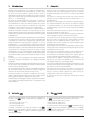
2.1 Principio di funzionamento
La valvola elettromagnetica, installata su una testa
appositamente
studiata e realizzata per tale scopo, sfrutta la pressione di compressione del
compressore per intercettare il flusso di refrigerante aspirato dalla coppia
di pistoni dotati di tale dispositivo.
è essenzialmente composta da:
La testa
z valvola elettromagnetica
{ camera di bassa pressione (pressione di aspirazione
| camera di alta pressione (pressione di compressione)
} otturatore
~ molla di richiamo
testa
2.1 Description of the operation
The solenoid valve, placed on a
head,specially realized for the
specific purpose, utilizes the discharge pressure of the compressor
to cut-off the suction refrigerant flow of the couple of cylinders fitted
with such head.
head, essentially, includes:
The
z solenoid valve
{ low pressure chamber (suction pressure)
| high pressure chamber (discharge pressure)
} stopper
~ return spring
head
z
z
{
{
~
}
|
~
|
funzionamento a pieno carico
full load operation
fig. 1
Durante il funzionamento a pieno regime del compressore, la bobina della
valvola elettromagnetica non è alimentata e il pistone, mantenuto sollevato
dalla molla antagonista, lascia libero il passaggio di aspirazione della piastra
valvole (vedi figura 1) consentendo il regolare flusso di refrigerante tra
l’aspirazione e l’interno del cilindro.
In caso di riduzione del carico termico, la temperatura e la pressione
di evaporazione diminuiscono, il dispositivo di regolazione dell’impianto
frigorifero provvede ad alimentare elettricamente la bobina della valvola
elettromagnetica.
La valvola elettromagnetica si apre mettendo in comunicazione la camera
di compressione della testata con la sede dell’otturatore (vedi figura 2).
L’alta pressione del refrigerante agisce sulla testa dell’otturatore del
dispositivo e, vincendo l’azione combinata della molla antagonista e della
pressione di aspirazione, lo spinge verso il basso chiudendo il passaggio
di aspirazione della piastra valvole.
Così facendo, viene annullato l’effetto pompante della corrispondente
coppia di pistoni.
funzionamento a carico ridotto
capacity control operation
fig. 2
When the compressor runs with full load, the power to the coil of the
solenoid valve is off, the piston is lift by the spring and the suction port
of the valve plate is open (see fig.1) allowing the refrigerant to flow
through allowing the regular flow between suction and inside of the
cylinder.
When the heat load is reduced, the suction temperature and pressure
drop down, the regulation control of the cooling system cuts off the
power to the coil of the solenoid valve.
The solenoid valve open, in such a way the discharge pressure is
addressed to the upper side of the stopper (see fig.2).
The high pressure operates on the head of the stopper and, beeing
higher than the joined effect of suction pressure and return spring
force, it is pressed downward closing the suction port of valve plate.
The results is the removing of the “pumping” effetc of the relative couple
of cylinders.
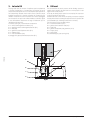
2.2 Descrizione della testa
La testa
è disponibile in tre modelli:
•
modello T00SK220150; per compressori serie Q (fig. 3)
•
modello T00SK220100; per compressori serie S (fig. 3)
•
modello T00SK220200; per compressori serie V, Z e W (fig. 4)
Ogni modello di testa
è composta da:
n°1 valvola elettromagnetica con bobina (rif. 1)
n°1 guarnizione valvola elettromagnetica/flangia (rif.2)
n°1 testata
(rif.3)
n°1 guarnizione testata/piastra valvole (rif.4)
n°1 segmento dell’otturatore (rif.5)
n°1 otturatore (rif.6)
n°1 molla dell’otturatore (rif.7)
head
2.2 Description of the
Three models of
head are available:
•
model T00SK220150; for compressors series Q (fig. 3)
•
model T00SK220100; for compressors series S (fig. 3)
•
model T00SK220200; for compressors series V, Z and W (fig. 4)
Each model of
head is complete with:
n°1 solenoid valve with coil (ref. 1)
n°1 gasket solenoid valve/flange (ref.2)
head (ref.3)
n°1
n°1 gasket head/valve plate (ref.4)
n°1 ring of the stopper (ref.5)
n°1 stopper (ref.6)
n°1 return spring of the stopper (ref.7)
Istruzioni di servizio
4
Operating instructions
FTEC02-03
}
3. La testa US
3. US head
L’impiego della testa US consente di equalizzare quasi completamente
e pressioni di aspirazione e di compressione (la pressione del lato di
compressione sarà superiore di circa 0.5 bar rispetto a quella presente nel
lato di aspirazione), riducendo in tale modo lo sforzo e quindi la corrente
assorbita necessaria per il completo avviamento del compressore. Per
effettuare l’avviamento in vuoto il compressore deve essere equipaggiato
con una testa US che può venire montata in fabbrica a richiesta, oppure
a cura dell’installatore direttamente sul luogo di installazione (vedi 4.
“Installazione della testa US”).
La testa US (vedi fig.A1) è essenzialmente composta da:
• n°1 valvola elettromagnetica con bobina (rif. 1)
• n°1 guarnizione valvola elettromagnetica/testa US (rif.2)
• n°1 testa (rif.3)
• n°1 guarnizione testa US/piastra valvole (rif.4)
• n°1 otturatore (rif.5)
• n°1 molla dell’otturatore (rif.6)
• passaggio di by-pass aspirazione/compressione (rif.7)
The US head allows the suction pressure and the discharge pressure to
equalize nearly completely; the final result is a common pressure 0.5 bar
higher than the suction pressure.
In this way, the starting torque required to run completely the compressor
is reduced as well the input current.
Unloaded start mode can be carried out requiring a compressor equipped
in factory with US head or mounting this equipment on the compressor after
its field installation (see “ Mounting instructions for US head”)
The US head (see fig.A1) essentially includes:
• n°1 solenoid valve with coil (ref.1)
• n°1 gasket solenoid valve/US head (ref.2)
• n°1 head (rif.3)
• n°1 gasket US head/valve plate guarnizione (ref.4)
• n°1 stopper (ref.5)
• n°1 spring (ref.6)
• suction/discharge by-pass opening (ref.7)
FTEC02-03
1
2
5
7
6
3
4
fig. A1
Istruzioni di servizio
5
Operating instructions
1
1
2
2
3
3
4
4
5
5
6
6
7
7
modello T00SK220200
T00SK220200 model
fig. 4
4. Riduzione della capacità frigorifera
4. Reduction of cooling capacity
Ogni compressore serie Q, S, V, Z e W può essere dotato di testa
;
pertanto i gradini di riduzione sono:
•
compressori con 4 cilindri (serie Q, S e V)
- con 1 testa
- capacità volumetrica ridotta al 50% del valore dichiarato
•
compressori con 6 cilindri (serie Z)
- con 1 testa
- capacità volumetrica ridotta al 66% del valore dichiarato
- con 2 teste
- capacità volumetrica ridotta al 33% del valore dichiarato
•
compressori con 8 cilindri (serie W)
- con 1 testa
- capacità volumetrica ridotta al 75% del valore dichiarato
- con 2 teste
- capacità volumetrica ridotta al 50% del valore dichiarato
È importante notare che a una riduzione della capacità volumetrica, non
corrisponde una pari riduzione percentuale sia della capacità frigorifera che
della potenza assorbita.
La tabella Dati tecnici illustra la effettiva variazione di capacità frigorifera e
di potenza assorbita ai diversi gradini di parzializzazione.
head can be installed on each Q, S, V, Z and W series compressor;
the attainable steps of reduction are:
•
compressors with 4 cylinders (series Q, S and V)
- with 1
head
- displacement reduced down to 50% of the nominal value
•
compressors with 6 cylinders (series Z)
head
- with 1
- displacement reduced down to 66% of the nominal value
- with 2
heads
- displacement reduced down to 33% of the nominal value
•
compressors with 8 cylinders (series W)
- with 1
head
- displacement reduced down to 75% of the nominal value
- with 2
heads
- displacement reduced down to 50% of the nominal value
It is important to notice that with above mentioned steps of reduction don’t
correspond equal reductions of both cooling capacity and input power.
The real variations of cooling capacity and input power corresponding
to the reduction of nominal displacement are listed in Technical data”.
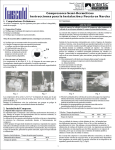
5. Funzionamento della testa US
5. Operation of the US head
Il corretto impiego della testa US consente l’avviamento del compressore
e il successivo raggiungimento della velocità di regime con le pressioni in
aspirazione e compressione tra loro equalizzate.
Durante la fase di arresto del compressore (la valvola elettromagnetica
normalmente chiusa non è alimentata elettricamente), l’azione comune
dell’alta pressione del refrigerante e della forza della molla agisce sulla
superficie superiore dell’otturatore mantenendolo in posizione di riposo(vedi
fig.A2); così facendo, il passaggio di by-pass è chiuso e nella testa US il
lato di compressione (alta pressione) rimane separato dal lato di aspirazione
(bassa pressione).
Al momento dell’avviamento del compressore, la valvola elettromagnetica
alimentata elettricamente si apre consentendo così all’alta pressione di
defluire dalla parte superiore dell’otturatore verso il lato di aspirazione
(bassa pressione) della testa.
L’alta pressione ancora presente nella parte inferiore dell’otturatore spinge il
medesimo verso l’alto aprendo così il passaggio di by-pass e consentendo
l’equalizzazione tra le pressioni (vedi fig.A3).
In pratica, dopo l’equalizzazione, la pressione si stabilizza a un valore di 0.5
bar superiore alla pressione di aspirazione.
The proper use of US head allows the compressor to start and achieve
the following working speed with suction pressure and discharge pressure
equalized.
During the compressor standstill (normally closed solenoid valve is not
powered), the mutual influence of the refrigerant high pressure and the
spring has effect on the upper part of the stopper keeping it in low position
(see fig.A2). With the stopper in low position, in the US head the opening
is closed keeping separate discharge side (high pressure) and suction
side (low position).
When compressor starting is required, the solenoid valve is powered then
it open and the high pressure can flow from the upper part of the stopper
to the suction side (low pressure) of the US head.
The high pressure still in action on the lower part of the stopper pushes
it upward, the by-pass is now open and the pressure equalization occurs
(see fig.A3). Pratically, the final equalized pressure is 0.5 bar higher than
the suction pressure.
Istruzioni di servizio
6
Operating instructions
FTEC02-03
modelli T00SK220100 / T00SK220150
T00SK220100 / T00SK220150 models
fig. 3
N.B. For a complete compressor starting with equalized pressures
it is essential to power the solenoid valve 5-10 seconds before
to power the compressor contactors.
N.B. Per garantire che all’avviamento del compressore
l’equalizzazione tra le pressioni sia stata completata, è
necessario alimentare la valvola elettromagnetica 5-10 secondi
prima di alimentare i teleruttori del compressore.
Keep on powered the solenoid valve at least 3-5 seconds after the
compressor starting to permit the full operational speed to be settled.
When the above mentioned delay is expired, cut off the power to the
solenoid valve to put back in operation the compressor (see fig.2).
FTEC02-03
La valvola elettromagnetica deve rimanere alimentata per altri 3-5 secondi
dopo l’avvio del compressore per consentire al medesimo il raggiungimento
della velocità di regime. Al termine di tale ritardo, viene interrotta
l’alimentazione elettrica alla valvola elettromagnetica che chiudendosi
ripristina le condizioni di normale funzionamento del compressore (vedi
fig.A2).
Funzionamento normale
Regular operation
fig. A2
Avviamento a vuoto
Unloaded start
fig. A3
6. Vantaggi e limiti di impiego
6. Advantages and application limits
6.1
•
•
•
•
6.1
•
•
•
•
I vantaggi
riduzione della fluttuazione della temperatura di evaporazione
capacità frigorifera costante adeguata all’effettivo carico termico
riduzione del numero di cicli arresto/avviamento del compressore
riduzione della potenza assorbita al diminuire della capacità frigorifera
6.2 Application limits with
head
The capacity control operation influences other operational parameters of
the compressor as:
•
electrical input
•
head temperature
•
lubricant temperature
•
lubricant migration
•
compressor vibrations
•
application range
•
additional cooling
6.2 I limiti di impiego con la testa
Il funzionamento a carico ridotto del compressore influenza alcuni parametri
di funzionamento del compressore quali:
•
assorbimento elettrico
•
temperatura delle testate
•
temperatura del lubrificante
•
migrazione del lubrificante
•
vibrazioni del compressore
•
campo di impiego
•
raffreddamento supplementare
Istruzioni di servizio
Advantages
reduction of evaporating temperature fluctuation
cooling capacity constantly adjusted to the effective heat load
reduction of stop/start cycle of the compressor
input power reduced when cooling capacity decreases
7
Operating instructions
It is suggestable to carefully check of the operational parameters in order
to verify they aren’t in conflict both with normal operational conditions
of cooling system design and with the application limits of the
compressor.
6.3 L’assorbimento elettrico
Durante il funzionamento con capacità frigorifera ridotta, l’assorbimento del
compressore non diminuisce esattamente della stessa percentuale.
Per esempio, IN caso di funzionamento con capacità ridotta al 50%,
l’assorbimento elettrico si riduce al 62÷63% del valore totale.
Le percentuali di riduzione dell’assorbimento elettrico ai vari gradini di
parzializzazione sono illustrati più oltre in questo documento.
6.3 Input power
When the compressor runs with reduced capacity, the input power doesn’t
decrease with the same ratio.
For example, when the compressor runs with the 50% of the total capacity,
the input power is reduced down to 62÷63% of the total value.
The ratio of reduction related to the steps of capacity reduction are shown
later in this document.
6.4 La temperatura delle teste
Con la testa
operante, la temperatura del refrigerante gassoso subisce
sensibili variazioni rispetto a quella che si verifica durante il funzionamento
a pieno regime.
La temperatura del gas aspirato è di 5÷6 K superiore al quella normale, ne
consegue una temperatura di scarico superiore di 10÷15 K.
La temperatura della testa
tende a stabilizzarsi a un valore inferiore
di circa 20 K inferiore a quella delle testate normali.
6.4 Head temperature
head is operating, the temperature of refrigerant gas has
When the
an appreciable modification compared to the one measured during the
full operation mode.
The suction gas temperature is 5÷6 K higher than normal temperature, the
result is an higher discharge temperature of 10÷15 K.
The temperature of
head becomes stable to a value of 20 K lower
than the temperature mesured on standard head.
6.5 La temperatura del lubrificante
L’aumento della temperatura di compressione causa, nel tempo, un aumento
della temperatura dell’intero corpo del compressore, compreso il lubrificante
che può raggiungere valori di 70°C quando il compressore lavora ai limiti
del suo campo di impiego privo di raffreddamento supplementare.
A causa della maggiore temperatura, la viscosità delll’olio diminuisce
sensibilmente e quindi anche il suo potere lubrificante.
Per questo motivo si consiglia di equipaggiare il compressore con un
motoventilatore per il raffreddamento delle testate; il suo impiego abbassa
la temperatura di circa 15K.
6.5 Lubricant temperature
The encreased discharge temperature leads to an higher temperature
of the whole compressor body, including the lubricant that can rise upto
70°C when the compressor is operating on the limit of application range
without additional cooling.
Due to the increased temperature, the viscosity of the lubricant considerably
lowers and, therefore, its lubricating capacity.
Because of this, it is suggestable to complete the compressor with a
motorfan for the additional head cooling; in so way the head temperature
drops down of 15K approximately.
6.6 La migrazione del lubrificante
Durante l’uso prolungato del compressore a carico ridotto, si può verificare
una migrazione di lubrificante dal lato di mandata a quello di aspirazione
del compressore.
Tale fenomeno è causato dalla depressione che si verifica in fase di
aspirazione nei pistoni della testa
.
In queste condizioni, si consiglia di equipaggiare la linea di compressione
con un separatore d’olio.
A causa della diminuita velocità del refrigerante, è necessario dimensionare
le tubazioni della linea di aspirazione in modo da garantire una velocità
del refrigerante non inferiore a 4 m/s per i tratti orizzontali e non inferiore
a 7 m/s per i tratti verticali con flusso ascendente (vedi pag.8, “6. Il circuito
frigorifero”.
Per salvaguardare il compressore dalla migrazione di lubrificante, la valvola
elettromagnetica della testa
non deve essere alimentata:
•
quando il compressore è fermo per raggiunta temperatura
di regime
•
durante il funzionamento in pump-down del compressore
•
durante l’avviamento in vuoto di un compressore dotato di motore
PWS o Δ-
6.6 Lubricant migration
When the compressor runs for extended period with reduced capacity,
a lubricant migration, from discharge side in the direction of suction
side, occurs.
This event is because the the lowering pressure during nthe suction
mode into the piston with
head.
Due to that, it is suggestable to install an oil separator on the discharge
line of the cooling system.
Because the reduced speed of the refrigerant, it is necessary to size
the suction line piping so that is assured a minimum sped of 4 m/s in
the horizontal length and 7 m/s in the upward vertical length (see page 8,
section “6. Piping”.
To protect the compressor from the migration of the lubricant, the solenoid
valve of the
head must be disconnected during the following
conditions:
•
while the compressor stops during the regular cycling
•
while the compressor is in pump-down mode
•
during the starting of the compressor equipped with PWS
or Δ- electric motor
6.7 Compressor vibrations
While the compressor runs with reduced capacity, the inside pressure
of the
head is different respect the one of the other heads; the resulting
dynamic unbalance can cause an increasing of vibrations.
6.7 Le vibrazioni del compressore
Durante il funzionamento a carico ridotto, la pressione all’interno della
testa
è diversa da quella delle altre testate; il conseguente
sbilanciamento dinamico può provocare un aumento delle vibrazioni.
6.8 Application range
Diagrams illustrated later in the manual show the application ranges of the
compressor related to the different conditions of capacity control mode
with two different conditions of the suction gas.
6.8 Campo di impiego
I diagrammi che seguono in questo manuale mostrano i campi di impiego
del compressore alle diverse condizioni di controllo di capacità e a due
diverse condizioni di temperatura del gas aspirato.
Istruzioni di servizio
8
Operating instructions
FTEC02-03
Si consiglia un attento esame dei parametri di lavoro per verificare che le
loro variazioni non siano in contrasto sia con le normali condizioni operative
previste dal progetto dell’impianto frigorifero che con i limiti di impiego del
compressore.
FTEC02-03
6.9 Il raffreddamento supplementare
Gli stessi diagrammi citati nel punto precedente indicano quando il
funzionamento a carico ridotto richiede il raffreddamento supplementare
del compressore.
Un motoventilatore installato sulle teste del compressore garantisce il
raffreddamento supplementare necessario in tali condizioni di impiego.
6.9 Additional cooling
The same diagrams cited in the previous point indicate when, while the
capacity control mode is operating, the additional cooling of the compressor
is required.
The motorfan installed in the heads of the compressor, provides the required
additional cooling.
7. Installazione della testa
7. Installation of the
7.1 Montaggio della testa
Qualsiasi compressore con 4, 6 o 8 cilindri può essere dotato della apposita
testa
.
La procedura di montaggio è la seguente:
a)
consultare la tavola 7 a pagina 9 per identificare quale testa (o
teste) del compressore deve essere sostituita con la testa
b)
interrompere l’alimentazione elettrica del compressore e adottare
tutte le necessarie precauzioni per evitare il suo avviamento
c)
chiudere i rubinetti di servizio del compressore per isolarlo dal
resto del circuito frigorifero
d)
mediante un idoneo recuperatore, estrarre tutto il refrigerante
dall’interno del compressore
e)
rimuovere le viti della testata da sostituire
f)
rimuovere la testata
g)
rimuovere la guarnizione piastra valvole/testata e sostituirla con
la guarnizione (rif.1) fornita a corredo della testa
h)
inserire il pistoncino (rif.3) nella apposita sede della testa
j)
inserire la molla antagonista (rif.2) nella parte inferiore del pistoncino
k)
posizionare la testa
sulla guarnizione precedentemente
posta sulle piastra valvole
l)
verificare che il pistoncino sia in posizione corrispondente al foro
di aspirazione della piastra valvole
m) serrare i bulloni applicando la corretta coppia di serraggio indicata
nella tabella riportata qui sotto
n)
verificare che dopo il serraggio dei bulloni della testa
, il
pistoncino scorra liberamente per 8÷8,5 mm nella sua sede fino
a chiudere il foro di aspirazione della piastra valvole
o)
montare la valvola elettromagnetica, rispettando la corretta
sequenza delle sue parti così come indicato a pagina 5, figure 3 e 4
p)
mediante una pompa per vuoto, evacuare il compressore
q)
aprire i rubinetti di servizio del compressore
r)
collegare elettricamente la bobina della valvola elettromagnetica
secondo gli schemi elettrici riportati a pagina 19 e 20
s)
ripristinare l’alimentazione elettrica del compressore
7.1 Mounting the
head
Any compressor with 4, 6 or 8 cylinders can be equipped with the
suitable
head.
The procedure for the installation is the followings:
a)
see table 7 at page 9 and identify the head (or the heads) that
has to be replaced with the
head
b)
switch-off the electrical supply to the compressor and apply all
the suitable procedures to avoid the compressor starting
c)
close the suction and discharge valves to cut the compressor off
from the cooling system
d)
by means a suitable recuperator, reclaim the whole amount of
refrigerant from the compressor
e)
remove the screws of the head to replave
f)
remove the head
g)
remove the gasket placed betweed valve plate and head and
replace it with the one (ref.1) supplied with the
head
h)
introduce the stopper (ref.3) into the seat of the
head
j)
introduce the return spring (ref.2) into the lower part of the stopper
k)
place the
head on the gasket previously placed on the
valve plate
l)
control that the stopper is located in corrispondence with the
suction port of the valve plate
m) apply to the screw the tightening torque shown at the page foot
n)
after the tightening of the screws on the
head, verify that
the stopper freely slides for 8÷8,5 mm into its seat then it closes
the suction port of the valve plate
o)
install the solenoid valve complying with the sequence of the
parts as shown at page 5, fig. 3 and 4
p)
by means a vacuum pump, evacuate properly the compressor
q)
open the suction a discharge valves of the compressor
r)
connect the coil of the solenoid valve according with the wiring
diagrams at page 19 and 20
s)
put back in the operation the electrical supply of the compressor
head
head
7.2 Control of the solenoid valve of the
a)
start the compressor
b)
power the coil of solenoid valve.
A metallic noise must be heard due to the quick touch between
stopper and valve plate.
Imput power reduction must occur.
c)
switch-off the electrical supply to the coil of the solenoid valve.
A metallic noise must be heard (not so much strong) due to the
stopper going up to its seat.
7.2 Controllo del funzionamento della valvola
elettromagnetica della testa
a)
avviare il compressore
b)
alimentare elettricamente la bobina della valvola elettromagnetica.
Si deve avvertire chiaramente un rumore metallico causato dal rapido
contatto tra l’otturatore e la piastra valvole.
La potenza assorbita deve ridursi.
c)
interrompere l’alimentazione elettrica della bobina della valvola
elettromagnetica. Si deve avvertire un rumore metallico meno
intenso causato dall’otturatore che risale nel suo alloggiamento.
La potenza assorbita compressore deve ritornare ai normali valori.
Viti della testa - coppia di serraggio - Head screw - tightening torque
serie compressore
dimensioni della vite
coppia di serraggio
Istruzioni di servizio
compressor series
screw dimension
tightening torque
Nm
Q
M8
35
S
M8
35
9
V
M10
70
Z
M10
70
W
M10
70
Operating instructions
8. Installation of the US head
8.1 Raccomandazioni
• Per evitare che il refrigerante eventualmente condensato all’interno
della linea di compressione defluisca nel compressore durante
l’avviamento in vuoto, è facoltà prevedere una valvola di ritegno a
circa 1 metro a valle del rubinetto di compressione. Nel caso di
gruppi TANDEM o racks, le valvole di ritegno sono invece obbligatorie
e devono essere in numero pari ai motori, installate sulle mandata e
sul collettore comune (in caso di compressori TANDEM).
• L’impiego di una sola testa US è sufficiente a realizzare l’avviamento
in vuoto dell’intero compressore.
• La testa US può essere montata in sostituzione di una qualsiasi delle
teste standard che equipaggiano il compressore. Si suggerisce di
rispettare le posizioni illustrate; così facendo, è possibile installare in
un secondo tempo le teste per il controllo di capacità, per le quali è
essenziale rispettare un preciso ordine di montaggio.
• Se il compressore con testa US è dotati di raffreddamento addizionale
mediante iniezione di liquido, è necessario evitare il loro funzionamento
contemporaneo inibendo l’azione della valvola di iniezione di liquido
durante l’avviamento del compressore.
8.1 Remarks
• It is recommended, although not mandatory, to install a check valve
on the discharge line to avoid the possible condensed refrigerant to
flow in to the compressor during the standstill period. The correct
position is 1 meter approximately after the discharge valve of the
compressor. In case of TANDEM units or compressor racks, the
check valves are compulsory and must be installed evenly for each
motor, installed on every discharge pipe, and one on the common
manifold (for TANDEMs).
• Just one US head is enough to have the unloaded start of the whole
compressor.
• The US head can replace any standard head located on the
compressor but it is better to respect the suggested positions. With
the suggested position it is possible equip the compressor with heads
for capacity control, which would require a specific positioning.
• If the compressor is equipped both with US head and additional cooling
by means of liquid injection, it is necessary to restrict contemporary
operation during the compressor starting.
8.2 Procedura di montaggio
Per il montaggio della testa US eseguire la seguente procedura :
a) consultare il capitolo “Dati tecnici” per identificare la testa del
compressore che deve essere sostituita con la testa US
b) interrompere l’alimentazione elettrica del compressore e adottare tutte
le necessarie precauzioni per evitare il suo avviamento
c) se non già presente, installare sulla linea di compressione la valvola
di ritegno
d) chiudere i rubinetti di servizio del compressore per isolarlo dal resto
del circuito frigorifero
e) mediante un idoneo recuperatore, estrarre tutto il refrigerante
dall’interno del compressore
f) se necessario, lasciare raffreddare tutte le teste del compressore
quindi allentare e rimuovere le viti della testa da sostituire
g) rimuovere la testa facendo attenzione a non spostare la piastra valvole
sottostante
h) rimuovere la guarnizione piastra valvole/testa e sostituirla con la
guarnizione fornita a corredo della testa US
i) serrare le viti applicando la corretta coppia di serraggio (vedi
tabella)
l) mediante una pompa per vuoto, evacuare il compressore
m) rimuovere la pompa per vuoto e aprire i rubinetti di servizio del
compressore
n) collegare elettricamente la bobina della testa US secondo gli schemi
elettrici riportati in questo manuale
o) ripristinare l’alimentazione elettrica del compressore
p) avviare in vuoto il compressore e verificare che il valore della corrente
assorbita misurata all’avviamento sia sensibilmente inferiore a quella
dichiarata nei cataloghi o manuali
8.2 Mounting instructions
For US head mounting apply, followings procedure :
a) consult the appropriate section of this manual to identify the standard
head that has to be replaced with the US type
b) disconnect the compressor from tmains to avoid the compressor
starting
c) install the check valve on the discharge line
d) close the discharge and suction valves to separate the compressor
from the cooling system
e) with a suitable refrigerant recovery unit, reclaim the refrigerant from
the compressor
f) if necessary, let the compressor heads to cool down, then slowly,
remove the screws from the head to be replaced
g) remove the head; during that operation do not move the valve plate
down below
h) remove the valve plate/head gasket and replace it with the one part
of the US head kit
i) apply to screws the correct tightening torque (see table below)
l) by means a vacuum pump evacuate the compressor
m) disconnect the vacuum pump then open suction and discharge
valves
n) connect the solenoid valve of US head (see the wiring later in this
manual)
o) connect the compressor to the mains
p) start the compressor and measure the input current, value must be
lower than must be lower respect the value shown on catalogues and
manuals
Viti della testa - coppia di serraggio - Head screw - tightening torque
serie compressore
dimensioni della vite
coppia di serraggio
Istruzioni di servizio
compressor series
screw dimension
tightening torque Nm
F
M8
35
Q
M8
35
S
M8
35
10
V
M10
70
Z
M10
70
W
M10
70
Operating instructions
FTEC02-03
8. Installazione della testa US
9. Il circuito frigorifero
9. Piping
9.1 Dimensioni delle linee frigorifere
A causa della diminuita velocità del refrigerante durante il funzionamento
a carico ridotto, è necessario dimensionare le tubazioni della linea di
aspirazione in modo da garantire una velocità del refrigerante non inferiore
a 4 m/s per i tratti orizzontali e non inferiore a 7 m/s per i tratti verticali
con flusso ascendente.
9.1 Piping size
Because the reduced speed of the refrigerant, it is necessary to size
the suction line piping so that is assured a minimum sped of 4 m/s in
the horizontal length and 7 m/s in the vertical length with upward flow.
9.2 Piping outline
During the operation with reduced capacity, the mass flow of the compressor
head is a portion of the mass flow of the full load operation.
with
In order to mantaint a suitable speed of the suction gas (and, consequently
the proper oil return) also for a compressor with reduced capacity, installed
on a level higher than the evaporator, it is necessary to realize the double
riser in the vertical length with upward flow.
FTEC02-03
9.2 La configurazione delle linee frigorifere
, il volume di gas spostato
Con il compressore dotato di testata
in condizioni di minimo carico sarà una frazione del volume spostato in
condizioni di massimo carico.
linea di aspirazione con doppio montante
suction line with double riser
fig. 5
One riser must be sized to grant the oil return when the capacity reduction
mode is in progress; the second riser operates (in parallel with the first one)
when the compressor is in full load operation.
During the reduced capacity operation, the oil slugging into the oil trap at
the foot of the main riser, addresses the refrigerant flow to the second riser
that having a smaller diameter allows higher speed of the flow.
Allo scopo di ottenere anche nelle condizioni di minimo carico una velocità
sufficientemente alta del gas aspirato (e quindi il necessario ritorno dell’olio),
quando il compressore sia installato a un livello più alto dell’evaporatore,
si ricorre all’applicazione di montanti sdoppiati nel tratto ascendente della
linea di aspirazione.
Un montante sarà dimensionato per assicurare il ritorno dell’olio in condizioni
di minimo carico, mentre l’altro lavorerà, in parallelo al primo, quando le
condizioni di carico saranno le massime.
Il ristagno del lubrificante nel sifone, che si manifesta a compressore
parzializzato, attiva il montante di diametro minore che consente più elevate
velocità di flusso.
9.3 The thermostatic expansion valve
The expansion valve selected must be able the smooth control of
the superheating of the refrigerant gas leaving the evaporator while
the compressor runs both with full capacity and reduced capacity
conditionds.
The valve adjustement must performed carefully to avoid the valve
fromhunting during operation.
The use of expansion valves expressly realized to equip cooling system
having large cooling capacity variation, is suggestable; the selection of an
oversized expansion valve must be avoided.
According to the type and cooling performances of the evaporator, it may
be required to distribute the refrigerant flow into two or more parallel circuits,
each one equipped with own solenoid valve and expansion valve.
9.3 La valvola d’espansione termostatica
La valvola d’espansione termostatica deve essere selezionata in modo tale
da garantire il surriscaldamento del gas in uscita dall’evaporatore sia durante
il funzionamento a pieno carico che a carico ridotto.
La sua taratura deve essere eseguita accuratamente al fine di evitare
pendolazioni durante il funzionamento.
Sono disponibili valvole termostatiche espressamente realizzate per impianti
con riduzione di capacità particolarmente spinta; in ogni caso, evitare di
selezionare una valvola termostatica sovraddimensionata rispetto alle
caratteristiche dell’impianto.
In funzione del tipo di evaporatore utilizzato e delle sue caratteristiche
frigorifere, è possibile che si renda necessaria una suddivisione in diversi
circuiti separati, in parallelo, ognuno dotato di propria valvola elettromagnetica
di intercettazione e valvola termostatica.
Istruzioni di servizio
11
Operating instructions
10. Dati tecnici
10. Technical data
US
US
Compressori serie Q - Q series compressors
Teste
-
head
n° x mod.
0
1 x T00SK220150
Stadi di regolazione - Capacity control stages
%
100
50
Capacità frigorifera residua - Residual refrigerating capacity
%
100
49
Potenza assorbita residua - Residual input power
%
100
57
US
US
Compressori serie S - S series compressors
Teste
-
head
n° x mod.
0
1 x T00SK220100
Stadi di regolazione - Capacity control stages
%
100
50
Capacità frigorifera residua - Residual refrigerating capacity
%
100
49
Potenza assorbita residua - Residual input power
%
100
57
US
FTEC02-03
US
Compressori serie V - V series compressors
Teste
-
head
n° x mod.
0
1 x T00SK220200
Stadi di regolazione - Capacity control stages
%
100
50
Capacità frigorifera residua - Residual refrigerating capacity
%
100
49
Potenza assorbita residua - Residual input power
%
100
57
US
US
US
Compressori serie Z - Z series compressors *
Teste
-
head
n° x mod.
0
1 x T00SK220200
2 x T00SK220200
Stadi di regolazione - Capacity control stages
%
100
66
33
Capacità frigorifera residua - Residual refrigerating capacity
%
100
66
32
Potenza assorbita residua - Residual input power
%
100
72
42
*
per una migliore visione, il compressore è rappresentato senza rubinetto di compressione - for a better compehension, compressor is reproduced without discharge valve
US
US
US
Compressori serie W - W series compressors
Teste
-
head
n° x mod.
0
1 x T00SK220200
2 x T00SK220200
Stadi di regolazione - Capacity control stages
%
100
75
50
Capacità frigorifera residua - Residual refrigerating capacity
%
100
74
48
Potenza assorbita residua - Residual input power
%
100
80
59
Istruzioni di servizio
12
Operating instructions
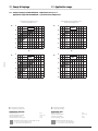
11. Campi di impiego
11. Application range
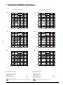
11.1 Campo di impiego con R404A/R507A - compressori serie Q, S e V
Application range with R404A/R507A - Q, S and V series compressors
Temperatura di aspirazione 20°C
Suction temperature 20°C
tc °C
Surriscaldamento in aspirazione 20K
Suction superheating 20K
tc °C
70
70
100%
100%
60
60
50
50
40
40
30
30
20
20
-40
tc °C
-30
-20
te °C
-10
0
-40
+10
tc °C
70
-30
-10
0
+10
-10
0
+10
70
50%
FTEC02-03
-20
te °C
50%
60
60
50
50
40
40
30
30
20
20
-40
-30
-20
te °C
-10
0
-40
+10
temperatura ambiente
massima temperatura della testata
massima temperatura dell’olio
massima pressione di compressione
Application data:
ambient temperature
maximum head temperature
maximum oil temperature
maximum discharge pressure
30°C
130°C ±5K
70°C
27 bar
30°C
130°C ±5K
70°C
27 bar
additional cooling with head fan motor
Q = 2700 m3/h for S series compressors
Q = 2950 m3/h for V series compressors
raffreddamento supplementare con motoventilatore in testa
Q = 2700 m3/h per compressori serie S
Q = 2950 m3/h per compressori serie V
Istruzioni di servizio
-20
te °C
te = evaporating temperature
tc = condensing temperature
te = temperatura di evaporazione
tc = temperatura di condensazione
Condizioni di impiego:
-30
13
Operating instructions
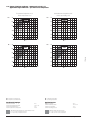
11.2 Campo di impiego con R404A/R507A - compressori serie Z
Application range with R404A/R507A - Z series compressors
Temperatura di aspirazione 20°C
Suction temperature 20°C
tc °C
Surriscaldamento in aspirazione 20K
Suction superheating 20K
tc °C
70
70
100%
100%
60
60
50
50
40
40
30
30
20
20
-40
tc °C
-30
-20
te °C
-10
0
-40
+10
tc °C
70
-30
-10
0
+10
-10
0
+10
-10
0
+10
70
66%
60
60
50
50
40
40
30
30
20
FTEC02-03
66%
20
-40
tc °C
-20
te °C
-30
-20
te °C
-10
0
-40
+10
tc °C
70
-30
-20
te °C
70
33%
33%
60
60
50
50
40
40
30
30
20
20
-40
-30
-20
te °C
-10
0
-40
+10
temperatura ambiente
massima temperatura della testata
massima temperatura dell’olio
massima pressione di compressione
Application data:
ambient temperature
maximum head temperature
maximum oil temperature
maximum discharge pressure
30°C
130°C ±5K
70°C
27 bar
30°C
130°C ±5K
70°C
27 bar
additional cooling with head fan motor; Q = 2950 m3/h
raffreddamento supplementare con motoventilatore in testa; Q = 2950 m3/h
Istruzioni di servizio
-20
te °C
te = evaporating temperature
tc = condensing temperature
te = temperatura di evaporazione
tc = temperatura di condensazione
Condizioni di impiego:
-30
14
Operating instructions
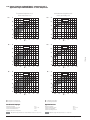
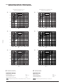
11.3 Campo di impiego con R404A/R507A - compressori serie W
Application range with R404A/R507A - W series compressors
Temperatura di aspirazione 20°C
Suction temperature 20°C
tc °C
Surriscaldamento in aspirazione 20K
Suction superheating 20K
tc °C
70
70
100%
100%
60
60
50
50
40
40
30
30
20
20
-40
tc °C
-30
-20
te °C
-10
0
-40
+10
tc °C
70
-30
FTEC02-03
-10
0
+10
-10
0
+10
-10
0
+10
70
75%
75%
60
60
50
50
40
40
30
30
20
20
-40
tc °C
-20
te °C
-30
-20
te °C
-10
0
-40
+10
tc °C
70
-30
-20
te °C
70
50%
50%
60
60
50
50
40
40
30
30
20
20
-40
-30
-20
te °C
-10
0
-40
+10
temperatura ambiente
massima temperatura della testata
massima temperatura dell’olio
massima pressione di compressione
Application data:
ambient temperature
maximum head temperature
maximum oil temperature
maximum discharge pressure
30°C
130°C ±5K
70°C
27 bar
30°C
130°C ±5K
70°C
27 bar
additional cooling with head fan motor; Q = 3660 m3/h
raffreddamento supplementare con motoventilatore in testa; Q = 3660 m3/h
Istruzioni di servizio
-20
te °C
te = evaporating temperature
tc = condensing temperature
te = temperatura di evaporazione
tc = temperatura di condensazione
Condizioni di impiego:
-30
15
Operating instructions
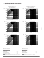
11.4 Campo di impiego con R134a - compressori serie Q, S e V
Application range with R134a - Q, S and V series compressors
Temperatura di aspirazione 20°C
Suction temperature 20°C
tc °C
Surriscaldamento in aspirazione 20K
Suction superheating 20K
tc °C
70
70
100%
100%
60
60
50
50
40
40
30
30
20
20
-30
tc °C
-20
-10
te °C
0
+10
-30
+20
tc °C
70
-20
-10
te °C
0
+10
+20
0
+10
+20
70
50%
60
50
50
40
40
30
30
20
FTEC02-03
50%
60
20
-30
-20
-10
te °C
0
+10
-30
+20
temperatura ambiente
massima temperatura della testata
massima temperatura dell’olio
massima pressione di compressione
Application data:
ambient temperature
maximum head temperature
maximum oil temperature
maximum discharge pressure
30°C
130°C ±5K
70°C
27 bar
30°C
130°C ±5K
70°C
27 bar
additional cooling with head fan motor
Q = 2700 m3/h for S series compressors
Q = 2950 m3/h for V series compressors
raffreddamento supplementare con motoventilatore in testa
Q = 2700 m3/h per compressori serie S
Q = 2950 m3/h per compressori serie V
Istruzioni di servizio
-10
te °C
te = evaporating temperature
tc = condensing temperature
te = temperatura di evaporazione
tc = temperatura di condensazione
Condizioni di impiego:
-20
16
Operating instructions
11.5 Campo di impiego con R134A - compressori serie Z
Application range with R134A - Z series compressors
Temperatura di aspirazione 20°C
Suction temperature 20°C
tc °C
Surriscaldamento in aspirazione 20K
Suction superheating 20K
tc °C
70
70
100%
100%
60
60
50
50
40
40
30
30
20
20
-30
tc °C
-20
-10
te °C
0
+10
-30
+20
tc °C
70
-20
FTEC02-03
0
+10
+20
0
+10
+20
0
+10
+20
70
66%
66%
60
60
50
50
40
40
30
30
20
20
-30
tc °C
-10
te °C
-20
-10
te °C
0
+10
-30
+20
tc °C
70
-20
-10
te °C
70
33%
33%
60
60
50
50
40
40
30
30
20
20
-30
-20
-10
te °C
0
+10
-30
+20
temperatura ambiente
massima temperatura della testata
massima temperatura dell’olio
massima pressione di compressione
Application data:
ambient temperature
maximum head temperature
maximum oil temperature
maximum discharge pressure
30°C
130°C ±5K
70°C
27 bar
30°C
130°C ±5K
70°C
27 bar
additional cooling with head fan motor; Q = 2950 m3/h
raffreddamento supplementare con motoventilatore in testa; Q = 2950 m3/h
Istruzioni di servizio
-10
te °C
te = evaporating temperature
tc = condensing temperature
te = temperatura di evaporazione
tc = temperatura di condensazione
Condizioni di impiego:
-20
17
Operating instructions
11.6 Campo di impiego con R134A - compressori serie W
Application range with R134A - W series compressors
Temperatura di aspirazione 20°C
Suction temperature 20°C
tc °C
Surriscaldamento in aspirazione 20K
Suction superheating 20K
tc °C
70
70
100%
100%
60
60
50
50
40
40
30
30
20
20
-30
tc °C
-20
-10
te °C
0
+10
-30
+20
tc °C
70
-20
0
+10
+20
0
+10
+20
0
+10
+20
70
75%
60
60
50
50
40
40
30
30
20
FTEC02-03
75%
20
-30
tc °C
-10
te °C
-20
-10
te °C
0
+10
-30
+20
tc °C
70
-20
-10
te °C
70
50%
50%
60
60
50
50
40
40
30
30
20
20
-30
-20
-10
te °C
0
+10
-30
+20
temperatura ambiente
massima temperatura della testata
massima temperatura dell’olio
massima pressione di compressione
Application data:
ambient temperature
maximum head temperature
maximum oil temperature
maximum discharge pressure
30°C
130°C ±5K
70°C
27 bar
30°C
130°C ±5K
70°C
27 bar
additional cooling with head fan motor; Q = 3660 m3/h
raffreddamento supplementare con motoventilatore in testa; Q = 3660 m3/h
Istruzioni di servizio
-10
te °C
te = evaporating temperature
tc = condensing temperature
te = temperatura di evaporazione
tc = temperatura di condensazione
Condizioni di impiego:
-20
18
Operating instructions
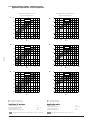
11.7 Campo di impiego con R22 - compressori serie Q, S e V
Application range with R22 - Q, S and V series compressors
Temperatura di aspirazione 20°C
Suction temperature 20°C
tc °C
Surriscaldamento in aspirazione 20K
Suction superheating 20K
tc °C
70
70
100%
100%
60
60
50
50
40
40
30
30
20
20
-30
tc °C
-20
-10
te °C
0
+10
-30
+20
tc °C
70
-20
0
+10
+20
0
+10
+20
70
50%
FTEC02-03
-10
te °C
50%
60
60
50
50
40
40
30
30
20
20
-30
-20
-10
te °C
0
+10
-30
+20
temperatura ambiente
massima temperatura della testata
massima temperatura dell’olio
massima pressione di compressione
Application data:
ambient temperature
maximum head temperature
maximum oil temperature
maximum discharge pressure
30°C
130°C ±5K
70°C
27 bar
30°C
130°C ±5K
70°C
27 bar
additional cooling with head fan motor
Q = 2700 m3/h for S series compressors
Q = 2950 m3/h for V series compressors
raffreddamento supplementare con motoventilatore in testa
Q = 2700 m3/h per compressori serie S
Q = 2950 m3/h per compressori serie V
Istruzioni di servizio
-10
te °C
te = evaporating temperature
tc = condensing temperature
te = temperatura di evaporazione
tc = temperatura di condensazione
Condizioni di impiego:
-20
19
Operating instructions
11.8 Campo di impiego con R22 - compressori serie Z
Application range with R22 - Z series compressors
Temperatura di aspirazione 20°C
Suction temperature 20°C
tc °C
Surriscaldamento in aspirazione 20K
Suction superheating 20K
tc °C
70
70
100%
100%
60
60
50
50
40
40
30
30
20
20
-30
tc °C
-20
-10
te °C
0
+10
-30
+20
tc °C
70
-20
0
+10
+20
0
+10
+20
0
+10
+20
70
66%
60
60
50
50
40
40
30
30
20
FTEC02-03
66%
20
-30
tc °C
-10
te °C
-20
-10
te °C
0
+10
-30
+20
tc °C
70
-20
-10
te °C
70
33%
33%
60
60
50
50
40
40
30
30
20
20
-30
-20
-10
te °C
0
+10
-30
+20
temperatura ambiente
massima temperatura della testata
massima temperatura dell’olio
massima pressione di compressione
Application data:
ambient temperature
maximum head temperature
maximum oil temperature
maximum discharge pressure
30°C
130°C ±5K
70°C
27 bar
30°C
130°C ±5K
70°C
27 bar
additional cooling with head fan motor; Q = 2950 m3/h
raffreddamento supplementare con motoventilatore in testa; Q = 2950 m3/h
Istruzioni di servizio
-10
te °C
te = evaporating temperature
tc = condensing temperature
te = temperatura di evaporazione
tc = temperatura di condensazione
Condizioni di impiego:
-20
20
Operating instructions
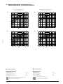
11.9 Campo di impiego con R22 - compressori serie W
Application range with R22 - W series compressors
Temperatura di aspirazione 20°C
Suction temperature 20°C
Surriscaldamento in aspirazione 20K
Suction superheating 20K
tc °C 70
tc °C
70
100%
100%
60
60
50
50
40
40
30
30
20
20
-30
-20
-10
te °C
0
+10
-30
+20
tc °C
tc °C 70
-20
0
+10
+20
0
+10
+20
0
+10
+20
70
75%
FTEC02-03
-10
te °C
75%
60
60
50
50
40
40
30
30
20
20
-30
-20
-10
te °C
0
+10
+20
-30
tc °C
tc °C 70
-20
-10
te °C
70
50%
50%
60
60
50
50
40
40
30
30
20
20
-30
-20
-10
te °C
0
+10
-30
+20
temperatura ambiente
massima temperatura della testata
massima temperatura dell’olio
massima pressione di compressione
Application data:
ambient temperature
maximum head temperature
maximum oil temperature
maximum discharge pressure
30°C
130°C ±5K
70°C
27 bar
30°C
130°C ±5K
70°C
27 bar
additional cooling with head fan motor; Q = 2950 m3/h
raffreddamento supplementare con motoventilatore in testa; Q = 2950 m3/h
Istruzioni di servizio
-10
te °C
te = evaporating temperature
tc = condensing temperature
te = temperatura di evaporazione
tc = temperatura di condensazione
Condizioni di impiego:
-20
21
Operating instructions
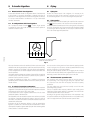
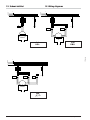
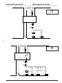
12. Schemi elettrici
12. Wiring diagrams
I
I
L1
L2
L3
L1
L2
L3
N
N
F
F
F
TR
L3
F
N
L3
TR3
B
3 ph
D.O.L.
A
B
3 ph
P.W.S.
FTEC02-03
A
N
TR4
I
L1
L2
L3
N
F
F
L3
TR2
TR
A
Istruzioni di servizio
B
N
TR1
3 ph
/Δ
22
Operating instructions
Schemi elettrici per testa
Wiring diagrams for
head
L
B
A
HS
L
1
3 ph
D.O.L.
11
2
K1
N
12
14
PT
DT
DP
P
CC
LP1
TR
CC1
CC2
FTEC02-03
N
L
A
B
HS
L
1
2
11
3 ph
P.W.S.
K1
N
12
14
PT
DT
DP
P
TR1
TR2
T1
TR1
TR2
CC
LP1
N
Istruzioni di servizio
TR
T1
TR2
CC1
23
CC2
Operating instructions
Schemi elettrici per testa
Wiring diagrams for
head
L
B
A
3 ph
/Δ
HS
1
L
2
11
K1
N
14
12
PT
DT
DP P
TR
TR3
T2
TR4
TR4
LP1
T2
CC
TR1
TR
T2
TR4
CC1
CC2
TR3
FTEC02-03
N
TR4
Legenda
A-B
CC
CC1
CC2
DP
DT
HS
K1
L
LP1
N
PT
TR
TR1
TR2
TR3
TR4
T1
T2
Legend
A-B
CC
CC1
CC1
DP
DT
HS
K1
L
LP1
N
PT
TR
TR1
TR2
TR3
TR4
T1
T2
terminali dei termistori
attuatore del controllo di capacità
bobina della 1a testa
bobina della 2a testa
pressostato
termostato
sensore temperatura di compressione
modulo elettronico KRIWAN
fase della rete di alimentazione
spia intervento termistori
neutro
protettore termoamperometrico
teleruttore principale
teleruttore di avviamento PWS 50%
teleruttore di avviamento PWS 100%
teleruttore di avviamento
teleruttore di avviamento Δ
relay temporizzato per avviamento PWS (0.5÷1 secondo)
relay temporizzato per avviamento - Δ (1÷2 secondi)
Non alimentare direttamente
i terminali A - B dei termistori
Istruzioni di servizio
thermistor terminals
capacity control actuator
coil of 1st
head
head
coil of 2nd
pressure switch
thermostat
head temperature sensor
KRIWAN electronic module
phase of electrical net
thermistor warning lamp
neutral
overload protector
main contactor
PWS 50% start contactor
PWS 100% start contactor
start contactor
Δ start contactor
time delay relay for PWS (0.5÷1 second)
time delay relay for - Δ start(1÷2 second)
Do not feed directly terminals
A - B of the thermistors
24
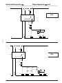
Operating instructions
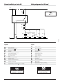
Wiring diagrams for US head
Schemi elettrici per testa US
L3
B
A
3 ph
D.O.L.
HS
L
1
N
12
11
2
14
DT
DP
P
RR
RR
LP1
TR
US
FTEC02-03
N
L3
B
A
3 ph
PWS
HS
L
1
N
12
11
2
14
DT
DP
RR
LP1
N
Istruzioni di servizio
TR3
P
TR3
T5
TR4
TR3
TR4
T5
25
TR4
RR
US
Operating instructions
Wiring diagrams for US head
Schemi elettrici per testa US
L3
B
A
HS
L
3 ph
/Δ
1
N
11
2
12
14
DT
DP
P
TR
LP1
T5
TR2
TR2
TR2
T5
RR
TR1
TR3
TR4
T5
TR1
US
FTEC02-03
N
RR
TR1
Legenda
A-B
CC
CC1
CC2
DP
DT
HS
K1
L
LP1
N
PT
TR
TR1
TR2
TR3
TR4
T1
T2
Legend
A-B
CC
CC1
CC1
DP
DT
HS
K1
L
LP1
N
PT
TR
TR1
TR2
TR3
TR4
T1
T2
terminali dei termistori
attuatore del controllo di capacità
bobina della 1a testa
bobina della 2a testa
pressostato
termostato
sensore temperatura di compressione
modulo elettronico KRIWAN
fase della rete di alimentazione
spia intervento termistori
neutro
protettore termoamperometrico
teleruttore principale
teleruttore di avviamento PWS 50%
teleruttore di avviamento PWS 100%
teleruttore di avviamento
teleruttore di avviamento Δ
relay temporizzato per avviamento PWS (0.5÷1 secondo)
relay temporizzato per avviamento - Δ (1÷2 secondi)
Non alimentare direttamente
i terminali A - B dei termistori
Istruzioni di servizio
thermistor terminals
capacity control actuator
head
coil of 1st
coil of 2nd
head
pressure switch
thermostat
head temperature sensor
KRIWAN electronic module
phase of electrical net
thermistor warning lamp
neutral
overload protector
main contactor
PWS 50% start contactor
PWS 100% start contactor
start contactor
Δ start contactor
time delay relay for PWS (0.5÷1 second)
time delay relay for - Δ start(1÷2 second)
Do not feed directly terminals
A - B of the thermistors
26
Operating instructions
FTEC02-03
13. Modelli delle teste US e parti di ricambio
13. US head models and spare parts
T00SK250100 Assieme testa US per compressori serie F e S
T00SK250100 US head kit for compressor series F and S
parti di ricambio disponibili:
available spare parts:
• T00EC1010 valvola elettromagnetica, senza bobina
• T00EC1210 bobina 10 W, 230 V, 50-60 Hz
• T00EC1206 bobina 10 W, 110 V, 50-60 Hz
• T00S3631032 guarnizione testa US / corpo compressore
• T00S4451094 guarnizione valvola elettromagnetica / testa US
• T00EC1010 solenoid valve, without coil
• T00EC1210 coil 10 W, 230 V, 50-60 Hz
• T00EC1206 coil 10 W, 110 V, 50-60 Hz
• T00S3631032 gasket US head / compressor body
• T00S4451094 gasket solenoid valve / US head
T00SK250150 Assieme testa US per compressori serie Q
T00SK250150 US head kit for compressor series Q
parti di ricambio disponibili:
available spare parts:
• T00EC1018 valvola elettromagnetica, senza bobina
• T00EC1210 bobina 10 W, 230 V, 50-60 Hz
• T00EC1206 bobina 10 W, 110 V, 50-60 Hz
• T00S2451032 guarnizione testa US / corpo compressore
• T00S4031094 guarnizione valvola elettromagnetica / testa US
• T00EC1018 solenoid valve, without coil
• T00EC1210 coil 10 W, 230 V, 50-60 Hz
• T00EC1206 coil 10 W, 110 V, 50-60 Hz
• T00S2451032 gasket US head / compressor body
• T00S4031094 gasket solenoid valve / US head
T00SK250200 Assieme testa US per compressori serie V, Z e W
T00SK250200 US head kit for compressor series V, Z and W
parti di ricambio disponibili:
available spare parts:
• T00EC1005 valvola elettromagnetica, senza bobina
• T00EC1210 bobina 10 W, 230 V, 50-60 Hz
• T00EC1206 bobina 10 W, 110 V, 50-60 Hz
• T00S8701032 guarnizione testa US / corpo compressore
• T00S6401094 guarnizione valvola elettromagnetica / testa US
• T00EC1005 solenoid valve, without coil
• T00EC1210 coil 10 W, 230 V, 50-60 Hz
• T00EC1206 coil 10 W, 110 V, 50-60 Hz
• T00S8701032 gasket US head / compressor body
• T00S6401094 gasket solenoid valve / US head
Istruzioni di servizio
27
Operating instructions
FRASCOLD spa
FTEC02-03
Via Barbara Melzi 105
I-20027 Rescaldina (MI)
ITALY
phone +39-0331-7422.01
fax +39-0331-576102
http://www.frascold.it
e-mail: [email protected]
Istruzioni di servizio
28
Operating instructions