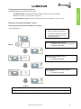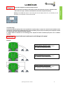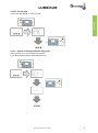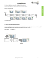
1
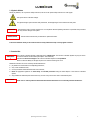
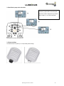
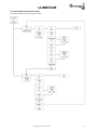
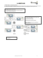
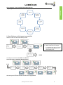
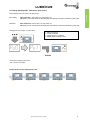
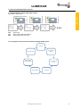
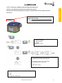
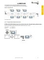
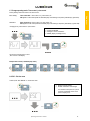
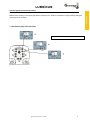
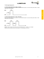
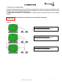
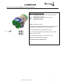
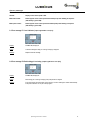
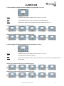
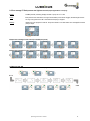
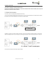
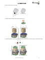
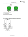
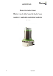
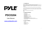
Operating Instructions Lubricus Lubrication System LUB - M (24 VDC) Operating Instructions: LUB- M Table of Contents 1) General Information 1.1 Warning 1.2 Scope of supply 1.3 Overview – the Lubricus M Lubrication System 1.4 Symbols and notes 1.5 Intended use 1.6 Liability and extent of guarantee 4 4 4 4 5 5 6 2) Safety Information 2.1 General safety information 2.2 Transport and storage 2.3 Installation 2.4 Maintenance 7 7 8 8 8 3) Lubricus M - General information 3.1 Definition of terms 3.2 Display & Actuation Pad 3.3 Identification pump units and outlets 3.4 Grease cartridge Lubricus M 9 9 9 10 10 4) Function/Principle 4.1 Basic operation 4.2 Lubricus M operation menu (overview) 4.3 Start: control panel 4.4 Default indication control panel (time control) 4.5 Quick Check – back pressure control 11 11 12 13 13 14 5) Pro Program – time controlled lubrication intervals 5.1 Enter PIN 5.2 Input pause time and amount of lubricant 5.3 ESC – Exit the menu 5.4 CLr – delete error messages 5.5 FIL – first start-up, venting the pump 5.6 Change PIN 5.7 Change Feedback (Pump function control) 5.8 Change operating mode: Time control / pulse control 15 15 16 18 18 19 20 20 21 6) Pro Program – pulse controlled lubrication intervals 6.1 Default indication control panel (pulse control) 6.2 Enter PIN 6.3 CLr – delete error messages 6.4 FIL – first start-up, venting the pump 6.5 Change PIN 6.6 Change Feedback (Pump function control) 6.7 Change operating mode: Time control / pulse control 6.8 ESC – Exit the menu 22 22 23 23 24 25 25 26 26 7) Pulse signals to activate the outlets 7.1 Identification pump units and outlets 7.2 Pulse signals pump unit 1 7.3 Pulse signals pump unit 2 7.4 Pulse signals pump unit 3 7.5 Pulse signals pump unit 4 7.6 Pulse signals pump unit 5 7.7 pulse control - acceptable Design 27 27 28 28 29 29 30 31 Operating Instructions: LUB-M Pulse control 2 Time control Contents 2 8) Communication interface (M12x1 connector) Lubricus M 32 9) Errors, Messages 9.1 Error message E1: Level indicator 9.2 Error message E2: Red locking pin is missing 9.3 Error message E3: Pump unit works too slowly 9.4 Error message E4: Internal electrical fault 9.5 Error message E7: Back pressure too high/over-current 33 33 33 34 34 35 10) Master PIN 35 11) Service Lubricus M 11.1 Readout of the device memory 11.2 replacement of grease cartridge 36 36 37 12) Mounting Lubricus M 40 13) Technical data 41 14) Disposal 41 Operating Instructions: LUB-M 3 1) General information Thank you very much for choosing the Lubricus M Lubrication System. Please ensure you familiarise yourself with the safety instructions before using the pump and accessories supplied. This manual contains important safety information. The Lubricus Lubrication System is a very compact lubrication pump for oil and grease up to NLGI class 2. The Lubricus type LUB-M is made for a 24 VDC power supply and requires a mains connection. The lubricant reservoir (1500 cm³) is in a rigid, disposable cartridge. Supply pressure is <70 bar. Depending on the model, the Lubricus Lubrication System has 2, 4, 6, 8 or 10 outlets. 1.1 Warning The Lubricus Lubrication System is designed for use in normal industrial environments, but not for use in or on motor vehicles. Use only original Lubricus spare parts and accessories (cartridges, fittings, connectors, tubes and battery packs). 1.2 Scope of supply The scope of supply may vary from country to country. Standard supply includes: the Lubricus M Lubrication System tube connector attached to the outlet(s) for medium-pressure PA tube 6 x 4 (Ø 6mm outer and Ø 4mm inner diameter) Operating Instructions 1.3 Overview – the Lubricus M Lubrication System Installing the Lubricus Lubrication System is simple. These instructions should help you to install your pump swiftly and easily, and to quickly learn the basics. Actuation magnet Housing/covering für Faltenbalg Actuation pad Outlets Communication interface (Output M12x1) Please note! Unused outlets should not be closed! Operating Instructions: LUB-M 4 1.4 Symbols & Notes Please pay attention, not only to these safety instructions, but also to the special safety instructions on other pages. This symbol warns of electrical voltage. This general danger symbol denotes safety instructions, the disregarding of which could lead to bodily harm. This heading is used if incorrect compliance or non-compliance with the Operating Instructions or specified work procedures etc. may result in damage of the system. Attention ! Please note! This term will be used to draw your attention to special information. ! Instructions attached directly to the machine must be strictly followed and kept in clearly legible condition! 1.5 Intended Use Attention ! The Lubricus Lubrication System is only approved for industrial use. The Lubricus Lubrication System may only be used in accordance with the Technical Data (see chapter “Technical Data”). Unauthorised structural changes to the Lubricus Lubrication System are not permitted. We do not assume liability for damages to persons or machines resulting from such. Additional instructions for use in conformity with the intended use: pay attention to all information in the Operating Instructions; carry out all maintenance work; use only Gruetzner GmbH lubrication tubes and connectors; follow all appropriate regulations for work safety and accident prevention during the entire lifespan of the Lubricus Lubrication System; only qualified and authorized personnel should carry out work of any kind on the Lubricus Lubrication System. Attention ! Other uses or uses beyond those described above shall be deemed as not in conformity with the intended use. Operating Instructions: LUB-M 5 1.6 Liability and extent of guarantee Proper functioning of the Lubricus Lubrication System can only be achieved through use of recommended lubricants from the original Lubricus range of accessories, and by observation of all installation, operation and maintenance instructions. Gruetzner GmbH excludes all liability if these instructions are not observed. Gruetzner GmbH grants guarantees concerning operating safety, reliability and performance only under the following conditions: assembly, installation, maintenance and repairs are carried out by qualified staff only; hazardous hot or cold machine parts must be shielded to prevent skin contact; the Lubricus Lubrication System must be used according to the Technical Data and instructions; the limit values stated in the Technical Data are under no circumstances to be exceeded; retrofitting and repair work on the Lubricus Lubrication System may only be carried out by the manufacturer; the lubrication system must be protected against damp and wet. If a lubricant that has not yet been tested for compatibility with the Lubricus Lubrication System be supplied or requested for use in the Lubricus Lubrication System by the purchaser/customer, the purchaser/customer undertakes the risk and responsibility. This product is subject to strict production controls and fulfils our company’s factory specifications. However, guarantee of testing of each individual case cannot be given due to the numerous factors involved. We therefore strongly recommend that test runs be carried out. All liability is excluded. The Lubricus Lubrication System lubricant cartridge has been constructed and produced for one-time use only. Multiple use of the lubricant cartridge is not envisaged. After being used once, the lubricant cartridge is to be completely replaced; refilling is not permitted. Noncompliance will lead to nullification of the guarantee. For guarantee conditions see the sales and delivery conditions of Gruetzner GmbH Operating Instructions: LUB-M 6 2) Safety Information Basic information, which must be followed during assembly, operation and maintenance, is listed as follows. These Operating Instructions must be read by all installation and operation staff before assembly and operation, and must be permanently available on site. All personnel involved in installation, maintenance and operation of the system are to read these instructions carefully before beginning assembly and operation. 2.1 General safety information 2.1.1 Qualification and training of personnel All operation, maintenance, service and installation personnel must be appropriately qualified for this work. Responsibility and supervision of the personnel must be clearly defined by the end user. If staff do not have the necessary knowledge, they must be trained and instructed. The end user must ensure that staff have completely understood the contents of the Operating Instructions. 2.1.2 Danger of non-compliance with the safety instructions Non-compliance with the safety information can be dangerous for people, environment and machines. Noncompliance with the safety information can mean the loss of any or all damage claims. In certain cases, non-compliance can, for example, lead to the following hazards: malfunction of important system functions. malfunction of prescribed methods of maintenance and servicing. danger to people due to electrical, mechanical and chemical effects. danger to the environment due to leakage of dangerous substances. 2.1.3 Safety information for end user / operating staff Moving, rotating, hot or cold machine parts are to be securely shielded on site to prevent accidental contact. The shielding on moving or rotating parts is not to be removed. Leakages of dangerous materials are to be removed in such a way as not to endanger people or the environment. Legal regulations are to be complied with. Electrical hazards are to be eliminated. 2.1.4. Safety information for maintenance, inspection and assembly work All maintenance, inspection and installation work may only be carried out by trained specialists who have been informed appropriately by carefully studying the Operating Instructions. All work must only be carried out when the machine is witched off and while wearing appropriate protective clothing. Always comply with the procedures for switching off as described in the Operating Instructions. All safety and protective equipment must be replaced immediately after completing work. Environmentally hazardous substances must be disposed of in accordance with local regulations. Secure the system during maintenance and repair work against intentional or unintentional operation. Dispose of lubricants in accordance with the safety data sheets of the lubricant manufacturer. 2.1.5 Unauthorised modification and manufacture of spare parts Modification and alteration of the system is not permitted. Original spare parts and accessories authorised by the manufacturer are for safety purposes. Using other parts can result in loss of liability for claims resulting out of this. Grützner GmbH does not guarantee and is not liable for components retrofitted by the end user. 2.1.6 Prohibited methods of operation Operational security of the Lubricus Lubrication System is only guaranteed if it is operated in accordance with the Operating Instructions. The limit values listed in the Technical Data are under no circumstances to be exceeded. Operating Instructions: LUB-M 7 2.1.7 General hazard warning All components of the system are designed in accordance with the prevailing regulations of the construction of technical machines regarding operational safety and accident prevention. Nevertheless, operation can lead to dangers for the user, third parties or other technical facilities. Therefore, the Lubricus Lubrication System may only be used for its intended purpose in technically fault-free condition. This may only be carried out under compliance with the safety regulations and the Operating Instructions. Therefore, please regularly check the Lubricus Lubrication System and its attachments for possible damage or leaks. 2.2 Transport and storage Use suitable lifting gear for transport. Do not throw or expose the Lubricus Lubrication System to heavy buffeting. Store the Lubricus Lubrication System in a cool and dry place to avoid corrosion of the system’s individual parts. Comply with valid safety and accident prevention instructions when transporting. Wear suitable protection clothing if necessary! 2.3 Installation The following conditions have to be satisfied during the installation of this Lubricus Lubrication System so that it can be assembled to a complete machine without affecting the health and safety of humans. To prevent the formation of condensation, the housing of the Lubricus Lubrication System should not be exposed to direct sunlight or radiant heat. The Lubricus Lubrication System must be protected against damp and wet. We strongly recommend that the lubrication system be enclosed in a housing. Lubricus Lubrication Systems should never be exposed to outside weather conditions. If using outdoors, ensure the system has suitable protection (e.g. housing) and never use this product in or under water. 2.3.1 Electrical connection Only a qualified electrician should connect the power supply! Connection of electrical components is to be carried out professionally. Compare the voltage details with the existing power supply voltage! 2.4 Maintenance Disconnect the system from the mains before starting with maintenance or repair work. Maintenance and repair work may only be done with the system completely switched off. Check the surface temperature of the Lubricus Lubrication System to avoid burns. Always wear heat-resistance gloves! Ensure the system cannot be restarted during maintenance and repair work! Operating Instructions: LUB-M 8 3) Lubricus M – General Information Lubricus M 3.1 Definition of terms Lubricus M is designed for applications with minimal amounts of lubricant: o Depending on the configuration Lubricus M is available with up to 5 pump units (P1, P2, P3, P4, P5), each with 2 outlets. o 1 pump unit is the housing for 2 piston pumps. 1 pump unit is dispensing equal quantities from both outlets. o Minimum quantity lubrication means the controlled and efficient supply of a lubrication point with selected, high performance lubricants o Run = back pressure control – preventive check on a lubrication point: The measurement of the back pressure is done during the pumping process and the result will be shown on the display. The displayed value is a first orientation over the pressure range. 3.2 Actuation Pad Pump unit P1 … P5: Error messages (ALARM): Operating Instructions: LUB-M display green LED display red LED 9 3.3 Identification pump units and outlets Each active pump body (P1, P2, P3, P4, P5) is indicated by a green LED on the control panel. Each active outlet is displayed during a function with a number (1 or 2) on the control panel. 3.4 Grease cartridge The lubricant reservoir (1500 cm³) is in a disposable grease cartridge. Operating Instructions: LUB-M 10 4) Function/Principle After starting, the integrated pump transports the lubricant to the outlets according to the settings that have been made. The integrated electronics control and monitor the amount of lubricant and the time intervals between lubrications. The Lubricus M Type uses a four-pin socket to connect a M12X1 plug allowing communication with the machine controller. An external 24 VDC power supply is used to switch ON and OFF (voltage 24 VDC -5% / +10%), supplied to PIN 1. When voltage is supplied the lubrication pump is in operating condition. If there are no errors (Pump OK) the input voltage will be transferred to the output signal (PIN 4) indicating all is OK. Once the voltage supply to PIN 1 is stopped (switched OFF), the pump rests and saves the current operating conditions in memory. When the pump is turned back on the saved operating conditions will be continued. PIN 4 relays the operating condition. 4.1 Basic operation All changes to the settings are made with the actuation magnet (ventilation lock). Open the ventilation lock (turn clockwise to OPEN) and remove it from the cover. The tip of the ventilation lock is your programming key. If there are no desired changes to the settings, please set the actuation magnet back at its place and close the ventilation lock (turn counter clockwise to CLOSE). Programming Lubricus M SELECT: Change settings - touch the operating pad with the actuation magnet ENTER: Confirmation of all changes - touch the actuation pad actuation magnet. The display flashes 2 times for confirmation TIMEOUT: If no interaction takes place for a period, the device automatically returns to the previous display mode. Operating Instructions: LUB-M 11 4.2 Lubricus M operation menu (overview) Two modes are possible: „time control“ and „pulse control“ Operating Instructions: LUB-M 12 4.3 Start: control panel. Apply operating voltage Softwareversion n01 … n99 Operating mode Operating mode Time control Pulse Control 4.4 Default indication control panel (time control) SELECT: Change settings - touch the operating pad with the actuation magnet ENTER: Confirmation of all changes - touch the actuation pad actuation magnet. If no interaction takes place for a period, the device automatically returns to the previous display mode. Basic menu in time mode: On: run: Pro: ESC: Operating mode – time control Run = back pressure control – preventive check on a lubrication point: The measurement of the back pressure is done during the dispensing pumping process and the result will be shown on the display. The displayed value is a first orientation over the pressure range. Other functions, PIN code protected Key to leave and return to the main menu Operating Instructions: LUB-M 13 4.5 Quick Check – back pressure control For test and sample purposes the installed lubrication pump can easily be used to dispense small amounts of lubricant. For this purpose, the available pressure between the lubrication point and pump is measured. The value displayed is the back pressure in bar. SELECT: Change settings ENTER: Confirmation of all changes If no interaction takes place for a period, the device automatically returns to the previous display mode Selection of pump body by SELECT Display shows selected pump body (green LED) Confirmation by ENTER Result is shown on display (multiple repetitions possible by ENTER) Remark: outlets of one pump unit are dispensing lubricant alternately Select other pump unit or timeout: leave the menu Operating Instructions: LUB-M 14 5) Pro Program – time controlled lubrication intervals The „pro program“ of the time mode contains the following editable options: Time control Enter PIN Change operating mode (time/pulse) Input delivery rates and pasue times Change feedback ESC: exit the menu CLr: delete error messages Change PIN FIL: Deaerate the pump 5.1 Enter PIN: Access to Pro Program is protected (PIN) Selection of other menu items with PIN entry possible. SELECT: Change settings ENTER: Confirmation of all changes If no interaction takes place for a period, the device automatically returns to the previous display mode The settings are performed with „ENTER“ and „SELECT“. The factory setting is: 000 (Master PIN siehe Service) After entering the the PIN the lubrication intervals can be programmed. Operating Instructions: LUB-M 15 5.2 Input pause time and amount of lubricant The following settings can be made for each pump body. Time control H: TIME (pause time): time between the lubrication intervals in hours (1 to 240 h are possible) Attention: If H: TIME = 0 it is not possible to input cycles. C: CYCLE (number of cycles) = amount of lubricant per interval (1 to 30 possible, 1 cycle = 0,15 cm³) Pump units can be turned off by setting C: CYCLE = 0 Factory setting for every pump unit: H: TIME = 4h, C: CYCLE = 1 step-by-step approach: SELECT: Change settings ENTER: Confirmation of all changes If no interaction takes place for a period, the device automatically returns to the previous display mode Select pump body (P1-P5) via SELECT indicated by a green LED on the control panel. Confirmation with ENTER Input pause time (H: TIME) via SELECT max. 240 h possible Confirmation with ENTER Input number of cycles (C: Cycle) via SELECT, max. 30 possible Confirmation with ENTER Select other pump unit or timeout: exit the menu. Important: Changes of the parameters are only applied by confirming. Operating Instructions: LUB-M 16 Lubricus M is designed for minimum quantity lubrication. The microprocessor calculates from the inputs of pause time and number of cycles a comparison value. If this value is too high, a reduction in the lifetime of Lubricus M is accepted consciously. Warning: The ALARM LED flashes on the control panel and the display shows "InF" (for information) for 10s. During this 10s, the operation of Lubricus M is blocked. . Acceptable Design: The specified lubricant quantity refers to the expected life of a piston pump or a pump unit. A service for the verification of the performance of Lubricus M is recommended. Service interval is 65,000 cycles per pump unit. 65,000 cycles correspond to 10.000 cm³ lubricant. See service: Readout of the device memory. If a higher demand for lubricant at one lubricating point is required, the outlets of different pump units can be combined externally. Please note! unused outlets must remain open to avoid damage to the pump! ! Examples: 1 outlet supplying 1 lubrication point: Allowed amount of lubricant for 1 lubrication point = max. 5,000 cm³ at 50 bar back pressure 2 outlets supplying 1 lubrication point: Allowed amount of lubricant for 1 lubrication point = max. 10,000 cm³ at 50 bar back pressure 4 outlets supplying 1 lubrication point: Allowed amount of lubricant for 1 lubrication point = max. 20,000 cm³ at 50 bar back pressure Operating Instructions: LUB-M 17 Time control Attention !! 5.3 ESC – Exit the menu Confirm „ESC“ with "ENTER" => exit to main menu. Time control 5.4 CLr – delete error messages and delete filling cycles With Confirmation of „CLr“ error messages will be deleted. In „FIL“-Modus the filling operation will be stopped with „CLr“. Operating Instructions: LUB-M 18 5.5 FIL – first start-up, venting the pump und filling of lubrication lines Attention: Lubricus M lubrication pumps must be filled at initial operation. Each pump unit must be filled separately. The operation is completed when lubricant is visible at the outlet. Attention! Time control First start-up: Prefill housing inlet with 50 ml of suitable lubricant (same grease type as content of cartridge) Attention: Low level indicator in the inlet must not be damaged. Then place grease cartridge and start FIL function. . Select „FIL“ Confirm with ENTER Select pump body ENTER Delete with CLr (Clear) FIL means that the outlet of each pump unit is 15 times active. Total time of FIL / pump unit: about 5 minutes This function can also be used to pre-fill tubes. 15 cycles with 0,15cm³ = about. 2 cm³ Delete with CLr (Clear) Select other pump units with: Pro PIN FIL or timeout => exit the menu Operating Instructions: LUB-M 19 5.6 Change PIN , factory setting PIN: 000 (Master PIN see Service) In the menu point „PIN“ you can change the PIN for the access of the PRO-Menues. Example: Change PIN to 222 Time control The new PIN is saved. 5.7 Change Feedback (Pump function control) Feedback = Pump function control: During the function of the pump (about 7 s) the output signal at PIN 4 is switching from High (+ 20...30 VDC) to Low (0 V). By counting the signals of the pump function control there is a possibility to estimate the delivered quantity of lubricant and the remaining quantity in the lubricant reservoir (delivery rate per cycle =0,15 cm³). Factory setting: Alternative: F 1 = Feedback “on” F 0 = Feedback “off” Operating Instructions: LUB-M 20 5.8 Change operating mode: Time control / pulse control Basic setting: Time control Pu0 = Time control „on“, pulse control „off“ ON appears on the control panel and activated pump units flashing in sequence (indicated by a green LED). Alternative: Pulse Control Pu1 = Pulse control „on“, time control „off“ PUL appears on the control panel and installed pump units flashing in sequence (indicated by a green LED). Changing from „time control“ to „Pulse control“: Select Pu0 Function Confirm with ENTER Change Pu0 to Pu1 via SELECT ENTER (Display is blinking 2 times) Lubricus M ist changed to pulse control. „PUL“ is shown on the Display. Example Pulse control (5 installed pump units) Operating Instructions: LUB-M 21 Time control Factory setting: Lubricus M works in the „time modus“. 6. pulse controlled lubrication intervals 6.1 Default indication control panel (pulse control) Basic menu in control mode: Pulse control PUL: Pro: ESC: pulse control Other functions, PIN code protected exit and return to the main menu The „pro program“ of the pulse mode contains the following editable options: Enter PIN ESC: exit the menu CLr: delete error messages Change operating mode (time/pulse FIL: Deaerate the pump Change Feedback Operating Instructions: LUB-M Change PIN 22 6.2 Enter PIN: Access to Pro Program is protected (PIN) Selection of other menu items with PIN entry possible. If no interaction takes place for a period, the device automatically returns to the previous display mode The settings are performed with „ENTER“ and „SELECT“. The factory setting is: 000 (Master PIN siehe Service) 6.3 CLr – delete error messages and delete filling cycles With Confirmation of „CLr“ error messages will be deleted. In „FIL“-Modus the filling operation will be stopped with „CLr“. Operating Instructions: LUB-M 23 Pulse control SELECT: Change settings ENTER: Confirmation of all changes 6.4 FIL – first start-up, venting the pump und filling of lubrication lines Attention: Lubricus M lubrication pumps must be filled at initial operation. Each pump unit must be filled separately. The operation is completed when lubricant is visible at the outlet. Pulse control First start-up: Attention! Prefill housing inlet with 50 ml of suitable lubricant (same grease type as content of cartridge) Attention: Low level indicator in the inlet must not be damaged. Then place grease cartridge and start FIL function. Select „FIL“ Confirm with ENTER Select pump body ENTER Delete with CLr (Clear) FIL means that the outlet of each pump unit is 15 times active. Total time of FIL / pump unit: about 5 minutes This function can also be used to pre-fill tubes. 15 cycles with 0,15cm³ = about 2 cm³ Delete with CLr (Clear) Select other pump units with: Pro PIN FIL or timeout => exit the menu Operating Instructions: LUB-M 24 6.5 Change PIN , factory setting PIN: 000 (Master PIN siehe Service) In the menu point „PIN“ you can change the PIN for the access of the PRO-Menues. Pulse control Example: Change PIN to 222 The new PIN is saved. 6.6 5.7 Change Feedback (Pump function control) Feedback = Pump function control: During the function of the pump (about 7 s) the output signal at PIN 4 is switching from High (+ 20...30 VDC) to Low (0 V). By counting the signals of the pump function control there is a possibility to estimate the delivered quantity of lubricant and the remaining quantity in the lubricant reservoir (delivery rate per cycle =0,15 cm³). Factory setting: Alternative: F 1 = Feedback “on” F 0 = Feedback “off” Operating Instructions: LUB-M 25 6.7 Change operating mode: Time control / pulse control Factory setting: Lubricus M works in the „time modus“. Time control Pu0 = Time control „on“, pulse control „off“ ON appears on the control panel and activated pump units flashing in sequence (indicated by a green LED). Alternative: Pulse Control Pu1 = Pulse control „on“, time control „off“ PUL appears on the control panel and installed pump units flashing in sequence (indicated by a green LED). Changing from „pulse control“ to „time control“: Select Pu1 Function Confirm with ENTER Change Pu1 to Pu0 via SELECT ENTER (Display is blinking 2 times) Lubricus M ist changed to time control. „ON“ is shown on the Display. Example time control (5 installed pump units) 6.8 ESC – Exit the menu Confirm „ESC“ with "ENTER" => exit to main menu. SELECT: Change settings ENTER: Confirmation of all changes If no interaction takes place for a period, the device automatically returns to the previous display mode Operating Instructions: LUB-M 26 Pulse control Basic setting: 7) Pulse signals to activate the outlets Indication in seconds, accuracy ± 0,2 s, time between two signals > 20 s 7.1 Identification pump units and outlets green LED shows active pump Operating Instructions: LUB-M 27 Pulse control Remark: During receiving a correct pulse signal at PIN 2, the display “PUL” flashes for confirmation. The green LED’s (indicating the pump units) are not now active. 7.2 Pulse signals pump unit 1 7.2.1 Pulse signals pump unit 1 – outlet 1 or outlet 2 Delivery rate per pulse signal: 0,15cm³, indication: 2s, start of delivery rate at outlet 1 or outlet 2. Outlets will be served alternately. Pulse control 7.2.2. Pulse signals pump unit 1 – outlet 1 or outlet 2 Delivery rate per pulse signal: 0,15cm³, indication: 2s, time between two signals > 20 s, start of delivery rate at outlet 1 or outlet 2. outlets will be served alternately. 7.3 Pulse signals pump unit 2 7.3.1 Pulse signals pump unit 2 - outlet 1 or outlet 2 Delivery rate per pulse signal: 0,15cm³, indication: 4s, start of delivery rate at outlet 1 or outlet 2. Outlets will be served alternately. 7.3.2 Pulse signals pump unit 2 - outlet 1 and outlet 2 Delivery rate per pulse signal: 0,15cm³, indication: 4s, time between two signals > 20 s, start of delivery rate at outlet 1 or outlet 2. Outlets will be served alternately Operating Instructions: LUB-M 28 7.4 Pulse signals pump unit 3 7.4.1 Pulse signals pump unit 3 – outlet 1 or outlet 2 Delivery rate per pulse signal: 0,15cm³, indication: 6s, start of delivery rate at outlet 1 or outlet 2. Outlets will be served alternately. Pulse control 7.4.2 Pulse signals pump unit 3 – outlet 1 and outlet 2 Delivery rate per pulse signal: 0,15cm³, indication: 6s, time between two signals > 20 s, start of delivery rate at outlet 1 or outlet 2. Outlets will be served alternately. 7.5 Pulse signals pump unit 4 7.5.1 Pulse signals pump unit 4 – outlet 1 or outlet 2 Delivery rate per pulse signal: 0,15cm³, indication: 8s, time between two signals > 20 s, start of delivery rate at outlet 1 or outlet 2. Outlets will be served alternately. 7.5.2 Pulse signals pump unit 4 – outlet 1 and outlet 2 Delivery rate per pulse signal: 0,15cm³, indication: 8s, time between two signals > 20 s, start of delivery rate at outlet 1 or outlet 2. Outlets will be served alternately. Operating Instructions: LUB-M 29 7.6 Pulse signals pump unit 5 7.6.1 Pulse signals pump unit 5 – outlet 1 or outlet 2 Delivery rate per pulse signal: 0,15cm³, indication: 10s, time between two signals > 20 s, start of delivery rate at outlet 1 or outlet 2. Outlets will be served alternately. Pulse control 7.6.2 Pulse signals pump unit 5 – outlet 1 and outlet 2 Delivery rate per pulse signal: 0,15cm³, indication: 10s, time between two signals > 20 s, start of delivery rate at outlet 1 or outlet Outlets will be served alternately. Remark: A new pulse signal can be started sooner if the feedback signal (F 1 = feedback „on”) is analyzed. Requirement: After reaching normal pump running there is a clear High signal for at least 5s. Operating Instructions: LUB-M 30 7.7 pulse control - acceptable Design The specified lubricant quantity refers to the expected life of a piston pump or a pump unit. A service for the verification of the performance of Lubricus M is recommended. Service interval is 65,000 cycles per pump unit. 65,000 cycles correspond to 10.000 cm³ lubricant. See service: Readout of the device memory. If a higher demand for lubricant at one lubricating point is required, the outlets of different pump units can be combined externally. Please note! Unused outlets must remain open to avoid damage to the pump! ! Examples: 1 outlet supplying 1 lubrication point: Allowed amount of lubricant for 1 lubrication point = max. 5,000 cm³ at 50 bar back pressure 2 outlets supplying 1 lubrication point: Allowed amount of lubricant for 1 lubrication point = max. 10,000 cm³ at 50 bar back pressure 4 outlets supplying 1 lubrication point: Allowed amount of lubricant for 1 lubrication point = max. 20,000 cm³ at 50 bar back pressure Operating Instructions: LUB-M 31 8) Communication interface (M12x1 connector) Lubricus M Connector PIN assignment M 12 x 1 PIN 1: PIN 2: PIN 3: PIN 4: Input voltage + 24 VDC (-5% to +10%), stabilized operating voltage 24 VDC, color brown Input pulse signal to activate pump unit, color white Ground (GND), color blue Output Signal, color black Details (all data refer to 24 VDC): Peak current Imax (during pump operation), approx. 350 mA, typically < 200 mA, Standby current (standby mode) < 50 mA, typically 20 mA The outlet signal (PIN4) can be charged with max. 100mA The peak current increases by the sampled output current: for example 350 mA + 100 mA = 450 mA Output signal (PIN 4): High (24VDC) = OK, LOW (0 V) = Error Warning: The exit is not short-circuit proof. A time delay fuse 1A is normally required. Operating Instructions: LUB-M 32 9) Errors, Messages Malfunctions will be recognized by the Lubricus electronics and shown on the display. General: Display on the control panel + LED Mode time control: Details appear on the control panel and activated pump units flashing in sequence (indicated by a green LED). Mode pulse control: Details appear on the control panel and installed pump units flashing in sequence (indicated by a green LED). 9.1 Error message E1: Level indicator (output signal PIN 4 = Low (0 V)) Display: ALARM LED, Display E1 Cause: Lubricant cartridge is empty or missing. Pumping is stopped! Remedy: Replace lubricant cartridge 9.2 Error message E2: Red locking pin is missing (output signal PIN 4 = Low (0 V)) Display: ALARM LED, Display E2 Cause: Red locking pin is missing. Pumping of all pump bodies is stopped Remedy: Put in the locking pin at the bottom of the housing. The error message is cleared automatically. Pump will continue to run as per active program. Operating Instructions: LUB-M 33 9.3 Error message E3: Pump unit works too slowly (output signal PIN 4 = Low (0 V)) Display: ALARM (red LED) is flashing, Display: Number of pump unit + E3 = 2E3 Cause: Low-voltage, pump unit does not work in specified time. Pumping is stopped! Remedy: Eliminate cause, delete error in the program Pro with Clr. Pump will continue to run. Example error message E3 time control (5 activated pump units) Example error message E3 pulse control (5 activated pump units) 9.4 Error message E4: Internal electrical fault (output signal PIN 4 = Low (0 V)) Display: ALARM (red LED) is flashing, Display: Number of pump unit + E4 = 2E4 Cause: Internal electrical fault. Pumping is stopped! Remedy: Delete error in the program Pro with Clr. Pump will continue to run. After another error message E4 send the pump for repair. Example error message E4 time control (5 activated pump units) Example error message E4 pulse control (5 activated pump units) Operating Instructions: LUB-M 34 9.5 Error message E7: Back pressure too high/over-current (output signal PIN 4 = Low (0 V)) Display: ALARM (red LED) is flashing, Display: Number of pump unit + E7 = 2E7 Cause: Back pressure was measured 3 x too high. The lubrication point could be clogged, the tube length could be too long or the grease is too stiff or has hardened. Pumping is stopped! Remedy: Delete error in the program Pro with Clr. Pump will continue to run. After another error message E4 send the pump for repair. Example error message E7 time control (5 activated pump units) Example error message E7 pulse control (5 activated pump units) 10) Master PIN: 485 The Master PIN – 4 – 8 – 5 - can be entered to access the Pro program. Operating Instructions: LUB-M 35 11) Service: Lubricus M Lubricus M ist is designed for minimum quantity lubrication. A service for the verification of the performance of Lubricus M recommended. Service interval is 65,000 cycles per pump unit. 65,000 cycles correspond to 10.000 cm³ lubricant. 11.1 Readout of the device memory The number of cycles can be determined by reading the device memory: Touch for 5s the operating pad (ENTER) with the programming key. Then remove the programming key. The display shows in sequence the number of cycles for every installed pump unit. The cycles are counted to 65,535. . P1 = 17.853 cycles Thereafter an overflow occurs. Number 1 appears in the display. The cycles are counted again, starting with number 1. 65.535 must be added to the displayed number. A service of the pump unit is strongly recommended in order to ensure the performance of Lubricus M. The only other service required is the change of grease cartridge. Operating Instructions: LUB-M 36 11.2 Service: Lubricus M – replacement of grease cartridge 1. Observe the safety instructions 2. Remove red locking pin (bottom of the housing) 3. Remove transparent cover: Attention: The internal components of the transparent cover are spring-loaded. Operating Instructions: LUB-M 37 4. Remove the green actuation magnet and lock press plate with red locking pin. Attention: The internal components of the transparent cover are spring-loaded. 5. Remove grease cartridge Operating Instructions: LUB-M 38 6. Remove protection from the new cartridge 7. Place the cartridge on the inlet, install the prepared transparent cover 8. Complete the installation of the housing by tightening the screws to a torque of 5 Nm, remove the locking pin, reinstall actuation magnet. Operating Instructions: LUB-M 39 9. Reinstall locking pin: Attention: Pump will not function until the locking pin is installed! 10. The error message is cleared automatically 11. Fill if required (see section FIL) 12. Pump will continue to run as per active program 12) Mounting Lubricus M 2 screws (not supplied) Ø 10mm (for example, M10x80 or longer) are required to install your Lubricus M. Operating Instructions: LUB-M 40 13) Technical data Lubricus M Lubrication volume: Lubricant type: Functional principle: Dose volume per stroke: Number of outlets: Connection: Operating pressure: Operating voltage: Operating temperature: Dimensions, max., W x H x D Weight without lubricant: Integrated controller: Pressure monitoring: Level monitoring: Connector: Protection class: Progressive distributor control: Material housing: 1500cm³ grease cartridge grease up to NLGI 2 Piston pump 0,15 cm³ max. 10 high pressure tube Ø 6mm max. 70 bar, 1.000 psi 24 VDC -20°C up to +70ºC Width x height x depth, 160 x 255 x 165 mm (without tube fitting) approx. 4000g Microelectronic Integrated, electronic Integrated, dry reed contact M12x1, 4-pole IP 54 Suitable Aluminium 14) Disposal Please note! When changing lubricants, the waste disposal instructions of the lubricant manufacturer must be observed! Regional applicable laws and regulations are to be observed when disposing of the Lubricus Lubrication System. See your applicable national/regional disposal guidelines for more information. Emptied cartridges contain lubrication residue! Please dispose of together with other oleaginous waste! Grützner GmbH Kohlenhofstrasse 60 D-90443 Nürnberg www.lubricus.com Tel.: +49-911-277 399 0 Fax: +49-911-277 399 99 Operating Instructions: LUB-M 41