1
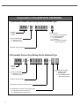
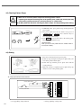
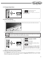
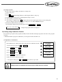
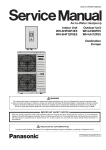
R
User’s
Manual
SPS/C(D)-Bartacking Series
SPS/C(D)-Button Sewing Series
SPS/D -Pattern Tacking Series
Electronically Controlled
Bartacking Machine
(Electronic Control Part)
Electronically Controlled
Button Sewing Machine
(Electronic Control Part)
Electronically Controlled Decorative
Pattern Tacking Machine
(Electronic Control Part)
SUNSTAR MACHINERY CO., LTD.
1) For proper use of the machine,
thoroughly read this manual before use.
2) Keep this manual in a safe place for
future reference in case the machine
breaks down.
MEE-061117
lity
a
u
tQ
Besst Pricevice
Be st Ser
Be
1. Thank you for purchasing our product. Based on the rich expertise and
experience accumulated in industrial sewing machine production, SUNSTAR
will manufacture industrial sewing machines, which deliver more diverse
functions, high performance, powerful operation, enhanced durability, and
more sophisticated design to meet a number of user’s needs.
2. Please read this user’s manual thoroughly before using the machine. Make
sure to properly use the machine to enjoy its full performance.
3. The specifications of the machine are subject to change, aimed to enhance
product performance, without prior notice.
4. This product is designed, manufactured, and sold as an industrial sewing
machine. It should not be used for other than industrial purpose.
R
SUNSTAR MACHINERY CO., LTD.
Organization of the BARTACK S/M MODEL
1) Electronic Presser Foot Rising Device Attached Type
SPS / D - B 1 2 0 1 - H
① Sunstar
Pattern
System
② Series Classification
C : Belt Drive Type
D : Direct Drive Type
④ Material Type
H : For Heavy weight Materials
M : For Medium Materials
L : For Light Materials
K : For Knitted
M(HP) : For Medium Materials
(Hole-fixing device)
③ Bartack Sewing Machine
2) Pneumatic Presser Foot Rising Device Attached Type
SPS / D - B 1 2 0 1 H A ① Sunstar
Pattern
System
② Series Classification
C : Belt Drive Type
D : Direct Drive Type
③ Bartack Sewing Machine
④ Pneumatic Presser Foot Rising System
⑤ Classification of Presser Foot Driving System
20 : Monolithic Driven Presser Foot
22 : Separately Driven Presser Foot
4
⑥ Classification of Option
W : Electronic wiper
attached type
TH : Upper thread holding
device attached type
Organization of the BARTACK S/M MODEL
3) Button Sewing Machine Types
SPS / D - B 1 2 0 2 - 0 1
① Sunstar
Pattern
System
② Series Classification
C : Belt Drive Type
D : Direct Drive Type
④ Button Type
01 : Small-Size Button
(Mechanical Type Wiper)
02 : Large-Size Button
(Mechanical Type Wiper)
03 : Small & Large Size Button
(Solenoid Type Wiper)
③ Button S/M Model Name
4) Pattern Tacking Machine Types
SPS / D - B 1 2 5 4 - H A ① Sunstar
Pattern
System
② Series Classification
D : Direct Drive Type
③ Name of the Pattern Tacking Machine
④ Range of Sewing (X and Y)
·54 : 50×40mm
·63 : 60×3mm
⑥ Classification of Options
TH : The upper thread
Holding device
attached type
⑤ Classification of Usage
HA : Pneumatic clamp raising device for heavy materials
MA : Pneumatic clamp raising device for general use
⑦ Classification of clamp
20 : Unified type clamp
22 : Separated type clamp
5
CONTENTS
1. Machine Safety Regulations -------------------------------------------------------------------- 8
1-1) Machine Transportation -------------------------------------------------------------------------- 8
1-2) Machine Installation ------------------------------------------------------------------------------ 8
1-3) Machine Repair ------------------------------------------------------------------------------------ 8
1-4) Machine Operation -------------------------------------------------------------------------------- 9
1-5) Devices for Safety --------------------------------------------------------------------------------- 9
1-6) Caution Mark Position -------------------------------------------------------------------------- 10
1-7) Contents of Marks ------------------------------------------------------------------------------- 10
2. Electronically Controlled Bartacking SM Specifications -------------------------- 11
3. Preparations before Use ----------------------------------------------------------------------- 12
3-1) Power Connection ------------------------------------------------------------------------------- 12
3-2) Changing Power Voltage ----------------------------------------------------------------------- 13
3-3) Setting Main Shaft Motor Type ---------------------------------------------------------------- 13
3-4) Control Box LED Check ----------------------------------------------------------------------- 14
4. SM Operation 1 (Basic) ------------------------------------------------------------------------- 15
4-1) Names and Functions of Keys in the Operation Box --------------------------------------- 15
4-2) Setting Item Data -------------------------------------------------------------------------------- 16
4-3) Checking Pattern Shape ------------------------------------------------------------------------- 18
4-4) Sewing --------------------------------------------------------------------------------------------- 18
4-5) Changing Sewing Pattern ----------------------------------------------------------------------- 19
4-6) Lower Thread Winding ------------------------------------------------------------------------- 19
4-7) Emergency Stop During Sewing (for B1254) ---------------------------------------------- 19
5. SM Operation 2 (Advanced) ------------------------------------------------------------------- 20
5-1) User Program ------------------------------------------------------------------------------------- 20
5-2) Sewing using Combination Function --------------------------------------------------------- 21
5-3) Sewing using Lower Thread Counter -------------------------------------------------------- 22
5-4) Precautions ---------------------------------------------------------------------------------------- 23
6. Using Memory Switch --------------------------------------------------------------------------- 24
6-1) Memory Switch Operation --------------------------------------------------------------------- 24
6-2) Example of Memory Switch Set-up ----------------------------------------------------------- 24
6
6-3) Memory Switch Functions Table -------------------------------------------------------------- 28
7. Maintaining/Repairing --------------------------------------------------------------------------- 32
7-1) Cleaning C/B ------------------------------------------------------------------------------------- 32
7-2) Replacing Fuse ---------------------------------------------------------------------------------- 32
7-3) Testing the Machine ----------------------------------------------------------------------------- 33
7-4) Other Functions ---------------------------------------------------------------------------------- 37
7-5) Installing and Replacing ROM ---------------------------------------------------------------- 38
7-6) Pattern download from PDA (or PC) -------------------------------------------------------- 43
7-7) Pattern download from CF card --------------------------------------------------------------- 44
7-8) Using the reverse port ----------------------------------------------------------------------------46
8. Error List --------------------------------------------------------------------------------------------- 47
9. How Select the Sewing Pattern List and the Sewing Lange ---------------------- 51
9-1) B1201 Series -------------------------------------------------------------------------------------- 51
9-2) B1202 Series -------------------------------------------------------------------------------------- 52
9-3) B1254 Series -------------------------------------------------------------------------------------- 53
10. BASIC MANUAL --------------------------------------------------------------------------------- 55
7
1
Machine Safety Regulations
Safety instruction on this manual are defined as Danger, Warning and Caution.
If you do not keep the instructions, physical injury on the human body and machine damage might be occurred.
Caution : When the machine is improperly handled, user injury or physical damage to the machine is expected to occur.
Warning : When the machine is improperly handled, critical injury or death of a user is expected to occur.
Danger : When the machine is improperly handled, critical injury or death of a user is expected to occur, and the high-level
of emergency situation would like to happen.
1-1) Machine
Transportation
Danger
1-2) Machine
Installation
Caution
Those in charge of transporting the machine should know the safety regulations very well.
The following indications should be followed when the machine is being transported.
ⓐ More than 2 people must transport the machine.
ⓑ To prevent accidents from occurring during transportation, wipe off the oil on the machine
well.
The machine may not work well or breakdown if installed in certain places. Install the
machine where the following qualifications agree.
ⓐ Remove the package and wrappings starting from the top. Take special notice on the nails
on the wooden boxes.
ⓑ Dust and moisture stains and rusts the machine. Install an airconditioner and clean the
machine regularly.
ⓒ Keep the machine out of the sun. If the machine is exposed in direct ray of light for a long
time, transformation of color and shape can be happened.
ⓓ Leave sufficient space of more than 50cm behind, and on the right, left and back side of
the machine for repairing.
ⓔ Do not operate in explosive atmospheres. To avoid explosion, do not operate this machine in
an explosive atmosphere including a place where large quantities of aerosol spray product
are being used or where oxygen is being administered unless it has been specifically
certified for such operation.
ⓕ The machine were not provided with alocal lighting due to the feature of machine.
Therefore the illumination of the working area must be fulfilled by end user.
[Refer] Details for machine installment are described in 4. Machine Installment.
1-3) Machine Repair
Danger
8
When the machine needs to be repaired, only the assigned troubleshooting engineer educated
at the company should take charge.
ⓐ Before cleaning or repairing the machine, close down the motive power and wait 5
minutes till the machine is completely out of power.
ⓑ Not any of the machine specifications or parts should be changed without consulting the
company. Such changes may make the operation dangerous.
ⓒ Spare parts produced by the company should only be used for replacements.
ⓓ Put all the safety covers back on after the machine has been repaired.
1-4) Machine
Operation
Caution
Bartack Series is made to sew patterns on fabrics and other similar material for
manufacturing. Follow the following indications when operating the machine.
ⓐ Read through this manual carefully and completely before operating the machine.
ⓑ Wear the proper clothes for work.
ⓒ Keep hands or other parts of the body away from the machine operation parts(needle,
shuttle, thread take-up lever, and pulley etc.) when the machine is being operated.
ⓓ Keep the covers and safety plates on the machine during operation.
ⓔ Be sure to connect the earthing conductor.
ⓕ Close down the electric motive power and check if the switch is turned“off”before
opening electric boxes such as the control box.
ⓖ Stop the machine before threading the needle or checking after work.
ⓗ Do not step on the pedal when turning the power on.
ⓘ Do not use several motor per a electric outlet.
ⓙ If possible, install the machine away from loud noise such as high frequency welding
machines
ⓚ Be careful when the upper feed plate comes down to press. Otherwise, the finger or hand
height be hurt at smacking.
Warning
1-5) Devices for
Safety
Caution
1) Make sure that the cover is in place, while the machine is
operating. Otherwise, the belt might injure or cut a finger.
2) Make sure that the power is turned "OFF" before examining
or adjusting the machine.
ⓐ Safety label : It describes cautions during operating the sewing machine.
ⓑ Thread take-up cover : It prevents from any contact between body and take-up lever.
ⓒ Motor cover(D series) : It prevents from accidents during rotation of motor.
Belt cover(C series) : It prevents from accidents during rotation of belt.
ⓓ Label for specification of power : It describes cautions for safety to protect against
electric shock. (Voltage and Hz)
ⓔ Finger guard : It prevent from contacts between a finger and needle.
ⓕ Safety plate : It protects eyes against needle breaks.
ⓒ
ⓑ
ⓐ
ⓕ
ⓔ
ⓓ
9
1-6) Caution Mark
Position
CAUTION
경 고
Caution mark is attached on the machine for safety.
When you operate the machine, observe the directions on the mark.
Position of Warning Mark
Do not operate without finger guard and
safety devices. Before threading, changing
bobbin and needle, cleaning etc. switch off
main switch.
손가락 보호대와 안전장치 없이 작동하지
마십시오.
실, 보빈, 바늘교환시나 청소전에는 반드시 주
전원의 스위치를 꺼 주십시오.
WARNING
경 고
Hazardous voltage will cause injury.
Be sure to wait at least 360 seconds before
opening this cover after turn off main switch
and unplug a power cord.
고압 전류에 의해 감전될 수 있으므로 커버를
열 때는 전원을 내리고 전원 플러그를 뽑고 나
서 360초간 기다린 후 여십시오.
1-7) Contents of
Marks
Caution
1)
CAUTION
경 고
Do not operate without finger guard
and safety devices. Before threading,
changing bobbin and needle, cleaning
etc. switch off main switch.
Warning
손가락 보호대와 안전장치 없이 작동하지 마
십시오.
실, 보빈, 바늘교환시나 청소전에는 반드시
주전원의 스위치를 꺼 주십시오.
2)
WARNING
경 고
Hazardous voltage will cause injury.
Be sure to wait at least 360 seconds
before opening this cover after turn
off main switch and unplug a power
cord.
고압 전류에 의해 감전될 수 있으므로 커버
를 열 때는 전원을 내리고 전원 플러그를 뽑
고 나서 360초간 기다린 후 여십시오.
10
2
Electronically Controlled Bartacking SM Specifications
Model
B1201 H
B1201 M
B1201 L
B1201 K
B1201 HA
Subject Materials
Heavy
General
Light
Knitwear
Pneumatic
Sewing Scope (X,Y)
Maximum Speed
X : 40mm
Max 2,000spm
Max 2,700spm
Stitch Width
Needle
Hook
Presser foot height
Y : 20 mm
Max 2,200spm
0.1 ~ 10 mm
DP×17 #19
DP×5 #16
DP×5 #11
Standard shuttle hook
Max 17 mm
Max 20mm
Thread Trimmer
★
Wiper
★
Lower Thread Counter
★
Memory
P-ROM
Shuttle
Half rotation standard hook
Max Speed Limit
Up to 100 ~ 2,700 spm with an external switch
Needle Bar Stroke
41.2mm
Default Patterns
32 patterns
Maximum Patterns
Maximum 99 patterns (default 32 + 67 additional)
Maximum Stitches
Maximum 10,000 stitches
Scale Scope
20 ~ 200 % (adjustable by 1%)
Motor Specification
550W AC servo motor (standard power: 600 W)
Power consumption
600VA
Drive System
Pulse motor
Optimal Temperature
5°C ˜ 40°C
Optimal Humidity
20% ~ 80%
Optional
0.49Mpa
(5kgf/cm2)
Air Pressure
Power
DP×17 #23
Single-phase : 100~240V, 3-phase : 200~440V, 50/60Hz
11
3
Preparations before Use
3-1) Power Connection
■ Voltage Specification
Voltage information is tagged on the power plug as indicated below.
이 기계의 전기 사양은 공장 출고 시 아래의 V 표기되로 결선되어 있습니다.
The Electric Specification of This Machine is Connected Under V Marked.
V 단상 (1 Phase)
110V V 120V
삼상 (3 Phase)
220V
240V
220V
240V
1. Do NOT use the machine with different voltage specification.
2. Please refer to『Changing Power Voltage』section before changing the voltage.
■ Single phase connection (100V, 110V, 120V, 200V, 220V, 240V)
■ 3-phase connection (200V, 220V, 240V, 380V)
Caution
12
In case of 3-phase 380V, it is necessary to install an additional trans box on the table (check
it out upon making a purchase order).
3-2) Changing Power Voltage
Use SMPS to maintain constant voltage when changing the input voltage.
This machine adopts a free voltage system. Use the voltage connector to set voltage status of the main shaft board at
110V or 220V according to the input voltage.
Incorrect setting of the voltage connector may damage the control box.
Caution
for input
voltage
110V
for input
voltage
220V
3-3) Setting Main Shaft Motor Type
Digital board must be set to dip switch according to the main shaft motor type.
Belt Drive
Type
Direct Drive
Type
13
3-4) Control Box LED Check
LED displays the power supply status to each board. Therefore when problems occurs, it is easy to identify where the
problems were developed.
1. C,D SERIES
14
LED
Power Supply Status
LED
Power Supply Status
LED1
Digital Board +5V Input
LED5
Step Board +24V Input
LED2
Digital Board +12V Input
LED6
Main Shaft Board 220V Input
LED3
Step Board +5V Input
LED7
Main Shaft Board + 5V Input
LED4
Step Board +48V Input
LED8
Main Shaft Board + 12V Input
4
SM Operation 1 (Basic)
4-1) Names and Functions of Keys in the Operation Box
Sewing ready lamp
Ready key
Reset key
LED display
Error lamp
+/Forward
Set pattern No.
–/Back
X-scale
Communication
Y-scale
Serial download (Note 1)
Speed
Production counter
CF card download (Note 1)
Lower thread winding
Register
Select
(Note 1) : To use the
download function, the
‘Communication Ready’
key should be pressed at
the same time.
※ Previous pattern number will appear when you turn on the power.
Refer to the following functions of LED and keys.
Press READY to prepare the machine for sewing. READY light will turn on.
Indicates an error.
Press to select item. At every press item changes as below. Selected item will be lighted.
Pattern
No.
X Scale %
Y Scale %
Sewing
Speed
Counter
Thread
winding
15
Press to set the machine back to the default value.
Press to increase/decrease the set value or to move the needle bar backward or forward.
One click to call a certain pattern.
Caution
”
1) For direct connection type, if the head is laid down on the side while the power is on,“ oPEn”
will appear. If READY key is on at this time, sewing does not start with your pedaling.
”will not appear until sewing is
2) If the head is laid down on the side while sewing,“ oPEn”
completed.
4-2) Setting Item Data
You can set each item in the following order.
Pattern No.
X Scale %
Y Scale %
Sewing Speed
A. Turn on the power.
Item “Pattern No.” will lit up and the previous pattern number will appear.
B. Set the pattern number.
1) Press SELECT to display NO.
2) Press +/FORWARD , –/BACK to display “2” on the
screen (setting pattern No.2).
※ Refer to the program list.
C. Set X Scale %.
1) Press SELECT to display item “X-Scale”.
2) Press +/FORWARD , –/BACK to set within the range
of 20%~200%.
16
D. Set Y Scale %
1) Press SELECT to display item “Y-Scale”.
2) Press +/FORWARD , –/BACK to set within the range
of 20%~200%.
E. Set Sewing Speed
1) Press SELECT to display item “Speed”.
2) Press +/FORWARD , –/BACK to set the speed at 1700.
F. Setting Done
1) Press READY .
2) Presser plate will move/lift and READY light will be on.
The machine will be on standby
※ You can press SELECT to confirm the setting.
Caution
Check the pattern number before starting the machine.
1) If READY is pressed with the pattern number “0” (default status), the machine will move
back to original point. Use it to check the machine original point.
2) If you select a pattern that contains no data, error “Er01” will appear. Select other pattern.
H. Threading (for B1254)
Press EMERGENCY STOP switch in the READY status. Upper feed plate and presser foot will descend.
Press EMERGENCY STOP switch again to lift the upper feed plate and presser foot.
17
4-3) Checking Pattern Shape
Caution
1) Make sure to check the pattern shape after selecting pattern number.
1) If pattern goes beyond the driving limit of the presser plate, needle and presser plate may
conflict during sewing and result in serious problems, i.e. needle break.
2) Do NOT pedal 2nd step while checking the pattern shape. 2nd step pedaling starts sewing.
1st Step
2nd Step
1) In READY status, press pedal 1st step to bring down the
presser plate.
2) The presser plate moves by one stitch at every press of
+/FORWARD or –/BACK . Press down the keys to
move the plate continuously.
3) Press RESET to move the needle to the starting point.
The presser plate will move up.
◀ CAUTION ▶
Take your foot off the pedal when the needle starts to
move (even a stitch).
4-4) Sewing
1) Place the work material on the presser plate.
2) Pedal 1st step to bring down the presser plate. Take your
foot off the pedal to lift the plate.
3) Pedal 2nd step with the presser plate down and the
sewing will start.
4) When the sewing is completed, presser plate will go up
and move to the sewing starting point.
■ 2-step pedal switch interconnection
1st step pedal switch
2nd step pedal switch
1st step pedaling: clamp function
18
2nd step pedaling: sewing starts
4-5) Changing Sewing Pattern
1) Press READY (READY light will turn off).
2) Press SELECT to display item “NO”.
3) Set (B) ~ (F) items in 4-2 and move to the item of
checking pattern shape.
4-6) Lower Thread Winding
A. Lower thread winding while sewing
Thread as shown in the picture and wind the lower thread.
B. Lower thread winding only
Caution
During lower thread winding, the feed plate does not move but the needle moves. Therefore,
make sure no object is under the needle during the winding.
1) Press SELECT to select the item “WINDER” .
※ If READY is on, WINDER is not selected.
2) Press READY .
3) Press the pedal switch to 2nd step.
Bobbin winder will start to wind.
4) Press the pedal switch to 2nd step again. Winding will stop.
5) Press READY to end winding.
◀ CAUTION ▶
When using hole fixing device, if you shift to bobbin
winding mode and pres READY, the pin hole will go
down and the presser plate will move to the original
point.
4-7) Emergency Stop During Sewing (for B1254)
Pressing EMERGENCY STOP during sewing will stop at present position. Press FORWARD/BACK to move the feed plate
stitch by stitch. If you want to stop the sewing work altogether, press EMERGENCY STOP again. If you want to re-start the
sewing at the stopped position, press the pedal again.
19
5
SM Operation 2 (Advanced)
5-1) User Program
You can register and use 26 different programs (P1-P26) as user programs.
The 26 user programs can hold information, i.e. pattern number, X scale %, Y scale %, and sewing speed.
It will be convenient for you to register repeatedly used patterns in the user program.
(1) Registering the User Program
Ex) Registering the following set-up as P1.
Pattern Number 3
X scale %: 50%
Y scale %: 80%
Maximum speed limit: 1800spm
P–––
P 0 1–
3
A. Press SELECT and turn on the power.
B. Press P1 .
C. Press SELECT to display number items
Press +/FORWARD , –/BACK to set the pattern number at 3.
D. Press SELECT and use +/FORWARD , –/BACK to set the X scale %
at “50%” and Y scale % at “80%” and the maximum speed limit at “1800
spm”.
50
80
1800
P–––
E. Press READY to end registration.
※ To register P2-P26, press P2-P26 in B of the above and follow the rest
of the procedures.
F. After registration, turn off the power and turn it on again.
(2) Selecting the User Program
Reg.
No.
20
Key(s)
Reg.
No.
Key(s)
Reg.
No.
Key(s)
Reg.
No.
Key(s)
P01
P1
P08
P1 + P3
P15
P2 + P6
P22
P1 + P2 + P3
P02
P2
P09
P1 + P4
P16
P3 + P4
P23
P1 + P2 + P4
P03
P3
P10
P1 + P5
P17
P3 + P5
P24
P1 + P2 + P5
P04
P4
P11
P1 + P6
P18
P3 + P6
P25
P1 + P2 + P6
P05
P5
P12
P2 + P3
P19
P4 + P5
P26
P4 + P5 + P6
P06
P6
P13
P2 + P4
P20
P4 + P6
P07
P1 + P2
P14
P2 + P5
P21
P5 + P6
Caution
By default, P1-P26 contain information of pattern number 1, X & Y scale 100%, and speed 1500.
To not display P1-P26 mark when scrolling the pattern numbers, set the pattern number “0” in
C of the above procedures.
(3) Sewing Operation
Ex) Do sewing work according to P1 and then according to P3.
A. Turn on the power.
B. Press P1 .
C. Press READY . READY lamp will turn on and feed plate will move and go up.
D. Check the pattern shape (refer to <Checking Pattern Shape> section).
E. After checking, you can start sewing.
F. After sewing is completed, press P3 . Feed plate will search the original point and move to the starting point.
(You can change the pattern with a short key (single press) even with the READY lamp on).
G. Perform D and E of the above procedures.
※ P1-P26 will be displayed when changing pattern using +/FORWARD or –/BACK .
0 to 99 ↔ P1 to P26
Unregistered programs will not be displayed.
5-2) Sewing using Combination Function
You can list the pre-registered user programs (P1-P26) in Cnb1 and Cnb2 and change the pattern in the order of the programs
on the list.
※ Maximum number of program combinations you can register in Cnb1 and Cnb2 is 30.
(1) Registration of Combinations
Ex) Combine P1, P2, and P3 (in that order) and register the combination in Cnb1.
A. Turn on the power pressing P1 and SELECT .
B. Press SELECT and then P1 .
C. Press SELECT and then P2 .
D. Press SELECT and then P3 .
E. Press READY to complete the registration.
Cnb1
01.01
02.02
03.03
Cnb1
F. Turn off the power and turn it on again.
※ To register in Cnb2, press P2 and SELECT in A of the above procedure.
Patterns that are not registered with function keys (P1-P26) cannot be combined.
Caution
21
(2) Sewing Operation
A. Turn on the power.
B. Change the pattern number using +/FORWARD or –/BACK . At every press, the pattern number will change as
shown below. Scroll down to change.
0 to 99 ↔ P1 to P26
※ Unregistered P1-P26 and Cnb1-Cnb2 are not displayed.
C. Press READY . READY lamp will be lit and feed plate will move and go up.
D. Check the pattern shape and start sewing.
E. Sewing stages are formed according to the combination. Sewing will return to the first stage after each cycle is
completed. Sewing will be done repeatedly.
※ ① If you want to go to the previous or the next pattern, press +/FORWARD or –/BACK while READY lamp is on.
Number will be changed and the feed plate will move to the starting point.
※ ② P1-P26 in Cnb1-Cnb2 will change if patterns in P1-P26 have been changed after registration in Cnb1-Cnb2.
※ ③ Make sure to check each pattern shape (refer to『Checking Pattern Shape』section).
※ ④ The machine will automatically shift to the next pattern within the combination (for example Cnb1).
Caution
If you undo READY and press RESET during the combination sewing, you will move to the
initial state of the selected combination.
5-3) Sewing using Lower Thread Counter
Workload counter can also be used as a lower thread counter. If you are repeating the same pattern, the machine will stop
when it reaches the sewing limit of one bobbin. At this time, the lower thread counter should be set at reduction mode.
Caution
A.
B.
C.
D.
E.
F.
G.
22
The counter is set as a workload counter (addition mode) as default.
To set the counter as a lower thread counter, you need to change the memory switch (refer
』).
to『 Using Memory Switch』
Press SELECT with the READY light off. “COUNTER” will be displayed.
Press RESET .
Set the sewing limit of a single bobbin, using +/FORWARD and –/BACK .
The counter value will drop by 1 after each sewing is completed.
When you sewed to the set limit, the machine will not sew even you pedal.
Replace the bobbin and press RESET .
Repeat (D) ~ (F).
5-4) Precautions
A. Make sure to thread and sew after the thread tension plate is shut. The plate opens after trimming.
B. If error lamp turns on, investigate the cause and take appropriate actions.
C. Do not pull the sewing fabric, while sewing is conducted. The needle position might be improperly changed.
In the case of needle position distortion, press READY twice to bring the needle to the right position.
D. Do NOT turn off the power with the needle bar down.
■ Sewing speed for different work
Sewing speed (SPM)
C/D-Series
Denim 8 sheets
2,200 ~ 2,700
Denim 12 sheets
2,200 ~ 2,500
Clothes
2,200 ~ 2,700
Clothes (artificial thread)
2,000 ~ 2,300
Knit
1,800 ~ 2,000
Underwear
1,800 ~ 2,000
E. Set the sewing speed according to the above table in order to prevent thread break from heat.
F. For materials like underwear, lower the needle bar height in order to prevent jump stitch (refer to <Adjusting Needle Bar
Height>).
23
6
Using Memory Switch
6-1) Memory Switch Operation
The memory switch has two major functions: general sewing function (changing general operation) and servo motor
controlling function (changing servo motor operation).
1) Turn on the power pressing READY and RESET .
2) For changing general sewing-related functions, press A .
3) For changing servo motor control-related functions,
press B and operate the memory switch.
※ Turn off the power and back on again after changing the
memory switch set-up.
6-2) Example of Memory Switch Set-up
(1) Setting maximum sewing speed
A Turn on the memory switch and press +/FORWARD . You will
see “A-01” on the screen.
B. Press READY and you will see the present set-up.
2000
C. Press –/BACK to change the set-up value to 1800.
1800
D. Register the set-up value by pressing READY .
24
A-01
A-01
(2) Setting Softstart Speed
You can change the speed for the first 1-5 stitches by 100 spm.
Scope
Default
1st stitch
400 ~ 900
400 spm
2nd stitch
400 ~ 2700
900 spm
3rd stitch
400 ~ 2700
2,300 spm
4th stitch
400 ~ 2700
2,300 spm
5th stitch
400 ~ 2700
2,300 spm
The above values may not be the same for all machine types. (above is for M and H types)
Caution
For the maximum rotation number, general sewing function No. A-01 (maximum sewing
speed) applies first.
Ex) Changing the 1st stitch 400→900 rpm and the 2nd stitch 900→1,200 rpm
A. Turn on the memory switch and press +/FORWARD to display
“A-02” on the screen.
A-02
B. Press READY to display the present set-up value (1st stitch speed:
400 spm).
1-04
C. Press +/FORWARD to change to “1-09” (changing to 900 spm).
1-09
D. Press SELECT (2nd stitch speed 900spm is displayed).
2-09
E. Press +/FORWARD to change to “2-12” (changing to 1,200 spm)
2-12
F. Register the set-up using READY .
A-02
25
(3) Setting Pattern Data Call Function
You can inactivate calling unnecessary patterns. This prevents calling wrong patterns by mistake and helps you call the
necessary patterns.
Ex) Inactivating calling of patterns 1 and 2
A. Turn on the memory switch and press +/FORWARD to display
“A-03” on the screen.
A-03
01-1
B. Press READY to display the present set-up value.
ⓐ part : pattern number
ⓑ part : 0 :calling impossible
ⓑ part : 1 :calling possible
ⓐ
C. Press –/BACK to change “1” in ⓑ to “0”.
01-0
D. Press SELECT to change “1” in ⓐ to “2”
02-1
E. Press –/BACK to change “1” in ⓑ to “0”.
02-0
F. Register the set-up using READY .
ⓑ
A-03
(4) Setting the Counter Function
Ex) Changing production counter (addition mode) to lower thread counter (reduction mode)
A. Turn on the memory switch and press +/FORWARD to display
“A-05” on the screen.
ⓐ
B. Press READY to display the present set-up value.
0
C. Press +/FORWARD to set “05-1”.
ⓐ part : 0 : production counter
ⓐ part : 1 : lower thread counter
1
D. Register the set-up using READY .
26
A-05
A-05
(5) Selecting Upper Thread Holding Function
For pneumatic type, if you want to use an upper thread holding function, change the parameter as below.
A. Turn on the memory switch and press +/FORWARD to display
“A-32” on the screen.
A-32
ⓐ
B. Press READY to display the present set-up value.
ⓐ part : 0 : holding device OFF
ⓐ part : 1 : holding device ON
0
C. Press +/FORWARD to change ⓐ “0” to “1”
1
D. Register the set-up using READY .
A-32
(6) Selecting between Integrated/Separated Pedals
For pneumatic type, if you want to use a separated pedal, change the parameter as below.
Ex) Using a separated pedal
A. Turn on the memory switch and press +/FORWARD to display
“A-33” on the screen.
B. Press READY to display the present set-up value.
ⓐ part : 0 : integrated pedal
ⓐ part : 1 : separated pedal
C. Press +/FORWARD to change ⓐ “0” to “1”.
D. Register the set-up using READY .
Caution
A-33
ⓐ
0
1
A-33
To use a separated pedal as an integrated pedal, press -/BACK between step B and step C
and change ⓐ “1” to “0.” Then register the change using READY .
27
6-3) Memory Switch Functions Table
(1) General sewing functions (A Group)
Turn on the power pressing
No.
Setting maximum sewing speed
A-02
Setting speed for the first 1-5 stitches
(Softstart function, different by type)
A-04
A-05
A-06
A-07
A-08
Scope
General:
100 ~ 2,700
Heavy:
100 ~ 2,700
Light:
100 ~ 2,000
Knitwear:
100 ~ 2,000
For Pneumatic Purpose: 100 ~ 2,200
Buttons:
100 ~ 2,500
Pattern taker: 100 ~ 2,500
1st stitch: 400~900
2nd stitch: 400~2,000
3rd stitch: 400~2,000
4th stitch: 400~2,000
5th stitch: 400~2,000
2,300 spm
2,300 spm
1,800 spm
1,800 spm
1,800 spm
2,300 spm
2,200 spm
400 spm
900 spm
2,300 spm
2,300 spm
2,300 spm
1202
1201
1~22 : 1
1~33 : 1
23~99 : 0 34~99 : 0
0 : calling impossible
1 : calling possible
Setting display and change possibility of X,Y scale
rate and maximum speed limit (prevent errors or mistakes)
Setting counter function
Production counter : addition count
Lower thread counter : reduction count
0 : change impossible
1 : change possible
1
0 : production counter
1 : lower thread counter
0
Setting center point for scale
Setting whether to search original point after sewing
(sewing with ordinary pattern number)
Setting whether to search original point after sewing
(sewing with function combination)
Setting drive scope to infinite
A-10
A-11
A-12
A-13
Setting starting angel for X, Y drive
Setting trimming speed
Setting reverse rotation after trimming
Setting angle for reverse rotation after trimming
0 : original point
1 : sewing start point
0 : OFF
1 : ON
0 : OFF
1 : ON
0 : Infinite
1 : limited
–100 ~ 100°
200 ~ 400spm
0 : OFF, 1 : ON
0~70°
0 : OFF
1 : ON
0 : OFF, 1 : ON
0 : OFF
1 : ON
0~1000
4~1024 ms
0 : trim ON
1 : trim OFF
4~72 ms
4~1020 ms
4~1020 ms
4~1020 ms
10~25%
10~25%
10~25%
10~25%
A-14
Setting whether to use electronic wiper
A-15
A-17
A-18
Faster moving of presser foot after trimming
Setting search for original point after certain amount of sewing
(after amount set in A-17)
Number of automatic search for original point
Time for electronic wiper ON
A-19
Canceling trimming
A-20
A-21
A-22
A-23
A-24
A-25
A-26
A-27
A-28
A-29
Time for solenoid 0 full on (clamp solenoid)
Time for solenoid 1 full on (trimming solenoid)
Time for solenoid 2 full on (sub solenoid 2)
Time for solenoid 3 full on (sub solenoid 3)
Solenoid 0 duty (clamp solenoid)
Solenoid 1 duty (trimming solenoid)
Solenoid 2 duty (sub solenoid 2)
Solenoid 3 duty (sub solenoid 3)
Delay time for clamp solenoid moving up
Delay time for clamp solenoid moving down
A-30
Setting OFF time for electronic wiper
4~1020 ms
A-31
A-32
Setting whether clamp moves up/down after mid trimming
Setting pneumatic thread holder
Setting integrated/separated pedal
(For pneumatic only. Others have integrated pedals)
0 : Down, 1 : Up
0 : OFF, 1 : ON
0 : integrated
1 : separated
0 : OFF
1 : ON
A-33
Default
Setting pattern data calling
(You can set for each pattern)
A-09
A-16
28
. Turn on the memory switch pressing P1 .
Functions and Description
A-01
A-03
and
4~1020 ms
A-34
Setting whether to use pin hole device
A-35
Setting whether to use head open/close
0 : OFF
1 : ON
A-36
Whether to use upper stop when turn power on
0 : OFF
1 : ON
A-37
Set time for AC off checking
4 ~ 48 [ms]
A-38
Set time for voltage overload checking
4 ~ 1024 [ms]
Unit
100spm
100spm
1254
1~56 : 1
57~99 : 0
0
0
0
1
Belt type : –24°, Direct : –24°
400 spm
0
0°
1254
1201, 1202
0
1
1
1°
100spm
1°
0
1000
100 ms
4
4 ms
0
52 ms
100 ms
100 ms
100 ms
10%
20%
20%
20%
Pneumatic
100 ms
Others
40 ms
Others
500 ms
Hole fix device
100 ms
1
0
0
Hole fix device
Others
0
1
Only in Direct type
1
Only in Direct type
1
20 ms
20 ms
4 ms
4 ms
4 ms
4 ms
1%
5%
5%
5%
4 ms
4 ms
(2) General sewing functions (C Group)
Turn on the power pressing
and
. Turn on the memory switch pressing P3 .
[BS1201, B1202 Series]
No.
Functions and Description
Scope
Default
Unit
C-01
When the electronic wiper is used (A15=1), set the standby time
from trimming to wiper operation.
1 255[ms]
165[ms]
1[ms]
Scope
Default
Unit
0[us]
[BS1201, B1202 Series]
No.
Functions and Description
C-01
X-step motor driving time adjustment
0 255[us]
C-02
Y-step motor driving time adjustment
0 255[us]
0[us]
C-03
Heat cut operation time setting
120 500[us]
300[ms]
29
(3) Servo Motor Control Functions (B Group)
Turn on the power pressing
and
. Turn on the memory switch pressing P2 .
Default
No.
Function Name
Functions and Descriptions
Scope
Unit / Reference
Fortuna III Forturn IV
30
Sanyo
B-01
Speed for location detection for stop
pos_spd
2~510
220
400
400
2spt
B-02
Speed immediately before stop
end spd2
0~255
16
50
50
1spt
B-03
Delay time to stop at right position
StopDelay
4~1020
80
20
20
4ms
B-04
First distance of location detection
DIST1
0~255
50
50
50
1Pulse
B-05
Speed P-Gain
KC1A
0~1000
20
15
30
1
B-06
Not used
–
B-07
Speed D-Gain
KC1C
B-08
Not used
–
B-09
Position P-Gain
KF1A
B-10
Not used
–
B-11
Position D-Gain
KF1C
0~5000
B-12
Speed unit
spd_unit
1~255
100rpm
1rpm
B-13
Strength when pully fix
KH1
10~100
40
1
B-14
Distance recovered when pully fix
KH2
10~1000
20
1
B-15
Speed reduction rate from stop sign to
location detection speed
accelA
2~100
60
40
35
2
B-16
Speed increase rate
accelB
10~100
70
70
25
1
B-17
Speed reduction rate
accelC
10~100
30
40
15
1
B-18
Speed reduction rate from location detection
speed to stop
accelD
2~100
6
8
5
1
B-19
Sewing machine inertia value
Inertia
0~255
0
Inertia tuning
B-20
Not used
SPMUPPER
–
–
–
B-21
Highest stop position of UDC
UPPosition
0~8000
B-22
Not used
IND_REFM
–
B-23
Second P-Gain
KF2A
0~1000
350
500
200
1
B-24
Second D-Gain
KF2C
0~5000
2500
3000
500
1
B-25
SM PULLY SIZE
PULY_SIZEM
0~8000
1140
1440
8000
1
B-26
Lowest stop position
CutStartM
0~358
B-27
Upper stop position
CutEndM
0~358
B-28
Synchro sensor detection time
SLockTmM
5~1275
40×0.1
0.5s
B-29
Overload detection time
OvLoadM
5~1275
30×0.1
0.5s
B-30
Motor fixing is possible/impossible,
while the machine is not in operation
HOLD_FG
0: impossible
1: possible
0: impossible
1
B-31
Direction of servo motor rotation
DIR_MODE
0: anti-clock
1: clockwise
1: clockwise
1
B-32
Original point sensor detection time
Orgtm
4~1020ms
500ms
4ms
0~1000
0
15
0
175
125
150
1500
440
1750
720
700
4000
1
1
70
0
1
–
–
800
1
–
–
–
1
–
–
–
0~1000
–
–
–
0
Fortuna III is a
fixed value
※ Shaded Areas
Stop order
Sudden section by pedal slowdown
Speed
Pos_spd
DIST1
24°(DIST2)
Up, Down Edge
■ B-04 (DIST1): A location where sudden speed reduction takes place for stop. The higher this value, the more stable
speed reduction, but final stop distance will be longer.
■ B-08 (KC2): Can be calculated by inertia tuning. The higher this value, the slower the distance tracking. (FOR
PROFESSIONAL ENGINEERS ONLY)
■ B-12 (KF2): Can be calculated by inertia tuning. The higher this value, the slower the speed tracking. (FOR
PROFESSIONAL ENGINEERS ONLY)
■ B-15 (accelA): Can be calculated by inertia tuning. This represents speed reduction from after pedal stop signal input
to sudden stop. The higher value means sudden slowdown, but too high value may result in inability to
sudden slowdown.
■ B-17 (accelB): Represents level of speed acceleration by pedal. The higher this value, the higher acceleration to the
target speed, but speed fluctuation may also increase when reaching the target speed.
■ B-18 (accelC): Represents level of speed reduction by pedal. The higher this value, the faster reduction of speed to the
target speed, but speed fluctuation may also increase when reaching the target speed.
※ Examples of the shaded functions
① Unable to come to sudden stop and stops at one more stitch
– This happens when the machine has been operating at a very high speed or when the workload is large and the
machine cannot reduce speed in short time. Increase B-04 and B-15 values to an appropriate level.
② Motor is slow to adjust to new speed when machine speed is changed
– This happens when the speed change level is smaller than the machine workload change. Increase B-17 and B-18
values to an appropriate level.
31
7
Maintaining/Repairing
7-1) Cleaning C/B
Caution
Turn off the power before cleaning the machine to prevent accidents associated with
mistaken machine operation.
Clean the cooling fan and the inside of the control box on a
weekly basis.
[Inside C/B]
[C/B Rack Structure]
No.
Board type
1
Power board
2
Digital board
3
Step board
4
Main shaft board
7-2) Replacing Fuse
Caution
■ To prevent electric shock, wait 5 minutes after power off to open the cover.
■ Make sure to turn the power off when opening the control box. Change to a fuse of a
designated capacity.
1 fuses are required.
32
No.
Capacity
Use
F1
15A
Main power protection
7-3) Testing the Machine
Test each part of the machine. If malfunction is found, address the relevant electrical errors.
※ To use the machine test function after running the machine test, press SELECT and then move by using +/FORWARD
and –/BACK . To completely stop the machine test and then start sewing, turn off the power and turn it back on again.
(1) Running Machine Test
P1
P2
1. Turn on the power using P1 , P2 , and P3 simultaneously.
2. TEST sign will briefly appear on the screen and you will
then see “t-01”.
P3
(2) Testing Step Motor Drive and Original Point Sensor
Up
Clamp Up
Needle
Left
Right
Down
Caution
Clamp Down
1. Turn on the Machine Test and press READY .
2. Press the relevant key and the needle will move.
3. X-axis original sensor signal and Y-axis original sensor
signal will appear on X-scale lamp and Y-scale lamp,
respectively.
4. You will know it is OK if the above two lamps are on
when the needle is on the left upper side of the feed
plate.
5. Since the clamp shaft does not use the sensor, the normal
operation can be checked with the up/down movement.
6. End the test by pressing SELECT .
During the test, make sure that the feed plate does not feed the power to the limit. This may
cause problem in power supply.
33
(3) Solenoid Test
1. Run the Machine TEST and then press +/FORWARD
and –/BACK to display “t-02” .
2. Press READY .
3. Press the relevant key to run the solenoid and the
relevant lamp will turn on.
4. Press SELECT to end the test.
※ Wiper solenoid is an optional function for pneumatic
specification (HA).
※ For 1254 (pattern taker), RESET button will serve as a
presser foot solenoid and the key will activates upper
feed plate in pneumatic type.
Thread Trim Solenoid
Work Clamp Solenoid
Aux2 Solenoid
Aux3 Solenoid
(4) Testing Main Shaft Motor
Main Motor Run/Stop
Increase the speed
Motor Speed
Decrease the speed
1. Run the Machine TEST and then press +/FORWARD
and –/BACK to display “t-03” .
2. Press READY .
3. Press READY and the motor will rotate. Speed of the
main shaft motor will be displayed on the screen. Press
READY again to stop.
4. Adjust the speed using +/FORWARD and –/BACK
keys.
5. Press SELECT to end the test.
(5) Testing Encoder
1. Run the Machine TEST and then press +/FORWARD
and –/BACK to display “t-04” .
2. Press READY .
3. Rotate the pulley clockwise and the screen will display
encoder angle. No lamp will turn on.
Encoder Angle
◀ CAUTION ▶
No change in value means encoder-related errors
including connector.
4. Press SELECT to end the test.
34
(6) Testing Synchronizer
No. of circulation
1. Run the Machine TEST and then press +/FORWARD
and –/BACK to display “t-05” .
2. Press READY .
3. Rotate the pulley manually. The screen will display the
rotation number and the No. lamp will display synchro
signal.
◀ CAUTION ▶
No change in value after more than one rotation
means synchro-related errors including connector.
4. Press SELECT to end the test.
(7) Testing Pedal Input
1st Step
2nd Step
Aux1 switch
Aux2 switch
1. Run the Machine TEST and then press +/FORWARD
and –/BACK to display “t-06” .
2. Press READY .
3. Press pedal to 1st step and No. lamp will turn on. Press
to 2nd step and you will see X-scale lamp be lit.
Pressing Aux 1 switch will turn on Y-scale lamp and
Aux 2 switch on speed lamp.
4. Press SELECT to end the test.
(8) Testing Auxiliary Output
Aux. output On/Off
End of test
1. Run the Machine TEST and then press +/FORWARD
and –/BACK to display “t-07” .
2. Press READY .
3. Press READY to light on all of the 8 auxiliary output
(J11 on digital circuit board). Press READY again to
turn off all of them.
4. Press SELECT to end the test.
35
(9) Testing Auxiliary Input
1. Run the Machine TEST and then press +/FORWARD
and –/BACK to display “t-08.”
2. Press READY .
3. Relevant lamps will be turned on according to the 8
auxiliary input signals (J9 on the digital circuit board).
4. Press SELECT to end the test.
Aux8 input
Aux7 input
Aux6 input
Aux5 input
Aux4 input
◀ CAUTION ▶
Inputting air pressure reduction only applies to
pneumatic type.
Aux3 input
Aux2 input
Inputting the
external convering
of function key
(10) Testing Clamp Solenoid Operation
1. Run the Machine TEST and then press +/FORWARD
and –/BACK to display “t-09” .
2. Press READY .
3. Press SELECT to set the delay times for clamp moving
up and down. Use +/FORWARD and –/BACK keys
to change the delay time.
4. Press RESET to end the test.
Delay setup when the clamp
ascends
Delay setup when the clamp
descends
Press pedal
36
7-4) Other Functions
(1) Initializing Memory Switch
You can initialize the memory switch back to the default condition.
1) Turn on the power pressing +/FORWARD and –/BACK
at the same time.
2) Memory switch will be initialized with the screen like
below.
3) You will soon see the initial screen.
◀ CAUTION ▶
Memory switch initialization will remove all of your
memory switch set-ups.
(2) Inertia Tuning
The controller performs an automatic inertia tuning suitable to the machine load.
Do not perform this function unless tracking of the sewing speed is too slow or the machine stops at one stitch later.
1) Press READY and –/BACK at the same time to turn the
power on.
2) The following screen appears.
3) Press the foot pedal until it moves to Step 2. The inertia
tuning is automatically conducted.
◀ CAUTION ▶
After inertia tuning, the needle bar is stopped at a
random position. Therefore, place the needle bar at
the origin position, and turn off the power. Soon
after, turn on the power again.
(3) Formatting Scalable Memory
You can turn the memory (where you downloaded patterns) to the default status.
P3
1) Turn on the power pressing –/BACK and P3 at the
same time.
2) Memory will be formatted with the screen like below.
◀ CAUTION ▶
All of your downloaded patterns will be erased.
37
(4) Checking Program Version
1) The following screen will appear for around 0.5 seconds after turning on the
power. bH represents machine model and 16 its version.
Item
Classification
Presser
Pneumatic Pneumatic
foot
Maximum speed [spm]
use
error
error
Version display
Upgrade version dispaly
Belt
Direct
Belt
Direct
2,200
bA16
dA16
9A20
FA20
B1201HA
Pneumatic
B1201H
Heavy
×
×
2,700
bH16
dH16
9H20
FH20
B1201M
Ordinary
×
×
2,700
bN16
dN16
9N20
FN20
×
B1201MHP Hole fixing device
×
×
2,700
bP16
dP16
9P20
FP20
B1201L
Light
×
×
2,000
bL16
dL16
9L20
FL20
B1201K
Knitwear
×
×
2,000
bh16
dh16
9h20
Fh20
B1202
Buttoning
×
×
2,500
bb16
db16
9b20
Fb20
For (regular) pneumatic purpose
2,500
×
PA04
×
SA20
For heat cut
2,200
×
×
×
SC20
For full rotation
2,500
×
×
×
Sr20
For (regular) pneumatic purpose
2,500
×
EA02
×
UR20
For heat cut
2,200
×
×
×
UC20
For full rotation
2,500
×
×
×
Ur20
B1254
B1263
[Differences in programs and functions by type]
Caution
SPS/C(D)-B12XX series automatically recognizes the main shaft type, and based on the
recognition, either the program for direct drive type or belt-type is displayed on the screen.
7-5) Installing and Replacing ROM
(1) ROM Types and Classification
① Scalable pattern ROM : This ROM contains sewing patterns made according to user’s request and is not installed as a
default. It is issued and installed for use at every request from the user.
Scalable pattern ROM
38
Sticker
■ Sticker : Usually 8 digits, but may be different according
to design.
Ex) bc000928, bj000930 ...
② Program ROM : This ROM contains essential programs for operating the sewing machine and is installed as a default.
But it should be replaced or updated for adding or changing functions.
■ Sticker : 4-digits.
Ex) b005, b006, b□07...
PROGRAM-ROM
Sticker
Name
Display on digital
board
Type
A/B
ROM type
Belt
Direct
General
U9
U18
27C256
Scalable pattern ROM
PDA
No. of pins
General
28
AT28C010
C/D
×
U8
U8
A/B
U20
32
×
27C512
Program ROM
28
28
27C512
C/D
×
U7
PDA
×
<ROM Type and Installation Location >
(2) Location of ROM Installation and Precautions
Caution
1) Make sure the power is OFF and the screen is blank before installing/replacing ROM.
2) Wrong mark of direction may damage ROM.
3) Make sure the pin is installed accurately on the socket.
4) When removing the existing ROM, be careful not to damage the board by using IC
removing device or small (–) shape screw.
< Loosen two screws
for fixing the front
cover of the control
box and disassemble
the digital board by
pulling its handle.>
Direction Marking
Must Mount that the
direction marking
comes to the left
Program ROM
Pattern stored
ROM Position
<Position of Rom on the digital board
and exchanging>
Location of ROM installation
39
(3) Using Scalable Pattern ROM
① Installing Scalable Pattern ROM
1) Take the cover off the Bartack control box.
2) As shown in the previous page, install the scalable design ROM onto the “U9” location on the digital board. Make
sure to align the direction with the indication on the board (so the direction mark is on the left). Pin should go into
the socket accurately.
② Using Scalable Pattern
Caution
1) If the pattern number is set up by default as call impossible, change the set-up of the
pattern to call possible.
2) Check the pattern shape and confirm that the needle and the presser plate do not conflict.
(for B1201 series)
Ex) Changing the scalable pattern No.33 and No.34 to call possible
A. Turn on the power, pressing READY and RESET at the same time.
Press A and then +/FORWARD to display “A-03” on the screen.
B. Press READY to display the present set-up value.
ⓐ part : pattern number, ⓑ part : 0 : call impossible, 1 : call possible
A-03
01-1
ⓐ
ⓑ
C. Press SELECT to change ⓐ “1” to “33”.
D. Press +/FORWARD to change ⓑ “0” to “1”.
E. Press SELECT to change ⓐ “33” to “34”.
F. Press +/FORWARD to change ⓑ “0” to “1”.
G. Press READY to register.
H. Turn off the power and back on again. Select your desired number.
40
33-0
33-1
34-0
34-1
A-03
(For B1202 series)
Ex) Changing scalable pattern No.34 and No.35 to call possible.
A. Turn on the power, pressing READY and RESET at the same
time. Press A and then +/FORWARD to display “A-03” on the
screen.
B. Press READY to display the present set-up value.
ⓐ part : pattern number, ⓑ part : 0 : call impossible, 1 : call possible
A-03
01-1
ⓐ
ⓑ
C. Press SELECT to change ⓐ “1” to “34”.
34-0
D. Press +/FORWARD to change ⓑ “0” to “1”.
34-1
E. Press SELECT to change ⓐ “34” to “35”.
35-0
F. Press +/FORWARD to change ⓑ “0” to “1”.
35-1
G. Press READY to register.
A-03
H. Turn off the power and back on again. Select your desired number.
(For B(BR)1254 series)
Ex) Changing scalable pattern No.57 and No.58 to call possible
A. Turn on the power, pressing READY and RESET at the same time.
Press A and then +/FORWARD to display “A-03” on the screen.
B. Press READY to display the present set-up value.
ⓐ part : pattern number, ⓑ part: 0 : call impossible, 1 : call possible
A-03
01-1
ⓐ
ⓑ
C. Press SELECT to change ⓐ “1” to “57”.
D. Press +/FORWARD to change ⓑ “0” to “1”.
E. Press SELECT to change ⓐ “57” to “58”.
F. Press +/FORWARD to change ⓑ “0” to “1”.
G. Press READY to register.
H. Turn off the power and back on again. Select your desired number
57-0
57-1
58-0
58-1
A-03
41
(4) Using Hole Fixing Device
■ SUB machine type
Belt type: SPS/C-B1201M(HP)
Direct connection type: SPS/D-B1201M(HP)
■ Parameter changes and default values for using electronic wiper and hole fixing device
Electronic wiper
Hole fixing device
Parameter
Group No.
Content
Default
Content
default
A-18
Electronic wiper ON time
100[ms]
Pin attach descending time
100[ms]
A-23
Electronic wiper full ON time
100[ms]
Pin solenoid full ON time
100[ms]
A-27
Electronic wiper duty value
20[%]
Pin solenoid duty value
20[%]
A-30
Electronic wiper OFF time
40[ms]
Pin attach ascending time
100[ms]
A-34
Pin attach use Yes/No
( 0: NO 1: YES)
0
Pin attach use Yes/No
( 0: NO 1: YES)
1
Caution
1) Electronic wiper cannot be used with the hole-fixing device.
2) Initializing to the hole-fixing device version will look like the above table. To use the patterns in
the scalable ROM, you must set YES/NO for the pattern data calling possibility as shown below.
3) For SPS/C-B1201M(HP) or SPS/D-B1201M(HP), exclusive scalable pattern is provided.
(No.33 ~ No. 92 )
■ How to Use
First set the possibility/impossibility of the pattern data call
Ex) Changing exclusive scalable pattern No.33-92 to call possible
A. Turn on the power, pressing READY and RESET at the same time.
Press A and then +/FORWARD to display “A-03” on the screen.
A-03
ⓐ
B. Press READY to display the present set-up value.
ⓐ part : pattern number, ⓑ part : 0 : call impossible, 1 : call possible
01-1
C. Press SELECT to change ⓐ “1” to “33”.
33-0
D. Press +/FORWARD to change ⓑ “0” to “1”.
33-1
E. Repeat C and D steps to get ⓐ “91”
F. Press SELECT to change ⓐ “91” to “92”
G. Press +/FORWARD to change ⓑ “0” to “1”.
H. Press READY to register.
I. Turn off the power and back on again. Select your desired number
Caution
42
ⓑ
91-0
92-0
92-1
A-03
If pin hole cannot come up or go down, Er11 will occur. Turn OFF the power, fix the problem
and turn on the power again.
7-6) Pattern download from PDA (or PC)
■ How to download patterns
A. Turn on the power, while press Communication and
Serial Download at the same time. The screen displays “Prog”.
B. Press READY and the screen displays “r-33”.
Prog
r-33
C. Use +/FORWARD to change “r-33” to “r-40”.
D. Press READY . The screen displays “doUn” and then the download
standby mode.
r-40
doUn
※ Pattern transfer from PDA (or PC)
E. When pattern transfer is completed, the screen displays “End”.
◀ CAUTION ▶
Whenever one package transfer is completed, a beep sound is issued.
End
F. Press RESET , and the screen displays “r-40”.
◀ CAUTION ▶
In order to continue to download other patterns, repeat the procedures
above from B to E.
G. Press SELECT , and the screen displays the sewing mode.
◀ CAUTION ▶
The screen displays the pattern numbers stored in the memory.
H. Use –/BACK or +/FORWARD to select downloaded pattern
numbers.
r-40
xx
40
I. Press READY and conduct sewing by stepping on the pedal.
■ The total number of stitches and beep sounds, when patterns are downloaded from PDA(or PC) to the machine
Type
SPS/C-B1201 Series
SPS/C-B1202 Series
SPS/D-B1254 Series
SPS/D-BR1254 Series
Total No. of Stitches Downloaded
(Number of packages)
Number of beep
sounds
500 stitches
(4 packages)
4
1000 stitches
(8 packages)
8
※ 1 package=125 stitches
43
7-7) Pattern download from CF card
■ How to download patterns
A. Turn on the power, while pressing Communication and
CF Card Download at the same time. The screen displays “CF--”.
CF--
B. Select the mode conversion key.
Mode
Key
Screen display
Description
Normal status
Error status
P1
Check whether there is a CF card
CF. OK
CF. Er
P2
Check the machine type
MC. bt
MC. Er
P3
Check the directory where patterns are stored
BL05
BL. Er
P4
Check patterns in the chosen directory
05.10
05. Er
P6
Execute downloading
doUn
-
C. Use “P1” to check whether CF is properly operating.
■ If there is no error, the screen displays “CF.OK” and then “Mode”.
■ If there is an error, the screen displays “CF.Er”. Check CF and
then press “P1” again to find out whether it is properly operating.
D. If CF is properly operating, press “P3” and examine the folder where
patterns are stored.
■ Press “P3” once, and the screen automatically displays the initial
position where the folder exists.
■ Press “P3” again, and the screen displays the next folder.
■ Choose the desired folder and press READY to store the folder
location. Then the screen displays “Mode”.
Caution
44
CF. OK
ModE
BLO5
How to create a folder (directory) in the CF (CF reader is needed)
1) Create a folder named “Bbtk” for bartack-type machine in the CF card.
2) Create the pattern block folders (up to 96 folders can be created).
3) Create a folder name by entering Blk first, followed by a two-digit number, such as Blk00,
Blk01, Blk02, …, Blk95.
3) If the naming rule is not followed, the folder name cannot be displayed on the screen.
4) If there are no patterns within a folder, “BL.Er” is displayed on the screen.
5) A CF reader shall be additionally purchased by a user.
E. Press “P4” and the chosen folder is examined for pattern files.
■ Press “P4” once, and the initial position of the pattern file within
the chosen folder is displayed.
ⓐ Folder name
ⓑ Pattern file name
■ Press “P4” again, and the next pattern file position is displayed.
■ Choose the desired pattern file and then press READY to store
the location of the pattern file. The screen displays “Mode”.
Caution
05. 10
ⓐ
ⓑ
How to create pattern files (in case of SSP-WE/2.0)
1) Up to 96 pattern files can be stored within a folder.
2) Create a folder name by entering a two-digit number followed by extension “.btk” such as
00.btk, 01.btk, 02.btk, …, 95.btk .
2) If the naming rule is not followed, the folder name cannot be displayed on the screen.
3) If there are no patterns within a folder, “FL.Er” is displayed on the screen.
F. Press “P6”, and the screen displays “r-33”.
r-33
G. Use +/FORWARD and change “r-33” to “r-40”.
H. If READY is pressed, the screen displays “doUn”, and then the
standby mode.
I. When CF Card Download is pressed, it is checked whether CF is
existing. If no error is found, pattern data are transferred. When the
transfer is completed, the screen displays “End”.
■ When an error occurs displaying “CF.Er” on screen, examine the
CF card and press “P1”. The screen displays “doUn”, and the
patterns are automatically transferred.
r-40
doUn
CF.OK
End
◀ CAUTION ▶
Whenever one package transfer is completed, a beep sound is issued.
J. Press RESET , and the screen displays “CF--”.
■ In order to continue to download other patterns, repeat the
procedures above from E to I.
■ If the pattern download is desired from other folder, repeat the
procedures above from D to I.
CF--
K. Press SELECT , and the screen displays the sewing mode.
◀ CAUTION ▶
The screen displays the pattern number stored in the memory.
L. Use –/BACK or +/FORWARD to select the downloaded pattern
number.
40
M. Press READY , and conduct sewing by stepping on the pedal.
45
7-8) Using the reverse port
■ Applicable types: B1254 series and B1263 series
■ How to use
① Use the output signal of No. 9 pin of「Pneumatic output and auxiliary input cable (No.11)」as the input signal of
the electronic pneumatic solenoid valve.
The reverse device is not included.
Caution
② Use SSP to generate patterns and create reverse codes at the desired position.
③ Download the generated patterns into the extended memory.
- Pattern download: See「(5) Pattern download from PDA(or PC)」 and 「(6) Pattern download from CF Card」.
④ When download is completed, change the parameter in order to call saved extended memory numbers.
- How to call: See「(3) Use of extended patterns」.
46
8
Error List
No.
Display
Description
Error tone
1
Er01
Pattern call is set “impossible”
×
2
Er02
Error in scale function
×
3
Er03
Error in needle bar position
×
4
Er04
Error in drive limit
×
5
Er05/Err55
Error in clamp position
×
6
Er06
Unable to move to X original point in given time
×
7
Er16
Unable to move to Y original point in give time
×
8
Er36
Original point cable is missing /XY original point sensor failure
×
9
Er07
For pneumatic type (HA), if pneumatic is below standard
×
10
Er08
Error in ROM version against new digital board
×
11
Er11
Pin hole cannot go down or move up
×
12
Er12
No or bad scalable ROM
×
13
Er13
Formatting incomplete
×
14
Er14
SPMS fan failure
15
Er15
Error in recognizing main motor type
16
60, 61
Synchronizer contact error
17
126
Error in operating sequence of the main shaft motor
18
127
Encoder AB error
19
128
Encoder RST error
20
129
Main shaft motor overload
21
130
Error in synchronizer signal
22
9999
Main shaft type error
23
EEPr
EEPROM error
24
CE17, LC18
BC20, AC19
Communication failure in internal circuit of CPU board
25
oPEN
Laying the head on the side for direct-connection type
26
orLd
Overvoltage
27
E/nd
Alarm that counter is “0”
×
×
※ Error alarm ○ : Buzzer sound, × : No buzzer sound
47
※ Connecting Connector to Control Box (direct connection) (C(D)-Series)
Cable
Presser bar solenoid cable
⒕
CN17
Thread trimming solenoid cable
⒔
CN18
Wiper solenoid cable
⒗
CN19
Main shaft motor (Sanyo)
connection cable
⒃
CN7
X-shaft step motor connection
cable
⑧
CN14
Y-shaft step motor connection
cable
⑨
CN15
Laser pointer (if necessary)
–
CN22
Foot step jumper cable
⑭
CN23
CN25
Foot step switch input cable
⑬
CN24
CN29
Head safety switch cable
(22)
CN25
Pneumatic output and auxiliary
input cable
(21)
CN29
XY origin sensor cable
⑪
CN30
CN19
CN17
CN18
CN7
CN14
CN23
CN22
CN15
Machine Control box
CN30
CN24
[ Rear Cover of Control Box ]
CN28
CN26
CN27
[ Right Side Cover of Control Box ]
[ Left Side Cover of Control Box ]
Cable
Cable
External power input cable
48
Machine
Control box
②
–
Machine
Control box
Main shaft encoder (Sanyo)
input cable
⑮
CN26
OP box connection cable
⑦
CN27
Synch input cable (only for
Belt-type)
–
CN28
[Connecting to external input power in case of heat cut]
IN/INPUT
OUT
[Front cover of the heat cut box]
Cable
Machine Control box
External power input cable
Cable
[Left-side cover of the control box]
[Rear cover of heat cut box]
②
-
Machine Heat cut box
Power input cable of heat cut box
-
IN/INPUT
Power input cable of heat plate
-
OUT
Heat cut trimming signal
connection cable
-
OPERATION
SIGNAL
Power switch cable
-
OUTPUT
See the heat cut trimming manual for more details.
Caution
49
▶ SPS/C,D-12XX Series Block Diagram
백플레인 보드
BAPLN REV04(BT)
50
9
How Select the Sewing Pattern List and the Sewing Lange
9-1) B1201 Series
Application No.
Pattern
Stitch Range of Sewing
Number X (mm) Y (mm)
1
10
Application No.
2
Stitch Range of Sewing
Number X (mm) Y (mm)
Pattern
18
28
2
16
2.5
3
10
2
4
16
5
6
19
25
0
Straight
20
Line
36
25
0
2.5
21
41
25
0
10
2
22
44
35
0
16
2
31
42
11
7
7
16
2.5
32
42
11
7
8
24
3
42
Semi
Circle
Vertical
No.
9
56
24
3
10
64
24
3
11
21
6
2.5
For Thin
12
Materials
28
6
2.5
13
36
6
2.5
14
14
8
2
15
21
8
2
16
28
8
2
23
24
25
26
Stitch Number
28
36
42
56
Range of X (mm)
Sewing Y (mm)
4
4
4
4
20
20
20
20
29
30
Pattern
Linear Vertical
No.
For
Knit
0
28
36
For
Heavy
and
General
Materials
10
Straight
17
Line
21
10
0
27
28
Pattern
Stitch Number
18
Range of X (mm)
Sewing Y (mm)
0
0
0
0
20
10
20
20
21
28
51
9-2) B1202 Series
Pattern
No.
Range of Sewing
No. of
Threads
X (mm)
Y (mm)
Pattern
No.
1
6-6
3.4
3.4
2
8-8
3.4
3
10-10
4
Range of Sewing
No. of
Threads
X (mm)
Y (mm)
18
6
3.4
0
3.4
19
8
3.4
0
3.4
3.4
20
10
3.4
0
12-12
3.4
3.4
21
12
3.4
0
*
6-6
3.4
3.4
22
16
3.4
0
*
7*
8*
8-8
3.4
3.4
23
6
0
3.4
10-10
3.4
3.4
24
10
0
3.4
12-12
3.4
3.4
25
12
0
3.4
9
6-6
3.4
3.4
26
6-6
3.4
3.4
10
8-8
3.4
3.4
27
10-10
3.4
3.4
11
10-10
3.4
3.4
28
12
6-6
3.4
13
8-8
14
5
Pattern
6
*
15
*
17*
16
Pattern
6-6
3.4
3.4
3.4
*
29*
10-10
3.4
3.4
3.4
3.4
30
5-5-5
2.9
2.5
10-10
3.4
3.4
31
8-8-8
2.9
2.5
6-6
3.4
3.4
32
5-5-5
2.9
2.5
8-8
3.4
3.4
33
8-8-8
2.9
2.5
10-10
3.4
3.4
※ The magnifying and reduction range (X and Y) of standard sewing shown above is 100%. 66 patterns including 33
patterns can be additionally provided.
※ In case of the pattern of“*”mark of Sewing Pattern No., a thread is trimmed after finish of first sewing to remove a line
through sewing patterns. In case of SPS/C(or SPS/D)-B1202-01 and 02, press the pedal once more after finish of first
sewing, or continuously press and release the pedal until second sewing begins. In case of SPS/C(or SPS/D)-B1202-03,
just one time pressing of the pedal will do.
A. If the central distance between use buttonholes does not conform for the standard sewing range of Sewing Pattern No.,
magnify or reduce the sewing range to adjust it.
B. After the Sewing Pattern Number and the sewing range (X, Y) are changed, don’t forget to check if the needle-point
conforms to the buttonhole with regard to [Checking Pattern Shape].
C. Rate of magnifying and reduction according to the sewing range.
52
Sewing Area X,Y(mm)
2.4
2.6
2.8
3.0
3.2
3.4
3.6
4.0
4.3
4.5
4.7
5.2
5.6
6.0
6.2
6.4
Expansion & Reduction (%)
71
76
82
88
94
100
106
118
126
132
138
153
165
176
182
188
9-3) B1254 Series
No.
Pattern
Stitch Range of Sewing
model Numb
No.
er X (mm) Y (mm)
B1254 75
50
40
33
Pattern
Stitch Range of Sewing
model Numb
No.
er X (mm) Y (mm)
B1254 59
45
29
34
Pattern
Stitch Range of Sewing
model Numb
er X (mm) Y (mm)
B1254 59
30
40
35
B1263 75
50
40
B1263 59
45
29
B1263 59
30
40
B1254 139
50
30
B1254 159
50
40
B1254 155
30
35
36
38
37
B1263 139
50
30
B1263 159
50
40
B1263 155
30
35
B1254 219
50
40
B1254 229
50
40
B1254 335
45
40
41
40
39
B1263 219
50
40
B1263 229
50
40
B1263 335
45
40
B1254 397
50
40
B1254 84
30
30
B1254 147
35
40
43
42
44
B1263 397
50
40
B1263 84
30
30
B1263 147
35
40
B1254 56
33
30
B1254 56
35
35
B1254 74
36
36
46
45
47
B1263 56
33
30
B1263 56
35
35
B1263 74
36
36
B1254 78
8
35
B1254 116
31
31
B1254 109
28
28
49
48
50
B1263 78
8
35
B1263 116
31
31
B1263 109
28
28
B1254 136
28
28
B1254 122
40
28
B1254 152
34
31
51
53
52
B1263 136
28
28
B1263 122
40
28
B1263 152
34
31
B1254 142
40
24
B1254 65
30
8
B1254 65
8
30
B1263 65
8
30
54
55
B1263 142
40
24
56
B1263 65
30
8
53
Application No.
Pattern
Stitch Range of Sewing
Number X (mm) Y (mm)
1
Application No.
10
2
18
2
16
2.5
19
3
10
2
4
16
5
Stitch Range of Sewing
Number X (mm) Y (mm)
Pattern
25
0
Straight
20
Line
36
25
0
2.5
21
41
25
0
10
2
22
44
35
0
16
2
31
42
11
7
7
16
2.5
32
42
11
7
8
24
3
36
6
42
Semi
Circle
Vertical
No.
9
56
24
3
10
64
24
3
11
21
6
2.5
For Thin
12
Materials
28
6
2.5
13
36
6
2.5
14
14
8
2
15
21
8
2
16
28
8
2
21
10
0
Straight 17
Line
23
24
25
26
28
4
20
36
4
20
42
4
20
56
4
20
29
30
0
20
28
0
20
Pattern
Stitch Number
Range of X (mm)
Sewing Y (mm)
Linear Vertical
No.
For
Knit
0
28
28
For
Heavy
and
General
Materials
10
27
28
18
0
20
0
10
Pattern
Stitch Number
Range of X (mm)
Sewing Y (mm)
21
Note) 1. Pattern No. 33 to No. 56 are for label, waving, etc, works.
2. Pattern No. 1 to No. 32 are for Bartack works. Please work after the option gauge has been mounted.
(When operating Bartack works, be sure to use the standard shuttle hook or the standard bobbin case)
(In case of Pattern No. 1 to No. 3 and No. 47 to No. 56, Please use it by lowering the maximum sewing speed
[below 2,200 spm].)
3. The status of sewing shall be not uniform according to the kind of sewing materials and other conditions in case of
patterns fo Bartack works.
In this case, Please make use of our company’s SPS/C(D)-B1201 series
4. Besides the above 56 Patterns, it is available to provided with 43 patterns additionally.
(Maximum 99 patterns)
54
7. Formatting Scalable Memory
6. Inertia Tuning
5. Machine Test
4. Parameter Initialization
3. Parameter Change
2. Use of Combined Function
1. User Program Registration
Reference : Turn the power on while pressing the switch.
Sewing Pattern Confirming : Confirm whether the sewing pattern and
presser plate are interfered.
Use of combined function : Sew by combining the sewing pattern in
the order that you want.
Use of Using Program : Conveniently call the sewing pattern that you
frequent use.
General Sewing : Sew by setting the sewing pattern, extension and
reduction rate and sewing speed.
SPS/C (SPS/D) Series
SPS / SUNSTAR / SPS / SUNSTAR / SPS / SUNSTAR / SPS / SUNSTAR / 2000
10. BASIC MANUAL
Change of Setting Item
1) Sewing Pattern Setting
2) Extension and Reduction Setting
3) Sewing Speed Setting
Prepare to sew
User
Program
Change
1) Sewing Pattern Setting
2) Extension and Reduction Setting
3) Sewing Speed Setting
Change of Setting Item
Select the sewing pattern to be
combined among P1~P26
Register combination
Press the foot plate to step 1
only on condition that sewing
was prepared.
Prepare to sew
Sewing Pattern Confirming : Confirm whether the sewing pattern and presser plate are interfered.
Turn the power on
pressing the key
Select the group by two keys
Decide the combination order
Use of combined function : Sew by combining the sewing pattern in the order that you want.
Turn the power on
pressing the key
Set the program
room among
P1~P26 by using
the above keys.
Use of Using Program : Conveniently call the sewing pattern that you frequent use.
Power On
General Sewing : Sew by setting the sewing pattern, extension and reduction rate
and sewing speed.