1
Unified Access Point
(AP) Administrator’s
Guide
Product Model : DWL-3500AP
DWL-8500AP
Unified Wired & Wireless Access System
Release 2.1
February 2008
©Copyright 2008. All rights reserved.
D-Link Unified Access Point Administrator’s Guide
2
© 2001-2008 D-Link Corporation. All Rights Reserved.
Table of Contents
Table of Contents
List of Figures. . . . . . . . . . . . . . . . . . . . . . . . . . . . . . . . . . . . . . . . . . . 7
List of Tables . . . . . . . . . . . . . . . . . . . . . . . . . . . . . . . . . . . . . . . . . . . 9
About This Document . . . . . . . . . . . . . . . . . . . . . . . . . . . . . . . . . . . 11
Document Organization . . . . . . . . . . . . . . . . . . . . . . . . . . . . . . . . . . . . . . .
Audience . . . . . . . . . . . . . . . . . . . . . . . . . . . . . . . . . . . . . . . . . . . . . . . . . . .
Document Conventions . . . . . . . . . . . . . . . . . . . . . . . . . . . . . . . . . . . . . . . .
Online Help, Supported Browsers, and Limitations . . . . . . . . . . . . . . . . . .
11
11
11
12
1 Overview of the D-Link Access Point . . . . . . . . . . . . . . . . . . . . 15
Features and Benefits . . . . . . . . . . . . . . . . . . . . . . . . . . . . . . . . . . . . . . . . .
16
IEEE Standards Support . . . . . . . . . . . . . . . . . . . . . . . . . . . . . . . . . . . . . . . . .
Wireless Features . . . . . . . . . . . . . . . . . . . . . . . . . . . . . . . . . . . . . . . . . . . . . .
Security Features. . . . . . . . . . . . . . . . . . . . . . . . . . . . . . . . . . . . . . . . . . . . . . .
Networking . . . . . . . . . . . . . . . . . . . . . . . . . . . . . . . . . . . . . . . . . . . . . . . . . . .
Maintainability . . . . . . . . . . . . . . . . . . . . . . . . . . . . . . . . . . . . . . . . . . . . . . . .
Access Point Hardware . . . . . . . . . . . . . . . . . . . . . . . . . . . . . . . . . . . . . . . . . .
16
16
17
17
17
18
2 Preparing to Install the Access Point . . . . . . . . . . . . . . . . . . . . 19
Default Settings for the Unified Access Points . . . . . . . . . . . . . . . . . . . . . .
Administrator’s Computer Requirements . . . . . . . . . . . . . . . . . . . . . . . . . .
Wireless Client Requirements . . . . . . . . . . . . . . . . . . . . . . . . . . . . . . . . . . .
Dynamic and Static IP Addressing on the AP. . . . . . . . . . . . . . . . . . . . . . .
19
21
22
23
Recovering an IP Address . . . . . . . . . . . . . . . . . . . . . . . . . . . . . . . . . . . . . . . .
Discovering a Dynamically Assigned IP Address . . . . . . . . . . . . . . . . . . . . . .
23
23
Using the Reset Button . . . . . . . . . . . . . . . . . . . . . . . . . . . . . . . . . . . . . . . .
23
3 Installing the Access Point . . . . . . . . . . . . . . . . . . . . . . . . . . . . . 25
Installing the Unified Access Point. . . . . . . . . . . . . . . . . . . . . . . . . . . . . . .
25
Viewing Basic Settings. . . . . . . . . . . . . . . . . . . . . . . . . . . . . . . . . . . . . . . . . . .
29
Using the CLI to View the IP Address. . . . . . . . . . . . . . . . . . . . . . . . . . . . .
Configuring the Ethernet Interface . . . . . . . . . . . . . . . . . . . . . . . . . . . . . .
30
31
Using the Web UI to configure Ethernet Settings . . . . . . . . . . . . . . . . . . . . . .
Using the CLI to Configure Ethernet Settings. . . . . . . . . . . . . . . . . . . . . . . . .
31
33
Configuring IEEE 802.1X Authentication . . . . . . . . . . . . . . . . . . . . . . . . .
34
Using the Web UI to Configure 802.1X Authentication Information . . . . . . .
Using the CLI to Configure 802.1X Authentication Information . . . . . . . . . .
35
36
Verifying the Installation. . . . . . . . . . . . . . . . . . . . . . . . . . . . . . . . . . . . . . .
36
4 Configuring Access Point Security . . . . . . . . . . . . . . . . . . . . . . 39
Understanding Security on Wireless Networks . . . . . . . . . . . . . . . . . . . . .
39
Choosing a Security Mode . . . . . . . . . . . . . . . . . . . . . . . . . . . . . . . . . . . . . . .
Comparing Security Modes . . . . . . . . . . . . . . . . . . . . . . . . . . . . . . . . . . . . . . .
Enabling Station Isolation . . . . . . . . . . . . . . . . . . . . . . . . . . . . . . . . . . . . . . . .
39
40
43
3
D-Link Unified Access Point Administrator’s Guide
Configuring Virtual Access Point Security . . . . . . . . . . . . . . . . . . . . . . . . .
43
None (Plain-text) . . . . . . . . . . . . . . . . . . . . . . . . . . . . . . . . . . . . . . . . . . . . . . .
Static WEP . . . . . . . . . . . . . . . . . . . . . . . . . . . . . . . . . . . . . . . . . . . . . . . . . . . .
IEEE 802.1X . . . . . . . . . . . . . . . . . . . . . . . . . . . . . . . . . . . . . . . . . . . . . . . . . .
WPA Personal . . . . . . . . . . . . . . . . . . . . . . . . . . . . . . . . . . . . . . . . . . . . . . . . .
WPA Enterprise . . . . . . . . . . . . . . . . . . . . . . . . . . . . . . . . . . . . . . . . . . . . . . . .
Prohibiting the SSID Broadcast. . . . . . . . . . . . . . . . . . . . . . . . . . . . . . . . . . . .
45
45
49
50
52
53
5 Managing the Access Point . . . . . . . . . . . . . . . . . . . . . . . . . . . . .55
Setting the Wireless Interface . . . . . . . . . . . . . . . . . . . . . . . . . . . . . . . . . . .
55
Using the 802.11h Wireless Mode . . . . . . . . . . . . . . . . . . . . . . . . . . . . . . . . . .
57
Configuring Radio Settings . . . . . . . . . . . . . . . . . . . . . . . . . . . . . . . . . . . .
Configuring Virtual Access Points . . . . . . . . . . . . . . . . . . . . . . . . . . . . . . .
Controlling Access by MAC Authentication . . . . . . . . . . . . . . . . . . . . . . .
58
62
66
Configuring a MAC Filter List on the AP . . . . . . . . . . . . . . . . . . . . . . . . . . . .
Configuring MAC Authentication on the RADIUS Server. . . . . . . . . . . . . . . .
66
67
Configuring Load Balancing . . . . . . . . . . . . . . . . . . . . . . . . . . . . . . . . . . .
68
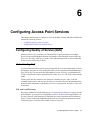
6 Configuring Access Point Services . . . . . . . . . . . . . . . . . . . . . . .69
Configuring Quality of Service (QoS) . . . . . . . . . . . . . . . . . . . . . . . . . . . .
69
Understanding QoS . . . . . . . . . . . . . . . . . . . . . . . . . . . . . . . . . . . . . . . . . . . . .
Configuring QoS Settings . . . . . . . . . . . . . . . . . . . . . . . . . . . . . . . . . . . . . . . .
69
75
Enabling the Network Time Protocol Server . . . . . . . . . . . . . . . . . . . . . . .
79
Enabling or Disabling a Network Time Protocol (NTP) Server . . . . . . . . . . .
80
7 Maintaining the Access Point . . . . . . . . . . . . . . . . . . . . . . . . . . .81
Managing the Configuration File . . . . . . . . . . . . . . . . . . . . . . . . . . . . . . . .
81
Resetting the Factory Default Configuration . . . . . . . . . . . . . . . . . . . . . . . . .
Saving the Current Configuration to a Backup File . . . . . . . . . . . . . . . . . . . .
Restoring the Configuration from a Previously Saved File . . . . . . . . . . . . . . .
Rebooting the Access Point . . . . . . . . . . . . . . . . . . . . . . . . . . . . . . . . . . . . . . .
82
83
83
85
Upgrading the Firmware . . . . . . . . . . . . . . . . . . . . . . . . . . . . . . . . . . . . . .
85
8 Configuring the Access Point for Managed Mode . . . . . . . . . .87
Transitioning Between Modes. . . . . . . . . . . . . . . . . . . . . . . . . . . . . . . . . . .
Configuring Managed Access Point Settings . . . . . . . . . . . . . . . . . . . . . . .
Viewing Managed AP DHCP Information . . . . . . . . . . . . . . . . . . . . . . . . .
87
88
89
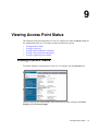
9 Viewing Access Point Status . . . . . . . . . . . . . . . . . . . . . . . . . . . .91
4
Viewing Interface Status . . . . . . . . . . . . . . . . . . . . . . . . . . . . . . . . . . . . . . .
91
Ethernet (Wired) Settings . . . . . . . . . . . . . . . . . . . . . . . . . . . . . . . . . . . . . . . . .
Wireless Settings . . . . . . . . . . . . . . . . . . . . . . . . . . . . . . . . . . . . . . . . . . . . . . .
92
92
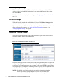
Viewing Events Logs . . . . . . . . . . . . . . . . . . . . . . . . . . . . . . . . . . . . . . . . .
92
Configuring Persistent Logging Options . . . . . . . . . . . . . . . . . . . . . . . . . . . . .
Configuring the Log Relay Host for Kernel Messages . . . . . . . . . . . . . . . . . .
Enabling or Disabling the Log Relay Host on the Events Page . . . . . . . . . . .
93
94
95
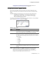
Viewing Transmit and Receive Statistics . . . . . . . . . . . . . . . . . . . . . . . . . .
Viewing Client Association Information . . . . . . . . . . . . . . . . . . . . . . . . . .
95
97
Link Integrity Monitoring . . . . . . . . . . . . . . . . . . . . . . . . . . . . . . . . . . . . . . . .
98
© 2001-2008 D-Link Corporation. All Rights Reserved.
Table of Contents
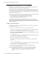
Viewing Neighboring Access Points . . . . . . . . . . . . . . . . . . . . . . . . . . . . .
98
A Wireless Client Settings and RADIUS Server Setup. . . . . . . 101
Accessing Wireless Client Security Settings . . . . . . . . . . . . . . . . . . . . . . .
Configuring a Client to Access an Unsecure Network . . . . . . . . . . . . . . .
Configuring Static WEP Security on a Client. . . . . . . . . . . . . . . . . . . . . .
Configuring WPA/WPA2 Personal on a Client . . . . . . . . . . . . . . . . . . . . .
Using an External Authentication Server . . . . . . . . . . . . . . . . . . . . . . . . .
Configuring IEEE 802.1X Security on a Client . . . . . . . . . . . . . . . . . . . .
102
104
104
106
108
108
IEEE 802.1X Client Using EAP/TLS Certificate. . . . . . . . . . . . . . . . . . . . . .
108
Configuring WPA/WPA2 Enterprise (RADIUS) . . . . . . . . . . . . . . . . . . . .
111
WPA/WPA2 Enterprise (RADIUS) Client Using EAP/PEAP . . . . . . . . . . . . . 111
WPA/WPA2 Enterprise (RADIUS) Client Using EAP-TLS Certificate . . . . . 113
Configuring the RADIUS Server for Authentication . . . . . . . . . . . . . . . .
Obtaining a TLS-EAP Certificate for a Client . . . . . . . . . . . . . . . . . . . . .
Configuring the RADIUS Server for VLAN Tags . . . . . . . . . . . . . . . . . . .
116
119
122
B CLI for AP Configuration . . . . . . . . . . . . . . . . . . . . . . . . . . . . 125
How to Access the Access Point CLI . . . . . . . . . . . . . . . . . . . . . . . . . . . .
125
Telnet Connection to the AP . . . . . . . . . . . . . . . . . . . . . . . . . . . . . . . . . . . . .
SSH Connection to the AP. . . . . . . . . . . . . . . . . . . . . . . . . . . . . . . . . . . . . . .
125
126
Commands and Syntax . . . . . . . . . . . . . . . . . . . . . . . . . . . . . . . . . . . . . . .
127
Using the get Command . . . . . . . . . . . . . . . . . . . . . . . . . . . . . . . . . . . . . . . .
Using the set Command. . . . . . . . . . . . . . . . . . . . . . . . . . . . . . . . . . . . . . . . .
Using the add Command . . . . . . . . . . . . . . . . . . . . . . . . . . . . . . . . . . . . . . . .
Using the remove Command . . . . . . . . . . . . . . . . . . . . . . . . . . . . . . . . . . . . .
Additional CLI Commands . . . . . . . . . . . . . . . . . . . . . . . . . . . . . . . . . . . . . .
128
128
129
129
130
Getting Help on Commands at the CLI . . . . . . . . . . . . . . . . . . . . . . . . . .
130
Tab Completion . . . . . . . . . . . . . . . . . . . . . . . . . . . . . . . . . . . . . . . . . . . . . . .
Keyboard Shortcuts . . . . . . . . . . . . . . . . . . . . . . . . . . . . . . . . . . . . . . . . . . . .
130
131
Interface Naming Conventions . . . . . . . . . . . . . . . . . . . . . . . . . . . . . . . . .
Saving Configuration Changes . . . . . . . . . . . . . . . . . . . . . . . . . . . . . . . . .
Access Point CLI Commands . . . . . . . . . . . . . . . . . . . . . . . . . . . . . . . . . .
132
133
133
Configuring Basic Settings . . . . . . . . . . . . . . . . . . . . . . . . . . . . . . . . . . . . . .
Status . . . . . . . . . . . . . . . . . . . . . . . . . . . . . . . . . . . . . . . . . . . . . . . . . . . . . . .
Ethernet Settings . . . . . . . . . . . . . . . . . . . . . . . . . . . . . . . . . . . . . . . . . . . . . .
Wireless Interface . . . . . . . . . . . . . . . . . . . . . . . . . . . . . . . . . . . . . . . . . . . . .
Radio Settings . . . . . . . . . . . . . . . . . . . . . . . . . . . . . . . . . . . . . . . . . . . . . . . .
Virtual Access Points. . . . . . . . . . . . . . . . . . . . . . . . . . . . . . . . . . . . . . . . . . .
Managed Access Point . . . . . . . . . . . . . . . . . . . . . . . . . . . . . . . . . . . . . . . . .
IEEE 802.1X Supplicant Authentication . . . . . . . . . . . . . . . . . . . . . . . . . . . .
Quality of Service . . . . . . . . . . . . . . . . . . . . . . . . . . . . . . . . . . . . . . . . . . . . .
Time . . . . . . . . . . . . . . . . . . . . . . . . . . . . . . . . . . . . . . . . . . . . . . . . . . . . . . . .
System Management . . . . . . . . . . . . . . . . . . . . . . . . . . . . . . . . . . . . . . . . . . .
134
135
136
137
138
139
146
147
147
149
149
CLI Classes and Properties Reference . . . . . . . . . . . . . . . . . . . . . . . . . . .
150
Glossary . . . . . . . . . . . . . . . . . . . . . . . . . . . . . . . . . . . . . . . . . . . . . 151
5
D-Link Unified Access Point Administrator’s Guide
6
© 2001-2008 D-Link Corporation. All Rights Reserved.
List of Figures
List of Figures
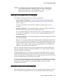
Figure 1. Administrator UI Online Help............................................................... 13
Figure 2. LAN Connection for DHCP-Assigned IP ............................................. 26
Figure 3. Ethernet Connection for Static IP Assignment...................................... 26
Figure 4. Basic Settings ........................................................................................ 28
Figure 5. LAN Interface Configuration ................................................................ 31
Figure 6. IEEE 802.1X Authentication................................................................. 35
Figure 7. Virtual Access Point Page. .................................................................... 44
Figure 8. Static WEP Configuration ..................................................................... 45
Figure 9. Static WEP Example ............................................................................. 48
Figure 10. Providing a Wireless Client with a WEP Key..................................... 49
Figure 11. IEEE 802.1X Configuration ................................................................ 50
Figure 12. WPA Personal Configuration .............................................................. 51
Figure 13. WPA Enterprise Configuration ........................................................... 52
Figure 14. Wireless Interface Configuration ........................................................ 55
Figure 15. Traffic Prioritization............................................................................ 74
Figure 16. Configuration Management................................................................. 82
Figure 17. Managed Access Point Settings .......................................................... 88
Figure 18. Viewing and Configuring System Events ........................................... 92
7
D-Link Unified Access Point Administrator’s Guide
8
© 2001-2008 D-Link Corporation. All Rights Reserved.
List of Tables
List of Tables
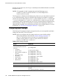
Table 1. Typographical Conventions . . . . . . . . . . . . . . . . . . . . . . . . . . . . . . . . . . 12
Table 2. AP Default Settings . . . . . . . . . . . . . . . . . . . . . . . . . . . . . . . . . . . . . . . . 19
Table 3. Requirements for the Administrator’s Computer . . . . . . . . . . . . . . . . . 21
Table 4. Requirements for Wireless Clients . . . . . . . . . . . . . . . . . . . . . . . . . . . . 22
Table 5. Reset Button . . . . . . . . . . . . . . . . . . . . . . . . . . . . . . . . . . . . . . . . . . . . . . 23
Table 6. Basic Settings . . . . . . . . . . . . . . . . . . . . . . . . . . . . . . . . . . . . . . . . . . . . . 29
Table 7. Ethernet Settings . . . . . . . . . . . . . . . . . . . . . . . . . . . . . . . . . . . . . . . . . . 31
Table 8. CLI Commands for Ethernet Settings . . . . . . . . . . . . . . . . . . . . . . . . . . 33
Table 9. IEEE 802.1X Supplicant Authentication . . . . . . . . . . . . . . . . . . . . . . . . 35
Table 10. CLI Commands for the 802.1X Supplicant . . . . . . . . . . . . . . . . . . . . . 36
Table 11. Static WEP . . . . . . . . . . . . . . . . . . . . . . . . . . . . . . . . . . . . . . . . . . . . . . 46
Table 12. IEEE 802.1X . . . . . . . . . . . . . . . . . . . . . . . . . . . . . . . . . . . . . . . . . . . . 50
Table 13. WPA Personal . . . . . . . . . . . . . . . . . . . . . . . . . . . . . . . . . . . . . . . . . . . 51
Table 14. WPA Enterprise . . . . . . . . . . . . . . . . . . . . . . . . . . . . . . . . . . . . . . . . . . 52
Table 15. Wireless Settings . . . . . . . . . . . . . . . . . . . . . . . . . . . . . . . . . . . . . . . . . 56
Table 16. Radio Settings . . . . . . . . . . . . . . . . . . . . . . . . . . . . . . . . . . . . . . . . . . . 59
Table 17. VAP Configuration . . . . . . . . . . . . . . . . . . . . . . . . . . . . . . . . . . . . . . . 63
Table 18. MAC Authentication . . . . . . . . . . . . . . . . . . . . . . . . . . . . . . . . . . . . . . 67
Table 19. RADIUS Server Attributes for MAC Authentication . . . . . . . . . . . . . 67
Table 20. Load Balancing . . . . . . . . . . . . . . . . . . . . . . . . . . . . . . . . . . . . . . . . . . 68
Table 21. VLAN Priority Tags . . . . . . . . . . . . . . . . . . . . . . . . . . . . . . . . . . . . . . 74
Table 22. QoS Settings . . . . . . . . . . . . . . . . . . . . . . . . . . . . . . . . . . . . . . . . . . . . 76
Table 23. SNTP Settings . . . . . . . . . . . . . . . . . . . . . . . . . . . . . . . . . . . . . . . . . . . 80
Table 24. Managed Access Point . . . . . . . . . . . . . . . . . . . . . . . . . . . . . . . . . . . . . 88
Table 25. Logging Options . . . . . . . . . . . . . . . . . . . . . . . . . . . . . . . . . . . . . . . . . 93
Table 26. Log Relay Host . . . . . . . . . . . . . . . . . . . . . . . . . . . . . . . . . . . . . . . . . . 95
Table 27. Transmit/Receive Statistics . . . . . . . . . . . . . . . . . . . . . . . . . . . . . . . . . 96
Table 28. Associated Clients . . . . . . . . . . . . . . . . . . . . . . . . . . . . . . . . . . . . . . . . 97
Table 29. Neighboring Access Points . . . . . . . . . . . . . . . . . . . . . . . . . . . . . . . . . 99
Table 30. Wireless Client with No Security . . . . . . . . . . . . . . . . . . . . . . . . . . . 104
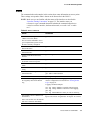
Table 31. Additional CLI Commands . . . . . . . . . . . . . . . . . . . . . . . . . . . . . . . . 130
Table 32. Keyboard Shortcuts . . . . . . . . . . . . . . . . . . . . . . . . . . . . . . . . . . . . . . 131
Table 33. Interface Naming Convention . . . . . . . . . . . . . . . . . . . . . . . . . . . . . . 132
Table 34. Basic Setting Commands . . . . . . . . . . . . . . . . . . . . . . . . . . . . . . . . . . 134
Table 35. Status Commands . . . . . . . . . . . . . . . . . . . . . . . . . . . . . . . . . . . . . . . 135
Table 36. Ethernet Setting Commands . . . . . . . . . . . . . . . . . . . . . . . . . . . . . . . 136
Table 37. Wireless Setting Commands . . . . . . . . . . . . . . . . . . . . . . . . . . . . . . . 137
Table 38. Radio Setting Commands . . . . . . . . . . . . . . . . . . . . . . . . . . . . . . . . . 138
Table 39. VAP Commands . . . . . . . . . . . . . . . . . . . . . . . . . . . . . . . . . . . . . . . . 139
Table 40. Managed Access Point Commands . . . . . . . . . . . . . . . . . . . . . . . . . . 146
Table 41. IEEE 802.1X Supplicant Commands . . . . . . . . . . . . . . . . . . . . . . . . 147
Table 42. QoS Commands . . . . . . . . . . . . . . . . . . . . . . . . . . . . . . . . . . . . . . . . . 147
Table 43. Valid Queue Name Values . . . . . . . . . . . . . . . . . . . . . . . . . . . . . . . . 148
9
D-Link Unified Access Point Administrator’s Guide
Table 44. Time Related Commands . . . . . . . . . . . . . . . . . . . . . . . . . . . . . . . . . 149
Table 45. System Management . . . . . . . . . . . . . . . . . . . . . . . . . . . . . . . . . . . . . 149
Table 46. CLI Class Instances . . . . . . . . . . . . . . . . . . . . . . . . . . . . . . . . . . . . . . 150
10
© 2001-2008 D-Link Corporation. All Rights Reserved.
About This Document
About This Document
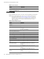
This guide describes setup, configuration, administration and maintenance for the D-Link
DWL-3500AP and DWL-8500AP access points on a wireless network.
Document Organization
The D-Link Access Point Administrator’s Guide contains the following information:
•
•
•
•
•
•
•
•
•
•
•
Chapter 1, "Overview of the D-Link Access Point"
Chapter 2, "Preparing to Install the Access Point"
Chapter 3, "Installing the Access Point"
Chapter 4, "Configuring Access Point Security"
Chapter 5, "Managing the Access Point"
Chapter 6, "Configuring Access Point Services"
Chapter 7, "Maintaining the Access Point"
Chapter 8, "Configuring the Access Point for Managed Mode"
Chapter 9, "Viewing Access Point Status"
Appendix A, "Wireless Client Settings and RADIUS Server Setup"
Appendix B, "CLI for AP Configuration"
Audience
This guide is intended for the following audience:
•
•
System administrators who are responsible for configuring and operating a network using
D-Link Access Point software
Level 1 and/or Level 2 Support providers
To obtain the greatest benefit from this guide, you should also have basic knowledge of
Ethernet and wireless networking concepts.
Document Conventions
This section describes the conventions this document uses.
NOTE: A Note provides more information about a feature or technology and crossreferences to related topics.
CAUTION: A Caution provides information about critical aspects of AP
configuration, combinations of settings, events, or procedures that can
adversely affect network connectivity, security, and so on.
Document Organization
11
D-Link Unified Access Point Administrator’s Guide
This guide uses the typographical conventions that Table 1 describes.
Table 1. Typographical Conventions
Symbol
Example
Description
Bold
Click Update to save your
settings.
Menu titles, page names, and button names
Blue Text
See “Document
Conventions” on page 11.
Hyperlinked text.
courier font
WLAN-AP#
Screen text, file names.
courier bold
show network
Commands, user-typed command-line entries
courier font
italics
value
Command parameter, which might be a
variable or fixed value.
<> Angle brackets
<value>
Indicates a parameter is a variable. You must
enter a value in place of the brackets and text
inside them.
[ ] Square brackets
[value]
Indicates an optional fixed parameter.
[< >] Angle
brackets within
square brackets
[<value>]
Indicates an optional variable.
{} curly braces
{choice1 | choice2}
Indicates that you must select a parameter
from the list of choices.
| Vertical bars
choice1 | choice2
Separates the mutually exclusive choices.
[{}] Braces within
square brackets
[{choice1 | choice2}]
Indicate a choice within an optional element.
Online Help, Supported Browsers, and Limitations
Online help for the D-Link AP Administration Web pages provides information about all
fields and features available from the user interface (UI). The information in the online help is
a subset of the information available in the D-Link Access Point Administrator’s Guide.
Online help information corresponds to each page on the D-Link Access Point Administration
UI.
For information about the settings on the current page, click the
a page or the More... link at the bottom of the help panel on the UI.
12
© 2001-2008 D-Link Corporation. All Rights Reserved.
link on the right side of
About This Document
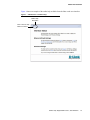
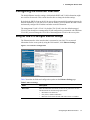
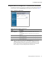
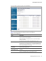
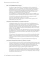
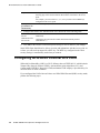
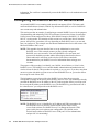
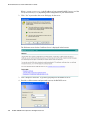
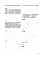
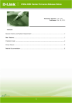
Figure 1 shows an example of the online help available from the links on the user interface.
Figure 1. Administrator UI Online Help
Online Help
Navigation
Click to Access Help
Table of Contents
Online Help, Supported Browsers, and Limitations
13
D-Link Unified Access Point Administrator’s Guide
14
© 2001-2008 D-Link Corporation. All Rights Reserved.
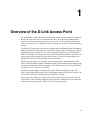
1
Overview of the D-Link Access Point
The D-Link DWL-3500AP and DWL-8500AP access points provide continuous, high-speed
access between wireless devices and Ethernet devices. It is an advanced, standards-based
solution for wireless networking in businesses of any size. The D-Link AP enables wireless
local area network (WLAN) deployment while providing state-of-the-art wireless networking
features.
The D-Link AP can operate in two modes: Standalone Mode or Managed Mode. In Standalone
Mode, the AP acts as an individual access point in the network, and you manage it by using the
Administrator Web User Interface (UI) or the command-line interface (CLI). In Managed
Mode, the Unified Access Point is part of the D-Link Unified Wired/Wireless Access System,
and you manage it by using the D-Link Unified Switch. If an AP is in Managed Mode, the
Administrator Web UI, Telnet, and SSH services are disabled.
This document describes how to perform the setup, management, and maintenance of the
DWL-3500AP and DWL-8500AP in Standalone Mode. For information about configuring the
access points in Managed Mode by using the D-Link Unified Switch, see the D-Link Unified
Wired/Wireless Access System User Manual.
The DWL-3500AP supports one radio, and the DWL-8500AP supports two radios. The
DWL-3500AP radio and one of the DWL-8500AP radios operate in IEEE 802.11g mode. The
second radio on the DWL-8500AP operates in IEEE 802.11a mode.
Each access point supports up to eight virtual access points (VAPs) on each radio. The VAP
feature allows you to segment each physical access point into eight logical access points (per
radio) that each support a unique SSID, VLAN ID, and security policy.
15
D-Link Unified Access Point Administrator’s Guide
Features and Benefits
This section lists the DWL-3500AP and DWL-8500AP features and benefits, which are in the
following categories:
•
•
•
•
•
•
IEEE Standards Support
Wireless Features
Security Features
Networking
Maintainability
Access Point Hardware
IEEE Standards Support
The DWL-3500AP comes configured as a single-band access point with one radio and is
capable of broadcasting in the following modes:
•
•
•
IEEE 802.11b mode
IEEE 802.11g mode
Dynamic Turbo 2.4 GHz
The DWL-8500AP comes configured as a dual-band access point with two radios and is
capable of broadcasting in the following modes:
•
•
•
•
•
IEEE 802.11b mode
IEEE 802.11g mode
IEEE 802.11a mode
Dynamic Turbo 5 GHz
Dynamic Turbo 2.4 GHz
The DWL-3500AP and DWL-8500AP access points provide bandwidth of up to 54 Mbps for
IEEE 802.11a or IEEE 802.11g, 108 Mbps for IEEE 802.11a Turbo, and 11 Mbps for IEEE
802.11b.
Wireless Features
The following list describes some of the DWL-3500AP and DWL-8500AP wireless features:
•
•
•
•
•
•
•
•
•
•
•
16
Auto channel selection at startup
Transmit power adjustment
Quality of Service (QoS) for enhanced throughput and better performance of timesensitive wireless traffic like Video, Audio, Voice over IP (VoIP) and streaming media
Wi-Fi Multimedia (WMM) compliance for QoS
Load Balancing
Built-in support for multiple SSIDs (network names) and multiple BSSIDs (basic service
set IDs) on the same access point
Channel management for automatic coordination of radio channel assignments to reduce
AP-to-AP interference on the network and maximize Wi-Fi bandwidth
Neighboring access point detection (also known as “rogue” AP detection)
Support for IEEE 802.11d Regulatory Domain selection (country codes for global operation)
Support for IEEE 802.11h, incorporating TPC and DFS
Support for Super AG technology, which can increase WLAN speed and throughput
© 2001-2008 D-Link Corporation. All Rights Reserved.
1 Overview of the D-Link Access Point
•
SpectraLink Voice Priority (SVP)
SpectraLink Voice Priority (SVP) is a QoS approach for Wi-Fi deployments. SVP is an
open specification that is compliant with the IEEE 802.11b standard. SVP minimizes
delay and prioritizes voice packets over data packets on the WLAN, which increases the
probability of better network performance.
Security Features
The DWL-3500AP and DWL-8500AP access points provide several different security levels
and options:
•
•
•
•
•
•
•
•
•
•
•
•
Prevent SSID Broadcast
Weak Initialization Vector (IV) avoidance
Wireless Equivalent Privacy (WEP)
Wi-Fi Protected Access (WPA/WPA2)
WPA Personal
WPA Enterprise
IEEE 802.11i Architecture Support
Advanced Encryption Standard (AES)
MAC address filtering
Secure Sockets Shell (SSH)
Secure Sockets Layer (SSL)
IEEE 802.1X Supplicant
Networking
The DWL-3500AP and DWL-8500AP access points have the following networking features:
•
•
•
•
•
•
Point-to-Point bridge mode
Point-to-Multipoint bridge mode
Repeater mode
Dynamic Host Configuration Protocol (DHCP) support for dynamically obtaining
network configuration information.
Virtual Local Area Network (VLAN) support
Eight virtual access points (VAPs) per radio
For each VAP, you can configure a unique SSID name, a default VLAN ID, a security
mode, external RADIUS server information, and radio association. Additionally, you can
configure dynamic VLANs on an external RADIUS server.
•
•
•
HTTP, HTTPS, Telnet, and SSH
Spanning Tree Protocol (STP)
802.1p
Maintainability
You can perform many maintenance and monitoring tasks from the DWL-3500AP and DWL8500AP Administrator Web UI:
•
Status, monitoring, and tracking views of the network including session monitoring, client
associations, transmit/receive statistics, and event log
Features and Benefits
17
D-Link Unified Access Point Administrator’s Guide
•
•
•
•
Link integrity monitoring to continually verify connection to the client, regardless of
network traffic activity levels
Reset configuration option
Firmware upgrade by using HTTP or TFTP
Backup and restore of access point configuration by using HTTP or TFTP
Access Point Hardware
The Unified Access Point software supports the following hardware features:
•
•
Power port and power adapter
Reset button
For more information about the specifics of your Access Point, see the information provided
by the manufacturer.
18
© 2001-2008 D-Link Corporation. All Rights Reserved.
2
Preparing to Install the Access Point
Before you power on a new D-Link Access Point, review the following sections to check
required hardware and software components, client configurations, and compatibility issues.
Make sure you have everything you need for a successful launch and test of your new or
extended wireless network.
This chapter contains the following sections:
•
•
•
•
•
Default Settings for the Unified Access Points
Administrator’s Computer Requirements
Wireless Client Requirements
Dynamic and Static IP Addressing on the AP
Using the Reset Button
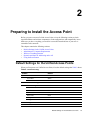
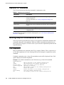
Default Settings for the Unified Access Points
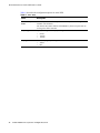
When you first power on a Unified Access Point, it has the default settings that Table 2 shows
Table 2. AP Default Settings
Feature
Default
System Information
User Name
admin
Password
admin
Ethernet Interface Settings
Connection Type
DHCP
DHCP
Enabled
IP Address
10.90.90.91 (if no DHCP server is available)
Subnet Mask
255.0.0.0
DNS Name
None
Management VLAN ID
1
Untagged VLAN ID
1
Radio Settings: DWL-8500AP
Radio (1 and 2)
On
Default Settings for the Unified Access Points
19
D-Link Unified Access Point Administrator’s Guide
Table 2. AP Default Settings
Feature
Default
Radio 1 IEEE 802.11 Mode
802.11a
Radio 2 IEEE 802.11 Mode
802.11g
802.11b/g Channel
Auto
802.11a Channel
Auto
Radio Settings: DWL-3500AP
Radio
On
Radio IEEE 802.11 Mode
802.11g
802.11b/g Channel
Auto
Radio Settings: DWL-3500 AP and DWL-8500AP
Beacon Interval
100
DTIM Period
2
Fragmentation Threshold
2346
RTS Threshold
2347
MAX Wireless Clients
256
Transmit Power
100 percent
Rate Sets
Supported (Mbps)
IEEE 802.1a: 54, 48, 36, 24, 18, 12, 9, 6
IEEE 802.1g: 54, 48, 36, 24, 18, 12, 11, 9, 6, 5.5, 2, 1
Turbo 5 GHz: 108, 96, 72, 48, 36, 24, 18, 12
Rate Sets (Mbps)
(Basic/Advertised)
IEEE 802.1a: 24, 12, 6
IEEE 802.1g: 11, 5.5, 2, 1
Turbo 5 GHz: 48, 24, 12
Virtual Access Point Settings
20
Status
VAP0 is enabled on both radios, all other VAPs disabled
Network Name (SSID)
“DLINK VAP” for VAP0
SSID for all other VAPs is “Virtual Access Point x”
where x is the VAP number.
Broadcast SSID
Allow
Security Mode
None (plain text)
Authentication Type
None
RADIUS IP Address
10.90.90.1
RADIUS Key
secret
RADIUS Accounting
Disabled
© 2001-2008 D-Link Corporation. All Rights Reserved.
2 Preparing to Install the Access Point
Table 2. AP Default Settings
Feature
Default
Other Default Settings
MAC Authentication
No stations in list
Load Balancing
Disabled
Managed Mode
Disabled
HTTP Access
Enabled; disabled in Managed Mode
HTTPS Access
Enabled; disabled in Managed Mode
Telnet Access
Enabled; disabled in Managed Mode
SSH Access
Enabled; disabled in Managed Mode
802.1X Supplicant
Disabled
WMM
Enabled
Network Time Protocol (NTP)
None
NOTE: The Unified Access Point is not designed to function as a Gateway to the
Internet. To connect your Wireless LAN (WLAN) to other LANs or the
Internet, you need a gateway device.
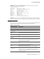
Administrator’s Computer Requirements
The following table describes the minimum requirements for the administrator’s computer for
configuration and administration of the Unified Access Point through a Web-based user
interface (UI).
Table 3. Requirements for the Administrator’s Computer
Required Software
or Component
Description
Ethernet Connection to
the Access Point
The computer used to configure the first access point must be connected
to the access point by an Ethernet cable.
For more information on this step, see “Installing the Access Point” on
page 25.
Wireless Connection to
the Network
After initial configuration and launch of the first access point on your new
wireless network, you can make subsequent configuration changes
through the Administration Web pages using a wireless connection to the
internal network. For wireless connection to the access point, your
administration device will need Wi-Fi capability similar to that of any
wireless client:
•
•
Portable or built-in Wi-Fi client adapter that supports one or more of
the IEEE 802.11 modes in which you plan to run the access point.
Wireless client software configured to associate with the Unified
Access Point.
Administrator’s Computer Requirements
21
D-Link Unified Access Point Administrator’s Guide
Table 3. Requirements for the Administrator’s Computer
Required Software
or Component
Web Browser and
Operating System
Description
Configuration and administration of the Unified Access Point is provided
through a Web-based user interface hosted on the access point. We
recommend using Microsoft Internet Explorer version 6.0 or7.x (with upto-date patch level for either major version) on Microsoft Windows XP or
Microsoft Windows 2000
The administration Web browser must have JavaScript enabled to support
the interactive features of the administration interface.
Security Settings
Ensure that security is disabled on the wireless client used to initially
configure the access point.
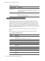
Wireless Client Requirements
The DWL-3500AP and DWL-8500AP provide wireless access to any client with a properly
configured Wi-Fi client adapter for the 802.11 mode in which the access point is running. The
AP supports multiple client operating systems. Clients can be laptop or desktop computers,
personal digital assistants (PDAs), or any other hand-held, portable or stationary device
equipped with a Wi-Fi adapter and supporting drivers.
In order to connect to the access point, wireless clients need the software and hardware
described in Table 4.
Table 4. Requirements for Wireless Clients
Required
Component
Description
Wi-Fi Client
Adapter
Portable or built-in Wi-Fi client adapter that supports one or more of the IEEE
802.11 modes in which you plan to run the access point. (IEEE 802.11a,
802.11b, 802.11g, and Dynamic Turbo modes are supported.)
Wireless Client
Software
Client software, such as Microsoft Windows Supplicant, configured to
associate with the Unified Access Point.
Client Security
Settings
Security should be disabled on the client used to do initial configuration of the
access point.
If the Security mode on the access point is set to anything other than plain text,
wireless clients will need to set a profile to the authentication mode used by the
access point and provide a valid username and password, certificate, or similar
user identity proof. Security modes are Static WEP, IEEE 802.1X, WPA with
RADIUS server, and WPA-PSK.
For information about configuring security on the access point, see
“Configuring Access Point Security” on page 39.
22
© 2001-2008 D-Link Corporation. All Rights Reserved.
2 Preparing to Install the Access Point
Dynamic and Static IP Addressing on the AP
When you power on the access point, the built-in DHCP client searches for a DHCP server on
the network in order to obtain an IP Address and other network information. If the AP does not
find a DHCP server on the network, the AP continues to use its default Static IP Address
(10.90.90.91) until you re-assign it a new static IP address (and specify a static IP addressing
policy) or until the AP successfully receives network information from a DHCP server.
To change the connection type and assign a static IP address, see “Configuring the Ethernet
Interface” on page 31.
CAUTION: If you do not have a DHCP server on your internal network and do not
plan to use one, the first thing you must do after powering on the access
point is change the connection type from DHCP to static IP. You can
either assign a new static IP address to the AP or continue using the
default address. We recommend assigning a new static IP address so that
if you bring up another Unified Access Point on the same network, the IP
address for each AP will be unique.
Recovering an IP Address
If you experience trouble communicating with the access point, you can recover a static IP
address by resetting the AP configuration to the factory defaults (see “Resetting the Factory
Default Configuration” on page 82), or you can get a dynamically assigned address by
connecting the AP to a network that has a DHCP server.
Discovering a Dynamically Assigned IP Address
If you have access to the DHCP server on your network and know the MAC address of your
AP, you can view the new IP address associated with the MAC address of the AP.
If you do not have access to the DHCP server that assigned the IP address to the AP or do not
know the MAC address of the AP, you might need to use the CLI to find out what the new IP
address is. For information about how to discover a dynamically assigned IP address, see
“Using the CLI to View the IP Address” on page 30.
Using the Reset Button
The reset button is located on the rear panel of the access point and is labeled Reset. Use the
reset button to manually reboot the AP or to reset the AP back to the factory default settings,
as Table 5 describes.
Table 5. Reset Button
Function
Action
Reboot
Press reset button for < 2 seconds
Reset to factory defaults
Press and hold reset button for > 5 seconds
Dynamic and Static IP Addressing on the AP
23
D-Link Unified Access Point Administrator’s Guide
24
© 2001-2008 D-Link Corporation. All Rights Reserved.
3
Installing the Access Point
This chapter describes the basic steps required to setup and deploy the D-Link Access Point
and contains the following sections:
•
•
•
•
•
Installing the Unified Access Point
Using the CLI to View the IP Address
Configuring the Ethernet Interface
Configuring IEEE 802.1X Authentication
Verifying the Installation
To manage the DWL-3500AP and DWL-8500AP access points by using the Web interface or
by using the CLI through Telnet or SSH, the AP needs an IP address. If you use VLANs or
IEEE 802.1X Authentication (port security) on your network, you might need to configure
additional settings on the AP before it can connect to the network.
Installing the Unified Access Point
To access the Administration Web UI, you enter the IP address of the access point into a Web
browser. You can use the default IP address of the AP (10.90.90.91) to log on to the AP and
assign a static IP address, or you can use a DHCP server on you network to assign network
information to the AP. The DHCP client on the AP is enabled by default.
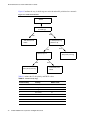
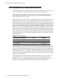
To install the Unified Access Point, use the following steps:
1. Connect the access point to an administrative PC by using a LAN connection or a directcable connection.
Installing the Unified Access Point
25
D-Link Unified Access Point Administrator’s Guide
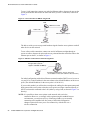
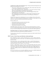
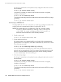
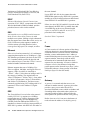
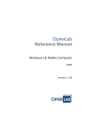
To use a LAN connection, connect one end of an Ethernet cable to the network port on the
access point and the other end to the same hub where your PC is connected, as shown in
Figure 2.
Figure 2. LAN Connection for DHCP-Assigned IP
HUB
Admin PC to Hub
AP to Hub
Hub to LAN
LAN
Administrator Computer
Access Point
The hub or switch you use must permit broadcast signals from the access point to reach all
other devices on the network.
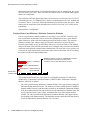
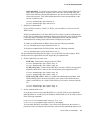
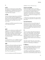
To use a direct-cable connection, connect one end of an Ethernet straight-through or
crossover cable to the network port on the access point and the other end of the cable to the
Ethernet port on the PC, as shown in Figure 3.
Figure 3. Ethernet Connection for Static IP Assignment
Crossover Cable (or straightthrough cable if your AP
supports auto MDI and MDI-X)
(For Ethernet connections, This PC must have
an IP address on the same subnet as Access Point.)
For initial configuration with a direct Ethernet connection and no DHCP server, be sure to
set your PC to a static IP address in the same subnet as the default IP address on the access
point. (The default IP address for the access point is 10.90.90.91.)
If you use this method, you will need to reconfigure the cabling for subsequent startup and
deployment of the access point so that the access point is no longer connected directly to
the PC but instead is connected to the LAN (either by using a hub, as shown in Figure 2 or
directly).
NOTE: It is possible to detect access points on the network with a wireless
connection. However, we strongly advise against using this method. In most
environments, you may have no way of knowing whether you are actually
connecting to the intended AP. Also, many of the initial configuration
changes required will cause you to lose connectivity with the AP over a
wireless connection.
26
© 2001-2008 D-Link Corporation. All Rights Reserved.
3 Installing the Access Point
2. Connect the power adapter to the power port on the back of the access point, and then plug
the other end of the power cord into a power outlet.
3. Use your Web browser to log on to the access point Administration Web pages.
If the AP did not acquire an IP address from a DHCP server on your network, enter
10.90.90.91 in the address field of your browser, which is the default IP address of the AP.
If you used a DHCP server on your network to automatically configure network
information for the AP, enter the new IP address of the AP into the Web browser.
If you used a DHCP server and you do not know the new IP address of the AP, use the
following procedures to obtain the information:
A. Connect a serial cable from the administrative computer to the AP and use a terminal
emulation program to access the command-line interface (CLI).
B. At the login prompt, enter admin for the user name and admin for the password. At the
command prompt, enter:
get management
The command output displays the IP address of the AP. Enter this address in the
address field of your browser.
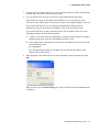
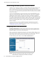
4. When prompted, enter admin for the user name and admin for the password, then click
OK.
When you first log in, the Basic Settings page for the Unified Access Point administration
is displayed.
Installing the Unified Access Point
27
D-Link Unified Access Point Administrator’s Guide
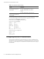
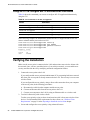
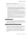
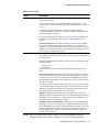
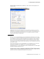
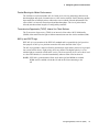
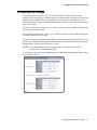
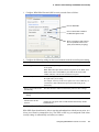
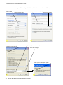
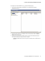
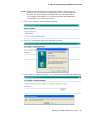
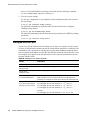
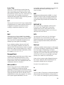
5. Verify the settings on the Basic Settings page.
Figure 4. Basic Settings
A. Review access point description and provide a new administrator password for the
access point if you do not want to use the default password, which is admin.
B. Click the Update button to activate the wireless network with these new settings.
NOTE: The changes you make are not saved or applied until you click Update.
Changing some access point settings might cause the AP to stop and restart
system processes. If this happens, wireless clients will temporarily lose
connectivity. We recommend that you change access point settings when
WLAN traffic is low.
For more information about the fields and configuration options on the Basic Settings
page, see “Viewing Basic Settings” on page 29.
6. If you do not have a DHCP server on the management network and do not plan to use one,
you must change the Connection Type from DHCP to Static IP.
You can either assign a new Static IP address to the AP or continue using the default
address. We recommend assigning a new Static IP address so that if you bring up another
Unified Access Point on the same network, the IP address for each AP will be unique. To
change the connection type and assign a static IP address, see “Configuring the Ethernet
Interface” on page 31.
28
© 2001-2008 D-Link Corporation. All Rights Reserved.
3 Installing the Access Point
7. If your network uses VLANs, you might need to configure the management VLAN ID or
untagged VLAN ID on the D-Link Access Point in order for it to work with your network.
For information about how to configure VLAN information, see “Configuring the
Ethernet Interface” on page 31.
8. If your network uses IEEE 802.1X port security for network access control, you must
configure the 802.1X supplicant information on the AP.
For information about how to configure the 802.1X user name and password, see
“Configuring IEEE 802.1X Authentication” on page 34.
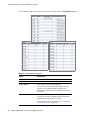
Viewing Basic Settings
From the Basic Settings page, you can view IP and MAC address information and configure
the administrator password for the access point. Table 6 describes the fields and configuration
options on the Basic Settings page.
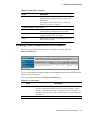
Table 6. Basic Settings
Field
Description
IP Address
Shows the IP address assigned to the AP. This field is not editable on this
page because the IP address is already assigned (either by DHCP, or
statically through the Ethernet Settings page as described in
“Configuring the Ethernet Interface” on page 31).
MAC Address
Shows the MAC address of the access point.
The address shown here is the MAC address associated with the
management interface. This is the address by which the AP is known
externally to other networks.
Serial Number
Shows the serial number of the AP.
Firmware Version
Shows version information about the firmware currently installed on the
access point.
As new versions of the Unified Access Point firmware become available,
you can upgrade the firmware on your access points. For instructions
about how to upgrade the firmware, see “Upgrading the Firmware” on
page 85.
Current Password
Enter the current administrator password. You must correctly enter the
current password before you are able to change it.
New Password
Enter a new administrator password. The characters you enter are
displayed as “*” characters to prevent others from seeing your password
as you type.
The administrator password must be an alphanumeric string of up to 8
characters. Do not use special characters or spaces.
NOTE: As an immediate first step in securing your wireless network, we
recommend that you change the administrator password from the default.
Confirm New
Password
Re-enter the new administrator password to confirm that you typed it as
intended.
Installing the Unified Access Point
29
D-Link Unified Access Point Administrator’s Guide
Using the CLI to View the IP Address
The DHCP client on the Unified Access Point is enabled by default. If you connect the access
point to a network with a DHCP server, the AP automatically acquires an IP address. To
manage the access point by using the Administrator UI, you must enter the IP address of the
access point into a Web browser.
If a DHCP server on your network assigns an IP address to the access point, and you do not
know the IP address, use the following steps to view the IP address of the access point:
1. Using a null-modem cable, connect a VT100/ANSI terminal or a workstation to the
console (serial) port.
If you attached a PC, Apple, or UNIX workstation, start a terminal-emulation program,
such as HyperTerminal or TeraTerm.
2. Configure the terminal-emulation program to use the following settings:
- Baud rate: 115200 bps
- Data bits: 8
- Parity: none
- Stop bit: 1
- Flow control: none
3. Press the return key, and a login prompt should appear.
The login name is admin. The default password is admin.
After a successful login, the screen shows the (Access Point Name)# prompt.
4. At the login prompt, enter get management.
Information similar to the following prints to the screen:.
30
© 2001-2008 D-Link Corporation. All Rights Reserved.
3 Installing the Access Point
Configuring the Ethernet Interface
The default Ethernet interface settings, which include DHCP and VLAN information, might
not work for all networks. This section describes how to change the default settings.
By default, the DHCP client on the D-Link Access Point automatically broadcasts requests for
network information. If you want to use a static IP address, you must disable the DHCP client
and manually configure the IP address and other network information.
The management VLAN is VLAN 1 by default. This VLAN is also the default untagged
VLAN. If you already have a management VLAN configured on your network with a different
VLAN ID, you must change the VLAN ID of the management VLAN on the access point.
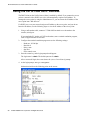
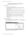
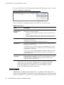
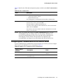
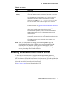
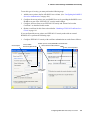
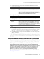
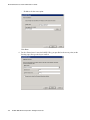
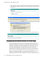
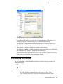
Using the Web UI to configure Ethernet Settings
The Ethernet interface is the interface that is connected to your LAN. To set network
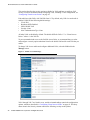
information for the access point by using the Web interface, click Ethernet Settings.
Figure 5. LAN Interface Configuration
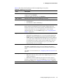
Table 7 describes the fields and configuration options on the Ethernet Settings page.
Table 7. Ethernet Settings
Field
Description
DNS Name
Enter the DNS name (host name) for the access point in the text box.
The DNS name has the following requirements:
•
•
•
Maximum of 20 characters
Only letters, numbers and dashes
Must start with a letter and end with either a letter or a number.
Configuring the Ethernet Interface
31
D-Link Unified Access Point Administrator’s Guide
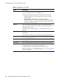
Table 7. Ethernet Settings
Field
Description
MAC Address
Shows the MAC address for the LAN interface for the Ethernet port on
this access point. This is a read-only field that you cannot change.
Management VLAN ID
The management VLAN is the VLAN associated with the IP address
you use to access the AP. The default management VLAN ID is 1.
Provide a number between 1 and 4094 for the management VLAN ID.
Untagged VLAN
If you disable untagged VLANs, all traffic is tagged with a VLAN ID.
By default all traffic on the Unified Access Point uses VLAN 1, which
is the default untagged VLAN.
This means that all traffic is untagged until you disable untagged
VLANs, change the untagged traffic VLAN ID, or change the VLAN
ID for a virtual access point (VAP) or a client using RADIUS.
Untagged VLAN ID
Provide a number between 1 and 4094 for the untagged VLAN ID.
Traffic on the VLAN that you specify in this field will not be tagged
with a VLAN ID.
Connection Type
If you select DHCP, the access point acquires its IP address, subnet
mask, DNS, and gateway information from a DHCP server.
If you select Static IP, you must enter information in the Static IP
Address, Subnet Mask, and Default Gateway fields.
Static IP Address
Enter the static IP address in the text boxes. This field is disabled if you
use DHCP as the connection type.
Subnet Mask
Enter the subnet mask in the text boxes.
Default Gateway
Enter the default gateway in the text boxes.
DNS Nameservers
Select the mode for the DNS.
•
•
In Dynamic mode, the IP addresses for the DNS servers are
assigned automatically via DHCP. (This option is only available if
you specified DHCP for the Connection Type.)
In Manual mode, you must assign static IP addresses to resolve
domain names.
NOTE: After you configure the Ethernet settings, you must click Update to apply the
changes and to save the settings. Changing some access point settings might
cause the AP to stop and restart system processes. If this happens, wireless
clients will temporarily lose connectivity. We recommend that you change
access point settings when WLAN traffic is low.
32
© 2001-2008 D-Link Corporation. All Rights Reserved.
3 Installing the Access Point
Using the CLI to Configure Ethernet Settings
Use the commands in Table 8 to view and set values for the Ethernet (wired) interface. For
more information about each setting, see the description for the field in Table 7.
Table 8. CLI Commands for Ethernet Settings
Action
Command
Get the DNS Name
get host id
Set the DNS Name
set host id <host_name>
For example:
set host id vicky-ap
Get Current Settings for the
Ethernet (Wired) Internal Interface
get management
Set the management VLAN ID
set management vlan-id <1-4094>
View untagged VLAN information
get untagged-vlan
Enable the untagged VLAN
set untagged-vlan status up
Disable the untagged VLAN
set untagged-vlan status down
Set the untagged VLAN ID
set untagged-vlan vlan-id <1-4094>
View the connection type
get management dhcp-status
Use DHCP as the connection type
set management dhcp-client status up
Use a Static IP as the connection
type
set management dhcp-client status down
Set the Static IP address
set management static-ip <ip_address>
Example:
set management static-ip 10.10.12.221
Set a Subnet Mask
set management static-mask <netmask>
Example:
set management static-mask 255.0.0.0
Set the Default
Gateway
set static-ip-route gateway <ip_address>
Example:
set static-ip-route gateway 10.254.0.1
Note that there is no need to set static-ip-route mask or staticip-route destination when setting the default gateway.
In general, the static-ip-route mask should be set as the
netmask for the destination net: “255.255.255.255” for a host
or left as “0.0.0.0” for the default route.
View the DNS Nameserver mode
Dynamic= up
Manual=down
get host dns-via-dhcp
Configuring the Ethernet Interface
33
D-Link Unified Access Point Administrator’s Guide
Table 8. CLI Commands for Ethernet Settings
Action
Command
Set DNS Nameservers to Use
Static IP Addresses (Dynamic to
Manual Mode)
set host dns-via-dhcp down
set host static-dns-1 <ip_address>
set host static-dns-2 <ip_address>
Example:
set host static-dns-1 192.168.23.45
Set DNS Nameservers to Use
DHCP IP Addressing (Manual to
Dynamic Mode)
set host dns-via-dhcp up
In the following example, the administrator uses the CLI to set the management VLAN ID to
123 and to disable untagged VLANs so that all traffic is tagged with a VLAN ID.
DLINK-WLAN-AP# set management vlan-id 123
DLINK-WLAN-AP# set untagged-vlan status down
DLINK-WLAN-AP# get management
Property
Value
-----------------------------vlan-id
123
interface
brvlan123
static-ip
10.90.90.91
static-mask 255.0.0.0
ip
10.254.24.43
mask
255.0.248.0
mac
00:02:BC:00:14:E8
dhcp-status up
DLINK-WLAN-AP# get untagged-vlan
Property Value
--------------vlan-id
1
status
down
DLINK-WLAN-AP#
Configuring IEEE 802.1X Authentication
On networks that use IEEE 802.1X port-based network access control, a supplicant (client)
cannot gain access to the network until the 802.1X authenticator grants access. If your network
uses 802.1X, you must configure 802.1X authentication information that the AP can supply to
the authenticator.
34
© 2001-2008 D-Link Corporation. All Rights Reserved.
3 Installing the Access Point
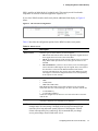
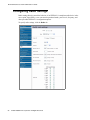
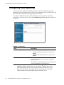
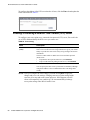
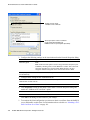
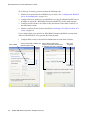
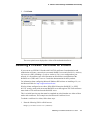
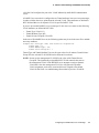
Using the Web UI to Configure 802.1X Authentication Information
To configure the Unified Access Point 802.1X supplicant user name and password by using
the Web interface, click the Authentication tab and configure the fields shown in Table 9.
Figure 6. IEEE 802.1X Authentication
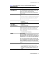
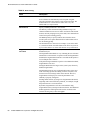
Table 9. IEEE 802.1X Supplicant Authentication
Field
Description
802.1X Supplicant
Click Enabled to enable the Administrative status of the 802.1X
Supplicant
Click Disabled to disable the Administrative status of the 802.1X
Supplicant.
Username
Enter the user name for the AP to use when responding to requests from
an 802.1X authenticator.
Password
Enter the password for the AP to use when responding to requests from
an 802.1X authenticator.
NOTE: After you configure the settings on the Authentication page, you must click
Update to apply the changes and to save the settings. Changing some access
point settings might cause the AP to stop and restart system processes. If this
happens, wireless clients will temporarily lose connectivity. We recommend
that you change access point settings when WLAN traffic is low.
Configuring IEEE 802.1X Authentication
35
D-Link Unified Access Point Administrator’s Guide
Using the CLI to Configure 802.1X Authentication Information
Table 10 shows the commands you can use to configure 802.1X supplicant information by
using the CLI.
Table 10. CLI Commands for the 802.1X Supplicant
Action
Command
View 802.1X supplicant settings
get dot1x-supplicant
Enable 802.1X supplicant
set dot1x-supplicant status up
Disable 802.1X supplicant
set dot1x-supplicant status down
Set the 802.1X user name
set dot1x-supplicant user <name>
Set the 802.1X password
set dot1x-supplicant password <password>
In the following example, the administrator enables the 802.1X supplicant and sets the user
name to wlanAP and the password to test1234.
DLINK-WLAN-AP# set
DLINK-WLAN-AP# set
DLINK-WLAN-AP# set
DLINK-WLAN-AP# get
Property Value
---------------status
up
user
wlanAP
dot1x-supplicant status up
dot1x-supplicant user wlanAP
dot1x-supplicant password test1234
dot1x-supplicant
Verifying the Installation
Make sure the access point is connected to the LAN and associate some wireless clients with
the network. Once you have tested the basics of your wireless network, you can enable more
security and fine-tune the AP by modifying advanced configuration features.
1. Connect the access point to the LAN
If you configured the access point and administrator PC by connecting both into a network
hub, then your access point is already connected to the LAN. The next step is to test some
wireless clients.
If you configured the access point by using a direct cable connection from your computer
to the access point, do the following procedures:
A. Disconnect the cable from the computer and the access point.
B. Connect an Ethernet cable from the access point to the LAN.
C. Connect your computer to the LAN by using an Ethernet cable or a wireless card.
2. Test LAN connectivity with wireless clients.
Test the access point by trying to detect it and associate with it from some wireless client
devices. For information about requirements for these clients, see “Wireless Client
Requirements” on page 22 in the Preparing to Install the Access Point chapter.
3. Secure and configure the access point by using advanced features.
36
© 2001-2008 D-Link Corporation. All Rights Reserved.
3 Installing the Access Point
Once the wireless network is up and you can connect to the AP with some wireless clients,
you can add in layers of security, create multiple virtual access points (VAPs), and
configure performance settings.
NOTE: The Unified Access Point is not designed for multiple, simultaneous
configuration changes. If more than one administrator is logged on to the
Administration Web pages and making changes to the configuration, there is
no guarantee that all configuration changes specified by multiple users will
be applied.
By default, no security is in place on the access point, so any wireless client can associate with
it and access your LAN. An important next step is to configure security, as described in
“Configuring Virtual Access Point Security” on page 43.
Verifying the Installation
37
D-Link Unified Access Point Administrator’s Guide
38
© 2001-2008 D-Link Corporation. All Rights Reserved.
4
Configuring Access Point Security
This chapter describes DWL-3500AP and DWL-8500AP security options and how to
configure security on the virtual access points (VAPs) to prevent unauthorized and
unauthenticated clients from accessing the WLAN. This chapter contains the following
sections:
•
•
Understanding Security on Wireless Networks
- Choosing a Security Mode
- Comparing Security Modes
- Enabling Station Isolation
Configuring Virtual Access Point Security
- Static WEP
- IEEE 802.1X
- WPA Personal
- WPA Enterprise
- Prohibiting the SSID Broadcast
Understanding Security on Wireless Networks
The DWL-3500AP and DWL-8500AP access points provide several authentication and
encryption schemes to ensure that your wireless infrastructure is accessed only by the intended
users. The details of each security mode are described in the following sections.
Some of the security modes use an external RADIUS server for client authentication. For
information about configuring an external RADIUS server, see “Wireless Client Settings and
RADIUS Server Setup” on page 101.
Choosing a Security Mode
In general, D-Link recommends that you use the most robust security mode that is feasible on
your network. When configuring security on the access point, you first must choose the
security mode, then in some modes you select an authentication algorithm and whether to
allow clients not using the specified security mode to associate.
Wi-Fi Protected Access (WPA) Enterprise with Remote Authentication Dial-In User Service
(RADIUS) using the Advanced Encryption Standard (AES) encryption algorithm using
Counter Mode with Cipher Block Chaining Message Authentication Code Protocol (CCMP)
Understanding Security on Wireless Networks
39
D-Link Unified Access Point Administrator’s Guide
provides the best data protection available and is the best choice if all client stations are
equipped with WPA supplicants. To use WPA Enterprise, you must have an external RADIUS
server on your network. Additionally, backward compatibility or interoperability issues with
clients or even with other access points may require that you configure WPA with RADIUS
with a different encryption algorithm or choose one of the other security modes.
For some networks, security might not be a priority. If you are simply providing Internet and
printer access, as on a guest network, setting the security mode to “None (Plain-text)” might
be the appropriate choice. To prevent clients from accidentally discovering and connecting to
your network, you can disable the broadcast SSID so that your network name is not advertised.
If the network is sufficiently isolated from access to sensitive information, this might offer
enough protection in some situations. For more information, see “Prohibiting the SSID
Broadcast” on page 53.
Comparing Security Modes
There are three major factors that determine the effectiveness of a security protocol:
•
•
•
How the protocol manages keys
What kind of encryption algorithm or formula the protocol uses to encode and decode the
data
Whether the protocol has integrated user authentication
The following sections describe the security modes available on the DWL-3500AP and DWL8500AP along with a description of the key management, authentication, and encryption
algorithms used in each mode.
•
•
•
•
•
When to Use Unencrypted (No Security)
When to Use Static WEP
When to Use IEEE 802.1X
When to Use WPA Personal
When to Use WPA Enterprise
This guide also includes some suggestions as to when one mode might be more appropriate
than another.
When to Use Unencrypted (No Security)
Setting the security mode to “None (Plain-text)” by definition provides no security. In this
mode, the data is not encrypted but rather sent as “plain text” across the network. No key
management, data encryption, or user authentication is used.
Recommendations
Unencrypted mode, i.e. None (Plain-text), is not recommended for networks with sensitive or
private information because it is not secure. Therefore, only set the security mode to “None
(Plain-text)” on the internal network for initial setup, testing, or problem solving.
When to Use Static WEP
Static Wired Equivalent Privacy (WEP) is a data encryption protocol for 802.11 wireless
networks. All wireless stations and access points on the network are configured with a static
40
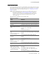
© 2001-2008 D-Link Corporation. All Rights Reserved.
4 Configuring Access Point Security
64-bit (40-bit secret key + 24-bit initialization vector (IV)), 128-bit (104-bit secret key + 24bit IV), or 152-bit (128-bit secret key + 24-bit IV) Shared Key for data encryption.
Key Management
Encryption Algorithm
User Authentication
Static WEP uses a fixed key
that is provided by the
administrator. WEP keys are
indexed in different slots (up to
four on the access point).
An RC4 stream cipher is used
to encrypt the frame body and
cyclic redundancy checking
(CRC) of each 802.11 frame.
This protocol provides a
rudimentary form of user
authentication when the client
uses a shared key algorithm.
The client stations must have
the same key indexed in the
same slot to access data on the
access point.
Recommendations
Static WEP was designed to provide the security equivalent of sending unencrypted data
through an Ethernet connection; however, it has major flaws and does not provide the intended
level of security.
Therefore, Static WEP is not recommended as a secure mode. The only time to use Static
WEP is when interoperability issues make it the only option available to you, and you are not
concerned with the potential of exposing the data on your network.
When to Use IEEE 802.1X
IEEE 802.1X is the standard for passing the Extensible Authentication Protocol (EAP) over an
802.11 wireless network using a protocol called EAP Encapsulation Over LANs (EAPOL).
This is a newer, more secure standard than Static WEP.
Key Management
Encryption Algorithm
User Authentication
IEEE 802.1X provides
dynamically-generated keys
that are periodically refreshed.
An RC4 stream cipher is used
to encrypt the frame body and
cyclic redundancy checking
(CRC) of each 802.11 frame.
IEEE 802.1X mode supports a
variety of authentication
methods, like certificates,
Kerberos, and public key
authentication with a RADIUS
server.
There are different Unicast
keys for each station.
Recommendations
IEEE 802.1X mode is a better choice than Static WEP because keys are dynamically generated
and changed periodically. However, the encryption algorithm used is the same as that of Static
WEP and is therefore not as reliable as the more advanced encryption methods such as
Temporal Key Integrity Protocol (TKIP) and AES-CCMP used in Wi-Fi Protected Access
(WPA) or WPA2.
Additionally, compatibility issues may be cumbersome because of the variety of
authentication methods supported and the lack of a standard implementation method.
Therefore, IEEE 802.1X mode is not as secure a solution as WPA or WPA2. A better solution
than using IEEE 802.1X mode is to use WPA Enterprise mode.
Understanding Security on Wireless Networks
41
D-Link Unified Access Point Administrator’s Guide
When to Use WPA Personal
Wi-Fi Protected Access Personal Pre-Shared Key (PSK) is an implementation of the Wi-Fi
Alliance IEEE 802.11i standard, which includes AES-CCMP and TKIP mechanisms. This
mode offers the same encryption algorithms as WPA 2 with RADIUS but without the ability to
integrate a RADIUS server for user authentication.
This security mode is backwards-compatible for wireless clients that support only the original
WPA.
Key Management
Encryption Algorithms
User Authentication
WPA Personal provides
dynamically-generated keys
that are periodically refreshed.
TKIP
The use of a PSK provides user
authentication similar to that of
shared keys in WEP.
AES-CCMP
There are different Unicast
keys for each station.
Recommendations
WPA Personal is not recommended for use with the Unified Access Point when WPA
Enterprise is an option.
We recommend that you use WPA Enterprise mode instead, unless you have interoperability
issues that prevent you from using this mode. For example, some devices on your network
might not support WPA or WPA2 with EAP talking to a RADIUS server. Embedded printer
servers or other small client devices with very limited space for implementation might not
support RADIUS. For such cases, we recommend that you use WPA Personal.
When to Use WPA Enterprise
Wi-Fi Protected Access Enterprise with RADIUS is an implementation of the Wi-Fi Alliance
IEEE 802.11i standard, which includes AES-CCMP and TKIP mechanisms. This mode
requires the use of a RADIUS server to authenticate users. On the Unified Access Point, WPA
Enterprise provides the best security available for wireless networks.
This security mode also provides backwards-compatibility for wireless clients that support
only the original WPA.
Key Management
Encryption Algorithms
User Authentication
WPA Enterprise mode provides
dynamically-generated keys
that are periodically refreshed.
TKIP
RADIUS
AES-CCMP
There are different Unicast
keys for each station.
Recommendations
WPA Enterprise mode is the recommended mode. The AES-CCMP and TKIP encryption
algorithms used with WPA modes are far superior to the RC4 algorithm used for Static WEP
or IEEE 802.1X modes. Therefore, AES-CCMP or TKIP should be used whenever possible.
All WPA modes allow you to use these encryption schemes, so WPA security modes are
recommended above the other modes when using WPA is an option.
42
© 2001-2008 D-Link Corporation. All Rights Reserved.
4 Configuring Access Point Security
Additionally, this mode incorporates a RADIUS server for user authentication which makes
WPA Enterprise more secure than WPA Personal mode.
Use the following guidelines for choosing options within the WPA Enterprise mode security
mode:
1. Currently, the best security you can have on a wireless network is WPA Enterprise mode
using AES-CCMP encryption algorithm. AES is a symmetric 128-bit block data
encryption technique that works on multiple layers of the network. It is the most effective
encryption system currently available for wireless networks. If all clients or other APs on
the network are WPA/CCMP compatible, use this encryption algorithm. (If all clients are
WPA2 compatible, choose to support only WPA2 clients.)
2. The second best choice is WPA Enterprise with the encryption algorithm set to both TKIP
and CCMP. This lets WPA client stations without CCMP associate, uses TKIP for
encrypting Multicast and Broadcast frames, and allows clients to select whether to use
CCMP or TKIP for Unicast (AP-to-single-station) frames. This WPA configuration allows
more interoperability, at the expense of some security. Client stations that support CCMP
can use it for their Unicast frames. If you encounter AP-to-station interoperability
problems with the “Both” encryption algorithm setting, then you will need to select TKIP
instead. (See next bullet.)
3. The third best choice is WPA Enterprise with the encryption algorithm set to TKIP. Some
clients have interoperability issues with CCMP and TKIP enabled at same time. If you
encounter this problem, then choose TKIP as the encryption algorithm. This is the
standard WPA mode and is usually interoperable with client Wireless software security
features.
Enabling Station Isolation
When Station Isolation is enabled, the access point blocks communication between wireless
clients associated with the same radio on the access point. The access point still allows data
traffic between its wireless clients and wired devices on the network, but not among wireless
clients. You enable station isolation on the Wireless settings page. For more information, see
“Setting the Wireless Interface” on page 55.
Configuring Virtual Access Point Security
You configure secure wireless client access by configuring security for each virtual access
point (VAP) that you enable. You can configure up to eight VAPs per radio that simulate
multiple APs in one physical access point. By default, only one VAP is enabled. For each VAP,
you can configure a unique security mode to control wireless client access.
VAPs segment the wireless LAN into multiple broadcast domains and are the wireless
equivalent of Ethernet VLANs. You can configure each VAP with a unique SSIDs so that each
VAP represents a different wireless network for clients to access. By configuring VAPs, you
can maintain better control over broadcast and multicast traffic, which affects network
performance.
Configuring Virtual Access Point Security
43
D-Link Unified Access Point Administrator’s Guide
This section describes the security options available for VAPs and how to configure VAP
security. For more information about configuring VAPs, including VLAN configuration, see
“Configuring Virtual Access Points” on page 62.
Each radio has eight VAPs, with VAP IDs from 0-7. By default, only VAP 0 on each radio is
enabled. VAP0 has the following default settings:
•
•
•
•
•
VLAN ID: 1
Broadcast SSID: Enabled
SSID: DLINK VAP
Security: None
MAC Authentication Type: None
All other VAPs are disabled by default. The default SSID for VAPs 1-7 is “Virtual Access
Point x” where x is the VAP ID.
To prevent unauthorized access to the Unified Access Point, we recommend that you select
and configure a security option other than None for the default VAP and for each VAP that you
enable.
To change VAP 0 or to enable and configure additional VAPs, select the VAP tab in the
Manage section.
Figure 7. Virtual Access Point Page.
VAP 0 through VAP 7 are listed in rows, and the column headings contain the configuration
options, which are described in “Configuring Virtual Access Points” on page 62. The dropdown menu in the Security column contains the following security mode options:
44
© 2001-2008 D-Link Corporation. All Rights Reserved.
4 Configuring Access Point Security
•
•
•
•
•
None
Static WEP
IEEE 802.1X
WPA Personal
WPA Enterprise
When you select a security mode other than None, additional fields appear. The following
sections describe how to configure each security mode.
None (Plain-text)
If you select None as your security mode, no further options are configurable on the AP. This
mode means that any data transferred to and from the access point is not encrypted. This
security mode can be useful during initial network configuration or for problem solving, but it
is not recommended for regular use on the internal network because it is not secure.
Static WEP
Static WEP is not the most secure mode available, but it offers more protection than setting the
security mode to None because it prevents an outsider from easily sniffing out unencrypted
wireless traffic. (For more secure modes, see the sections on “IEEE 802.1X” on page 49,
“WPA Personal” on page 50, or “WPA Enterprise” on page 52.)
WEP encrypts data moving across the wireless network based on a static key. (The encryption
algorithm is a “stream” cipher called RC4.)
If you select Static WEP as the Security Mode, additional fields display, as Figure 8 shows.
Figure 8. Static WEP Configuration
Configuring Virtual Access Point Security
45
D-Link Unified Access Point Administrator’s Guide
Table 11 describes the configuration options for static WEP.
Table 11. Static WEP
Field
Description
Transfer Key
Index
Select a key index from the drop-down menu. Key indexes 1 through 4 are
available. The default is 1.
The Transfer Key Index indicates which WEP key the access point will use
to encrypt the data it transmits.
Key Length
Specify the length of the key by clicking one of the radio buttons:
•
•
•
Key Type
Select the key type by clicking one of the radio buttons:
•
•
46
64 bits
128 bits
152 bits
ASCII
Hex
© 2001-2008 D-Link Corporation. All Rights Reserved.
4 Configuring Access Point Security
Table 11. Static WEP
Field
Description
WEP Keys
You can specify up to four WEP keys. In each text box, enter a string of
characters for each key.
If you selected “ASCII”, enter any combination ASCII characters. If you
selected “HEX”, enter hexadecimal digits (any combination of 0-9 and a-f
or A-F).
Use the same number of characters for each key as specified in the
“Characters Required” field. These are the RC4 WEP keys shared with the
stations using the access point.
Each client station must be configured to use one of these same WEP keys in
the same slot as specified here on the AP. (See “Static WEP Rules” on
page 48.)
Characters Required: The number of characters you enter into the WEP
Key fields is determined by the Key length and Key type you select. For
example, if you use 128-bit ASCII keys, you must enter 26 characters in the
WEP key. The number of characters required updates automatically based on
how you set Key Length and Key Type.
Authentication
The authentication algorithm defines the method used to determine whether a
client station is allowed to associate with an access point when static WEP is
the security mode.
Specify the authentication algorithm you want to use by choosing one of the
following options:
• Open System
• Shared Key
Note: You can also select both the Open System and Shared Key check
boxes.
Open System authentication allows any client station to associate with the
access point whether that client station has the correct WEP key or not. This
algorithm is also used in plain text, IEEE 802.1X, and WPA modes. When
the authentication algorithm is set to “Open System,” any client can associate
with the access point.
Note that just because a client station is allowed to associate does not ensure
it can exchange traffic with an access point. A station must have the correct
WEP key to be able to successfully access and decrypt data from an access
point, and to transmit readable data to the access point.
Shared Key authentication requires the client station to have the correct
WEP key in order to associate with the access point. When the authentication
algorithm is set to “Shared Key,” a station with an incorrect WEP key will
not be able to associate with the access point.
Both Open System and Shared Key. When you select both authentication
algorithms, client stations configured to use WEP in shared key mode must
have a valid WEP key in order to associate with the access point. Also, client
stations configured to use WEP as an open system (shared key mode not
enabled) will be able to associate with the access point even if they do not
have the correct WEP key.
NOTE: After you configure the security settings, you must click Update to apply the
changes and to save the settings. Changing some access point settings might
Configuring Virtual Access Point Security
47
D-Link Unified Access Point Administrator’s Guide
cause the AP to stop and restart system processes. If this happens, wireless
clients will temporarily lose connectivity. We recommend that you change
access point settings when WLAN traffic is low.
Static WEP Rules
If you use Static WEP, the following rules apply:
•
•
•
•
•
•
All client stations must have the Wireless LAN (WLAN) security set to WEP and all
clients must have one of the WEP keys specified on the AP in order to de-code AP-tostation data transmissions.
The AP must have all keys used by clients for station-to-AP transmit so that it can de-code
the station transmissions.
The same key must occupy the same slot on all nodes (AP and clients). For example if the
AP defines abc123 key as WEP key 3, then the client stations must define that same string
as WEP key 3.
Client stations can use different keys to transmit data to the access point. (Or they can all
use the same key, but this is less secure because it means one station can decrypt the data
being sent by another.)
On some wireless client software, you can configure multiple WEP keys and define a
client station “transfer key index”, and then set the stations to encrypt the data they
transmit using different keys. This ensures that neighboring APs cannot decode each
other’s transmissions.
You cannot mix 64-bit, 128-bit, and 152-bit WEP keys between the access point and its
client stations.
Example of Using Static WEP
In this example, the administrator configures three WEP keys on the access point and sets the
Transfer Key Index to “3.” This means that the WEP key in slot “3” is the key the access point
uses to encrypt the data it sends.
Figure 9. Static WEP Example
The administrator must then set all wireless client stations to use WEP and provide each client
with one of the slot/key combinations defined on the AP.
48
© 2001-2008 D-Link Corporation. All Rights Reserved.
4 Configuring Access Point Security
For this example, the administrator sets WEP key 3 in the wireless network properties of a
Windows client.
Figure 10. Providing a Wireless Client with a WEP Key
Additional wireless clients also need to have one of the WEP keys defined on the AP. The
administrator can assign the same WEP key that the first client has, or the administrator can
give the second station a different WEP key (key 2, for example) so that the two stations
cannot decrypt each other’s transmissions.
IEEE 802.1X
IEEE 802.1X is the standard defining port-based authentication and infrastructure for doing
key management. Extensible Authentication Protocol (EAP) messages are sent over an IEEE
802.11 wireless network using a protocol called EAP Encapsulation Over LANs (EAPOL).
IEEE 802.1X provides dynamically-generated keys that are periodically refreshed. An RC4
stream cipher is used to encrypt the frame body and perform a cyclic redundancy check (CRC)
on each 802.11 frame.
This mode requires the use of an external RADIUS server to authenticate users. The access
point requires a RADIUS server capable of EAP, such as the Microsoft Internet
Authentication Server. To work with Windows clients, the authentication server must support
Protected EAP (PEAP) and MSCHAP V2.
You can use any of a variety of authentication methods that the IEEE 802.1X mode supports,
including certificates, Kerberos, and public key authentication. You must configure the client
stations to use the same authentication method the access point uses.
Configuring Virtual Access Point Security
49
D-Link Unified Access Point Administrator’s Guide
If you select IEEE 802.1X as the Security Mode, additional fields display, as Figure 11 shows.
Figure 11. IEEE 802.1X Configuration
Table 12 describes the configuration options for the IEEE 802.1X security mode.
Table 12. IEEE 802.1X
Field
Description
Use Global
RADIUS Server
Settings
By default each VAP uses the global RADIUS settings that you define for
the AP at the top of the VAP page.
•
•
RADIUS IP
To use the global RADIUS server settings, make sure the check box is
selected.
To use a separate RADIUS server for the VAP, clear the check box and
enter the RADIUS server IP address and key in the following fields.
If the Use Global RADIUS Server Settings check box is cleared, enter the
RADIUS IP in the text box.
The RADIUS IP is the IP address of the RADIUS server.
RADIUS Key
If the Use Global RADIUS Server Settings check box is cleared, enter the
RADIUS Key in the text box.
The RADIUS Key is the shared secret key for the RADIUS server. The text
you enter will be displayed as “*” characters to prevent others from seeing
the RADIUS key as you type.
You can use up to 63 standard alphanumeric and special characters. The key
is case sensitive, and you must configure the same key on the AP and on
your RADIUS server.
Enable RADIUS
accounting
If the Use Global RADIUS Server Settings check box is cleared, click the
Enable RADIUS accounting check box to track and measure the resources
a particular user has consumed, such as system time, amount of data
transmitted and received, and so on.
NOTE: After you configure the security settings, you must click Update to apply the
changes and to save the settings. Changing some access point settings might
cause the AP to stop and restart system processes. If this happens, wireless
clients will temporarily lose connectivity. We recommend that you change
access point settings when WLAN traffic is low.
WPA Personal
WPA Personal is an implementation of the IEEE 802.11i standard, which includes AESCCMP and TKIP mechanisms. The Personal version of WPA employs a pre-shared key (PSK)
instead of using IEEE 802.1X and EAP as is used in the Enterprise WPA security mode). The
50
© 2001-2008 D-Link Corporation. All Rights Reserved.
4 Configuring Access Point Security
PSK is used for an initial check of credentials only. This security mode is backwardscompatible for wireless clients that support the original WPA.
If you select WPA Personal as the Security Mode, additional fields display, as Figure 12
shows.
Figure 12. WPA Personal Configuration
Table 13 describes the configuration options for the WPA Personal security mode.
Table 13. WPA Personal
Field
Description
WPA Versions
Select the types of client stations you want to support:
•
•
•
Cipher Suites
WPA. If all client stations on the network support the original WPA but
none support the newer WPA2, then select WPA.
WPA2. If all client stations on the network support WPA2, we suggest
using WPA2 which provides the best security per the IEEE 802.11i
standard.
WPA and WPA2. If you have a mix of clients, some of which support
WPA2 and others which support only the original WPA, select both of
the check boxes. This lets both WPA and WPA2 client stations
associate and authenticate, but uses the more robust WPA2 for clients
who support it. This WPA configuration allows more interoperability,
at the expense of some security.
Select the cipher suite you want to use:
• TKIP
• CCMP (AES)
• TKIP and CCMP (AES)
Both TKIP and AES clients can associate with the access point. WPA
clients must have one of the following to be able to associate with the AP:
• A valid TKIP key
• A valid AES-CCMP key
Clients not configured to use WPA Personal will not be able to associate
with the AP.
Key
The pre-shared key is the shared secret key for WPA Personal. Enter a string
of at least 8 characters to a maximum of 63 characters.
NOTE: After you configure the security settings, you must click Update to apply the
changes and to save the settings. Changing some access point settings might
cause the AP to stop and restart system processes. If this happens, wireless
clients will temporarily lose connectivity. We recommend that you change
access point settings when WLAN traffic is low.
Configuring Virtual Access Point Security
51
D-Link Unified Access Point Administrator’s Guide
WPA Enterprise
WPA Enterprise with RADIUS is an implementation of the IEEE 802.11i standard, which
includes CCMP (AES) and TKIP mechanisms. The Enterprise mode requires the use of a
RADIUS server to authenticate users.
This security mode is backwards-compatible with wireless clients that support the original
WPA.
If you select WPA Enterprise as the Security Mode, additional fields display as Figure 13
shows.
Figure 13. WPA Enterprise Configuration
Table 14 describes the configuration options for the WPA Enterprise security mode.
Table 14. WPA Enterprise
Field
Description
WPA Versions
Select the types of client stations you want to support:
•
•
•
Enable
pre-authentication
WPA. If all client stations on the network support the original WPA
but none support the newer WPA2, then select WPA.
WPA2. If all client stations on the network support WPA2, we suggest
using WPA2 which provides the best security per the IEEE 802.11i
standard.
WPA and WPA2. If you have a mix of clients, some of which support
WPA2 and others which support only the original WPA, select both
WPA and WPA2. This lets both WPA and WPA2 client stations
associate and authenticate but uses the more robust WPA2 for clients
who support it. This WPA configuration allows more interoperability,
at the expense of some security.
If for WPA Versions you select only WPA2 or both WPA and WPA2, you
can enable pre-authentication for WPA2 clients.
Click Enable pre-authentication if you want WPA2 wireless clients to
send pre-authentication packets. The pre-authentication information will be
relayed from the access point the client is currently using to the target
access point. Enabling this feature can help speed up authentication for
roaming clients who connect to multiple access points.
This option does not apply if you selected “WPA” for WPA Versions
because the original WPA does not support this feature.
52
© 2001-2008 D-Link Corporation. All Rights Reserved.
4 Configuring Access Point Security
Table 14. WPA Enterprise
Field
Description
Cipher Suites
Select the cipher suite you want to use:
• TKIP
• CCMP (AES)
• TKIP and CCMP (AES)
By default both TKIP and CCMP are selected. When both TKIP and
CCMP are selected, client stations configured to use WPA with RADIUS
must have one of the following:
•
•
Use Global RADIUS
Server Settings
By default each VAP uses the global RADIUS settings that you define for
the AP at the top of the VAP page.
•
•
RADIUS IP
A valid TKIP RADIUS IP address and RADIUS Key
A valid CCMP (AES) IP address and RADIUS Key
To use the global RADIUS server settings, make sure the check box is
selected.
To use a separate RADIUS server for the VAP, clear the check box and
enter the RADIUS server IP address and key in the following fields.
If the Use Global RADIUS Server Settings check box is cleared, enter the
RADIUS IP in the text box.
The RADIUS IP is the IP address of the RADIUS server.
RADIUS Key
If the Use Global RADIUS Server Settings check box is cleared, enter the
RADIUS Key in the text box.
The RADIUS Key is the shared secret key for the RADIUS server. The text
you enter will be displayed as “*” characters to prevent others from seeing
the RADIUS key as you type.
You can use up to 63 standard alphanumeric and special characters. The
key is case sensitive, and you must configure the same key on the AP and
on your RADIUS server.
Enable RADIUS
accounting
If the Use Global RADIUS Server Settings check box is cleared, click the
Enable RADIUS accounting check box to track and measure the resources
a particular user has consumed, such as system time, amount of data
transmitted and received, and so on.
NOTE: After you configure the security settings, you must click Update to apply the
changes and to save the settings. Changing some access point settings might
cause the AP to stop and restart system processes. If this happens, wireless
clients will temporarily lose connectivity. We recommend that you change
access point settings when WLAN traffic is low.
Prohibiting the SSID Broadcast
The column to the left of the Security modes allows you to enable or disable the SSID
broadcast. You can suppress (prohibit) the SSID broadcast to discourage stations from
automatically discovering your access point. When the broadcast SSID of the AP is
suppressed, the network name is not displayed in the list of available networks on a client
station. Instead, the client must have the exact network name configured in the supplicant
before it is able to connect.
Configuring Virtual Access Point Security
53
D-Link Unified Access Point Administrator’s Guide
Disabling the broadcast SSID is sufficient to prevent clients from accidentally connecting to
your network, but it will not prevent even the simplest of attempts by a hacker to connect or
monitor unencrypted traffic.
Suppressing the SSID broadcast offers a very minimal level of protection on an otherwise
exposed network (such as a guest network) where the priority is making it easy for clients to
get a connection and where no sensitive information is available.
54
© 2001-2008 D-Link Corporation. All Rights Reserved.
5
Managing the Access Point
This chapter describes how to manage the Unified Access Point and contains the following
sections:
•
•
•
•
•
Setting the Wireless Interface
Configuring Radio Settings
Configuring Virtual Access Points
Controlling Access by MAC Authentication
Configuring Load Balancing
The configuration pages for the features in this chapter are located under the Manage heading
on the Administration Web UI.
Setting the Wireless Interface
Wireless settings describe aspects of the LAN related specifically to the radio device in the
access point (802.11 mode) and to the network interface to the access point (access point MAC
address).
To configure the wireless interface, click the Wireless Settings tab.
NOTE: Figure 14 shows the Wireless Settings page for the DWL-8500AP.
Figure 14. Wireless Interface Configuration
Setting the Wireless Interface
55
D-Link Unified Access Point Administrator’s Guide
NOTE: For the DWL-8500AP, radio interface settings apply to both Radio Interface
1 and Radio Interface 2.
Table 15 describes the fields and configuration options available on the Wireless Settings
page.
Table 15. Wireless Settings
Field
Description
802.11d Regulatory
Domain Support
Enabling support for IEEE 802.11d (World Mode) on the access point
causes the AP to broadcast its operational country code as a part of its
beacons and probe responses. This allows client stations to operate in any
country without reconfiguration.
•
•
IEEE 802.11h
Support
To enable 802.11d regulatory domain support, click Enabled.
To disable 802.11d regulatory domain support, click Disabled.
The Administration UI shows whether IEEE 802.11h regulatory domain
control is in effect on the AP. IEEE 802.11h cannot be modified. For more
information, see “Using the 802.11h Wireless Mode” on page 57.
IEEE 802.11h is a standard that provides two services required to satisfy
certain regulatory domains for the 5 GHz band. These two services are
Transmit Power Control (TPC) and Dynamic Frequency Selection (DFS).
Note: The 802.11h mode is automatically enabled if the AP is configured
to work in any country that requires 802.11h as a minimum standard.
Station Isolation
To enable station isolation, select the option directly beside it.
•
•
When Station Isolation is disabled, wireless clients can communicate
with one another normally by sending traffic through the access point.
When Station Isolation is enabled, the access point blocks
communication between wireless clients. The access point still allows
data traffic between its wireless clients and wired devices on the
network, but not among wireless clients.
Radio Interface
The mode following the radio interface defines the IEEE wireless
networking standard of the radio.
MAC Address
Indicates the Media Access Control (MAC) addresses for the interface.
For the DWL-8500AP, this page shows the MAC addresses for Radio
Interface One and Radio Interface Two.
A MAC address is a permanent, unique hardware address for any device
that represents an interface to the network. The MAC address is assigned
by the manufacturer. You cannot change the MAC address. It is provided
here for informational purposes as a unique identifier for an interface.
NOTE: After you configure the wireless settings, you must click Update to apply the
changes and to save the settings. Changing some access point settings might
cause the AP to stop and restart system processes. If this happens, wireless
clients will temporarily lose connectivity. We recommend that you change
access point settings when WLAN traffic is low.
56
© 2001-2008 D-Link Corporation. All Rights Reserved.
5 Managing the Access Point
Using the 802.11h Wireless Mode
There are a number of key points about the IEEE 802.11h standard:
•
•
•
802.11h only works for the 802.11a band. It is not required for 802.11b or 802.11g.
If you are operating in an 802.11h enabled domain, the AP attempts to use the channel you
assign. If the channel has been blocked by a previous radar detection, or if the AP detects
a radar on the channel, then the AP automatically selects a different channel.
When 802.11h is enabled, the initial bootup time increases by a minimum of sixty
seconds. This is the minimum time required to scan the selected channel for radar
interference.
Setting the Wireless Interface
57
D-Link Unified Access Point Administrator’s Guide
Configuring Radio Settings
Radio settings directly control the behavior of an IEEE 802.11-compliant radio device in the
access point. Specifically, a user can control operational mode, power level, frequency, and
other per-radio IEEE 802.11 configuration options.
To specify radio settings, click the Radio tab.
58
© 2001-2008 D-Link Corporation. All Rights Reserved.
5 Managing the Access Point
Table 16 describes the fields and configuration options for the Radio Settings page.
Table 16. Radio Settings
Field
Description
Radio
(DWL-8500AP only)
Select Radio 1 or Radio 2 to specify which radio to configure. The
rest of the settings on this tab apply to the radio you select in this
field. Be sure to configure settings for both radios.
Note: this field is not available on the DWL-3500AP because it
only has one radio.
Status (On/Off)
Specify whether you want the radio on or off by clicking On or
Off.
If you turn off a radio, the AP sends disassociation frames to all the
wireless clients it is currently supporting so that the radio can be
gracefully shutdown and the clients can start the association
process with other available APs.
Mode
(DWL-8500AP Radio 1 only)
The Mode defines the wireless network standard the radio uses.
Mode
(DWL-3500 and
DWL-8500AP Radio 2)
The Mode defines the wireless network standard the radio uses.
Super AG
Super AG is a radio mode that attempts to increases performance
through bursting and frame compression. Performance increases
when the AP communicates with Super AG-enabled clients.
However, with Super AG enabled, the access point transmissions
consume more bandwidth.
•
•
•
•
•
•
Channel
IEEE 802.11a
Dynamic Turbo 5 GHz
IEEE 802.11g
Dynamic Turbo 2.4 GHz
To enable Super AG, click Enabled.
To disable Super AG, click Disabled.
Select the channel.
The range of available channels is determined by the mode of the
radio interface and the country code setting. If you select Auto for
the channel setting, the access point scans available channels and
selects a channel where no traffic is detected.
The Channel defines the portion of the radio spectrum the radio
uses for transmitting and receiving. Each mode offers a number of
channels, depending on how the spectrum is licensed by national
and transnational authorities such as the Federal Communications
Commission (FCC) or the International Telecommunication Union
(ITU-R).
Antenna
Select the antenna use to receive and transmit wireless traffic:
•
•
•
Auto: Automatically select the best antenna to send and
receive traffic.
Primary: Use the primary antenna to send and receive traffic.
Secondary: Use the secondary antenna to send and receive
traffic.
Configuring Radio Settings
59
D-Link Unified Access Point Administrator’s Guide
Table 16. Radio Settings
Field
Description
Beacon Interval
Enter a value from 20 to 2000 milliseconds.
Beacon frames are transmitted by an access point at regular
intervals to announce the existence of the wireless network. The
default behavior is to send a beacon frame once every 100
milliseconds (or 10 per second).
DTIM Period
Specify a DTIM period from 1-255 beacons.
The Delivery Traffic Information Map (DTIM) message is an
element included in some Beacon frames. It indicates which client
stations, currently sleeping in low-power mode, have data buffered
on the access point awaiting pick-up.
The DTIM period you specify indicates how often the clients
served by this access point should check for buffered data still on
the AP awaiting pickup.
The measurement is in beacons. For example, if you set this field
to 1, clients will check for buffered data on the AP at every beacon.
If you set this field to 10, clients will check on every 10th beacon.
Fragmentation
Threshold
Specify a number between 256 and 2,346 to set the frame size
threshold in bytes.
The fragmentation threshold is a way of limiting the size of frames
transmitted over the network. If a packet exceeds the fragmentation
threshold, the fragmentation function is activated and the packet is
sent as multiple 802.11 frames.
If the packet being transmitted is equal to or less than the threshold,
fragmentation is not used.
Setting the threshold to the largest value (2,346 bytes) effectively
disables fragmentation.
Fragmentation involves more overhead both because of the extra
work of dividing up and reassembling of frames it requires, and
because it increases message traffic on the network. However,
fragmentation can help improve network performance and
reliability if properly configured.
Sending smaller frames (by using lower fragmentation threshold)
might help with some interference problems; for example, it might
help with microwave oven interference.
By default, fragmentation is off. We recommend not using
fragmentation unless you suspect radio interference. The additional
headers applied to each fragment increase the overhead on the
network and can greatly reduce throughput.
60
© 2001-2008 D-Link Corporation. All Rights Reserved.
5 Managing the Access Point
Table 16. Radio Settings
Field
Description
RTS Threshold
Specify an RTS Threshold value between 0 and 2347.
The RTS threshold specifies the packet size of the minimum packet
for which a request to send (RTS) frame will be sent. This helps
control traffic flow through the access point, especially one with a
lot of clients.
If you specify a low threshold value, RTS packets will be sent more
frequently. This will consume more bandwidth and reduce the
throughput of the packet.
On the other hand, sending more RTS packets can help the network
recover from interference or collisions which might occur on a
busy network, or on a network experiencing electromagnetic
interference.
Maximum Stations
Specify the maximum number of stations allowed to associate to
this radio at any one time.
You can enter a value between 0 and 256.
Transmit Power
Enter a percentage value for the transmit power level for this
access point.
The default value, which is 100%, can be more cost-efficient than a
lower percentage since it gives the access point a maximum
broadcast range and reduces the number of APs needed.
To increase capacity of the network, place APs closer together and
reduce the value of the transmit power. This helps reduce overlap
and interference among APs. A lower transmit power setting can
also keep your network more secure because weaker wireless
signals are less likely to propagate outside of the physical location
of your network.
Rate Sets
Check the transmission rate sets you want the access point to
support and the basic rate sets you want the access point to
advertise:
•
•
•
Rates are expressed in megabits per second.
Supported Rate Sets indicate rates that the access point
supports. You can check multiple rates (click an option to
select or de-select a rate). The AP will automatically choose
the most efficient rate based on factors like error rates and
distance of client stations from the AP.
Basic Rate Sets indicate rates that the access point will
advertise to the network for the purposes of setting up
communication with other APs and client stations on the
network. It is generally more efficient to have an AP broadcast
a subset of its supported rate sets.
For the DWL-8500AP, use the Radio Settings page to configure both Radio One and Radio
Two. The settings on the page apply only to the radio that you select from the Radio list. After
you configure settings for one of the radios, click Update and then select and configure the
other radio. Be sure to click Update to apply the second set of configuration settings for the
other radio.
Configuring Radio Settings
61
D-Link Unified Access Point Administrator’s Guide
NOTE: After you configure the radio settings, you must click Update to apply the
changes and to save the settings. Changing these access point settings might
cause the AP to stop and restart system processes. Additionally, changing the
Super AG setting will cause the AP to reset. If this happens, wireless clients
will temporarily lose connectivity. We recommend that you change access
point settings when WLAN traffic is low.
Configuring Virtual Access Points
You can configure virtual access points (VAPs) to segment the wireless LAN into multiple
broadcast domains that are the wireless equivalent of Ethernet VLANs. You can configure up
to eight VAPs on a radio. The VAPs simulate multiple APs in one physical access point.
For each VAP, you can customize the security mode to control wireless client access. Each
VAP can also have a unique SSID. Multiple SSIDs make a single access point look like two or
more access points to other systems on the network. By configuring VAPs, you can maintain
better control over broadcast and multicast traffic, which affects network performance.
You can configure each VAP to use a different VLAN, or you can configure multiple VAPs to
use the same VLAN. VAP0 is always enabled and is assigned to VLAN 1 by default.
For the DWL-8500AP, VAP0 is always enabled on both radios, and VAPs can use a VLAN
whether the VLAN is on the same radio or on a different radio.
The access point adds VLAN ID tags to wireless client traffic based on the VLAN ID you
configure on the VAP page or by using the RADIUS server assignment. If you use an external
RADIUS server, you can configure multiple VLANs on each VAP. The external RADIUS
server assigns wireless clients to the VLAN when the clients associate and authenticate. For
more information about using a RADIUS server to manage VLANs, see “Configuring the
RADIUS Server for VLAN Tags” on page 122.
If wireless clients use a security mode that does not communicate with the RAIDUS server, or
if the RADIUS server does not provide the VLAN information, you can assign a VLAN ID to
each VAP. If the wireless client is not assigned a VLAN through any other method, the AP
assigns the VLAN ID specified in the VAP to all wireless clients that connect to the AP
through that VAP.
NOTE: Before you configure VLANs on the AP, be sure to verify that the switch and
DHCP server the Unified Access Point uses can support IEEE 802.1Q
VLAN encapsulation.
62
© 2001-2008 D-Link Corporation. All Rights Reserved.
5 Managing the Access Point
To set up multiple virtual access points, Click the VAP tab.
Table 17 describes the fields and configuration options on the VAP page.
Table 17. VAP Configuration
Field
Description
RADIUS IP
By default each VAP uses the global RADIUS settings that you define
for the AP at the top of the VAP page.
Enter the IP address of the RADIUS server on your network that all
VAPs use by default.
The RADIUS IP is the IP address of the global RADIUS server.
RADIUS Key
Enter the RADIUS Key in the text box.
The RADIUS Key is the shared secret key for the global RADIUS server.
The text you enter will be displayed as “*” characters to prevent others
from seeing the RADIUS key as you type.
Enable RADIUS
Accounting
Click this option if you want to log accounting information for clients
with user names and passwords.
Radio
(DWL-8500AP only)
Select the radio to configure. VAPs are configured independently on
each radio.
VAP
You can configure up to 8 VAPs on a radio. VAP0 is the physical radio
interface, so to disable VAP0, you must disable the radio.
Configuring Virtual Access Points
63
D-Link Unified Access Point Administrator’s Guide
Table 17. VAP Configuration
Field
Description
Enabled
You can enable or disable a configured network.
•
•
To enable the specified network, click the Enabled option beside
the appropriate VAP.
To disable the specified network, clear the Enabled option beside
the appropriate VAP.
If you disable the specified network, you will lose the VLAN ID you
entered.
VLAN ID
When a wireless client connects to the AP by using this VAP, the AP tags
all traffic from the wireless client with the VLAN ID you enter in this
field unless you enter the untagged VLAN ID or use a RADIUS server to
assign a wireless client to a VLAN. The range for the VLAN ID is 14094.
If you use RADIUS-based authentication for clients, you can optionally
add the following attributes to configure a VLAN for the client:
•
•
•
“Tunnel-Type”
“Tunnel-Medium-Type”
“Tunnel-Private-Group-ID”
The RADIUS-assigned VLAN ID overrides the VLAN ID you configure
on the VAP page.
Note: Any RADIUS-assigned VLAN cannot be the same as the
management VLAN.
You configure the untagged and management VLAN IDs on the Ethernet
Settings page. For more information, see ““Configuring the Ethernet
Interface” on page 31.
SSID
Enter a name for the wireless network. The SSID is an alphanumeric
string of up to 32 characters. You can use the same SSID for multiple
VAPs, or you can choose a unique SSID for each VAP.
Note: If you are connected as a wireless client to the same AP that you
are administering, resetting the SSID will cause you to lose connectivity
to the AP. You will need to reconnect to the new SSID after you save this
new setting.
Broadcast SSID
To enable the SSID broadcast, click the Broadcast SSID option.
By default, the access point broadcasts (allows) the Service Set Identifier
(SSID) in its beacon frames.
For information about turing off the SSID broadcast, see “Prohibiting the
SSID Broadcast” on page 53.
64
© 2001-2008 D-Link Corporation. All Rights Reserved.
5 Managing the Access Point
Table 17. VAP Configuration
Field
Description
Security
Select one of the following Security modes for this VAP:
•
•
•
•
•
None
Static WEP
WPA Personal
IEEE 802.1X
WPA Enterprise
If you select a security mode other than None, additional fields appear.
Note: The Security mode you set here is specifically for this Virtual
Access Point. For more information about the security options, see
“Configuring Virtual Access Point Security” on page 43.
MAC Authentication
Type
You can configure a global list of MAC addresses that are allowed or
denied access to the network. The menu for this feature allows you to
select the type of MAC Authentication to use:
•
•
•
Disabled—Do not use MAC Authentication.
Local—Use the MAC Authentication list that you configure on the
MAC Authentication page.
RADIUS—Use the MAC Authentication list on the external
RADIUS server.
For more information about MAC Authentication, see “Controlling
Access by MAC Authentication” on page 66.
NOTE: After you configure the VAP settings, you must click Update to apply the
changes and to save the settings. Changing some access point settings might
cause the AP to stop and restart system processes. If this happens, wireless
clients will temporarily lose connectivity. We recommend that you change
access point settings when WLAN traffic is low.
Configuring Virtual Access Points
65
D-Link Unified Access Point Administrator’s Guide
Controlling Access by MAC Authentication
A Media Access Control (MAC) address is a hardware address that uniquely identifies each
node of a network. All IEEE 802 network devices share a common 48-bit MAC address
format, usually displayed as a string of 12 hexadecimal digits separated by colons, for example
00:DC:BA:09:87:65. Each wireless network interface card (NIC) used by a wireless client has
a unique MAC address.
You can use the Administrator UI on the access point or use an external RADIUS server to
control access based on the MAC address of the wireless client. This feature is called MAC
Authentication or MAC Filtering. To control access locally, you configure a global list of
MAC addresses that are allowed or denied access to the network. To use the RADIUS server,
you configure authentication based on the MAC address of the client. When a wireless client
attempts to associate with an AP, the AP looks up the client’s MAC address on the RADIUS
server. If it is found, the global “allow” or “deny” setting is applied. If it is not found, the
opposite is applied.
You choose whether to use local or RADIUS-based MAC Authentication, local MAC
Authentication, or no MAC Authentication on the VAP page. For more information, see
“Configuring Virtual Access Points” on page 62.
Configuring a MAC Filter List on the AP
The MAC Authentication page allows you to control access to the access point based on
MAC addresses. Based on how you set the filter, you can allow only client stations with a
listed MAC address or deny access to the stations listed.
When you enable MAC Authentication and specify a list of approved MAC addresses, only
clients with a listed MAC address can access the network. If you specify MAC addresses to
deny, all clients can access the network except for the clients on the deny list.
To enable filtering by MAC address, click the MAC Authentication tab.
NOTE: Global MAC Authentication settings apply to all VAPs. For the
DWL-8500AP, the settings apply to all VAPs on both radios.
66
© 2001-2008 D-Link Corporation. All Rights Reserved.
5 Managing the Access Point
Table 18 describes the fields and configuration options available on the MAC Authentication
page.
Table 18. MAC Authentication
Field
Description
Filter
To set the MAC Address Filter, click one of the following buttons:
•
•
Allow only stations in the list
Block all stations in list
This setting applies to both RADIUS and local MAC authentication.
Stations List
To add a MAC Address to Stations List, enter its 48-bit MAC address
into the lower text boxes, then click Add.
The MAC Address is added to the Stations List.
To remove a MAC Address from the Stations List, select its 48-bit MAC
address, then click Remove.
The stations in the list will either be allowed or denied AP access based
on how you set the Filter.
NOTE: After you configure the settings on the MAC Authentication page, you must
click Update to apply the changes and to save the settings. Changing some
access point settings might cause the AP to stop and restart system processes.
If this happens, wireless clients will temporarily lose connectivity. We
recommend that you change access point settings when WLAN traffic is low.
Configuring MAC Authentication on the RADIUS Server
If you use RADIUS MAC authentication for MAC-based access control, you must configure
MAC entries in the RADIUS server, as described in Table 19.
Table 19. RADIUS Server Attributes for MAC Authentication
RADIUS Server
Attribute
Description
Value
User-Name (1)
MAC address of the client station.
Valid Ethernet MAC
Address.
User-Password (2)
A fixed global password used to lookup a
client MAC entry.
NOPASSWORD
Controlling Access by MAC Authentication
67
D-Link Unified Access Point Administrator’s Guide
Configuring Load Balancing
You can set network utilization thresholds on the access point to maintain the speed and
performance of the wireless network as clients associate and disassociate with the AP. For the
DWL-8500AP, the load balancing settings apply to both radios.
To configure load balancing and set limits and behavior to be triggered by a specified
utilization rate of the access point, click the Load Balancing tab and update the fields shown
in Table 20.
Table 20. Load Balancing
Field
Description
Load Balancing
Enable or disable load balancing:
•
•
Utilization for No New Associations
To enable load balancing on this access point, click
Enable.
To disable load balancing on this access point, click
Disable.
Provide the percentage of network bandwidth utilization
allowed on the radio before the AP stops accepting new
client associations.
The default is 0, which means that all new associations will
be allowed regardless of the utilization rate.
NOTE: After you configure the settings on the Load Balancing page, you must click
Update to apply the changes and to save the settings. Changing some access
point settings might cause the AP to stop and restart system processes. If this
happens, wireless clients will temporarily lose connectivity. We recommend
that you change access point settings when WLAN traffic is low.
68
© 2001-2008 D-Link Corporation. All Rights Reserved.
6
Configuring Access Point Services
This chapter describes how to configure services on the DWL-3500AP and DWL-8500AP and
contains the following sections:
•
•
Configuring Quality of Service (QoS)
Enabling the Network Time Protocol Server
Configuring Quality of Service (QoS)
Quality of Service (QoS) provides you with the ability to specify parameters on multiple
queues for increased throughput and better performance of differentiated wireless traffic like
Voice-over-IP (VoIP), other types of audio, video, and streaming media as well as traditional
IP data over the Unified Access Point.
Understanding QoS
A primary factor that affects QoS is network congestion due to an increased number of clients
attempting to access the air waves and higher traffic volume competing for bandwidth during a
busy time of day. The most noticeable degradation in service on a busy, overloaded network
will be evident in time-sensitive applications like Video, Voice-over-IP (VoIP), and streaming
media.
Unlike typical data files which are less affected by variability in QoS, Video, VoIP and
streaming media must be sent in a specific order at a consistent rate and with minimum delay
between packet transmission. If the quality of service is compromised, the audio or video will
be distorted.
QoS and Load Balancing
By using a combination of load balancing (see “Configuring Load Balancing” on page 68) and
QoS techniques, you can provide a high quality of service for time-sensitive applications even
on a busy network. Load balancing sets thresholds for client associations and AP utilization.
QoS is a means of allocating bandwidth and network access based on transmission priorities
for different types of wireless traffic within a single access point.
Configuring Quality of Service (QoS)
69
D-Link Unified Access Point Administrator’s Guide
802.11e and WMM Standards Support
QoS describes a range of technologies for controlling data streams on shared network
connections. The IEEE 802.11e task group is in the process of defining a QoS standard for
transmission quality and availability of service on wireless networks. QoS is designed to
provide better network service by minimizing network congestion; limiting Jitter, Latency,
and Packet Loss; supporting dedicated bandwidth for time-sensitive or mission critical
applications, and prioritizing wireless traffic for channel access.
As with all IEEE 802.11 working group standards, the goal is to provide a standard way of
implementing QoS features so that components from different companies are interoperable.
The Unified Access Point provides QoS based on the Wireless Multimedia (WMM)
specification, which implements a subset of 802.11e features.
Both access points and wireless clients (laptops, consumer electronics products) can be
WMM-enabled by the Wi-Fi Alliance.
QoS Queues and Parameters to Coordinate Traffic Flow
Configuring QoS options on the Unified Access Point consists of setting parameters on
existing queues for different types of wireless traffic. You can configure different minimum
and maximum wait times for the transmission of packets in each queue based on the
requirements of the media being sent. Queues automatically provide minimum transmission
delay for Voice, Video, multimedia, and mission critical applications, and rely on best-effort
parameters for traditional IP data.
For example, time-sensitive Voice, Video, and multimedia are given effectively higher priority
for transmission (lower wait times for channel access), while other applications and traditional
IP data which are less time-sensitive but often more data-intensive are expected to tolerate
longer wait times.
The Unified Access Point implements QoS based on the IEEE Wireless Multimedia (WMM)
standard. A Linux-based queuing class is used to tag packets and establish multiple queues.
The queues provided offer built-in prioritization and routing based on the type of data being
transmitted.
The Administration UI provides a way for you to configure parameters on the queues.
QoS Queues and Diff-Serve Code Points (DSCP) on Packets
QoS on the Unified Access Point leverages WMM information in the IP packet header related
to Diff-Serv Code Point (DSCP). Every IP packet sent over the network includes a DSCP field
in the header that indicates how the data should be prioritized and transmitted over the
network. The DSCP field consists of a 6 bit value defined by the local administration. For
WMM, the Wi-Fi Alliance suggests a particular mapping for DSCP values
The access point examines the DSCP field in the headers of all packets that pass through the
AP. Based on the value in a packet’s DSCP field, the AP prioritizes the packet for transmission
by assigning it to one of the queues. This process occurs automatically, regardless of whether
you deliberately configure QoS or not.
70
© 2001-2008 D-Link Corporation. All Rights Reserved.
6 Configuring Access Point Services
A different type of data is associated with each queue. The queue and associated priorities and
parameters for transmission are as follows:
•
•
•
•
Data 0 (Voice). Highest priority queue, minimum delay. Time-sensitive data such as Voice
over IP (VoIP) is automatically sent to this queue.
Data 1 (Video). High priority queue, minimum delay. Time-sensitive data such as Video
and other streaming media are automatically sent to this queue.
Data 2 (Best Effort). Medium priority queue, medium throughput and delay. Most
traditional IP data is sent to this queue.
Data 3 (Background). Lowest priority queue, high throughput. Bulk data that requires
maximum throughput and is not time-sensitive is sent to this queue (FTP data, for
example).
Using the QoS settings on the Administration UI, you can configure Enhanced Distributed
Channel Access (EDCA) parameters that determine how each queue is treated when it is sent
by the access point to the client or by the client to the access point.
Wireless traffic travels:
•
•
•
•
Downstream from the access point to the client station
Upstream from client station to access point
Upstream from access point to network
Downstream from network to access point
With WMM enabled, QoS settings on the Unified Access Point affect the first two of these;
downstream traffic flowing from the access point to client station (AP EDCA parameters) and
the upstream traffic flowing from the station to the access point (station EDCA parameters).
With WMM disabled, you can still set some parameters on the downstream traffic flowing
from the access point to the client station (AP EDCA parameters).
The other phases of the traffic flow (to and from the network) are not under control of the QoS
settings on the AP.
EDCF Control of Data Frames and Arbitration Interframe Spaces
Data is transmitted over 802.11 wireless networks in frames. A Frame consists of a discrete
portion of data along with some descriptive meta-information packaged for transmission on a
wireless network.
Each frame includes a source and destination MAC address, a control field with protocol
version, frame type, frame sequence number, frame body (with the actual information to be
transmitted) and frame check sequence for error detection.
The 802.11 standard defines various frame types for management and control of the wireless
infrastructure, and for data transmission. 802.11 frame types are (1) management frames, (2)
control frames, and (3) data frames. Management and control frames (which manage and
control the availability of the wireless infrastructure) automatically have higher priority for
transmission.
802.11e uses interframe spaces to regulate which frames get access to available channels and
to coordinate wait times for transmission of different types of data.
Configuring Quality of Service (QoS)
71
D-Link Unified Access Point Administrator’s Guide
Management and control frames wait a minimum amount of time for transmission; they wait a
short interframe space (SIF). These wait times are built-in to 802.11 as infrastructure support
and are not configurable.
The Unified Access Point supports the Enhanced Distribution Coordination Function (EDCF)
as defined by the 802.11e standard. EDCF, which is an enhancement to the DCF standard and
is based on CSMA/CA protocol, defines the interframe space (IFS) between data frames. Data
frames wait for an amount of time defined as the arbitration interframe space (AIFS) before
transmitting.
This parameter is configurable.
Random Backoff and Minimum / Maximum Contention Windows
If an access point detects that the medium is in use (busy), it uses the DCF random backoff
timer to determine the amount of time to wait before attempting to access a given channel
again. Each access point waits some random period of time between retries. The wait time
(initially a random value within a range specified as the Minimum Contention Window)
increases exponentially up to a specified limit (Maximum Contention Window). The random
delay avoids most of the collisions that would occur if multiple APs got access to the medium
at the same time and tried to transmit data simultaneously. The more active users you have on
a network, the more significant the performance gains of the backoff timer will be in reducing
the number of collisions and retransmissions.
Doubling continues on each try until MaxCW is reached
at which point this wait time is used on retries
until data is sent or until retries limit is reached
Backoff 4 = re-doubled
Backoff2 = MinCW doubled
Initial Backoff = random number in
range of MinCW
Backoff time
in milliseconds
1
5
10
15
20
25
The random backoff used by the access point is a configurable parameter. To describe the
random delay, a “Minimum Contention Window” (MinCW) and a “Maximum Contention
Window” (MaxCW) is defined.
•
•
72
The value specified for the Minimum Contention Window is the upper limit of a range for
the initial random backoff wait time. The number used in the random backoff is initially a
random number between 0 and the number defined for the Minimum Contention Window.
If the first random backoff time ends before successful transmission of the data frame, the
access point increments a retry counter, and doubles the value of the random backoff
window. The value specified in the Maximum Contention Window is the upper limit for
this doubling of the random backoff. This doubling continues until either the data frame is
sent or the Maximum Contention Window size is reached.
© 2001-2008 D-Link Corporation. All Rights Reserved.
6 Configuring Access Point Services
Packet Bursting for Better Performance
The Unified Access Point includes 802.11e based packet bursting technology that increases
data throughput and speed of transmission over the wireless network. Packet bursting enables
the transmission of multiple packets without the extra overhead of header information. The
effect of this is to increase network speed and data throughput. The size of packet bursts
allowed (maximum burst length) is a configurable parameter.
Transmission Opportunity (TXOP) Interval for Client Stations
The Transmission Opportunity (TXOP) is an interval of time when a Wi-Fi Multimedia
(WMM) client station has the right to initiate transmissions onto the wireless medium (WM).
802.1p and DSCP tags
IEEE 802.1p is an extension of the IEEE 802 standard and is responsible for QoS provision.
One purpose of 802.1p is to prioritize network traffic at the data link/ MAC layer.
The 802.1q tag includes a three-bit field for prioritization, which allows packets to be grouped
into various traffic classes. Eight priority levels are defined. The highest priority is seven,
which might go to network critical traffic (voice). The lowest priority level is zero, this is used
as a best-effort default, it is invoked automatically when no other value has been set.
NOTE: IEEE 802.1p prioritization will not work unless QoS and WMM are enabled.
WMM must be enabled on both the AP and on the client connecting to the
AP.
Configuring Quality of Service (QoS)
73
D-Link Unified Access Point Administrator’s Guide
Figure 15 outlines the way in which tags are retrieved and traffic prioritized on a network.
Figure 15. Traffic Prioritization
START
Is VLAN tag?
YES
NO
Take Priority from
DSCP
Is VLAN priority tag
(VLAN id = 0)
YES
NO
Is priority tag = 0
NO
Take priority from tag
Take priority from tag
YES
Take Priority from
DSCP
Table 21 outlines the VLAN priority and DSCP values.
Table 21. VLAN Priority Tags
74
VLAN Priority
Priority
0
Best Effort
0
1
Background
16
2
Background
8
3
Best Effort
24
4
Video
32
5
Video
40
6
Voice
48
7
Voice
56
© 2001-2008 D-Link Corporation. All Rights Reserved.
DSCP Value
6 Configuring Access Point Services
Configuring QoS Settings
Configuring Quality of Service (QoS) on the Unified Access Point consists of setting
parameters on existing queues for different types of wireless traffic, and effectively specifying
minimum and maximum wait times (through Contention Windows) for transmission. The
settings described here apply to data transmission behavior on the access point only, not to that
of the client stations.
AP Enhanced Distributed Channel Access (EDCA) Parameters affect traffic flowing from the
access point to the client station.
Station Enhanced Distributed Channel Access (EDCA) Parameters affect traffic flowing from
the client station to the access point.
The default values for the AP and station EDCA parameters are those suggested by the Wi-Fi
Alliance in the WMM specification. In normal use these values should not need to be changed.
Changing these values will affect the QoS provided.
NOTE: For the DWL-8500AP, the QoS settings apply to both radios but the traffic
for each radio is queued independently.
To set up queues for QoS, click the QoS tab under the Services heading and configure settings
as described in Table 22.
Configuring Quality of Service (QoS)
75
D-Link Unified Access Point Administrator’s Guide
Table 22. QoS Settings
Field
Description
AP EDCA Parameters
Queue
Queues are defined for different types of data transmitted from AP-tostation:
•
Data 0 (Voice)—High priority queue, minimum delay. Timesensitive data such as VoIP and streaming media are automatically
sent to this queue.
• Data 1(Video)—High priority queue, minimum delay. Timesensitive video data is automatically sent to this queue.
• Data 2 (best effort)—Medium priority queue, medium throughput
and delay. Most traditional IP data is sent to this queue.
• Data 3 (Background)—Lowest priority queue, high throughput.
Bulk data that requires maximum throughput and is not timesensitive is sent to this queue (FTP data, for example).
For more information, see “QoS Queues and Parameters to Coordinate
Traffic Flow” on page 70.
AIFS
(Inter-Frame Space)
The Arbitration Inter-Frame Spacing (AIFS) specifies a wait time (in
milliseconds) for data frames.
Valid values for AIFS are 1 through 255.
For more information, see “EDCF Control of Data Frames and
Arbitration Interframe Spaces” on page 71.
cwMin
(Minimum Contention
Window)
This parameter is input to the algorithm that determines the initial
random backoff wait time (“window”) for retry of a transmission.
The value specified for Minimum Contention Window is the upper limit
(in milliseconds) of a range from which the initial random backoff wait
time is determined.
The first random number generated will be a number between 0 and the
number specified here.
If the first random backoff wait time expires before the data frame is
sent, a retry counter is incremented and the random backoff value
(window) is doubled. Doubling will continue until the size of the
random backoff value reaches the number defined in the Maximum
Contention Window.
Valid values for cwMin are 1, 3, 7, 15, 31, 63, 127, 255, 511, or 1023.
The value for cwMin can be equal to or lower than the value for cwMax.
For more information, see “Random Backoff and Minimum / Maximum
Contention Windows” on page 72.
76
© 2001-2008 D-Link Corporation. All Rights Reserved.
6 Configuring Access Point Services
Table 22. QoS Settings
Field
Description
cwMax
(Maximum Contention
Window)
The value specified for the Maximum Contention Window is the upper
limit (in milliseconds) for the doubling of the random backoff value.
This doubling continues until either the data frame is sent or the
Maximum Contention Window size is reached.
Once the Maximum Contention Window size is reached, retries will
continue until a maximum number of retries allowed is reached.
Valid values for cwMax are 1, 3, 7, 15, 31, 63, 127, 255, 511, or 1023.
The value for cwMax can be equal to or higher than the value for
cwMin.
For more information, see “Random Backoff and Minimum / Maximum
Contention Windows” on page 72.
Max. Burst Length
The Max. Burst Length is an AP EDCA parameter and only applies to
traffic flowing from the access point to the client station.
This value specifies (in milliseconds) the maximum burst length
allowed for packet bursts on the wireless network. A packet burst is a
collection of multiple frames transmitted without header information.
The decreased overhead results in higher throughput and better
performance.
Valid values for maximum burst length are 0.0 through 999.
For more information, see “Packet Bursting for Better Performance” on
page 73.
Wi-Fi MultiMedia
Wi-Fi MultiMedia (WMM) is enabled by default. With WMM enabled,
QoS prioritization and coordination of wireless medium access is on.
With WMM enabled, QoS settings on the access point control
downstream traffic flowing from the access point to client station (AP
EDCA parameters) and the upstream traffic flowing from the station to
the access point (station EDCA parameters).
Disabling WMM deactivates QoS control of station EDCA parameters
on upstream traffic flowing from the station to the access point.
With WMM disabled, you can still set some parameters on the
downstream traffic flowing from the access point to the client station
(AP EDCA parameters).
•
•
To disable WMM extensions, click Disabled.
To enable WMM extensions, click Enabled.
Configuring Quality of Service (QoS)
77
D-Link Unified Access Point Administrator’s Guide
Table 22. QoS Settings
Field
Description
Station EDCA Parameters
Queue
Queues are defined for different types of data transmitted from stationto-AP:
•
Data 0 (Voice) - Highest priority queue, minimum delay. Timesensitive data such as VoIP and streaming media are automatically
sent to this queue.
• Data 1(Video) - Highest priority queue, minimum delay. Timesensitive video data is automatically sent to this queue.
• Data 2 (best effort) - Medium priority queue, medium throughput
and delay. Most traditional IP data is sent to this queue.
• Data 3 (Background) - Lowest priority queue, high throughput.
Bulk data that requires maximum throughput and is not timesensitive is sent to this queue (FTP data, for example).
For more information, see “QoS Queues and Parameters to Coordinate
Traffic Flow” on page 70.
AIFS
(Inter-Frame Space)
The Arbitration Inter-Frame Spacing (AIFS) specifies a wait time (in
milliseconds) for data frames.
Valid values for AIFS are 1 through 255.
For more information, see “EDCF Control of Data Frames and
Arbitration Interframe Spaces” on page 71.
cwMin
(Minimum Contention
Window)
This parameter is input to the algorithm that determines the initial
random backoff wait time (“window”) for retry of a transmission.
The value specified here in the Minimum Contention Window is the
upper limit (in milliseconds) of a range from which the initial random
backoff wait time is determined.
The first random number generated will be a number between 0 and the
number specified here.
If the first random backoff wait time expires before the data frame is
sent, a retry counter is incremented and the random backoff value
(window) is doubled. Doubling will continue until the size of the
random backoff value reaches the number defined in the Maximum
Contention Window.
Valid values for cwMin are 1, 3, 7, 15, 31, 63, 127, 255, 511, or 1023.
The value for cwMin can be equal to or lower than the value for cwMax.
For more information, see “Random Backoff and Minimum / Maximum
Contention Windows” on page 72.
78
© 2001-2008 D-Link Corporation. All Rights Reserved.
6 Configuring Access Point Services
Table 22. QoS Settings
Field
Description
cwMax
(Maximum Contention
Window)
The value specified here in the Maximum Contention Window is the
upper limit (in milliseconds) for the doubling of the random backoff
value. This doubling continues until either the data frame is sent or the
Maximum Contention Window size is reached.
Once the Maximum Contention Window size is reached, retries will
continue until a maximum number of retries allowed is reached.
Valid values for cwMax are 1, 3, 7, 15, 31, 63, 127, 255, 511, or 1023.
The value for cwMax can be equal to or higher than the value for
cwMin.
For more information, see “Random Backoff and Minimum / Maximum
Contention Windows” on page 72.
TXOP Limit
The TXOP Limit is a station EDCA parameter and only applies to
traffic flowing from the client station to the access point.
The Transmission Opportunity (TXOP) is an interval of time when a
WMM client station has the right to initiate transmissions onto the
wireless medium.
This value specifies the Transmission Opportunity (TXOP) for client
stations; that is, the interval of time when a WMM client station has the
right to initiate transmissions on the wireless network.
The TXOP Limit range is 0 to 65535. The value is in units of 32microsecond periods.
NOTE: After you configure the QoS settings, you must click Update to apply the
changes and to save the settings. Changing some access point settings might
cause the AP to stop and restart system processes. If this happens, wireless
clients will temporarily lose connectivity. We recommend that you change
access point settings when WLAN traffic is low.
Enabling the Network Time Protocol Server
The Network Time Protocol (NTP) is an Internet standard protocol that synchronizes
computer clock times on your network. NTP servers transmit Coordinated Universal Time
(UTC, also known as Greenwich Mean Time) to their client systems. NTP sends periodic time
requests to servers, using the returned time stamp to adjust its clock. The timestamp is used to
indicate the date and time of each event in log messages.
See http://www.ntp.org for more information about NTP.
Enabling the Network Time Protocol Server
79
D-Link Unified Access Point Administrator’s Guide
To configure the address of the NTP server that the AP uses, click the Time tab and update the
fields as described in Table 23.
Enabling or Disabling a Network Time Protocol (NTP) Server
To configure your access point to use a network time protocol (NTP) server, first enable the
use of NTP, and then identify the NTP server you want to use.
Table 23. SNTP Settings
Field
Description
Network Time Protocol
(NTP)
NTP provides a way for the access point to obtain and maintain its time
from a server on the network. Using an NTP server gives your AP the
ability to provide the correct time of day in log messages and session
information.
Choose to either enable or disable use of a network time protocol
(NTP) server:
•
•
NTP Server
To permit the AP to poll an NTP server, click Enabled.
To prevent the AP from polling an NTP server, click Disabled.
If NTP is enabled, select the NTP server you want to use.
You can specify the NTP server by host name or IP address, although
using the IP address is not recommended as these can change more
readily.
NOTE: After you configure the Time settings, you must click Update to apply the
changes and to save the settings. Changing some access point settings might
cause the AP to stop and restart system processes. If this happens, wireless
clients will temporarily lose connectivity. We recommend that you change
access point settings when WLAN traffic is low.
80
© 2001-2008 D-Link Corporation. All Rights Reserved.
7
Maintaining the Access Point
This chapter describes how to maintain the Unified Access Point and contains the following
sections:
•
•
Managing the Configuration File
Upgrading the Firmware
From the access point Administrator UI, you can perform the following maintenance tasks:
•
•
•
•
•
Restore the factory default configuration.
Create a backup of the running configuration file on to a management station.
Restore the AP configuration from a backup file.
Upgrade the firmware.
Reboot the AP.
Managing the Configuration File
The Unified Access Point configuration file is in XML format and contains all of the
information about the AP settings. You can download the configuration file to a management
station as a back-up copy or to manually edit the content. When you upload a configuration
file to the AP, the configuration information in the XML file is applied to the AP.
Managing the Configuration File
81
D-Link Unified Access Point Administrator’s Guide
Click the Configuration tab to access the configuration management page, which Figure 16
shows.
Figure 16. Configuration Management
The following sections describe the fields and options on the Configuration page.
Resetting the Factory Default Configuration
If you are experiencing problems with the Unified Access Point and have tried all other
troubleshooting measures, click Reset. This restores factory defaults and clears all settings,
including settings such as a new password or wireless settings. You can also use the reset
button on the back panel to reset the system to the default configuration. For information about
the reset button, see “Using the Reset Button” on page 23.
82
© 2001-2008 D-Link Corporation. All Rights Reserved.
7 Maintaining the Access Point
Saving the Current Configuration to a Backup File
You can use HTTP or TFTP to transfer files to and from the Unified Access Point. After you
download a configuration file to the management station, you can manually edit the file, which
is in XML format. Then, you can upload the edited configuration file to apply those
configuration settings to the AP.
Use the following steps to save a copy of the current settings on an access point to a backup
configuration file by using TFTP:
1. If it is not already selected, click the option for using TFTP to download the file.
2. Enter a name for the backup file in the Filename field, including the .xml file name
extension.
3. Enter the IP address of the TFTP server, including the path to the directory where you
want to save the file.
4. Click Download to save the file.
Use the following steps to save a copy of the current settings on an access point to a backup
configuration file by using HTTP:
1. Uncheck the Use TFTP to download the configuration box.
When you clear the option, the Filename and Server IP fields are disabled.
2. Click the Download button.
A File Download or Open dialog box displays.
3. From the dialog box, choose the Save option.
A file browser dialog box opens.
4. Use the file browser to navigate to the directory where you want to save the file, and click
OK to save the file.
You can keep the default file name (config.xml) or rename the backup file, but be sure to
save the file with an .xml extension.
Restoring the Configuration from a Previously Saved File
You can use HTTP or TFTP to transfer files to and from the Unified Access Point. After you
download a configuration file to the management station, you can manually edit the file, which
is in XML format. Then, you can upload the edited configuration file to apply those
configuration settings to the AP.
Managing the Configuration File
83
D-Link Unified Access Point Administrator’s Guide
Use the following procedures to restore the configuration on an access point to previously
saved settings by using TFTP:
1. If it is not already selected, click the option to use TFTP to upload the file.
2. Enter a name for the backup file in the Filename field, including the .xml file name
extension.
3. Enter the IP address of the TFTP server, including the path to the directory, that contains
the configuration file to upload.
4. Click the Restore button.
The AP reboots.
A “reboot” confirmation dialog and follow-on “rebooting” status message displays. Please
wait for the reboot process to complete, which might take several minutes.
The Administration Web UI is not accessible until the AP has rebooted.
Use the following steps to save a copy of the current settings on an access point to a backup
configuration file by using HTTP:
1. Uncheck the Use TFTP to upload the file box.
When you clear the option, the Server IP field is disabled.
2. Enter the name of the file to restore.
3. Click the Restore button.
A File Upload or Choose File dialog box displays.
4. Navigate to the directory that contains the file, then select the file to upload and click
Open.
(Only those files created with the Backup function and saved as .xml backup configuration
files are valid to use with Restore; for example, ap_config.xml.)
5. Click the Restore button.
The AP reboots.
A “reboot” confirmation dialog and follow-on “rebooting” status message displays. Please
wait for the reboot process to complete, which might take several minutes.
The Administration Web UI is not accessible until the AP has rebooted.
84
© 2001-2008 D-Link Corporation. All Rights Reserved.
7 Maintaining the Access Point
Rebooting the Access Point
For maintenance purposes or as a troubleshooting measure, you can reboot the Unified Access
Point. To reboot the access point, click the Reboot button on the Configuration page.
Upgrading the Firmware
As new versions of the DWL-3500AP and DWL-8500AP firmware become available, you can
upgrade the firmware on your devices to take advantages of new features and enhancements.
The AP uses a TFTP client for firmware upgrades. You can also use HTTP to perform
firmware upgrades.
NOTE: When you upgrade the firmware, the access point retains the existing
configuration information.
Use the following steps to upgrade the firmware on an access point by using TFTP:
1. Click the Upgrade tab in the Maintenance section.
Information about the current firmware version is displayed and an option to upgrade a
new firmware image is provided.
2. Make sure the Use TFTP to upload the file option is selected.
3. Enter a name for the image file in the New Firmware Image field, including the .tar file
name extension.
The firmware upgrade file supplied must be in the format <FileName>.upgrade.tar. Do
not attempt to use <FileName>.bin files or files of other formats for the upgrade; these
types of files will not work.
4. Enter the IP address of the TFTP server, including the path to the directory, that contains
the image to upload.
5. Click Upgrade.
Upon clicking Upgrade for the firmware upgrade, a popup confirmation window is
displayed that describes the upgrade process.
6. Click OK to confirm the upgrade and start the process.
Upgrading the Firmware
85
D-Link Unified Access Point Administrator’s Guide
NOTE: The firmware upgrade process begins once you click Upgrade and then OK
in the popup confirmation window.
The upgrade process may take several minutes during which time the access point will be
unavailable. Do not power down the access point while the upgrade is in process. When
the upgrade is complete, the access point restarts. The AP resumes normal operation with
the same configuration settings it had before the upgrade.
7. To verify that the firmware upgrade completed successfully, check the firmware version
shown on the Upgrade tab (and also on the Basic Settings tab). If the upgrade was
successful, the updated version name or number is indicated.
Use the following steps to upgrade the firmware on an access point by using HTTP:
1. Uncheck the Use TFTP to upload the file box.
When you clear the option, the Server IP field is disabled.
2. If you know the path to the New Firmware Image file, enter it in the New Firmware
Image textbox. Otherwise, click the Browse button and locate the firmware image file.
The firmware upgrade file supplied must be in the format <FileName>.tar. Do not
attempt to use <FileName>.bin files or files of other formats for the upgrade; these will
not work.
3. Click Upgrade to apply the new firmware image.
Upon clicking Upgrade for the firmware upgrade, a popup confirmation window is
displayed that describes the upgrade process.
4. Click OK to confirm the upgrade and start the process.
NOTE: The firmware upgrade process begins once you click Upgrade and then OK
in the popup confirmation window.
The upgrade process may take several minutes during which time the access point will be
unavailable. Do not power down the access point while the upgrade is in process. When
the upgrade is complete, the access point restarts. The AP resumes normal operation with
the same configuration settings it had before the upgrade.
5. To verify that the firmware upgrade completed successfully, check the firmware version
shown on the Upgrade tab (and also on the Basic Settings tab). If the upgrade was
successful, the updated version name or number is indicated.
86
© 2001-2008 D-Link Corporation. All Rights Reserved.
8
Configuring the Access Point for
Managed Mode
The Unified Access Point can operate in two modes: Standalone Mode or Managed Mode. In
Standalone Mode, the Unified Access Point acts as an individual access point in the network,
and you manage it by using the Administrator Web User Interface (UI) or the CLI. In Managed
Mode, the access point is part of the D-Link Unified Wired/Wireless Access System and you
manage it by using the D-Link Unified Switch. If an AP is in Managed Mode, the
Administrator Web UI, Telnet, and SSH services are disabled.
This chapter contains the following sections:
•
•
•
Transitioning Between Modes
Configuring Managed Access Point Settings
Viewing Managed AP DHCP Information
Transitioning Between Modes
Every 30 seconds, the D-Link Unified Switch sends a keepalive message to all of the access
points it manages. Each AP checks for the keepalive messages on the SSL TCP connection. As
long as the AP maintains communication with the switch through the keepalive messages, it
remains in Managed Mode.
If the AP does not receive a message within 45 seconds of the last keepalive message, the AP
assumes the switch has failed and terminates its TCP connection to the switch, and the AP
enters Standalone Mode.
Once the AP transitions to Standalone Mode, it continues to forward traffic without any loss.
The AP uses the configuration on the VAPs configured in VLAN Forwarding mode (the
standard, non-tunneled mode).
While the AP is in Standalone Mode, you can manage it by using the Web interface or the CLI
(through Telnet).
For any clients that are connected to the AP through tunneled VAPs, the AP sends disassociate
messages and disables the tunneled VAPs.
Transitioning Between Modes
87
D-Link Unified Access Point Administrator’s Guide
As long as the Managed AP Administrative Mode is set to Enabled, as Figure 17 shows, the
AP starts discovery procedures. If the AP establishes a connection with a wireless switch,
which may or may not be the same switch it was connected to before, the switch sends the AP
its configuration and the AP sends the wireless switch information about all currently
associated clients.
After the configuration from the switch is applied, the AP radios restart. Client traffic is briefly
interrupted until the radios are up and the clients are re-associated.
Configuring Managed Access Point Settings
On the Unified Access Point, you can configure the IP addresses of up to four D-Link Unified
Switches that can manage it. In order to manage the AP, the Unified Switch and AP must
discover each other. There are multiple ways for a Unified Switch to discover an AP. Adding
the IP address of the Unified Switch to the AP while it is in Standalone Mode is one way to
enable switch-to-AP discovery.
To add the IP address of a D-Link Unified Switch to the AP, click the Managed Access Point
tab under the Manage heading and update the fields shown in Table 24.
Figure 17. Managed Access Point Settings
Table 24. Managed Access Point
Field
Description
Managed AP
Administrative Mode
Click Enabled to allow the AP and Unified Switch to discover each
other. If the AP successfully authenticates itself with a Unified
Switch, you will not be able to access the Administrator UI.
Click Disabled to prevent the AP from contacting wireless switches.
88
© 2001-2008 D-Link Corporation. All Rights Reserved.
8 Configuring the Access Point for Managed Mode
Table 24. Managed Access Point
Field
Description
Switch IP address
Enter the IP address of up to four wireless switches that can manage
the AP. You can enter the IP address in dotted format or as an DNS
name.
You can view a list of wireless switches on your network that were
configured by using a DHCP server. For more information, see
“Configuring Managed Access Point Settings” on page 88.
The AP attempts to contact Switch IP Address 1 first.
Pass Phrase
Enter a pass phrase to allow the Access Point to authenticate itself
with the Unified Switch. The pass phrase can be up to 32
alphanumeric characters.
You must configure the same pass phrase on the Unified Switch.
NOTE: After you configure the settings on the Managed Access Point page, you
must click Update to apply the changes and to save the settings. Changing
some access point settings might cause the AP to stop and restart system
processes. If this happens, wireless clients will temporarily lose connectivity.
We recommend that you change access point settings when WLAN traffic is
low.
If the Unified Access Point successfully authenticates with a D-Link Unified Switch, you will
loose access to the AP through the Administrator UI.
Viewing Managed AP DHCP Information
The Unified Access Point can learn about D-Link Unified Switches on the network through
DHCP responses to its initial DHCP request. The Managed AP DHCP page displays the DNS
names or IP addresses of up to four D-Link Unified Switches that the AP learned about from a
DHCP server on your network.
For information about how to configure a DHCP server to respond to AP DHCP requests with
the Unified Switch IP address information, see the D-Link Unified Wired/Wireless Access
System User Manual.
Viewing Managed AP DHCP Information
89
D-Link Unified Access Point Administrator’s Guide
90
© 2001-2008 D-Link Corporation. All Rights Reserved.
9
Viewing Access Point Status
This chapter describes the information you can view from the tabs under the Status heading on
the Administration Web UI. This chapter contains the following sections:
•
•
•
•
•
Viewing Interface Status
Viewing Events Logs
Viewing Transmit and Receive Statistics
Viewing Client Association Information
Viewing Neighboring Access Points
Viewing Interface Status
To monitor Ethernet LAN and wireless LAN (WLAN) settings, click the Interfaces tab.
This page displays the current settings of the Unified Access Point. It displays the Wired
Settings and the Wireless Settings.
Viewing Interface Status
91
D-Link Unified Access Point Administrator’s Guide
Ethernet (Wired) Settings
The Internal interface includes the Ethernet MAC Address, Management VLAN ID, IP
Address, Subnet Mask, and DNS information. If you want to change any of these settings,
click the Edit link.
For information about configuring these settings, see “Configuring the Ethernet Interface” on
page 31.
Wireless Settings
The Radio Interface includes the Radio Mode and Channel. The Wireless Settings section
also shows the MAC address (read-only) associated with the radio interface.
If you want to change the Radio Mode or Channel settings, click the Edit link. For information
about configuring these settings, see “Setting the Wireless Interface” on page 55 and
“Configuring Radio Settings” on page 58.
Viewing Events Logs
The Events Log shows real-time system events on the access point such as wireless clients
associating with the AP and being authenticated.
To view system events, click the Events tab.
Figure 18. Viewing and Configuring System Events
From the Events page, you can view the most recent events generated by this access point and
configure logging settings. You can enable and configure persistent logging to write system
event logs to non-volatile memory so that the events are not erased when the system reboots.
This page also gives you the option of enabling a remote “log relay host” to capture all system
events and errors in a Kernel Log.
NOTE: The Unified Access Point acquires its date and time information using the
network time protocol (NTP). This data is reported in UTC format (also
known as Greenwich Mean Time). You need to convert the reported time to
92
© 2001-2008 D-Link Corporation. All Rights Reserved.
9 Viewing Access Point Status
your local time. For information on setting the network time protocol, see
“Enabling the Network Time Protocol Server” on page 79.
Configuring Persistent Logging Options
If the system unexpectedly reboots, log messages can be useful to diagnose the cause.
However, log messages are erased when the system reboots unless you enable persistent
logging.
CAUTION: Enabling persistent logging can wear out the non-volatile (flash) memory
and degrade network performance. You should only enable persistent
logging to debug a problem. Make sure you disable persistent logging
after you finish debugging the problem.
To configure persistent logging on the Events page, set the persistence, severity, and depth
options as described in Table 26, and then click Update.
Table 25. Logging Options
Field
Description
Persistence
Choose Enabled to save system logs to non-volatile memory so that the logs are
not erased when the AP reboots. Choose Disabled to save system logs to volatile
memory. Logs in volatile memory are deleted when the system reboots.
Severity
Specify the severity level of the log messages to write to non-volatile memory.
For example, if you specify 2, critical, alert, and emergency logs are written to
non-volatile memory. Error messages with a severity level of 3-7 are written to
volatile memory.
•
•
•
•
•
•
•
•
Depth
0—emergency
1—alert
2—critical
3—error
4—warning
5—notice
6—info
7—debug
You can store up to 128 messages in non-volatile memory. Once the number you
configure in this field is reached, the oldest log event is overwritten by the new
log event.
NOTE: To apply your changes, click Update. Changing some access point settings
might cause the AP to stop and restart system processes. If this happens,
wireless clients will temporarily lose connectivity. We recommend that you
change access point settings when WLAN traffic is low.
Viewing Events Logs
93
D-Link Unified Access Point Administrator’s Guide
Configuring the Log Relay Host for Kernel Messages
The Kernel Log is a comprehensive list of system events (shown in the System Log) and
kernel messages such as error conditions, like dropping frames.
You cannot view kernel log messages directly from the Administration Web UI for an access
point. You must first set up a remote server running a syslog process and acting as a syslog
“log relay host” on your network. Then, you can configure the Unified Access Point to send
syslog messages to the remote server.
Remote log server collection for access point syslog messages provides the following features:
•
•
•
Allows aggregation of syslog messages from multiple access points
Stores a longer history of messages than kept on a single access point
Triggers scripted management operations and alerts
To use Kernel Log relaying, you must configure a remote server to receive the syslog
messages. The procedure to configure a remote log host depends on the type of system you use
as the remote host. The following example describes how to configure a remote Linux server
using the syslog daemon.
Example of Using Linux syslogd
The following steps activate the syslog daemon on a Linux server. Make sure you have root
user identity for these tasks.
1. Log on as root to the machine you want to use as your syslog relay host.
The following operations require root user permissions. If you are not already logged on
as root, type su at the command line prompt to become root (“super user”).
2. Edit /etc/init.d/sysklogd and add “-r” to the variable SYSLOGD near the top of the
file. The line you edit will look like this:
SYSLOGD=“-r”
To view the Linux manual page to get more information about the SYSLOGD command
options, enter man syslogd at the command prompt.
3. To send all the messages to a file, edit /etc/syslog.conf.
For example you can add the following line to send all messages to a log file called
AP_syslog:
*.*
-/tmp/AP_syslog
To view the Linux manual page to get more information about the syslog.conf command
options, enter man syslogd at the command prompt.
4. Restart the syslog server by typing the following at the command line prompt:
/etc/init.d/sysklogd restart
NOTE: The syslog process will default to use port 514. We recommend keeping this
default port. However; If you choose to reconfigure the log port, make sure
that the port number you assign to syslog is not being used by another
process.
94
© 2001-2008 D-Link Corporation. All Rights Reserved.
9 Viewing Access Point Status
Enabling or Disabling the Log Relay Host on the Events Page
To enable and configure Log Relaying on the Events page, set the Log Relay options as
described in Table 26, and then click Update.
Table 26. Log Relay Host
Field
Description
Relay Log
Choose to either enable or disable use of the Log Relay Host.
If you select the Relay Log option, the Log Relay Host is enabled and the Relay
Host and Relay Port fields are editable.
Relay Host
Specify the IP Address or DNS name of the remote log server.
Relay Port
Specify the Port number for the syslog process on the Relay Host.
The default port is 514.
NOTE: To apply your changes, click Update. Changing some access point settings
might cause the AP to stop and restart system processes. If this happens,
wireless clients will temporarily lose connectivity. We recommend that you
change access point settings when WLAN traffic is low.
If you enabled the Log Relay Host, clicking Update will activate remote logging. The access
point will send its kernel messages real-time for display to the remote log server monitor, a
specified kernel log file, or other storage, depending on how you configured the Log Relay
Host.
If you disabled the Log Relay Host, clicking Update will disable remote logging.
Viewing Transmit and Receive Statistics
The Transmit/Receive page provides some basic information about the current access point
and a real-time display of the transmit and receive statistics for the Ethernet interface on the
access point and for all VAPs on the radio interface (and for both radio interfaces on the DWL8500AP). All transmit and receive statistics shown are totals since the access point was last
started. If you reboot the AP, these figures indicate transmit and receive totals since the reboot.
Viewing Transmit and Receive Statistics
95
D-Link Unified Access Point Administrator’s Guide
To view transmit and receive statistics for the access point, click the Transmit/Receive tab.
Table 27. Transmit/Receive Statistics
Field
Description
Interface
The name of the Ethernet or VAP interface.
Status
Shows whether the interface is up or down.
MAC Address
MAC address for the specified interface.
The access point has a unique MAC address for each
interface. For the DWL-8500AP, each radio has a
different MAC address for every interface on each of its
two radios.
VLAN ID
Virtual LAN (VLAN) ID.
You can use VLANs to establish multiple internal and
guest networks on the same access point.
The VLAN ID is set on the VAP tab. (See “Configuring
Virtual Access Points” on page 62.)
96
© 2001-2008 D-Link Corporation. All Rights Reserved.
9 Viewing Access Point Status
Table 27. Transmit/Receive Statistics
Field
Description
Name (SSID)
Wireless network name. Also known as the SSID, this
alphanumeric key uniquely identifies a wireless local
area network.
The SSID is set on the VAP tab. (See “Configuring
Virtual Access Points” on page 62.)
Transmit and Receive Information
Total Packets
Indicates total packets sent (in Transmit table) or
received (in Received table) by this access point.
Total Bytes
Indicates total bytes sent (in Transmit table) or received
(in Received table) by this access point.
Errors
Indicates total errors related to sending and receiving
data on this access point.
Viewing Client Association Information
To view the client stations associated with a particular access point, click the
Client Associations tab.
The associated stations are displayed along with information about packet traffic transmitted
and received for each station.
Table 28 describes the fields on the Client Associations page.
Table 28. Associated Clients
Field
Network
Description
Shows which virtual access point the client is associated with. For example,
an entry of wlan0vap2 means the client is associated with Radio 1, VAP 2.
An entry of wlan0 means the client is associated with VAP 0 on Radio 1. For
the DWL-8500AP, an entry of wlan1 means the client is associated with VAP
0 on Radio 2.
Station
Shows the MAC address of the associated wireless client.
Viewing Client Association Information
97
D-Link Unified Access Point Administrator’s Guide
Table 28. Associated Clients
Field
Status
Description
The “Authenticated” and “Associated” Status shows the underlying IEEE
802.11 authentication and association status, which is present no matter
which type of security the client uses to connect to the AP. This status does
not show IEEE 802.1X authentication or association status.
Some points to keep in mind with regard to this field are:
•
•
If the AP security mode is None or Static WEP, the authentication and
association status of clients showing on the Client Associations tab will
be in line with what is expected; that is, if a client shows as authenticated
to the AP, it will be able to transmit and receive data. (This is because
Static WEP uses only IEEE 802.11 authentication.)
If the AP uses IEEE 802.1X or WPA security, however, it is possible for
a client association to show on this tab as authenticated (via the IEEE
802.11 security) but actually not be authenticated to the AP via the
second layer of security.
From Station
Shows the number of packets and bytes received from the wireless client.
To Station
Shows the number of packets and bytes transmitted from the AP to the wireless client.
Link Integrity Monitoring
The Unified Access Point provides link integrity monitoring to continually verify its
connection to each associated client. To do this monitoring, the AP sends data packets to
clients every few seconds when no other traffic is passing. This allows the access point to
detect when a client goes out of range, even during periods when no normal traffic is
exchanged. The client connection drops off the list within 300 seconds if these data packets are
not acknowledged, even if no disassociation message is received.
Viewing Neighboring Access Points
The status page for Neighboring Access Points provides real-time statistics for all access
points within range of the access point on which you are viewing the Administration Web
pages.
To view information about other access points on the wireless network, click the
Neighboring Access Points tab.
You must enable the AP detection on the AP in order to collect information about other APs
within range.
98
© 2001-2008 D-Link Corporation. All Rights Reserved.
9 Viewing Access Point Status
Table 29 describes the information provided on neighboring access points.
Table 29. Neighboring Access Points
Field
Description
AP Detection
To enable neighbor access point detection and collect information about
neighbor APs, click Enabled.
To disable neighbor AP detection, click Disabled.
MAC Address
Shows the MAC address of the neighboring access point.
Radio
The Radio field indicates which radio detected the neighboring AP:
•
•
Beacon Interval
wlan0 (Radio 1)
wlan1 (Radio 2 - DWL-8500AP only)
Shows the Beacon interval being used by this access point.
Beacon frames are transmitted by an access point at regular intervals to
announce the existence of the wireless network. The default behavior is to
send a beacon frame once every 100 milliseconds (or 10 per second).
The Beacon Interval is set on the Radio tab page. (See “Configuring Radio
Settings” on page 58.)
Type
Indicates the type of device:
•
•
SSID
AP indicates the neighboring device is an access point that supports the
IEEE 802.11 Wireless Networking Framework in Infrastructure Mode.
Ad hoc indicates a neighboring station running in Ad hoc Mode. Stations
set to ad hoc mode communicate with each other directly, without the use
of a traditional access point. Ad-hoc mode is an IEEE 802.11 Wireless
Networking Framework also referred to as peer-to-peer mode or an
Independent Basic Service Set (IBSS).
The Service Set Identifier (SSID) for the access point.
The SSID is an alphanumeric string of up to 32 characters that uniquely
identifies a wireless local area network. It is also referred to as the Network
Name.
The SSID is set on the VAP tab. (See “Configuring Virtual Access Points” on
page 62.)
Privacy
Indicates whether there is any security on the neighboring device.
•
Off indicates that the Security mode on the neighboring device is set to
“None” (no security).
• On indicates that the neighboring device has some security in place.
Security is configured on the AP from the VAP page. For more information
about security settings, see “Configuring Access Point Security” on page 39.
WPA
Indicates whether WPA security is “on” or “off” for this access point.
Viewing Neighboring Access Points
99
D-Link Unified Access Point Administrator’s Guide
Table 29. Neighboring Access Points
Field
Description
Band
This indicates the IEEE 802.11 mode being used on the neighboring access
point. (For example, IEEE 802.11a or IEEE 802.11g.).
The number shown indicates the mode according to the following map:
•
•
•
Channel
2.4 indicates IEEE 802.11b mode, IEEE 802.11g mode, or 2.4 GHz
Dynamic Turbo
5 indicates IEEE 802.11a mode or 5 GHz Dynamic Turbo
5 Turbo indicates Turbo 5 GHz mode (this option displays only if your
AP and the neighbor AP are both configured for “Turbo 5 GHz” and are
operating in the same channel)
Shows the channel on which the access point is currently broadcasting.
The Channel defines the portion of the radio spectrum that the radio uses for
transmitting and receiving.
The channel is set in Radio Settings. (See “Configuring Radio Settings” on
page 58.)
Rate
Shows the rate (in megabits per second) at which this access point is currently
transmitting.
The current rate will always be one of the rates shown in Supported Rates.
Signal
Indicates the strength of the radio signal emitting from this access point as
measured in decibels (dB).
Beacons
Shows the total number of beacons received from this access point since it
was first discovered.
Last Beacon
Shows the date and time of the last beacon received from this access point.
Rates
Shows supported and basic (advertised) rate sets for the neighboring access
point. Rates are shown in megabits per second (Mbps).
All Supported Rates are listed, with Basic Rates shown in bold.
Rate sets are configured on the Radio Settings page. (See “Configuring Radio
Settings” on page 58.)
100
© 2001-2008 D-Link Corporation. All Rights Reserved.
A
Wireless Client Settings and RADIUS
Server Setup
Typically, users configure security on their wireless clients for access to many different
networks (access points). The list of available wireless networks changes depending on the
location of the client and which APs are online and detectable in that location.1 Once an AP
has been detected by the client and security is configured for it, it remains in the client’s list of
networks but shows as either reachable or unreachable depending on the situation. For each
network (AP) you want to connect to, configure security settings on the client to match the
security mode being used by that network.
The following sections describe how to set up each of the supported security modes on
wireless clients of a network served by the Unified Access Point:
•
•
•
•
•
•
•
•
•
•
Accessing Wireless Client Security Settings
Configuring a Client to Access an Unsecure Network
Configuring Static WEP Security on a Client
Configuring WPA/WPA2 Personal on a Client
Using an External Authentication Server
Configuring IEEE 802.1X Security on a Client
Configuring WPA/WPA2 Enterprise (RADIUS)
Configuring the RADIUS Server for Authentication
Obtaining a TLS-EAP Certificate for a Client
Configuring the RADIUS Server for VLAN Tags
NOTE: The recommended sequence for security configuration is (1) set up security
on the access point, and (2) configure security on each of the wireless clients.
A typical method to configure security is to connect to an access point that has no
security set (None) from an unsecure wireless client. With this initial connection, you
can access the Security page on the AP Administration Web UI and configure a
security mode.
When you re-configure the access point with a security setting and click Update, your
1. The exception to this is if the access point is set to prohibit the broadcast of its network name. In this case the
SSID will not show up in the list of Available Networks on the client. Instead, the client must have the exact network name configured in the network connection properties before it will be able to connect.
101
D-Link Unified Access Point Administrator’s Guide
wireless client will be disassociated and you will lose connectivity to the AP
Administration Web pages. In some cases, you may need to make additional changes
to the AP security settings before you configure the client. Therefore, you must have a
backup Ethernet (wired) connection.
This appendix describes security setup on a client that uses Microsoft Windows client software
for wireless connectivity. The Windows client software is used as the example because of its
widespread availability on Windows computers and laptops. These procedures will vary
slightly if you use different software on the client, but the configuration information you need
to provide is the same.
Before you start to configure wireless clients, make sure that the software on the wireless
clients is current. Software updates for wireless clients might include service packs, patches,
and new releases of drivers and other supporting technologies. A common problem
encountered in client security setup is not having the right driver or updates to it on the client.
Even many client cards currently available do not ship from the factory with the latest drivers.
Accessing Wireless Client Security Settings
The procedures in this section describe how to access the wireless security settings on a
Microsoft Windows XP system and might not apply to all wireless clients, even if they are
running Microsoft Windows. You can use the following procedures to access the security
settings dialogue:
1. Open the Wireless Network Connection Properties.
From the wireless connection icon on the Windows task bar:
-
Right-click on the Wireless connection icon in your Windows task bar and select View
available wireless networks.
Select the SSID of the network to which you want to connect and click Advanced to
open the Wireless Network Connection Properties dialog.
Or
From the Windows Start menu at the left end of the task bar:
-
From the Windows Start menu on the task bar, choose Start > My Network Places to
bring up the Network Connections window.
From the Network Tasks menu on the left, click View Network Connections to bring
up the Network Connections window.
Select the Wireless Network Connection you want to configure, right-mouse click and
choose View available wireless networks.
Select the SSID of the network to which you want to connect and click Advanced to
bring up the Wireless Network Connection Properties dialog.
The Wireless Networks tab (which should be automatically displayed) lists Available
networks and Preferred networks.
102
© 2001-2008 D-Link Corporation. All Rights Reserved.
A Wireless Client Settings and RADIUS Server Setup
List of available networks will change depending on
client location. Each network (or access point) that
that is detected by the client shows up in this list.
(“Refresh” updates the list with current information.)
For each network you want to connect to,
configure security settings on the client
to match the security mode being used by
that network.
Note: The exception to this is if the AP is
configured to prohibit broadcast of its network name,
the name will not show on this list. In that case
you would need to type in the exact network name
to be able to connect to it.
2. From the list of available networks, select the SSID of the network to which you want to
connect and click Configure.
If you do not see the list of available networks or the network that you want to use is not
listed, click Add to manually add and configure the network.
The Wireless Network Connection Properties dialog with the Association and
Authentication tabs for the selected network displays.
Accessing Wireless Client Security Settings
103
D-Link Unified Access Point Administrator’s Guide
Use this dialog for configuring all the different types of client security described in the
following sections. Make sure that the wireless network properties you configure are for
the network name (SSID) for the network you want to reach on the wireless client.
Configuring a Client to Access an Unsecure Network
If the access point or wireless network to which you want to connect is configured as “None”,
that is, no security, you need to configure the client accordingly. A client using no security to
connect is configured with Network Authentication “Open” to that network and Data
Encryption “Disabled” as described below.
If you do have security configured on a client for properties of an unsecure network, the
security settings can prevent successful access to the network because of the mismatch
between client and access point security configurations.
To configure the client to not use any security, bring up the client Network Properties dialog
and configure the following settings.
Set Network Authentication to “Open”
Set Data Encryption to “Disabled”
Table 30. Wireless Client with No Security
Network Authentication
Open
Data Encryption
Disabled
Configuring Static WEP Security on a Client
Static Wired Equivalent Privacy (WEP) encrypts data moving across a wireless network based
on a static (non-changing) key. The encryption algorithm is a “stream” cipher called RC4. The
access point uses a key to transmit data to the client stations. Each client must use that same
104
© 2001-2008 D-Link Corporation. All Rights Reserved.
A Wireless Client Settings and RADIUS Server Setup
key to decrypt data it receives from the access point. Different clients can use different keys to
transmit data to the access point. (Or they can all use the same key, but this is less secure
because it means one station can decrypt the data being sent by another.)
If you configured the Unified Access Point to use Static WEP security mode, perform the
following steps:
1. Configure WEP security on each client.
Choose Open or Shared
Choose WEP as the
Data Encryption mode
Enter a network key that matches
the WEP key on the access point
in the position set to the transfer
key index (and re-type to confirm)
Optionally set a different transfer
key index to send data from client
back to access point.
Disable auto key option
2. Configure the fields in the Associations Tab as described in the following table:
Network
Authentication
“Open” or “Shared”, depending on how you configured this option on the
access point.
Note: When the Authentication Algorithm on the access point is set to
“Both”, clients set to either Shared or Open can associate with the AP. Clients
configured to use WEP in Shared mode must have a valid WEP key in order to
associate with the AP. Clients configured to use WEP as an Open system can
associate with the AP even without a valid WEP key (but a valid key will be
required to actually view and exchange data). For more information, see
Administrators Guide and Online Help on the access point.
Data Encryption
WEP
Network Key
Provide the WEP key you entered on the access point Security settings in the
Transfer Key Index position.
For example, if the Transfer Key Index on the access point is set to “1”, then
for the client Network Key specify the WEP Key you entered as WEP Key 1
on the access point.
Configuring Static WEP Security on a Client
105
D-Link Unified Access Point Administrator’s Guide
Key Index
Set key index to indicate which of the WEP keys specified on the access point
Security page will be used to transfer data from the client back to the access
point.
For example, you can set this to 1, 2, 3, or 4 if you have all four WEP keys
configured on the access point.
The key is
provided for me
automatically
Disable this option (click to uncheck the box).
3. Configure the fields in the Authentication Tab as described in the following table
Enable IEEE
802.1X
authentication for
this network
Make sure that IEEE 802.1X authentication is disabled (box should be
unchecked).
(Setting the encryption mode to WEP should automatically disable
authentication.)
4. Click OK on the Wireless Network Properties dialog to close it and save your changes.
Static WEP clients should now be able to associate and authenticate with the access point. As
a client, you will not be prompted for a WEP key. The WEP key configured on the client
security settings is automatically used when you connect.
Configuring WPA/WPA2 Personal on a Client
WPA with Pre-Shared Key (PSK) is a Wi-Fi Alliance subset of IEEE 802.11i, which includes
Temporal Key Integrity Protocol (TKIP), Advanced Encryption Algorithm (AES), and
Counter mode/CBC-MAC Protocol (CCMP) mechanisms. PSK employs a pre-shared key for
an initial check of client credentials.
If you configured the Unified Access Point to use WPA/WPA2 Personal (PSK) security mode,
perform the following steps:
106
© 2001-2008 D-Link Corporation. All Rights Reserved.
A Wireless Client Settings and RADIUS Server Setup
1. Configure WPA/WPA2 Personal (PSK) security on each client as follows.
Choose WPA-PSK
Choose either TKIP or AES for
the Data Encryption mode
Enter a network key that matches
the one specified on the access
point (and confirm by re-typing)
2. Configure the following settings on the Association tab on the Network Properties dialog.
Network Authentication
WPA-PSK
Data Encryption
TKIP or AES depending on how this option is configured on the
access point.
Note: When the Cipher Suite on the access point is set to “Both”, then
TKIP clients with a valid TKIP key and AES clients with a valid
CCMP (AES) key can associate with the access point.
Network Key
Provide the key you entered on the access point Security settings for
the cipher suite you are using.
For example, if the key on the access point is set to use a TKIP key of
“012345678”, then a TKIP client specify this same string as the
network key.
The key is provided for me
automatically
This box should be disabled automatically based on other settings.
3. Configure the following settings on the Authentication tab on the Network Properties
dialog.
Enable IEEE 802.1X
authentication for this
network
Make sure that IEEE 802.1X authentication is disabled (unchecked).
(Setting the encryption mode to WEP should automatically disable
authentication.)
4. Click OK on the Wireless Network Properties dialog to close it and save your changes.
WPA-PSK clients should now be able to associate and authenticate with the access point. As a
client, you will not be prompted for a key. The TKIP or AES key you configured on the client
security settings is automatically used when you connect.
Configuring WPA/WPA2 Personal on a Client
107
D-Link Unified Access Point Administrator’s Guide
Using an External Authentication Server
The 802.1X and WPA Enterprise security modes require an external authentication server.
Network security configurations including Public Key Infrastructures (PKI), Remote
Authentication Dial-in User Server (RADIUS) servers, and Certificate Authority (CA) can
vary a great deal from one organization to the next in terms of how they provide
Authentication, Authorization, and Accounting (AAA). Ultimately, your network
infrastructure determines how clients should configure security to access the wireless network.
This appendix provides general guidelines about each type of client configuration supported
by the Unified Access Point and does not attempt to describe every network configuration or
scenario.
This appendix assumes that you know how to configure client security options appropriate to
your security infrastructure beyond the fundamental suggestions given here. Topics covered
here that particularly relate to client security configuration in a RADIUS - PKI environment
are:
•
•
•
•
IEEE 802.1X Client Using EAP/TLS Certificate
WPA/WPA2 Enterprise (RADIUS) Client Using EAP-TLS Certificate
Configuring the RADIUS Server for Authentication
Obtaining a TLS-EAP Certificate for a Client
This appendix does not describe how to configure an EAP-PEAP client with a RADIUS
server.
Configuring IEEE 802.1X Security on a Client
IEEE 802.1X is the standard defining port-based authentication and infrastructure for doing
key management. Extensible Authentication Protocol (EAP) messages sent over an IEEE
802.11 wireless network using a protocol called EAP Encapsulation Over LANs (EAPOL).
IEEE 802.1X provides dynamically-generated keys that are periodically refreshed. An RC4
stream cipher is used to encrypt the frame body and cyclic redundancy checking (CRC) of
each 802.11 frame.
IEEE 802.1X Client Using EAP/TLS Certificate
Extensible Authentication Protocol (EAP) Transport Layer Security (TLS), or EAP-TLS, is an
authentication protocol that supports the use of smart cards and certificates. You have the
option of using EAP-TLS with both WPA/WPA2 Enterprise (RADIUS) and IEEE 802.1X
modes if you have an external RADIUS server on the network to support it.
To use IEEE 802.1X mode with EAP-TLS certificates for authentication and authorization of
clients, you must have an external RADIUS server and a Public Key Authority Infrastructure
(PKI), including a Certificate Authority (CA), server configured on your network. It is beyond
the scope of this document to describe these configuration of the RADIUS server, PKI, and
CA server. Consult the documentation for those products.
For more information about Microsoft Windows PKI software, see the Microsoft Web site:
http://support.microsoft.com.
108
© 2001-2008 D-Link Corporation. All Rights Reserved.
A Wireless Client Settings and RADIUS Server Setup
To use this type of security, you must perform the following steps:
1. Add the access point to the list of RADIUS server clients. (See “Configuring the RADIUS
Server for Authentication” on page 116.)
2. Configure the access point to use your RADIUS server (by providing the RADIUS server
IP address as part of the “IEEE 802.1X” security mode settings).
3. Configure wireless clients to use IEEE 802.1X security and “Smart Card or other
Certificate” as described in this section.
4. Obtain a certificate for this client as described in “Obtaining a TLS-EAP Certificate for a
Client” on page 119.
If you configured the access point to use IEEE 802.1X security mode with an external
RADIUS server, perform the following steps:
1. Configure IEEE 802.1X security with certificate authentication on each client as follows.
Choose Open
Choose WEP
Data Encryption mode
Enable (click to check) IEEE 8021x authentication
Choose Smart Card/Certificate
...then, click “Properties”
Enable auto
key option
1
2
Configuring IEEE 802.1X Security on a Client
109
D-Link Unified Access Point Administrator’s Guide
Enable (click to check)
“Validate server certificate”
Select (check) the name of certificate
on this client (downloaded from
RADIUS server in a prerequisite procedure)
3
2. Configure the following settings on the Association tab on the Network Properties dialog.
Network Authentication
Open
Data Encryption
WEP
Note: An RC4 stream cipher is used to encrypt the frame body and cyclic
redundancy checking (CRC) of each IEEE 802.11 frame. This is the same
encryption algorithm as is used for Static WEP; therefore, the data
encryption method configured on the client for this mode is WEP.
This key is provided for
me automatically
Enable (click to check) this option.
3. Configure these settings on the Authentication tab.
Enable IEEE 802.1X
authentication for this network
Enable (click to check) this option.
EAP Type
Choose Smart Card or other Certificate.
4. Click Properties to bring up the Smart Card or other Certificate Properties dialog and
enable the “Validate server certificate” option.
Validate Server Certificate
Enable this option (click to check the box).
Certificates
In the certificate list shown, select the certificate for this client.
Click OK on all dialogs to close and save your changes.
5. To complete the client configuration you must now obtain a certificate from the RADIUS
server and install it on this client. For information on how to do this see “Obtaining a TLSEAP Certificate for a Client” on page 119.
110
© 2001-2008 D-Link Corporation. All Rights Reserved.
A Wireless Client Settings and RADIUS Server Setup
IEEE 802.1X clients should now be able to connect to the access point using their TLS
certificates. The certificate you installed is used when you connect, so you will not be
prompted for login information. The certificate is automatically sent to the RADIUS server for
authentication and authorization.
Configuring WPA/WPA2 Enterprise (RADIUS)
Wi-Fi Protected Access 2 (WPA2) with Remote Authentication Dial-In User Service
(RADIUS) is an implementation of the Wi-Fi Alliance IEEE 802.11i standard, which includes
Advanced Encryption Standard (AES), Counter mode/CBC-MAC Protocol (CCMP), and
Temporal Key Integrity Protocol (TKIP) mechanisms. This mode requires the use of a
RADIUS server to authenticate users.
This security mode also provides backwards-compatibility for wireless clients that support
only the original WPA.
If you configure the access point to use this security mode with an external RADIUS server,
you must configure the client stations to use WPA/WPA2 Enterprise (RADIUS) and
whichever security protocol your RADIUS server is configured to use.
WPA/WPA2 Enterprise (RADIUS) Client Using EAP/PEAP
If you have an external RADIUS server that uses EAP/PEAP, you will need to (1) add the
access point to the list of RADIUS server clients, and (2) configure your “WPA/WPA2
Enterprise (RADIUS)” wireless clients to use PEAP.
If you configured the access point to use WPA/WPA2 Enterprise (RADIUS) security mode
and an external RADIUS server that uses EAP/PEAP, perform the following steps.
Configuring WPA/WPA2 Enterprise (RADIUS)
111
D-Link Unified Access Point Administrator’s Guide
1. Configure WPA security with PEAP authentication on each client as follows.
Choose WPA
Choose either TKIP or AES for the
Data Encryption mode
Choose Protected EAP (PEAP)
...then, click “Properties”
1
2
Disable (click to uncheck)
“Validate server certificate”
Choose “secured password (EAP-MSCHAP v2)”
...then click “Configure”
Disable (click to uncheck) this option
3
112
4
© 2001-2008 D-Link Corporation. All Rights Reserved.
A Wireless Client Settings and RADIUS Server Setup
2. Configure the following settings on the Association and Authentication tabs on the
Network Properties dialog.
Network Authentication
WPA
Data Encryption
TKIP or AES depending on how this option is configured on the access
point.
Note: When the Cipher Suite on the access point is set to “Both”, then
TKIP clients with a valid TKIP key and AES clients with a valid CCMP
(AES) key can associate with the access point. For more information, see
Administrators Guide and Online Help on the access point.
3. Configure this setting on the Authentication tab.
EAP Type
Choose “Protected EAP (PEAP)”
4. Click Properties to bring up the Protected EAP Properties dialog and configure the
following settings.
Validate Server
Certificate
Disable this option (click to uncheck the box).
Select Authentication
Method
Choose “Secured password (EAP-MSCHAP v2)”
Note: This example assumes you are using the Built-in Authentication
server on the AP. If you are setting up EAP/PEAP on a client of an AP
that is using an external RADIUS server, you might certificate validation
and choose a certificate, depending on your infrastructure.
5. Click Configure to bring up the EAP MSCHAP v2 Properties dialog.
On this dialog, disable (click to uncheck) the option to “Automatically use my Windows
login name...” so that upon login you will be prompted for user name and password.
6. Click OK on all dialogs (starting with the EAP MSCHAP v2 Properties dialog) to close
and save your changes.
“WPA/WPA2 Enterprise (RADIUS)” PEAP clients should now be able to associate with the
access point. Client users will be prompted for a user name and password to authenticate with
the network.
WPA/WPA2 Enterprise (RADIUS) Client Using EAP-TLS Certificate
Extensible Authentication Protocol (EAP) Transport Layer Security (TLS), or EAP-TLS, is an
authentication protocol that supports the use of smart cards and certificates. You have the
option of using EAP-TLS with both WPA/WPA2 Enterprise (RADIUS) and IEEE 802.1X
modes if you have an external RADIUS server on the network to support it.
If you want to use IEEE 802.1X mode with EAP-TLS certificates for authentication and
authorization of clients, you must have an external RADIUS server and a Public Key Authority
Infrastructure (PKI), including a Certificate Authority (CA), server configured on your
network. It is beyond the scope of this document to describe these configuration of the
RADIUS server, PKI, and CA server. Consult the documentation for those products.
For more information about Microsoft Windows PKI software, see the Microsoft Web site:
http://support.microsoft.com.
Configuring WPA/WPA2 Enterprise (RADIUS)
113
D-Link Unified Access Point Administrator’s Guide
To use this type of security, you must perform the following steps:
1. Add the access point to the list of RADIUS server clients. (See “Configuring the RADIUS
Server for Authentication” on page 116.)
2. Configure the access point to use your RADIUS server (by providing the RADIUS server
IP address as part of the “WPA/WPA2 Enterprise [RADIUS]” security mode settings).
3. Configure wireless clients to use WPA security and “Smart Card or other Certificate” as
described in this section.
4. Obtain a certificate for this client as described in “Obtaining a TLS-EAP Certificate for a
Client” on page 119.
If you configured the access point to use WPA/WPA2 Enterprise (RADIUS) security mode
with an external RADIUS server, perform the following steps:
1. Configure WPA security with certificate authentication on each client as follows.
Choose WPA
Choose Smart Card or other
Choose either TKIP or AES for the
certificate and enable “Authenticate
Data Encryption mode
as computer when info is available”
1
114
2
© 2001-2008 D-Link Corporation. All Rights Reserved.
...then, click
“Properties”
A Wireless Client Settings and RADIUS Server Setup
Enable (click to check)
“Validate server certificate”
Select (check) the name of certificate
on this client (downloaded from
RADIUS server in a prerequisite procedure)
3
2. Configure the following settings on the Association tab on the Network Properties dialog.
Network Authentication
WPA
Data Encryption
TKIP or AES depending on how this option is configured on the
access point.
Note: When the Cipher Suite on the access point is set to “Both”,
then TKIP clients with a valid TKIP key and AES clients with a
valid CCMP (AES) key can associate with the access point. For
more information, see Administrators Guide and Online Help on
the access point.
3. Configure these settings on the Authentication tab.
Enable IEEE 802.1X
authentication for this network
Enable (click to check) this option.
EAP Type
Choose Smart Card or other Certificate.
4. Click Properties to bring up the Smart Card or other Certificate Properties dialog and
enable the “Validate server certificate” option.
Validate Server Certificate
Enable this option (click to check the box).
Certificates
In the certificate list shown, select the certificate for this client.
Click OK on all dialogs to close and save your changes.
5. To complete the client configuration you must now obtain a certificate from the RADIUS
server and install it on this client. For information on how to do this see “Obtaining a TLSEAP Certificate for a Client” on page 119.
WPA clients should now be able to connect to the access point using their TLS certificates.
The certificate you installed is used when you connect, so you will not be prompted for login
Configuring WPA/WPA2 Enterprise (RADIUS)
115
D-Link Unified Access Point Administrator’s Guide
information. The certificate is automatically sent to the RADIUS server for authentication and
authorization.
Configuring the RADIUS Server for Authentication
An external RADIUS server running on the network can support of EAP-TLS smart card/
certificate distribution to clients in a Public Key Infrastructure (PKI) as well as EAP-PEAP
user account setup and authentication.
This section provides an example of configuring an external RADIUS server for the purposes
of authenticating and authorizing TLS-EAP certificates from wireless clients of a particular
Unified Access Point configured for either “WPA/WPA2 Enterprise (RADIUS)” or “IEEE
802.1X” security modes. The intention of this section is to provide some idea of what this
process will look like; procedures will vary depending on the RADIUS server you use and
how you configure it. This example uses the Internet Authentication Service that comes with
Microsoft Windows 2003 server.
NOTE: This appendix does not describe how to set up Administrative users on the
RADIUS server. This example assumes you have already configured
RADIUS server user accounts. You need a RADIUS server user name and
password for both this procedure and the following one that describes how to
obtain and install a certificate on the wireless client. Please consult the
documentation for your RADIUS server for information about setting up user
accounts.
The purpose of this procedure is to identify your Unified Access Point as a “client” to the
RADIUS server. The RADIUS server can then handle authentication and authorization of
wireless clients for the AP. This procedure is required per access point. If you have more than
one access point with which you plan to use an external RADIUS server, you need to follow
these steps for each of those APs.
The information you need to provide to the RADIUS server about the access point
corresponds to settings on the access point (Security) and vice versa. You should have already
provided the RADIUS server IP Address to the AP; in the steps that follow you will provide
the access point IP address to the RADIUS server. The RADIUS Key provided on the AP is
the “shared secret” you will provide to the RADIUS server.
NOTE: The RADIUS server is identified by its IP address and UDP port numbers for
the different services it provides. On the current release of the Unified
Access Point software, the RADIUS server User Datagram Protocol (UDP)
ports used by the access point are not configurable. (The Unified Access
Point is hard-coded to use RADIUS server UDP port 1812 for authentication
and port 1813 for accounting.)
116
© 2001-2008 D-Link Corporation. All Rights Reserved.
A Wireless Client Settings and RADIUS Server Setup
To configure the external RADIUS server, perform the following steps:
1. Log on to the system hosting your RADIUS server and bring up the Internet
Authentication Service.
2. In the left panel, right click on “RADIUS Clients” node and choose New > RADIUS
Client from the popup menu.
3. On the first screen of the New RADIUS Client wizard provide information about the
access point to which you want your clients to connect:
- A logical (friendly) name for the access point. (You might want to use DNS name or
location.)
Configuring the RADIUS Server for Authentication
117
D-Link Unified Access Point Administrator’s Guide
-
IP address for the access point.
Click Next.
4. For the “Shared secret” enter the RADIUS Key you provided to the access point (on the
Security page). Re-type the key to confirm.
118
© 2001-2008 D-Link Corporation. All Rights Reserved.
A Wireless Client Settings and RADIUS Server Setup
5. Click Finish.
The access point is now displayed as a client of the Authentication Server.
Obtaining a TLS-EAP Certificate for a Client
If you want to use IEEE 802.1X mode with EAP-TLS certificates for authentication and
authorization of clients, you must have an external RADIUS server and a Public Key Authority
Infrastructure (PKI), including a Certificate Authority (CA), server configured on your
network. It is beyond the scope of this document to describe these configuration of the
RADIUS server, PKI, and CA server. Consult the documentation for those products.
For information about configuring Microsoft Windows PKI software or installing a CA, see
the Microsoft Web site: http://support.microsoft.com/.
Wireless clients configured to use either “WPA/WPA2 Enterprise (RADIUS)” or “IEEE
802.1X” security modes with an external RADIUS server that supports TLS-EAP certificates
must obtain a TLS certificate from the RADIUS server.
This is an initial one-time step that must be completed on each client that uses either of these
modes with certificates. This example uses the Microsoft Certificate Server.
To obtain a certificate for a client, follow these steps.
1. Enter the following URL in a Web browser:
https://<IPAddressOfServer>/certsrv/
Obtaining a TLS-EAP Certificate for a Client
119
D-Link Unified Access Point Administrator’s Guide
Where <IPAddressOfServer> is the IP address of your external RADIUS server, or of the
Certificate Authority (CA), depending on the configuration of your infrastructure.
2. Click “Yes” to proceed to the secure Web page for the server.
The Welcome screen for the Certificate Server is displayed in the browser.
3. Click “Request a certificate” to get the login prompt for the RADIUS server.
4. Provide a valid user name and password to access the RADIUS server.
120
© 2001-2008 D-Link Corporation. All Rights Reserved.
A Wireless Client Settings and RADIUS Server Setup
NOTE: The user name and password you need to provide here is for access to the
RADIUS server, for which you will already have user accounts configured at
this point. This document does not describe how to set up Administrative
user accounts on the RADIUS server. Please consult the documentation for
your RADIUS server for these procedures.
5. Click “User Certificate” on the next page displayed.
6. Click “Yes” on the dialog displayed to install the certificate.
7. Click “Submit” to complete and click “Yes” to confirm the submittal on the popup dialog.
Obtaining a TLS-EAP Certificate for a Client
121
D-Link Unified Access Point Administrator’s Guide
8. Click “Install this certificate” to install the newly issued certificate on your client station.
(Also, click “Yes” on the popup windows to confirm the install and to add the certificate to
the Root Store.)
A success message is displayed indicating the certificate is now installed on the client.
Configuring the RADIUS Server for VLAN Tags
A VLAN is a grouping of ports on a switch or a grouping of ports on different switches.
Dynamic VLANs allow you to assign a user to a VLAN, and switches dynamically use this
information to configure the port on the switch automatically. Selection of the VLAN is
usually based on the identity of the user. The RADIUS server informs the network access
server (NAS), which might be the access point, of the selected VLAN as part of the
authentication. This setup enables users of Dynamic VLANs to move from one location to
another without intervention and without having to make any changes to the switches.
In the case of the Unified Access Point, if you configure an external RADIUS server on the
VAP page, then an External RADIUS server will try to authenticate the user. A user’s
authentication credentials are passed to a RADIUS server. If these credentials are found to be
122
© 2001-2008 D-Link Corporation. All Rights Reserved.
A Wireless Client Settings and RADIUS Server Setup
valid, the NAS configures the port to the VLAN indicated by the RADIUS authentication
server.
A RADIUS server needs to be configured to use Tunnel attributes in Access-Accept messages,
in order to inform the access point about the selected VLAN. These attributes are defined in
RFC 2868 and their use for dynamic VLAN is specified in RFC 3580.
If you use an external RADIUS server to manage VLANs, the server must use the following
VLAN attributes (as defined in RFC3580):
•
•
•
Tunnel-Type=VLAN (13)
Tunnel-Medium-Type=802
Tunnel-Private-Group-ID=VLANID
In the case of FreeRADIUS server, the following options may be set in the users file to add the
necessary attributes.
example-user Auth-Type :=EAP, User-Password =="nopassword"
Tunnel-Type = 13,
Tunnel-Medium-Type = 802,
Tunnel-Private-Group-ID = 7
Tunnel-Type and Tunnel-Medium-Type use the same values for all stations. Tunnel-PrivateGroup-ID is the selected VLAN ID and can be different for each user.
NOTE: Do not use the management VLAN ID for the value of the Tunnel-PrivateGroup-ID. The dynamically-assigned RADIUS VLAN cannot be the same as
the management VLAN. If the RADIUS server attempts to assign a dynamic
VLAN that is also the management VLAN, the AP ignores the dynamic
VLAN assignment, and a newly associated client is assigned to the default
VLAN for that VAP. A re-authenticating client retains its previous VLAN ID.
Configuring the RADIUS Server for VLAN Tags
123
D-Link Unified Access Point Administrator’s Guide
124
© 2001-2008 D-Link Corporation. All Rights Reserved.
B
CLI for AP Configuration
In addition to the Web based user interface, the Unified Access Point includes a command line
interface (CLI) for administering the access point. The CLI lets you view and modify status
and configuration information.
The following topics provide an introduction to the class structure upon which the CLI is
based, CLI commands, and examples of using the CLI to get or set configuration information
on an access point:
•
•
•
•
•
•
•
How to Access the Access Point CLI
Commands and Syntax
Getting Help on Commands at the CLI
Interface Naming Conventions
Saving Configuration Changes
Access Point CLI Commands
CLI Classes and Properties Reference
How to Access the Access Point CLI
You can use any of the following methods to access the command line interface (CLI) for the
access point or wireless network:
•
•
Telnet Connection to the AP
SSH Connection to the AP
Telnet Connection to the AP
If you already deployed the network and know the IP address of your access point, you can use
a remote Telnet connection to the access point to view the system console over the network.
Using a Telnet connection gives you remote access to the AP system console. The only
disadvantage of using Telnet is that with Telnet you cannot access the system console until the
AP is fully initialized. Therefore, you cannot view AP startup messages. However, once the
AP is operational, you can use a Telnet connection to view the AP system console and enter
CLI commands. To use Telnet, you need a Telnet client, such as PuTTY.
To use the Microsoft Windows command window for Telnet access to the AP, use the
following instructions:
How to Access the Access Point CLI
125
D-Link Unified Access Point Administrator’s Guide
1. Open a command window on your PC.
(For example, from the system tray on the desktop choose Start > Run to bring up the
Run dialog, and type cmd in the Open property, then click OK.)
2. At the command prompt, type the following:
telnet <ip_address>
where <ip_address> is the address of the access point you want to monitor.
(If your Domain Name Server is configured to map domain names to IP addresses via
DHCP, you can also telnet to the domain name of the AP.)
3. When the login prompt appears, enter the username and password.
The login name is admin, and the default password is admin.
After a successful login, the screen shows the (Access Point Name)# prompt. You are now
ready to enter CLI commands at the command line prompt.
SSH Connection to the AP
If you already deployed your network and know the IP address of your access point, you can
use a remote Secure Shell (SSH) connection to the access point to view the system console
over the network.
Using an SSH connection to the access point is similar to “Telnet” in that it gives you remote
access to the system console and CLI. SSH has the added advantage of being a secure
connection traffic encrypted.
To use an SSH connection, you need to have SSH software installed on your PC. The
examples in this guide use PuTTY, which is available as a free download from the Internet.
126
© 2001-2008 D-Link Corporation. All Rights Reserved.
B CLI for AP Configuration
1. Start your SSH application. (We use PuTTY as an example.)
2. Enter the IP address of access point and click Open.
(If your Domain Name Server is configured to map domain names to IP addresses via
DHCP, you can enter the domain name of the AP instead of an IP address.)
This brings up the SSH command window and establishes a connection to the access
point. The login prompt is displayed.
3. When the login prompt appears, enter the username and password.
The login name is admin. If you did not change the default password, press ENTER when
you are prompted for a password. The default password is blank.
After a successful login, the screen shows the (Access Point Name)# prompt. You are now
ready to enter CLI commands at the command line prompt.
Commands and Syntax
The CLI for the DWL-3500AP and DWL-8500AP provides the following commands for
manipulating objects:
•
•
•
•
get
set
add
remove
CAUTION: Settings updated from the CLI (with get, set, add, remove commands) will not
be saved to the startup configuration unless you explicitly save them via the
save-running command. For a description of configurations maintained on the
Commands and Syntax
127
D-Link Unified Access Point Administrator’s Guide
AP and details on how to save your updates, see “Saving Configuration
Changes” on page 133.
Using the get Command
The “get” command allows you to get the property values of existing instances of a class.
Classes can be “named” or “unnamed.” The command syntax is:
get unnamed-class [ property ... | detail ]
get named-class [ instance | all [ property ... | name | detail ] ]
The rest of the command line is optional. If provided, it is either a list of one or more
properties, or the keyword detail.
The following example uses the “get” command on an unnamed class with a single instance:
get log
There is only one log on the AP, so the command returns information on the log file.
The following example uses the “get” command on an unnamed class with multiple instances:
get log-entry
There are multiple log entries but they are not named, so this command returns all log entries.
The following example uses the “get” command on a named class with multiple instances:
get bss wlan0bssvap0
There are multiple BSSes and they are named, so this command returns information on the
BSS named “wlan0bssvap0.”
The following example uses the “get” command on a named class to get all instances:
get mac-acl all mac
get mac-acl all
NOTE: wlan0bssvap0 is the name of the basic service set (BSS) on the wlan0
interface. For information on interfaces, see “Interface Naming Convention”
on page 132.
Using the set Command
The “set” command allows you to set the property values of existing instances of a class and
has the following syntax
set unnamed-class [ with qualifier-property qualifier-value ... to ] property
value . . .
The first argument is an unnamed class in the configuration.
After this is an optional qualifier that restricts the set to only some instances. For singleton
classes (with only one instance) no qualifier is needed. If there is a qualifier, it starts with the
keyword with, then has a sequence of one or more qualifier-property qualifier-value pairs,
and ends with the keyword to. If these are included, then only instances whose present value
of qualifier-property is qualifier-value will be set. The qualifier-value arguments cannot
contain spaces. Therefore, you cannot select instances whose desired qualifier-value has a
space in it.
128
© 2001-2008 D-Link Corporation. All Rights Reserved.
B CLI for AP Configuration
The rest of the command line contains property-value pairs.
set named-class instance | all [ with qualifier-property qualifier-value ...
to ] property value...
The first argument is either a named class in the configuration.
The next argument is either the name of the instance to set, or the keyword all, which indicates
that all instances should be set. Classes with multiple instances can be set consecutively in the
same command line as shown in Example 4 below. The qualifier-value arguments cannot
contain spaces.
The following examples show set commands. Bold text indicates class names, property
names or keywords; the text that is not bold shows the property values.
1.
2.
3.
4.
“Vicky's AP”
set radio all beacon-interval 200
set interface wlan0 ssid
3
set tx-queue wlan0 with queue data0 to aifs 7 cwmin 15 cwmax 1024
burst 0
5. set vap vap2 with radio wlan0 to vlan-id 123
set tx-queue wlan0 with queue data0 to aifs
NOTE: For information on interfaces used in this example (such as wlan0 or vap2)
see “Interface Naming Convention” on page 132.
Using the add Command
The “add” command allows you to add a new instance or group of instances of a class and has
the following syntax:
add unique-named-class instance [ property value ... ]
add group-named-class instance [ property value ... ]
add anonymous-class [ property value ... ]
For example:
add mac-acl default mac 00:01:02:03:04:05
NOTE: If you’re adding an instance to a unique-named class, you must assign the
instance a name not already in use by any other instance of that class. If you
add instances to group-named classes, you can form groups by creating
instances and assigning them identical names. All instances of a groupnamed class that have the same name form a group of instances.
Using the remove Command
The “remove” command allows you to remove an existing instance of a class and has the
following syntax:
remove unnamed-class [ property value . . . ]
remove named-class instance | all [ property value . . .]
For example:
remove mac-acl default mac 00:01:02:03:04:05
Commands and Syntax
129
D-Link Unified Access Point Administrator’s Guide
Additional CLI Commands
The CLI also includes the following commands for maintenance tasks:
Table 31. Additional CLI Commands
Command
Description
save-running
The save-running command saves the running configuration as the
startup configuration.
For more information, see “Saving Configuration Changes” on
page 133.
reboot
The reboot command restarts the access point (a “soft” reboot).
factory-reset
The factory-reset command resets the AP to factory defaults and
reboots.
firmware-upgrade
Use the firmware-upgrade command to upload a new AP image.
config
Use the config command to upload or download the AP
configuration file.
For information about classes, instances, and properties, see “CLI Classes and Properties
Reference” on page 150
Getting Help on Commands at the CLI
The CLI provides keyboard shortcuts to help you navigate the command line and build valid
commands, along with “tab completion” hints on available commands that match what you
have typed so far. Using the CLI will be easier if you use the tab completion help and learn the
keyboard shortcuts.
Tab Completion
Help on commands can be requested at the CLI by using the TAB key. This is a quick way to
see all valid completions for a class. Entering TAB once will attempt to complete the current
command.
If multiple completions exist, a beep will sound and no results will be displayed. Enter TAB
again to display all available completions.
Example 1: At a blank command line, enter TAB twice to get a list of all commands.
DLINK-WLAN-AP#
add
config
factory-reset
firmware-upgrade
get
reboot
remove
save-running
set
130
Add an instance to the running configuration
Upload/Download the running configuration
Reset the system to factory defaults
Upgrade the firmware
Get property values of the running configuration
Reboot the system
Remove instances in the running configuration
Save the running configuration
Set property values of the running configuration
© 2001-2008 D-Link Corporation. All Rights Reserved.
B CLI for AP Configuration
Example 2: Type remove TAB TAB (including a space after remove) to see a list of all
property options for the remove command.
DLINK-WLAN-AP# remove
basic-rate
Basic rates of radios
bridge-port
Bridge ports of bridge interfaces
bss
Basic Service Set of radios
interface
Network interface
mac-acl
MAC address access list item
snmp-group
SNMP user groups
snmp-target
SNMPv3 targets to receive traps
snmp-user
SNMPv3 users
snmp-view
SNMP MIB views
supported-rate
Supported rates of radios
traphost
Destination host for SNMP traps
Example 3: Type get system v TAB. This will result in completion with the only matching
property, get system version. Press ENTER to display the output results of the command.
Keyboard Shortcuts
The CLI provides keyboard shortcuts to help you navigate the command line and build valid
commands. Table 32 describes the keyboard shortcuts available from the CLI.
Table 32. Keyboard Shortcuts
Keyboard Shortcut
Action on CLI
Ctrl-a
Move the cursor to the beginning of the current line
Ctrl-e
Move the cursor to the end of the current line
Ctrl-b
Left Arrow key
Move the cursor back on the current line, one character at a time
Ctrl-f
Right Arrow Key
Move the cursor forward on the current line, one character at a time
Ctrl-c
Start over at a blank command prompt (abandons the input on the current
line)
Ctrl-h
Backspace
Remove one character on the current line.
Ctrl-w
Remove the last word in the current command.
(Clears one word at a time from the current command line, always
starting with the last word on the line.)
Ctrl-k
Remove characters starting from cursor location to end of the current
line.
(Clears the current line from the cursor forward.)
Ctrl-u
Remove all characters before the cursor.
(Clears the current line from the cursor back to the CLI prompt.)
Ctrl-p
Up Arrow key
Display previous command in history.
(Ctrl-p and Ctrl-n let you cycle through a history of all executed
commands like Up and Down arrow keys typically do. Up/Down arrow
keys also work for this.)
Getting Help on Commands at the CLI
131
D-Link Unified Access Point Administrator’s Guide
Table 32. Keyboard Shortcuts
Keyboard Shortcut
Action on CLI
Ctrl-n
Down Arrow key
Display next command in history.
Ctrl-d
Exit the CLI. (At a blank command prompt, typing Ctrl-d closes the
CLI.)
(Ctrl-p and Ctrl-n let you cycle through a history of all executed
commands like Up and Down arrow keys typically do. Up/Down arrow
keys also work for this.)
(Typing Ctrl-d within command text also removes characters, one at a
time, at cursor location like Ctrl-h.)
Interface Naming Conventions
The following summary of interface names is provided to help clarify the related CLI
commands and output results. These names are not exposed on the Web UI, but are used
throughout the CLI. You get and set many configuration values on the AP by referring to
interfaces. In order to configure the AP through the CLI, you need to understand which
interfaces are available on the AP, what role they play (corresponding setting on the Web UI),
and how to refer to them. To view a list of the interface names and an associated description,
use get interface all description.
Table 33 describes the interface naming conventions for the DWL-3500AP and DWL8500AP.
NOTE: Use the get interface command to display common information on all
interfaces, including IP addresses
Table 33. Interface Naming Convention
Interface
Description
brvlanx
Bridge for VLAN x. These interfaces are used for the management interface and
dynamic VLANs.
By default, brvlan1 is the management VLAN interface.
132
brtrunk
Internal bridge trunk interface.
lo
Local loopback for data meant for the access point itself.
eth0
The Ethernet interface connected to the Internal network.
vlan1
The VLAN interface associated with the default virtual access point.
wlan0
The default wireless interface on radio 1. This is the interface for virtual access
point (VAP) 0.
wlan1
The default wireless interface on radio 2. This is the interface for VAP 0.
wlan0vapx
The wireless interface for the x VAP on radio 1. The value for x ranges from 1-7.
wlan1vapx
The wireless interface for the x VAP on radio 2. The value for x ranges from 1-7.
wlan0bssvapx
The basic service set interface for the x VAP on radio 1. The value for x ranges
from 0-7.
wlan1bssvapx
The basic service set interface for the x VAP on radio 2. The value for x ranges
from 0-7.
© 2001-2008 D-Link Corporation. All Rights Reserved.
B CLI for AP Configuration
NOTE: The commands and examples in this appendix use radio 1. To configure and
view information about the second radio, replace the “wlan0” portion of the
interface name with wlan1. Use the command get radio all to view
information about the radios on the Unified Access Point.
Saving Configuration Changes
The Unified Access Point maintains three different configurations.
•
Factory Default Configuration - This configuration consists of the default settings
shipped with the access point (as specified in “Default Settings for the Unified Access
Points” on page 19).
You can always return the AP to the factory defaults by using the factory-reset
command.
•
Startup Configuration - The startup configuration contains the settings with which the
AP will use the next time it starts up (for example, upon reboot).
To save configuration updates made from the CLI to the startup configuration, you must
execute the save-running or set config startup running command from the CLI
after making changes.
•
Running Configuration - The running configuration contains the settings with which the
AP is currently running.
When you view or update configuration settings through the command line interface (CLI)
using get, set, add, and remove commands, you are viewing and changing values on the
running configuration only. If you do not save the configuration (by executing the saverunning or “set config startup running” command at the CLI), you will lose any
changes you submitted via the CLI upon reboot.
The save-running command saves the running configuration as the startup configuration.
(The save-running command is a shortcut command for set config startup running,
which accomplishes the same thing)
Settings updated from the CLI (with get, set, add, remove commands) will not be saved to
the startup configuration unless you explicitly save them via the save-running command.
This gives you the option of maintaining the startup configuration and trying out values on the
running configuration that you can discard (by not saving).
By contrast, configuration changes updated from the Web UI are automatically saved to both
the running and startup configurations. If you make changes from the Web UI that you do not
want to keep, your only option is to reset to factory defaults. The previous startup
configuration will be lost.
Access Point CLI Commands
This section describes the commands you use to view and configure the Unified Access Point.
The CLI commands correspond to tasks you can accomplish by using the Web-based user
Saving Configuration Changes
133
D-Link Unified Access Point Administrator’s Guide
interface (UI). In some cases, the CLI get command provides additional details not available
through the Web UI.
NOTE: CLI commands for MAC Authentication and Load Balancing are not
available. You must use the Web interface to view and configure these
features on the access point.
The CLI performs validation on individual property values in a set or add, but does not check
to see if different property values are consistent with each other. For example, it would not
provide any error if a radio's mode was set to “a” and its channel was set to “1”. (Even though
“1” is not a valid channel in “a” mode, it is a valid channel in “g” mode.) In cases where the
configuration is left in an inconsistent state, the services associated with the configuration may
not be operational. Therefore, it is important to consult the class and property reference to
understand the acceptable values for properties given the values of other properties. For more
information, see “CLI Classes and Properties Reference” on page 150.
Configuring Basic Settings
The following CLI command examples correspond to tasks you can accomplish on the Basic
Settings tab of the Web UI for access points.
NOTE: Before you configure the basic settings, make sure you are familiar with the
names of the interfaces as described in “Interface Naming Convention” on
page 132. The interface name you reference in a command determines
whether a setting applies to a wired or wireless interface, the Internal
network, or to radio “one” or radio “two.”
Table 34. Basic Setting Commands
Action
Command
Get the following information
about the management interface
on the AP:
To show all settings:
•
•
•
To show specific settings:
•
•
•
•
•
VLAN ID
Interface Name
Static IP address (if DHCP is
not used)
Static Subnet Mask
IP Address
Subnet Mask
MAC Address
DHCP Status
get management
get management vlan-id
get management interface
get management static-ip
get management static-mask
get management ip
get management mask
get management mac
get management dhcp-status
Get the Firmware Version
get system version
Get the serial number
get system serial-number
Set the Password
set system password <password>
Example:
set system password test1234
134
© 2001-2008 D-Link Corporation. All Rights Reserved.
B CLI for AP Configuration
Status
The command tasks and examples in this section show status information on access points.
These settings correspond to what is shown on the Status tabs in the Web UI.
NOTE: Make sure you are familiar with the names of the interfaces as described in
“Interface Naming Convention” on page 132. The interface name you
reference in a get command determines whether the command output shows
a wired or wireless interface, the Internal network, or to radio “one” or radio
two.”
Table 35. Status Commands
Action
Command
Global command to get all detail on
a Basic Service Set (BSS).
get bss all detail
This is a useful command to use to
get a comprehensive picture of how
the AP is currently configured.
Get information about the wired and
WLAN interfaces
get interface
Get the MAC Address for the Wired
Internal Interface
get interface wlan0 mac
Get the VLAN ID for the wired
interface
get management vlan-id
Get the Network Name (SSID) for
the default virtual access point.
get interface wlan0 ssid
Get the Current IEEE 802.11 Radio
Mode
get radio wlan0 mode
Get the Channel the AP is Currently
Using
get radio wlan0 channel
Get Basic Radio Settings for the
Internal Interface
get radio wlan0
get radio wlan0 detail
Get Status on Events
get log-entry detail
Enable Remote Logging and Specify
the Log Relay Host for the Kernel
Log
As a prerequisite to remote logging, the Log Relay Host
must be configured first as described in “Viewing Events
Logs” on page 92.
Logging command examples:
set
set
get
set
Get Transmit / Receive Statistics for
all interfaces
log relay-enabled 1 enables remote logging
log relay-enabled 1 disables remote logging
log
log TAB TAB shows values you can set on the log
get interface all ip mac ssid tx-packets txbytes tx-errors rx-packets rx-bytes rx-errors
Note: You can also view all transmit
and receive statistics individually.
Get Client Associations
get association detail
Access Point CLI Commands
135
D-Link Unified Access Point Administrator’s Guide
Table 35. Status Commands
Action
Command
Get neighboring access points
get detected-ap detail
Get information about switches that
can discover and manage the AP
get managed-ap
Ethernet Settings
Use the commands in this section to view and set values for the Ethernet (wired) interface.
NOTE: Before configuring this feature, make sure you are familiar with the names of
the interfaces as described in “Interface Naming Conventions” on page 132.
The interface name you reference in a command determines whether a setting
applies to a wired or wireless interface, the Internal network, or to radio
“one” or radio “two”.
Table 36. Ethernet Setting Commands
Action
Command
Get Summary View of Internal
Interfaces
get bss
Get the DNS Name
get host id
Set the DNS Name
set host id <host_name>
For example:
set host id vicky-ap
Get Current Settings for the
Ethernet (Wired) Internal Interface
get management
Set the management VLAN ID
set management vlan-id <1-4094>
View untagged VLAN information
get untagged-vlan
Enable the untagged VLAN
set untagged-vlan status up
Disable the untagged VLAN
set untagged-vlan status down
Set the untagged VLAN ID
set untagged-vlan vlan-id <1-4094>
View the connection type
get management dhcp-status
Use DHCP as the connection type
set management dhcp-client status up
Use a Static IP as the connection
type
set management dhcp-client status down
Set the Static IP address
set management static-ip <ip_address>
Example:
set management static-ip 10.10.12.221
Set a Subnet Mask
set management static-mask <netmask>
Example:
set management static-mask 255.0.0.0
Set the Default
Gateway
set static-ip-route gateway <ip_address>
Example:
set static-ip-route gateway 10.10.12.1
136
© 2001-2008 D-Link Corporation. All Rights Reserved.
B CLI for AP Configuration
Table 36. Ethernet Setting Commands
Action
Command
View the DNS Nameserver mode
Dynamic= up
Manual=down
get host dns-via-dhcp
Set DNS Nameservers to Use
Static IP Addresses (Dynamic to
Manual Mode)
set host dns-via-dhcp down
set host static-dns-1 <ip_address>
set host static-dns-2 <ip_address>
Example:
set host static-dns-1 192.168.23.45
Set DNS Nameservers to Use
DHCP IP Addressing (Manual to
Dynamic Mode)
set host dns-via-dhcp up
Wireless Interface
To set up a wireless (radio) interface, configure the Radio Mode and Radio Channel on each
interface. The commands in this table use radio 1 (wlan0). To change the wireless settings for
radio 2, use wlan1.
Table 37. Wireless Setting Commands
Action
Command
Enable or Disable 802.11d regulatory
domain support
set dot11 dot11d up
Enable or Disable Station Isolation
set radio wlan0 station-isolation on
set dot11 dot11d down
set radio wlan0 station-isolation off
View the current radio mode
get radio wlan0 mode
Set the radio mode to Dynamic Turbo 5
GHz
set radio wlan0 mode dynamic-turbo-a
(only applicable for radio interface
wlan0)
Set the radio mode to Dynamic Turbo 2.4
GHz
set radio wlan0 mode dynamic-turbo-g
(only applicable for radio interface
wlan1)
View the radio channel.
get radio wlan0 channel
Set the radio channel to a static channel.
set radio wlan0 channel-policy static
set radio wlan0 static-channel <channel>
Set the radio channel to “Auto”
set radio wlan0 channel-policy best
Access Point CLI Commands
137
D-Link Unified Access Point Administrator’s Guide
Radio Settings
Table 38 shows the Radio Settings commands. The commands in this table use radio 1
(wlan0). To change the wireless settings for radio 2, use wlan1.
Table 38. Radio Setting Commands
138
Action
Command
View a description of the
radio interfaces
get radio all description
Turn the radio on
set radio wlan0 status on
Turn the radio off
set radio wlan0 status off
View the current radio mode
get radio wlan0 mode
Set the radio mode to IEEE
802.11b
set radio wlan1 mode b (only applicable for radio
interface wlan1)
Set the radio mode to IEEE
802.11g
set radio wlan1 mode g (only applicable for radio
interface wlan1)
Set the radio mode to IEEE
802.11a
set radio wlan0 mode a (only applicable for radio
interface wlan0)
Set the radio mode to
Dynamic Turbo 5 GHz
set radio wlan0 mode dynamic-turbo-a (only
applicable for radio interface wlan0)
Set the radio mode to
Dynamic Turbo 2.4 GHz
set radio wlan0 mode dynamic-turbo-g (only
applicable for radio interface wlan1)
Enable Super-AG Mode
set radio wlan0 super-ag yes
Disable Super-AG Mode
set radio wlan0 super-ag no
View the radio channel.
get radio wlan0 channel
Set the radio channel to a
static channel.
set radio wlan0 channel-policy static
Set the radio channel to
“Auto”
set radio wlan0 channel-policy best
Set the Beacon Interval
set radio wlan0 beacon-interval <20-1000>
Set the DTIM Interval
set radio wlan0 dtim-period <1-255>
Set the Fragmentation
Length Threshold
set radio wlan0 fragmentation-threshold <256-2346>
Set the RTS Threshold
set radio wlan0 rts-threshold <0-2347>
Set the maximum number of
clients allowed to associate
(VAP 0 radio 0)
set bss wlan0bssvap0 max-stations <0-256>
Set the power transmission
level (percent)
set radio wlan0 tx-power <0-100>
Select the antenna to use for
sending and receiving traffic
set radio wlan0 antenna-diversity {auto | primary |
secondary}
Add a basic rate set
add basic-rate wlan0 rate integer
Get current basic rates
get basic-rate
Add supported rate
add supported-rate wlan0 rate integer
Get current supported rates
get supported-rate wlan0
set radio wlan0 static-channel <channel>
© 2001-2008 D-Link Corporation. All Rights Reserved.
B CLI for AP Configuration
Virtual Access Points
Use the commands in this section to view and configure security settings on the access point.
These settings correspond to those available from the VAP tab on the Web UI. For a detailed
discussion of security concepts and configuration options, see “Configuring Access Point
Security” on page 39.
NOTE: Before configuring this feature, make sure you are familiar with the names of
the interfaces as described in “Interface Naming Conventions” on page 132.
The interface name you reference in a command determines whether a setting
applies to a wired or wireless interface, the Internal network, or to radio
“one” or radio “two”.
This table shows the commands you use to configure VAPs.
Table 39. VAP Commands
Action
Command
Global RADIUS IP address
set global-radius-server radius-ip <ip_address>
Global RADIUS key
set global-radius-server radius-key <key_value>
Enable or disable global RADIUS
accounting
set global-radius-server radius-accounting on
View information about all VAPs
get vap all detail
Enable or disable a VAP on both
radios
set vap <vapID> status up
set global-radius-server radius-accounting off
set vap <vapID> status down
Example:
set vap vap4 status up
Enable or disable a VAP on one
radio
set vap <vapID> with radio wlan0 to status up
set vap <vapID> with radio wlan0 to status down
Note: This example uses radio 1.
For radio 2, use wlan1
Example:
Set the VLAN ID for a VAP on
both radios
set vap <vapID> vlan-id <vlan_id>
set vap vap4 with radio wlan0 status up
Example:
set vap vap4 vlan-id 123
Set the VLAN ID for a VAP on
one radio
set vap <vapID> with radio wlan0 to vlan-id
<vlan_id>
Note: This example uses radio 1.
For radio 2, use wlan1
Example:
View the wireless network name
(SSID)
For VAP 0 on radio 1: get interface wlan0 ssid
Set the SSID
set interface wlan0 ssid <ssid_name>
Note: For VAP 0, use wlanx,
where x is the radio. For VAPs 17, use wlanxvapy, where x is the
radio, and y is the VAP ID.
For example:
set vap vap4 with radio wlan0 to vlan-id 123
For VAP 3 on radio 2: get interface wlan1vap3 ssid
set interface wlan0 ssid Engineering
set interface wlan0 ssid “Engineering’s AP”
For VAP 3 on radio 2:
set interface wlan1vap3 ssid Engineering
Access Point CLI Commands
139
D-Link Unified Access Point Administrator’s Guide
Table 39. VAP Commands
Action
Command
Get the current security mode
For VAP 0 on radio 1: get interface wlan0 security
For VAP 3 on radio 2: get interface wlan1vap3 security
Get detailed description of current
security settings
For VAP 0 on radio 1: get interface wlan0 detail
Set security to plain text
set interface wlan0 security plain-text
For VAP 3 on radio 2: get interface wlan1vap3 detail
set interface wlan1vap3 security plain-text
Set security to static WEP
See the detailed example in “Set Security to Static WEP” on
page 140.
Set security to IEEE 802.1X
See detailed example in See “Set Security to IEEE 802.1X” on
page 142.
Set security to WPA/WPA2
Personal (PSK)
See detailed example in “Set Security to WPA/WPA2 Personal
(PSK)” on page 143
Set security to WPA/WPA2
Enterprise (RADIUS)
See detailed example in “Set Security to WPA/WPA2
Enterprise (RADIUS)” on page 144
Set Security to Static WEP
To configure Static WEP as the security mode, you need to issue multiple commands. This
section describes the commands and procedures to configure Static WEP.
NOTE: This example shows how to configure static WEP on VAP 0 on radio 1
(wlan0). For interface commands on VAPs 1-7, use wlanxvapy, where x is
the radio, and y is the VAP ID. For example, to configure security on VAP 3
on radio 2, use wlan1vap3 instead of wlan0 in all of the following
commands.
1. Set the security mode.
DLINK-AP# set interface wlan0 security static-wep
2. Set the Transfer Key Index.
The range for the transfer key index is 1-4. The following command sets the Transfer Key
Index to 4.
DLINK-AP# set interface wlan0 wep-default-key 4
3. Set the Key Length
For the CLI, valid values for Key Length are 40 bits, 104 bits, or 128 bits.The Key Length
values used by the CLI do not include the initialization vector in the length. On the Web
UI, longer Key Length values may be shown which include the 24-bit initialization vector.
To set the WEP Key Length to 64-bits, enter the following command:
set interface wlan0 wep-key-length 40
To set the WEP Key Length to 128-bits, enter the following command:
set interface wlan0 wep-key-length 104
140
© 2001-2008 D-Link Corporation. All Rights Reserved.
B CLI for AP Configuration
To set the WEP Key Length to 156-bits, enter the following command:
set interface wlan0 wep-key-length 128
4. Set the Key Type
Valid values for Key Type are ASCII or Hex. The following commands set the Key Type.
To se the key type to ASCII, enter the following command:
set interface wlan0 wep-key-ascii yes
To se the key type to Hex, enter the following command:
set interface wlan0 wep-key-ascii no
5. Set the WEP keys.
The number of characters required for each WEP key depends on how you set Key Length
and Key Type:
-
If Key Length is 40 bits and the Key Type is “ASCII”, then each WEP key must be 5
characters long.
If Key Length is 40 bits and Key Type is “Hex”, then each WEP key must be 10
characters long.
If Key Length is 104 bits and Key Type is “ASCII”, then each WEP Key must be 13
characters long.
If Key Length is 104 bits and Key Type is “Hex”, then each WEP Key must be 26
characters long.
If Key Length is 128 bits and Key Type is “ASCII”, then each WEP Key must be 16
characters long.
If Key Length is 128 bits and Key Type is “Hex”, then each WEP Key must be 32
characters long.
Although the CLI will allow you to enter WEP keys of any number of characters, you
must use the correct number of characters for each key to ensure a valid security
configuration.
In the following example, the key length is 40-bits, and the key type is ASCII:
DLINK-AP#
DLINK-AP#
DLINK-AP#
DLINK-AP#
set
set
set
set
interface
interface
interface
interface
wlan0
wlan0
wlan0
wlan0
wep-key-1
wep-key-2
wep-key-3
wep-key-4
abcde
fghi
klmno
pqrst
6. Select the type of authentication to use.
For open system authentication:
DLINK-AP# set bss wlan0bssvap0 open-system-authentication on
For shared key authentication:
DLINK-AP# set bss wlan0bssvap0 shared-key-authentication on
To use both authentication types, use both of the preceding commands. To turn either of
the authentication types off, replace the keyword on with off.
7. View the security settings.
Access Point CLI Commands
141
D-Link Unified Access Point Administrator’s Guide
Use the “get” command to view the updated security configuration and see the results of
our new settings.
DLINK-AP# get interface wlan0 security
The following command gets details about how the internal network is configured,
including security details.
DLINK-AP# get bss wlan0bssvap0 detail
The following command gets details about the interface and shows the WEP Key settings,
specifically.
DLINK-AP# get interface wlan0 detail
Set Security to IEEE 802.1X
To configure IEEE 802.1X as the security mode, you need to issue multiple commands. This
section describes the commands and procedures to configure IEEE 802.1X.
NOTE: This example shows how to configure 802.1X on VAP 0 on radio 1 (wlan0).
For VAPs 1-7 interface commands, use wlanxvapy, where x is the radio, and
y is the VAP ID. For example, to configure security on VAP 3 on radio 2, use
wlan1vap3 instead of wlan0 in all of the following commands.
1. Set the security mode
DLINK-AP# set interface wlan0 security dot1x
2. Set the Authentication Server.
If you do not want to use the global RADIUS server for this VAP, you must disable the
global RADIUS server and specify an IP address and RADIUS key for the VAP, as shown
in the following commands:
DLINK-AP# set bss wlan0bssvap0 radius-ip 10.23.6.13
DLINK-AP# set bss wlan0bssvap0 radius-key thisISmyKey
You can enable RADIUS Accounting if you want to track and measure the resources a
particular user has consumed such system time, amount of data transmitted and received,
and so on. To enable RADIUS accounting on the VAP, enter the following command:
set bss wlan0bssvap0 radius-accounting on
3. View the security settings.
Use the “get” command to view the updated security configuration and see the results of
the new settings.
DLINK-AP# get interface wlan0 security
The following command gets details about how the internal network is configured,
including security details.
DLINK-AP# get bss wlan0bssvap0 detail
The following command gets details about the interface and shows the WEP Key settings,
specifically.
DLINK-AP# get interface wlan0 detail
142
© 2001-2008 D-Link Corporation. All Rights Reserved.
B CLI for AP Configuration
Set Security to WPA/WPA2 Personal (PSK)
To configure WPA/WPA2 Personal as the security mode, you need to issue multiple
commands. This section describes the commands and procedures to configure WPA/WPA2
Personal.
NOTE: This example shows how to configure WPA/WPA2 Personal on VAP 0 on
radio 1 (wlan0). For VAPs 1-7, use wlanxvapy, where x is the radio, and y is
the VAP ID. For example, to configure security on VAP 3 on radio 2, use
wlan1vap3 instead of wlan0 in all of the following commands.
1. Set the Security Mode
DLINK-AP# set interface wlan0 security wpa-personal
2. Set the WPA versions based on what types of client stations you want to support.
- WPA—If all client stations on the network support the original WPA but none support
the newer WPA2, then use WPA.
set bss wlan0bssvap0 wpa-allowed on
set bss wlan0bssvap0 wpa2-allowed off
-
WPA2—If all client stations on the network support WPA2, we suggest using WPA2
which provides the best security per the IEEE 802.11i standard.
set bss wlan0bssvap0 wpa-allowed off
set bss wlan0bssvap0 wpa2-allowed on
-
WPA and WPA2—If you have a mix of clients, some of which support WPA2 and
others which support only the original WPA, select both. This lets both WPA and
WPA2 client stations associate and authenticate, but uses the more robust WPA2 for
clients who support it. This WPA configuration allows more interoperability, at the
expense of some security.
set bss wlan0bssvap0 wpa-allowed on
set bss wlan0bssvap0 wpa2-allowed on
3. Set the Cipher Suite you want to use.
- TKIP Only: Temporal Key Integrity Protocol (TKIP).
set bss wlan0bssvap0 wpa-cipher-tkip on
set bss wlan0bssvap0 wpa-cipher-ccmp off
-
CCMP (AES) Only—Counter mode/CBC-MAC Protocol (CCMP) is an encryption
method for IEEE 802.11i that uses the Advanced Encryption Algorithm (AES).
set bss wlan0bssvap0 wpa-cipher-tkip off
set bss wlan0bssvap0 wpa-cipher-ccmp on
-
TKIP and CCMP (AES)—When you enable both authentication algorithms, both
TKIP and AES clients can associate with the access point. WPA clients must have
either a valid TKIP key or a valid CCMP (AES) key to be able to associate with the
AP.
set bss wlan0bssvap0 wpa-cipher-tkip on
set bss wlan0bssvap0 wpa-cipher-ccmp on
4. Set the Pre-shared key.
The Pre-shared Key is the shared secret key for WPA-PSK. Enter a string of at least 8
Access Point CLI Commands
143
D-Link Unified Access Point Administrator’s Guide
characters to a maximum of 63 characters. Following are two examples; the first sets the
key to “SeCret !“, the second sets the key to “KeepSecret”.
DLINK-AP# set interface wlan0 wpa-personal-key "SeCret !"
or
DLINK-AP# set interface wlan0 wpa-personal-key KeepSecret
Shared secret keys can include spaces and special characters if the key is placed inside
quotation marks as in the first example above. If the key is a string of characters with no
spaces or special characters in it, the quotation marks are not necessary as in the second
example above.
5. View the security settings.
Use the “get” command to view the updated security configuration and see the results of
the new settings.
DLINK-AP# get interface wlan0 security
The following command gets details about how the internal network is configured,
including security details.
DLINK-AP# get bss wlan0bssvap0 detail
The following command gets details about the interface and shows the WEP Key settings,
specifically.
DLINK-AP# get interface wlan0 detail
Set Security to WPA/WPA2 Enterprise (RADIUS)
To configure WPA/WPA2 Enterprise as the security mode, you need to issue multiple
commands. This section describes the commands and procedures to configure WPA/WPA2
Enterprise.
NOTE: This example shows how to configure WPA/WPA2 Personal on VAP 0 on
radio 1 (wlan0). For VAPs 1-7, use wlanxvapy, where x is the radio, and y is
the VAP ID. For example, to configure security on VAP 3 on radio 2, use
wlan1vap3 instead of wlan0 in all of the following commands.
1. Set the Security Mode
DLINK-AP# set interface wlan0 security wpa-enterprise
2. Set the WPA versions based on what types of client stations you want to support.
- WPA—If all client stations on the network support the original WPA but none support
the newer WPA2, then use WPA.
set bss wlan0bssvap0 wpa-allowed on
set bss wlan0bssvap0 wpa2-allowed off
-
WPA2—If all client stations on the network support WPA2, we suggest using WPA2
which provides the best security per the IEEE 802.11i standard.
set bss wlan0bssvap0 wpa-allowed off
set bss wlan0bssvap0 wpa2-allowed on
144
© 2001-2008 D-Link Corporation. All Rights Reserved.
B CLI for AP Configuration
-
WPA and WPA2—If you have a mix of clients, some of which support WPA2 and
others which support only the original WPA, select both. This lets both WPA and
WPA2 client stations associate and authenticate, but uses the more robust WPA2 for
clients who support it. This WPA configuration allows more interoperability, at the
expense of some security.
set bss wlan0bssvap0 wpa-allowed on
set bss wlan0bssvap0 wpa2-allowed on
3. Enable Pre-Authentication
If you set WPA versions to “WPA2” or “Both”, you can enable pre-authentication for
WPA2 clients.
Enable pre-authentication if you want WPA2 wireless clients to send pre-authentication
packet. The pre-authentication information will be relayed from the access point the client
is currently using to the target access point. Enabling this feature can help speed up
authentication for roaming clients who connect to multiple access points.
To enable pre-authentication for WPA2 clients, enter the following command:
set bss wlan0bssvap0 rsn-preauthentication on
To disable pre-authentication for WPA2 clients, enter the following command:
set bss wlan0bssvap0 rsn-preauthentication on
The pre-authentication option does not apply if you set the WPA Version to support “WPA”
clients because the original WPA does not support this pre-authentication
4. Set the Cipher Suite you want to use.
- TKIP Only: Temporal Key Integrity Protocol (TKIP).
set bss wlan0bssvap0 wpa-cipher-tkip on
set bss wlan0bssvap0 wpa-cipher-ccmp off
-
CCMP (AES) Only—Counter mode/CBC-MAC Protocol (CCMP) is an encryption
method for IEEE 802.11i that uses the Advanced Encryption Algorithm (AES).
set bss wlan0bssvap0 wpa-cipher-tkip off
set bss wlan0bssvap0 wpa-cipher-ccmp on
-
TKIP and CCMP (AES)—When you enable both authentication algorithms, both
TKIP and AES clients can associate with the access point. WPA clients must have
either a valid TKIP key or a valid CCMP (AES) key to be able to associate with the
AP.
set bss wlan0bssvap0 wpa-cipher-tkip on
set bss wlan0bssvap0 wpa-cipher-ccmp on
5. Set the Authentication Server.
If you do not want to use the global RADIUS server for this VAP, you must disable the
global RADIUS server and specify an IP address and RADIUS key for the VAP, as shown
in the following commands:
DLINK-AP# set bss wlan0bssvap0 radius-ip 10.23.6.13
DLINK-AP# set bss wlan0bssvap0 radius-key thisISmyKey
You can enable RADIUS Accounting if you want to track and measure the resources a
particular user has consumed such system time, amount of data transmitted and received,
Access Point CLI Commands
145
D-Link Unified Access Point Administrator’s Guide
and so on. To enable RADIUS accounting on the VAP, enter the following command:
set bss wlan0bssvap0 radius-accounting on
6. View the security settings.
Use the “get” command to view the updated security configuration and see the results of
the new settings.
DLINK-AP# get interface wlan0 security
The following command gets details about how the internal network is configured,
including security details.
DLINK-AP# get bss wlan0bssvap0 detail
The following command gets details about the interface and shows the WEP Key settings,
specifically.
DLINK-AP# get interface wlan0 detail
Managed Access Point
You can use a D-Link Unified Switch to manage one or more access points on your network.
To allow a Unified Switch to manage the AP the switch and AP must discover each other. The
commands in Table 40 show how to change the AP mode from Standalone to Managed and
how to configure the IP address of a D-Link Unified Switch so that the AP can discover it. You
can configure a pass phrase on the AP and on the switch so that only authenticated APs can
associate with the switch.
Table 40. Managed Access Point Commands
Action
Command
View Managed AP settings
get managed-ap
Set the AP to
Managed mode
set managed-ap mode up
Set the AP to
Standalone mode
set managed-ap mode down
Set the pass phrase for APto-switch authentication
set managed-ap pass-phrase <password>
Configure the IP address of
up to four D-Link Unified
Switches on your network.
set managed-ap switch-address-1 <ip_address>
Note: The phrase you enter must match the local authentication
password you configure for Valid APs on the D-Link Unified Switch
set managed-ap switch-address-2 <ip_address>
set managed-ap switch-address-3 <ip_address>
set managed-ap switch-address-4 <ip_address>
Example:
set managed-ap switch-address-1 192.168.2.123
146
© 2001-2008 D-Link Corporation. All Rights Reserved.
B CLI for AP Configuration
IEEE 802.1X Supplicant Authentication
Use the 802.1X Supplicant Authentication settings to configure the access point to
authenticate to a secured wired network.
Table 41. IEEE 802.1X Supplicant Commands
Action
Command
Enable 802.1X supplicant
set dot1x-supplicant status up
Disable 802.1X supplicant
set dot1x-supplicant status down
Set the 802.1X user name
set dot1x-supplicant user <name>
Set the 802.1X password
set dot1x-supplicant password <password>
Quality of Service
Quality of Service (QoS) provides you with the ability to specify parameters on multiple
queues for increased throughput and better performance of differentiated wireless traffic like
Voice-over-IP (VoIP), other types of audio, video, and streaming media as well as traditional
IP data over the access point.
AP Enhanced Distributed Channel Access (EDCA) Parameters affect traffic flowing from the
access point to the client station (AP-to-station). To get and set QoS settings on the access
point (AP), use “tx-queue” class name in the command.
Station Enhanced Distributed Channel Access (EDCA) Parameters affect traffic flowing from
the client station to the access point (station-to-AP). Keep in mind that station-to-AP
parameters apply only when WMM is enabled. To get and set QoS settings on the client
station, use the “wme-queue” class name in the command.
Table 42 shows QOS commands. For valid <Queue_Name> values, see Table 43. For other
variable values, see
Table 42. QoS Commands
Action
Command
Enable/Disable Wi-Fi
Multimedia
set radio wlan0 wme off
set radio wlan0 wme on
Get QoS Settings on the
AP (AP EDCA
parameters)
get tx-queue
Get QoS Settings on the
Client Station (Station
EDCA parameters)
get wme-queue
Set Arbitration Interframe
Spaces (AIFS) on the AP
set tx-queue wlan0 with queue <Queue_Name> to aifs
<1-255>
Example:
set tx-queue wlan0 with queue data0 to aifs 13
Access Point CLI Commands
147
D-Link Unified Access Point Administrator’s Guide
Table 42. QoS Commands
Action
Command
Set Arbitration Interframe
Spaces (AIFS) on a client
station
set wme-queue wlan0 with queue <Queue_Name> to aifs
<1-255>
Example:
set wme-queue wlan0 with queue vo to aifs 14
Setting Minimum and
Maximum Contention
Windows (cwmin,
cwmax) on the AP
On the AP:
set tx-queue wlan0 with queue <Queue_Name> to cwmin
<cwmin_Value> cwmax <cwmax_Value>
Example:
set tx-queue wlan0 with queue data1 cwmin 15 cwmax 31
Setting Minimum and
Maximum Contention
Windows (cwmin,
cwmax) on a client station
set wme-queue wlan0 with queue <Queue_Name> to cwmin
<cwmin_Value> cwmax <cwmax_Value>
Example:
set wme-queue wlan0 with queue vi cwmin 7 cwmax 15
Valid values for the “cwmin” are 1, 3, 7, 15, 31, 63, 127, 255, 511, or 1024. The value for “cwmin”
must be lower than the value for “cwmax”.
Valid values for the “cwmax” are 1, 3, 7, 15, 31, 63, 127, 255, 511, or 1024. The value for “cwmax”
must be higher than the value for “cwmin”.
Set the Maximum Burst
Length (burst) on the AP
set tx-queue wlan0 with queue <Queue_Name> to burst
<0.0-999.9>
Example:
set tx-queue wlan0 with queue data2 to burst 0.5
Set Transmission
Opportunity Limit (txoplimit) for WMM client
stations
set wme-queue wlan0 with queue <Queue_Name> to txoplimit <txop-limit_Value>
Example:
set wme-queue wlan0 with queue vo to txop-limit 49
The same types of queues are defined for different kinds of data transmitted from AP-tostation and station-to-AP but they are referenced by differently depending on whether you are
configuring AP or station parameters.
Table 43. Valid Queue Name Values
148
Data
AP
Station
Voice - High priority queue, minimum delay. Timesensitive data such as VoIP and streaming media are
automatically sent to this queue.
data0
vo
Video - High priority queue, minimum delay. Timesensitive video data is automatically sent to this queue.
data1
vi
Best Effort - Medium priority queue, medium
throughput and delay. Most traditional IP data is sent to
this queue.
data2
be
Background - Lowest priority queue, high throughput.
Bulk data that requires maximum throughput and is not
time-sensitive is sent to this queue (FTP data, for
example).
data3
bk
© 2001-2008 D-Link Corporation. All Rights Reserved.
B CLI for AP Configuration
Time
Table 44 shows the commands you use to view the system uptime and to enable and manage
the Network Time Protocol (NTP) server on the access point.
Table 44. Time Related Commands
Action
Command
View the system
uptime
uptime
View NTP server
settings
get ntp detail
Enable the NTP
Server
set ntp status up
Disable the NTP
server
set ntp status down
Set the NTP server
hostname or IP
address
set ntp-server server [<hostname> | <ip_address>]
Example:
set ntp-server server time.foo.com
or
set ntp-server server 192.168.34.201
System Management
Table 45 shows the commands you use to manage the configuration file and firmware on the
AP.
Table 45. System Management
Action
Command
Restore the factory default
settings
factory-reset
Save the configuration to a
backup file
config download <url>
Example:
config download tftp://1.2.3.4/defaultcfg.xml
Restore the configuration
from a previously saved file
config upload <url>
Example:
config upload tftp://1.2.3.4/defaultcfg.xml
Reboot the system
reboot
Upgrade the firmware
(requires a reboot)
firmware-upgrade <url>
Example:
firmware-upgrade tftp://1.2.3.4/upgrade.tar
firmware-upgrade file://1.2.3.4/tmp/upgrade.tar
Access Point CLI Commands
149
D-Link Unified Access Point Administrator’s Guide
CLI Classes and Properties Reference
Configuration information for the Unified Access Point is represented as a set of classes and
objects. The following is a general introduction to the CLI classes and properties.
Different kinds of information uses different classes. For example, information about a
network interface is represented by the “interface” class, while information about an NTP
client is represented by the “ntp” class.
Depending on the type of class, there can be multiple instances of a class. For example, there is
one instance of the “interface” class for each network interface the AP has (Ethernet, radio,
and so on), while there is just a singleton instance of the “ntp” class, since an AP needs only a
single NTP client. Some classes require their instances to have names to differentiate between
them; these are called named classes. For example, one interface might have a name of eth0 to
indicate that it is an Ethernet interface, while another interface could have a name of wlan0 to
indicate it is a wireless LAN (WLAN) interface. Instances of singleton classes do not have
names, since they only have a single instance. Classes that can have multiple instances but do
not have a name are called anonymous classes. Together, singleton and anonymous classes are
called unnamed classes. Some classes require their instances to have names, but the multiple
instances can have the same name to indicate that they are part of the same group. These are
called group classes.
Table 46. CLI Class Instances
has name? \ # of instances?
one
multiple
no
singleton
anonymous
yes - unique
n/a
unique named
yes - non-unique
n/a
group named
Each class defines a set of properties that describe the actual information associated with a
class. Each instance of a class has a value for each property that contains the information. For
example, the interface class has properties such as “ip” and “mask.” For one instance, the ip
property might have a value of 10.90.90.91 while the mask property has a value of 255.0.0.0;
another instance might have an ip property with a value of 10.0.0.1 and mask property with a
value of 255.0.0.0. To view the IP address and mask for a specific interface, you must identify
the instance in the command.
The following table is a comprehensive list of all classes and their properties. Some of the
commands allow you to view or configure settings that are not available from the Web
interface. Use get or set to build commands based on the class and property. If the class is a
named class, you must include the name. For example, interface is a named class.
150
© 2001-2008 D-Link Corporation. All Rights Reserved.
Glossary
Glossary
0-9 A B C D E F G H I J K L M N O
P Q R S T U V W X Y Z
0-9
802
IEEE 802 (IEEE Std. 802-2001) is a family of
standards for peer-to-peer communication over a
LAN. These technologies use a shared-medium, with
information broadcast for all stations to receive. The
basic communications capabilities provided are
packet-based. The basic unit of transmission is a
sequence of data octets (8-bits), which can be of any
length within a range that is dependent on the type of
LAN.
Included in the 802 family of IEEE standards are
definitions of bridging, management, and security
protocols.
portable, and moving stations within a local area. It
uses direct sequence spread spectrum (DSSS) in the
2.4 GHz ISM band and supports raw data rates of 1
and 2 Mbps. It was formally adopted in 1997 but has
been mostly superseded by 802.11b.
IEEE 802.11 is also used generically to refer to the
family of IEEE standards for wireless local area
networks.
802.11a
IEEE 802.11a (IEEE Std. 802.11a-1999) is a PHY
standard that specifies operating in the 5 GHz U-NII
band using orthogonal frequency division
multiplexing (OFDM). It supports data rates ranging
from 6 to 54 Mbps.
802.11a Turbo
IEEE 802.11a Turbo is a proprietary variant of the
802.11a standard from Atheros Communications. It
supports accelerated data rates ranging from 6 to
108Mbps. Atheros Turbo 5 GHz is IEEE 802.11a
Turbo mode. Atheros Turbo 2.4 GHz is IEEE
802.11g Turbo mode.
802.1X
IEEE 802.1X (IEEE Std. 802.1X-2001) is a standard
for passing EAP packets over an 802.11 wireless
network using a protocol called EAP Encapsulation
Over LANs (EAPOL). It establishes a framework that
supports multiple authentication methods.
802.11b
802.2
IEEE 802.11b (IEEE Std. 802.11b-1999) is an
enhancement of the initial 802.11 PHY to include 5.5
Mbps and 11 Mbps data rates. It uses direct sequence
spread spectrum (DSSS) or frequency hopping
spread spectrum (FHSS) in the 2.4 GHz ISM band as
well as complementary code keying (CCK) to
provide the higher data rates. It supports data rates
ranging from 1 to 11 Mbps.
IEEE 802.2 (IEEE Std. 802.2.1998) defines the LLC
layer for the 802 family of standards.
802.11d
IEEE 802.1X authenticates users not machines.
802.3
IEEE 802.3 (IEEE Std. 802.3-2002) defines the
MAC layer for networks that use CSMA/CA.
Ethernet is an example of such a network.
802.11
IEEE 802.11 (IEEE Std. 802.11-1999) is a medium
access control (MAC) and physical layer (PHY)
specification for wireless connectivity for fixed,
IEEE 802.11d defines standard rules for the
operation of IEEE 802.11 wireless LANs in any
country without reconfiguration. PHY requirements
such as provides frequency hopping tables,
acceptable channels, and power levels for each
country are provided. Enabling support for IEEE
802.11d on the access point causes the AP to
broadcast which country it is operating in as a part of
its beacons. Client stations then use this information.
This is particularly important for AP operation in the
5GHz IEEE 802.11a bands because use of these
151
D-Link Unified Access Point Administrator’s Guide
frequencies varies a great deal from one country to
another.
802.11e
IEEE 802.11e is a developing IEEE standard for
MAC enhancements to support QoS. It provides a
mechanism to prioritize traffic within 802.11. It
defines allowed changes in the Arbitration Interframe
Space, a minimum and maximum Contention
Window size, and the maximum length (in kµsec) of
a burst of data.
IEEE 802.11e is still a draft IEEE standard (most
recent version is D5.0, July 2003). A currently
available subset of 802.11e is the Wireless
Multimedia Enhancements (WMM) standard.
802.11f
IEEE 802.11f (IEEE Std. 802.11f-2003) is a standard
that defines the inter access point protocol (IAPP) for
access points (wireless hubs) in an extended service
set (ESS). The standard defines how access points
communicate the associations and re-associations of
their mobile stations.
802.11g
IEEE 802.11g (IEEE Std. 802.11g-2003) is a higher
speed extension (up to 54 Mbps) to the 802.11b
PHY, while operating in the 2.4 GHz band. It uses
orthogonal frequency division multiplexing
(OFDM). It supports data rates ranging from 1 to 54
Mbps.
802.11h
IEEE 802.11h is a standard used is to resolve the
issue of interference which was prevalent in 802.11a.
The two schemes used to minimize interference in
802.11h are Transmit Power Control (TPC) and
Dynamic Frequency Selection (DFS). DFS detects
other APs on the same frequency and redirects these
to another channel. TPC reduces the network
frequency output power of the AP, thus reducing the
chance of any interference. This is a required
standard in Europe, Japan, and the U.S.
802.11i
IEEE 802.11i is a comprehensive IEEE standard for
152
© 2001-2008 D-Link Corporation. All Rights Reserved.
security in a wireless local area network (WLAN)
that describes Wi-Fi Protected Access 2 (WPA2). It
defines enhancements to the MAC Layer to counter
the some of the weaknesses of WEP. It incorporates
stronger encryption techniques than the original WiFi Protected Access (WPA), such as Advanced
Encryption Standard (AES).
The original WPA, which can be considered a subset
of 802.11i, uses Temporal Key Integrity Protocol
(TKIP) for encryption. WPA2 is backwardscompatible with products that support the original
WPA
IEEE 802.11i / WPA2 was finalized and ratified in
June of 2004.
802.11j
IEEE 802.11j standardizes chipsets that can use both
the 4.9 and 5 GHz radio bands according to rules
specified by the Japanese government to open both
bands to indoor, outdoor and mobile wireless LAN
applications. The regulations require companies to
adjust the width of those channels. IEEE 802.11j
allows wireless devices to reach some previously
unavailable channels by taking advantage of new
frequencies and operating modes. This is an attempt
to mitigate the crowding on the airwaves, and has
tangential relationships to IEEE 802.11h.
802.11k
IEEE 802.11k is a developing IEEE standard for
wireless networks (WLANs) that helps auto-manage
network Channel selection, client Roaming, and
Access Point (AP) utilization. 802.11k capable
networks will automatically load balance network
traffic across APs to improve network performance
and prevent under or over-utilization of any one AP.
802.11k will eventually complement the 802.11e
quality of service (QoS) standard by ensuring QoS
for multimedia over a wireless link.
802.1p
802.1p is an extension of the IEEE 802 standard and
is responsible for QoS provision. The primary
purpose of 802.1p is to prioritize network traffic at
the data link/ MAC layer. 802.1p offers the ability to
filter multicast traffic to ensure it doesn’t increase
Glossary
over layer 2 switched networks. It uses tag frames for
the prioritization scheme.
To be compliant with this standard, layer 2 switches
must be capable of grouping incoming LAN packets
into separate traffic classes.
AES
The Advanced Encryption Standard (AES) is a
symmetric 128-bit block data encryption technique
developed to replace DES encryption. AES works at
multiple network layers simultaneously.
802.1Q
Further information is available on the NIST Web
site.
IEEE 802.1Q is the IEEE standard for Virtual Local
Area Networks (VLANs) specific to wireless
technologies. (See http://www.ieee802.org/1/pages/
802.1Q.html.)
B
The standard addresses the problem of how to break
large networks into smaller parts to prevent broadcast
and multicast data traffic from consuming more
bandwidth than is necessary. 802.11Q also provides
for better security between segments of internal
networks. The 802.1Q specification provides a
standard method for inserting VLAN membership
information into Ethernet frames.
A
Basic Rate Set
The basic rate set defines the transmission rates that
are mandatory for any station wanting to join this
wireless network. All stations must be able to receive
data at the rates listed in this set.
Beacon
Beacon frames provide the “heartbeat” of a WLAN,
announcing the existence of the network, and
enabling stations to establish and maintain
communications in an orderly fashion. It carries the
following information (some of which is optional):
Access Point
An access point is the communication hub for the
devices on a WLAN, providing a connection or
bridge between wireless and wired network devices.
It supports a Wireless Networking Framework called
Infrastructure Mode.
When one access point is connected to a wired
network and supports a set of wireless stations, it is
referred to as a basic service set (BSS). An extended
service set (ESS) is created by combining two or
more BSSs.
•
The Timestamp is used by stations to update their
local clock, enabling synchronization among all
associated stations.
•
The Beacon interval defines the amount of time
between transmitting beacon frames. Before
entering power save mode, a station needs the
beacon interval to know when to wake up to
receive the beacon.
•
The Capability Information lists requirements of
stations that want to join the WLAN. For
example, it indicates that all stations must use
WEP.
•
The Service Set Identifier (SSID).
•
The Basic Rate Set is a bitmap that lists the rates
that the WLAN supports.
•
The optional Parameter Sets indicates features of
the specific signaling methods in use (such as
frequency hopping spread spectrum, direct
Ad hoc Mode
Ad hoc mode is a Wireless Networking Framework in
which stations communicate directly with each other.
It is useful for quickly establishing a network in
situations where formal infrastructure is not required.
Ad hoc mode is also referred to as peer-to-peer mode
or an independent basic service set (IBSS).
153
D-Link Unified Access Point Administrator’s Guide
sequence spread spectrum, etc.).
•
The optional Traffic Indication Map (TIM)
identifies stations, using power saving mode, that
have data frames queued for them.
Authentication Code (CBC-MAC) for encryption
and message integrity.
AES-CCMP requires a hardware coprocessor to
operate.
Bridge
CGI
A connection between two local area networks
(LANs) using the same protocol, such as Ethernet or
IEEE 802.1X.
The Common Gateway Interface (CGI) is a standard
for running external programs from an HTTP server.
It specifies how to pass arguments to the executing
program as part of the HTTP request. It may also
define a set of environment variables.
Broadcast
A Broadcast sends the same message at the same
time to everyone. In wireless networks, broadcast
usually refers to an interaction in which the access
point sends data traffic in the form of IEEE 802.1X
Frames to all client stations on the network.
Some wireless security modes distinguish between
how unicast, multicast, and broadcast frames are
encrypted or whether they are encrypted.
See also Unicast and Multicast.
Broadcast Address
See IP Address.
BSS
A basic service set (BSS) is an Infrastructure Mode
Wireless Networking Framework with a single
access point. Also see extended service set (ESS) and
independent basic service set (IBSS).
BSSID
In Infrastructure Mode, the Basic Service Set
Identifier (BSSID) is the 48-bit MAC address of the
wireless interface of the Access Point.
C
CCMP
Counter mode/CBC-MAC Protocol (CCMP) is an
encryption method for 802.11i that uses AES. It
employs a CCM mode of operation, combining the
Cipher Block Chaining Counter mode (CBC-CTR)
and the Cipher Block Chaining Message
154
© 2001-2008 D-Link Corporation. All Rights Reserved.
A CGI program is a common way for an HTTP
server to interact dynamically with users. For
example, an HTML page containing a form can use a
CGI program to process the form data after it is
submitted.
Channel
The Channel defines the portion of the radio
spectrum the radio uses for transmitting and
receiving. Each 802.11 standard offers a number of
channels, dependent on how the spectrum is licensed
by national and transnational authorities such as the
Federal Communications Commission (FCC), the
European Telecommunications Standards Institute
(ETSI), the Korean Communications Commission, or
the Telecom Engineering Center (TELEC).
CSMA/CA
Carrier Sense Multiple Access with Collision
Avoidance (CSMA/CA) is a low-level network
arbitration/contention protocol. A station listens to
the media and attempts to transmit a packet when the
channel is quiet. When it detects that the channel is
idle, the station transmits the packet. If it detects that
the channel is busy, the station waits a random
amount of time and then attempts to access the media
again.
CSMA/CA is the basis of the IEEE 802.11e
Distributed Control Function (DCF). See also RTS
and CTS.
The CSMA/CA protocol used by 802.11 networks is
a variation on CSMA/CD (used by Ethernet
networks). In CSMA/CD the emphasis is on collision
Glossary
detection whereas with CSMA/CA the emphasis is
on collision avoidance.
A domain name identifies one or more IP addresses.
Conversely, an IP address may map to more than one
domain name.
CTS
A clear to send (CTS) message is a signal sent by an
IEEE 802.11 client station in response to an request
to send (RTS) message. The CTS message indicates
that the channel is clear for the sender of the RTS
message to begin data transfer. The other stations
will wait to keep the air waves clear. This message is
a part of the IEEE 802.11 CSMA/CA protocol. (See
also RTS.)
D
DCF
The Distribution Control Function is a component of
the IEEE 802.11e Quality of Service (QoS)
technology standard. The DCF coordinates channel
access among multiple stations on a wireless network
by controlling wait times for channel access. Wait
times are determined by a random backoff timer
which is configurable by defining minimum and
maximum contention windows. See also EDCF.
DHCP
The Dynamic Host Configuration Protocol (DHCP)
is a protocol specifying how a central server can
dynamically provide network configuration
information to clients. A DHCP server “offers” a
“lease” (for a pre-configured period of time—see
Lease Time) to the client system. The information
supplied includes the client's IP addresses and
netmask plus the address of its DNS servers and
Gateway.
DNS
The Domain Name Service (DNS) is a generalpurpose query service used for translating fullyqualified names into Internet addresses. A fullyqualified name consists of the hostname of a system
plus its domain name. For example, www is the host
name of a Web server and www.dlink.com is the
fully-qualified name of that server. DNS translates
the domain name www.dlink.com to some IP
address, for example 66.93.138.219.
A domain name has a suffix that indicates which top
level domain (TLD) it belongs to. Every country has
its own top-level domain, for example .de for
Germany, .fr for France, .jp for Japan, .tw for
Taiwan, .uk for the United Kingdom, .us for the
U.S.A., and so on. There are also .com for
commercial bodies, .edu for educational institutions,
.net for network operators, and .org for other
organizations as well as .gov for the U. S.
government and .mil for its armed services.
DOM
The Document Object Model (DOM) is an interface
that allows programs and scripts to dynamically
access and update the content, structure, and style of
documents. The DOM allows you to model the
objects in an HTML or XML document (text, links,
images, tables), defining the attributes of each object
and how they can be manipulated.
Further details about the DOM can be found at the
W3C.
DTIM
The Delivery Traffic Information Map (DTIM)
message is an element included in some Beacon
frames. It indicates which stations, currently sleeping
in low-power mode, have data buffered on the
Access Point awaiting pick-up. Part of the DTIM
message indicates how frequently stations must
check for buffered data.
Dynamic IP Address
See IP Address.
E
EAP
The Extensible Authentication Protocol (EAP) is an
authentication protocol that supports multiple
methods, such as token cards, Kerberos, one-time
passwords, certificates, public key authentication,
and smart cards.
155
D-Link Unified Access Point Administrator’s Guide
Variations on EAP include EAP Cisco Wireless
(LEAP), Protected EAP (PEAP), EAP-TLS, and
EAP Tunnelled TLS (EAP-TTLS).
EDCF
Enhanced Distribution Control Function is an
extension of DCF. EDCF, a component of the IEEE
Wireless Multimedia (WMM) standard, provides
prioritized access to the wireless medium.
ESS
An extended service set (ESS) is an Infrastructure
Mode Wireless Networking Framework with
multiple access points, forming a single subnetwork
that can support more clients than a basic service set
(BSS). Each access point supports a number of
wireless stations, providing broader wireless
coverage for a large space, for example, an office.
Ethernet
Ethernet is a local-area network (LAN) architecture
supporting data transfer rates of 10 Mbps to 1 Gbps.
The Ethernet specification is the basis for the IEEE
802.3 standard, which specifies the physical and
lower software layers. It uses the CSMA/CA access
method to handle simultaneous demands.
Ethernet supports data rates of 10 Mbps, Fast
Ethernet supports 100 Mbps, and Gigabit Ethernet
supports 1 Gbps. Its cables are classified as
“XbaseY”, where X is the data rate in Mbps and Y is
the category of cabling. The original cable was
10base5 (Thicknet or “Yellow Cable”). Some others
are 10base2 (Cheapernet), 10baseT (Twisted Pair),
and 100baseT (Fast Ethernet). The latter two are
commonly supplied using CAT5 cabling with RJ-45
connectors. There is also 1000baseT (Gigabit
Ethernet).
ERP
The Extended Rate Protocol refers to the protocol
used by IEEE 802.11g stations (over 20 Mbps
transmission rates at 2.4GHz) when paired with
Orthogonal Frequency Division Multiplexing
(OFDM). Built into ERP and the IEEE 802.11g
standard is a scheme for effective interoperability of
IEEE 802.11g stations with IEEE 802.11b nodes on
156
© 2001-2008 D-Link Corporation. All Rights Reserved.
the same channel.
Legacy IEEE 802.11b devices cannot detect the
ERP-OFDM signals used by IEEE 802.11g stations,
and this can result in collisions between data frames
from IEEE 802.11b and IEEE 802.11g stations.
If there is a mix of 802.11b and 802.11g nodes on the
same channel, the IEEE 802.11g stations detect this
via an ERP flag on the access point and enable
request to send (RTS) and clear to send (CTS)
protection before sending data.
See also CSMA/CA protocol.
F
Frame
A Frame consists of a discrete portion of data along
with some descriptive meta-information packaged
for transmission on a wireless network. Each frame
includes a source and destination MAC address, a
control field with protocol version, frame type, frame
sequence number, frame body (with the actual
information to be transmitted) and frame check
sequence for error detection. A Frame is similar in
concept to a Packet, the difference being that a
packet operates on the Network layer (layer 3 in the
OSI model) whereas a frame operates on the DataLink layer (layer 2 in the OSI model).
G
Gateway
A gateway is a network node that serves as an
entrance to another network. A gateway also often
provides a proxy server and a firewall. It is
associated with both a router, which use headers and
forwarding tables to determine where packets are
sent, and a switch or bridge, which provides the
actual path for the packet in and out of the gateway.
Before a host on a LAN can access the Internet, it
needs to know the address of its default gateway.
Glossary
H
standards, see http://standards.ieee.org/.
HTTP
Infrastructure Mode
The Hypertext Transfer Protocol (HTTP) defines
how messages are formatted and transmitted on the
World Wide Web. An HTTP message consists of a
URL and a command (GET, HEAD, POST, etc.), a
request followed by a response.
Infrastructure Mode is a Wireless Networking
Framework in which wireless stations communicate
with each other by first going through an Access
Point. In this mode, the wireless stations can
communicate with each other or can communicate
with hosts on a wired network. The access point is
connected to a wired network and supports a set of
wireless stations.
HTTPS
The Secure Hypertext Transfer Protocol (HTTPS) is
the secure version of HTTP, the communication
protocol of the World Wide Web. HTTPS is built into
the browser. If you are using HTTPS you will notice
a closed lock icon at the bottom corner of your
browser page.
All data sent via HTTPS is encrypted, thus ensuring
secure transactions take place.
I
IAPP
The Inter Access Point Protocol (IAPP) is an IEEE
standard (802.11f) that defines communication
between the access points in a “distribution system”.
This includes the exchange of information about
mobile stations and the maintenance of bridge
forwarding tables, plus securing the communications
between access points.
IBSS
An independent basic service set (IBSS) is an Ad hoc
Mode Wireless Networking Framework in which
stations communicate directly with each other.
IEEE
The Institute of Electrical and Electronic Engineers
(IEEE) is an international standards body that
develops and establishes industry standards for a
broad range of technologies, including the 802
family of networking and wireless standards. (See
802, 802.1X, 802.11, 802.11a, 802.11b, 802.11e,
802.11f, 802.11g, and 802.11i.)
For more information about IEEE task groups and
An infrastructure mode framework can be provided
by a single access point (BSS) or a number of access
points (ESS).
Intrusion Detection
The Intrusion Detection System (IDS) inspects all
inbound network activity and reports suspicious
patterns that may indicate a network or system attack
from someone attempting to break into the system. It
reports access attempts using unsupported or known
insecure protocols.
IP
The Internet Protocol (IP) specifies the format of
packets, also called datagrams, and the addressing
scheme. IP is a connectionless, best-effort packet
switching protocol. It provides packet routing,
fragmentation and re-assembly. It is combined with
higher-level protocols, such as TCP or UDP, to
establish the virtual connection between destination
and source.
The current version of IP is IPv4. A new version,
called IPv6 or IPng, is under development. IPv6 is an
attempt to solve the shortage of IP addresses.
IP Address
Systems are defined by their IP address, a four-byte
(octet) number uniquely defining each host on the
Internet. It is usually shown in form 10.90.90.91.
This is called dotted-decimal notation.
An IP address is partitioned into two portions: the
network prefix and a host number on that network. A
Subnet Mask is used to define the portions. There are
157
D-Link Unified Access Point Administrator’s Guide
two special host numbers:
J
•
Jitter
•
The Network Address consists of a host number
that is all zeroes (for example, 10.90.2.0).
The Broadcast Address consists of a host number
that is all ones (for example, 10.90.2.255).
There are a finite number of IP addresses that can
exist. Therefore, a local area network typically uses
one of the IANA-designated address ranges for use in
private networks. These address ranges are:
10.0.0.0 to 10.255.255.255
172.16.0.0 to 172.31.255.255
192.168.0.0 to 192.168.255.255
A Dynamic IP Address is an IP address that is
automatically assigned to a host by a DHCP server or
similar mechanism. It is called dynamic because you
may be assigned a different IP address each time you
establish a connection.
A Static IP Address is an IP address that is hardwired for a specific host. A static address is usually
required for any host that is running a server, for
example, a Web server.
IPSec
IP Security (IPSec) is a set of protocols to support the
secure exchange of packets at the IP layer. It uses
shared public keys. There are two encryption modes:
Transport and Tunnel.
•
Transport mode encrypts only the data portion
(payload) of each packet, but leaves the headers
untouched.
•
The more secure Tunnel mode encrypts both the
header and the payload.
Jitter is the difference between the latency (or delay)
in packet transmission from one node to another
across a network. If packets are not transmitted at a
consistent rate (including Latency), QoS for some
types of data can be affected. For example,
inconsistent transmission rates can cause distortion in
VoIP and streaming media. QoS is designed to
reduce jitter along with other factors that can impact
network performance.
L
Latency
Latency, also known as delay, is the amount of time it
takes to transmit a Packet from sender to receiver.
Latency can occur when data is transmitted from the
access point to a client and vice versa. It can also
occur when data is transmitted from access point to
the Internet and vice versa. Latency is caused by
fixed network factors such as the time it takes to
encode and decode a packet, and also by variable
network factors such as a busy or overloaded
network. QoS features are designed to minimize
latency for high priority network traffic.
LAN
A Local Area Network (LAN) is a communications
network covering a limited area, for example, the
computers in your home that you want to network
together or a couple of floors in a building. A LAN
connects multiple computers and other network
devices such as storage and printers. Ethernet is the
most common technology implementing a LAN.
Wireless Ethernet (802.11) is another very popular
LAN technology (also see WLAN).
ISP
An Internet Service Provider (ISP) is a company that
provides access to the Internet to individuals and
companies. It may provide related services such as
virtual hosting, network consulting, Web design, etc.
158
© 2001-2008 D-Link Corporation. All Rights Reserved.
LDAP
The Lightweight Directory Access Protocol (LDAP)
is a protocol for accessing on-line directory services.
It is used to provide an authentication mechanism. It
is based on the X.500 standard, but less complex.
Glossary
Lease Time
The Lease Time specifies the period of time the
DHCP Server gives its clients an IP Address and
other required information. When the lease expires,
the client must request a new lease. If the lease is set
to a short span, you can update your network
information and propagate the information provided
to the clients in a timely manner.
LLC
The Logical Link Control (LLC) layer controls frame
synchronization, flow control, and error checking. It
is a higher level protocol over the PHY layer,
working in conjunction with the MAC layer.
successfully connect a PC and that access point with
an Ethernet cable rather than having to use a
crossover cable).
MIB
Management Information Base (MIB) is a virtual
database of objects used for network management.
SSID agents along with other SNMP tools can be
used to monitor any network device defined in the
MIB.
MSCHAP V2
M
Microsoft Challenge Handshake Authentication
Protocol Version 2 (MSCHAP V2) provides
authentication for PPP connections between a
Windows-based computer and an Access Point or
other network access device.
MAC
MTU
The Media Access Control (MAC) layer handles
moving data packets between NICs across a shared
channel. It is a higher level protocol over the PHY
layer. It provides an arbitration mechanism in an
attempt to prevent signals from colliding.
The Maximum Transmission Unit is the largest
physical packet size, measured in bytes, that a
network can transmit. Any messages larger than the
MTU are fragmented into smaller packets before
being sent.
It uses a hardware address, known as the MAC
address, that uniquely identifies each node of a
network. IEEE 802 network devices share a common
48-bit MAC address format, displayed as a string of
twelve (12) hexadecimal digits separated by colons,
for example FE:DC:BA:09:87:65.
Multicast
Managed Mode
In Managed Mode, the D-Link Access Point is part
of the D-Link Unified Wired/Wireless Access
System, and you manage it by using the D-Link
Unified Switch. If an AP is in Managed Mode, the
Administrator Web UI is disabled.
MDI and MDI-X
Medium Dependent Interface (MDI) and MDI
crossover (MDIX) are twisted pair cabling
technologies for Ethernet ports in hardware devices.
Built-in twisted pair cabling and auto-sensing enable
connection between like devices with the use of a
standard Ethernet cable. (For example, if a wireless
access point supports MDI/MDIX, one can
A Multicast sends the same message to a select group
of recipients. Sending an e-mail message to a mailing
list is an example of multicasting. In wireless
networks, multicast usually refers to an interaction in
which the access point sends data traffic in the form
of IEEE 802.1X Frames to a specified set of client
stations (MAC addresses) on the network.
Some wireless security modes distinguish between
how unicast, multicast, and broadcast frames are
encrypted or whether they are encrypted.
See also Unicast and Broadcast.
N
NAT
Network Address Translation is an Internet standard
that masks the internal IP addresses being used in a
LAN. A NAT server running on a gateway maintains
159
D-Link Unified Access Point Administrator’s Guide
communication and addressing. For example,
protocols such as
CSMA/CA and components like MAC
addresses, and Frames are all defined and dealt
with as a part of the Data-Link layer.
a translation table that maps all internal IP addresses
in outbound requests to its own address and converts
all inbound requests to the correct internal host.
NAT serves three main purposes: it provides security
by obscurity by hiding internal IP addresses, enables
the use of a wide range of internal IP addresses
without fear of conflict with the addresses used by
other organizations, and it allows the use of a single
Internet connection.
Network Address
•
Layer 3, the Network layer, defines the how to
determine the best path for information
traversing the network. Packets and logical IP
Addresses operate on the network layer.
•
Layer 4, the Transport layer, defines connection
oriented protocols such as TCP and UDP.
•
Layer 5, the Session layer, defines protocols for
initiating, maintaining, and ending
communication and transactions across the
network. Some common examples of protocols
that operate on this layer are network file system
(NFS) and structured query language (SQL).
Also part of this layer are communication flows
like single mode (device sends information
bulk), half-duplex mode (devices take turns
transmitting information in bulk), and fullduplex mode (interactive, where devices transmit
and receive simultaneously).
•
Layer 6, the Presentation layer, defines how
information is presented to the application. It
includes meta-information about how to encrypt/
decrypt and compress/decompress the data.
JPEG and TIFF file formats are examples of
protocols at this layer.
•
Layer 7, the Application layer, includes protocols
like hypertext transfer protocol (HTTP), simple
mail transfer protocol (SMTP), and file transfer
protocol (FTP).
See IP Address.
NIC
A Network Interface Card is an adapter or expansion
board inserted into a computer to provide a physical
connection to a network. Most NICs are designed for
a particular type of network, protocol, and media, for
example, Ethernet or wireless.
NTP
The Network Time Protocol assures accurate
synchronization of the system clocks in a network of
computers. NTP servers transmit Coordinated
Universal Time (UTC, also known as Greenwich
Mean Time) to their client systems. An NTP client
sends periodic time requests to servers, using the
returned time stamp to adjust its clock.
O
OSI
The Open Systems Interconnection (OSI) reference
model is a framework for network design. The OSI
model consists of seven layers:
•
•
160
Layer 1, the Physical layer, identifies the
physical medium used for communication
between nodes. In the case of wireless networks,
the physical medium is air, and radio frequency
(RF) waves are a components of the physical
layer.
Layer 2, the Data-Link layer, defines how data
for transmission will be structured and formatted,
along with low-level protocols for
© 2001-2008 D-Link Corporation. All Rights Reserved.
P
Packet
Data and media are transmitted among nodes on a
network in the form of packets. Data and multimedia
content is divided up and packaged into packets. A
packet includes a small chunk of the content to be
sent along with its destination address and sender
address. Packets are pushed out onto the network and
Glossary
inspected by each node. The node to which it is
addressed is the ultimate recipient.
Packet Loss
Packet Loss describes the percentage of packets
transmitted over the network that did not reach their
intended destination. A 0 percent package loss
indicates no packets were lost in transmission. QoS
features are designed to minimize packet loss.
PHY
The Physical Layer (PHY) is the lowest layer in the
network layer model (see OSI). The Physical Layer
conveys the bit stream - electrical impulse, light or
radio signal -- through the network at the electrical
and mechanical level. It provides the hardware
means of sending and receiving data on a medium,
including defining cables, NICs, and physical
aspects.
Ethernet and the 802.11 family are protocols with
physical layer components.
PID
The Process Identifier (PID) is an integer used by
Linux to uniquely identify a process. A PID is
returned by the fork() system call. It can be used by
wait() or kill() to perform actions on the given
process.
Port Forwarding
Port Forwarding creates a ‘tunnel’ through a
firewall, allowing users on the Internet access to a
service running on one of the computers on your
LAN, for example, a Web server, an FTP or SSH
server, or other services. From the outside user’s
point of view, it looks like the service is running on
the firewall.
PPP
The Point-to-Point Protocol is a standard for
transmitting network layer datagrams (IP packets)
over serial point-to-point links. PPP is designed to
operate both over asynchronous connections and bitoriented synchronous systems.
PPPoE
Point-to-Point Protocol over Ethernet (PPPoE) is a
specification for connecting the users on a LAN to
the Internet through a common broadband medium,
such as a single DSL or cable modem line.
PPtP
Point-to-Point Tunneling Protocol (PPtP) is a
technology for creating a Virtual Private Network
(VPN) within the Point-to-Point Protocol (PPP). It is
used to ensure that data transmitted from one VPN
node to another are secure.
Proxy
A proxy is server located between a client application
and a real server. It intercepts requests, attempting to
fulfill them itself. If it cannot, it forwards them to the
real server. Proxy servers have two main purposes:
improve performance by spreading requests over
several machines and filter requests to prevent access
to specific servers or services.
PSK
Pre-Shared Key (PSK), see Shared Key.
Public Key
A public key is used in public key cryptography to
encrypt a message which can only be decrypted with
the recipient's private or secret key. Public key
encryption is also called asymmetric encryption,
because it uses two keys, or Diffie-Hellman
encryption. Also see Shared Key.
Q
QoS
Quality of Service (QoS) defines the performance
properties of a network service, including guaranteed
throughput, transit delay, and priority queues. QoS is
designed to minimize Latency, Jitter, Packet Loss,
and network congestion, and provide a way of
allocating dedicated bandwidth for high priority
network traffic.
The IEEE standard for implementing QoS on
wireless networks is currently in-work by the
161
D-Link Unified Access Point Administrator’s Guide
802.11e task group. A subset of 802.11e features is
described in the WMM specification.
R
RADIUS
The Remote Authentication Dial-In User Service
(RADIUS) provides an authentication and
accounting system. It is a popular authentication
mechanism for many ISPs.
RSSI
The Received Signal Strength Indication (RSSI) an
802.1X value that calculates voltage relative to the
received signal strength. RSSI is one of several ways
of measuring and indicating radio frequency (RF)
signal strength. Signal strength can also be measured
in mW (milliwatts), dBms (decibel milliwatts), and a
percentage value.
RTP
A symmetric stream cipher provided by RSA
Security. It is a variable key-size stream cipher with
byte-oriented operations. It allows keys up to 2048
bits in length.
Real-Time Transport Protocol (RTP) is an Internet
protocol for transmitting real-time data like audio
and video. It does not guarantee delivery but
provides support mechanisms for the sending and
receiving applications to enable streaming data. RTP
typically runs on top of the UDP protocol, but can
support other transport protocols as well.
Roaming
RTS
In IEEE 802.11 parlance, roaming clients are mobile
client stations or devices on a wireless network
(WLAN) that require use of more than one Access
Point (AP) as they move out of and into range of
different base station service areas. IEEE 802.11f
defines a standard by which APs can communicate
information about client associations and
disassociations in support of roaming clients.
A request to send (RTS) message is a signal sent by a
client station to the access point, asking permission
to send a data packet and to prevent other wireless
client stations from grabbing the radio waves. This
message is a part of the IEEE 802.11 CSMA/CA
protocol. (See also RTS Threshold and CTS.)
Router
The RTS threshold specifies the packet size of a
request to send (RTS) transmission. This helps
control traffic flow through the access point, and is
especially useful for performance tuning on an access
point with a many clients.
RC4
A router is a network device which forwards packets
between networks. It is connected to at least two
networks, commonly between two local area
networks (LANs) or between a LAN and a wide-area
network (WAN), for example, the Internet. Routers
are located at gateways—places where two or more
networks connect.
RTS Threshold
S
Shared Key
A router uses the content of headers and its tables to
determine the best path for forwarding a packet. It
uses protocols such as the Internet Control Message
Protocol (ICMP), Routing Information Protocol
(RIP), and Internet Router Discovery Protocol
(IRDP) to communicate with other routers to
configure the best route between any two hosts. The
router performs little filtering of data it passes.
A shared key is used in conventional encryption
where one key is used both for encryption and
decryption. It is also called secret-key or symmetrickey encryption.
Also see Public Key.
SSID
The Service Set Identifier (SSID) is a thirty-two
character alphanumeric key that uniquely identifies a
162
© 2001-2008 D-Link Corporation. All Rights Reserved.
Glossary
wireless local area network. It is also referred to as
the Network Name. There are no restrictions on the
characters that may be used in an SSID.
Standalone Mode
In Standalone Mode, the D-Link AP acts as an
individual access point in the network, and you
manage it by using the Administrator Web User
Interface (UI) or the CLI.
Static IP Address
See IP Address.
STP
The Spanning Tree Protocol (STP) is an IEEE 802.1
standard protocol (related to network management)
for MAC bridges that manages path redundancy and
prevents undesirable loops in the network created by
multiple active paths between client stations. Loops
occur when there are multiple routes between access
points. STP creates a tree that spans all of the
switches in an extended network, forcing redundant
paths into a standby or blocked state. STP allows
only one active path at a time between any two
network devices (this prevents the loops), but
establishes the redundant links as a backup if the
initial link should fail. If STP costs change, or if one
network segment in the STP becomes unreachable,
the spanning tree algorithm reconfigures the
spanning tree topology and reestablishes the link by
activating the standby path. Without STP in place, it
is possible that both connections may be
simultaneously live, which could result in an endless
loop of traffic on the LAN.
Subnet Mask
A Subnet Mask is a number that defines which part of
an IP address is the network address and which part
is a host address on the network. It is shown in
dotted-decimal notation (for example, a 24-bit mask
is shown as 255.0.0.0) or as a number appended to
the IP address (for example, 10.90.90.91/24).
The subnet mask allows a router to quickly determine
if an IP address is local or needs to be forwarded by
performing a bitwise AND operation on the mask
and the IP address. For example, if an IP address is
192.168.2.128 and the netmask is 255.255.255.0,
the resulting Network address is 192.168.2.0.
The bitwise AND operator compares two bits and
assigns 1 to the result only if both bits are 1.
Supported Rate Set
The supported rate set defines the transmission rates
that are available on this wireless network. A station
may be able to receive data at any of the rates listed
in this set. All stations must be able to receive data at
the rates listed in the Basic Rate Set.
SVP
SpectraLink Voice Priority (SVP) is a QoS approach
to Wi-Fi deployments. SVP is an open specification
that is compliant with the IEEE 802.11b standard.
SVP minimizes delay and prioritizes voice packets
over data packets on the Wireless LAN, thus
increasing the probability of better network
performance.
T
TCP
The Transmission Control Protocol (TCP) is built on
top of Internet Protocol (IP). It adds reliable
communication (guarantees delivery of data), flowcontrol, multiplexing (more than one simultaneous
connection), and connection-oriented transmission
(requires the receiver of a packet to acknowledge
receipt to the sender). It also guarantees that packets
will be delivered in the same order in which they
were sent.
TCP/IP
The Internet and most local area networks are
defined by a group of protocols. The most important
of these is the Transmission Control Protocol over
Internet Protocol (TCP/IP), the de facto standard
protocols. TCP/IP was originally developed by
Defense Advanced Research Projects Agency
(DARPA, also known as ARPA, an agency of the US
Department of Defense).
Although TCP and IP are two specific protocols,
TCP/IP is often used to refer to the entire protocol
163
D-Link Unified Access Point Administrator’s Guide
suite based upon these, including ICMP, ARP, UDP,
and others, as well as applications that run upon these
protocols, such as telnet, FTP, etc.
Some wireless security modes distinguish between
how unicast, multicast, and broadcast frames are
encrypted or whether they are encrypted.
TKIP
See also Multicast and Broadcast.
The Temporal Key Integrity Protocol (TKIP)
provides an extended 48-bit initialization vector, perpacket key construction and distribution, a Message
Integrity Code (MIC, sometimes called “Michael”),
and a re-keying mechanism. It uses a RC4 stream
cipher to encrypt the frame body and CRC of each
802.11 frame before transmission. It is an important
component of the WPA and 802.11i security
mechanisms.
ToS
TCP/IP packet headers include a 3-to-5 bit Type of
Service (ToS) field set by the application developer
that indicates the appropriate type of service for the
data in the packet. The way the bits are set
determines whether the packet is queued for sending
with minimum delay, maximum throughput, low
cost, or mid-way “best-effort” settings depending
upon the requirements of the data. The ToS field is
used by the D-Link AP to provide configuration
control over Quality of Service (QoS) queues for data
transmitted from the AP to client stations.
U
UDP
The User Datagram Protocol (UDP) is a transport
layer protocol providing simple but unreliable
datagram services. It adds port address information
and a checksum to an IP packet.
UDP neither guarantees delivery nor does it require a
connection. It is lightweight and efficient. All error
processing and retransmission must be performed by
the application program.
Unicast
A Unicast sends a message to a single, specified
receiver. In wireless networks, unicast usually refers
to an interaction in which the access point sends data
traffic in the form of IEEE 802.1X Frames directly to
a single client station MAC address on the network.
164
© 2001-2008 D-Link Corporation. All Rights Reserved.
URL
A Uniform Resource Locator (URL) is a standard for
specifying the location of objects on the Internet,
such as a file or a newsgroup. URLs are used
extensively in HTML documents to specify the target
of a hyperlink which is often another HTML
document (possibly stored on another computer).
The first part of the URL indicates what protocol to
use and the second part specifies the IP address or the
domain name where that resource is located.
For example, ftp://ftp.dlink.com/downloads/
myfile.tar.gz specifies a file that should be fetched
using the FTP protocol; http://www.dlink.com/
index.html specifies a Web page that should be
fetched using the HTTP protocol.
V
VLAN
A virtual LAN (VLAN) is a software-based, logical
grouping of devices on a network that allow them to
act as if they are connected to a single physical
network, even though they may not be. The nodes in
a VLAN share resources and bandwidth, and are
isolated on that network. The Unified Access Point
supports the configuration of a wireless VLAN. This
technology is leveraged on the access point for the
“virtual” guest network feature.
VPN
A Virtual Private Network (VPN) is a network that
uses the Internet to connect its nodes. It uses
encryption and other mechanisms to ensure that only
authorized users can access its nodes and that data
cannot be intercepted.
Glossary
W
are organized in an extended service set (ESS).
WAN
WLAN
A Wide Area Network (WAN) is a communications
network that spans a relatively large geographical
area, extending over distances greater than one
kilometer. A WAN is often connected through public
networks, such as the telephone system. It can also be
connected through leased lines or satellites.
Wireless Local Area Network (WLAN) is a LAN that
uses high-frequency radio waves rather than wires to
communicate between its nodes.
WMM
Wired Equivalent Privacy (WEP) is a data encryption
protocol for 802.11 wireless networks. All wireless
stations and access points on the network are
configured with a static 64-bit (40-bit secret key +
24-bit initialization vector (IV)) or 128-bit (104-bit
secret key + 24-bit IV) Shared Key for data
encryption. It uses a RC4 stream cipher to encrypt
the frame body and CRC of each 802.11 frame before
transmission.
Wireless Multimedia (WMM) is a IEEE technology
standard designed to improve the quality of audio,
video and multimedia applications on a wireless
network. Both access points and wireless clients
(laptops, consumer electronics products) can be
WMM-enabled. WMM features are based on is a
subset of the WLAN IEEE 802.11e draft
specification. Wireless products that are built to the
standard and pass a set of quality tests can carry the
“Wi-Fi certified for WMM” label to ensure
interoperability with other such products. For more
information, see the WMM page on the Wi-Fi
Alliance Web site: http://www.wi-fi.org/
OpenSection/wmm.asp.
Wi-Fi
WPA
A test and certification of interoperability for WLAN
products based on the IEEE 802.11 standard
promoted by the Wi-Fi Alliance, a non-profit trade
organization.
Wi-Fi Protected Access (WPA) is a Wi-Fi Alliance
version of the draft IEEE 802.11i standard. It
provides more sophisticated data encryption than
WEP and also provides user authentication. WPA
includes TKIP and 802.1X mechanisms.
The Internet is essentially a very large WAN.
WEP
WINS
The Windows Internet Naming Service (WINS) is a
server process for resolving Windows-based
computer names to IP addresses. It provides
information that allows these systems to browse
remote networks using the Network Neighborhood.
Wireless Networking Framework
There are two ways of organizing a wireless network:
•
•
Stations communicate directly with one another
in an Ad hoc Mode network, also known as an
independent basic service set (IBSS).
Stations communicate through an Access Point
in an Infrastructure Mode network. A single
access point creates an infrastructure basic
service set (BSS) whereas multiple access points
WPA2
WiFi Protected Access (WPA2) is an enhanced
security standard, described in IEEE 802.11i, that
uses Advanced Encryption Standard (AES) for data
encryption.
The original WPA uses Temporal Key Integrity
Protocol (TKIP) for data encryption. WPA2 is
backwards-compatible with products that support the
original WPA.
WPA2, like the original WPA, supports an Enterprise
and Personal version. The Enterprise version
requires use of IEEE 802.1X security features and
Extensible Authentication Protocol (EAP)
authentication with a RADIUS server.
165
D-Link Unified Access Point Administrator’s Guide
The Personal version does not require IEEE 802.1X
or EAP. It uses a Pre-Shared Key (PSK) password to
generate the keys needed for authentication.
WRAP
Wireless Robust Authentication Protocol (WRAP) is
an encryption method for 802.11i that uses AES but
another encryption mode (OCB) for encryption and
integrity.
X
XML
The Extensible Markup Language (XML) is a
specification developed by the W3C. XML is a
simple, flexible text format derived from Standard
Generalized Markup Language (SGML), which is
defined in ISO 8879:1986, designed especially for
electronic publishing.
166
© 2001-2008 D-Link Corporation. All Rights Reserved.