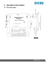
1
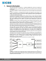
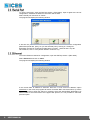
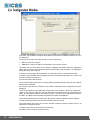
Nome File: EAAM009504EN.docx Rev. 04 Data: 18/06/2013 ID Documento: EAAM0095 Prodotto: GATEWAY Modbus/TCP ii 1. General information................................................................................................. 4 1.1 Input voltage ......................................................................................................... 5 1.2 Ethernet connector ............................................................................................... 5 1.3 Serial port ............................................................................................................. 5 1.4 Digital inputs ......................................................................................................... 5 1.5 Digital outputs with relays ..................................................................................... 6 1.6 Dip switches ......................................................................................................... 6 1.7 Non-volatile memory ............................................................................................. 6 2. PC Configuration Program ..................................................................................... 6 2.1 Program Installation .............................................................................................. 6 2.2 Program Execution ............................................................................................... 6 2.2.1 If Installed Individually .................................................................................... 6 2.2.2 If Installed with SicesSupervisor ..................................................................... 6 2.3 Program Description ............................................................................................. 7 2.3.1 Serial Port....................................................................................................... 8 2.3.2 Ethernet .......................................................................................................... 8 2.3.3 GMT Search ................................................................................................... 9 2.4 Configuration Window......................................................................................... 10 3. ModBus protocol ................................................................................................... 14 3.1 ModBus commands implemented. ..................................................................... 14 3.2 Data Transfer Formats........................................................................................ 14 3.2.1 BOOL_XX..................................................................................................... 14 3.2.2 US_XX.......................................................................................................... 15 3.2.3 UL_XX .......................................................................................................... 15 3.2.4 DOT_02 ........................................................................................................ 16 3.2.5 STR_XX ....................................................................................................... 16 3.2.6 SHEX_XX ..................................................................................................... 16 3.2.7 Registers assignment ................................................................................... 16 3.3 Summary of registers.......................................................................................... 17 3.3.1 Input Registers ............................................................................................. 17 3.3.2 Holding Registers ......................................................................................... 17 3.4 Detailed description of input registers ................................................................. 19 3.4.1 Register 30001 ............................................................................................. 19 3.4.2 Register 30002 ............................................................................................. 19 3.4.3 Register 30003-005 ...................................................................................... 19 3.5 Detailed description of holding registers ............................................................. 20 3.5.1 Register 40001 ............................................................................................. 20 3.5.2 Register 40002 ............................................................................................. 20 3.5.3 Registers 40101-104 .................................................................................... 20 3.5.4 Registers 40105-124 .................................................................................... 20 3.5.5 Registers 40125-126 .................................................................................... 20 3.5.6 Registers 40127-128 .................................................................................... 20 3.5.7 Register 40129 ............................................................................................. 20 3.5.8 Registers 40130-131, 40132-133, 40134-135, 40136-137 ........................... 20 3.5.9 Registers 40138-139 .................................................................................... 20 3.5.10 Register 40140 ........................................................................................ 21 USER MANUAL 3.5.11 3.5.12 3.5.13 3.5.14 3.5.15 3.5.16 3.5.17 3.5.18 3.5.19 3.5.20 3.5.21 Registers 40141-156 ............................................................................... 21 Registers 40157-172 ............................................................................... 21 Register 40173 ........................................................................................ 21 Registers 40174-175 ............................................................................... 21 Registers 40176-177, 40178-179, 40180-181, 40182-183...................... 21 Register 40184 ........................................................................................ 21 Register 40185 ........................................................................................ 21 Registers 40201-204 ............................................................................... 21 Registers 40301-302 ............................................................................... 21 Registers 40303-318 ............................................................................... 22 Registers 40319-334 ............................................................................... 22 4. Reporting faults via Ethernet ................................................................................ 22 5. "Live" reporting via Ethernet ................................................................................ 22 6. Description of the hardware ................................................................................. 23 6.1 View from above ................................................................................................. 23 6.2 Dimensions and drilling template for assembly ................................................... 24 GATEWAY ModBus/TCP iii This manual describes the SICES s.r.l. "Gateway ModBus/TCP" and the PC program for configuring the device. The abbreviation GMT will be used to indicate this device throughout the document. The GMT is a simple and compact product used to let devices with serial ports communicate in an Ethernet network. It comes in an aluminium case, and is mounted on the wall with four holes. It must be connected to a standard Ethernet network that supports TCP/IP protocol. The network interface built into the product can manage a maximum speed of 10 Megabits per second. The device can also be connected to a 100 megabits per second network using a hub or switch that supports both speeds. The GMT does not support standard DHCP network protocol, in other words the automatic assignment of IP addresses in a network. This protocol is widely used in Windows networks, with a server (called the DHCP server) that performs this function. If the network where the GMT will be installed uses DHCP, disable an IP address on the DHCP server (so that server cannot use it) and assign it to the GMT. Contact the network administrator to perform this operation. The GMT can also be used in Internet (because Internet supports TCP/IP protocol). In this case however, the GMT must have a static IP address (i.e. a unique IP address for Internet). Static IP addresses must be acquired from the competent authority. The GMT has a serial port, which can be configured for RS-232 and RS-485 standard. This serial port can be used to connect one or more devices that implement Modbus protocol in RTU mode. These devices must be slaves in serial communication. In other words they must only respond to queries and should never transmit on their own initiative. Once the GMT has been installed and configured, you can communicate with devices connected to the serial port of any PC in the network, indicating the IP address assigned to the GMT and the address of the device to query. On the PC, you should use the Ethernet version of the ModBus protocol, called Modbus/TCP. The GMT converts ModBus/TCP messages into Modbus/RTU format and sends them to the serial port. On receipt of the response, it converts the same into Modbus/TCP format and transmits the same via Ethernet to the IP address of the PC that sent the query. The GMT also acts as a network concentrator: in fact, it supports up to four simultaneous connections from the network. This means the devices can be queried "simultaneously" by four different PCs. This would not otherwise be possible, given the master/slave nature of Modbus Protocol, which envisages only one master (sending queries) and many slaves (responding). Of course, as simultaneous connections increase, there will be a drop in performance for a single connection. The following diagram shows the information flow in a practical example: Ethernet, ModBusTCP/IP Bus RS-485, ModBus RTU In addition, the GMT has four digital inputs and four digital outputs that can be used as you wish. Using a certain ModBus address (255, which is normally not used), the same GMT can be queried via Ethernet (rather than a device connected to the serial port), to acquire the status of inputs and control the outputs. 4 USER MANUAL SICES supplies PC software with the GMT, which is simple and easy to use, for device configuration both via the serial port or Ethernet. This software runs in WINDOWS 98/2000/NT/XP. It does not run in WINDOWS 95 or earlier. The GMT must be supplied with a voltage from 7.5 to 32 VDC, using connector J8. In fact it is designed to be used with our generator management boards, powered by the genset starter battery. Connector J8 also has a ground terminal. The device has a standard RJ45 8-pole Ethernet connector. There are two lights next to the connector: the green light indicates connection to the Ethernet network, the yellow light indicates data transmission on the network. There is a nine-pin male DB connector with standard RS-232 PC serial port pin configuration. Use a standard crossover cable to connect a device (or PC during configuration) to the serial port. Observe the following wiring diagram: There is also a three-pole terminal block for connection to a RS-485 standard network. The three poles are named with standard terminology. The poles are marked A/B and +/- for data transmission. To connect one or more devices to this terminal block you will need a 2-pole screened cable. See diagram below. Device 1 Device n. There is also a toggle switch (SW2) to enable/disable a 120 ohm termination resistance on the RS-485 network. Use a toggle switch (SW1) to enable the RS-232 connector or the RS-485 terminal block. This port is normally used to connect one or more serial devices that implement the Modbus (RTU) protocol, as a slave. It can sometimes be used to configure the GMT. The board has four optically isolated digital inputs (connector J6). Each digital input has a 1pole terminal board. To activate an input, connect terminal J6.5 (negative) to the relevant terminal. USER MANUAL 5 The I/O board has four digital outputs with relays (0.5 Amp max. on contacts). Each digital output has a two-pole terminal block for the closing contact of the relay (connector J2). The relays are controlled by the operator through the PC software configuration. The board has a bank of two dip switches (SW3), numbered one and two. Dip switch 1 is used when you want to use the serial port (RS-232 or RS-485) to configure the GMT (if closed down). Dip switch 2 is not used. Used to store the GMT configuration. The information stored includes the IP address, TCP port, etc. Together with the GMT (Gateway Modbus/Tcp), SICES s.r.l. provides a PC software to supervise and configure the device via both Ethernet and the serial port. This software is named “ModBus Data Gateway Configuration Tool” (the executable file is named MDGConfig.exe). The program is sold individually or together with SicesSupervisor supervision software. In the first case, run the “Setup.exe” file on the installation CD to install the program. In the second case, select “MDGConfig.exe” during SicesSupervisor installation. The program can be executed in two ways: by double-clicking on the "MDGConfig.exe” file, or by selecting “ModBus Data Gateway Configuration Tool” from the start menu. The “MDGConfig.exe” is in the “C:\Programs\Sices\Modbus Data Gateway Configuration Tool” folder; from the start menu, follow the “Programs Sices Modbus Data Gateway Configuration Tool” path. The “MDGConfig.exe” is in the “C:\Programs\Sices\SicesSupervisor” folder; from the start menu, follow the “Programs Sices SicesSupervisor” path. 6 USER MANUAL When launched, the program asks for language selection: Once the desired language is selected, click on “OK” to confirm. The program will display the following window: Choose whether the program should configure the device via Ethernet or via the serial port. It is recommended to configure the device for the first time with the serial port. Use the serial port if the current GMT IP address is not recognized and the Ethernet network being used does not support the UDP protocol. USER MANUAL 7 To use the serial port, close the GMT dip switch 1 (SW3 bank). Open it again at the end of configuration, otherwise the Ethernet connection will not work. Select "Serial port" and click on "Finish". The program will display the following window: It will then be possible to select the serial port to be used and to set the configuration parameters (baud rate, parity, etc.) for the selected port by clicking on "Configure". By default, the GMT is configured for 9600 baud, no parity, 1 start bit and 1 stop bit. Once finished, click on "OK" (further details in section 2.3.3). To use the Ethernet network for configuration, open the GMT dip switch 1 (SW3 bank). Select “Ethernet” and click on "Next". The program will display the following window: If the current GMT IP address is unknown, leave the "I know current IP address" option unselected. In this case, the program will search for all the GMT connected online, by means of the UDP protocol. When the search is complete, select the desired GMT identified by its serial number. If the network does not support UDP protocol, it is not possible to select the previous option. 8 USER MANUAL If the IP address is known, select the previous option and type this address in the relevant field (displayed when selecting the option): Click on "Finish" (further details in section 2.3.3). The program will now try to contact the GMT(S) online. The following window will be displayed during the search: Search for devices... Once finished, the detected GMT list will be displayed in the left hand side of the window above (if no GMT is detected, an error message will be displayed). Each GMT is displayed with its network interface MAC address, which is unique. Click on one of them to start the configuration. USER MANUAL 9 From here, it is possible to configure all the GMTs connected to the Ethernet network or to the PC serial port. The menu bar is at the top of the window. It only has two items: Exit: To close the program Search: To search for GMTs, as described in the previous section. The status bar is at the bottom of the window. It displays information about the application status, but no controls can be performed from here (there are some exceptions). The displayed information (from left to right) is: The used communication device (Ethernet or serial port) and the communication status. A counter for the ModBus/TCP messages sent in the Correct/Wrong format. This counter will be reset by double-clicking on it. The current system date and time. On the left hand side, there is a list of all the GMTs detected (listed according to their network interface MAC address). On the right hand side of the window, once a GMT is selected, all the configuration tools are displayed. There are five steps for the configuration, respectively in the "System", "Network", "Serial port", "Alarms" and "Security" tabs (the "Alarms" tab might not be displayed if not supported by the GMT). The first step is shown in the previous figure. This step is for configuring the name for the GMT. In addition, the information acquired by the GMT are displayed: Three fields that identify the manufacturer, the product, and the software release installed. The input status (the boxes are red if the relevant inputs are active). The output status (the boxes are red if the relevant outputs are active). Double-click on an output box to change its status. The status of the two dip switches of the SW3 bank. The status of the board non-volatile memory. 10 USER MANUAL Click on the "Network" tab to display the following window: This tab is for configuring the GMT Ethernet. An IP address is assigned to the GMT, the "subnet mask" for its network and the TCP port to be used are configured. For the first two pieces of information, contact the network administrator (see chapter 1 for notes on the DHCP protocol). The TCP port should always be set at 502, if possible. It is also possible to set the network gateway IP address (router, or other) for those cases when the GMT and the PC it should work with are in two separate networks (ask the network administrator). At the top of the tab, the network interface MAC address is displayed. USER MANUAL 11 Click on the "Serial port" tab to display the following window: This tab is for configuring the GMT serial port. Communication speed and parity type are configured here. If Sices boards are used to control the gen-sets, a list (by type and serial address) of devices can be created: this list will be periodically checked by the GMT if the Ethernet connection is not active, in order to detect possible faults and notify them on the Ethernet. Up to 16 devices can be configured. Click on the "Alarms" tab to display the following window: 12 USER MANUAL This tab is for configuring the IP addresses where to send messages for possible alarms detected on SICES boards connected to the GMT serial port. If the list "Configured IP addresses" is left empty, the alarm messages will be sent in 'broadcast' mode (that is to all the PCs connected on the network) by means of the UDP network protocol. If the network does not support this protocol (or the 'broadcast' mode), up to four IP addresses can be added to the above-mentioned list: the alarm messages will be sent only to these IP addresses. To add an IP address, type it in the field above the list, then click on "Add". To remove an IP address from the list, click on it from the list and then click on "Remove". When one of the SICES boards connected to the serial port is in an alarm status, the GMT sends one or more network messages at regular intervals. The box “Delay between alarm signals” allows setting a delay (in seconds) between these two messages. By setting a value different from 0 in the box “Delay between 'alive' signals”, the GMT will send a Keep Alive network message at regular intervals. The aim of this message is to inform those PCs that are connected that the GMT is working correctly. This message also includes a status indicator for the serial communication with the SICES boards, so that the PC can detect faults also between the GMT and the boards. These messages are sent to the same IP address than for the alarms (or in 'broadcast' mode if no IP address is set). Click on the "Security" tab to display the following window: This tab is for configuring the GMT security options. It is possible to set a password, which will be required when connecting for Ethernet configurations. In addition, it is possible to create a list of up to four IP addresses for Ethernet connection. If no address is set, the Ethernet connection is available from any IP address. If the network uses the DHCP, this function cannot be used, since not all the networked PC addresses are known or are unmodified. Once all the steps have been performed, even if only one option has been changed, the "Update" button will be enabled. The configuration will be sent to the GMT by clicking on it (NB: if the program is closed, another GMT is selected, or a new search is launched without first clicking on "Update", the configurations made will be lost). By clicking on "Cancel", it will be possible to read the current configuration form the GMT (this is an automatic operation performed when clicking on a GMT on the left hand side of the window). USER MANUAL 13 The Modbus communication protocol is used in RTU mode. The equivalent ModBus/TCP protocol is used for Ethernet. The indications in this chapter apply to both versions of the protocol. The GMT recognizes the following standard ModBus commands: COMMAND DESCRIPTION 03 Read Holding Register 04 Read Input Register 06 Preset Single Holding Register 16 Preset Multiple Holding Register 17 Report Slave ID 22 Mask Write Holding Register 23 Read and Write Holding Register 43 Read device ID The GMT doesn’t implement the ModBus command that allow the transfer of information Boolean. as a matter of fact that there are MODBUS sub-assemblies (e.g. JBUS) intended for that specific purpose. By using only the mentioned commands to transfer all the information, the GMT is compatible with these MODBUS derived protocols. The above facts do not mean that the GMT do not use bit information. In fact the latter information is compacted in a (16 bits) MODBUS register that is to be interpreted bit by bit. In the specific device documents a table showing the information associated with each bit is provided, together with the corresponding bit value. Numerical information could be absolute or + values (the most part are absolute values). The + variables are transmitted by using the “complement to two” approach. With such an approach a negative value is transmitted by inverting all the bits of the relevant absolute value and summing 1. As a result, the negative values are identified by numbers having the most significant bit equal to 1. All the numerical pieces of GMT information are displayed with the relevant physical measurement units. In some instances the physical unit values are acquired and sometimes displayed by the devices with a somewhat higher accuracy by including the decimals. The decimals are also transmitted via MODBUS. The tables shown in the specific device documents report for each register the availability of decimal values, together with the related number of bits. A zero decimal bits register has no decimal content. The decimal bits are positioned as the less significant bits. E.g. an eight decimal bits register has the decimal bits in the 8 less significant positions. To obtain the value of the register from the relevant binary information, the register must be divided by two raised to the number of decimal bits. It should be noted that the above considerations (parameter sign and decimal part of the register) could be all applied to a single information. In the following part of this paragraph are described in detail the codes used in this document to describe the information transferred through the MODBUS protocol. This code identifies a bit data information string. The information might be contained in one or more contiguous registers. The “XX” field identifies the number of registers used to the purpose of recording the information. In the specific device paragraphs, a table is included providing the description of what is associated with each bit of the relevant MODBUS registers. 14 USER MANUAL This code identifies unsigned numerical information associated with a max of 16 bits. Some few bits could represent the decimal part of the numerical information. The “XX” field indicates the number of decimal bits. This type of information uses always a single register. The minimal register value, in this format, is zero. The max value is 65535 ((2^16)-1) divided by two raised to the number of decimal bits. N° of decimal bits Formula Maximum value 0 65535 / (2^0) 65535 4 65535 / (2^4) 4095,9375 8 65535 / (2^8) 255,99609375 12 65535 / (2^12) 15,999755859375 Few examples follow: 1) US_00 (no decimals) While reading 11405 (0x2C8D) from the MODBUS register, to find the actual value it is needed to: a) divide by two rose to the number of digital bits 11405/ (2^0) = 11405. I.e. the register number 11405 represents actually the value 11405. 2) US_08 (eight decimal bits). While reading 11405 (0x2C8D) from the MODBUS register, to find the actual value it is needed to: a) divide by two raised to the number of digital bits 11405 / (2^8) = 44,55078125. I.e. the number 11405 represents the value 44,55078125. This code identifies unsigned information using up to 32 bits. Some few bits might represent the decimal part of the information. The field “XX” indicates the number of decimal bits. The information uses always two registers. The minimum information value in this format is zero. The max information value is 4294967295 ((2^32)-1) divided by two raised to the number of digital bits. N° of decimal bits Formula Max value 0 4294967295 / (2^0) 4294967295 8 4294967295 / (2^8) 16777215,99609375 16 4294967295 / (2^16) 65535,9999847412109375 24 4294967295 / (2^24) 255,999999940395355224609375 Some few examples follow: 1) UL_00 (no decimal bits). While reading 34464 in the lower index register and 1 in the upper index register, to find the actual value it is needed to: a) Multiply the upper register by (2^16) 1*65536 = 65536 b) Sum the lower register 65536+34464 = 100000 c) Divide by two raised to the number of digital bits 100000 / (2^0) = 100000 Therefore the couple of registers: 34464 (lower) and 1 (upper) represent the value 100000. 2) UL_08 (eight decimal bits). While reading 34464 in the lower index register and 1 in the upper index register, to find the actual value it is needed to: a) Multiply the upper register by (2^16) 1*65536 = 65536 b) Sum the lower register 65536+34464 = 100000 c) Divide by two raised to the number of decimal bits 100000 / (2^8) = 390,625 Therefore the couple of registers 34464 (lower) e 1 (upper) represent the value 390,625. USER MANUAL 15 This code indicates numeric information without a sign expressed in 32 bits, representing the points style of the IP addresses. The information always occupies two registers. DOT_02 could be the IP address, which is transferred using the holding registers 40127-40128. The IP address is assumed to be 192.168.1.2 for example. It will be transferred as follows: Register Value (HEX) Low part High part 40127 0x0102 (0x02) 2 (0x01) 1 40128 0xC0A8 (0xA8) 168 (0xC0) 192 This code identifies an ASCII type string of information. The information might be located in one or more contiguous registers. The XX field indicates the number of registers. The strings are transferred via MODBUS by recording two characters per register and using a number of consecutive registers. As an example the string might represent the GMT name (that will be therefore identified by using the STR_20 code). The GMT name consists therefore of max 40 characters (20 registers by 2 characters). The string terminator or ASCII 00 must also be included. As an example the name “NUOVO IMPIANTO” will be transferred as: Register HEX Value Lower Section Upper Section 40105 0x554E 0x4E (“N”) 0x55 (“U”) 40106 0x564F 0x4F (“O”) 0x56 (“V”) 40107 0x204F 0x4F (“O”) 0x20 (“ ”) 40108 0x4D49 0x49 (“I”) 0x4D (“M”) 40109 0x4950 0x50 (“P“) 0x49 (“I”) 40110 0x4E41 0x41 (“A”) 0x4E (“N“) 40111 0x4F54 0x54 (“T”) 0x4F (“O”) 40112 0x0000 0x00 (terminator) 0x00 (terminator) 40113 0x0000 0x00 (terminator) 0x00 (terminator) 40114 0x0000 0x00 (terminator) 0x00 (terminator) 40115 0x0000 0x00 (terminator) 0x00 (terminator) 40116 0x0000 0x00 (terminator) 0x00 (terminator) 40117 0x0000 0x00 (terminator) 0x00 (terminator) 40118 0x0000 0x00 (terminator) 0x00 (terminator) 40119 0x0000 0x00 (terminator) 0x00 (terminator) 40120 0x0000 0x00 (terminator) 0x00 (terminator) 40121 0x0000 0x00 (terminator) 0x00 (terminator) 40122 0x0000 0x00 (terminator) 0x00 (terminator) 40123 0x0000 0x00 (terminator) 0x00 (terminator) 40124 0x0000 0x00 (terminator) 0x00 (terminator) This code identifies a string of HEX of information. The information might occupy one or more contiguous registers. The XX field indicates the number of registers. The hex strings are transmitted via MODBUS by recording four hexadecimal digits per register and using a number of consecutive registers. An example of a string can be the MAC of the network that is transferred by using the 30103-30105 input registers (identified with the SHEX_03 code). The MAC consists therefore of 12 hex digits (# 3 registers by 4 digits each). As an example the MAC serial number “000008EF94CT” is transferred as follows: Register HEX value 30103 0x94C7 30104 0x08EF 30115 0x0000 Some registers are reserved to specific functions to be assigned later on. Some others have limited applicability, due to the device configuration, or limited accessibility (write or read only). Limitations are identified with the # symbol in the following tables, at the fourth column. A detailed description is provided in the register description paragraph. 16 USER MANUAL Register 30001 30002 30003 Format BOOL_01 BOOL_01 SHEX_03 Register 40001 40002 Format QUANTITY BOOL_01 Digital output state # Controls US_00 40101 40105 40125 40127 40129 40130 40132 40134 40136 40138 40140 40141 40142 40143 40144 40145 40146 40147 40148 40149 40150 40151 40152 40153 40154 40155 40156 40157 40158 40159 40160 40161 40162 40163 40164 40165 40166 40167 STR_04 STR_20 DOT_02 DOT_02 US_00 DOT_02 DOT_02 DOT_02 DOT_02 UL_00 US_00 US_00 US_00 US_00 US_00 US_00 US_00 US_00 US_00 US_00 US_00 US_00 US_00 US_00 US_00 US_00 US_00 US_00 US_00 US_00 US_00 US_00 US_00 US_00 US_00 US_00 US_00 US_00 QUANTITY Digital input state Dip switch state Network interface MAC address M.U. - M.U. - # Password Name associated with GMT Network sub-net mask IP address associated with GMT TCP port to use 1st IP address from which a connection is accepted 2nd IP address from which a connection is accepted 3rd IP address from which a connection is accepted 4th IP address from which a connection is accepted Serial port baud rate Serial port parity type 1st serial address for automatic scanning 2nd serial address for automatic scanning 3rd serial address for automatic scanning 4th serial address for automatic scanning 5th serial address for automatic scanning 6th serial address for automatic scanning 7th serial address for automatic scanning 8th serial address for automatic scanning 9th serial address for automatic scanning 10th serial address for automatic scanning 11th serial address for automatic scanning 12th serial address for automatic scanning 13th serial address for automatic scanning 14th serial address for automatic scanning 15th serial address for automatic scanning 16th serial address for automatic scanning 1st type of device for automatic scanning 2nd type of device for automatic scanning 3rd type of device for automatic scanning 4th type of device for automatic scanning 5th type of device for automatic scanning 6th type of device for automatic scanning 7th type of device for automatic scanning 8th type of device for automatic scanning 9th type of device for automatic scanning 10th type of device for automatic scanning 11th type of device for automatic scanning Baud - USER MANUAL 17 18 Register 40168 40169 40170 40171 40172 40173 40174 40176 40178 40180 40182 40184 40185 Format US_00 US_00 US_00 US_00 US_00 US_00 DOT_02 DOT_02 DOT_02 DOT_02 DOT_02 US_00 US_00 40201 STR_04 # Login Password 40301 40303 40304 40305 40306 40307 40308 40309 40310 40311 40312 40313 40314 40315 40316 40317 40318 40319 40320 40321 40322 40323 40324 40325 40326 40327 40328 40329 40330 40331 40332 40333 40334 DOT_02 US_00 US_00 US_00 US_00 US_00 US_00 US_00 US_00 US_00 US_00 US_00 US_00 US_00 US_00 US_00 US_00 US_00 US_00 US_00 US_00 US_00 US_00 US_00 US_00 US_00 US_00 US_00 US_00 US_00 US_00 US_00 US_00 # # # # # # # # # # # # # # # # # # # # # # # # # # # # # # # # # USER MANUAL QUANTITY 12th type of device for automatic scanning 13th type of device for automatic scanning 14th type of device for automatic scanning 15th type of device for automatic scanning 16th type of device for automatic scanning Non-volatile memory state Network gateway IP address (router or other) 1st IP address for alarm transmission 2nd IP address for alarm transmission 3rd IP address for alarm transmission 4th IP address for alarm transmission Delay between two network alarm messages Delay between two "live" network messages IP address (for fault reporting) 1st serial address of device in alarm state 2nd serial address of device in alarm state 3rd serial address of device in alarm state 4th serial address of device in alarm state 5th serial address of device in alarm state 6th serial address of device in alarm state 7th serial address of device in alarm state 8th serial address of device in alarm state 9th serial address of device in alarm state 10th serial address of device in alarm state 11th serial address of device in alarm state 12th serial address of device in alarm state 13th serial address of device in alarm state 14th serial address of device in alarm state 15th serial address of device in alarm state 16th serial address of device in alarm state 1st device off-line serial address 2nd device off-line serial address 3rd device off-line serial address 4th device off-line serial address 5th device off-line serial address 6th device off-line serial address 7th device off-line serial address 8th device off-line serial address 9th device off-line serial address 10th device off-line serial address 11th device off-line serial address 12th device off-line serial address 13th device off-line serial address 14th device off-line serial address 15th device off-line serial address 16th device off-line serial address M.U. Sec Min - Contains the status of board digital inputs. Bit 0 1 2 3 4 5 6 7 8 9 10 11 12 13 14 15 Description Input 1 Input 2 Input 3 Input 4 Value 1 = active, 0 = inactive 1 = active, 0 = inactive 1 = active, 0 = inactive 1 = active, 0 = inactive Contains the status of the board dip switches. Bit 0 1 2 3 4 5 6 7 8 9 10 11 12 13 14 15 Description Dip switch 1 Dip switch 2 Value 1 = closed, 2 = open 1 = closed, 2 = open Dip switch 1 on startup Dip switch 2 on startup 1 = closed, 2 = open 1 = closed, 2 = open Network interface MAC address on GMT. The MAC address is a unique 6-byte number for all global network interfaces. USER MANUAL 19 Contains the status of the board digital outputs. Bit 0 1 2 3 4 5 6 7 8 9 10 11 12 13 14 15 Description Output 1 Output 2 Output 3 Output 4 Value 1 = active, 0 = inactive 1 = active, 0 = inactive 1 = active, 0 = inactive 1 = active, 0 = inactive The value of this register is not significant. The write operation will end the configuration process via an Ethernet network. It is a write-only register Write-only registers. To set password protection for configuration via Ethernet. For configuring the name to be associated with the GMT. This name may be used to identify separate GMTs if more than one is connected to the same network. Used to configure the sub-net mask of the network in which the GMT is installed. The subnetmask is a 4-byte numeric value (e.g. 255.255.255.0). Used to configure the GMT IP address. The IP address is a 4-byte numeric value (e.g. 192.168.1.1). For configuring the TCP port to use. The TCP port is a 16-bit numerical value. Always use value 502 if possible. Used to configure the IP addresses enabled for Ethernet connection. If the IP address is 0.0.0.0 the address has not been set. If none of the four addresses has been set, an Ethernet connection will be accepted from any IP address. Used to configure the serial port communication speed. It is directly expressed in baud (set 9600 for a baud rate of 9600). 20 USER MANUAL Used to configure the type of parity to use for the serial port. The following values can be used: 0: no parity 1: odd parity 2: even parity Used to configure the addresses of devices connected to the serial port which must be automatically controlled by the GMT in order to detect anomalies and report the same via Ethernet (only valid for Sices boards). The address may be 1..247, disabled if set to 0. Used to configure the type of devices connected to the serial port which must be automatically controlled by the GMT in order to detect anomalies and report the same via Ethernet (only valid for Sices boards). The following values can be used: 0: disabled 1: DST4600A 2: DST4601, DST4400, GDC Indicates the status of board's non-volatile memory. The following values can be used: 0: errors 1: no error 2: default configuration values Used to configure the IP address associated with the network gateway (router or other) if the GMT and PC you are connecting are on two different Ethernet networks. Used to configure the IP address to which alarm and "live" messages will be sent. If the IP address is 0.0.0.0 the address has not been set. If none of the four addresses is set, the alarm and "live" messages will be broadcast with UDP. Used to configure the delay (in seconds) with which alarms are sent over the network. Used to configure the delay (in minutes) with which messages are sent "live" over the network. Write-only registers. Used to provide a password (login) when you start a configuration operation via Ethernet and the GMT is protected. Read-only registers: indicate the IP address of the GMT. Used for automatic anomaly reporting in a network on devices connected to the serial port. USER MANUAL 21 Read-only registers: contain the addresses of devices in a state of alarm connected to the serial port. Used for automatic anomaly reporting in a network on devices connected to the serial port. Value 0 means the device is not in a state of alarm. Registers are read-only: they contain the addresses of the off-line devices connected to the serial port (do not respond to GMT queries). A value of 0 means the device is online. When used with Sices generator management boards, a list of devices can be configured (by type and serial address) that the GMT will periodically check when it has no active Ethernet connection, to detect any anomalies and report them via Ethernet. You can configure up to 16 devices. When an anomaly is detected, a message is sent every five seconds using UDP protocol to all the IP addresses configured (or broadcast if no IP has been configured). The message consists of the following: Eleven standard protocol header characters A character "R" (Ring) 6 bytes for the GMT MAC address (sender) 6 bytes for the MAC address of the receiver (broadcast, all 0xff) two characters as a transaction index two characters with the length in bytes of the following a standard "Preset Holding Register" message containing registers 40301 .. 40318, with the Modbus/TCP protocol. These registers contain the IP address of the GMT and the addresses of all the devices in a state of alarm. When properly configured, the GMT can periodically send a message via the network using UDP protocol to all the IP addresses configured (or broadcast if no IP address has been configured). This message reports the normal GMT performance (the absence of this message should trigger alarms on the controller PC). The message consists of the following: 22 Eleven standard protocol header characters An "L" (Live) character 6 bytes for the GMT MAC address (sender) 6 bytes for the MAC address of the receiver (broadcast, all 0xff) two characters as a transaction index two characters with the length in bytes of the following a standard "Preset Holding Register" message containing registers 40301 .. 40335, with Modbus/TCP protocol. These registers contain the IP address of the GMT and the addresses of all the devices in a state of alarm and all OFF-LINE devices. USER MANUAL USER MANUAL 23 24 USER MANUAL This document is owned by SICES s.r.l.. All rights reserved. SICES s.r.l. reserves the right to modify this document without prior notice. SICES has made any effort to ensure that the information herein provide are correct; in any case SICES does not assume any liability for the use these information. The disclosure by any means of this document to third parties is not allowed. SSSTTTTTGHTY 1