
1
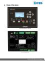
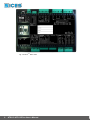
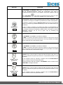
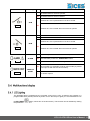
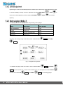
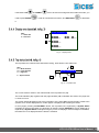
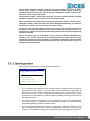
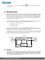
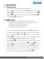
File Name: EAAM048102EN Rev. 02 Date: 26/09/2014 ID Document: EAAM030481 Product: ATS115-ATS115Plus 1. Information on security ........................................................................................... 3 2. Information on the disposal .................................................................................... 3 3. Definitions ................................................................................................................ 4 .................................................................................................... 5 ........................................................................................................... 7 ........................................................................................................... 7 ............................................................................................ 8 ....................................................................................... 10 ........................................................................................ 11 ................................................................................................. 11 ..................................................................................... 12 ...................................................................... 12 .................................................................. 13 ......................................................................... 13 ...................................................................................................... 14 ..................................................................................... 14 .............................................................................. 20 ................................................................... 24 ....................................................................................... 27 ii 6. Working principle .................................................................................................. 28 ............................................................................................................. 28 ................................................................................................................ 29 ........................................................................................................... 30 7. Special settings ..................................................................................................... 31 ............................................................................................. 31 ............................................................................................... 31 ATS115-ATS115Plus User’s Manual This manual must be conserved with care and be always available for a rapid consultation. It must be read carefully and understood in every paragraph by who will use and periodically maintain the device. If the manual is lost or damaged, ask the Technician/Manufacturer for a copy, by providing the model, the code, the serial number and the year of construction of the device. A lot of accidents are caused by unsufficient knowledge and by lack of security rules implementation to comply with during the operations of working and/or maintenance. In order to avoid accidents, before carrying out any working and/or maintenance operation, read, understand and follow the indications and warnings contained in this manual. The security messages contained in this manual are represented by the following indications: WARNING! This indication is used in case of dangers that, if not avoided, may cause malfunctioning to things or persons. INFORMATION! This indication is used to provide useful information and clarifications during an operation or procedure. INFORMATION! Disposal of old electric and electronic devices (valid for the European countries that implemented recycling systems). Products having a crossed garbage wheelie bin cannot be disposed together with the normal garbage. Old electric and electrical products must be recycled in a proper structure, able to process these products and dispose their components. In order to know where and how to send these products near you, please contact the proper municipal office. Right recycling and disposal help to preserve nature and to prevent harmful effects to health and environment. ATS115-ATS115Plus User’s Manual 3 STOP: it is used to indicate an anomaly that makes impossible the normal operation of the plant. WARNING: it is used to indicate an anomaly that requires an operation intervention. ACB (“A Circuit Breaker”): breaker or component for the management of the changeover between Source A and the Load. BCB (“B Circuit Breaker”): breaker or component for the management of the changeover between Source B and the Load. SOURCE A: it is used to indicate the genset or the mains connected on one side of the ACB. SOURCE B: it is used to indicate the genset or the mains connected on one side of the BCB. LOAD: loads electric supply. It can be connected whether to the Source A or to the Source B. MAINS: public electric supply. GENSET: electric supply connected to the genset alternator. DIF (“Digital Input Function”): the code that follows is used to set the digital inputs. DOF (“Digital Output Function”): the code that follows is used to set the digital outputs. AIF (“Analogue Input Function”): the code that follows is used to set the analogue inputs. 4 ATS115-ATS115Plus User’s Manual Fig. 1 ATS115-ATS115Plus Front View Fig. 2 ATS115 Back View ATS115-ATS115Plus User’s Manual 5 Fig. 3 ATS115Plus Black View 6 ATS115-ATS115Plus User’s Manual Fig. 1 –ATS115-ATS115Plus Front Panel ATS115-ATS115Plus KEY 1 – Buttons 2 – Light indicators The controls are made up of 12 buttons (1a, 1b, 1c, 1d, 1e, 1f). In addition, on the front panel there are light indicators (2a, 2b, 2c). ATS115-ATS115Plus User’s Manual 7 BUTTON MODE UP OFF/RESET PROGRAM FUNCTION The group is disabled; warnings and stops are cancelled. It is possible to access to the parameters configuration. The controller sets the genset manual operation. MODE DOWN MAN (Manual) Press the button START/STOP A set as genset. to start/stop the Source A when it is Press the button START/STOP B set as genset. to start/stop the Source B when it is With source live and in tolerance: Press the button ACB for the manual opening/closing control of the loads breaker/contactor on Source A. Press the button BCB for the manual opening/closing control of the loads breaker/contactor on Source B. Ref. 1a AUTO (Automatic) Esc/SHIFT Ref. 1b The controller sets the automatic changeover of the loads supply source and intervenes in case of faults on one of the two sources. In program mode, it allows to cancel a variable value change, come back to the upper menu, and exit the programming. By pressing it for two seconds in any of the menu, it allows to exit the programming saving the position for a future return. By pressing it for two seconds in any of the menu, it provides the engine status in the upper line. In OFF/RESET mode, according to the page selected, by pressing it together with ENTER for at least 5 seconds, it can reset the counters, reload the default values for the programming parameters or cancel the history log. If used during the keyboard regulation functions, it aborts the function. The multifunctional display buttons allow to select the previous or next page of display in all mode but PROGRAM. In the PROGRAM mode, they are used to place the cursor during the strings insertion phase. The horizontal buttons, combined with the button ESC/SHIFT , can adjust the contrast. To reduce the contrast (lighten), press the ESC/SHIFT with the LEFT button together button. To increase the contrast (darken), press the LEFT/RIGHT Ref. 1c 8 ESC/SHIFT ATS115-ATS115Plus User’s Manual button together with the RIGHT button. BUTTON FUNCTION In PROGRAM and HISTORY LOG modes, it is possible to scroll the menus and the variables/registrations. During the configuration, they allow to increase/decrease the value of the variable. Using them together with the button ESC/SHIFT , they allow to scroll the menus ten items at a time or increase/decrease the value of the variable by ten units at a time. In PROGRAM, it allows to start programming and to enter in submenus, start an operation of change of a variable or parameter and confirm said operation. In HISTORY, it allows to start the HISTORY LOG and to enter in the selected archive, to “accept” any possible fault warning on the non-volatile memory at the start-up. ENTER/ACK Ref. 1d In case of alarm or warning, by pressing the button it acknowledges the presence of a fault and stops the alarm. By pressing the button again, it resets any possible warning if the operating conditions have come back as normal. Interruption warnings can be set up again, only by activating the “OFF/RESET” mode. In “OFF/RESET” and “AUTO”, the button is disabled. ACB Ref. 1f In “MAN”, it is used to open and/or close the contactor on the Source A to the Load. The closing of the Load to the Source A it’s only possible if the related electric measures are in the tolerance range. In “OFF/RESET” and “AUTO”, the button is disabled. BCB Ref. 1f In “MAN”, it is used to open and/or close the contactor on the Source B to the Load. The closing of the Load to the Source B it’s only possible if the related electric measures are in the tolerance range. In MAN mode, it can be used to control the start and stop of the source A when it is configured as genset (if the Source A represents the Mains, it has no effects). START / STOP SOURCE A Ref. 1e At the controller power-up, pressing it together with the START/STOP B button, it allows to access to special functions. Pressing the button with the controller in OFF/RESET mode, it carries out the LAMP TEST of all light indicators. In MAN mode, it can be used to control the start and stop of the source B when it is configured as genset (if the Source B represents the Mains, it has no effects). START / STOP SOURCE B At the controller power-up, pressing it together with the START/STOP A button, it allows to access to special functions. Ref. 1e ATS115-ATS115Plus User’s Manual 9 Led off Led steady on Led flashing Warning Function It states that the operation mode is OFF/RESET. PROGRAM OFF/RESET Ref. 2c It states that you are accessing the PROGRAMMING menu. The controller is in another operating mode. It states that the operation mode is MANUAL. MANUAL The controller is in another operating mode. Ref. 2c It states that the operation mode is AUTOMATIC. AUTO Ref. 2c Flashing at 90%, it specifies that the operating mode is REMOTE START. The controller is in another operating mode. Source A voltage is present and steadily in tolerance. The digital input EXTERNAL SENSOR SOURCE A is active from the set time (DIF.3101). SOURCE A LIVE Source A voltage is absent. The digital input EXTERNAL SENSOR SOURCE A is inactive (DIF.3101). It flashes at 50% during the transition between the two previous statuses. Flashing at 25%, the mains voltage and frequency are on, but below the tolerance range. Ref. 2b Flashing at 75%, the mains voltage and frequency are on, but above the tolerance range. Source B voltage is present and steadily in tolerance. The digital input EXTERNAL SENSOR SOURCE B is active from the set time (DIF.3102). Source B voltage is absent. The digital input EXTERNAL SENSOR SOURCE B is inactive (DIF.3102). SOURCE B LIVE It flashes at 50% during the transition between the two previous statuses. Flashing at 25%, the mains voltage and frequency are on, but below the tolerance range. Ref. 2b Flashing at 75%, the mains voltage and frequency are on, but above the tolerance range. 10 ATS115-ATS115Plus User’s Manual Warning Function The ACB breaker is set to be opened. The ACB breaker is set to be closed. It flashes 25% if it is opened when it set to be closed. ACB Ref. 2b It flashes 75% if it is closed when it is set to be opened. The BCB breaker is set to be opened. The BCB breaker is set to be closed. It flashes 25% if it is opened when it set to be closed. BCB Ref. 2b It flashes 75% if it is closed when it is set to be opened. It states the presence of at least one interruption. ALARM Ref. 2a It states the presence of at least one warning, which has not been identified yet with the “ACK/ENTER” button. There are no interruptions or warnings. The controller is in automatic mode by remote start (by means of an input set with the DIF.2273 function). REMOTE START Ref. 2a No remote request. The backlight lamp is managed by the controller, which turns it off if no buttons are pressed in a programmable time (P.0492). Press any button to turn the lamp on again (it is recommended to use the ESC/SHIFT button, which has no function alone). This function can be disabled by setting the parameter P.0492 to 0. ATS115-ATS115Plus User’s Manual 11 Depending on the environmental temperature conditions, the contrast may require adjustment in order to view the display correctly. Press in sequence the buttons ESC/SHIFT + LEFT reduce the contrast (lighten), press the buttons ESC/SHIFT to increase it + RIGHT (darken). The display has different display modes composed by various pages . Mode Description Page identifier PROGRAMMING Programming P.XX STATU Status info S.XX SYSTEM Electric measurements M.XX HISTORY History logs H.XX Generally, the surfing among modes takes place via buttons UP Ref. 1c and DOWN Ref. 1c . Fig. 2 – Navigation among modes To visualize the pages within the modes, use the buttons LEFT Ref. 1c and RIGHT Ref. 1c. In some modes (e.g.: mode P.xx and mode H.xx), you must press the button ENTER and then the buttons UP 12 Ref. 1c and DOWN ATS115-ATS115Plus User’s Manual Ref. 1c to surf through pages. to If the buttons UP need to press ENTER and DOWN have to be used to manage functions within the mode, you in order to activate those functions, and ESC/SHIFT to deactivate it. KEY: 1 – Status bar 2 – Data area M.02 SOURCE A 1 2 XXXV1 XX.XHz XXXV2 XXXV3 Fig. 3 – Display areas The top status bar contains information about surfing, times and/or some status info. 2 KEY: 1a – Mode identifier 1b – Page identifier 1c – Page title 2 – System status M.02 SOURCE A 1a 1c 1b Fig. 4 – Top status bar The current mode is shown in the relevant field of the top status bar (1a). The mode identifier (1a), together with the page identifier (1b), individuate and refer to the page with no chance of error. The system status (2) displays part of the information of the page S.01 (STATUS) that is useful to the operator, as it can be displayed even if other pages or display mode are being accessed. In some pages, pressing the ESC/SHIFT button, the top status bar is replaced by a System Status message for the time the button is held down. By double clicking ESC/SHIFT, the top status bar is replaced by a System Status message as long as you are on that page. If the message is unavailable, the status bar is not displayed until the button is released. ATS115-ATS115Plus User’s Manual 13 The controller manages a high number of parameters that allow the manufacturer, the installer or the final user to configure it in order to adapt it to specific system requirements. This document does not contain the parameter table (even though many of them are mentioned in the description of the controller functions), that is available in the proper document, where they are described in detail. This document describes the general programming structure and the operating procedure to read and/or change parameters. To access the parameters modification mode, scroll the UP and DOWN buttons in the menu P.03 Programming and press the ACK/ENTER button to start. To exit the programming menu and to go back to the main menu, press the ESC button. WARNING: The assignment of an incorrect value to one or more parameters can cause malfunctioning or damage to things or injury to people. The parameters must be changed by qualified personnel only. Parameters can be protected by password (see par. 5.5.1.2). This mode allows to display and change the programming parameters. KEY: 1 – Status bar 2 – Current menu 3 – Current parameter 4 – Parameter value P.07 PROGRAMMING 1.4 General 1/03 1 2 3 0301 - Nominal frequency (Hz) [50] 4 Fig. 3 – Display areas Each parameter Ref.3 has a 4-digit numeric code associated (e.g. P.0301) to identify the variables, independently of the language used. The current value of the parameter is displayed below the description Ref.4 between brackets. The first line Ref.2 under the top status bar, allows to identify the current menu using the ID number of the menu and the associated text. A pair of numbers is displayed on the right of this line, 2/06 in the example in fig. 3. The first indicates which entry in the menu is selected or which page is displayed; the second shows how many entries or pages can be displayed in the current menu/submenu. By pressing the ESC/SHIFT button, the first line Ref.1 is temporarily replaced by a status message concerning the sequence. If the password is lost, you can reconfigure it using the higher level password. Contact our service centre if the “MANUFACTURER” password is lost. The first page (000 – Access Code) of the SYSTEM menu requires the setting of the access code if one or more passwords have been assigned (available with the path P.03 PROGRAMMING\ 1.SYSTEM\ 1.1 Security\ 1.1.1 Authentication). 14 ATS115-ATS115Plus User’s Manual The password is not assigned if equal to 0 (only valid for the Manufacturer, Installer and User passwords). The pages corresponding to the Password setting are displayed only if you are authorized to make change in the SYSTEM sub-menu (with the path P.03 PROGRAMMING\ 1.SYSTEM\ 1.1 Security\ 1.1.2 Password). In programming mode, in case the page for the password change is not displayed when you enter the Password, press ESC to return to the previous menu and try to open the page again. The set access code remains in memory for about 10 minutes after the programming has been completed. Then, it must be entered again to access the programming mode. The access to the programming mode can be controlled by 4 different PASSWORD levels, listed in priority order. 1. 2. 3. 4. Manufacturer Password Installer Password User Password Serial ports Password 1. As MANUFACTURER, it is possible to display and change all the three passwords (MANUFACTURER, INSTALLER and USER) and change all parameters concerning configuration, protections and sequences. 2. As INSTALLER, it is possible to display and change the INSTALLER and USER passwords and change all parameters concerning configuration, but the parameters that need the MANUFACTURER password. 3. As USER, it is possible to display and change the USER password only and access the parameters that allow to adjust sequence times and basic configurations, without changing the planet operation principle in any way. 4. The “Serial Ports” password can only be set and/or seen through the user panel; when set, this password prevents any command from the serial line. Each parameter of the controller is associated to a user type (see document [1] “SICES EAAM0479xxXA – Parameter Table ATS115” this association is shown in the “ACC” column with a “C” for Manufacturer, “I” for installer and “U” for User). A parameter associated to the manufacturer can be modified only by the manufacturer. A parameter associated to the installer can be modified by the manufacturer and the installer. A parameter associated to the user can be modified by the manufacturer, the installer and the user. According to the general rule, parameters can be changed only when the controller is on “OFF/RESET”, with the exception of some parameters that can be changed independently of the status of the controller, including with the engine running. Generally, if a parameter cannot be changed, it will be enclosed between < and >; instead, if it can be changed, it will be enclosed between [ and ]: this is valid also for the restrictions due to password. If the operator has to change a parameter, he/she must put first the proper password in the P.0000 parameter (“1.1.1 - Authentication”), so that the controller can recognize him/her as “Manufacturer”, “Installer” or “User”. The parameter is available, with the controller in OFF/RESET-PROGRAM mode, with path: P.03 PROGRAMMING\1.SYSTEM\1.1 Security\1.1.1 Authentication. After completing this operation, it will be possible to change the required parameters. The access code entered remains saved in P.0000 for about 10 minutes after the end of programming. Then, the code will be automatically reset to zero and re-entered to access the programming again. It is possible to customize the passwords for the three types of users, through the parameters P.0001 (manufacturer), P.0002 (installer) and P.0003 (user), available with the path P.03 ATS115-ATS115Plus User’s Manual 15 PROGRAMMING\1.SYSTEM\1.1 Security\1.1.2 Password configuration. The value “0” for these parameters means no password set. The following examples show all the combinations for the password assignment. Example 1: P.0001=0 P.0002=0 P.0003=0 Any operator is identified as “Manufacturer”, with no need to set anything in “P.0000 – Access code”. Therefore all parameters are changeable from anyone (this is the default mode). Example 2: P.0001=0 P.0002=0 P.0003=”uuu” No parameter modification is allowed. When entering “uuu” in “P.0000 – Access code”, the operator is identified as “User” but, since no password is associated to installer and manufacturer, the controller acknowledges him/her as “Manufacturer”. After entering the code, all parameters are changeable. Example 3: P.0001=0 P.0002=”iii” P.0003=”uuu” No parameter modification is allowed. When entering “uuu” in “P.0000 – Access code”, the operator is identified as “User” and allowed to change all parameters associated to the user. By entering “iii” instead, the operator is identified as “Installer” but, since no password is associated to the Manufacturer, the controller acknowledges him/her as “Manufacturer”. After entering the code, all parameters are changeable. Example 4: P.0001=”ccc” P.0002=”iii” P.0003=”uuu” No parameter modification is allowed. When entering “uuu” in “P.0000 – Access code”, the operator is identified as “User” and allowed to change all parameters associated to the user. By entering “iii” instead, the operator is identified as “Installer” and allowed to change all parameters associated to the installer and to the user. By entering “ccc”, the operator is identified as “Manufacturer” and allowed to change all controller parameters. Example 5: P.0001=”ccc” P.0002=0 P.0003=0 Since no password is associated to the user and the installer, the related parameters can be changed, without entering anything in “P.0000 – Access code”. To change the parameters associated to the manufacturer, enter “ccc” in “P.0000 - Access code”. Example 6: P.0001=0 P.0002=”iii” P.0003=0 Since no password is associated to the user, the related parameters can be changed, without entering anything in “P.0000 – Access code”. By entering “iii” in “P.0000 Access code”, the operator is identified as “Installer” but, since no password is associated to the “Manufacturer”, the controller acknowledges him/her as “Manufacturer”. After entering the code, all parameters are changeable. Example 7: P.0001=”ccc” P.0002=”iii” P.0003=0 Since no password is associated to the user, the related parameters can be changed, without entering anything in “P.0000 – Access code”. By entering “iii” in “P.0000 Access code”, the operator is identified as “Installer allowed to change all parameters associated to the installer and to the user. By entering “ccc” in P.0000, the operator is identified as “Manufacturer” and allowed to change all parameters. Example 8: P.0001=”ccc” P.0002=000 P.0003=”uuu” No parameter modification is allowed. When entering “uuu” in “P.0000 – Access code”, the operator is identified as “User” but, since no password is associated to the installer, the controller acknowledges him/her as “Installer”. So, he/she is able to change the parameters related to the user and to the installer. By entering “ccc” in “P.0000 – Access code”, the operator is identified as “Manufacturer” and allowed to change all parameters. 16 ATS115-ATS115Plus User’s Manual The parameter value can always be read, but it can be changed only in case “P.0000 – Access code” contains a proper password. Parameters P.0001, P.0002, P.0003 and P.0469 (Serial ports passwords): they are not even displayed if “P.0000 - Access code” does not contain a proper password. The parameter P.0469 – “Serial ports password” can only be displayed and/or changed through the operator panel and with at least the Installer rights. When accessing the programming and setting the password (“P.0000 – Access code”), parameters P.0001, P.0002 and P.0003 may not be displayed immediately. To enable the visualization, return to the previous menu and then re-enter. In case the code set as password is forgotten, the access can only be recovered with the higher level password. Otherwise (or in case of manufacturer password loss), it is necessary to send the controller back to the factory to have its associated programming functions unlocked. This is the reason why we recommend to set at least the password “Manufacturer” (P.0001): in fact, in case someone else sets up this password, or a lower level one (even unwillingly) without providing information, no parameter modification will be possible anymore. Instead, knowing the manufacturer password, it will be possible to cancel or change the other passwords. This procedure will describe the keyboard and the display use. P.07 PROGRAMMING Main Menu 1/05 1 2 3 4 | System Sequence Protections Aux. Functions The 1-SYSTEMA menu allows to show how the controller connects to sources (mains or genset) and the kind of plant. The correct setting of these parameters is paramount as almost all protection activation thresholds are expressed as a percentage of these parameters. In it there is the 1.6-INPUTS/OUTPUTS menu that allows to set how the controller has to use the different inputs and outputs available (combining each of them to the required function). The working sequence configuration can be changed by means of the 2-SEQUENCE menu. In this menu, it is possible to set the threshold percentage and acquisition times, plus enabling/disabling operation related functions. The protections management is accessible by means of the 3-PROTECTION menu. As to this, it is important to know that, in order to enable/disable a protection, you just have to change the associated time, leaving the threshold unchanged: by setting the time to zero, ATS115-ATS115Plus User’s Manual 17 the protection is disabled. However, this general rule provides some exceptions. Refer to the paragraph on fault, which describes the method to disable each of the faults. All operations not related to system configuration, sequence, protections and inputs/outputs can be performed through the menu 4-AUXILIARY FUNCTIONS. This menu contains other menus used for configuring engine auxiliary functions, history logs and serial communication. The programming is accessible with the controller in any operation state, while parameters can only be changed, in general, with the controller in OFF/RESET. To enter the programming mode, use the buttons ▲ and ▼ until the PROGRAMMING MODE screen is displayed (P.03). When in a mode that limits the use of vertical scrolling buttons, it could be necessary to press the ESC button one or several times (this situation can occur while displaying history logs or during some particular operations, such as setting the fuel pump control mode). Press ENTER to access the programming. The menu or the variable selected before the last exit from programming are automatically displayed when starting the procedure (the main menu is displayed the first time you access). This is true if the programming procedure has been previously left by changing the operation mode of the controller in MAN or AUTO, or after the maximum time with no programming operation, or holding the ESC button down for more than two seconds. Current menu name, selected menu item and number of menu items are always displayed in the second line. Menu items (submenus) are displayed in the following lines. The item selected is displayed in REVERSE. Use the ▲ and ▼ buttons to cyclically scroll through the menu to lower and upper index items (i.e. pressing ▲ from the first item to the last one and vice versa). Press ENTER to access the selected (highlighted) submenu. Press ESC to leave the menu (back to the previous menu or to the main screen if exiting programming in the main menu). Current menu name (for example the “1-SYSTEM” menu), selected menu item and number of menu items are always displayed in the second line. The following lines are used to display a single parameter. In particular: 18 The unambiguous parameter code (three decimal digits), which is followed by the description in the current language, is shown in the fourth and fifth line. The sixth line shows, between brackets, the variable value aligned to the right side “< >”. For some parameters, the eighth line shows a value which is related, in some way, to the actual parameter value. For example, in the case of the genset rated power, it shows the rated plant current, which is derived from the rated genset voltage (P.0102) and from the parameter itself (rated power, P.0106). Sometimes, this additional measure can be displayed when the parameter is a percentage of other values, in order to show its absolute value. ATS115-ATS115Plus User’s Manual Use ▲ and ▼ to cyclically scroll the menu to the lower and the upper index items. Press ENTER to enable the parameter modification procedure (see the following parameter), press ESC to exit (going back to the previous menu). Only parameters between square brackets ([]) can be changed; a parameter between major/minor symbols (<>) cannot be changed. In this case, it could be necessary to set an appropriate password or to stop the genset. In case of changeable parameter, press ENTER: the square brackets enclosing the value will blink to show that the modification is in progress. In order to confirm the new value, press ENTER again; to abort the change and go back to the original value, press ESC. The types of parameters are the following: Bits: Some parameters are managed by bits. Each bit set to 1 enables a function and each bit set to 0 disables a function. Each bit is assigned to a value. The parameter must be set at the result of the sum of the values associated to the functions you require to enable. 8 bits can be used. The description of these parameters is shown in a table like the one below: Bit Value Description 0 1 2 3 4 5 6 7 Enable function 1 Enable function 2 Enable function 3 Enable function 4 Enable function 5 Enable function 6 Enable function 7 Enable function 8 1 2 4 8 16 32 64 128 If the operator wants: • To disable all functions, the related parameter must be set to 0. • To enable all functions the value to be set is the sum of 1+2+4+8+16+32+64+128 = 255. • To enable, for example, the functions 3, 4, 6 and 8, the value to be set is the sum of 4+8+32+128 = 172 (4 is the value related to the function 3, 8 to the function 4, 32 to the function 6 and 128 to the function 8). Numerics: the value can be modified using the buttons ▲▼, in order to increase or decrease one unit from the most rightwards decimal digit (if you press the above buttons together with SHIFT, the figure will be increased or decreased by ten units at a time). The change is cyclical: increasing the maximum value will lead to the maximum one and vice versa. Numerics selected in a pre-defined list (for example the number of phases of the genset): as for the numeric parameters, considering that the ▲ and/or ▼ buttons allow to pass to the following/previous value in the pre-defined list (pressing SHIFT, you go to the value ten units after/before the current one). Numerics selected in a number-string couples list (e.g. the type of pressure sensor): as the previous point. Time: as for the numerical parameters, but the controller manages the increase/decrease maintaining valid values (for example, increasing from "00.59", the value goes to "01.00" and not to "00.60"). ATS115-ATS115Plus User’s Manual 19 Strings (e.g. telephone numbers): in this case the display shows also a cursor indicating the currently selected character in the string. The buttons ▲▼ manage the selected character (passing to the one after/before in the ASCII table or to the one ten units before/after if pressing the above buttons plus SHIFT), while the buttons ◄► allow to select the character to change. You can set ASCII characters from 32 (Space) to 127 (Escape). It is not possible to set the extended ASCII characters (over 127) and the control ones (from zero to 31). Hexadecimal strings (e.g. output bitmaps): as for the string parameters, but the selectable characters are only “0-9” and “A-F” (the latter in capitals). The operator has not to worry about checking that the set up value is acceptable for the controller, since it is not possible to set up not acceptable values. This goes for individual parameters; however, it is possible to set two or more parameters in incongruent or incompatible ways. It is up to the operator to prevent this from occurring. There are three ways to exit the programming mode: Press the ESC button “n” times to scroll back to the main menu, then press it again to exit programming. The main menu will be displayed on the next access to programming. Press and hold the ESC button for two seconds from any position for an instantaneous exit from programming. The next access will get you at the same point. Turn the operation mode of the controller into AUTO or MAN. The next access will get you at the same point. WARNING: This procedure permanently reloads all factory parameters according to the access rights. Sometimes it may be useful to reload factory values for the parameters. To do so, access programming, press and hold the ACK/TEST and ESC/SHIFT buttons simultaneously for five seconds. The reload of factory values will be confirmed by a message on the display. Factory values are reloaded only for the parameters you have the rights to access. In this mode, information on the system status is provided. You can scroll through pages using the LEFT and RIGHT buttons. Page S.01 (STATUS) shows system status information. Part of this information is shown on the top status bar. It contains: 20 Breakers status (ACB closed, ACB and BCB opened, BCB closed etc.). ATS115-ATS115Plus User’s Manual Controller working mode (MAN, AUTO etc.). Possible start inhibitions of the source/s configured as genset/s. Source A status (mains/genset) and type (absent, low, high, etc.). Source B status (mains/genset) and type (absent, low, high, etc.). Possible activation of the “Neutral Position”. Some of these data are shown together with an elapsing time; for example, during the wait for the engine cooling down, the residual time is shown. Page S.02 (FAULTS) is automatically shown in case a new fault arises. For every anomaly: A letter that identifies the type: o “A”: alarm. o “W”: warning. A three digit numeric code that uniquely identifies the anomaly. This code flashes until it is acknowledged pressing the “ACK” button. An alphanumeric description, which depends on the language currently selected and which, in some cases, can be customized using the controller parameters. Each fault uses one or two rows of the LCD display. The fault shown in the highest position is the most chronologically recent. If the space available is not enough to display all faults, only the most recent ones will be displayed. In order to see the others, it is required to: Press ENTER Use ▲▼ to scroll the faults. Press ESC to exit. Plus Page S.03 (SERIAL COMMUNICATION) is dedicated to the status of the serial communication to the serial ports. In case of functional problems, please check the content of this page. Received communication error counters are displayed. If the condition causing the malfunctioning has been removed, you can reset the error counters on this page. To activate the error reset function, press ACK/ENTER and scroll with UP and DOWN for the errors to be reset. Hold down ACK/ENTER + ESC/SHIFT for a few seconds until the message “RESET/DEFAULT” is displayed. To exit the error selection, use ESC/SHIFT. The type of connection (direct, via modem, via GSM) and the related status (on standby, communicating etc.). In case of the GSM modem, the information related to the radio signal strength and the provider is shown too. ATS115-ATS115Plus User’s Manual 21 Plus Page S.04 (ETHERNET) is dedicated to the status of the connection and of the communication via Ethernet. It displays the addresses currently used on the controller and the MAC address associated. In case of working problems, check the information in this page. The possible statuses related to the communication via Ethernet are: - On standby: no communication and Ethernet cable disconnected; - On standby-connecting: no communication and cable connected to the Ethernet network; - Communicating: communication and cable connected to the Ethernet network. The addresses displayed are: - IP: IP address used by the controller; - RT: gateway address (or router); - SUBN: subnet mask value; - DNS: DNS server address. S.04 ETHERNET | ETH0: standby-conn. MAC 00 1B C5 09 CF FE IP RT SUBN. DNS 192.168.150.112 192.168.150.254 255.255.255.0 192.168.150.220 Note:TThis page is displayed only if the controller is equipped with the Ethernet optional 192.168.1.112 module. Page S.05 (CONTROLLER) is dedicate to ATS115-ATS115Plus and contains: The language currently used by the device. It allows you to select among the ones installed. Current date and time in long format (flashing if the clock is not valid). The measure of the source (power-up battery) voltage of the controller. The unambiguous serial number of the controller (called ID CODE). The code of the software currently loaded on the controller. Digital inputs can be configured as “generic status” using the following functions: “DIF.3201” and “DIF.3202”: displayed at page S.06. “DIF.3203” and “DIF.3204”: displayed at page S.07. “DIF.3205” and “DIF.3206”: displayed at page S.08. In this way, you can acquire and visualize the statuses that do not strictly depend on the logic of the controller and that do not refer to warnings or blocks. The pages are automatically (and individually) hided if there are not inputs configured with the previous functions. 22 ATS115-ATS115Plus User’s Manual When an input configured with the functions “DIF.3202”, “DIF.3204” and “DIF.3206” (important status) is activated, the controller forces the related page on the display, so that the operator see immediately what happened. Each configured input uses a line on the display: the controller displays the text configured for that input (P.2003 for the input 1) followed by the status of the input (1/0). If the available space is not enough to visualize all statuses, the controller shows them making the pages rotate every two seconds; holding the SHIFT button down, the pages rotation is locked on the one currently displayed. The operator can divide these statuses in three pages (gathering them according to their functions in order to avoid to have too many of them per page), using different functions for the digital inputs. Page S.09 (DIGITAL INPUTS) displays the status of the digital inputs of the controller. Both physical and virtual inputs (16) are displayed. The status of the inputs can be displayed in three different ways, which can be selected pressing ENTER: Visualization of the inputs logic statuses (which can differ from the physical status if some reversals are set with the parameters P.2000 and P.2050). Input statuses are displayed normally (not in “reverse”). For each active input a “1” is displayed; for each inactive input a “0” is displayed. Visualization of the inputs physical statuses. Statuses are displayed in “reverse”. For each active input a “1” is displayed; for each inactive input a “0” is displayed. Physical statuses do not have sense for virtual digital inputs. Visualization per function. Each line of the display shows one of the functions associated to the inputs, followed by the input (logic) status that uses this function. This is useful to check the status of a particular function without previously knowing which input is using it. For example, it is possible to check immediately the ACB status without knowing which input receives its feedback. If the lines on the display are not enough to show all the configured functions, the controller shows them making the pages rotate every two seconds; holding the SHIFT button down, the pages rotation is locked on the one currently displayed. Page S.10 (DIGITAL OUTPUTS) shows the status of all the digital outputs of the controller. The status of the outputs can be displayed in three different ways, which can be selected pressing the ENTER button: Visualization of the outputs logic statuses (which can differ from the physical status if some reversals are set with the parameters P.3000 and P.3020). Output statuses are displayed normally (not in “reverse”). For each active output a “1” is displayed; for each inactive output a “0” is displayed. Visualization of the outputs physical statuses. Statuses are displayed in “reverse”. For each active output a “1” is displayed; for each inactive output a “0” is displayed. Visualization per function. Each line of the display shows one of the functions associated to the outputs, followed by the output (logic) status that uses this function. This is useful to check the status of a particular function without previously knowing which input is using it. For example, it is possible to check immediately the ACB closing command without knowing which input receives its feedback. If the lines on the display are not enough to show all the configured functions, the controller shows them making the pages rotate every two seconds; holding the SHIFT button down, the pages rotation is locked on the one currently displayed. ATS115-ATS115Plus User’s Manual 23 Page S.11 (ANALOGUE INPUTS) shows the value of the analogue inputs Ai1, Ai2, Ai3 of the controller (the JM connector), of the emergency stop (EM-S) and of the fourth analogue input Ai4 (JL_4). For each input the measure is displayed in Volt, for terminals JM-2, JM-3 and JM-4 the measure is displayed also in Ohm. This mode displays all the information on the controller measurements on the electric lines. You can scroll through pages using the LEFT and RIGHT buttons. Page M.01 (SYSTEM) displays a wiring diagram of the system, showing: The mains. The symbol of the mains is solid if the mains is within the tolerance range, flashing if the mains is missing or if it exceeds the tolerance range. The genset. The symbol of the genset is in “reverse” if the genset is powered. The load. The symbol of the load is displayed in “reverse” if the genset is powered. The ACB and BCB breakers. The symbol of the breaker shows: o The open/closed status. o The difference between status and breaker command (in this case the two contact points of the breaker flash). o The possibility of using the synchronization to close the breaker if the synchronization can be used, the two contact points of the breaker are empty squares, otherwise they are full squares). The power flows are displayed with arrows in the three branches of the system. The arrow points in the direction of the power. It flashes (to indicate a faulty situation) in case of reversed power on the genset and in case of negative power to the loads. The active power and the power factor measurements (Power Factor). This page shows the phase-to-phase concatenated voltage and the frequency of the Source A (configurable as mains or genset), in addition to the rotation direction of the phases (clockwise or counter clockwise). For three-phase systems, the concatenated voltages are displayed; for the single-phase systems, the single-phase voltage is displayed (the others are replaced by dashes) and the rotation direction is not displayed. To the bottom right there is an icon that allows the immediate identification of the fact that the page is related to the MAINS or to the GENSET measures, according to the setting of the parameter P.0100 – “Source A”. This page shows the phase-to-neutral concatenated voltage and the frequency of the Source A (configurable as mains or genset), in addition to the rotation direction of the phases (clockwise or counter clockwise). For three-phase systems, the concatenated voltages are displayed; for the single-phase systems, the single-phase voltage is displayed (the others are replaced by dashes) and the rotation direction is not displayed. To the bottom right there is an icon that allows the immediate identification of the fact that the page is related to the MAINS or to the GENSET measures, according to the setting of the parameter P.0100 – “Source A”. 24 ATS115-ATS115Plus User’s Manual The page only exists if the system is set to use the neutral connection on SOURCE A. This page shows the phase-to-phase concatenated voltage and the frequency of the Source B (configurable as mains or genset), in addition to the rotation direction of the phases (clockwise or counter clockwise). For three-phase systems, the concatenated voltages are displayed; for the single-phase systems, the single-phase voltage is displayed (the others are replaced by dashes) and the rotation direction is not displayed. To the bottom right there is an icon that allows the immediate identification of the fact that the page is related to the MAINS or to the GENSET measures, according to the setting of the parameter P.0200 – “Source B”. This page shows the phase-to-neutral concatenated voltage and the frequency of the Source B (configurable as mains or genset), in addition to the rotation direction of the phases (clockwise or counter clockwise). For three-phase systems, the concatenated voltages are displayed; for the single-phase systems, the single-phase voltage is displayed (the others are replaced by dashes) and the rotation direction is not displayed. To the bottom right there is an icon that allows the immediate identification of the fact that the page is related to the MAINS or to the GENSET measures, according to the setting of the parameter P.0200 – “Source B”. The page only exists if the system is set to use the neutral connection on SOURCE B. This window displays the three-phase currents measured by the controller (for single-phase systems, the second and the third are replaced by dashes). It is possible to specify where to measure the current, according to the way in which the CTs have been installed on the plant. To the bottom right, each time a letter A or B is displayed in order to specify the real source on which the currents are measured, together with the related symbol of the mains or the genset properly set (P.0100 or P.0200 respectively for the Source A or B). Using the parameter P.0303 – “C.T. Connection”: 0 - “On Source A”: the CTs are installed on the ACB breaker. The currents measured are the one supplied by the Source A. At the right bottom corner the letter A and the mains or genset symbol, according to the value set in P.0100 parameter, are displayed. 1 - “On Source B”: the CTs are installed on the ACB breaker. The currents measured are the one supplied by the Source B. At the right bottom corner the letter B and the mains or genset symbol, according to the value set in P.0200 parameter, are displayed. 2 - “On Load”: the CTs are installed on the Load lines (downline of the ACB/BCB breakers). The currents measured are the ones supplied by the Source A if the ACB is closed, or by the Source B if the BCB is closed. In case the ACB breaker is closed, at the right bottom corner the letter A and the mains or genset symbol, according to the value set in P.0100 parameter, are displayed. Instead, if the BCB breaker is closed, the letter B and the mains or genset symbol, according to the value set in P.0200 parameter, are displayed. The currents are measured if the primary and secondary CTs values are not set to zero (respectively in the parameter P.0302 – “C.T. Primary Source/Load” and P.0310 – “C.T. Secondary Source/Load”). ATS115-ATS115Plus User’s Manual 25 If the ATS115-ATS115Plus has been configured correctly, it is possible to measure the negative-sequence current, the auxiliary current, the neutral current and the differential current. Consequently, they will be displayed on the right side of the screen, identified by the following symbols: I− : negative-sequence current. Ax : auxiliary current. An : neutral current. A∑ : differential current. The neutral and differential currents are displayed only when the measure is available, or if the P.0314 parameter (Usage of auxiliary current) has been set to “2 - Neutral”, if the CTs of the auxiliary current have the same report of the primary and the secondary and if the CTs are connected to the same line (both on the genset or on the load, or if the load is supplied with power from the genset). The auxiliary current is displayed if the parameter P.0314 (Usage of auxiliary current) has been set to a value different from “0 – Not used”. The page only exists if the primary and the secondary CTs values for the phase current and for the auxiliary current are set to a value different from zero (respectively in the parameters P.0302 – “C.T. Primary Source/Load” and P.0310 – “C.T. Secondary Source/Load” and P.0311 – “C.T. Primary Auxiliary current” and P.0312 – “C.T. Secondary Auxiliary current”). This page shows the active powers (kW), the power factors and the loading types on single or total phases (for single-phase systems, the information related to phases 2 and 3 are replaced by dashes). At the right bottom corner, the Source (A or B) together with its related icon (genset or mains) are displayed, in order to indicate which are the powers under consideration (see note in 5.5.3.7). The powers, the power factors and the loading types are not measured if the C.T. value is set to zero in the parameter P.0302 – “C.T. Primary Source/Load”. This page shows the reactive powers (kvar), the apparent powers (kVA) on single or total phases (for single-phase systems, the information related to phases 2 and 3 are replaced by dashes). At the right bottom corner, the Source (A or B) together with its related icon (genset or mains) are displayed, in order to indicate which are the powers under consideration (see note in 5.5.3.7). The powers, the power factors and the loading types are not measured if the C.T. value is set to zero in the parameter P.0302 – “C.T. Primary Source/Load”. This page shows the active and reactive power counters (partial and total) and the working hours (partial and total) counted by the controller relating to the Source A, that is when the load is connected to the Source A. The active power is counted only if positive (it is not counted in case of reversed power). The reactive power is counted in module (the counter goes up both with capacitive and inductive load). On this page, you can reset to zero the partial counters individually. To this purpose, it is necessary to: 26 ATS115-ATS115Plus User’s Manual Press ENTER: one of the counters will be highlighted. Use the vertical scrolling buttons UP and DOWN to select the counter to reset to zero. Press and hold the ENTER and ESC buttons for five seconds. Press ESC. This page shows the active and reactive power counters (partial and total) and the working hours (partial and total) counted by the controller relating to the Source B, that is when the load is connected to the Source B. The active power is counted only if positive (it is not counted in case of reversed power). The reactive power is counted in module (the counter goes up both with capacitive and inductive load). On this page, you can reset to zero the partial counters individually. To this purpose, it is necessary to: Press ENTER: one of the counters will be highlighted. Use the vertical scrolling buttons UP and DOWN to select the counter to reset to zero. Press and hold the ENTER and ESC buttons for five seconds. Press ESC. The analogue inputs can be configured as “generic measurements” using the following functions: “AIF.2001”: in this case they are displayed at page M.11. “AIF.2003”: in this case they are displayed at page M.12. “AIF.2005”: in this case they are displayed at page M.13. In this way, the operator can display the measures that do not concern the operating logic of the controller directly, gathering them on more pages according to their logic function, not to have too many measures on the same page. The pages are automatically (and individually) hided if there are not inputs configured with the previous functions. Each configured input uses a line on the display: the controller displays the text configured for that input, followed by the measure acquired (and eventually converted) by the input itself. In case of setting a unit of measure in the conversion curve, this will be displayed too. If the available space is not enough to display all the measures, the controller will show them making a two-second rotation; by holding down the SHIFT button, the rotation will be locked on the ones currently displayed. In this mode, it is possible to access to the display of events end data registrations. Each registration is identified by a number and by the date and hour of recording. The number is displayed in the first line of the multifunctional display, together with the total number of the registrations. Since the log, once reached the maximum recording capacity, overwrites the latest registration, the identification number can change over time. ATS115-ATS115Plus User’s Manual 27 In order to activate the mode, press the ACK/ENTER function required. button. A menu will help to select the Below you can find the components of a standard switch system composed by a “Load” line (the load that you want to supply) and two other “Source” lines A and B that can be both “Mains” and “Genset” (with alternator and drive oil mechanic engine) and a control panel that includes: an ACB contactor for the Source A management, a BCB contactor for the Source B management, an ATS115-ATS115Plus controller for the control of the electric grids and a series of components for the management of the auxiliary parts (relay, fuses, terminals, etc…). The two source lines can be configured (by means of the operating panel) to be used whether as mains or as genset. Therefore, it is possible to manage three different types of systems: System with one mains and one genset. System with two gensets. System with two mains. The changeover, which is the switch of the load from Source A and Source B and/or vice versa, is carried out by mechanically and electrically interlocked contactors, supplied by the same line but managed by the device for what concerns the closing and/or the opening. The controller does not manage the start/stop sequences, but makes available an output that demands the start (activated output) or stop (deactivated output) each source. The external control unit will have to manage the engine sequence when receiving this input command. LOAD SOURCE A A SOURCE B ACB BCB B ATS115ATS115Plus CONTROLLER CONTROL PANEL In this mode, the Load is usually supplied by the source set as Mains and with the related ACB or BCB contactor closed. The Load supply is guaranteed until the contactor remains closed and supplied by the Mains, with the exception of the system with two Gensets, where both contactors are opened and the Load remains disconnected. If there is a Blackout on the Mains, the Load will stay disconnected and the possible Genset stopped. 28 ATS115-ATS115Plus User’s Manual In this mode, the Load is usually supplied by the source set as Mains and with the related ACB or BCB contactor closed. The Load supply is guaranteed until the contactor remains closed and supplied by the Mains, with the exception of the system with two Gensets, where both engines are stopped, the contactors are opened and the Load remains disconnected. The management of the changeover between Source A and Source B (that is the ACB and BCB contactors), the start/stop of the genset/s are managed directly by the operator. The keyboard has two separated keys to demand the opening and the closing of the two ACB and BCB contactors. The operator can decide which contactor to open/close by means of the controller opening/closing manual commands: Pressing the ACB button with BCB breaker closed and ACB opened, it commands the opening of the BCB breaker and the consequent closing of the ACB breaker (with Source A live and in tolerance). Pressing the ACB button with BCB breaker opened, it alternatively commands the opening and the closing of the ACB breaker. Pressing the BCB button with ACB breaker closed and BCB opened, it commands the opening of the ACB breaker and the consequent closing of the BCB breaker (with Source B live and in tolerance). Pressing the BCB button with ACB breaker opened, it alternatively commands the opening and the closing of the BCB breaker. In case of blackout on the source set as Mains, it will be up to the operator to start the genset and manage the changeover to guarantee the supply of energy to the Load. If the system has two gensets, the user can independently choose which one of the two groups start. The following example shows a system configured with Source A connected to Mains and Source B connected to a Genset. Before starting the sequence, check: 1) “SOURCE A” light off or flashing and “LOAD” light off. 2) “ACB” light steady on. 3) “MAN” light mode. In order to carry out the manual sequence of the switch, follow the procedure as shown below: 1) Press “START B” and wait for the Genset to reach the normal operating voltage/frequency, “SOURCE B” light steady on. An acoustic warning will be activated if the Genset does not reach the normal operating conditions for the changeover after the time set. 2) Press the “BCB” switch button and check that both “BCB” and “LOAD” lights are steady on. The Load is now supplied by the Source B (Genset). When the Mains is back after the Blackout and/or the fault resolution, which can be checked by the “SOURCE A” light steady on, it is possible to carry out the changeover of the Load on the Mains. It is up to the operator to keep the Genset supply. INFORMATION: The switch of the Load on the other source will cause the Blackout on the Load for the time needed for the correct switch of the contactors. The changeover can be activated by pressing the “ACB” button. The Load will be supplied by the Mains again. The Genset will work until the operator presses the “STOP B” button. ATS115-ATS115Plus User’s Manual 29 In this mode, the device has to guarantee, in any situation, to power the Load. In order to comply with this work, the device carries out a constant supervision of both sources for voltage/frequency faults or for the configuration of hours of work or changeover requests related to the digital inputs functions. See below an example of a system configured with the Source A connected to the Mains and the Source B connected to a Genset. Sequence with Mains live: If the Mains is in the normal values configured during the installation, the ACB contactor is closed and the Load is supplied by the Mains. The Genset is not operating and the BCB contactor is opened. Sequence with Mains failure: If the Mains values differ from those configured during the installation (for example in case of Blackout), and the Load is no longer supplied correctly, the device will activate the start operating sequence of the Genset: 1) Engine start command and wait, with voltage/frequency supervision, for the stable working conditions of the Genset. An acoustic warning will be activated if the Genset does not reach the normal operating conditions for the changeover after the time set. 2) Changeover command between ACB and BCB contactors with consequent switch of the Load on the Genset. 3) The Genset still supplies the Load. The controller constantly monitor the electric measurements of Mains and Genset; it waits for the Mains to be back in the correct parameters. Mains back after Blackout: The Load is supplied by the Genset with BCB closed and ACB opened, but the Mains is back after the Blackout. If the Mains is stable and in tolerance (normal value), the device will start the Mains back sequence with the standard procedure: 1) Changeover command between BCB and ACB with consequent switch of the Load on the Mains. WARNING! The switch between ACB and BCB o vice versa, creates a Blackout on the Load line. The Load will be disconnected for the time needed to ensure a correct switch of the contactors. 2) The Genset start operating command is immediately removed or delayed with programmable parameter. An acoustic warning will be activated if the Genset does not stop. 3) The Load is supplied by the Mains with ACB closed. The Genset is not working with BCB opened, ready for a possible new intervention. INFORMATION: The working sequence described above is generic and in some cases may not correspond to the one of your system. For further information, contact the Installer/Manufacturer. 30 ATS115-ATS115Plus User’s Manual The controller has the possibility to display the texts in different languages. To select a language different from the one set, go to S.05 (CONTROLLER) using the buttons. Press ACK/ENTER and DOWN to change the language: the square brackets [ ] flash. Use the vertical UP buttons to visualize the LANGUAGE available and press ACK/ENTER confirm or ESC/SHIFT to to cancel the change. The device includes an internal clock/calendar mainly used for the following functions: Weekly planning of the periods in which the source, configured as genset, can be used. Hourly planning of changeover break between the sources. Daily planning of the start working hour for each source. Events recording with date and time in history logs. The clock/calendar configuration is possible in all working modes: “OFF/RESET”, “MAN” or “AUTO”. In order to bring the device time and/or date up to date, you need to access the menu “4.7.1 Date – Time”. Use the vertical UP ACK/ENTER and DOWN buttons to move in submenus and use to enter the submenu. The complete path for the programming Date/Time page is: “P.03 PROGRAMMING, 4. AUXILIARY FUNCTIONS, 4.7 Device, 4.7.1 Date-Time”. Press ACK/ENTER to consult the 6 pages dedicated to Date/Time. To move through parameters and/or change their value, use the buttons UP ACK/ENTER and DOWN is used to confirm the value and/or the button ESC/SHIFT ; the button to cancel. If the values are between <…>, it means you do not have the rights to access for the parameters change. See the paragraph 4.5.1.1 Access codes to activate the authentication for the “User” password. To go back to the Main menu, press repeatedly the ESC/SHIFT button. ATS115-ATS115Plus User’s Manual 31 This document is owned by SICES s.r.l.. All rights reserved. SICES s.r.l. reserves the right to modify this document without prior notice. SICES has made any effort to ensure that the information herein provide are correct; in any case SICES does not assume any liability for the use these information. The disclosure by any means of this document to third parties is not allowed. SSSTTTTTGHTY 1


![ENIS System User Manual title]](http://vs1.manualzilla.com/store/data/006883773_1-92ab4b3e10fe186fd4b9ceaf8660b898-150x150.png)