1
UNIC HYDRAULIC CRANE
OPERATORS MANUAL
500 SERIES
FURUKAWA UNIC CORPORATION
A FEW WORDS BEFORE YOU READ THIS MANUAL.
THIS MANUALS FORMAT IS TO EMPHASIZE TO YOU THE SAFETY
ASPECTS OF OPERATING THE UNIC CRANE. OUR
GOAL IS TO DESCRIBE EQUIPMENT, EXPLAIN THE OPERATING
CHARACTERISTICS, AND TO PROVIDE EXAMPLES OF PROCEDURES
YOU WILL ENCOUNTER IN DAY TO DAY OPERATIONS.
SAFETY IS OF PRIME "CONCERN TO FURUKAWA UNIC CORPORATION.THIS
MANUAL WAS WRITTEN TO PROMOTE YOUR SAFETY AND THE
SAFETY OF OTHERS.
IF THIS CRANE BECOMES INVOLED IN AN ACCIDENT RESULTING
IN PROPERTY DAMAGE OR PERSONAL INJURY, PLEASE CONTACT
TOMEN AMERICA INC., ATLANTA OFFICE AT(404)923 — 3327
IMMEDIATELY.
NOTICE
COPYRIGHT 1990, FURUKAWA UNIC CORPORATION.
ALL ILLUSTRATIONS AND SPECIFICATIONS CONTAINED IN THIS
MANUAL ARE BASED ON THE LATEST PRODUCT INFORMATION
AVAILABLE AT THE TIME OF PUBLICATION. RIGHT IS RESERVED TO
MAKE CHANGES AT ANY TIME, WITHOUT NOTICE, IN
SPECIFICATIONS, MATERIALS AND DESCRIPTIONS.
FURUKAWA UNIC CORPORATION,
3-12, Higashishinagawa 2-chome, Shinagawa-ku, Tokyo 140, JAPAN
MADE IN JAPAN
OWNER :
SOLD AND SERVICED BY:
DEALER :
ADDRESS :
TELEPHONE :
MODEL No. SERIAL No.
THIS MODEL IS EQUIPPED WITH THESE OPTIONS :
TOMEN AMERICA INC.
ATLANTA OFFICE
ATTENTION ! SECOND OWNERS........ PLEASE MAIL TO: GWINNETT PARK
4295-A INTERNATIONAL BLVD.
NORCROSS, GA30093
ГУД УМС MODEL No. SERIAL No.
ne
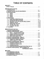
TABLE OF CONTENTS
E SAFETY
SAFETY RULES “ccc cc ctv iit eee tee eee ieee
HOPERATOR’S STATION
1. INTRODUCTION ooo cocoa.
2. DESCRIPTION OF MAJOR EQUIPMENTS- ..................ereecee..
3. SPECIFICATIONS
3-41. UR503 -........ee..r0ececc0a0000 oa aaaaoaaroaoaa0oo anno
3-2. UR504 1. LL LL a aa
3-3. UR505 --............e0ererrerecreeraaearaaecocaaocia, 00,0.
3-4. UR506 -.............e00000 0080000 ena aa aa a aan
4, OPERATIONS
. CONTROLS IDENTIFICATION --.................0000000000e.
‚ OPERATING INSTRUCTIONS cc
. MAXIMUM LOAD AND BOOM ANGLE CHART ---.--...---. E
. GENERAL RULES --...........00000000000eoooa a aoooaaoacoa
. OPERATING THE UNIT --.........200000000000 00 ao ooo.
. LIETING THE LOAD -..........0000000 oa aoo a ano
ROADING THE UNIT -.........200000 0 aaooaooaaooaooo o
5, PLACARDS ee aaa
!
y PRERERAR|
NOGRON A
HMAINTENANCE SECTION
1. PERIODIC MAINTENANCE -..............….…...22 LL a aaaaooaoooace
2. PERIODIC MAINTENANCE / DAILY
2-1. WALK — AROUND INSPECTION-..........…...….….…..…..….….…..….….….….…..
2-2. CHECK HYDRAULIC OIL LEVEL
2-3. INSPECTION FOR FUNCTION --...............00.00000 0... cee
2-4. WIRE ROPE INSPECTION --.........eeressororoc0a00 ae
3. PERIODIC MAINTENANCE / WEEKLY --..............00000000r000e..
4. PERIODIC MAINTENANCE / MONTHLY
4-1. LUBRICATE SWING BEARING ---.........eee0000000rericc ee...
4-2. CHECK GEAR OlL LEVEL e ao
5. PERIODIC MAINTENANCE / ANNUAL
5-1. CHANGE HYDRAULIC OIL --..........e.e00eroooeorecorenaeoeeo.
5-2. CHANGE RETURN FILTER - (еек ккв кв веккаие
5-3. CHANGE GEAR OIL ................000000800r0co0o arce
5-4. CHECKING SWING BEARING MOUNTING BOLTS ---...........
6. PERIODIC MAINTENANCE / REPLACEMENT OF
EXPENDABLE PARTS ...........
HOTHERS
1. RECOMMENDED GREASE: .....e...eeereorccorecoo.orococacrrearacoao
2. RECOMMENDED GEAR OIL -...........eeeecsecosocacocoredrecacoa..
3. RECOMMENDED HYDRAULIC OIL -..............e....ec00000arcore.
4. HYDRAULIC CIRCUIT --..................0000sr000arcre.oororeceecaoeo
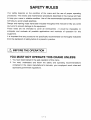
E SAFETY
SAFETY RULES
Your safety depends on the condition of the crane and the use of proper operating
procedures. The checks and maintenance procedures described in this manual will help
to keep your crane in reliable condition. Use of the recommended operating procedures
will help you avoid unsafe practices.
Danger and warning notes have been included throughout this manual to help you avoid
injury and to prevent damage to the equipment.
These notes are not intended to cover all eventualities ; It would be impossible to
anticipate and evaluate all possible applications and methods of operation for this
equipment.
It is important that any procedure not specifically recommended be thoroughly evaluated
from the standpoint of safety before it is placed in practice.
/N BEFORE THE OPERATION
YOU MUST NOT OPERATE THIS CRANE UNLESS:
1. You have been trained in the safe operation of this crane.
2. You read, understand and follow the safety and operating recommendations
contained in the crane manufacturer's manuals, your employer's work rules and
applicable government regulations.
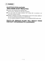
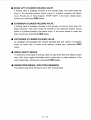
/N DANGER
ELECTROCUTION HAZARD
THIS CRANE 1S NOT INSULATED.
O Maintain safe clearances from electrical lines.
Allow for boom, electrical line, and load line swaying.
O This crane does not provide protection from contact with or proximity to an
electrically charged conductor.
O Maintain a clearance of at least 10 feet between any part of the crane, loadline or
load and any electrical line carrying up to 50,000 volts.
One foot additional clearance is required for every additional 30,000 volts or less.
DEATH OR SERIOUS INJURY WILL RESULT FROM
CONTACT OR INADEQUATE CLEARANCE.
/N WARNING
FAILURE TO OBEY THE FOLLOWING CAN RESULT
IN DEATH OR SERIOUS INJURY.
O Do not operate any outrigger unless you or a signal person can see that all
personnel are clear of the outrigger and its ground contact point.
For crane stability use only solid, level surface with outriggers properly extended.
Crane must be level.
Operate all controls slowly and smoothly.
Never operate the crane with personnel under boom or load.
Keep at least 3 wraps of loadline on winch drum.
Do not overload.
Always know your operating radius, and the actual weight of load being lifted.
@® Never hoist personnel on hook, load or any device attached to loadline.
O For travel, boom and outriggers must be in stowed position.
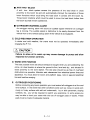
/N CAUTION
O Inspect vehicle and crane including operation, prior to use daily.
O Failure to allow oil to warm up may cause damage to pump and slow response to
function controls.
@® Payout loadline before extending or lowering boom.
O When operating unit, keep boom clear of overhead obstructions.
O Keep load under boom tip.
Do not side load boom or drag loads.
Avoid free swinging loads.
Disengage P.T.O. before driving truck.
Do not modify or alter this crane without written UNIC factory approval.
Use only UNIC approved or factory supplied attachments or spare parts on this
crane.
O Crane must be mounted on factory recommended chassis. If remounted or rebuilt,
the crane must be recertified.
E OPERATOR'S STATION
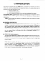
1. INTRODUCTION
This manual is furnished with your UNIC crane. Its purpose is to acquaint you with the
safety rules, operating characteristics and equipment checks. To properly utilize the full
potential of your crane, we feel you must:
1. Observe all safety rules.
2. Understand the equipment.
3. Do not operate this crane until you read and understand this manual.
FURUKAWA UNIC CORPORATION cranes are manufactured in accordance with the
applicable portions of OSHA regulation, #1910.180 and 1926.550 as in effect at date of
manufacture,
Note: OSHA prohibits the alteration or modification of this crane without the written
factory approval.
Ш GENERAL DESCRIPTION
The UNIC crane is hydraulically powered and consists of a base with outriggers. Each
outrigger is independently controlled and has double acting cylinders to actuate its
legs. A hydraulic motor, driven through worm gear assembly, powers the rotating bull
gear attached to the turntable. The units are equipped with dual control stations, hoist
winch, and multistage extending boom assembly. The power source is provided by
the truck engine driving the hydraulic pump with a transmission mounted P.T.O.
(Power- Take- Off).
EH OPERATOR RESPONSIBILITY
You are the key safety factor in achieving good performance and long life of the unit.
Even though you may be experienced in crane operations, you must read, understand
and follow the instructions in this manual. Learn to operate the unit in a safe and
efficient manner.
If the crane is supplied with optional equipment, read and understand additional
instructions supplied by FURUKAWA UNIC CORPORATION or the authorized
dealer. Questions concerning application, operating procedures or maintenance
should be directed to the TOMEN AMERICA INC., ATLANTA OFFICE, GWINNETT
PARK, 4295- A INTERNATIONAL BLVD., NORCROSS, GA 30093.
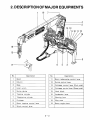
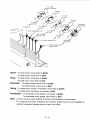
2.DESCRIPTIONOFMAJOR EQUIPMENTS
m 0
18—
e
17
No. Description No. Description
1 Boom 11 Boom telescoping control lever
2 | Column 12 | Swing control lever
3 | Base 13 | Outrigger control lever (Curb side)
4 | Hoist winch 14 | Outrigger control lever (Street side)
5 Swing device 15 | Hook block
6 | Topping cylinder 16 | Accelerator lever
7 Telescoping cylinder 17 | Warning horn
8 Outrigger 18 | Wire rope
9 Boom topping control lever 19 | Boom angle chart
10 | Winch control lever
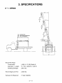
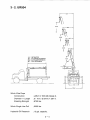
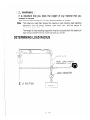
3. SPECIFICATIONS
3-1. UR503
4'———>
32.3’
| 4.5" ———
y
10.8” RETRACTED 17.1
18.7' 2nd STAGE EXTENSION
26.5 FULL EXTENSION
1
Winch Wire Rope
Construction : (JIS) 6 x Fi (29) Grade B.
Diameter x Length ; 5/16 in. (8.0mm) X 223 ft.
Breaking Strength ; 8510 165.
Winch Single Line Pull ; 2000 Ibs.
Hydraulic Oil Reservoir ; 13 gal. capacity.
a | 1
| .
— o 4,
/ La NAL ) 4
“J Lars
ZZ
12.4
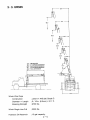
3-2. UR504
84 — >
—65-—
| 4.6' — >
26.9" 3rd STAGE EXTENSION
34.7 FULL EXTENSION
\/
9 \ \
11.2' RETRACTED |
19.1’ 2nd STAGE EXTENSION 17,5 \
Winch Wire Rope
Construction ; (JIS) 6 x WS (26) Grade C.
Diameter X Length ; 57/16 in. (8.0mm) X 267 ft.
Breaking Strength ; 9700 lbs.
Winch Single Line Pull ; 2000 lbs.
Hydraulic Oil Reservoir ; 13 gal. capacity.
2 — 4
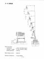
3-3. UR505
11.5" RETRACTED
19.3’ 2nd STAGE EXTENSION
27.2' 3rd STAGE EXTENSION
35.1' 4th STAGE EXTENSION
42.9' FULL EXTENSION
—
= =——
| —
—
: (JIS) 6 x WS (26) Grade C.
5/16 in. (8.0mm) X 311 ft.
Winch Wire Rope
Construction
Diameter X Length
Breaking Strength ‚ 9700 165.
Winch Single Line Pull : 2000 165.
Hydraulic Oil Reservoir : 13 gal. capacity.
2 — 5
3-4. UR506
121 — — — —>
10,3 — —m—
56.5' E
6.6’ ——
4.7 — >
12.7 RETRACTED
20.5’ 2nd STAGE EXTENSION
28.4" 3rd STAGE EXTENSION
36.0 4th STAGE EXTENSION
43.7" 5th STAGE EXTENSION
51.3" FULL EXTENSION
Winch Wire Rope
Construction , (JIS) 6 X WS (26) Grade C.
Diameter X Length ;5/16 in. (8.0mm) x 295 ft.
Breaking Strength ; 9700 lbs.
Winch Single Line Pull ; 2000 Ibs.
Hydraulic Oil Reservoir ; 13 gal. capacity.
2-6
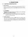
4. OPERATIONS
4-1. CONTROLS IDENTIFICATION
A. CAB CONTROLS
The P.T.O. / pump contro! is located within the driver's reach. The P.T.O. is
engaged when the knob is moved up and disengaged when the knob is moved in.
The truck gear shift must be in the neutral position when the P.T.O. is to be
engaged.
/\ CAUTION
Disengage P.T.O. before driving truck. Failure to do so will cause
damage to the transmission and pump.
Note; The park brake must be firmly set before leaving the cab to begin operation.
If the ground surface is icy, slick or sloped, you will be required to help
stabilize the truck with wheel chocks.
B. CRANE CONTROLS
With the dual operator control station the UNIC CRANE can be operated on either
side of the unit. The controls on the base are ; boom raise, hoist, telescope and
boom swing, engine accelerator and outrigger system. Ali controls and direction of
actuation for desired movement are identified by the information placard mounted
on knob of the control lever.
To rotate
counter- clockwise
<A To extend
boom
To lower
| | hook
> <A To lower
boom
To rotate
clockwise Accelerator
7 | Low speed
Swing lever To retract
boom |
—— 7
Boom telescoping lever To hoist
7 hook
VÁ Hook mot
DA lever To raise
Va A boom
y «Boom topping lever Accelerator
High speed
Manual acceterator 7,
ON control lever
AH A
Boom: To lower boom, move lever to push;
To raise boom, move lever to pull.
Hoist: To lower hook, move lever to push;
To hoist hook, move lever to pull.
Extension: To extend boom, move lever to push;
To retract boom, move lever to pull.
Swing: To rotate boom counter- clockwise, move lever to push;
To rotate boom clockwise, move lever to pull.
Accelerator: To decelerate pump speed, move lever to push:
To accelerate pump speed, move lever to pull.
Note: Controls must be used together to achieve combinations of movements.
For instance, the boom extension and loadline (hoist) must be used together to
maintain clearance between boom tip and hook block.
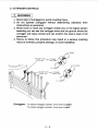
C. OUTRIGGER CONTROLS
/N WARNING
1. Stand clear of outriggers to avoid crushing injury.
2. Do not operate outriggers without determining clearance from
obstructions or personnel.
3. Never lower or raise any outrigger unless you or the signal person
assisting you can see the outrigger shoe and the ground where the
outrigger will make contact and can confirm the area is clear of all
personnel.
4. Failure to follow this procedure may result in a serious crushing
injury to workmen, property damage, or crane instability.
To extend
Outrigger lever Outrigger
(Curb side) = (Curb side)
To extend
To retract
Outrigger lever Outrigger
(Street side) (Street side)
To retract
Outriggers: To extend outrigger cylinder, move lever to push:
To retract outrigger cylinder, move lever to pull.
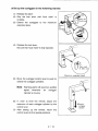
Xx Set up the outriggers in the following manner.
(6)
Release the latch.
Grip the lock lever until “blue mark” is
invisible.
Extend the outriggers to the maximum
extended state.
Release the lock lever.
Be sure that “blue mark” is fully exposed.
Move the outrigger control lever to push to
extend the outrigger cylinders.
Note: Warning alarm will sound an audible
sighal whenever an outrigger
cylinder is moving.
In order to level the vehicle, adjust the
extension of each outrigger cylinder by the
control lever. |
(7) After setting up the vehicle, return the
control levers to the neutral positions.
2 — 10
oA
Extend
the
outrigge
®
>i
\ Blue mark
is fully out
®Extend
outrigger
cylinder
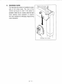
D. WARNING HORN
The warning horn switch is installed to each
side of the crane body. The horn of the
vehicle will sound to warn if the switch is
pressed. Warn the co- worker near the load
when starting crane operation or anyone
who has entered the swinging range during
crane operation.
2 — 11
/
©
Y
Warning horn switch
4-2. OPERATING INSTRUCTIONS
A. TRAINING
It is extremely important that you have a thorough knowledge of all the operating
characteristics of your crane.
This crane will not be safe if improperly used !
B. SAFETY DEVICES
Certain safety devices on your UNIC crane are described below. These devices will
help to maintain control of a load should power or hydraulic line failure occur. You
must understand the function and operation of these devices so that a continual
check on their performance can be made.
/N WARNING
YOU MUST NOT OPERATE THIS CRANE UNLESS:
1. You have been trained in the safe operation of this crane.
2. You read, understand and follow the safety and operating
recommendations contained in the crane manufacturer's manuals,
your employer's work rules and applicable government regulations.
/N CAUTION
Should any of these devices fail to function, stop all operations and
consult your authorized UNIC dealer.
This crane can be overloaded by an operator who fails to follow the
instructions contained in this manual.
2 — 12
Hl BOOM LIFT CYLINDER HOLDING VALVE
A holding valve is subplate mounted to the cylinder base. This valve holds the
boom in the elevated position should power or hydraulic pressure line failure
occur. Should any of these happen, “STOP NOW". If the boom creeps down,
consult your authorized UNIC dealer.
Hl EXTENSION CYLINDER HOLDING VALVE
A holding valve is subplate mounted to the cylinder rod end for more than 2nd
stage extension. This valve holds the cylinder in the extended position should
power or hydraulic pressure line failure occur. If the boom creeps in under the
load, consult your authorized UNIC dealer.
EH OUTRIGGER CYLINDER HOLDING VALVE
All outriggers are equipped with internal cartridge type lock valves. If outriggers
creep up under load, or down while roading, consult your authorized UNIC
dealer.
Ш WINCH SAFETY BRAKE
To determine if the brake is working, raise the load a few feet and release control
lever. Shut truck engine off;Actuate winch control lever in down direction. If the
load creeps down, consult your authorized UNIC dealer.
E SWING DRIVE BRAKE (ROTATION GEARBOX)
The rotation gear drive will have a worm self-locking brake.
2-13
E ANTI TWO- BLOCK
A anti- two- block system senses the presence of the load block in close
proximity to the boom tip and will automatically interrupt the operation of those
boom functions which could bring the load block in contact with the boom tip.
Those boom functions which could be used to move the load block further from
the boom tip shall remain operational.
EN OUTRIGGER WARNING ALARM
An outrigger warning alarm will sound an audible signal whenever an outrigger
leg is moving. The audible signal is distinctive to be easily discerned from the
vehicle horn or the vehicle backup alarm if the vehicle is so equipped.
C. COLD WEATHER OPERATION
In winter and cold weather, the crane must not be operated immediately after
engaging the P.T.O.
| /\ CAUTION
Failure to allow oil to warm up may cause damage to pump and slow
response to function controls.
D. WORK SITE POSITION
The best possible work site should always be sought when you are positioning the
crane. An ideal location is where the ground is firm, level and dry, and situated in
close proximity to the work station. The site also should be as free of overhead
obstructions as possible. Maintain safe clearances from electrical power lines and
apparatus. You must allow for boom and platform sway, rock or sag and electrical
line and loadline swaying.
E. OUTRIGGER POSITIONING
Before conducting any boom operation you must extend all outriggers to a firm and
level surface. In the event that other conditions exist such as: loose or sandy soil;
crusty or frosty surface with soft soil underneath; icy or slick pavement; sloping
surfaces, etc., you will be required to restrict you operations. In some areas you
may be able to level your crane with the use of outrigger pads or blocks. These
pads must be made of adequate material.
2—14
F. LOAD HANDLING OPERATIONS
Before moving a load, you must study the capacity placards carefully and adhere to
the load capacities and radii of operation given. The information provided on this
load chart is based on 85 % of tipping. During operations when lifting, swinging, or
extending the load the controls should always be metered when beginning or
terminating movement to prevent sudden starting or stopping which imposes undue
shock loads on the equipment. This is especially true when handling heavy loads.
The controls should be metered to begin slow continuous movement, then slowly
increased to desired operating speed.
Never hold a control lever in the open position after the function has reached the
end of its travel. This will impose unnecessary stresses on the components, reduce
service life, and generate heat in the hydraulic oil.
2-15
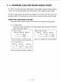
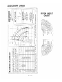
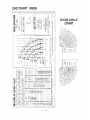
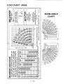
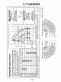
4-3. MAXIMUM LOAD AND BOOM ANGLE CHART
The maximum load charts shown are located on the operator console. Their purpose is
to show you the load capacities at the various radii or boom angle and hook heights.
The boom angle charts also shown are located on the base boom just above the
operators station. Their purpose is to show the boom angle and radii at various points.
OPERATING CONDITIONS OF BOOMS
The booms start to extend with the outer boom and to retract with the top boom.
(1) 3- section boom.
The booms (2) and (3) extend in the order stated, and the booms (3) and (2)
retract in the order stated.
All booms retracted : Second stage extended :
Boom (1) Boom (2) Boom (3) Boom (1) Boom (2) Boom (3)
| NN
Booms (2) and (3) are completely retracted Boom (2) is extended with boom (3) retracted
Third stage extended:
Boom (1) Boom (2) Boom (3)
WN NW в
Yah
Booms (2) and (3) are completely extended
2-16
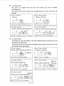
(2) 4- section boom.
The boom (2) extends first and then the booms (3) and (4) extend
simultaneously.
The booms (4) and (3) retract first simultaneously and then the boom (2)
retracts.
All booms retracted : Second stage extended:
— Boom (1) Boom (1) Boom (2)
| TX ' а
All booms are completely retacted in boom (1) Boom (2) only is extended
Third stage extended : Fourth stage extended:
Boom (1) Boom (2) Boom (3) Boom (4) Boom (1) Boom (2) Boom (3) Boom (4)
Boom (3) is extended as far as “4 mark Booms (3) and (4) are all extended
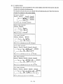
(3) 5- section boom.
The booms (2) and (3) extend in the order stated and then the booms (4) and
(5) extend simultaneously.
The booms (5) and (4) retract first simultaneously and then the booms (3) and
(2) retracts in the order stated.
All booms retracted : Second stage extended :
Boom (1) Boom (2) Boom (3) Boom (4) Boom (1) Boom (2)
Boom (5)
All booms are completely retacted Boom (2) only is extended
Third stage extended : Fourth stage extended:
Boom (4)
Boom (1) Boom (2) Boom (3)
Boom (1) Boom (2) Boom (3)
Booms (2) and (3) are extended Boom (4) is extended as far as “\ "mark
Fifth stage extended :
Boom (5)
Boom (1) Boom (2) Boom (3) Boom (4)
—
Booms (4) and (5) are all extended
2-17
(4) 6- section boom.
The booms (2) and (3) extend in the order stated and then the booms (4) and
(6) and (6) extend simultaneously.
The booms (6) and (5) and (4) retract first simultaneously and then the booms
(3) and (2) retracts in the order stated.
All booms retracted :
Boom(1) Boom(2) Boom(3) Boom(4)
Boom(5)
Boom(6)
All booms are completely retacted
Second stage extended :
Boom(1) Boom(2)
Ru
| N
Boom (2) only is extended
Third stage extended :
Boom(1) -Boom(2) Boom(3)
Boom (3) is extended as far as “ \ "mark
Fourth stage extended:
Boom(1) Boom(2) Boom(3) Boom(4) Boom(5)
М _ A Boom(6)
DER
Boom (4) is extended as far as 1st “N"mark
Fifth stage extended :
Воот(1) Boom(2) Boom(3) Boom(4) Boom(5)
\ _ \ Boom(6)
CEE
Boom (4) is extended as far as 2nd “\ "mark
Sixth stage extended :
Boom(1) Boom(2) Boom(3) Boom(4) Boom(5)
Boom(6)
Pata
\ VA 7
Booms (4),(5) and (6) are all extended
2—18
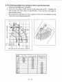
Xx The following example is an example of how to use the load chart.
1. Extend the 3rd stage boom completely.
2. Using the boom angle indicator as your guide, raise boom to 60° elevation. As
can be seen, the boom radius is approximately 14 feet and the hook height is
approximately 29 feet.
By looking at the load chart, the boom capacity is 5100 Lbs. This capacity must be
reduced for some optional equipment.
40
35 /
ias
/ 40°
25 A > N BOOM ANGLE
20
AX
HEIGHT IN FEET FROM GROUND
—
OT
ma
——
—
nn
—
pm
in
ST mr mo Y —3RD
—
| A <n |
Y ROTATION Y y |
Г 5 10 15 20 25/ 25
(2.7) (26.5)
BOOM RADIUS IN FEET FROM CENTER OF ROTATION
BOOM
En ALL BOOMS RETRACTED | SECOND STAGE EXTENDED { THIRD STAGE EXTENDED
(LBS.) (LBS.) (LBS.)
7 10,000 10,000
7.7 10,000 10,000
9 8,500 8,500
10.5 7,200 7,200 6,700
11 6,900 6,700
12 6,300 6,300
14 5,100 5,100
16 4,400 4,400
18.5 3,700 3,700
20 3,400
22 | 3,100
24 —. 2,800
| 26.5 2,600
2 — 19
/N WARNING
lt is important that you know the weight of any material that you
attempt to handle.
This can be determined by use of a dynamometer or scales.
Note: The maximum load chart shows the maximum load including load handling
equipment such as slings, buckets, hook block, etc., and the weight of
material being handled.
The weight of load handling equipment must be deducted from the maximum
load rating to determine how much pay load you can lift.
DETERMINING LOAD RADIUS
LOAD LINE
Da
READ LOAD RADIUS
DIMENSION ©
@ of ROTATION
WEIGHT
LOAD CHART UR503
2945 JH
15415 OME
ul
—
(5 q
E AE |6!
2 (С ñ 8 eu ve e A || NLS PSI
< J кс» De o “VT 4ISW31 A008
SI HS
/ QDD
O O ! / 2 o TION 3
a NEY SNIE 008
O 2 ~~ un | Са a 7
00 | IE Pure moog —=
- нон не. = - нк) не
“= La _o 0 | 07
29.5 03Е > a
a Ello E.Z,
LS 6 | 61 97, > > >
5915.5 || | / ry LE Op,
| HISK37 №008 : НН; 34 KE 2
: q N ,
| 0 £ Y : A \
© À Co
Te? | Ta
sniavy wood | es o
No A TA
ое |
PAV] О NOLLYTOIA V SI OHVOVY1Id SIHL 40 1YAOW1%
Er
JE MIVICNVIA JO 31YO 1 T9YINddY JUIIA
055 IZ6óL ANY OBL 0181 SNOLLYTÄOTE YV-ISQO НМ STINGS ЭКИОТА с!
Sgj0:58
HIDONIHLS ON {HY3HE NONININ
FNIHOVH SIHL NO
JdOY JHlAA YILSNVIO
9 1/G ATNC 3SM
SIWIEL TV LV
WHO NO 3NI1dYC
d0 SdysM E
1SY411Y d33H
NOILNVOYŸ
A Lv A
Ou.
SANNOd NI L411 XYW
DNiA3Z6 NV 3d0d
^^
O
IE
IMIS
NY JY OAHOL
‘a1 709 VAMAVANEHNIA
NOISIAIA JINN
NONLYI0Y 20 631839 WOYJ 1:34 Ni SM:CYH YIDOS
‘5 92)
Se — Se nz Gi О. 5
I т
| h
a DC
— Lom
Fade | ane pr SEY |
1
‚Е — А |)
| —
7 = ci
INNOS9 WORT 1334 Ni LASA
009 € 582
0092 Fe
DOL'E zz
00P'E€ oz
00Z'€ 007€ Sel
0obr cob b | 91
001'S DOI'S | El
00€'9 00E'9 zl
00/9 0069 Li
0079 002 4 co7 / COL
005 8 cos 8 6
00001 000/01 EL
00001 000 D! /
sE E (STD |
азакара 39VLS OWL | 304303 79915 0NCO3S | AIOYHILEE SAOCE TV | (13)
A A @ и спим
E A 18 4 АЙ DE EZ. | 008
1511 NYD NOR OVOTAYd HODN AMOH FNINHILIO
OL DNILYH ато О МПИ Моня Odal9ndad 39 LSNW
INIFWdINO] ONITONYH QOYVOT JHE 40 LHOIAM ZH1 Q310OHVH
ONIES СММ +0 1H9I3M ЭНГ СМУ OL] SHIO1G
MOOH S13Y42n18 SONIIS SV HONS INNdINOS DNITONVH
OVYOT DNIQGNTONI aval WNWIXYAR IHL SMOHS LEUVHO SIHL
LHVHO OVOT NAOWNIXVIN
©)
©
2-21
LOAD CHART UR504
md Tp =P | Nr | GE
(5 FH 30825 ME | MIE | !
< СС 19% 15 ON? SN le:
< 19415 1SI ENVIOS |
= L | «19H37 A3 |
O O PAY Y ||
О ПО ОРКОВ
Or -
REE MT SO NOLVIOLA Y Sl dYYOY1d SIH1 40 1VYACH3Y on CWO JD dowd WD EEO devo HA
GGT OGRA LD ANY COL CIO SNIE VISO LAS SOI RADO GAMEZ SIR
997 015'2 NO YO 10 EILNIO WOCHE 1774 M SNIOYHE ADON 005 1 _ LPL
TS Dur y 00: | |
H15N5H1S ONMYIYE AMMINTA а) OS | =
FNIHOYIN STHL NO Soo : 1 ; i 000 € OOt'€ Le
IdOr: AA HI SWIC | HOLLWLOM a 002 2 0097 a Ge | |
JS ATNO SM la -—] 00+ 2 0067 Eo
mt 0092 008€ | 12
SIN TI IV 006€ 009€ DOS E — 61
N°0 NO INIOVO 901€ 0085 | DOS E В! |
10 Savgm € 005€ | 00PF_ DOF E 91 |
1SYl 1Y dla г 001 Y 001% | 001 5 ti
ет 00S‘+ 004'S 007 5 El
| | v © 00S + 0029 006 J 006 © LL
NOILNVO — = E | 005 B DOS @ 6
Ш | < | 090 01 00001 21
A PE A и, | | ©9991 | 09001 /
(arr! pe i : SAL (3580 Is) ofr)
o И > т CONT ЕЛ 470 | GRINDS J.E Dae FINI Bs SAT позы. ЗЫ 5АСОЯ Г
SATS 2 ffs 3 as 8 SS | AY
. Вы _ © АН NYOI NOA AY OTA Vd HINA MOH 3NINEH139
SANNCA NI L411 КМА © OL DNILVH OvOl WNWXYW WoHY 03190034 39 ISA
INIA338 ONY 4404 о INIWNGdINO3 ONITONVH dYO1 3H1 40 1HDI3M 3HL O310NVH
© - ЭМО IVISILYW 49 1HDIDM Ski CNY “13 'SHOOTS
| bn MOOH 'SIIMONA SONINS SV HONS INZWAINO] ONNONYH
NYdYT “OAXOIL | | | О) VU | | OYOT DNIONTON! OVOT HONIXYN JH1 SMOHS LUVHO SIFI
ALT 09 YMWHONHO | | но Fis i г | a o a ma mm Nm E
— NOISIAIG OINA 12 ldVH3 avO1 NNNIXYIN
(où A = a 01 a en a M
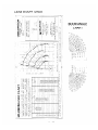
LOAD CHART UR505
р
>. HAN
0)
Lu TE
о o ge
1 VIS ANS NLS HIS | € F FA Ue
23915 Al SYS Hy | ms
О se go
1291S CHE Юм, Out -
< СС eZ
; IIS OME 29715 242 in N
< / В 07 y
= IT LA MIS LS. | 30WIS 151 x
О O A / НИ” бов 419851 7008 <? \
| J ! _ Ta
j = | 3197 7 | 3 NY % DS
O 3 — | ЗП АСЕ SACYH MODE O
O IT 10 No J So À ai !
| HUN wes RAEE EZ E a Te AOE \
O Oz
CEOLEBYET с THO LOW ATHY 40 LYC 4 37992 dd ЭНН
| | CIA | | TYACWIY
MT AO NOTEVTOU VS QEVOIY ld SIHL 40 CSS 9261 ONY 081 CIS SNONLVICIIH Y:150 LIM SIN AOS INEA SIE
, 42 | = LOAN 004 Sch
Sa oLS'e | NCILYLCH JC Y21%29 WOH4 21333 М SN dYye A008 соб =
HLONIHLS DNIMVY IHG WITAINIAL 6 2p] > 0001 pos | GE
ANIHIYW SIHL NO Sp ; cr ce > gy 51 il с 5 ” 0 00% | 007 1 ct
4404 SHIM daLanNvia 008 | 006 | | 62
91/5 AMINO 3SN 00€ | 000 € COE ¢ Hz
| DOS 00? г 0082 EZ
a | Dog 006 € 00b'E 00YE 56}
| ЭЗАЦ 1 F7 LV [ 000€ DOTE 007 E 007 E gi
XAO NO aNTIOVO | | odez DOS E 002 002 © at
40 SdvHM & | ooe'e DOF 006 + 006 Y ki
15YI1 1Y d394 DOS + 00€ S 00€ 5 El
ee] 00S 00€ 9 00€ 9 00€ 9 Ski
NOILNVYOY 0045 00€ B co a 6
B | 009 002 65 00е 6 8
| i 1? Wo = 00001 DEJO pa
4 jHvd € DOM F005 X _ г | | | 000 Ol 009 Ol a
AN tk] (591) san | SON {san SO)
COCO Aral AGAN XI O3ONAIX 3 AINE GIONS O3 LOWHLSE qe)
a - q _ 7 SOVYIS HIS P35%S HIECC of] SES OM GLS TIES ENCOS TW ; Pg
| u ! an D - | _ SUE
\ A : < ÉS бо) ac $ pu 7 SU кров со TE NOUS
— TAE
SONNOd Ni LAIT ХММ S 1311 NYI ACA AYOTA Vd HINA MOH 3NINH139
E : HAT AJ * "o E
9N/AJ3H ANY 3dOH коб OL ONLY vol WOneW Wold a3londda 38 1SMA
_ iNSFWidi1103 DNUONYH CYCT 3Hi 50 1HDISA 3H1 OST1ONYH
| een 05 ЭМО УМНА НО LHOLAM AHL ANY "MI 'SM9019
11935 MOOH SiaHIÑNa 'SaNNS SY HONS INAMKIND3 SNIMONYH
NYdYr "OAHOL 55 YO SNIAMIINI OYO] WANIXYA FHL SACHS LHYHD SIHL
а под МММ —
NOISIAIA JINN | a 1НУНО AVOT WNNINIXYIN
OL _ o fo A
Nadi ma
©/
2 — 23
LOAD CHART UR506
BOOM ANGLE
CHART
~~
020182350
39V1S HIS
39Y1S HIS
39V1S Hb
39v1S QUE
39v1S ONZ
39VLS 1SI
010 189380
39V1S (№
JOVIS 18
‚ Н19№71 №008
HION31 W008
TONY % JIONV ®
SAIGYH №008 SNIGVY NOO8
o) O ©
0£0180380 . JYNLIYINNYW 40 31Yva Lv I19YJI 1ddY 3J3HM
МУП ЗО NOLLVTOIA V SI QYVIV Id SIHL 40 IVAOW3E OSS ‘9261 ONY 081 OL6i SNOILYINO]IH VYHSO HLIM S3IITJNOO 3NIHOYN SIHL
‘Sg1O01S‘8
HLONJELS ONIXVIHE NONININ
‘3NIHOVN SIHL NO
3404 IYIM HLINYVIa
«9 1/5 ANO 3SMA
S3WIL T1V LV
ИНО № 3NMavol
10 SdVvUM €
1SVv31 1V d33X%
NOILLANVI Y
SANNOJ NI 1317 XVI
OINIA394H ANY 3dOH
| USENNN
WAS
NVdVFr 'OANOL
‘all "02 YMYXNHN4
NOISIAIG JINN
QO
NOILVLOY JO d31N30 NOdd 1334 NI SNidvd W008
GS
(409)
ay
Ov
cx xn AS
Hib
0]
(82)
q
1S 13
0
104
se
0€
S£
07
Sy
05
ANNOY9 WOHJ 1334 NI 1HOI3H
55
08
59
2 — 24
00€ 06
00% 00. 627
005 006 6€
00S 0001 00S | SE
009 001! 0071 ce
009 007 | 006 | 67
002 00€ '| 000 € 00€ 2 Ss
006 005 1 007 7 008 г EC
0011 008 | 006 7 007 € 007 € El
0011 000 ¿ 001 € 002€ 002 € gl
00£ 2 00S € 007 Y 007 Y 91
005 с 001 Y 006 Y 006 Y vi
00S y 00£ S 00€ S £l
005 $ 00€ 9 00£ 9 00€ 9 Si
007 9 000'8 000'8 6
0072 9 000 8 000 8 8
000'8 000'8 LAA
000 8 000'8 Z
(697) (sg {sat (697). {sat (sa)
ada | ada | adas | ada | озамама À œuovaiay | (u
30viS HIXIs | æovishzds | 29iSHiEMOs | 30viSQMML | 39Y1SNDOSs | swooeTv | sSNIOVH
Sper ha V ha | hoaaV | hr Coo №08
14 NVO NOA AVOTAVd HONW MOH 3NIWH3130
OL ONILVH OVOIT WNAWNIXVN NOB4 d31oNnd3a 38 ISAAN
LNAWdIND3 INMANYH AYO! 3HI 40 LHDIJM 3HL "OSTONVH
MOOH “S13M5Ng SONMS SY HONS 1N3WdIND3 ЭМПамун
QVOT DNIONIONI OVOT NANIXVN 3HL SMOHS IEVHO SIHL
ONIF9 IVIJILYN JO 1HDI3M 3HL CNV 013 SYHIOT9
14VHO OVOT NNANDOWWN
©
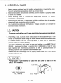
4- 4. GENERAL RULES
1. Always operate controls to lower the loadline while extending or lowering the boom.
This will maintain clearance between boom tip and hook block.
2. Make certain loadline is not twisted or kinked, and that loadline is properly seated
on drum and in sheave. |
3. During winching, meter all controls and apply power smoothly. No sudden
acceleration or deceleration.
4. When raising a load, raise it a few inches and allow controls to return to neutral to
determine if brake on winch is working properly.
5. You must not make side pulls with the boom. This type of loading can damage the
boom and rotation mechanism.
/N\ CAUTION
The boom and loadline must form a straight line between boom and load.
6. When lifting a load, you must always make certain that three (3) full wraps of rope
remain on winch drum before raising the boom. Maintain tension on the loadline at
all times to prevent rope from becoming twisted or kinked and to keep cable
properly seated on drum and sheaves.
The proper maintenance and care of the wire rope loadline on your UNIC TRUCK
CRANE is most important. Refer to standard ANSI / ASME B30.5- 1982 for wire
rope inspection and maintenance procedures as well as special provisions for
handling maximum rated [oads with rotation resistant ropes.
Loadline loop and drum wedge must be properly seated inside winch drum before
winding loadline on drum.
/N CAUTION
Polypropylene rope must not be used with set screw to seat it on the
drum. Wire rope only.
GD
THREE WRAPS MINIMUM
ALL WINCHES Drum wedge
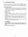
4-5. OPERATING THE UNIT
Now that you are familiar with the controls and function of the UNIC crane, practice
making some typical lifts. As with any piece of equipment, practice is required to
develop the coordination and knowledge necessary for smooth and efficient operation.
A. INITIATING OPERATION
1.
If possible, position the unit at the job site in such a manner as to assure all work
operations can be performed without repositioning the truck (see “work site
position”). However, strict observance of load weight radius and maximum load
rating must always be complied with.
. Set brake securely.
. Engage PTO.
. Position wheel chocks.
Extend all outriggers to make firm contact with ground. (see “outrigger
positioning.”) Provide outrigger pads if terrain is soft or if outriggers tend to sink
into ground. |
Position yourself at the operator's console and accelerate the truck engine to
desired speed. Maximum pump speed should not exceed 2,000 R.P.M.
Bring the hydraulic oil up to operating temperature. (see “cold weather
operation.”)
Check all controls for proper operations. During all operations, the controls should
be metered to prevent sudden starting and stopping.
/N WARNING
Failure to meter your controls induces undue shock loads on the
equipment which may result in structural failure or overturning of the
crane.
Death or serious injury may result.
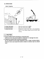
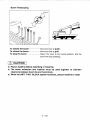
B. OPERATIONS
Boom Topping
To lower the boom ------------...- Move the control lever to push.
To raise the boom --------=-=--...- Move the control lever to pull.
To stop the boom >... Release the control lever, and it will automatically
return to the neutral position and the boom stop
moving.
/\ CAUTION
Xx Payout loadline before extending or lowering boom.
Failure to do so may cause loadline to break and / or damage the crane.
% Operate the control lever as slowly as possible.
Do not operate the lever jerkily especially when a cargo is being hoisted.
Failure to do so can cause the crane to break or overturn due to a shock
load.
Hook Hoisting and Lowering
To lower... Move the control lever to push.
To hoist:......….….…........ Move the control lever to pull.
TO Stop::--===e===...e.... Release the control lever, and it will return to the neutral
position and the mechanical automatic brake will be actuated
to stop hoisting or lowering the cargo.
/N CAUTION
x Do not keep lowering (paying out the wire rope) after the cargo (hook) has
landed on the ground.
Failure to do so can cause disordered windings of rope around the drum,
and shortening the service life.
x If the first layer is not properly wound on the drum, the wire rope may
easily stick in the gaps in the second and subsequent layers, causing
winding disorder.
Operate slowly and assure proper winding of the first layer on the drum.
N
|
28
Boom Telescoping
Extend
ол
ZA S
Retract
Ss
To extend the boom... Move the lever to push.
To retract the boom ------=----......- Move the lever to pull.
To stop the boom : Return the lever to the neutral position, and the
boom will stop operating.
/N CAUTION
x Payout loadline before extending or lowering.
x The boom extension and loadline must be used together to maintain
clearance between boom tip and hook block.
x When the ANTI- TWO- BLOCK system functions, payout loadline to reset.
Swing
Crockwise
swing
To rotate boom counter clockwise
ean Move the lever to push.
To rotate boom clockwise.........
Move the lever to pull.
To stop swinging ...............
Return the lever to the neutral position,
and the turntable will stop.
/N CAUTION
% Swing operations should be performed at
low speed without using the accelerator.
% Operate the control lever slowly so that
the crane starts and stops swinging
smoothly. Jerky lever operation can
cause the load to swing and bump
against the crane or the vehicle to turn
over.
% The longer the boom or the lower the
elevation of the boom, the faster the
swing speed of the load. Therefore, swing
the crane slowly.
% When swinging the boom over the front,
it may be necessary to raise the boom to
clear the cab.
Boom
E
Counter -
clockwise
swin
Е —
OVER
SIDE
CD 7 6
OVER
| REAR
CD ;
OVER
SIDE
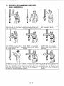
C. OPERATOR’S COMMUNICATION CHART
(ANSI / ASME B30.5)
HOIST. With forearm vertical, fore-
finger pointing up, move hand in
small horizontal circle.
LOWER. With arm extended down -
ward, forefinger pointing down,
move hand in small horizontal circle.
USE MAIN HOIST. Tap fist on head;
then use regular signals.
USE WHIPLINE (Auxiliary Hoist).
Tap elbow with one hand: then
use regular signals.
RAISE BOOM. Arm extended,
fingers closed, thumb pointing
upward.
LOWER BOOM. Arm extended,
fingers closed, thumb pointing
downward. |
MOVE SLOWLY. Use one hand to
give any motion signal and place
other hand motionless in front of
hand giving the motion signal.
(Hoist slowly shown as example.)
RAISE THE BOOM AND LOWER THE
LOAD. With arm extended, thumb
pointing up, flex fingers in and out
as long as load movement is
desired.
LOWER THE BOOM AND RAISE THE
LOAD. With arm extended, thumb
pointing down, flex fingers in and
out as long as load movement is
desired.
SWING. Arm extended, point with
finger in direction of swing of
boom.
STOP. Arm extended, palm down,
move arm back and forth
horizontally.
EMERGENCY STOP. Both arms
extended, palms down, move arms
back and forth horizontally.
TRAVEL. Arm extended forward,
hand open and slightly raised,make
DOG EVERYTHING. Clasp hands in
front of body.
TRAVEL (Both Tracks). Use both
fists in front of body, making a cir-
cular motion about each other, indi-
cating direction of travel, forward or
backward. (For land cranes only.)
pushing motion in direction of travel.
TRAVEL.(One Track)Lock the track
on side indicated by raised fist.
Travel opposite track in direction
indicated by circular motion of
other fist, rotated vertically in front
of body. (For land cranes only.)
Booms).Both fists in front of
body with thumbs pointing
outward.
RETRACT BOOM (Telescoping
Booms).Both fists in front of
body with thumbs pointing toward
each other. |
EXTEND BOOM (Telescoping
Boom). One Hand Signal. One fist
in front of chest with thumb
tapping chest.
\
RETRACT BOOM (Telescoping
Boom). One Hand Signal. One fist in
front of chest, thumb pointing out-
ward and heel of fist tapping chest.
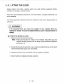
4-6. LIFTING THE LOAD
Always inspect hook block, loadline, and/or any load handling equipment before
operation for damage or excessive wear.
Follow the recommended procedures for work site position, outrigger positioning, and
control metering.
The following general instructions should be adhered to each time a lifting operation is
performed.
/N WARNING
lt is important that you know the weight of any material that you
attempt to handle. This can be determined by use of a dynamometer or
scales.
Ш STEPS TO LIFTING A LOAD
1. Determine what the total load weighs.
Note: Total load includes the weight of the material being lifted plus any
material handling devices such as slings, yokes personnel platforms,
load blocks, etc. | |
2. Consult the maximum load chart on your crane and determine the correct boom
radius aliowed based uppon your load weight.
3. Rotate the boom tip until it is directly over the material to be lifted.
4. Attach loadline to material and begin operation.
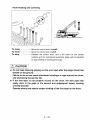
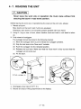
4-7. ROADING THE UNIT
/N CAUTION
Never leave the work site or reposition the truck crane without first
securing the boom in road travel position.
Before leaving the work site or repositioning the crane at the work site, always:
1. Retract all boom.
Stow booms on the boom rest if unit is so equipped.
Otherwise, stow booms in a horizontal position parallel with truck frame.
2. Using D-ring on rear of truck, attach loadline hook and hoist in until slack is taken
up.
3. Fully retract all outriggers.
The outrigger should be stored in the following manner.
(1) Move the outrigger lever to pull to retract the outrigger cylinders.
(2) Grip the lock lever to be “blue mark” invisible.
(3) Push the outrigger into the retracted position.
(4) Release the lock lever. Make sure that the “blue mark” is fully out and that the
outrigger will not come out.
(5) Fix the latch.
NW |
® Push outrigger in.
DRetract outrigger
cylinder
4. Disengage power take off (P.T.O.).
5. Secure any load or lifting attachments to the flatbed.
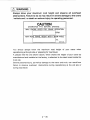
/N WARNING
Always know your maximum road height and observe all overhead
obstructions. Failure to do so may result in severe damage to the crane
/ vehicle and / or death or serious injury to operating personnel.
| CAUTION |
DISENGAGE PTO BEFORE DRIVING
MAX ENGINE SPEED FOR CRANE OPERATION
RPM
MAX ROAD TRAVEL HEIGHT WITH 1" BOOM ANGLE
FT.
088F81080
You should always know the maximum road height of your crane when
repositioning at the job site or preparing for road travel.
A placard like the one shown above, which shows the height of your crane as
manufactured and installed at the factory, is attached to the dash board inside the
truck cab.
Severe personal injury, as well as damage to the crane and truck, can result from
failure to observe overhead obstructions during repositioning at the job site or
during road travel.
5. PLACARDS
Z ‘@JOSUON 10381800
‘Heyl peo] "Xen
| ‘eseq woog ‘HT 8|buy woog
r
1
JIONV Y
$ПЮУН №08
| ‘eseq woog ‘HY 8|buy woog
7
Oy
0E€0188V80
"MY 1 40 NOLLVIOIJA Y Si ds Y9V id SIHL 40 TVAOW3Y
O
FHNLOVANNVIA 40 31YQa 1V F18VOIlddV JHIHM
OSS '9¢61 ОМУ 081 0161 SNOILYINOIY VHSO HLIM S3idNOS 3NIHIYWN SIHL
O
NOISIAIG JINN
O
"San OLe'e NOLV104 JO Y31N39 WOYJ 1334 NI SAICVH WOO9 009'2 69g
| 008'Z ve
NINFA (997) (17)
HIL9N9IYIS DNIMV3IHE ИМ z [ee 0 er. a o 0016 zz
INIHOVIA SIHL NO | T 007 E ос
IdOY IUIM YILINVIA i i NOILv 10d DOTE DOTE Sar
9 1/S A1NO 3SMN ! => : YT 00 or
-SINLL TIV LV (YE 39v1S 151 Ш 00L'S 001'S vl
WNHG NO 3NKNAVOT | | 00€ 9 00€ 9 a
1SV31 LV d35X _ 00.9 002°, 002'Z Sol
Oo m 00S‘8 00S'8 6
NOI invo y 2 00001 00001 zz
\ \ — 00001 00001 Л
‚02 = (sab (sg) (Sa) |
> m O30NLX3 39Y.LS CUIHL GZ0NADG 39VIS ANDJ3S } OALOVULIU SNOOS TV с y Ly y
NX o = I ws wn Aw) I Y KW [woos
| NZ 5
TIONV №008 \\ / “ < "L411 NYO NOA QYOTAVYd HONW MOH 3NINYAL3A
| y / 3 OL DNILVH avOol WNWIXYIW WOH4 dalondad 39 1SAN
SAONNOd NI LAIT XVWN N S 1N3WNdIND3 DNMONVH OVOT 3HL 30 LHDIIM 3HL ‘OFTONVH
INIA34H ANY 3dOH LO © ONI39 IVIYILYW JO 1HDIIM IHL ANY 013 ‘SMOOT@
RENAN ‚ 08 MOOH ‘S1IMONG ‘SONS SY HONS I1N3WdIND3 оМПамун
| Iviuas ; OVOT DNIANIONI QVOT NNNIXVW 3HL SMOHS LHVHO SIHL
NVdVI “OAXOL
‘aL “09 YMYXNHN4 oy
LHEVHO OVOT NANIXVWN
©)
2 — 36
2 “ejosuog 101e.edo ‘suoijoniisul BuiresadQ
O
(O)
080 187780
‘Juswadse|dal 10} Jainjorjnuew
JOBJUOO “suero siyj wo buissiu aie sienuew J.
‘pelj,13091
oq ]Snu ouB1D ay} inge 10 pejunowal y “sISSeyo
popuauwlulo9e: Ñoje; uo pajunow aq isn aueld .
"OUPIO SIL LO SHEd eleds 10 sjuetu
-Yoene parddns Arojpey 10 peso.dde SINN ÁjJuo asn
eso:dde Aopej OINN
иедим JNOYIM SUelo SIU JAje 10 Ájpow jou OQ -
ona) Buiaup alojeq OLd eSeBuesig +
'speo| BUuIBUIMS 884) PIOAY
‘speo| Belp 10 wooq peo} apis jou og
"dn Woog 19pun peo|; doey +
'SUONONASGO
PE9UYJI3A0 JO JE3JD LICOG daay un Bunesedo usuM +
'шоод Buuamo| 10 Buipua)xe 21010G OUI}PROI INOAE d +
"SJONUOO UONOUN] 0) asuodsal mos pue dwnd o)
abewep osued Aew dn Lem 0) ¡o moje 0) ainjie +
'Átep esn 0) od
'uonesado Bulpnjoul sueso pue apiyosa jOedsu.
MY | 40 NOLVIOI Y SI 0HVYIY 1d SIH.L 30 1YAON3H
‘UONISOd
pemoijs ul aq Jshw stabbuino pue wooq ‘JOAB1) 10 +
"euipeo| 0) poyoene
Soap Áue 10 peo 'yooy uo ¡suuos1ad ¡SIOY JOASN -
"pal Bureg peo o зубем
jenjoe ay) pue 'snipes Bunesedo 1noÁ Mouy SÁBMIY
'sBune: suelo pasoxa jOL AQ +
"WNJIP Yyouim uo SuUIPpeo JO SdEIM € ISP.) JE doey -
‘peoj 10
wooq Jopun jauuosiod Yim suelo ay} ajelado 1anaN +
"Ályyoows pue Ámojs sioJujOS [e aje1ado +
"¡940 aq 1SNU SUEIZ »
"popuejxs ÁJedo.1d siaBBiuno ym
eseuns ¡949 “PiJos Ajuo asn Áuigejs UBIO 404 +
uiod joejuoo punosb sy pue Jabbuino
ay} Jo леер ale puuostad | Jeu) 29s ueo uostad
[eubis Be 10 noA ssejun Jabbuino Aue oyesado jou og »
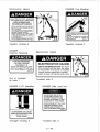
AGNfNI SNOIEZS do H1V3O NI L1NS3
NY ONIMOTIOS 3HLA390 OL 38MIV4
1666 — 626 / VOY INOHJITAL
301440 VINVILY "ON! VOIHIWY NIWOL
1OVINOO NOILYIWHOLNI H3H14dNd YO3
ONVHYI19 31YND3OVNI
НО lOvINOS MOY4 11nS3d
TIM AgNFNI SNOIEZS HO H1Y30
'SSO| JO SIJOA 000'0€ ¡euONIPPE
Áoass 10) pasnbas si soueleajp ¡BUONIPpe )00j SUO
'SIJOA 00005 0) dni BulÁueo sul ¡eoLDeja
Áue pue peo 10 sulpeoj| “eue1o au) JO Med Aue
иеэмцед 199} 01 1529) 12 10 эоичелеер E WIEJUIEN +
‘JoJonpuoo
peB.eyo Ápeoujoaje ue 0; ANWIXOId 40 yum
JOBJUOI WO4} uonoatold spiaoid Jou SSOP DURID SIU] +
"BuiAems out] peo; pue “su [eoL]09}9 ‘UIOOG 104 MoOIY
"SOU ¡eoIDAjS WO) SOOURIBS|D ajeS UNEJUIEN +
CdILVINSNI LON Si 3NVHO SIHL
CdYZYH NOILLNDOYLI913
NOLLNVO Y
ONINYVM Y
H39NVa V
-suonenBa. JUeLULISAOÓ ajgeo!¡dde pue sejni yJom s,iñoj¡duie 1noÁ “sirenueu
Ss. Jainjoejnuell suelo su) ul peurejuos suonepusuiossa, Bunesado pue Ájejes au) mojo; pue pueljsiapun ‘peos NOA 7
‘OUBJO SIU] JO LONEJOdo ejes ay] Ul pauled] usaq BABY NOA “|
-SETINN 3NYYO SIHL 31vd3d0 LON 1SAN MOA
NOILVH3dO 3H1 340439
SNOILONYLSNI INILVHIdO
O
O)
а
2— 37
( NN
CAUTION OF OUTRIGGER OPERATION —*
1. CRANE OPERATION
Extend the horizontal beams fully.
2. TRAVELLING
completely to minimum span.
A Fix the latch.
N
Check that the lock lever's "blue mark” is visible
when the horizontal beam is fully extended.
Retract the vertical jacks and horizontal beams
Check that the lock lever's “blue mark” is visible
and the horizontal beams will not come out.
Le
EXCHANGING OF FILTER
1. Lubricate oil to the packing for filter
and then screw in and tighten with
all your strength.
2. Exchange after the initial 3 month
operation, thereafter change annually.
089181060 J
CAUTION, O/R Operation,
Outrigger Housing, 2
089181070
N
Exchanging of Filter,
Filter body, 1
J
Horn,
Grease,
C=)
UNIC
——[—É
О
MODEL
CAPACITY LBS
SERIAL NO.
MFG. DATE
UNIC DEVISION
FURUKAWA CO., LTD. |
TOKYO, JAPAN @
—
О
Operator console, 2
Crane Model Name Plate,
Column, 1
NN
A
4 Maximum Load,
Side plate of Hook Block, 2
UR503
UR504
LBS. UR505 —
N
Maximum Load,
Side plate of Hook Block, 2
8 000 LBS.
Blue Mark,
Outrigger lock lever, 2
[Knob of Control Lever]
a
x
ses
>
%
Mn
>
©
©
m
Г
TI
D
x
—
O
A
Boom Topping, 2
Hook Hoisting and Lowering, 2
Boom Telescoping, 2
Swing, 2
Outrigger (Curb Side), 2
Outrigger (Street Side), 2
Accelerator, 2
Electrocution Hazard
DANGER, Two Blocking
ELECTROCUTION HAZARD
THIS CRANE IS NOT INSULATED
DEATH OR SERIOUS INJURY
WILL RESULT FROM CONTACT
OR INADEQUATE CLEARANCE
Maintain safe clearances from electrical
lines. Allow for boom, electrical line, and
load line swaying.
This crane does not provide protection
- from contact with or proximity to an
electrically charged conductor.
Maintain a clearance of at least 10 feet
between any part of the crane, loadline
or load and any electrical line carrying
up to 50,000 volts.
One foot additional clearance is required
|. for every additional 30,000 volts or less.
(ADANGER |
Operator console, 2
DANGER,
Hoisting Personnel
( ADANGER |
HOISTING PERSONNEL
ON CRAE LOADLINE
CAN RESULT IN
DEATH OR SERIOUS INJURY
Never hoist personnel on hook, load
or any device attached to loadline.
- 08A481130
A
N
End of truckbed
at hook, 1
DANGER, O/R Operation
( ADANGER |
=>
OUTRIGGERS CAN CAUSE
SERIOUS CRUSHING INJURY
STAND CLEAR
088F81050
NN J
Outrigger housing, 2
N
6 MN
Tem
A
088F81080 |
\ lowering the boom.
ADANGER |
BOOM
TWO BLOCKING THE CRANE WILL CAUSE
DEATH, SERIOUS INJURY OR PROPERTY
DAMAGE.
Do not allow the hook block to contact the
boom tip by hoisting up, extending or
OBA481110 И)
ля
Operator console, 2
Electrocution Hazard
a
n
A DANGER
ELECTROCUTION HAZARD
DEATH OR SERIOUS INJURY will result
from contact with the load, the crane
or the vehicle if the boom or loadline
should become electrically charged.
KEEP CLEAR OF TRUCK AND LOAD
beara111d
Truckbed side, 3
DANGER, Ride Load line
NEVER RIDE ON OR IN A
PLATFORM, BUCKET OR
OTHER TYPE OF LIFTING
DEVICE ATTACHED TO THE
LOADLINE OF THIS CRANE.
SUCH MISUSE OF THE LOAD-
LINE MAY SUBJECT THE
RIDERS AND OTHERS TO
DEATH OR SERIOUS INJURY.
08A481120
2
N
Truckbed side, 3
2 — 40
rene
7
TRUCK.
POSITION.
N
CAUTION]
1. INSPECT VECHICLE AND CRANE INCLUDING]
OPERATION. PRIOR TO USE DAILY.
2. DO NOT USE THIS EQUIPMENT EXCEPT ON
SOLID, LEVEL SURFACE WITH OUTRIGGERS
PROPERLY EXTENDED AND CRANE
MOUNTED ON FACTORY-RECOMMENDED
3. BEFORE OPERATING THE CRANE, REFER TO
MAXIMUM LOAD (CAPACITY) CAHRT ON
CRANE FOR OPERATING (LOAD)
LIMITATIONS.
4. OPERATE ALL CONTROLS SLOW AND
SMOOTH TO AVOID DAMAGE TO CRANE OR
INJURY TO PERSONNEL.
5. DO NOT OPERATE, WALK OR STAND
BENEATH BOOM OR A SUSPENDED LOAD.
6. FOR TRAVEL, BOOM MUST BE IN STOWED
08A481090 J)
CAUTION, Inspect Vehicle,
Operator console, 2
[О
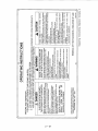
ALL SIGNS AND CHARTS ON THIS CRANE APPEAR
ALSO IN THE OWNER'S MANUAL. IF ANY OF THEM
BECOMES DIFFICULT TO READ, OR IS REMOVED OR
DAMAGED, CONSULT ITS DUPLICATE IN THE MANUAL
Replacement Warning,
Operator console, 2
Vs
SON CONTACT UNIC CORPORATION FOR A REPLACEMENT.
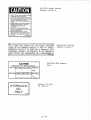
CAUTION
DISENGAGE PTO BEFORE DRIVING
MAX ENGINE SPEED FOR CRANE OPERATION
RPM
MAX ROAI
TRAVEL HEIGHT WITH 1 BOOM ANGLE
FT.
088F81080
CAUTION, RPM Roading,
Cab, 1
/
HYDRAULIC
ONLY
=~
OIL
088F81080
„
Hydraulic Oil Only,
Oil reservoir, 1
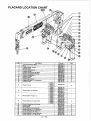
PLACARD LOCATION CHART
SECOGUOOOECCOSSSE
D
E
<
«<
tr
e
a
08A681040
Placard (Hook)
15
Placard (Boom Angle R.H.)
Placard (Boom Angle L.H.)
17
Placard (Maximum Load Chart)
EM MAINTENANCE SECTION
1. PERIODIC MAINTENANCE
The life of any piece of construction equipment is greatly influenced by operating
techniques and the quality of the care it receives.
Routine checks and service are essential for preventing breakdowns, maintaining
performance and keeping operation costs down. Also, lubrication is an important part of
any good maintenance program.
Intervals on the periodic maintenance are for operating in normal conditions. If you
operate your machine in difficult conditions, you should service it at Shorter intervals.
/N\ CAUTION
While lubricating and / or servicing, be sure to hang a caution tag on
the control lever to prevent the crane from being operated by the other
personal.
2. PERIODIC MAINTENANCE / DAILY
Daily inspection to be made before operation.
Making the inspection before operation results in using the machine safely or prevents
failures.
2-1. WALK- AROUND INSPECTION
For operator personnel safety and maximum service life of the machine, make a
thorough walk- around inspection before starting the engine.
Inspect each part of the crane according to the following service schedule.
Device Servicing item
1 Hydraulic oil reservoir Oil leakage
Loose mounting
2 | Hydraulic pump
Oil leakage
Cracks in welded parts
3 | Outriggers
Oil leakage
4 | Base Fastening tightness of crane body mounting bolts
5 | Control Valve Oil leakage
6 | Swing device Loose bolts and nuts
7 | Hydraulic piping Oil leakage from joints
Damage in fulcrum pin and boss
8 | Topping cylinder
Oi! leakage
Damage in fulcrum pin and boss
9 | Boom
Cracks in welded parts
Damage of fulcrum pin and boss
10 | Sheave pin
Rust on boss
Rotation of hook
11 | Hook
Damage of sheave
Tension of spring
12 | Hook latch
Deformation and damage
13 | Others Sling wire and other equipment necessary for crane
operation
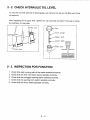
2-2. CHECK HYDRAULIC OIL LEVEL
To read the oil level with the oil level gauge, just remove the cap on the filler port of the
oil reservoir.
After supplying oil to upper limit, tighten the cap securely by hand. If the cap is loose,
the hydraulic oil may leak.
/ Filler cap (ce
ve gauge
Upper limit
Lower limit Ta
Filler port |
Drain plug ”
Хх —d
Г
«Я.
—“æ-
2- 3. INSPECTION FOR FUNCTION
Gheck that each moving part of the crane operates smoothly.
Check that the Anti- two block device operates correctly.
Check that the outrigger warning alarm operates correctly.
Check that the warning horn switch operates correctly.
Check that the winch brake operates correctly.
п в © № =
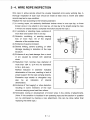
2-4. WIRE ROPE INSPECTION
Wire rope in active service should be visually inspected once every working day. A
thorough inspection of such rope should be made at least once a month and dated
records kept as to rope condition.
Replace the rope according to the following standard.
(1) In running ropes, six randomly distributed broken wires in one rope lay, or three
broken wires in one strand in one rope lay. (A rope lay is the length along the rope
in which one strand makes a complete revolution around the rope.)
(2) In pendants or standing ropes, evidence of
more than one broken wire in one lay.
(3) Abrasion, scrubbing, or peening causing
loss of more than 1/3 of the original
Rope — ae
diameter of the outside wires. diameter Su
(4) Evidence of severe corrosion. |
(5) Severe kinking, severe crushing, or other
damage resulting in distortion of the rope
structure.
(6) Evidence of any heat damage from a torch
or arc caused by contact with electrical
wires.
(7) Reduction from nominal rope diameter of
more than 1/64 in. (0.4 mm) for diameters
5/16 in. (8.0 mm);
Marked reduction in diameter indicates
deterioration of the core, resulting in lack of
proper support for the load carrying strands.
Excessive rope stretch or elongation may
also be an indication of internal
deterioration.
(8) Evidence of “bird caging” or other distortion
breed ВНГО
£ +
resulting in some members of the rope
structure carrying more load than others.
(9) Noticeable rusting or development of broken wires in the vicinity of attachments.
(Note: If this condition is localized in an operating rope and the section in question
can be eliminated by making a new attachment, this can be done rather than
replacing the entire rope.)
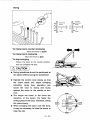
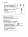
/N CAUTION
When passing a wire rope end
through the wire socket, be sure to
pass it as indicated by the arrow on
the wire socket. If it is passed in the
opposite direction, the wire rope will
be kept bent, which results in a | ire clip
shorter rope life. (Be CIEL Of ons
Do not forget to mount the wedge
and wire clip.
The arrow on the wire socket must Wire socket
face outward as shown above when
it is mounted on the hook block.
Wedge
* Adjustment when wire rope is twisted.
Under tension, wire rope turns in the untwisting direction. If two or more wire ropes
are hooked together, they tend to be twisted, particularly while they are new. They will
be free of twisting as they become used.
If the wire ropes are twisted, adjust them as described below:
(D Extend the boom fully.
(2) Set the boom to an angle of about 65°.
(3) Free the boom of load.
@ Then, check how many turns the wire ropes are twisted.
® Remove the wire socket, and turn the wire
socket in the untwisting direction as many
, Untwisting
turns as the wire ropes were twisted ; direction
multiplied by the number of wire ropes.
Remember, however, that the wire socket Wire rope's
may be turned only 4 turns at a time. twisting direction
(6) Attach the wire socket, wind the hoist to
full hoist and unwind. Repeat this a few
times, and see if the wire ropes are no
longer twisted. |
If they were still twisted, repeat the same adjustment.
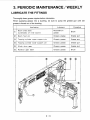
3. PERIODIC MAINTENANCE / WEEKLY
LUBRICATE THE FITTINGS
Thoroughly clean grease nipples before lubrication.
When supplying grease into a bushing, be sure to pump the grease gun until old
grease is forced out of the bushing.
Application Lubricant Procedure
© | undersides of inner boom] a Um Brush
@ | Boom foot pin Chassis grease Grease gun
@ | Topping cylinder upper support pin Chassis grease Grease gun
@ | Topping cylinder lower support pin Chassis grease Grease gun
® | Winch drum gear Chassis grease Grease gun
® | Rotation gear teeth | Chassis grease Brush
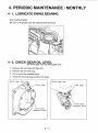
4. PERIODIC MAINTENANCE / MONTHLY
4-1. LUBRICATE SWING BEARING
Use chassis grease.
Be sure to fill grease into the bearing while turning it.
Greasing swing bearing
vA Vv 2
4-2. CHECK GEAR OIL LEVEL
for winch gear box and swing gear box.
Remove the vent plug for filler port.
Remove the oil level plug.
Fill oil up to the standard level.
Install the oil level plug and the vent plug.
DON
Winch gear A Swing gear box
DU. Vent plu Vent plu
TD plug piug
Level plug
(Standard level)
do Level plug
N & 47 (Standard level)
2
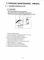
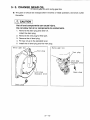
5. PERIODIC MAINTENANCE / ANNUAL
5-1. CHANGE HYDRAULIC OIL
N
/N CAUTION
Hot oil and components can cause injury.
Do not allow hot oil or components to contact skin.
Drain the oil only when engine is stopped and the oil is cool.
Filler cap
Drain plug
. Prepare a sufficient container.
The amount required for a change is about 49.5 Lit.(13 gal.)
Remove the hydraulic oil reservoir filler cap.
Remove the drain plug and drain the hydraulic oil.
Remove the four bolts to remove the cover.
Take the suction strainer out of the tank.
Clean the suction strainer in a non-flammable solvent.
Replace the strainer, if it is damaged.
Flush the tank with non-flammable solvent.
Install suction strainer and install the drain plug.
. After supplying oil, tighten the cap securely by hand.
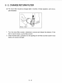
5-2. CHANGE RETURN FILTER
XxX The return filter should be changed after 3 months of initial operation, and once a
year thereafter,
Return filter
1. Turn the return filter counter- clockwise to remove and discard the element. If the
filter is hard to loosen, use the filter wrench.
2. Clean the filter base. Lubricate oil to the packing for new filter and then screw in and
tighten with all your strength.
5-3. CHANGE GEAR OIL
for winch gear box and swing gear box
% The gear oil should be changed after 6 months of initial operation, and once a vear
thereafter.
/N CAUTION
Hot oil and components can cause injury.
Do not allow hot oil or components to contact skin.
1. Remove the drain plug and drain oil.
Install the drain plug.
Remove the vent plug for filler port.
Remove the oil level plug.
Fill new oil up to the standard level.
Install the oil level plug and the vent plug.
о к © №
Swing gear box
Winch gear b
Vent plug
yn Level plug
\ & 7 (Standard level)
O
Drain plug
3 — 10
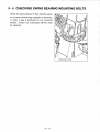
5-4. CHECKING SWING BEARING MOUNTING BOLTS
When the swing device of this machine gives
out unusual noise during operation or traveling,
or when a gap is produced on the mounting
surface, contact our authorized service shop
for repairing.
3—11
Mounting bolts
6. PERIODIC MAINTENANCE /
REPLACEMENT OF EXPENDABLE PARTS
Replace the following parts periodically in order that the strength and quality of the
original machine may be maintained.
When you replace the above parts, contact UNIC CORPORATION or the authorized
dealer.
Replacement parts
Replacement intervals
Hoist winch brake shoe
every 3 years
Boom wear pads
every 3 years
Packings, O-rings and Dust-seals
for telescoping cylinder,
topping cylinder, and
outrigger cylinder.
every 3 years
3—12
H OTHERS
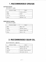
1. RECOMMENDED GREASE
(a) Chassis grease
Use NLGI No. 1 grade.
Petroleum Maker Brand
ESSO Chassis grease L
MOBIL HP221
CALTEX Multifak EPI
SHELL RETINAX — CD
(b)Molybdenum grease
Use NLGI No. 2 grade.
Petroleum Maker Brand
ESSO Beacon Q2
MOBIL Mobilplex Special
CALTEX Molytex Grease EP2
SHELL Retinax AM
2. RECOMMENDED GEAR OIL
Use API Service GL- 4 gear oils.
Petroleum Maker Brand
ESSO Standard gear oil 90
MOBIL | Mobilube SAE 90
CALTEX Universal Thuban SAE 90
SHELL | Shell Spirax EP 90
3. RECOMMENDED HYDRAULIC OIL
Use industrial- type hydraulic oil;
ISO VG 46 for most temperatures.
ISO VG 32 extremely low temperatures.
Petroleum Brand
Maker ISO VG 32 ISO VG 46
ESSO UNVICE J32 Teresso 46
MOBIL Mobil DTE 13 Mobil DTE 25
CALTEX Rando Oil HD AZ32 Rando Oil 46
SHELL Shell Tellus Oil 32 Shell Tellus Oil 46
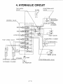
4. HYDRAULIC CIRCUIT
COUNTERBALANCE
TWO-BLOCK
VALVE
CONTROL VALVE
| or
PILOT CHECK VALVE SWING FAIT
N
BOOM HT
HOIST Cat hy | 1
A
EXTENTION HT
VALVE
Е
BOOM
TOPPING
N CYLINDER
BN
Lis | |,
| HOIST MOTOR
U
TELESCOPING CYLINDER
EA}
\ АИ A Y
> al: ™ de
= LL 0 HINES |
| 1 Г 1 | 2 mi I
LT T1 G.P =
PT1/4 ı 1 2850psi
STRAINER PUMP
STREETSIDE CURBSIDE
OUTRIGGER CYLINDER [2 |
OIL RESERVOIR
BN
r--+ '
m.
Lis |
SWING MOTOR:
COUNTERBALANCE VALVE
FURUKAWA UNIC Corporation