1
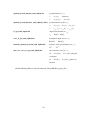
ΩMaxEnt user guide
Dominic Bergeron
August 25, 2015
Contents
1
2
Introduction
4
1.1
Overview . . . . . . . . . . . . . . . . . . . . . . . . . . . . . . . . .
4
1.2
Type of data accepted . . . . . . . . . . . . . . . . . . . . . . . . . . .
5
1.3
What the program does . . . . . . . . . . . . . . . . . . . . . . . . . .
6
Step-by-step guide to ΩMaxEnt
8
2.1
The parameter files . . . . . . . . . . . . . . . . . . . . . . . . . . . .
8
2.2
Set the input data . . . . . . . . . . . . . . . . . . . . . . . . . . . . .
9
2.2.1
G(iωn ) as input . . . . . . . . . . . . . . . . . . . . . . . . . .
9
2.2.2
Temperature . . . . . . . . . . . . . . . . . . . . . . . . . . .
10
2.2.3
G(τ ) as input . . . . . . . . . . . . . . . . . . . . . . . . . . .
10
2.2.4
Bosonic data . . . . . . . . . . . . . . . . . . . . . . . . . . .
11
2.2.5
Self-energy . . . . . . . . . . . . . . . . . . . . . . . . . . . .
11
2.2.6
Most basic execution . . . . . . . . . . . . . . . . . . . . . . .
11
Set errors . . . . . . . . . . . . . . . . . . . . . . . . . . . . . . . . .
12
2.3.1
Uncorrelated errors . . . . . . . . . . . . . . . . . . . . . . . .
12
2.3.2
Correlated errors . . . . . . . . . . . . . . . . . . . . . . . . .
12
2.3.3
Basic execution . . . . . . . . . . . . . . . . . . . . . . . . . .
13
Control how moments are used . . . . . . . . . . . . . . . . . . . . . .
13
Use ΩMaxEnt to extract moments . . . . . . . . . . . . . . . .
14
2.3
2.4
2.4.1
1
2.4.2
Special case of the norm of the spectrum . . . . . . . . . . . .
15
2.4.3
Providing moments . . . . . . . . . . . . . . . . . . . . . . . .
15
2.4.4
G(τ ) as input data . . . . . . . . . . . . . . . . . . . . . . . .
16
2.4.5
Basic execution . . . . . . . . . . . . . . . . . . . . . . . . . .
17
2.5
Provide a user-defined grid . . . . . . . . . . . . . . . . . . . . . . . .
17
2.6
Provide a user-defined default model . . . . . . . . . . . . . . . . . . .
19
2.7
Execution . . . . . . . . . . . . . . . . . . . . . . . . . . . . . . . . .
20
2.8
Output figures . . . . . . . . . . . . . . . . . . . . . . . . . . . . . . .
22
2.9
How the optimal α is chosen . . . . . . . . . . . . . . . . . . . . . . .
23
˜=G
˜ in − G
˜ out at the optimal α
2.10 Properties of ∆G
3
. . . . . . . . . . . .
25
2.11 Spectrum at sample frequencies vs α . . . . . . . . . . . . . . . . . . .
26
2.12 Output files . . . . . . . . . . . . . . . . . . . . . . . . . . . . . . . .
27
2.13 When is the calculation over . . . . . . . . . . . . . . . . . . . . . . .
30
2.14 How to improve the results . . . . . . . . . . . . . . . . . . . . . . . .
31
List of input parameters
32
3.1
OPTIONAL PREPROCESSING TIME PARAMETERS . . . . . . . .
32
3.1.1
DATA PARAMETERS . . . . . . . . . . . . . . . . . . . . . .
32
3.1.2
INPUT FILES PARAMETERS . . . . . . . . . . . . . . . . .
35
3.1.3
FREQUENCY GRID PARAMETERS . . . . . . . . . . . . . .
37
3.1.4
COMPUTATION OPTIONS . . . . . . . . . . . . . . . . . . .
38
3.1.5
PREPROCESSING EXECUTION OPTIONS . . . . . . . . . .
39
2
3.2
OPTIONAL MINIMIZATION TIME PARAMETERS . . . . . . . . .
40
3.2.1
OUTPUT FILES PARAMETERS . . . . . . . . . . . . . . . .
40
3.2.2
COMPUTATION PARAMETERS . . . . . . . . . . . . . . . .
41
3.2.3
MINIMIZATION EXECUTION OPTIONS . . . . . . . . . . .
42
3.2.4
DISPLAY OPTIONS . . . . . . . . . . . . . . . . . . . . . . .
42
A How the program estimates the width of a low energy peak
43
B Other parameters
44
3
1
Introduction
1.1
Overview
This is the user guide for the program ΩMaxEnt, a tool to perform the analytic continuation of Matsubara data using a maximum entropy aproach. It can treat fermionic or
bosonic data, given as a function of Matsubara frequency or imaginary time, with either
a diagonal or general covariance matrix. For the fermionic case, the output is a positive
spectral function A(ω) and, for the bosonic case, it is the function σ(ω) = A(ω)/ω, also
positive.
A specific feature of ΩMaxEnt is the method it uses to find the optimal value of the
entropy weight parameter α. It does not use either the classic approach or Bryan’s, but
instead locates the range of α where only information is fitted and the range where noise
is also fitted. The optimal value is then chosen in the crossover between the two regimes.
The program also offers useful graphical diagnostic tools for assessing the quality of the
results.
In addition, the program uses a cubic spline to model the spectral function and uses
the Matsubara frequency spectral representation of the Green function instead of the
imaginary time version. Those two choices allow to compute the Green function corresponding to a given spectral function with high accuracy by a piecewise analytical
integral. The use of a non-uniform grid for the spectral function and contraints on moments instead of a high Matsubara frequency cutoff also allows to improve calculation
efficiency without losing accuracy. Basically, the code is optimized to ensure that the
errors in the results comes from the errors in the data and not from numerical approximations.
You can obtain results by providing only a data file name to the program. It is
however highly recommended to provide also errors (standard deviation or covariance
4
matrix) if reliable estimates are available. You can also further improve the results by
providing more information, like some known moments of the spectral function, a default model, or by providing a frequency grid adapted to the expected structures of the
spectral function.
The next two subsection of this introduction present the basic theoretical aspects
necessary to understand what you are doing when using this program. Then section 2
describes how to use ΩMaxEnt step-by-step. You can execute the program already at the
end of subsection 2.2 to get some preliminary results. The following subsections give you
the possibility to use more information you might possess to improve the result. Some
explanations on how the program works and advices on how to interpret and improve the
results are given at the end of the section. Lists of the output figures and the output files
are given in subsections 2.8 and 2.12, respectively. Finally, section 3 presents a list of all
the input parameters with a short description of each one.
For simplicity, throughout this guide, the Matsubara data is referred to as the “Green
function” G, but the data can be a correlation function, a self-energy or any Matsubara
function satisfying the conditions given in the next section. The result obtained with the
program is also referred to as the spectral function A, although for bosonic data, it is
actually σ(ω) = A(ω)/ω.
1.2
Type of data accepted
The program can treat data that can be expressed as
Z
∞
dω A(ω)
2π iωn − ω
(1.1)
dω e−ωτ A(ω)
,
2π 1 ± e−βω
(1.2)
G(iωn ) =
−∞
or
Z
∞
G(τ ) =
−∞
5
where A(ω) > 0 for fermions or σ(ω) = A(ω)/ω > 0 for bosons, and the + and − signs
in the denominator of (1.2) are for fermions and bosons, respectively. The overall sign
on the right-hand side of those expressions can also be different, the program will detect
which convention you are using.
Those expressions are spectral representations which apply very generally to Green
and correlation functions. They imply that G(−iωn ) = G∗ (iωn ) and that Re[G(iωn )]
and Im[G(iωn )] behave asymptotically as 1/ωn2 and 1/(iωn ), respectively, as ωn → ∞.
The positivity of A(ω) or σ(ω) is an additional constraint necessary for the maximum entropy method to be applicable. Assuming the same sign convention as in
(1.1), it implies that sign(Im[G(iωn )]) = −sign(ωn ) in the case of fermions and that
Re[G(iωn )] < 0 for bosons.
ΩMaxEnt can treat directly any data satisfying those conditions. This includes a
wide variety of Green or correlation functions, but also the dynamical part of a selfenergy Σ(iωn ). In the latter case, it is better to know in advance the value of the static
part if it is not already subtracted from the data.
ΩMaxEnt takes column-wise data files with only spaces between the columns.
1.3
What the program does
Finding the spectrum A(ω) corresponding to a given G(iωn ) by numerically inverting
expression (1.1) or (1.2) does not work. The errors on A(ω) resulting from the ones on
G(iωn ) would be greatly amplified and the result would not make sense. This is what
is called an ill-conditioned problem. Instead, the program uses the maximum entropy
approach, which consists in minimizing
Q = χ2 − αS ,
6
(1.3)
where
χ2 =
X
−1
(Gm − Km A)T Cmn
(Gn − Kn A) ,
(1.4)
mn
where A is the vector obtained after discretizing ω, Kn is a row vector such that Kn A
is an approximation to (1.1), and C is the covariance matrix. S is a differential entropy,
defined as
Z
S=−
dω
A(ω)
A(ω) ln
,
2π
D(ω)
(1.5)
where D(ω) is called the default model, and α is a parameter to be determined. The
solution that minimize (1.3) if χ2 is negligible, namely that maximizes the entropy S, is
e−1 D(ω), hence the name default model. D(ω) is defined in a way to include what is
known a priori about the spectrum.
The maximum entropy approach is based on Bayesian inference, which consists basically in using the information you know in advanced about the spectrum to deduce it
from incomplete or noisy data, which alone is not sufficient to obtain acceptable results.
In the present case, the entropy term αS is used to include that information.
To find the optimal value for α, the program first computes the solution to min(χ2 −
αS) for a large range of α. The location of the optimal α can then be found by a simple
analysis of the shape of the function log (χ2 ) as a function of log(α). The procedure is
described in subsection 2.9.
Note that if we diagonalize the covariance matrix C, defining
˜ = U† CU ,
C
(1.6)
˜ T (G
˜ ,
˜ − KA)
˜ − KA)
χ2 = (G
(1.7)
χ2 can be written
7
where
p
˜ −1 U† G ,
C
p
˜ = C
˜ −1 U† K .
K
˜=
G
(1.8)
This form is more useful for practical calculations and analysis of the results.
Step-by-step guide to ΩMaxEnt
2
2.1
The parameter files
The program uses two parameter files: OmegaMaxEnt_input_params.dat and OmegaMaxEnt_other_params.dat. The main parameter file used to control the calculation is
OmegaMaxEnt_input_params.dat. The other parameter file should be modified by experienced users only, or according to instructions in this guide. The only mandatory parameter in OmegaMaxEnt_input_params.dat is the data file name on the first line. Although
not recommended, you can obtain results even if all the other fields are left blank. When
a parameter can have the values “yes” or “no”, leaving the field blank or putting anything
else than “yes” corresponds to the default value “no”. The parameters other than the data
file name are divided in two sections. The parameters defined in the section OPTIONAL
PREPROCESSING TIME PARAMETERS are used to set all the variables in the optimization problem. The parameters defined in the section OPTIONAL MINIMIZATION
TIME PARAMETERS control what happens during the search for the optimal solution
to the problem. They can be modified without triggering the preprocessing. Some of
them can be modified during the optimization itself, as explained in subsection 2.7.
Before doing your first analytic continuation with ΩMaxEnt, create the two parameter
files by executing the file OmegaMaxEnt. The file OmegaMaxEnt_input_params.dat will
be created with all the fields blank and OmegaMaxEnt_other_params.dat will be created
8
with the default values of its parameters. When you define a parameter in OmegaMaxEnt_input_params.dat, that parameter is printed on the terminal as the program reads
the file. As for the parameters in OmegaMaxEnt_other_params.dat, they are printed out
only if you modify the default value. It is important not to modify any parameter’s name,
namely, any caracter up to ‘:’ on a line. If you define a parameter or modify one’s default
value in one of the two parameter files and this parameter is not printed on screen when
the program reads the file, it means you inadvertently modified its name in the parameter
file and the program cannot find it anymore. If that happens, destroy the file and execute
ΩMaxEnt to create the default version of the missing parameter file.
Unless mentioned otherwise, all the input parameters referred below are defined in
the file OmegaMaxEnt_input_params.dat.
2.2
Set the input data
Put the input file name on the line “data file”, the first line in OmegaMaxEnt_input_params.dat.
If your data file is not in the same directory as the code, you can set “input directory”
in subsection INPUT FILES PARAMETERS which tells the program where to look first
for your files. If a file is not found in that directory, the program then looks for it in the
current directory.
2.2.1 G(iωn ) as input
The data is always assumed to be given by columns in the data file, with the first column
being the Matsubara frequency ωn when the input data is G(iωn ). By default the next
two columns are assumed to be the real and imaginary parts of G, respectively:
ωn
Re[G]
9
Im[G]
(2.1)
If G is not on the 2nd and 3rd columns, write the correct column numbers on the lines
“Re(G) column in data file” and “Im(G) column in data file” in the subsection INPUT
FILES PARAMETERS.
2.2.2
Temperature
If the Matsubara frequencies do not have high precision in your data file or if the first column gives only the frequency indices, set the parameter “temperature” in the subsection
DATA PARAMETERS.
2.2.3 G(τ ) as input
For a Green function given in imaginary time G(τ ), first set the parameter “imaginary
time data” to “yes” in the subsection DATA PARAMETERS. By default, the columns in
the data file are assumed to be
τ
G
(2.2)
If G is not on the 2nd column, put the correct column number on the line “column of
G(tau) in data file” in subsection INPUT FILES PARAMETERS. Note that the imaginary
time grid must be uniform and go from 0 to 1/T , where T is the temperature. If the
temperature is specified in the subsection DATA PARAMETERS, the imaginary time
grid will be redefined using the provided temperature. Otherwise, T is assumed to be
1/τmax , where τmax is the last value of τ in the input file.
To get good results if your data is G(τ ), the step ∆τ must be small enough. See
subsection 2.4.4 for more details.
10
2.2.4
Bosonic data
If G is bosonic, set the parameter “bosonic data” to “yes” in subsection DATA PARAMETERS.
If G(iωn ) is also real (or G(τ ) is symmetric with respect to τ = β/2), set “Im(G)
column in data file” to a value ≤ 0. The code will then assume an odd spectral function
(σ(ω) even). This is the case of a correlation function of observables having the same
signature under time reversal.
2.2.5
Self-energy
If your data is a self-energy and the static part (the Hartree-Fock value) has been subtracted, it can be treated the same way as a Green function. Otherwise, if you know the
value of the static part, set parameter “static part of data” in subsection DATA PARAMETERS. If you do not know it, an estimate is the value of Re[Σ(iωn )] at high frequency.
If you have enough frequencies, the latter function should become constant. If you have
put the correct value, when the moments are evaluated (see section 2.4.1), there should
be a plateau in the value of M1 that is plotted as a function of the fit starting frequency.
If it is not the case, then the provided value is incorrect. However, if there are not many
frequencies in the asymptotic part of the data, it is possible that only the beginning of a
saturation can be seen. Note that “display preprocessing figures” must be set to “yes”
in section PREPROCESSING EXECUTION OPTIONS to see the figures when the moments are evaluated.
2.2.6
Most basic execution
If you do not have more information than the Green function itself, you can execute
ΩMaxEnt now. See section 2.7 for more details on the execution. If you have more
information or want to learn about other functionalities, follow the next steps or see
11
section 3.
2.3
Set errors
As mentioned in section 1.3, the data’s covariance matrix C is used during the calculation. For a given set of data G(iωn ), the accuracy of C actually controls how well the
information contained in G can be transferred into the resulting spectrum A(ω). For the
remaining of the guide, unless mentioned otherwise, the term “error” is used in a broad
sense, sometimes meaning the standard deviation of data points or, more generally, referring to the covariance matrix.
The program can treat the case of a general, non-diagonal, covariance matrix, but
you can simply provide the standard deviation in the case of diagonal covariance.
2.3.1
Uncorrelated errors
If the errors on the elements of G are uncorrelated, define the parameter “error file” in the
subsection INPUT FILES PARAMETERS and the correct column numbers on the lines
“Re(G) column in error file” and “Im(G) column in error file” if the input is G(iωn ), or
on the line “column of G(τ ) error in error file” if the input is G(τ ), unless the column
number(s) correspond to the default value(s).
2.3.2
Correlated errors
If the errors are correlated between elements of G and you have the covariance matrix
N
1 X l
Cij =
Gi − hGi i Glj − hGj i
N − 1 l=1
12
(2.3)
where N is the number of sample values for each element Gi , Gli is the lth sample of Gi ,
and
N
1 X l
hGi i =
G ,
N l=1 i
(2.4)
then, in subsection INPUT FILES PARAMETERS, provide that matrix using the parameters “re-re covariance file”, “im-im covariance file” and “re-im covariance file”, if the
input is G(iωn ), or “imaginary time covariance file”, if the input is G(τ ). Those files
must contain an equal number of lines and columns.
2.3.3
Basic execution
If you do not have more information, you can execute ΩMaxEnt now. See section 2.7 for
more details on the execution. If you have more information or want to learn about other
functionalities, follow the next steps or see section 3.
2.4
Control how moments are used
The part of the Green function at frequencies ωn > W , where A(|ω| > W ) = 0, can be
expressed as a high frequency expansion, of which the coefficients are the moments of
the spectral function A(ω). However, because of finite precision and noise, the information on high order moments is not present in the data. Therefore, the high frequencies
of G(iωn ) contain the information about a few moments only. It is thus numerically
equivalent, but computationally more efficient to replace the large number of constraints
corresponding to those high frequencies in the calculation by the few contraints corresponding to those moments.
The moments are also used during the definition of the real frequency grid and the
default model, since they tell us about global properties of the spectrum, among which
the center and the width of the spectrum.
13
2.4.1
Use ΩMaxEnt to extract moments
If the Matsubara frequency cutoff ωnmax of your data is in the asymptotic part of G(iωn ),
namely that the condition ωnmax > W is satisfied, the program can extract moments from
your data by fitting a high frequency expansion to the asymptotic part, and determine the
onset of the asymptotic regime at the same time. Unless you provide enough moments
or real frequency grid parameters, ΩMaxEnt will try to extract them and use them in the
calculation instead of the high frequencies they are extracted from. When it performs
that procedure, if you set the parameter “display preprocessing figures” to “yes” in subsection PREPROCESSING EXECUTION OPTIONS, you can check for convergence in
the computation of the moments from the figures of the norm M0 and the first moment
M1 plotted as a function of the starting frequency of the fit. If there is a plateau in those
curves above a certain frequency, then the values are converged.
In any case, you can force the program to extract the moments by setting “evaluate
moments” to “yes” in subsection COMPUTATION OPTIONS. You can also control how
many moments are used during the computation of the spectrum with the parameter
“maximum moment” in the same subsection. By default, ΩMaxEnt imposes the first 4
moments (including the norm M0 ) to the spectrum for fermions, and the first 3 moments
for bosons. For example, if you want the program to impose only the norm and the first
moment, set “maximum moment” to 1.
You can also control the maximum frequency to be used in the calculation with the
parameter “Matsubara frequency cutoff” in subsection FREQUENCY GRID PARAMETERS. For example, if you do not have enough frequencies in the asymptotic frequency
range, it is probably better to use all the frequencies instead of the moments by setting
“maximum moment” to 0 (if the norm is known exactly) and “Matsubara frequency cutoff” to a value larger than the last frequency in your data.
14
2.4.2
Special case of the norm of the spectrum
If your spectrum is normalized to 1, namely, if the leading high frequency term of the
Green function is 1/(iωn ), you do not have to provide the norm. Also, if you have real
bosonic Matsubara data and have set “Im(G) column in data file” to 0 or less, the norm
is automatically assumed to be 0.
Otherwise if the norm is not 1, use “norm of spectral function” in subsection DATA
PARAMETERS to provide it. If you do not know it, you can let the program extract it
first and use the value printed in the terminal. To do so, set “evaluate moments” to “yes”
in subsection COMPUTATION OPTIONS and “preprocess only” to “yes” in PREPROCESSING EXECUTION OPTIONS to prevent the actual calculation from starting after
the preprocessing. It is also better to set “display preprocessing figures” to “yes” to verify convergence on the figure of M0 . Once “norm of spectral function” is set, you can
disable “preprocess only” and continue the execution.
If you do not know the norm and there is not enough frequencies in your data to
allow the program to extract it, namely there is no plateau in the figure of M0 , just tell
the program not to use moments at all by setting “maximum moment” to −1 or less.
2.4.3
Providing moments
If you know some moments of the spectral function with good precision, you can provide
them with their respective errors in subsection DATA PARAMETERS.
If you provide enough moments (first and second for fermions, first for bosons),
the program will not try to extract them from your data. In that case however, it is
recommended to set “evaluate moments” and “display preprocessing figures” to “yes”
in subsection COMPUTATION OPTIONS when running ΩMaxEnt for the first time
with a given set of data. This way, provided that your data has some frequencies in
the asymptotic part of G (if so, there will be a plateau in the figures of M0 and M1 ),
15
you can verify if the moments you provided have values close to the ones extracted,
which will be printed in the terminal. In addition, the program will also print where the
asymptotic regime sets in. This verification step is important to make sure you do not
impose wrong moments to the spectrum, which is worse than not imposing any. When
making that verification, set “preprocess only” to “yes” to prevent the actual calculation
from starting.
Once you provided moments, if your Matsubara frequency cutoff is far in the asymptotic part of G (there are long plateaus in the figures of M0 and M1 when “evaluate
moments”), set “Matsubara frequency cutoff” in subsection FREQUENCY GRID PARAMETERS to the onset value given by the program. Note that this is done automatically if “evaluate moments” is enabled. If the asymptotic regime is not reached at the
cutoff, you can make sure that all the frequencies are used, whatever the value of “evaluate moments” is, by setting “Matsubara frequency cutoff” to a value larger than the
cutoff.
2.4.4 G(τ ) as input data
If you have imaginary time data, the first two finite moments M1 and M2 are necessary to
Fourier transform G(τ ) before computing the spectrum from the resulting G(iωn ) (with
which ΩMaxEnt works internally). Thus in that case either you provide those moments,
or the program extracts them from G(τ ). In the latter case, it does so using a polynomial
fit to G(τ ) around the boundaries τ = 0 and β. The condition for that fit to give the
correct moments is that ∆τ < 1/W (see introduction of section 2.4 for the definition of
W ), where ∆τ is the imaginary time step. This condition is equivalent to ωnmax > W .
Ideally, ∆τ should be at least a few times smaller than 1/W . Thus, if you provide G(τ )
as the input data and do not know M1 and M2 , make sure the imaginary time step is
small enough so that this condition is satisfied. If you do know M1 and M2 with good
accuracy, note however that, even though the Fourier transform of G(τ ) will be accurate,
16
the Fourier transform of the error will not be if ∆τ is not small enough, which may
degrade the quality of the result. It is thus preferable that the condition ∆τ < 1/W be
well satisfied in any case.
2.4.5
Basic execution
You can execute ΩMaxEnt here. See section 2.7 for more details on the execution. Otherwise, follow the next steps or see section 3 to learn about other functionalities.
2.5
Provide a user-defined grid
The real frequency grid used by ΩMaxEnt is separated in two different types of grid:
a central dense part, let us call it the main spectral range, where most of the spectral
weight should be found, and two non-uniform high frequency parts, where the step size
increases approximately quadratically with the module of the frequency. Let us address
how to control the grid in the main spectral range first.
By default, in that range, the program uses a uniform grid of width SW = 2∆ωstd ,
p
where ∆ωstd = M2 − M12 (fermionic case) is the standard deviation of the spectrum,
and centered on SC = M1 (the Mi s are the moments of the spectrum). The number of
frequencies in that region is defined in two possible ways: if there is a sharp and well
isolated peak at low frequency, the program can estimate its width directly from the Matsubara data (see appendix A) and use a step appropriate to resolve that peak, otherwise,
the step is defined as SW/Rmin_SW_dw, where Rmin_SW_dw is defined in file OmegaMaxEnt_other_params.dat. This grid is of course not optimal in many cases, especially
for spectra possessing very broad and very sharp features at the same time. Fortunately,
ΩMaxEnt offers a few ways to define a better adapted grid with the parameters of subsection FREQUENCY GRID PARAMETERS:
17
1. The simplest way is by setting one or more of the parameters “spectral function
width”, “spectral function center” and “real frequency step”. The first two of those
parameters are used for SW and SC, instead of the default ones defined from
the moments, to define the main spectral range as [SC − SW/2, SC + SW/2]
with a uniform step given by “real frequency step”. The default values, given in
the previous paragraph, are used for those of these parameters that are left blank.
You can also make sure that a specific frequency is included in the grid with the
parameter “real frequency grid origin”. This is useful, for example if the position
of a peak is known precisely, to make sure that there is a grid point at the maximum.
If “real frequency grid origin” is not defined, but “spectral function center” is, the
two values will coincide.
2. One can also define a non-uniform grid in the central range by setting the parameter “use parameterized real frequency grid” to “yes” and by defining intervals
and their respective steps on the line “grid parameters”. The format of that line
is “ω0
∆ω0
ω1
∆ω1
. . . ωN −1
∆ωN −1
ωN ”, where the ωi ’s are the fre-
quencies delimiting the intervals and the ∆ωi ’s are the steps in those intervals. The
program then generates a grid with a step varying smoothly (with a hyperbolic tangent shape) between intervals. This grid is then used in the main spectral range.
Note that it is important not to change the step too quickly between contiguous
intervals. There should not be more than a factor of three from one interval to it
neighbors, otherwise spurious structures may appear in the spectrum at the boundaries between intervals. Each interval should also contain at least 10 points, to ensure that ∆ω vary smoothly with ω, a necessary condition to obtain high quality results. Another parameter, RW_grid, defined in OmegaMaxEnt_other_params.dat,
controls how that non-uniform grid is generated. It defines the ratio of an interval
width to the transition region between its step and the neighboring intervals’ steps.
3. Finally, you can provide your own grid with the parameter “real frequency grid
18
file”. The grid must be on the first column of the file. Note however that, unless
it is a grid that was previously generated by ΩMaxEnt, it will be used only in
the main spectral range, which is defined either by the default values of SW and
SC or by “spectral function width” and “spectral function center”. On the other
hand, if the file you provide is a spectrum obtained by the program in a previous
calculation, the whole grid, including the high frequency parts, will be identical to
the provided one.
As for the grid in the regions outside the central region, it is always defined in the
same way by the program. Instead of having a uniform step ∆ω, the grid in those regions
is such that ∆u = ui+1 − ui is constant, where ui = 1/(ωi − ω0l ) on the left side and
ui = 1/(ωi − ω0r ) on the right side. Here, ω0l and ω0r are frequencies determined by
the extrema of the grid, which can be controlled by the parameter f_w_range defined in
file OmegaMaxEnt_other_params.dat. More precisely, f_w_range is the ratio of the total
size of the grid ωmax − ωmin to the width of the main spectral range SW .
2.6
Provide a user-defined default model
By default, the default model is a gaussian of width equal to the standard deviation
p
M2 − M12 (fermionic case), if M1 and M2 are defined (provided by you
∆ωstd =
or extracted from the data), or equal to parameter “spectral function width” (subsection FREQUENCY GRID PARAMETERS), and centered on M1 (fermionic case), or
“spectral function center” (subsection FREQUENCY GRID PARAMETERS) if M1 is
not defined.
If you want to use a different default model, there are two options:
1. You can use the parameters “default model center” (DC), “default model half
width” (DW ) and “default model shape parameter” (DS) in subsection COMPUTATION OPTIONS to use a default model that has a generalized normal distribu19
tion form. As special cases, if DS = 1, this corresponds to a Laplace distribution,
if DS = 2, it is a gaussian, and as DS → ∞, the distribution becomes uniform in
the range [DC − DW, DC + DW ]. It is recommended to set “default model shape
parameter” to a value larger than 1, since for DS ≤ 1, there is a discontinuity in
the derivative at DC, which is not physical in general, except in the presence of a
Van Hove singularity.
2. You can also use your own default model by setting the parameter “default model
file” (subsection COMPUTATION OPTIONS). It is assumed that the first column
is the grid and the second column is the function value. The grid on which your
function is defined can be arbitrary, the program uses cubic splines to interpolate
your function on the active grid, namely the one set previously during preprocessing. If your grid does not extend over the whole active grid, the program will
extend your function with gaussians matching it as smoothly as possible at the
extrema of your grid.
The default model is always normalized to the same value as the spectrum, namely
M0 in the fermionic case, or G(iωn = 0) in the bosonic case.
2.7
Execution
ΩMaxEnt runs in an interactive loop. There are a few ways, given below, to pause the
execution to see the result at a given stage and with a given set of input parameters. At
the pause, the program always asks if you want to continue execution. To do so, simply
press ENTER, or enter anything else than ’y’ to stop. During a pause, you can make
changes to the parameter files. Depending on the type of changes you made, execution
can resume either from the point it halted, or at an earlier stage. If you modify a parameter in section OPTIONAL PREPROCESSING TIME PARAMETERS during a pause,
the preprocessing starts over. On the other hand, the parameters in section OPTIONAL
20
MINIMIZATION TIME PARAMETERS, with the exception of “initialize preprocessing”, can be modified during a pause without triggering the preprocessing when execution continues. Some parameters in that subsection will however cause the minimization
stage to restart at the initial (highest) α if they are modified, namely “output directory”,
“spectral function sample frequencies”, “initial value of alpha” and “initialize maxent”.
To pause execution, you can use one of the following parameters:
• “preprocess only” (subsection PREPROCESSING EXECUTION OPTIONS),
• “minimum value of alpha” (αmin ) (subsection COMPUTATION PARAMETERS),
• “number of values of alpha computed in one execution” (Nαmax ) (subsection MINIMIZATION EXECUTION OPTIONS).
The parameter “preprocess only” can be used to do some verifications with input
parameters, and try different values, before starting the actual calculation. For example,
you can verify the values of moments with the ones extracted from the data, or check that
your grid has a reasonable number of frequencies. If “display preprocessing figures” is
enabled (subsection PREPROCESSING EXECUTION OPTIONS), the preprocessing
stops when a group of figures is displayed, and you have to close them to resume it. This
pause is not the right time to modify the parameter files however, since they will not be
read when execution resumes once the figures are closed. Once you are satisfied with the
input parameters, you can disable “preprocess only” to start computing the spectrum.
The parameters “minimum value of alpha” and “number of values of alpha computed
in one execution” can be used to look at the results at intermediate stages during minimization time, where the spectrum is computed as a function of α. By default, at each
pause during that part of the calculation, the program displays figures showing the results
at the optimal α, if it has been found, and at the last (lowest) value of α computed. A list
of the output figures is given in section 2.8. Once you have closed all the figures, the program asks you if you want to continue execution. You can also choose which groups of
21
figures are displayed with parameters “show optimal alpha figures”, “show lowest alpha
figures” and “show alpha dependant curves” in subsection DISPLAY OPTIONS.
If you have set “minimum value of alpha” and αmin is reached before the condition
for the calculation to be over is satisfied (see section 2.13), the program will tell you
that αmin is not small enough and will reduce it by the factor f_alpha_min, defined in
file OmegaMaxEnt_other_params.dat, before asking if you want to continue execution.
If you have set “number of values of alpha computed in one execution”, the spectrum
will be computed for Nαmax values of α each time the calculation is resumed, unless that
parameter is emptied during a pause.
2.8
Output figures
The following functions are plotted when the execution stops during the minimization
stage:
• log (χ2 ) versus log (α) ,
• Curvature of log (χ2 ) vs log (α) ,
• Spectral function at the lowest α (αlow ): A vs ω ,
• Spectral function at the optimal α (αopt ): Aopt vs ω (if αlow < αopt ) ,
• Spectral function at sample frequencies: A(ωsamp ) versus α ,
˜ =G
˜ in − G
˜ out versus frequency index n (diagonal covari• Normalized error ∆G
ance) or covariance eigenvector index ic (general covariance), at the lowest α ,
˜ opt versus frequency index n (diagonal covariance) or covari• Normalized error ∆G
ance eigenvector index ic (general covariance), at the optimal α (if αlow < αopt ) ,
˜ vs ∆n (diagonal covariance) or ∆ic (general covariance)
• Autocorrelation of ∆G
at the lowest α ,
22
˜ opt vs ∆n (diagonal covariance) or ∆ic (general covariance)
• Autocorrelation of ∆G
at the optimal α (if αlow < αopt ).
In the figure showing the spectrum at αopt , a spectrum at a value of α slightly below
αopt and one at a value slightly above are also plotted. Those two other values of α,
say αopt− and αopt+ , delimit the range of the crossover region between the informationand the noise-fitting regimes. Along with the optimal spectrum, the spectra at αopt− and
αopt+ tell how stable the spectrum is around αopt , and thus how accurate the results are
(see also section 2.11).
2.9
How the optimal α is chosen
If you look at log (χ2 ) as a function of log (α) for a large enough range of α, you will
notice that there are three regimes in that function. At high α, the entropy term αS
dominates in the quantity Q = χ2 − αS that is minimized with respect to the spectrum
A (see section 1.3). Thus, χ2 decreases very slowly with α and the spectrum stays close
to default model. We may call this the default model regime. At intermediate values
of α, χ2 decreases rapidly as α decreases. This is the regime where the information
in input data Gin is gradually integrated in the spectrum A(ω) (or Gout = KA) as α
decreases. It is thus an information-fitting regime. Finally, when most of the information
in Gin is already present in A(ω), the noise in Gin starts to be integrated into A(ω), as
∆G = Gin − Gout becomes smaller than the error on Gout . At that point, the rate of
change of χ2 with α decreases rapidly, and becomes very small, in what we may call
the noise-fitting regime. The optimal alpha should clearly be chosen where most of the
information in Gin is contained in A(ω) (or Gout ), but not its noise. It should therefore be
somewhere in the crossover region between the information- and the noise-fitting regime.
The change of decreasing rate of χ2 with α can be identified by a peak in the curvature
of log (χ2 ) vs log (α). The optimal α, say αopt , can simply be chosen at the highest peak
23
maximum. However, in some cases, peaks other than the one marking the onset of
the noise-fitting regime may be present in the curvature at values of α larger than αopt .
To avoid choosing those peaks by accident instead of the correct one, one can choose
the optimal α at the highest peak maximum in the curvature of log (χ2 ) vs γ log (α),
where γ is typically between 0.1 and 0.5, instead. The factor γ increases the ratio of the
amplitudes of the correct peak and the other peaks located at higher α, which reduces the
probability of choosing the wrong peak. It displaces the position of the crossover peak
maximum toward the noise-fitting region however, but only very slightly if γ is not too
small, so that it barely affects the result.
As will be mentioned in section 2.12, the spectra are saved for a certain range of α
around the optimal one. Therefore, you can also choose yourself the value of α that you
find the most reasonable from the output figures and use the spectrum saved in the corresponding file instead of the one saved in “optimal_spectral_function_tem#_alpha#.dat”
(see section 2.12).
If, for some reason, the value of α chosen by the program is not the one you think is
optimal, for example if there are more than one peak in the curvature log (χ2 ) vs log (α)
in the region where the optimal alpha should be located, you can also choose the region
where the program will search for the optimal α with the parameters “maximum optimal
alpha” and “minimum optimal alpha” in subsection COMPUTATION PARAMETERS.
When the error (standard deviation or covariance) is known precisely, the crossover
region is narrow, and it is clear what is the optimal value. This is because, in that ideal
case, the ratio of ∆G and the error tends to stay comparable at different ωn (or covariance
eigenvector index ic ) as α decreases, and thus the noise in Gin starts to be fitted around
the same value of α at all frequencies ωn (ic ). On the other hand, if the error is not
well estimated, the crossover region, where both noise and information are fitted at the
same time, becomes wider. The choice of optimal α is then more arbitrary. In that
case, the best solution is of course to improve the error, if that is possible. If not, you
24
can also use the other output figures to help you choose the α that corresponds to the
best compromise according to your judgement. In particular, in addition to the spectrum
itself, the figures described in subsections 2.10 and 2.11 can help you diagnose more
precisely the problems with the errors, in order to improve it, or help you find the best
compromise in the choice of the optimal α.
2.10
˜=G
˜ in − G
˜ out at the optimal α
Properties of ∆G
˜ out =
The analytic continuation operation consists essentially in fitting the function G
˜ to the input data G
˜ in , where G
˜ is a Green function vector expressed in the eigenbasis
KA
of the covariance matrix, and normalized by the standard deviation in that basis. The
˜ =G
˜ in − G
˜ out as a function of ωn (or covariance eigenvector index ic ) is
function ∆G
very useful to assess the quality of the fit. To have a good fit, that function must satisfy
the two following conditions:
˜ is essentially noise at the optimal α:
1) ∆G
˜
When most of the information contained in Gin is also in Gout , but not the noise, ∆G
˜ is normalized, it
is essentially the noise in Gin at the optimal α. In addition, because ∆G
has a standard deviation of 1. This is what we obtain when the covariance matrix of the
data is accurate. If the error is simply multiplied by an global factor ferr , αopt will simply
2
˜ reduced by ferr , but no effect will
and the standard deviation of ∆G
be reduced by ferr
be seen on the spectrum at the (new) optimal α. However, if the ratio of the errors in
different frequency ranges is not well estimated, Gout will eventually contain some of the
˜ will be smaller than the error in that
noise of Gin in a given frequency range, namely ∆G
˜ will then have
range, while not yet containing all the information in another range. ∆G
both noisy regions and structured ones. If that problem is too serious, distorsions appear
in some parts of the spectrum A(ω), although some of the information in Gin does not
yet appear in it. That problem can be reduced by rescaling the errors in one frequency
25
range with respect to the other. This can be done by multiplying the errors by a smooth
function of frequency.
˜
2) There is no correlations between neighboring frequencies (or ic ) of ∆G:
˜ as a function of Matsubara index differences ∆n
Look at the autocorrelation of ∆G
˜ is correlated or not between neighboring frequencies.
(or ∆ic ) to see if the noise in ∆G
At the optimal α, the autocorrelation should look like a noisy Kronecker delta function.
The value at the origin is equal to χ2 /Nχ2 , where Nχ2 is the number of terms in χ2 ,
which should be close to 1 at αopt if the magnitude of the error is correct. In most cases,
the actual error is not very precise, therefore, only the structure of the autocorrelation
really matters.
˜
If you have assumed that the covariance is diagonal, and observe, even though ∆G
seems to contain only noise, that the autocorrelation does not have a noisy Kronecker
delta shape for α ≤ αopt , you should use a non-diagonal covariance matrix instead of a
diagonal one.
2.11
Spectrum at sample frequencies vs α
When the execution stops during minimization, the program also plots the spectrum at
a number of sample frequencies as a function of log α. By default, the program uses
Nwsamp uniformly distributed frequencies in the main spectral region, where Nwsamp
is defined in file OmegaMaxEnt_other_params.dat. To choose the sample frequencies
yourself, use parameter “spectral function sample frequencies” in subsection OUTPUT
FILES PARAMETERS in file OmegaMaxEnt_input_params.dat.
In an ideal case, where the error (standard deviation or covariance) is known precisely, the curves corresponding to different frequencies have stable, or “quasi-stable”,
point at the same α, which happens to be located in the crossover between the informationand the noise-fitting regions, where the optimal α (αopt ) is chosen using the log (χ2 ) vs
26
log(α) curve (see subsection 2.9). If the error is small enough, the curves are actually
stable around αopt , and eventually have plateaus that overlap around αopt as the error
gets even smaller, which indicates quantitatively accurate results. Otherwise, the curves
are “quasi-stable” at αopt , namely they have either extrema, or inflexion points with a
non-vanishing derivative. Below αopt , in the noise-fitting region, the results eventually
become unstable and the curves can increase or decrease very quickly.
On the other hand, if the error is not well known, there is necessarily some imbalance
between different Matsubara frequency ranges. The result of that imbalance will be
that the (quasi-)stable points in different real frequency regions of the spectrum will
not be aligned. Those regions will have different “optimal” values of α, and thus there
will be no well defined single optimal α. In that case, if possible, it is preferable to
modify the error to improve balance between frequency ranges. Otherwise, if the value
determined automatically by the program does not appear to be the best, the spectrum
˜ and its autocorrelation, can
sample frequencies curves, combined with the figures of ∆G
help you choose a better compromise.
To summarize, the spectrum sample frequencies vs α curves tell you
1. what the optimal α is in a given real frequency range,
2. if the errors are well balanced between different Matsubara frequency regions,
3. if your data is precise enough to have quantitatively accurate results.
2.12
Output files
You can control how and where the output files are saved with the parameters in subsection OUTPUT FILES PARAMETERS of section OPTIONAL MINIMIZATION TIME
PARAMETERS of OmegaMaxEnt_input_params.dat. When the minimization stage
starts, the program creates two directories for the output files: OmegaMaxEnt_output_files
27
and OmegaMaxEnt_final_result, which are located in “output directory”, if this parameter is defined, else in “input directory” (subsection DATA PARAMETERS), if defined,
or in the current directory otherwise.
Typically, the solutions to min(χ2 −αS) are computed for hundreds of values of α before the optimal spectral function is obtained. The results in a certain range above and below the optimal α may be useful but the rest of the results are not. By default, in directory
OmegaMaxEnt_output_files, the program saves the results in a range [10−r αopt , 10r αopt ],
where r is equal to parameter save_alpha_range defined in file OmegaMaxEnt_other_params.dat.
To define differently the range of α within which the results are saved, you can use parameters “maximum alpha for which results are saved” and “minimum alpha for which
results are saved” in subsection OUTPUT FILES PARAMETERS.
The following files, with their respective formats, are saved in directory OmegaMaxEnt_final_result:
28
optimal_spectral_function_tem#_alpha#.dat
optimal_spectral_functions_tem#_alpha#_#_#.dat
spectral function at αopt ,
ω
Aopt (ω)
ω
Aopt (ω)/ω
(fermions),
(bosons),
spectral functions around αopt ,
ω
Aopt− (ω)
Aopt (ω) Aopt+ (ω) ,
ω
σopt− (ω) σopt (ω)
σopt+ (ω) ,
output Green function at αopt ,
G_opt_tem#_alpha#.dat
ωn
Re[G]
Im[G],
Normalized output error at αopt ,
error_G_opt_tem#_alpha#.dat
˜
Re[∆G]
moments_optimal_spectrum_tem#_alpha#.dat
˜
Im[∆G],
moments of the spectral function at αopt ,
Miin
Miout ,
˜ at αopt ,
autocorrelation of ∆G
auto_corr_error_G_opt_tem#_alpha#.dat
∆n
ACRe (∆n)
ACIm (∆n) (diagonal
covariance)
∆i
AC1 (∆ic )
AC2 (∆ic ) (general co-
variance)
and the following files are saved in directory OmegaMaxEnt_output_files :
29
spectral function at a given α,
spectral_function_tem#_alpha#.dat
G_out_tem#_alpha#.dat
ω
A(ω)
ω
A(ω)/ω
(fermions),
(bosons),
output Green function,
ωn
error_G_out_tem#_alpha#.dat
Re[G]
Im[G],
Normalized output error,
˜
Re[∆G]
moments_G_out_tem#_alpha#.dat
˜
Im[∆G],
moments of the spectral function,
Miin
Miout ,
χ2 versus α,
chi2_vs_alpha_tem#.dat
α
χ2 ,
A(ω) at sample frequencies versus α,
Asamp_vs_alpha_tem#.dat
α
A(ω1 ) A(ω2 )
...
A(ωN ) .
The opt+ and opt− subscripts for the data in file optimal_spectral_functions_tem#_alpha#_#_#.dat
refer to values of α slightly above and below αopt . Those values delimit the crossover
region between information- and noise-fitting regimes (see also section 2.8).
2.13
When is the calculation over
The program assumes that the calculation is over when 1) the optimal α has been found,
and 2) the following condition is satisfied:
min
d log(χ2 )
dγ log(α)
< RMAX_dlchi2_lalpha ∗ max
d log(χ2 )
dγ log(α)
,
(2.5)
where RMAX_dlchi2_lalpha and γ = f_scale_lalpha_lchi2 are defined in OmegaMaxEnt_other_params.dat.
You can also stop the calculation before those condition are satisfied with parameters
“minimum value of alpha” (subsection COMPUTATION PARAMETERS) or “number
30
of values of alpha computed in one execution” (subsection MINIMIZATION EXECUTION OPTIONS). In those cases, the calculation is only paused however, as discussed
in section 2.7, unless the two conditions above are satisfied.
In any case, the calculation is not over until the lowest α is deep in the noise-fitting
regime. This can be determined easily from the figure of log χ2 versus log α, on which
you should see a plateau at high α, an intermediate region of large slope, and a quasiplateau (a region of very small slope) at low α. The latter quasi-plateau should be wide
enough to be sure that it is not just a smaller slope region in the information-fitting
regime. To verify that the lowest α is indeed in the noise-fitting region, see that the
˜ versus ωn (or covariance eigenvector index) contains only noise.
function ∆G
2.14
How to improve the results
Typically, the first results you obtain with a given set of data are not the best you can
obtain. This can be because the default grid is not optimal for the spectrum, or the default
model needs some adjustments, or because the errors used are not accurate. The first step
to improve the results is to define a grid more adapted to the spectrum using subsection
FREQUENCY GRID PARAMETERS. For example, if some peaks are defined by only
a few points, you can either increase the step everywhere in the main spectral region, or
use a non-uniform grid, to improve the resolution of those peaks. It may also happen
that the main spectral region is too narrow and not optimally aligned with the spectrum.
You should adjust it so that it covers all the frequency region where the spectral weight
is located. The rest of the grid should cover only the tails of the spectrum. See section
2.5 for more details on how to define the grid.
The default model may also be too wide, too narrow, or misaligned with the spectrum. If so, you can modify its parameters in subsection COMPUTATION OPTIONS.
Note however that the default model should stay mostly featureless. The structure in the
31
spectrum should come from the data and not from the default model.
˜ and its autocorrelation do not have the properties given in section
Finally, if ∆G
2.10, or the spectrum sample frequencies curves as a function of log(α) do not have the
same (quasi-)stable points (see section 2.11), then you should improve your errors if it is
possible. Advices on how to improve the error are given in section section 2.10.
3
List of input parameters
The following is a complete list of the parameters defined in file OmegaMaxEnt_input_params.dat.
3.1
3.1.1
OPTIONAL PREPROCESSING TIME PARAMETERS
DATA PARAMETERS
• bosonic data
Set this parameter to “yes” if your data is bosonic.
• imaginary time data
Set this parameter to “yes” for imaginary time data.
• temperature
If only the Matsubara frequency indices are given in your data file, or if the frequencies are not very precise, you can use this parameter to provide the temperature. It must be given in energy units (kB = 1).
• norm of spectral function
If the Green function is not normalized to 1 and you know the norm, you can use
this parameter to provide it. The norm corresponds to the coefficient of 1/(iωn )
32
in the high frequency expansion of Matsubara functions having the spectral representation (1.1). It is recommended to set “evaluate moments” to “yes” (subsection
COMPUTATION OPTIONS) to verify that the provided value is close to the norm
extracted from your data and printed in the terminal.
If the Green function is not normalized to 1 and you do not know the norm, see
subsection 2.4.2 for instructions.
The program assumes that the norm is known with relative precision err_norm
(default value 10−6 ), a parameter in file OmegaMaxEnt_other_params.dat.
For real bosonic Matsubara data, the norm is 0. However, in that case, set “Im(G)
column in data file” (subsection INPUT FILES PARAMETERS) to a value ≤ 0
instead, and do not put anything for the norm.
• 1st moment
If you know the first moment of the spectral function, use that parameter to provide it. The first moment corresponds to the coefficient of 1/(iωn )2 in the high
frequency expansion of of Matsubara functions having the spectral representation
(1.1). It is recommended to set “evaluate moments” to “yes” (subsection COMPUTATION OPTIONS) to verify that your value is close to the one extracted from
your data and printed in the terminal.
• 1st moment error
If you provided the first moment, use that parameter to provide its (absolute) error.
Otherwise, the value default_error_M∗∆ωstd will be used, where default_error_M
is a parameter in file OmegaMaxEnt_other_params.dat and ∆ωstd is the standard
deviation of the spectrum.
• 2nd moment
If you know the second moment of the spectral function, use that parameter to provide it. The second moment corresponds to the coefficient of 1/(iωn )3 in the high
33
frequency expansion of of Matsubara functions having the spectral representation
(1.1). It is recommended to set “evaluate moments” to “yes” (subsection COMPUTATION OPTIONS) to verify that your value is close to the one extracted from
your data and printed in the terminal.
• 2nd moment error
If you provided the second moment, use that parameter to provide its (absolute) error. Otherwise, the value default_error_M, defined in OmegaMaxEnt_other_params.dat,
will be used as the relative error.
• 3rd moment
If you know the third moment of the spectral function, use that parameter to provide it. The third moment corresponds to the coefficient of 1/(iωn )4 in the high
frequency expansion of of Matsubara functions having the spectral representation
(1.1). It is recommended to set “evaluate moments” to “yes” (subsection COMPUTATION OPTIONS) to verify that your value is close to the one extracted from
your data and printed in the terminal.
• 3rd moment error
If you provided the third moment, use that parameter to provide its (absolute) error.
3
Otherwise, the value default_error_M∗∆ωstd
will be used, where default_error_M
is defined in file OmegaMaxEnt_other_params.dat and ∆ωstd is the standard deviation of the spectrum.
• static part of data
If your data is a self-energy that contains a static part, use that parameter to provide
its value. If you do not know that value, see section 2.2.5 for instructions.
34
3.1.2
INPUT FILES PARAMETERS
• input directory
If your data is not in the same directory as the program, use that parameter to set
the input directory. This way, the paths are not required for parameters that are file
names. The directory can be relative to the program’s directory. Note that if the
program does not find a file in the provided directory, it will also look for it in the
current directory. This allows you to use both the current and another directory at
the same time. Just remember that, if files with the same name exist in the current
and the provided directory, the ones in the latter will be used.
• Re(G) column in data file
For Matsubara frequency data, use that parameter if the real part is not on the
second column of your data file.
• Im(G) column in data file
For Matsubara frequency data, use that parameter if the imaginary part is not on
the third column of your data file.
For the bosonic case, if the imaginary part vanishes exactly, set this parameter to a
value ≤ 0. The “spectrum” σ(ω) is then assumed to be even and only the positive
part of the grid is used in the calculation.
• error file
Use this parameter if you have an error file where the error is given by columns.
This is for the case of diagonal covariance. Otherwise, use the covariance file
parameters.
• Re(G) column in error file
For Matsubara frequency data, use that parameter if an error file is provided and
the error on the real part is not on the second column of the file.
35
• Im(G) column in error file
For Matsubara frequency data, use that parameter if an error file is provided and
the error on the imaginary part is not on the third column of the file.
• re-re covariance file
For Matsubara frequency data, if you have a covariance matrix, use that parameter
to provide the Re(G)-Re(G) part of the matrix. There must be an equal number of
rows and columns in the file.
• im-im covariance file
For Matsubara frequency data, if you have a covariance matrix, use that parameter
to provide the Im(G)-Im(G) part of the matrix. There must be an equal number of
rows and columns in the file.
• re-im covariance file
For Matsubara frequency data, if you have a covariance matrix, use that parameter
to provide the Re(G)-Im(G) part of the matrix. There must be an equal number of
rows and columns in the file.
• column of G(tau) in data file
For imaginary time data, use that parameter if the function value is not on the
second column of your data file.
• column of G(tau) error in error file
For imaginary time data, if an error file is provided, use that parameter if the error
is not on the second column.
• imaginary time covariance file
For imaginary time data, use that parameter if you have a covariance matrix.
36
3.1.3
FREQUENCY GRID PARAMETERS
• Matsubara frequency cutoff
Use this parameter to set the maximum Matsubara frequency to be used during
the calculation. It is however recommended to read subsections 2.4.1 and 2.4.3 to
learn how to use it properly.
• spectral function width
You can use this parameter to set the width of the main spectral region, namely,
the dense part of the real frequency grid.
• spectral function center
Use this parameter to set the center of the main spectral region.
• real frequency grid origin
Use this parameter to ensure the grid contains a specific frequency.
• real frequency step
If you are using a uniform grid in the main spectral region, you can use this parameter to set the step in that region.
• real frequency grid file
Use that parameter to provide a user-defined frequency grid.
• use parameterized real frequency grid
To use “grid parameters” on the next line, set this parameter to “yes”.
• grid parameters
Use this line to provide the parameters of a non-uniform grid that will be generated
by the program. The left and right boundaries will define the main spectral region.
37
3.1.4
COMPUTATION OPTIONS
• evaluate moments
If you set this parameter to “yes”, the program will try to extract the spectral function’s moments from your Matsubara data. Note that, depending on the other input
parameters, the moments may also be extracted even if this option is disabled.
• maximum moment
Use this parameter to set the maximum moment to be imposed to the spectrum.
For example, to impose only the norm and the first moment, set it to 1.
• default model center
Use this parameter if you want the default model to be centered on a frequency
different than the (normalized) first moment.
• default model half width
Use this parameter if you want the half width of the default model to be different
from the standard deviation.
• default model shape parameter
Use this parameter if you want the default model to be different from a gaussian
(shape parameter= 2). A shape parameter of 1 corresponds to a Laplace distribution and, as the shape parameter increases, the default model becomes closer
to a uniform distribution. A shape parameter > 1 is recommended, so that the
derivative has no singularity.
• default model file
Use this parameter to provide a user-defined default model.
• initial spectral function file
38
The program uses the default model as the initial spectral function. This is actually the solution when α is very large. However, if for some reason the program is
interupted (not just paused) before the optimal result was reached, you can use this
parameter and “initial value of alpha” (in subsection COMPUTATION PARAMETERS) to restart it at a value of α different from the initial one. This is useful only
if the frequency grid is very large however (Nωn or Nω > 1000) and the calculation
time is long. For numbers of Matsubara and real frequencies in the hundreds, the
calculation is fast and you will not need that option. If you do need it, it may be
useful to read section 2.12 to learn how and where the results are saved.
3.1.5
PREPROCESSING EXECUTION OPTIONS
• preprocess only
Set this parameter to “yes” to pause execution at the end of preprocessing. As long
as this parameter is enabled, when resuming execution, the preprocessing stage
restarts if changes were made in section OPTIONAL PREPROCESSING TIME
PARAMETERS during the pause, or else nothing happens. You can disable that
option during the pause to start the actual calculation.
This option, along with “display preprocessing figures”, are very useful to verify
the input parameters – input files, frequency grid, moments, default model, etc —
and modify them if necessary, before starting the actual computation.
• display preprocessing figures
Set this parameter to “yes” to display figures during the preprocessing.
• display advanced preprocessing figures
Set this parameter to “yes” to display the “advanced” figures during preprocessing. Those figures show some intermediate quantities of different preprocessing
operations.
39
• print other parameters
Set this parameter to “yes” to display the parameters of file OmegaMaxEnt_other_params.dat.
3.2
3.2.1
OPTIONAL MINIMIZATION TIME PARAMETERS
OUTPUT FILES PARAMETERS
• output directory
Use this parameter if you want to put the two output directories OmegaMaxEnt_output_files and OmegaMaxEnt_final_result in another directory than the one
provided at “input directory”, or the current directory otherwise.
• output file names suffix
Use this parameter to add a suffix to the names of the output files (see section 2.12).
For example, you can add parameter values specific to your data to archive your
files more clearly. The suffix you define will be added after the default descriptive
part of the file names, before “tem#”.
• maximum alpha for which results are saved
Use this parameter to choose the range of α for which the results are saved differently than how it is done by default, as described in section 2.12.
• minimum alpha for which results are saved
Use this parameter to choose the range of α for which the results are saved differently than how it is done by default, as described in section 2.12.
• spectral function sample frequencies
Use this parameter to choose which sample frequencies of the spectrum will be
plotted as a function of α. See section 2.11 for a discussion about that figure.
40
3.2.2
COMPUTATION PARAMETERS
• initial value of alpha
Use this parameter only if you do not see a plateau at high α in the figure of log χ2
versus log α. Most of the time, the value determined by the program is correct. If
not, set this parameter to a value a few orders of magnitudes larger than the largest
value in the figure, and increase it the same way until you see the plateau.
• minimum value of alpha
Use this parameter to adjust the width of the noise-fitting region, namely the quasiplateau at low α in log (χ2 ) versus log(α), if necessary. This region should cover
at least a few decades, to make sure that the calculation is really over, but not
too many, since it is located below the optimal α, and thus useless to the results
themselves. The program is designed to make sure that this region is wide enough,
so this parameter might be useful mostly to reduce the width of the noise-fitting
region.
• maximum optimal alpha
Use this parameter if the program does not choose the correct peak in the curvature
of log χ2 versus log α, namely, the peak located in the crossover region between
the information- and noise-fitting ranges of α. See subsection 2.9 for a discussion
about this topic.
• minimum optimal alpha
Use this parameter to ignore the peaks below a certain α in the curvature of log χ2
versus log α, in case there are more than one peak in the region where the optimal
α should be chosen.
41
3.2.3
MINIMIZATION EXECUTION OPTIONS
• number of values of alpha computed in one execution
Use this parameter to force a pause once the spectrum has been computed for
a certain number of values of α. The program will display figures showing the
results at the current stage of the calculation. You can make some changes in
section OPTIONAL MINIMIZATION TIME PARAMETERS without triggering
the preprocessing, except for option “initialize preprocessing”. Once you have
closed the figures, the program will ask you if you want to continue the execution.
If you do, computation will resume at the point it halted.
• initialize maxent
Use this option to restart the minimization stage at the initial value of α after a
pause. Do not forget to disable that option if the execution is paused again before
the calculation is over and you modify the file OmegaMaxEnt_input_params.dat
during the pause, unless you want the minimization stage to start over again.
Note that if you modify either “output directory”, “spectral function sample frequencies” or “initial value of alpha” during a pause, the minimization stage will
also start over.
• initialize preprocessing
Use this option if you want to restart the preprocessing. Note that if you make
modifications in section OPTIONAL PREPROCESSING TIME PARAMETERS,
the preprocessing will also restart.
3.2.4
DISPLAY OPTIONS
• display results at each value of alpha
42
If that option is enabled, the values of Q = χ2 − αS, S and χ2 will be printed in
the terminal at each value of α computed.
• show optimal alpha figures
Use this parameter if you do not want the program to display the figures corresponding to the optimal α.
• show lowest alpha figures
Use this parameter if you do not want the program to display the figures corresponding to the lowest α.
• show alpha dependant curves
Use this parameter if you do not want the program to display the α-dependant
curves, namely, log (χ2 ) vs log(α), its curvature, and the spectrum sample frequencies vs log(α).
• reference spectral function file
You can use that parameter to provide a reference spectrum that will be plotted on
the same figures as the spectrum.
A
How the program estimates the width of a low energy
peak
The presence of a peak in the spectrum at low energy produces a specific signature in the
Matsubara data. For fermions, the imaginary part will seem divergent at low frequency,
while for bosons, it produces a jump in the real part at low frequency. In addition, if that
peak is isolated enough from the rest of the spectrum one can obtain its weight, position,
and width from the coefficients of a Laurent series fitted to the low frequency part of
G(iωn ). When the signature of the presence of a well defined peak at low energy is
43
detected by the program, it performs that fit and print the three values in the terminal if
the fit is good. The parameters Nwn_test_metal, R_d2G_chi_peak, std_norm_peak_max
and varM2_peak_max, all defined in file OmegaMaxEnt_other_params.dat, are used to
determine if the fit is performed and, if so, if it is good enough to take the result into
account. The only parameter actually used by the program is the width, which provides
an order of magnitude for the step that should be used in the low frequency part of the
grid.
B
Other parameters
The following is a complete list of the parameters defined in file OmegaMaxEnt_other_params.dat.
• Nn_max
Maximum number of Matsubara frequencies. Once the asymptotic part has been
removed, if the number of frequencies exceeds that value, a non-uniform Matsubara grid will be used.
• Nw_min
Minimum number of real frequencies.
• Nw_max
Maximum number of real frequencies. The execution is paused and cannot continue if the number of frequencies exceeds that number. If that happens, you can
either increase that value, or use parameters of subsection FREQUENCY GRID
PARAMETERS in file OmegaMaxEnt_input_params.dat to modify the grid. The
latter option is more efficient and thus recommended.
• Nn_fit_max
44
During computation of the moments, maximum number of frequencies used in the
fit of the asymptotic form of the Matsubara function when localizing the asymptotic part of the function.
• Nn_fit_fin
During computation of the moments, maximum number of frequencies used in the
final fit of the asymptotic form of the Matsubara function.
• Nn_as_min
Minimum number of frequencies required in the asymptotic region for the computed moments to be used in the calculation.
• Nwn_test_metal
Number of low frequencies used to look for the signature of a low energy peak.
If the test is conclusive, the programs tries to determine the position, width and
weight of the peak.
• Niter_dA_max
Maximum number of iterations in the calculation of the spectrum at a given value
of α using Newton’s method to solve ∇Q = 0.
• Nwsamp
Default number of sample frequencies of the spectral function to be plotted (and
saved) as a function of alpha.
• f_w_range
Ratio of the total real frequency range and the main spectral range.
• Rmin_SW_dw
Minimum ratio of spectral function width and frequency step.
45
• tol_tem
Tolerance on the relative difference between the temperature extracted from the
first finite Matsubara frequency and the input temperature. A warning is given if
that tolerance is exceeded.
• tol_norm,
Tolerance on the difference between the norm extracted from the asymptotic part of
the data and the provided norm (if applicable). A warning is given if that tolerance
is exceeded.
• tol_M1
Tolerance on the difference between the first moment extracted from the asymptotic part of the data and the provided one (if applicable). A warning is given if
that tolerance is exceeded.
• tol_M2
Tolerance on the difference between the second moment extracted from the asymptotic part of the data and the provided one (if applicable). A warning is given if
that tolerance is exceeded.
• tol_M3
Tolerance on the difference between the third moment extracted from the asymptotic part of the data and the provided one (if applicable). A warning is given if
that tolerance is exceeded.
• default_error_G
Default error on the input data. When no error file is provided, a constant error of
default_error_G∗Gmax is used, where Gmax is the maximum absolute value of the
imaginary part of the data, for fermions, or the real part, for bosons.
46
• err_norm
Relative error on norm.
• default_error_M
Default error on moments.
• tol_mean_C1
Tolerance used to find the onset of the asymptotic region of G from the fitted norm
as a function of the starting frequency of the fit.
• tol_std_C1
Tolerance used to find the onset of the asymptotic region of G from the standard
deviation of the fitted norm as a function of the starting frequency of the fit.
• tol_rdw
Tolerance used to decide if consecutive frequency intervals are equal. Used to
detect if a frequency grid has been generated by the program.
• Rmin_Dw_dw
Minimum number of steps accepted in a grid interval when using a parameterized real frequency grid (“grid parameters” in subsection FREQUENCY GRID
PARAMETERS of file OmegaMaxEnt_input_params.dat).
• Rdw_max
Maximum ratio of steps recommended in consecutive grid interval when using a
parameterized real frequency grid (“grid parameters”).
• RW_grid
Ratio of grid interval length and the transition region between intervals in the parameterized real frequency grid.
47
• RWD_grid
Width of the transition region of the hyperbolic tangent used to define the parameterized real frequency grid.
• minDefM
Minimum value of default model.
• f_alpha_init
Initial ratio of the entropy and the χ2 contributions to the spectrum.
• R_width_ASmin
Width of the minimum entropy spectrum peaks relative to the width of the default
model.
• f_Smin
Ratio of the minimum entropy and the optimal χ2 . Used to estimate αmin during
the preprocessing.
• diff_chi2_max
Maximum relative difference between the χ2 of consecutive values of α. If this
ratio is exceeded, the step in log10 (α) is decreased.
• tol_int_dA
Tolerance on consecutive values of the integral of |δA|, where δA is the variation
in the spectrum A between iterations in the Newton’s method used to compute the
spectrum.
• rc2H
Maximum ratio of the penalization parameter and the maximum eigenvalue of the
hessian of χ2 . The penalization parameter is used to avoid negative values of the
spectrum.
48
• pow_alpha_step_init
Initial value of the step in log10 (α).
• pow_alpha_step_min
Minimal value of the step in log10 (α).
• chi2_alpha_smooth_range
Length of the part of the curve log10 (χ2 ) vs γ log10 (α) used to compute its local
curvature. γ is the parameter f_scale_lalpha_lchi2.
• f_scale_lalpha_lchi2
γ in the calculation of the curvature of log10 (χ2 ) vs γ log10 (α).
• FNfitTauW
Factor that determines the number of values of τ used in the polynomial fit in the
calculation of the moments from imaginary time data.
• std_norm_peak_max
For fermions, tolerance on the standard deviation of the low frequency peak weight
as a function of fitting power in the estimation of a low frequency peak width. Used
to decide if there is a well defined peak or not.
• varM2_peak_max
For bosons, relative tolerance on the low frequency peak variance as a function of
fitting power in the estimation of a low frequency peak width. Used to decide if
there is a well defined peak or not.
• R_d2G_chi_peak
For bosons, ratio used to decide if the program looks for a low frequency peak.
49
• RMAX_dlchi2_lalpha
Maximum ratio of d log (χ2 ) /d log(α) at the lowest α, and the maximum value.
Used to determine if α is deep enough in the noise-fitting region.
• f_alpha_min
Factor by which αmin is reduced when estimated to be too high.
• save_alpha_range
Range of α above and below the optimal value for which the results are saved, in
log10 scale. If r =save_alpha_range, the range saved is [10−r αopt , 10r αopt ].
50