1
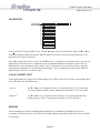
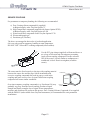
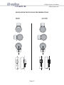
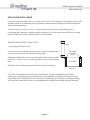
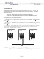
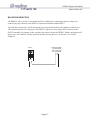
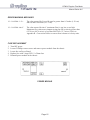
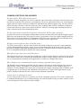
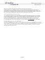
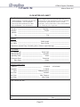
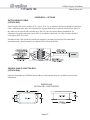
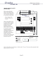
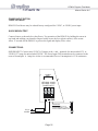
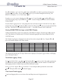
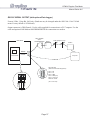
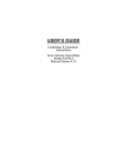
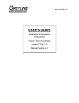
USER’S GUIDE
Installation & Operation
Instructions
Doppler Flow Meter
Model DFM-IV
Manual Series A.6
DFM-IV Doppler Flow Meter
Manual Series A.6
INDEX
Bench Test · · · · · · · · · · · · · · · · · · · · · · · · · · · · · · · · · · · · · · · · · · · · · · · · · · · · · · · 3
Connections· · · · · · · · · · · · · · · · · · · · · · · · · · · · · · · · · · · · · · · · · · · · · · · · · · · · · · · 3
Keypad System · · · · · · · · · · · · · · · · · · · · · · · · · · · · · · · · · · · · · · · · · · · · · · · · · · · · 4
Calibration Menu · · · · · · · · · · · · · · · · · · · · · · · · · · · · · · · · · · · · · · · · · · · · · · · · · · 5
Totalizer · · · · · · · · · · · · · · · · · · · · · · · · · · · · · · · · · · · · · · · · · · · · · · · · · · · · · · · · · 6
Signal Strength · · · · · · · · · · · · · · · · · · · · · · · · · · · · · · · · · · · · · · · · · · · · · · · · · · · · 6
Relay Status Display · · · · · · · · · · · · · · · · · · · · · · · · · · · · · · · · · · · · · · · · · · · · · · · · 7
Password · · · · · · · · · · · · · · · · · · · · · · · · · · · · · · · · · · · · · · · · · · · · · · · · · · · · · · · · · 7
Units /Mode · · · · · · · · · · · · · · · · · · · · · · · · · · · · · · · · · · · · · · · · · · · · · · · · · · · · · · 7
Calibration · · · · · · · · · · · · · · · · · · · · · · · · · · · · · · · · · · · · · · · · · · · · · · · · · · · · · · · 8
4-20mA Current Loop· · · · · · · · · · · · · · · · · · · · · · · · · · · · · · · · · · · · · · · · · · · · · · · 8
Damping · · · · · · · · · · · · · · · · · · · · · · · · · · · · · · · · · · · · · · · · · · · · · · · · · · · · · · · · · 8
Relay Parameters · · · · · · · · · · · · · · · · · · · · · · · · · · · · · · · · · · · · · · · · · · · · · · · · · · 9
Special Functions · · · · · · · · · · · · · · · · · · · · · · · · · · · · · · · · · · · · · · · · · · · · · · · · · 10
Reset Totalizer · · · · · · · · · · · · · · · · · · · · · · · · · · · · · · · · · · · · · · · · · · · · · · · · · · · 10
Sensor Mounting· · · · · · · · · · · · · · · · · · · · · · · · · · · · · · · · · · · · · · · · · · · · · · · · · · 11
Enclosure Installation · · · · · · · · · · · · · · · · · · · · · · · · · · · · · · · · · · · · · · · · · · · · · · 15
Synchronization · · · · · · · · · · · · · · · · · · · · · · · · · · · · · · · · · · · · · · · · · · · · · · · · · · 16
Backflow Rejection· · · · · · · · · · · · · · · · · · · · · · · · · · · · · · · · · · · · · · · · · · · · · · · · 17
Error/Warning Messages · · · · · · · · · · · · · · · · · · · · · · · · · · · · · · · · · · · · · · · · · · · 17
Fuse Replacement · · · · · · · · · · · · · · · · · · · · · · · · · · · · · · · · · · · · · · · · · · · · · · · · · 18
Troubleshooting · · · · · · · · · · · · · · · · · · · · · · · · · · · · · · · · · · · · · · · · · · · · · · · · · · 19
Common Questions and Answers· · · · · · · · · · · · · · · · · · · · · · · · · · · · · · · · · · · · · 22
Applications Hotline · · · · · · · · · · · · · · · · · · · · · · · · · · · · · · · · · · · · · · · · · · · · · · · 24
Product Return Procedure · · · · · · · · · · · · · · · · · · · · · · · · · · · · · · · · · · · · · · · · · · · 24
Flow Meter Data Sheet · · · · · · · · · · · · · · · · · · · · · · · · · · · · · · · · · · · · · · · · · · · · · 25
Warranty · · · · · · · · · · · · · · · · · · · · · · · · · · · · · · · · · · · · · · · · · · · · · · · · · · · · · · · 26
Appendix A – Options · · · · · · · · · · · · · · · · · · · · · · · · · · · · · · · · · · · · · · · · · · · · · 27
Data Logger · · · · · · · · · · · · · · · · · · · · · · · · · · · · · · · · · · · · · · · · · · · · · · · · · · · · · 32
RS232C Serial Output · · · · · · · · · · · · · · · · · · · · · · · · · · · · · · · · · · · · · · · · · · · · · 37
Specifications · · · · · · · · · · · · · · · · · · · · · · · · · · · · · · · · · · · · · · · · · · · · · · · · · · · · 39
Appendix B - Conversion Table · · · · · · · · · · · · · · · · · · · · · · · · · · · · · · · · · · · · · · 40
Pipe Charts · · · · · · · · · · · · · · · · · · · · · · · · · · · · · · · · · · · · · · · · · · · · · · · · · · · · · · 41
Calibration Record · · · · · · · · · · · · · · · · · · · · · · · · · · · · · · · · · · · · · · · · · · · · · · · · 44
IMPORTANT NOTE: This instrument is manufactured and calibrated to meet product specifications.
Please read this manual carefully before installation and operation. Any unauthorized repairs or
modifications may result in a suspension of the warranty.
Available in Adobe Acrobat pdf format
Page 2
DFM-IV Doppler Flow Meter
Manual Series A.6
QUICK BENCH TEST:
Connect Sensor as shown below, then Power. Test operation of the DFM-IV by holding the sensor in
one hand and rubbing your thumb or fingers briskly across the face (plastic surface) of the sensor.
Allow 15 seconds for the DFM-IV to process the signal and display a flow value.
CONNECTIONS:
POWER INPUT: The standard 115VAC model requires AC power input between 100 to 130 VAC
50/60Hz (2 amp fuse is recommended). No adjustments are necessary for voltages within this range.
Optional 230VAC requires power input between 200 to 260 VAC 50/60Hz. (See OPTIONS section of
this manual for connection of optional 12VDC or 24VDC power input).
IMPORTANT NOTE: To comply with CSA/NRTL electrical safety standards, AC power input and
relay connection wires must have conduit entry to the instrument enclosure.
SYNC
RCVR
N.O C N.C N.O C N.C N.O C N.C
RELAY 3
RELAY 2
RELAY 1
RX PU GND TX
4 - 20
RS 232
N.O C N.C N.O C N.C
RELAY 5
RELAY 4
A
B
INPUT
*
OPTIONAL
100-130VAC (50/60 Hz)
OPTIONAL:
200-260VAC (50/60 Hz)
L N G
VOLTAGE FREE
DRY CONTACTS
(BY CUSTOMER)
AC
GROUND STUD
IMPORTANT:
MUST CONNECT TO A
GOOD GROUND (<1 Ohm)
WITH 12 AWG CONDUCTOR
Page 3
*
IMPORTANT:
ATTACH CABLE
SHIELDS (SENSOR,
4-20mA, RS232)
THIS END ONLY
ALUMINUM CHASSIS
TMTR
DFM-IV Doppler Flow Meter
Manual Series A.6
KEYPAD SYSTEM
The DFM-IV has a simple 3-button calibration
system. Operating and calibration modes are shown
on the 16-digit alphanumeric display. The keypad is
used to move around the menu to calibrate the
DFM-IV, and to view operating mode and functions.
A beep is sounded as each key is pressed. If the
keypad is not used for 10 minutes, the DFM-IV will
automatically go to RUN mode. Use the keypad to
explore the Menu and become familiar with its
features.
MENU - FLOW CHART
The following diagram shows the DFM-IV Menu system. Arrows show the three directions to leave a
box. Pressing a corresponding keypad arrow will move to the next box in the direction shown. Move the
cursor (or underline) under numerals and increase or decrease numerals with the È and Ç keys.
At the bottom of each Menu column is a Store? Yes box. To store the calibration values permanently
(even through power failure), move the cursor under Yes and press the È or Ç key. If the È key is
pressed with the cursor under Store? no changes will be stored and the system will return to the top of
the Menu column.
Page 4
v
ft3
24 HR LOG
PASSWORD: 00
Page 5
- no more data -
255 Days
Dec 31/1999 ->
MIN Flow TIME
Daily MIN Flow
MAX Flow TIME
Daily MAX Flow
Daily AVERAGE
Daily TOTAL
Jan 01/2000 ->
SHOWS 24 Hr FORMAT
ONLY IF ENABLED
Relays: 1 2 3
SS
Tot: 1098
RUN
min
L
Yes
Hr
m3
d
brl
Hrs
Hrs
Interval: 4
Interval: 1
1 Sec
Interval:
Yes
Yes
*** STORING ***
Store?
26640 Hrs Left
Reset Log?
1 Min
2 Min
Interval:
Interval:
5 Min
Interval:
Interval: 10 Min
Interval: 30 Min
2 Sec
5 Sec
Interval:
Interval:
Interval: 10 Sec
WrapAround? Yes
Hrs
Interval: 30 Sec
Interval: 12 Hrs
Interval: 8
At:
03:02:16
Start
Event
1
Interval: 24 Hrs
Time
Trend
Log Site ID
Setup
HiAlm
03:02:16
%
StartJan 01/2000
Start
STOP
Formatted
1
StartJan 01/2000
Session No
RUN
Yes
10
100.0 %
0.00 %
*** STORING ***
Store?
Damping
20mA @
4mA @
Yes
100 ft3
5.0 ft3/s
LoAlm
*** STORING ***
Store?
R5
R4
R3
R2
R1on
R1 Function Off
Pipe ID 1.000 ft
MaxF 10.00 ft3/s
RELAY PARAMETERS
CALIBRATION
DATA LOGGING
*** STORING ***
Store?
s
IMG
Ft3 USG USMG IG>
cm
m
ft
in
Velocity
Flow
UNITS / MODE
Flow
R1OFF
0.00 ft3/s
R1on 100.0 ft3/s
Pulse
09
4.000
0.00 %
Yes
Slave
Yes
OPTIONAL FEATURES
*** STORING ***
Store?
Com 24 48 96 192
New Password: 00
Master
20mA ADJ 20.000
4mA ADJ
Simul
Defaults?
Yes
11:50:57
Reset Tot?
Time
Date Jan 01/2000
TAG
DFM-IV ver 2.67
SPECIAL FUNCTION
DFM-IV Doppler Flow Meter
Manual Series A.6
Calibration Menu
DFM-IV Doppler Flow Meter
Manual Series A.6
RUN
RUN
A scrolling display shows the units selected from the units selection
column, the mode of operation (VELOCITY or FLOW), the full
scale value for the large numeric display and the TOTALIZER value.
PASSWORD
Tot: 1098
SS
ft3
v
Relays: 1 2 3
TOTALIZER
From RUN use È key to display the totalizer value. The Totalizer
value is updated every 2 seconds with flow volume > 1 litre (0.264 USG). The Totalizer display will
show up to 10 digits and then overflows to 0 automatically.
Units: ft³, USG, IG, L
T: 9999999999
TOT:
0
Units = m³
T: 0283168470
TOT:
0
Press Ç key to return to RUN.
The Totalizer can be reset by going Æ to SPECIAL FUNCTIONS and È to Reset Tot?.
SIGNAL STRENGTH
SS
From TOTALIZER use È key to get to SS (Signal Strength /
Sensitivity).
Press Æ to position the cursor under the numeral. Use Ç or È to
increase or decrease signal strength. Minimum setting is '1'
Maximum setting is '9'.
Current
Signal Strength
Arrow
SS 5
Signal strength should be adjusted so that the 'Signal Strength
Arrow' meets the 'Ideal Marker' under normal flow conditions.
SS
Signal strength must pass the 'Minimum Marker' for the flow
meter to display flow.
SS
It is normal for Signal Strength to fluctuate and rise to full scale
under high flow conditions.
SS
Page 6
Minimum
Marker
v
v
v
Ideal
Marker
DFM-IV Doppler Flow Meter
Manual Series A.6
Relays 1 2 3 (Relay Status Display)
Displays state of each Relay. 1 2 3 4 5 - Reverse character indicates that the Relay is On (energized).
24 HR LOG
DFM-IV Flow Meters with optional Data Logger will display this menu. Refer to OPTIONS section.
PASSWORD
The password (a number from 00 to 99) prevents unauthorized access to the
CALIBRATION menu.
PASSWORD: 00
From RUN press Æ to get to PASSWORD.
PASSWORD: 00
Press Æ to place the cursor under the digit and È or Ç to enter your password.
Factory default Password is 00.
PASSWORD: 10
A new password can be stored by going to SPECIAL FUNCTIONS and È
to New Password.
UNITS /MODE
PASSWORD
CALIBRATION
UNITS / MODE
Flow
Velocity
ft
m
in
cm
Ft3 USG USMG IG>
IMG
s
m3
min
Store?
L
Hr
brl
d
Yes
*** STORING ***
Use Æ to get to UNITS / MODE, then È to get to Linear Units. Use Æ to move the cursor under the
required units.
Use È to get to Volume Units and then select units of Time and Flow or Velocity.
Flow mode displays flow rate in engineering units (e.g. gpm, litres/sec etc.)
Velocity mode displays flow velocity in units/time (e.g. ft/sec or m/sec)
When all units have been selected go to Store? then Æ to Yes and È or Ç to CALIBRATION.
Page 7
DFM-IV Doppler Flow Meter
Manual Series A.6
CALIBRATION
UNITS / MODE
CALIBRATION
RELAY PARAMETERS
Pipe ID 1.000 ft
MaxF 10.00 ft3/s
4mA @
0.00 %
20mA @
100.0 %
Damping
10
Store?
Yes
%
*** STORING ***
From CALIBRATION press È to Pipe ID and Æ to place the cursor under the digits and È or Ç to
change the numbers and decimal point. Pipe ID should be entered as the exact inside diameter of the
pipe where the sensor is mounted.
Press Æ to return the cursor to Pipe ID and È to MaxF. Set digits to the maximum flow rate in your
application. If maximum flow is unknown, enter an estimated maximum and observe actual flow to
determine the correct maximum value. (MaxF entry is required only to set 20mA output at a specific
flow rate and maximum flow in the optional data logger. MaxF setting has no effect on the DFM-IV
digital display, totalizer, or control relays).
4-20mA CURRENT LOOP
Some applications may require the 4-20mA output to be offset so that 4mA or 20mA correspond to flow
rates other than Zero and Maximum.
4mA at
use È or Ç to set % output for 4mA. It is adjustable from -5% (3.8mA) up to
15% lower than the 20mA setting. Adjustment resolution is 0.05% (0.01mA).
20mA at
use È or Ç to set % output for 20mA (down to 15% greater than the 4mA
setting and up to 300%). Adjustment resolution is 0.05% (0.01mA).
DAMPING
Increase damping to stabilize readings under turbulent flow conditions. Damping time shown in
percentage is the interval for a zero to full scale display change (maximum 99 percent). Factory default
is 20 percent.
Page 8
DFM-IV Doppler Flow Meter
Manual Series A.6
RELAY PARAMETERS
CALIBRATION
RELAY PARAMETERS
R1 Function Off
R1on
100 ft3
RELAY PARAMETERS
Pulse
Flow
R1on 100.0 ft3/s
R1OFF
0.00 ft3/s
R2
R3
R4
R5
Store?
Yes
*** STORING ***
Set Relays 1-3 (4-5 optional) to Off , Pulse or Flow.
Pulse
press È and set digits to the flow volume increment required between relay
pulses. Use this feature for remote samplers, chlorinators or totalizers.
Minimum time between pulses is 1 second and pulse duration is 350
milliseconds.
Flow
press È and set digits to the required On and Off set points. Use this feature for
flow control and alarms.
Page 9
DFM-IV Doppler Flow Meter
Manual Series A.6
SPECIAL FUNCTIONS
SPECIAL FUNCTION
DFM-IV ver 2.67
TAG
09
Date Jan 01/2000
Time
11:50:57
Reset Tot?
Yes
Defaults?
Yes
Simul
4mA ADJ
0.00 %
4.000
20mA ADJ 20.000
Master
Slave
New Password: 00
Com 24 48 96 192
Store?
Yes
*** STORING ***
Tag
shows software version installed
enter instrument Tag Number (0-9999)
Date
(with Optional Data Logger) use the È or Ç keys to change date as required
Time
(with Optional Data Logger) use the È or Ç keys to change time as required
Select Yes to reset totalizer
DFM-IV ver
Reset Tot? Yes
Press Æ 3 times to select Yes. Store to erase all user settings and return
instrument to factory default settings.
Simul 0.00%
exercises 4-20mA output, digital display and control relays. Simplifies
calibration of remote devices on the 4-20mA loop and checks set
point/operation of Relays calibrated in Flow mode. Go È for 100%.
4mA ADJ
Use to fine tune the 4mA and 20mA calibration of the 4-20mA output.
20mA ADJ
Adjustment range is +1mA to –1mA in 0.002mA steps
Important: The 4-20mA output will be forced to 4mA and 20mA respectively
during these adjustments.
Master or Slave Master or Slave selection for synchronization of multiple DFM-IV flow meters
(see Manual section SYNCHRONIZATION).
New Password
position cursor under digits and set new number between 00 and 99
Com 24 48 96 192 (Optional) set the baud rate of the DFM-IV RS232 output when equipped with
an optional data logger.
Defaults? Yes
Page 10
DFM-IV Doppler Flow Meter
Manual Series A.6
SENSOR MOUNTING LOCATION
The position of the sensor is one of the most important considerations for accurate Doppler flow
measurement. The same location guidelines apply to Doppler as most other types of flow meters.
Before permanently mounting a Doppler sensor onsite testing is recommended to determine optimum
mounting position. Use the sensor coupling compound (supplied with each Greyline flow meter, or
petroleum gel, acoustic compound or electrocardiograph gel). Take several readings around the axis of
the pipe and then at several points upstream and downstream from the selected position, checking for
consistent readings. Avoid high or low reading areas. Mount the sensor where consistent (average)
readings were obtained or continue testing on another pipe section.
VERTICAL OR HORIZONTAL PIPE - Vertical pipe
runs generally provide evenly distributed flow. On
Horizontal pipes and liquids with high concentrations
of gas or solids, the sensor should be mounted on the
side (3 or 9 o’clock position) to avoid concentrations
of gas at the top of the pipe, or solids at the bottom.
For liquids with minimal gas bubbles (e.g. potable
water) the sensor should be mounted on the top of a
horizontal pipe (12 o’clock position) to obtain the best
signal strength.
12 O' CL OCK P OS I T I ON W I T H
L OW GA S CONT E NT
3 O' CL OCK P OS I T I ON W I T H H I GH
GA S OR S OL I DS CONT E NT
V E R T I CA L P I P E U S U A L L Y
H A S E V E NL Y DI S T R I B U T E D F L OW
VELOCITY INCREASING DEVICES: Generally the sensor must be mounted away from flow
disturbances such as valves, pumps, orifice plates, venturis or pipe inlets and discharges which tend to
increase flow velocity. Velocity increasing devices often cause cavitation, or rapid release of gas
bubbles, and readings both up and downstream may show much higher velocity. As a guideline, mount
the sensor at least 20 diameters upstream or 30 diameters downstream from velocity increasing devices.
Required distance from a velocity increasing device will vary in applications depending on the flow
velocity and the characteristics of the liquid itself.
S E NS OR MOU NT S 6 DI A ME T E R S
U P S T R E A M OR 10 DOW NS T R E A M
F R OM A N E L B OW
F L OW
TURBULENCE INCREASING DEVICES: Elbows,
flanged connections and tees tend to introduce
desirable conditions of an evenly distributed flow
profile with some air or gases entrained in the flow.
Sensor mounting 6 pipe diameters upstream and 10
diameters downstream from these disturbances is
generally optimum.
The sensor is designed to mount longitudinally on a straight section of pipe. Do not attempt to mount it
on bends, elbows or fittings.
Page 11
DFM-IV Doppler Flow Meter
Manual Series A.6
SENSOR MOUNTING
Prepare an area 2" wide by 4" long (50mm x 100mm) for sensor bonding by removing loose paint, scale
and rust. The objective of site preparation is to eliminate any discontinuity between the sensor and the
pipe wall, which would prevent acoustical coupling.
A PC3 Sensor Mounting Kit is supplied with each Greyline flow meter. It includes recommended
coupling compound in a plastic applicator and a stainless steel mounting bracket with adjustable pipe
straps.
SENSOR
PIPE
PIPE
Mount the PC3 pipe clamp as illustrated on pipes
0.6" / 15 mm OD or larger. Stainless steel bands are
included for mounting on pipes up to 32" / 81 cm OD.
END VIEW
Additional stainless steel bands (by customer) may be
combined to mount on pipes up to 180" / 4.5 m OD.
SENSOR
ADJUSTABLE
STAINLESS
STEEL STRAP
PIPE
Page 12
PIPE
DFM-IV Doppler Flow Meter
Manual Series A.6
SENSOR COUPLING
For permanent or temporary bonding, the following are recommended:
a) Dow Corning silicon compound #4 (supplied)
Additional supply: order Greyline Option CC
b) High Temperature compound (supplied with Sensor Option SE3H)
Additional supply: order Greyline Option AP-1W
c) Water-based sonic compound: Order Greyline Option CC30
d) Electrocardiograph gel
e) Petroleum gel (Vaseline)
The above are arranged in their order of preferred application.
d & e are only good for temporary bonding at room temperature.
DO NOT USE: Silicon RTV caulking compound (silicon rubber).
M
CO
SENSOR
D
UN
O
P
Use the PC3 pipe clamp (supplied) as illustrated above or
use a loop of electrical tape for temporary mounting.
Apply silicon coupling compound #4 to the coloured
face of the sensor. A bead, similar to toothpaste on a
toothbrush, is ideal. Do not overtighten (crush the
sensor).
The sensor must be fixed securely to the pipe with coupling material
between the sensor face and the pipe. Sensor installation with
excessive coupling compound can result in gaps or voids in the
coupling and cause errors or loss of signal. Insufficient coupling
compound will create similar conditions.
COMPOUND
SENSOR
PIPE
Over time temporary coupling compounds (e.g. Petroleum Gel) may TAPE OR
CLAMP
gradually sag away from the sensor resulting in reduced signal
strength and finally complete loss of signal. Warm temperatures,
moisture and vibration will accelerate this process. Dow Corning Silicone Compound #4 as supplied
with the DFM-IV (and available from Greyline Instruments) is recommended for semi-permanent
installations.
Page 13
DFM-IV Doppler Flow Meter
Manual Series A.6
SENSOR MOUNTING/COUPLING RECOMMENDATIONS
GOOD
BAD
Page 14
DFM-IV Doppler Flow Meter
Manual Series A.6
ENCLOSURE INSTALLATION
Locate the enclosure within 20 ft (6 m) of the sensor (500 ft -150 m optional). The enclosure can be wall
mounted with the four mounting screws (included) or panel mounted with Option PM Panel Mount kit
from Greyline Instruments.
Avoid mounting the enclosure in direct sunlight to protect the electronics from damage due to
overheating and condensate. In high humidity atmospheres, or where temperatures fall below freezing,
Option TH Enclosure Heater and Thermostat is recommended.
NEMA4X (IP66) WITH CLEAR COVER
COVER
1. Open hinged enclosure cover.
2. Insert #8 screws (supplied) through the four enclosure mounting holes
to secure the enclosure to the wall or mounting stand.
Additional conduit holes can be cut in the bottom of the enclosure when
required. Use a hole saw or Greenlee-type hole cutter to cut the required
holes.
ENCLOSURE
MOUNTING
HOLES
ENCLOSURE
DO NOT make conduit/wiring entries into the top of the enclosure.
END VIEW
Note: This non-metallic enclosure does not automatically provide grounding between conduit
connections. Grounding must be provided as part of the installation. Ground in accordance with the
requirements of the National Electrical Code. System grounding is provided by connecting grounding
wires from all conduit entries to the steel mounting plate or another point which provides continuity.
Page 15
DFM-IV Doppler Flow Meter
Manual Series A.6
SYNCHRONIZATION
Synchronization may be required to prevent interference (readings with no flow or “cross talk”) in
applications where more than one DFM-IV Doppler sensor is used in close proximity. Synchronize
DFM-IV flow meters if:
- sensors from separate DFM-IV flow meters are mounted on the same pipe
- extended sensor cables from separate DFM-IV flow meters are run in the same conduit
To synchronize two or more DFM-IV flow meters:
1. Choose one DFM-IV as a MASTER. Go to the SPECIAL FUNCTIONS menu, select Master and
Store? Yes.
2. All other DFM-IV’s must be SLAVES. Go to the SPECIAL FUNCTIONS menu, select Slave and
Store? Yes.
3. Connect SYNC + of the “Master” unit to SYNC + of the first “Slave”. Connect SYNC + of the first
Slave to SYNC + of the second Slave and so on. Ensure that all units have a common Ground by
wiring all GND – terminals together as illustrated:
MASTER
TMTR
SYNC
SLAVE
TMTR
SYNC
SLAVE
TMTR
SYNC
WARNING: Only one DFM-IV in the group can be in “MASTER” mode.
If all units are returned to “MASTER” status, the “SYNC” wiring must be disconnected.
Page 16
DFM-IV Doppler Flow Meter
Manual Series A.6
BACKFLOW REJECTION
The DFM-IV can be forced to zero under backflow conditions by connecting external, voltage free
control relay (dry contacts) to the DFM-IV connection terminals marked INPUT.
Typically the external relay will be energized or de-energized in tandem with a pump or control valve.
The external relay must be voltage free (the DFM-IV generates a low-voltage DC current across the
INPUT terminals). In response to the external relay contact closure the DFM-IV display and outputs will
drop to zero, the Totalizer will not increment and the message Backflow Rejection will be
displayed.
DFM-IV
A
EXTERNAL RELAY
(VOLTAGE FREE
DRY CONTACTS
BY CUSTOMER)
B
INPUT
Page 17
DFM-IV Doppler Flow Meter
Manual Series A.6
ERROR/WARNING MESSAGES
E: ILLEGAL I.D.
The value entered for Pipe ID must be greater than 0.5 inches (1.26 cm)
and less than 180 inches (457.3 cm).
E: ILLEGAL MaxF
The value entered for MaxF (maximum flow) is too low or too high.
Maximum flow value must compute (using pipe ID) a velocity greater than
0.25 ft/sec (0.076 m/sec) or less than 40.0 ft/sec (12.2 m/sec). Refer to
Appendix B - Conversion Tables to convert from volume to velocity units.
FUSE REPLACEMENT
1.
2.
3.
4.
5.
Turn OFF power
Loosen 2 Phillips corner screws and remove power module from the chassis.
Locate fuse on Power Board
Replace fuse with 2 Amp/250V, 5 x 20mm fuse
Reinstall power module in the chassis.
POWER MODULE
Page 18
DFM-IV Doppler Flow Meter
Manual Series A.6
FIELD TROUBLESHOOTING
Possible Causes:
Corrective Action:
METER READING LOWER THAN EXPECTED
Calibration Error
· Review UNITS/MODE menu and Pipe ID
Lower flow rate than expected
· Investigate pump/valves. Compare velocity
with alternate instrument
Signal not penetrating far enough into the flow
stream
· Increase sensitivity
Laminar flow condition or high solids/bubbles
content in liquid
· Remount Sensor at 12 o'clock position on
horizontal pipe
Improper mounting of sensor
· Reinstall Sensor with careful application of
Coupling Compound
Pipe is not full
· Remount Sensor on vertical pipe
METER READING WHEN THERE IS NO FLOW
Vibration on pipe
Local electrical noise
· Relocate sensor closer to elbows or flow
disturbances
· Install in another location
· Ensure all Flowmeter wiring is in METAL
conduit and sensor shield is properly grounded.
· Ensure correct power input Ground connection
(<1 ohm resistance).
· Ensure 4-20mA Shield connected to
Instrument Ground stud.
· Reduce DFM Sensitivity setting.
Cross talk between two or more DFM-IV
flowmeters on same pipe
· Turn OFF one flowmeter or follow
synchronization procedure for two or more
DFM-IV Flowmeters.
Variable Speed Drive interference
· Follow Drive manufacturers wiring and
Grounding instructions
· Relocate Flowmeter electronics, Sensor and
wiring away from VSD
Page 19
DFM-IV Doppler Flow Meter
Manual Series A.6
Possible Causes:
Valve leak or Reverse flow
Corrective Action:
· Test Valve. Relocate Sensor farther from valve
· Use Backflow Rejection
Sensor connections incorrect
· Refer to Connections diagram
METER READING ERRATIC
Sensor mounted too close to valve, pump or
elbow
· Change sensor placement. Recommended 6-10
diameters from elbows, and 30 diameters from
pumps, controlling valves, orifice plates,
nozzles or open pipe discharge
NO FLOW INDICATION
SS Signal Strength/Sensitivity set too low
· Increase SS/Sensitivity
Not enough suspended particles or gases in the
fluid
· Relocate sensor in more turbulent pipe section.
Mount sensor at 12 o'clock position on
horizontal pipe
Coupling compound washed out, or sensor loose
on pipe
· Remount sensor
Slave selected in SPECIAL FUNCTIONS
· Select Master in SPECIAL FUNCTIONS
menu.
menu with no Synchronization input from
Master.
Power interruption. No flow.
· Use Dow Corning Silicone #4
· Check fuse/breaker. Confirm flow
METER READING TOO HIGH
Calibration error
· Review UNITS/MODE menu and Pipe ID
Vibration or noise on the pipeline
· Decrease Sensitivity. Install in another
location.
Pipe is not full
· Remount Sensor on vertical pipe
Nearby velocity increasing device (pump, valve,
orifice plate)
· Relocate sensor >30 pipe diameters from
velocity increasing device
Local electrical noise
· Ensure all Flowmeter wiring is in METAL
conduit and sensor cable shield is connected to
Ground stud
Page 20
DFM-IV Doppler Flow Meter
Manual Series A.6
Possible Causes:
Variable Speed Drive interference
Corrective Action:
· Follow Drive manufacturers wiring and
Grounding instructions
· Relocate Flowmeter electronics, Sensor and
wiring away from VSD
METER READING DOES NOT TRACK FLOW
Sensor and GND wires reversed or not properly
connected
Improper AC power input Ground
· Check Sensor connections
· Use direct connection with 12 AWG wire to
nearest Ground pole (<1 ohm resistance).
Page 21
DFM-IV Doppler Flow Meter
Manual Series A.6
COMMON QUESTIONS AND ANSWERS
The pipe vibrates. Will it affect the flow meter?
Common vibration frequencies are far lower than the sonic frequencies used by the Greyline flow meter,
and will not normally affect accuracy or performance. However, applications where very weak Doppler
signal is present (when sensitivity is adjusted to maximum and signal strength is low), accuracy may be
affected by pipe vibration, or the flow meter may show readings under no-flow conditions. Attempt to
relocate the sensor on a pipe section where vibration is reduced, or arrange pipe mounting brackets to
reduce vibration at the sensor mounting location.
The flow meter must be installed in a high noise environment. Will this affect operation?
Greyline flow meters are designed to discriminate between environmental noise and the Doppler signal.
High noise environments may affect the flow meter’s performance where low signal strength and/or low
flow velocities are being measured. If adjustment of the flow meter sensitivity does not eliminate noise
interference a non-acoustic flow meter should be considered for the application.
Will pipe corrosion affect accuracy of the flow meter?
Yes. Rust, loose paint etc. must be removed from the outside of the pipe to provide a clean mounting
position when installing a Doppler sensor. Severe corrosion/oxidation on the inside of the pipe may
prevent the Doppler signal from penetrating into the flow. If the pipe cannot be cleaned, a spool piece
(PVC recommended) should be installed for sensor mounting.
What effect do pipe liners have on the flow meter?
The air gap between loose insertion liners and the pipe wall prevent the Doppler signal from entering the
flow. Better results can be expected with bonded liners such as cement, epoxy or tar, however an on site
test is recommended to determine if the application is suitable for a Doppler flow meter.
Why is Doppler only recommended for liquids containing suspended solids or gases?
The Doppler sensor transmits sound into the flow stream which must be reflected back to the sensor to
indicate flow velocity. Gas bubbles or suspended solids act as reflectors for the Doppler signal. As a
guideline, Greyline Doppler flow meters are recommended for liquids containing solids or bubbles with
a minimum size of 100 microns and a minimum concentration of 75 ppm. Most applications (except
potable, distilled or deionized water) will meet this minimum requirement.
Can the sensor be submerged in water?
Yes, for short periods of time or by accident, but not for continuous operation. The sensor is constructed
to withstand submersion to 10 psi without damage, but external liquid moving in contact with the sensor
can be interpreted as flow and cause false readings.
Page 22
DFM-IV Doppler Flow Meter
Manual Series A.6
What is the purpose of the Signal Strength Display and Sensitivity adjustment?
Doppler signals of low strength (left of the X on the SS signal strength display) are not accepted or
processed by the instrument. This feature assists in rejection of environmental noise and vibration. For
optimum noise rejection the sensitivity control should be adjusted so that signal strength is to the right of
the X on the signal strength display with flow and to the left of the X with no flow.
Can I change the length of the sensor cable?
Yes. Technological advances in Greyline Doppler design allow cable lengths up to 500 ft (152 m) with
no loss of signal strength. Extended cable (Greyline Option XC) should be installed in rigid or flexible
conduit for mechanical protection. Use only Greyline shielded coaxial pair (RG174U) cable. Cable
junctions should be made through a terminal block and housed in a watertight metal junction box
(Greyline Option JB). BNC coaxial connectors (TV cable type) are not recommended for cable splices.
Does the DFM-IV require periodic recalibration?
No. DFM-IV calibration does not drift over time. The solid state sensor has no moving parts to wear and
affect calibration. The Doppler flow technique generates an ultrasonic signal proportional to the velocity
of flow. All Greyline timing/counting circuits use crystal-controlled frequency references to eliminate
any drift in the processing circuitry.
Page 23
DFM-IV Doppler Flow Meter
Manual Series A.6
APPLICATIONS HOTLINE
For applications assistance, advice or information on any Greyline Instrument contact your Sales
Representative, write to Greyline or phone the Applications Hotline below:
United States:
Canada:
Toll Free:
Email:
Web Site:
Tel: 315-788-9500
Tel: 613-938-8956
888-473-9546
[email protected]
www.greyline.com
Fax: 315-764-0419
Fax: 613-938-4857
Greyline Instruments Inc.
Canada
16456 Sixsmith Drive
Long Sault, Ont. K0C 1P0
USA:
407 County Route 46
Massena, NY 13662
PRODUCT RETURN PROCEDURE
Instruments may be returned to Greyline for service or warranty repair. Before shipping a product to the
factory please contact Greyline by telephone or Fax to obtain an RMA number (Returned Merchandise
Authorization). This ensures fast service and correct billing or credit.
When you contact Greyline please have the following information available:
1.
2.
3.
4.
5.
Model number / Software Version
Serial number
Date of Purchase
Reason for return (description of fault or modification required)
Your name, company name, address, phone and fax number
After obtaining an RMA number please ship the product to the appropriate address below:
Canadian and International
Customers:
USA
Customers:
Greyline Instruments Inc.
16456 Sixsmith Drive
Long Sault, Ont. K0C 1P0
Greyline Instruments Inc.
407 County Route 46
Massena, NY 13662
RMA#
RMA#
Page 24
DFM-IV Doppler Flow Meter
Manual Series A.6
FLOW METER DATA SHEET
Greyline Instruments Inc.
0
16456 Sixsmith Dr., Long Sault, Ont. K0C 1P0
Tel: 613-938-8956 / Fax: 613-938-4857
0
407 County Route 46, Massena NY 13662
Tel: 315-788-9500 / Fax: 315-764-0419
Please complete and return this form to Greyline. It is
important. We use this information to check our database
for performance of Greyline flow meters in similar
applications, and to provide advice and recommendations
to you. Thanks for your cooperation.
Contact: ________________________________ Title/Dept.: _________________________
Company: ___________________________________ Project: _________________________
Address: ____________________________________________________________________
Tel: _____________________________________ Fax: _________________________
SENSOR:
Model/Type: _____________________________ Cable Length: _________________________
Elec. Class: _____________________________ Type of Pump: _________________________
Distance from nearest Pump, Controlling Valve, Orifice or open Discharge: ___________________
INSTRUMENT:
Model/Type: _________________________ Power Input: _________________________
Calibrated Range: ___________________________ Indication: _________________________
Operating Temp.: ___________________________
Alarm: _________________________
Enclosure Class: __________________________ Pulse/Unit: _________________________
Elec. Class: _____________________________ Output: _________________________
SERVICE CONDITIONS:
0 Vertical
Pipe ID: _______________________________
Pipe Mat'l: _______________________________
0 Horizontal
% Solids: _________________________
Fluid: __________________________ Material Build-up: _________________________
Oper. Flow: _________________________________ Vibration: _________________________
Max. Flow: ____________________________ Max. Pressure: _________________________
Min. Flow: _____________________________
Max. Temp: _________________________
Notes / Sketch Pipe Run:
By: _______________________________________________
Page 25
Date: ___________________
DFM-IV Doppler Flow Meter
Manual Series A.6
LIMITED WARRANTY
______________________
Greyline Instruments warrants, to the original purchaser, its
products to be free from defects in material and workmanship for
a period of one year from date of invoice. Greyline will replace
or repair, free of charge, any Greyline product if it has been
proven to be defective within the warranty period. This warranty
does not cover any expenses incurred in the removal and
re-installation of the product.
If a product manufactured by Greyline should prove defective
within the first year, return it freight prepaid to Greyline
Instruments along with a copy of your invoice.
This warranty does not cover damages due to improper
installation or handling, acts of nature, or unauthorized service.
Modifications to or tampering with any part shall void this
warranty. This warranty does not cover any equipment used in
connection with the product or consequential damages due to a
defect in the product.
All implied warranties are limited to the duration of this
warranty. This is the complete warranty by Greyline and no
other warranty is valid against Greyline. Some states do not
allow limitations on how long an implied warranty lasts or
limitation of incidental or consequential damages, so the above
limitations or exclusions may not apply to you.
This warranty gives you specific legal rights, and you may also
have other rights which vary from state to state.
Greyline Instruments Inc.
Page 26
DFM-IV Doppler Flow Meter
Manual Series A.6
APPENDIX A – OPTIONS
EXTRA SENSOR CABLE
(OPTION DXC)
Each Greyline flow meter includes 20 ft / 6m (or 50 ft / 15 m optional) continuous shielded coaxial pair
cable. Additional cable and Cable Junction Box (Option DJB) may be ordered with the Flow Meter, or
the cable may be spliced and extended up to 500 ft (152m) as required during installation. No
adjustment is required when the sensor cable is extended or shortened. Use only Greyline shielded
coaxial pair (RG174U) cable.
Extended sensor cable should be installed in conduit for mechanical protection. Recommended
installation with a metal junction box (Option DJB) is illustrated below:
SENSOR CABLE JUNCTION BOX
(OPTION DJB)
Optional Watertight steel NEMA4 Junction Boxes with terminal strips are available from Greyline
Instruments.
DIMENSIONS
OPTION DJB - JUNCTION BOX
Page 27
DFM-IV Doppler Flow Meter
Manual Series A.6
When connected through
Intrinsic Safety Barriers, the
Greyline Sensor Model SE3 is
CSA certified for installation
in a hazardous location rated:
Class I, Groups C,D
Class II, Groups E,F,G
Class III
Intrinsic Safety Barriers may
be ordered with the Greyline
instrument and are supplied
mounted in the Greyline
instrument enclosure.
Replacement barrier fuses
(Part No. ISB- 011239) may
be purchased separately. The
Instrument Enclosure
containing the 2ISB Intrinsic
Safety Barriers must be
installed in a non-hazardous
location. The Sensor,
connecting cable and Junction
boxes may be located in the
hazardous rated area.
4
2
SENSOR INTRINSIC SAFETY
(OPTION 2ISB)
4
2
3
1
INTRINSIC SAFETY BARRIER
TMTR
3
1
INTRINSIC SAFETY BARRIER
SYNC
RCVR
N.O C N.C N.O C N.C N.O C N.C
RELAY 3
RELAY 2
RELAY 1
RX PU GND TX
4 - 20
RS 232
N.O C N.C N.O C N.C
RELAY 5
RELAY 4
A
B
INPUT
OPTIONAL
L N G
VOLTAGE FREE
DRY CONTACTS
(BY CUSTOMER)
AC
NON-HAZARDOUS LOCATION
NOTE:
BARRIER-EQUIPPED UNITS
ARE FACTORY-WIRED WITH
GROUND THROUGH THE
INSTRUMENT CHASSIS.
POWER INPUT GROUND
MUST BE CONNECTED TO A
GOOD GROUND (<1 Ohm) WITH
A 12 AWG CONDUCTOR
HAZARDOUS LOCATION
CLASS I, GROUPS C,D
CLASS II, GROUPS E,F,G
CLASS III
SENSOR
REPLACEMENT FUSE ASSEMBLY
ORDER PART NO. ISB-011239 (160mA)
Intrinsic Safety Barrier Specifications: Certified, rated 9.3V max, 25 ohms min. (Recommended: Stahl
Model 9001/02-093-390-10).
Page 28
DFM-IV Doppler Flow Meter
Manual Series A.6
ENCLOSURE HEATER AND THERMOSTAT - Option TH
Instruments can be factory-equipped with an Enclosure Heater and Thermostat. The Thermostat is
factory set to turn ON at 40°F (4.5°C) and OFF at 60°F (15.5°C). Power consumption is 15 Watts.
FACTORY CONNECTED
TO AC POWER SUPPLY
ENCLOSURE SUNSCREEN - Option SCR
Do not mount instrument electronics in direct sunlight. Overheating will reduce the life of electronic
components and condensate may form during the heat/cool cycles and cause electrical shorts.
11" / 280 mm
Note:
11"
Exposure to direct sunlight can cause
280 mm
overheating and moisture condensation
which will reduce the operating life of
electronics.
Protect Instruments from direct sunlight
with this iridite finished aluminum sun
screen (Greyline Option SCR).
Seal conduit entries with caulking
compound to further reduce moisture
condensation.
Page 29
5"
127 mm
DFM-IV Doppler Flow Meter
Manual Series A.6
POWER INPUT OPTION
12VDC OR 24VDC
DFM-IV Flow Meters may be ordered factory-configured for 12VDC, or 24VDC power input.
QUICK BENCH TEST:
Connect Sensor as shown below, then Power. Test operation of the DFM-IV by holding the sensor in
one hand and rubbing your thumb or fingers briskly across the face (plastic surface) of the sensor.
Allow 15 seconds for the DFM-IV to process the signal and display a flow value.
CONNECTIONS:
POWER INPUT: Connect only 12VDC/0.54 Amps to the + and - terminals for units marked 12V, or
24VDC/0.27 Amps for units marked 24VDC. The Power Input GND terminal must be connected to the
nearest Ground pole. A 1 amp fuse in line is recommended. Power Consumption is 6.5 W continuous.
12 AWG
MAX
OPTIONAL 24VDC
OPTIONAL 12VDC
POWER INPUT
GND
12V or
24VDC
IMPORTANT:
MUST CONNECT TO A
GOOD GROUND (<1 Ohm)
WITH 12 AWG CONDUCTOR
1 AMP FUSE
Page 30
DFM-IV Doppler Flow Meter
Manual Series A.6
INSERTION FLOW SENSOR
(OPTION ISE)
Insertion Depth: 1/8th pipe inside diameter plus 3/4" (20 mm).
20' (6 m) CONTINUOUS
SHIELDED COAXIAL PAIR
(50' / 15 m OPTIONAL)
MARKER
POINTS
UPSTREAM
ADJUSTABLE
SWAGE-LOCK
FITTING
Orientation: Screw head marks the active face and should point
upstream ±5°.
Average Flow Rate: Before permanent tightening of swage lock fitting,
the probe can be inserted to variable depths to determine the flow
profile. Theoretical average flow occurs at 1/8 pipe diameter.
Installation Procedure: Install a 1" NPT Female Nipple on the Pipe.
Insert probe. Tighten swage lock until it just grips the Probe - then
tighten 3/4 of a turn. Do not use above 100 psi.
1" NPT
6", 12" OR
SPECIAL
ORDER
316
STAINLESS
STEEL
PVC
HIGH TEMPERATURE SENSOR
(OPTION SE3H)
Mount with coupling compound and stainless steel pipe clamp
(supplied). Protect Sensor cable from contact with hot pipes.
OVERALL LENGTH 13" (330 mm)
STANDARD
50' (15 m) OPTIONAL
5/16" (8 mm) O.D.
HIGH TEMPERATURE
SENSOR MODEL SE3H
SE3H Specifications:
Operating Temperature:
Minimum Pipe Diameter:
Maximum Pipe Diameter:
Operating Frequency:
Exposed Materials:
Sensor Cable:
-40° to 302°F (-40° to 150°C)
0.5" (12.5 mm) ID, 0.6" (15 mm) OD
180" (4.5 m) O.D.
640 KHz
stainless steel with epoxy face
20 ft (6 m) RG174U shielded coaxial pair
Page 31
DFM-IV Doppler Flow Meter
Manual Series A.6
Data Logger Menu (Optional)
PASSWORD: 00
UNITS / MODE
DATA LOGGING
RUN
Session No
STOP
Setup
1
Log Site ID
1
Formatted Trend
Time
StartJan 01/2000
Event
Start 03:02:16
StartJan 01/2000
HiAlm
Interval: 24 Hrs
Start
At:
Interval: 12 Hrs
Interval: 30 Sec
03:02:16
Interval: 10 Sec
Interval: 8 Hrs
Interval:
5 Sec
Interval:
2 Sec
Interval:
1 Sec
Interval: 30 Min
Interval: 4 Hrs
Interval: 10 Min
Interval: 1 Hrs
Interval:
5 Min
Interval:
2 Min
Interval:
1 Min
WrapAround? Yes
Reset Log?
Yes
26640 Hrs Left
Store?
Yes
*** STORING ***
Page 32
LoAlm
5.0 ft3/s
DFM-IV Doppler Flow Meter
Manual Series A.6
DATA LOGGING (Optional)
Setup
From RUN STOP SETUP press Æ to SETUP and then È to Log Site ID 0. Press Æ to position the
cursor under the numeral and È or Ç to change the numerals. The “Site ID” number is retained with
data logging sessions to identify logs stored from different locations.
Formatted Data
Press È from Log Site ID and press È from Formatted .
“Formatted” data stores a summary of flow readings over a user-selectable time period. The
summary includes:
DATE and TIME
Interval TOTAL
Interval AVERAGE
Interval MAX FLOW
Interval MAX FLOW TIME
Interval MIN FLOW
Interval MIN FLOW TIME
From Formatted press È to Start MMM DD/YYYY (eg: Jan 01/2000). Press Æ to position the
cursor and then È or Ç to set the Month, Day and Year that logging will Start. Press Æ to return to
Start.
Press È to Start (time) and Æ to position the cursor under the time column HH/MM/SS (24 hour
clock in Hours/minutes/seconds, eg: 23:02:16) and then È or Ç to set the logging start Time. Press
Æ to return to Start .
Press È to Interval and Æ to the Hrs column. Press È or Ç to select the flow logging interval.
Choose from:
24 Hrs, or 12 Hrs, or 8 Hrs, or 4 Hrs, or 1 Hrs
Press Æ to return to Interval. Press È and the DFM-IV will report xxxxx Hrs Left indicating
the amount of logging time available with your current set-up. You can also press Ç to return to
previous menu items and make changes.
Press È to WrapAround Yes?. Press Æ to Yes? and È to enable the logging wrap function. In
WrapAround mode the oldest data will be overwritten by the newest. If WrapAround is not enabled the
logger will stop when its memory becomes full.
Page 33
DFM-IV Doppler Flow Meter
Manual Series A.6
Press È to Reset Log? Yes. Press Æ to Yes and then È to reset the Log and erase all previous
sessions and stored values. Or press È from Reset Log? to retain existing data in the Log. The
DFM-IV will display “xxxxx Hrs/Days Left”.
From the xxxxx Hrs Left display press È to Store? Yes. Press Æ to Yes and then È to save
your Data Logging setup, or press È from Store? to cancel changes made above and exit without
storing changes.
From the Data Logging Store? Yes prompt the menu will return to RUN STOP SETUP. Press Æ to
position the cursor under RUN and press È to activate the Data Logger to start at your selected start Date
and Time. The DFM-IV will display SESSION NO. x. Press È to return to DATA LOGGING.
Viewing FORMATTED Data Logs on the DFM-IV Display
24 Hour Formatted logs can be viewed directly on the DFM-IV display. From RUN press Æ to 24 HR
LOG. This function is available only if 24 Hour Formatted logging has been Stored from the DATA
LOGGING menu.
The 24 Hour Log Report is designed to be read one line at time using the Æ key. Using the È or Ç
keys will return the display to the Date column.
TODAYS DATE
DAILY TOTAL
DAILY AVERAGE
MAX FLOW
MAX FLOW TIME
MIN FLOW
MIN FLOW TIME
PREVIOUS DATE
“
“
“
“
“
“
PREVIOUS DATE
“
“
“
“
“
“
PREVIOUS DATE
“
“
“
“
“
“
PREVIOUS DATE
“
“
“
“
“
“
PREVIOUS DATE
“
“
“
“
“
“
The current day plus the past 255 days of data can be displayed. (Greyline Logger software will display
up to 1300 days of data.)
Trend Data Logging - Setup
From RUN STOP SETUP press Æ to SETUP and then È to Log Site ID 0. Press Æ to position the
cursor under the numeral and È or Ç to change the numerals. The “Site ID” number is retained with
data logging sessions to identify logs stored from different locations.
From Log Site ID press È to Formatted Trend and press Æ to position the cursor under
Trend. Then press È to select Time based logging.
‘Time’ based Trend Logging
Time based logging allows you to choose Start and Stop times and a logging interval.
Page 34
DFM-IV Doppler Flow Meter
Manual Series A.6
From Time press È to Start MMM DD/YYYY (eg: Jan 01/2000). Press Æ to position the cursor
and then È or Ç to set the Month, Day and Year that logging will Start. Press Æ to return to Start.
Press È to Start (time) and Æ to position the cursor under the time column HH/MM/SS (24 hour
clock in Hours/minutes/seconds, eg: 23:02:16) and then È or Ç to set the logging start Time. Press
Æ to return to Start .
Press È to Interval and Æ to the Sec/Min column. Press È or Ç to set the logging time interval.
Choose:
30 Sec
10 Sec
5 Sec
2 Sec
1 Sec
30 Min
10 Min
5 Min
2 Min
1 Min
Press Æ to return to to Interval and È to Reset Log? To erase all existing data in the log press Æ
to Yes and È. To keep existing data in the Log press È from Reset Log? If you have made changes
to the Start Date, Time or Interval, the data logger will automatically start a new “session”. The DFM-IV
will display “xxxxx Hrs/Days Left”.
From the xxxxx Hrs Left display press È to Store? Yes. Press Æ to Yes and then È to save
your Data Logging setup, or press È from Store? to cancel changes made above and exit without
storing changes.
From the Data Logging Store? Yes prompt the menu will return to RUN STOP SETUP. Press Æ to
position the cursor under RUN and press È to activate the Data Logger to start at your selected start Date
and Time. The DFM-IV will display SESSION NO. x. Press È to return to DATA LOGGING.
‘Event’ based Trend Logging
Event based logging stores data points only when a High or Low flow set point has been reached.
With cursor under Event press È to HiAlm LoAlm . HiAlm will log points above a selectable flow
rate, while LoAlm will log points below a selectable flow rate. Position the cursor under HiAlm or
LoAlm and press È to the At: prompt. Press Æ to the numerals column and press È or Ç to set flow
alarm logging set point. Press Æ to return to At:.
Page 35
DFM-IV Doppler Flow Meter
Manual Series A.6
Press È to Interval and Æ to the Sec/Min column. Press È or Ç to set the logging time interval.
Choose:
30 Sec
10 Sec
5 Sec
2 Sec
1 Sec
30 Min
10 Min
5 Min
2 Min
1 Min
Press Æ to return to Interval and press È to Reset Log? To erase all existing data in the log press
Æ to Yes and È. To keep existing data in the Log press È from Reset Log? If you have made
changes to the Start Date, Time or Interval, the data logger will automatically start a new “session”. The
DFM-IV will display “xxxxx Hrs/Days Left”.
From the xxxxx Hrs Left display press È to Store? Yes. Press Æ to Yes and then È to save
your Data Logging setup, or press È from Store? to cancel changes made above and exit without
storing changes.
From the Data Logging Store? Yes prompt the menu will return to RUN STOP SETUP. Press Æ to
position the cursor under RUN and press È to activate the Data Logger to start. The DFM-IV will
display SESSION NO. x. Press È to return to DATA LOGGING.
Logging "Sessions"
Each time you select STOP in the DATA LOGGING menu, the Data Logger stores the current data in
memory as a "SESSION NO" automatically numbered from "1" to "10". If you resume logging by
selecting RUN, the Data Logger will report that a new logging session is started and titled "SESSION
NO xx". When you download the logger files to your PC using Greyline Logger software, each Session
will open as a separate graph/table titled "Greyline Data Log xx".
Important:
If you STORE instrument calibration changes under the UNITS/MODE or CALIBRATON menus, STOP
the data logger and select RUN again to start a new logging Session with your new calibration values.
Page 36
DFM-IV Doppler Flow Meter
Manual Series A.6
RS232C SERIAL OUTPUT (with optional Data Logger)
Format: 8 Bits, 1 Stop Bit, No Parity. (Baud rate may be changed under the SPECIAL FUNCTIONS
menu. Factory default is 19200 baud).
Output connector is DB9-Female. Use the cable supplied for connection to a PC Computer. Use the
cable and optional Null Modem NM-DB9M/DB25M for connection to a modem.
NULL MODEM
Option
NM-DB9M/DB25M
RS232
20' (6 m) cable
Greyline
included
Instrument
Modem
Computer
Wired as DCE
(Data Communication Equipment)
Detail
9
8
7
6
Detail
Public Telephone Lines
DB25F
DB25M
Modem
DB9F
DB9M
INCLUDED
5
4
3
2
1
PIN 2 - RX
PIN 3 - TX
PIN 5 - GND
PIN 6 - DSR (PU)
PIN 8 - CTS (PU)
SHIELD - CASE
RX PU GND TX
(PU = PULL-UP)
(RED)
(BLK)
(WHT)
(GREEN)
RS 232
Page 37
DFM-IV Doppler Flow Meter
Manual Series A.6
RS485 SERIAL OUTPUT
(Replaces standard RS232 Output with Data Logger option.)
Permits transfer of optional Data Logger reports on wire lengths up to 4000 ft. (1220 m).
Format: 8 Bits, 1 Stop Bit, No Parity. (Baud rate may be changed under the SPECIAL FUNCTIONS
menu. Factory default is 19200 baud).
Use shielded, 4-conductor cable (Greyline cable option SC-18AWG recommended). Connect the cable
shield to Ground at the DFM-IV electronics enclosure and do not connect to Ground at the other end.
with
RS485 Output
DB9M
GND
PU
RS232
DB9F
Option: SC-18AWG
18AWG, 4-conductor, shielded
RX
TX
RS485
Greyline
Transmitter
RS485 <4000 ft (1220 m)
6 ft (2 m)
DB9F
RS232 Cable
Option: DB9M/DB9F
RS232/485 Converter
Option: 485OI9TB-12V
Detail
RX PU GND TX
(BLK)
(RED)
(WHT)
(GREEN)
RS485
Configure the Greyline software program for RS485 communications. Under the Communications /
Connection Setup menu, select 'Connected to a Greyline 485OI-12V adaptor'.
4850I9TB-12V
RS232/RS485 Converter
Use with optional RS485 output for connection to a PC
computer or modem.
• Optically isolates and protects your computer's RS232
port
• Terminal block for RS485 connections
• Operates from 2400 up to19.2K baud
DB9M/DB9F - RS232 Cable
Connects RS232/485 Converter to a PC
Cable length 6 ft. (2 m) with DB9M and DB9F connectors.
Page 38
DFM-IV Doppler Flow Meter
Manual Series A.6
SPECIFICATIONS
7.4" / 188 mm
6.46" / 164 mm
5.12" / 130 mm
10" / 254 mm
10.94" / 278 mm
Flow Rate Range: 0.25 to 40 ft/sec ((0.08 to 12.2
m/sec) in most applications
Pipe Size: Any pipe ID from 0.5" to 180"
(12.5 mm to 4.5 m)
Accuracy: ±2% of full scale. Requires solids
or bubbles minimum size of 100
microns, minimum concentration 75
ppm. Repeatability: ±1%, Linearity
±0.5% of full scale
DFM-IV
Displays: Flow Rate – large, 4-digit LCD in
programmable engineering units
Totalizer/Menu/Status/Signal
Strength – 16-digit LCD,
CONDUIT ENTRY
SIDE VIEW
alphanumeric
LOCATION
Calibration: built-in 3-key calibrator, No-drift
ENCLOSURE
transmitter: quartz crystal
frequency reference
Power Input: 100-130VAC, 50/60 Hz, (7.2 W max.)
Optional: 200-260VAC, 50/60 Hz, (7.2 W max.)
Optional: 12VDC or 24VDC, (6.5 W max.)
Power Consumption: 120VAC 0.06 amps (7.2 W); 240VAC 0.03 amps (7.2 W);
24VDC 0.27 amps (6.5 W); 12VDC 0.54 amps (6.5 W)
(Relays Off reduces by 1 W; 4-20mA disconnected reduces by 0.5 W)
Output: Isolated 4-20mA (1000 ohm load max.)
Control Relays: Qty 3, rated 5 amp SPDT, programmable flow alarm and/or proportional pulse
Back Flow Rejection: forces display and outputs to zero with contact closure from remote relay
Enclosure: watertight, dust tight NEMA4X (IP66) fiberglass with a clear shatter-proof face
Electronics Operating Temp: -10° to 140°F (-23° to 60°C)
Sensitivity: adjustable. Damping: adjustable
Electrical Surge Protection: Sensor, 4-20mA output and AC power input
Doppler
Flow Meter
SE3 Doppler Sensor
0.285 in
7.3 mm OD
Minimum Pipe Diameter: 0.5" (12.5 mm) ID,
0.6" (15 mm) OD
END
Maximum Pipe Diameter: 180" (4.5 m) ID
1.0"
SIDE VIEW
VIEW
25.4 mm
Operating Temperature: -40° to 200°F (-40°
to 93°C)
1.25"
20 ft / 6 m
2.25" / 57 mm
Operating Frequency: 640 KHz
31.75 mm
Sensor Housing: Stainless Steel with
Epoxy face
Sensor Cable: 20 ft. (6 m) shielded
SE3 DOPPLER SENSOR
coaxial pair
(RG174U)
Optional 50 ft (15 m) continuous
Submersion Rating: Withstands accidental submersion pressure up to 10 psi (0.7 Bar)
Hazardous Locations: Rated for sensor and cable installation in
Class I, Div. I,II, Groups C,D,E,F,G
Hazardous locations with optional Intrinsic Safety Barriers
Page 39
DFM-IV Doppler Flow Meter
Manual Series A.6
APPENDIX B - CONVERSION TABLE
CONVERSION
GUIDE
FROM
US GALLONS
US GALLONS
US GALLONS
US GALLONS
LITRES/SEC
LITRES
BARRELS
BARRELS
BARRELS
INCHES
DEGREES F
POUNDS
PSI
FOOT²
TO
CUBIC FEET
IMPERIAL GALS
LITRES
CUBIC METERS
GPM
CUBIC METERS
US GALLONS
IMPERIAL GALS
LITRES
MM
DEGREES C
KILOGRAMS
BAR
METER²
Page 40
MULTIPLY BY
0.1337
0.8327
3.785
0.003785
15.85
0.001
42
34.9726
158.9886
25.4
(°F-32) x 0.556
0.453
0.0676
0.0929
DFM-IV Doppler Flow Meter
Manual Series A.6
PIPE CHARTS
Carbon Steel & PVC Pipe
Pipe
Pipe
Size
O.D.
I.D.
Standard
WALL
Extra Heavy
I.D.
WALL
Dbl. Extra Heavy
I.D.
WALL
Schedule 10
Schedule 20
Schedule 30
I.D.
I.D.
I.D.
I.D.
WALL
½
¼
1
1¼
.840
1.050
1.315
1.660
.622
.824
1.049
1.380
.109
.113
.133
.140
.546
.742
.957
1.278
.147
.154
.179
.191
.252
.434
.599
.896
.294
.308
.358
.382
.622
.824
1.049
1.380
.109
.113
.133
.140
1½
2
2½
3
1.900
2.375
2.875
3.500
1.610
2.067
2.469
3.068
.145
.154
.203
.216
1.500
1.939
2.323
2.900
.200
.218
.276
.300
1.100
1.503
1.771
2.300
.400
.436
.552
.600
1.610
2.067
2.469
3.068
.145
.154
.203
.216
3½
4
5
6
4.000
4.500
5.563
6.625
3.548
4.026
5.047
6.065
.226
.237
.258
.280
3.364
3.826
4.813
5.761
.318
.337
.375
.432
2.728
3.152
4.063
4.897
.636
.674
.750
.864
3.548
4.026
5.047
6.065
.226
.237
.258
.280
6.875
8.750
10.750
.875
1.000
1.000
8
10
12
14
8.625
7.981
10.750 10.020
12.750 12.000
14.000 13.250
.322
.365
.375
.375
7.625
9.750
11.750
13.000
.500
.500
.500
.500
13.500
16
18
20
22
16.000
18.000
20.000
22.000
15.250
17.250
19.250
21.250
.375
.375
.375
.375
15.000
17.000
19.000
21.000
.500
.500
.500
.500
15.500
17.500
19.500
21.500
24
26
28
30
24.000
26.000
28.000
30.000
23.250
25.250
27.250
29.250
.375
.375
.375
.375
23.000
25.000
27.000
29.000
.500
.500
.500
.500
32
34
36
42
32.000
34.000
36.000
42.000
31.250
33.250
35.250
41.250
.375
.375
.375
.375
31.000
33.000
35.000
41.000
.500
.500
.500
.500
WALL
WALL
WALL
Schedule 40
.250
8.125
10.250
12.250
13.376
.250
.250
.250
.312
8.071
10.136
12.090
13.250
.277
.307
.330
.375
7.981
10.020
11.938
13.124
.322
.365
.406
.438
.250
.250
.250
.250
15.376
17.376
19.250
21.250
.312
.312
.375
.375
15.250
17.124
19.000
21.000
.375
.438
.500
.500
15.000
16.876
18.814
.500
.562
.593
23.500
25.376
27.376
29.376
.250
.312
.312
.312
23.250
25.000
27.000
29.000
.375
.500
.500
.500
22.876
.562
22.626
.687
26.750
28.750
.625
.625
31.376
33.376
35.376
.312
.312
.312
31.000
33.000
35.000
41.000
.500
.500
.500
.500
30.750
32.750
34.750
40.750
.625
.625
.625
.625
Ductile Iron Pipe - Standard Classes
Size OUTSIDE Class
Class
INCH
DIA.
50
51
INCH
WALL I.D. WALL
3
3.96
0.25
4
4.80
0.26
6
6.90
0.25
6.40
0.28
8
9.05
0.27
8.51
0.30
10
11.10
0.39 10.32 0.32
12
13.20
0.31 12.58 0.34
14
15.30
0.33 14.64 0.36
16
17.40
0.34 16.72 0.37
18
19.50
0.35 18.80 0.38
20
21.60
0.36 20.88 0.39
24
25.80
0.38 25.04 0.41
30
32.00
0.39 31.22 0.43
36
38.30
0.43 37.44 0.48
42
44.50
0.47 43.56 0.53
48
50.80
0.51 49.78 0.58
54
57.10
0.57 55.96 0.65
**REDUCE I.D. BY DIMENSION SHOWN
I.D.
3.46
4.28
6.34
8.45
10.46
12.52
14.58
16.66
18.74
20.82
24.98
31.14
37.34
43.44
49.64
55.80
Class
52
WALL
0.28
0.29
0.31
0.33
0.35
0.37
0.39
0.40
0.41
0.42
0.44
0.47
0.62
0.59
0.65
0.73
I.D.
3.40
4.22
6.28
8.39
10.40
12.46
14.52
16.60
18.68
20.76
24.92
31.06
37.06
43.32
49.50
55.64
Class
53
WALL
0.31
0.32
0.34
0.36
0.38
0.40
0.42
0.43
0.44
0.45
0.47
0.51
0.58
0.65
0.72
0.81
I.D.
3.34
4.16
6.22
8.33
10.34
12.40
14.46
16.54
18.62
20.70
24.86
30.98
37.14
43.20
49.36
55.48
Class
54
WALL
0.34
0.35
0.37
0.39
0.41
0.43
0.45
0.46
0.47
0.48
0.50
0.55
0.63
0.71
0.79
0.89
Page 41
I.D.
3.28
4.10
6.16
8.27
10.28
12.34
14.40
16.48
18.56
20.64
24.80
30.90
37.04
43.08
49.22
55.32
Class
55
WALL
0.37
0.38
0.40
0.42
0.44
0.46
0.48
0.49
0.50
0.51
0.53
0.59
0.68
0.77
0.86
0.97
I.D.
3.22
4.04
6.10
8.21
10.22
12.28
14.34
16.42
18.50
20.58
24.74
30.82
36.94
42.96
49.08
55.16
Class
56
WALL
0.41
0.44
0.43
0.45
0.47
0.49
0.51
0.52
0.53
0.54
0.56
0.63
0.73
0.83
0.93
1.05
I.D.
3.14
3.93
6.04
8.15
10.16
12.22
14.28
16.36
18.44
20.52
24.68
30.74
36.84
42.84
48.94
55.00
CEMENT LINING
**STD
**DOUBLE
THICKNESS THICKNESS
.125
.250
.1875
.375
.250
.500
DFM-IV Doppler Flow Meter
Manual Series A.6
Stainless Steel, Hastelloy "C" & Titanium Pipe
Pipe
Size
½
¼
1
1¼
1½
2
2½
3
3½
4
5
6
8
10
12
14
16
18
20
22
24
Pipe
Pipe
Size
O.D.
I.D.
WALL
I.D.
WALL
I.D.
WALL
I.D.
WALL
½
¼
1
.840
1.050
1.315
.710
.920
1.185
.065
.065
.065
.674
.884
1.097
.083
.083
.109
.622
.824
1.049
.109
.113
.133
.546
.742
.957
.147
.154
.179
1¼
1½
2
1.660
1.900
2.375
1.530
1.770
2.245
.065
.065
.065
1.442
1.682
2.157
.109
.109
.109
1.380
1.610
2.067
.140
.145
.154
1.278
1.500
1.939
.191
.200
.218
2½
3
3½
2.875
3.500
4.000
2.709
3.334
3.834
.083
.083
.083
2.635
3.260
3.760
.120
.120
.120
2.469
3.068
3.548
.203
.216
.226
2.323
2.900
3.364
.276
.300
.318
4
5
6
4.500
5.563
6.625
4.334
5.345
6.407
.083
.109
.109
4.260
5.295
6.357
.120
.134
.134
4.026
5.047
6.065
.237
.258
.280
3.826
4.813
5.761
.337
.375
.432
8
10
12
8.625
10.750
12.750
8.407
10.482
12.438
.109
.134
.156
8.329
10.420
12.390
.148
.165
.180
7.981
10.020
12.000
.322
.365
.375
7.625
9.750
11.750
.500
.500
.500
14
16
18
14.000
16.000
18.000
13.688
15.670
17.670
.156
.165
.165
13.624
15.624
17.624
.188
.188
.188
20
22
24
20.000
22.000
24.000
19.634
21.624
23.563
.188
.188
.218
19.564
21.564
23.500
.218
.218
.250
Pipe
O.D.
.840
1.050
1.315
1.660
1.900
2.375
2.875
3.500
4.000
4.500
5.563
6.625
8.625
10.750
12.750
14.000
16.000
18.000
20.000
22.000
24.000
Schedule 60
I.D.
WALL
7.813
9.750
11.626
12.814
14.688
16.500
18.376
20.250
22.064
.406
.500
.562
.593
.656
.750
.812
.875
.968
Schedule 5 S (a)
Schedule 80
I.D.
WALL
.546
.147
.742
.154
.957
.179
1.278
.191
1.500
.200
1.939
.218
2.323
.276
2.900
.300
3.364
.318
3.826
.337
4.813
.375
5.761
.432
7.625
.500
9.564
.593
11.376
.687
12.500
.750
14.314
.843
16.126
.937
17.938 1.031
19.750 1.125
21.564 1.218
Schedule 10 S (a)
Schedule 100
I.D.
WALL
7.439
9.314
11.064
12.126
13.938
15.688
17.438
19.250
20.938
.593
.718
.843
.937
1.031
1.156
1.281
1.375
1.531
Page 42
Schedule 40 S
Schedule 120
I.D.
WALL
3.624
4.563
5.501
7.189
9.064
10.750
11.814
13.564
15.250
17.000
18.750
20.376
.438
.500
.562
.718
.843
1.000
1.093
1.218
1.375
1.500
1.625
1.812
Schedule 80 S
Schedule 140
I.D.
WALL
7.001
8.750
10.500
11.500
13.124
14.876
16.500
18.250
19.876
.812
1.000
1.125
1.250
1.438
1.562
1.750
1.875
2.062
Schedule 160
I.D.
WALL
.466
.187
.614
.218
.815
.250
1.160
.250
1.338
.281
1.689
.343
2.125
.375
2.624
.438
3.438
4.313
5.189
6.813
8.500
10.126
11.188
12.814
14.438
16.064
17.750
19.314
.531
.625
.718
.906
1.125
1.312
1.406
1.593
1.781
1.968
2.125
2.343
DFM-IV Doppler Flow Meter
Manual Series A.6
Cast Iron Pipe - ASA Standard
Pipe
Pipe
O.D.
Class
50
WALL
Size
3
4
6
8
I.D.
Class
100
WALL
3.96
4.80
6.90
9.05
0.32
0.35
0.38
0.41
10
12
14
16
11.10
13.20
15.30
17.40
18
20
24
19.50
21.60
25.80
I.D.
Class
150
WALL
3.32
4.10
6.14
8.23
0.32
0.35
0.38
0.41
0.44
0.48
0.48
0.54
10.22
12.24
14.34
16.32
0.54
0.57
0.63
18.42
20.46
24.54
I.D.
Class
200
WALL
3.32
4.10
6.14
8.23
0.32
0.35
0.38
0.41
0.44
0.48
0.51
0.54
10.22
12.24
14.28
16.32
0.58
0.62
0.68
18.34
20.36
24.44
I.D.
Class
250
WALL
3.32
4.10
6.14
8.23
0.32
0.35
0.38
0.41
0.44
0.48
0.51
0.54
10.22
12.24
14.28
16.32
0.58
0.62
0.73
18.34
20.36
24.34
I.D.
Class
300
WALL
3.32
4.10
6.14
8.23
0.32
0.35
0.38
0.41
0.44
0.48
0.55
0.58
10.22
12.24
14.20
16.24
0.63
0.67
0.79
18.24
20.26
24.22
I.D.
Class
350
WALL
3.32
4.10
6.14
8.23
0.32
0.35
0.38
0.41
I.D.
3.32
4.10
6.14
8.23
0.32
0.35
0.38
0.41
3.32
4.10
6.14
8.23
0.44
0.52
0.59
0.63
10.22
12.16
14.12
16.14
0.48
0.52
0.59
0.68
10.14
12.16
14.12
16.04
0.52
0.56
0.64
0.68
10.06
12.08
14.02
16.04
0.68
0.72
0.79
18.14
20.16
24.22
0.73
0.78
0.85
18.04
20.04
24.10
0.79
0.84
0.92
17.92
19.92
23.96
Cast Iron Pipe - AWWA Standard
Pipe
Size
3
4
6
8
10
12
14
16
18
20
24
30
36
42
48
54
60
72
84
Pipe
Size
6
8
10
12
14
16
18
20
24
30
36
Class A
100 Ft. 43 PSIG
O.D.
WALL
I.D.
3.80
0.39
3.02
4.80
0.42
3.96
6.90
0.44
6.02
9.05
0.46
8.13
11.10
0.50
10.10
13.20
0.54
12.12
15.30
0.57
14.16
17.40
0.60
16.20
19.50
0.64
18.22
21.60
0.67
20.26
25.80
0.76
24.28
31.74
0.88
29.98
37.96
0.99
35.98
44.20
1.10
42.00
50.50
1.26
47.98
56.66
1.35
53.96
62.80
1.39
60.02
75.34
1.62
72.10
87.54
1.72
84.10
Class E
500 Ft. 217 PSIG
O.D.
WALL
I.D.
7.22
0.58
6.06
9.42
0.66
8.10
11.60
0.74
10.12
13.78
0.82
12.14
15.98
0.90
14.18
18.16
0.98
16.20
20.34
1.07
18.20
22.54
1.15
20.24
26.90
1.31
24.28
33.10
1.55
30.00
39.60
1.80
36.00
Class B
200 Ft. 86 PSIG
O.D.
WALL
I.D.
3.96
0.42
3.12
5.00
0.45
4.10
7.10
0.48
6.14
9.05
0.51
8.03
11.10
0.57
9.96
13.20
0.62
11.96
15.30
0.66
13.98
17.40
0.70
16.00
19.50
0.75
18.00
21.60
0.80
20.00
25.80
0.89
24.02
32.00
1.03
29.94
38.30
1.15
36.00
44.50
1.28
41.94
50.80
1.42
47.96
57.10
1.55
54.00
63.40
1.67
60.06
76.00
1.95
72.10
88.54
2.22
84.10
Class F
600 Ft. 260 PSIG
O.D.
WALL
I.D.
7.22
0.61
6.00
9.42
0.71
8.00
11.60
0.80
10.00
13.78
0.89
12.00
15.98
0.99
14.00
18.16
1.08
16.00
20.34
1.17
18.00
22.54
1.27
20.00
26.90
1.45
24.00
33.46
1.73
30.00
40.04
2.02
36.00
Class C
300 Ft. 130 PSIG
O.D.
WALL
I.D.
3.96
0.45
3.06
5.00
0.48
4.04
7.10
0.51
6.08
9.30
0.56
8.18
11.40
0.62
10.16
13.50
0.68
12.14
15.65
0.74
14.17
17.80
0.80
16.20
19.92
0.87
18.18
22.06
0.92
20.22
26.32
1.04
24.22
32.40
1.20
30.00
38.70
1.36
39.98
45.10
1.54
42.02
51.40
1.71
47.98
57.80
1.90
54.00
64.20
2.00
60.20
76.88
2.39
72.10
Class G
700 Ft. 304 PSIG
O.D.
WALL
I.D.
7.38
0.65
6.08
9.60
0.75
8.10
11.84
0.86
10.12
14.08
0.97
12.14
16.32
1.07
14.18
18.54
1.18
16.18
20.78
1.28
18.22
23.02
1.39
20.24
27.76
1.75
24.26
Page 43
Class D
400 Ft. 173 PSIG
O.D. WALL
I.D.
3.96
0.48
3.00
5.00
0.52
3.96
7.10
0.55
6.00
9.30
0.60
8.10
11.40
0.68
10.04
13.50
0.75
12.00
15.65
0.82
14.01
17.80
0.89
16.02
19.92
0.96
18.00
22.06
1.03
20.00
26.32
1.16
24.00
32.74
1.37
30.00
39.16
1.58
36.00
45.58
1.78
42.02
51.98
1.96
48.06
58.40
2.23
53.94
64.82
2.38
60.06
Class H
800 Ft. 347 PSIG
O.D. WALL
I.D.
7.38
0.69
6.00
9.60
0.80
8.00
11.84 0.92
10.00
14.08 1.04
12.00
16.32 1.16
14.00
18.54 1.27
16.00
20.78 1.39
18.00
23.02 1.51
20.00
27.76 1.88
24.00
v
ft3
24 HR LOG
PASSWORD: 00
- no more data -
255 Days
Dec 31/1999 ->
MIN Flow TIME
Daily MIN Flow
MAX Flow TIME
Daily MAX Flow
Daily AVERAGE
Daily TOTAL
Jan 01/2000 ->
SHOWS 24 Hr FORMAT
ONLY IF ENABLED
Relays: 1 2 3
SS
Tot: 1098
RUN
min
L
Yes
Hr
m3
d
brl
03:02:16
Hrs
Hrs
Interval: 4
Interval: 1
At:
Start
1 Sec
Yes
*** STORING ***
Yes
1 Min
2 Min
Interval:
Interval:
5 Min
Interval:
Interval: 10 Min
Interval: 30 Min
2 Sec
Interval:
5 Sec
Interval:
Interval:
Interval: 10 Sec
Interval: 30 Sec
03:02:16
HiAlm
Event
1
Yes
100 ft3
5.0 ft3/s
LoAlm
*** STORING ***
Store?
R5
R4
R3
R2
StartJan 01/2000
Time
Trend
26640 Hrs Left
Reset Log?
Store?
%
Log Site ID
Setup
WrapAround? Yes
Hrs
Interval: 8
Interval: 12 Hrs
Interval: 24 Hrs
Start
STOP
Formatted
1
RUN
Yes
10
100.0 %
0.00 %
*** STORING ***
Store?
Damping
20mA @
4mA @
R1on
R1 Function Off
Pipe ID 1.000 ft
MaxF 10.00 ft3/s
RELAY PARAMETERS
CALIBRATION
DATA LOGGING
StartJan 01/2000
Session No
*** STORING ***
Store?
s
IMG
Ft3 USG USMG IG>
cm
m
ft
in
Velocity
Flow
UNITS / MODE
Flow
R1OFF
0.00 ft3/s
R1on 100.0 ft3/s
Pulse
09
4.000
0.00 %
Yes
Slave
Yes
OPTIONAL FEATURES
*** STORING ***
Store?
Com 24 48 96 192
New Password: 00
Master
20mA ADJ 20.000
4mA ADJ
Simul
Defaults?
Yes
11:50:57
Reset Tot?
Time
Date Jan 01/2000
TAG
DFM-IV ver 1.0L
SPECIAL FUNCTION
DFM-IV-CALIBRATION RECORD - Circle selected units and enter Values in blank spaces