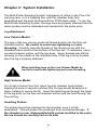
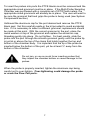
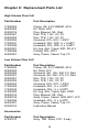
1
Multi-Probe Sampling System User Guide & Manual Rev. 06/05/12 Part #22200012 Table of Contents CHAPTER 1: SYSTEM DESCRIPTION ..................................................................... 2 FUNCTION AND THEORY ................................................................................................ 3 SYSTEM COMPONENTS ................................................................................................... 4 CHAPTER 2: SYSTEM INSTALLATION .................................................................. 6 CHAPTER 3: SYSTEM OPERATION ........................................................................ 8 CHAPTER 4: SYSTEM MAINTENANCE .................................................................. 9 CHAPTER 5: SYSTEM TROUBLESHOOTING ..................................................... 10 CHAPTER 6: SYSTEM SPECIFICATIONS ............................................................. 11 CHAPTER 7: SYSTEM SCHEMATIC ...................................................................... 12 CHAPTER 8: REPLACEMENT PARTS LIST ......................................................... 13 THE WARRANTY ........................................................................................................ 16 EQUIPMENT RETURN POLICY ............................................................................... 16 EQUIPMENT DECONTAMINATION ....................................................................... 16 1 DOCUMENTATION CONVENTIONS This uses the following conventions to present information: WARNING CAUTION NOTE An exclamation point icon indicates a WARNING of a situation or condition that could lead to personal injury or death. You should not proceed until you read and thoroughly understand the WARNING message. A raised hand icon indicates CAUTION information that relates to a situation or condition that could lead to equipment malfunction or damage. You should not proceed until you read and thoroughly understand the CAUTION message. A note icon indicates NOTE information. Notes provide additional or supplementary information about an activity or concept. 2 Chapter 1: System Description Function and Theory The Multi-Probe Sampling System Flow Cell is designed for use in either high volume (1-3 gpm.) or low volume, (100ml to 1 gpm.) applications. Geotech’s flow cell systems are capable of supporting up to five probes simultaneously from a variety of meter and probe combinations. The system includes grommets of varying sizes to accommodate many of the most common sensor probe diameters. Geotech multi-parameter meters are strongly recommended for use with these systems and are available as a complete flow cell and meter kit. Water from the sample or discharge stream of a pumping device is introduced through the bottom of the flow cell chamber. Geotech’s engineered flow pattern is designed in such a manner that water flows in a circular pattern across the analytical probes and discharges through the top of the chamber. The design of the Geotech Multi-Probe Sampling System is such that no manual stirring of the probes or sample is necessary. Additionally, there is minimal contact of the probes with air, thus assuring maximum contact of the sample with the probes for accurate and reliable readings. Geotech Multi-Probe Sampling System Flow cells also feature a blow-out plug to assure the system is not over pressurized. With Geotech’s optional three way valve assembly (sold separately), you can moderate the discharge stream from your pump to properly use your Flow Cell up to its capacity. When its time to collect your analytical sample, the discharge stream can be disconnected from the three way valve, and into your collection container. 3 System Components Hose Barb Fitting Probe Port Chamber Body Top Stainless Steel Clamp Chamber Body Bottom Retaining Pin for legs Blow Out Port Drain Plug Hose Barb Fitting Aluminum Leg Rubber Foot 4 The probe chamber accepts up to five probes simultaneously. Four of the ports accommodate probes from ⅛” to ⅝” in diameter. The fifth port can accommodate from ¾” to 1”. Any or all ports can be plugged off with a PTFE blank when not in use. Each port contains: 1 1 1 1 Silicone grommet Aluminum washer (sized to fit) PTFE blank seal Aluminum threaded cap Each multi-probe monitoring chamber comes with five different sizes of probe grommets and associated parts: 2 2 1 1 1 5 ft .375 to .500 probe gripping range .500 to .625 probe gripping range .750 to .875 probe gripping range ⅜” Hosebarb inlet ½” Hosebarb outlet ½ x ⅝” vinyl tubing Three additional probe grommets & washers are also sent with complete multi-probe monitoring chamber kits. 1 1 1 1 1 1 1 1 .125 to .250 probe gripping range .250 to .375 probe gripping range .875 to 1.00” probe gripping range blow out plug ¼” Hosebarb for inlet ½” Hosebarb for inlet gasket for unit O-ring for legs 5 Chapter 2: System Installation The Multi-Probe Sampling System is shipped out, either in the Flow Cell carrying case, or in a shipping box, with the chamber body fully assembled and the ports blocked with the PTFE blank seals. To use the Multi-Probe Sampling System, the legs must be properly attached and the meter probes must be calibrated and inserted into the probe ports. Leg Attachment Low Volume Model The legs of the low volume model will thread directly into the flow cell chamber bottom. Be careful to avoid over-tightening or cross threading. Carefully align the threads of the aluminum leg with the threaded brass inserts in the bottom of the flow cell. If necessary, use a counterclockwise motion until the leg stops. Some threads may still be showing on the outside of the chamber body. If the leg is firmly in place, then the leg is properly attached. When installing legs on the Low Volume Model be careful to avoid over-tightening and cross threading. High Volume Model For a High Volume Flow Cell, insert leg into chamber body bottom, aligning roll pins on leg with notches (the O-rings should already be in place, helping to secure the fit). Insert the retaining pin through the holes in the leg ports on the flow cell chamber bottom and the hole through the flow cell leg. Inserting Probes The probes should be inserted into the chamber once it is fully assembled. This will protect the probe tips from accidental damage. If the chamber is ever disassembled with probes installed in the ports, the top should be carefully laid on its side. 6 To insert the probes into ports the PTFE blanks must be removed and the appropriate sized grommet must be in place. If the Multi-Probe Sampling Chamber was purchased with a complete set of WTW field meters, the appropriate sized grommets will already be in place. The user will want to be sure the grommet that best grips the probe is being used (see System Components section). Unthread the aluminum cap for the port desired and remove the PTFE blank seal. Set this carefully aside in the kit provided to avoid accidental loss. If it is necessary to select a different grommet; replacement should be made at this point. With the correct grommet in the port, place the metal washer on top of the grommet and replace the aluminum cap, threading gently into place. Do not tighten. For best results, slide the probe into the port through the silicone grommet gently until the probe tip is just at or above the top of the clamp that holds together the top and bottom of the chamber body. It is important that the tip of the probe be inserted below the bottom of the port, yet be at least ½” away from the bottom of the chamber. Do not jam, or use so much force inserting probes that they impact the chamber bottom or cause damage to the probes. When the probe is properly inserted, tighten the aluminum cap being careful not to over-tighten. Over-tightening could damage the probe or crack the Flow Cell ports. 7 Chapter 3: System Operation Once all of the probes have been calibrated and are in place, monitoring can begin. This unit is designed to be used directly in-line from a ground water sampling pump or any other water source that is pumped or can flow up through the chamber. Water is pumped through the bottom of the monitoring chamber. As it fills, water circulates around the probe, and exits through the top of the chamber. As the water flows through the chamber, use the analytical instruments to monitor readings and chart or data-log the results. This is not a pressure chamber. System limitations are a maximum 8 psi differential pressure or the pressure blow out plug will blow out. Removing Probes When removing the probes, turn the aluminum cap counterclockwise until very loose. Firmly grasp the probe where it enters the port and pull straight up. If the probe does not pull out easily, turn aluminum cap until it comes off. Gently wiggle the silicone grommet until it loosens. When the grommet is loose, the probe should be easily pulled from the port. Replace the PTFE blank seal between the grommet and the metal washer when storing. Replace and re-tighten aluminum cap and repeat this procedure on the next probe. 8 Chapter 4: System Maintenance Care of the Multi-Probe Monitoring Chamber Although polycarbonate is a durable plastic, it can be easily scratched. Therefore, reasonable care should be used in handling and cleaning the unit. Abrasive cleaners should not be used. All sediment residues should be removed by immediately flushing and thoroughly rinsing. Organic solvents which attack the plastic should, of course, be avoided. The unit may be fully disassembled for cleaning and decontamination if desired. Because the sample is taken at a point in-line before the flow cell chamber, many users simply rinse the Multi-Probe Sampling system thoroughly with clean water, inside and out to clean. Any detergent solutions will be harmful to polycarbonates. Limit exposure to detergent solutions to under 1 (one) minute. Dilute mineral acids may be used without damage to the unit. With proper treatment, the unit will give long and satisfactory service. Polycarbonate is easily scratched and damaged with improper handling. Do not use abrasive cleansers on flowcell. Immediately remove sediment residues. Avoid contact with organic solvents or detergents. Disassembly of Flow Cell Chamber Body To disassemble, pull stainless clamp latch back until clamp is released. Unhook “T” bolt and remove clamp. For assembly, reverse procedures. When re-assembling flow cell chamber body, be sure to place gasket back between flow cell top and flow cell bottom. The clamp has been factory preset to the right size for the flow cell body and should not be re-adjusted. 9 Chapter 5: System Troubleshooting Problem: Leaking from around the probe Solutions: 1) Check grommet for correct size and make sure the metal washer has been used. Has unit been tightened down properly? Be sure not to over-tighten. 2) Check unit for cracks. If cracks are present and leaking, contact Geotech Environmental Equipment Inc. at 800-833-7958 for a replacement. Problem: Air is trapped in ports Solution: 1) Has air been purged? To purge, loosen cap while pumping sample water through the flow cell and allow air to escape, once done, re-tighten cap. Problem: Blow out plug keeps popping: Solution: 1) Double check your flow rate with the specifications of the Flow Cell. If you are exceeding the Flow Cell flow rate, you could be exceeding the 8 PSI limit for the blow out plug. Reduce your flow rates if possible, or contact Geotech Environmental Equipment Inc. at 800-833-7958 for possible solutions. 10 Chapter 6: System Specifications Dimensions: Inlet Outlet Flowcell leg length Width with clamp Grommets included accommodate the following diameter of probes Grommet also available Parts kit includes grommet sizes Materials: Cell top Cell bottom polycarbonate Cell bottom acrylic O-ring Clamp Grommets Gasket Pressure relief valve Legs Leg end covers 3/8” 1/2” 12” 8” .125 to .250”, .250 to .375”, .375 to 500”, .500” to .675”, .750 to .875” .875 to 1.00” .500” to .675”, .375 to .500”, .875” to 1.00” medical grade polycarbonate (high volume) medical grade (low volume) machined medical grade silicone stainless steel medical grade silicone medical grade silicone medical grade silicone anodized aluminum red neoprene 11 Chapter 7: System Schematic 12 Chapter 8: Replacement Parts List High Volume Flow Cell Part Number Part Description 17500004 52200004 22200015 22200001 22200002 12200003 17200041 17200039 52200007 17500098 52200001 Clamp, SS, 6.75 VBAND, AFH Kit, Parts, HFC Plug, Blowout, SIL, Red, Disc, TFE, 1.00 / .03, FC Disc, TFE, 1.50 / .03, FC Grommet, NTL, 875 / 1.00FC Hosebarb, NYL, 90D, ¼ x ⅜ MPT Hosebarb, NYL, 90D, ½ x ⅜ MPT Kit, Leg, AL6, Tripod, 60D, PK of 3 O-Ring, NTL, #013 Assy, Pressr, Vessel, Top, FC Low Volume Flow Cell Part Number 17500004 52200005 22200006 22200007 22200001 22200002 12200003 17200034 17200035 57500003 22200015 22200016 17200036 52200001 22200012 Part Description Clamp, SS, 6.75 VBAND, AFH Kit, Parts, LFC Grommet, SIL, 125 / 250, FC, Red Grommet, SIL, 250 / 375, FC, Red Disc, TFE, 1.00 / .03, FC Disc, TFE, 1.50 / .03, FC Grommet, NTL, 875 / 1.00FC Hosebarb, NYL, ½ x ½ MPT Hosebarb, NYL, ¼ x ½ MPT Kit, Leg, AL6, Tripod, 3/pk, STRT Plug, Blowout, SIL, Red, Assy, Pressr, Vessel, ACR, BOT, LFC Hosebarb, NYL, ⅜ x ½ MPT Assy, Pressr, Vessel, Top, FC Instruction Manual Accessories Part Number 57500010 Part Description Assy, TEE, Valve, PVC, 3-way 13 Notes 14 Notes 15 The Warranty For a period of one (1) year from date of first sale, product is warranted to be free from defects in materials and workmanship. Geotech agrees to repair or replace, at Geotech’s option, the portion proving defective, or at our option to refund the purchase price thereof. Geotech will have no warranty obligation if the product is subjected to abnormal operating conditions, accident, abuse, misuse, unauthorized modification, alteration, repair, or replacement of wear parts. User assumes all other risk, if any, including the risk of injury, loss, or damage, direct or consequential, arising out of the use, misuse, or inability to use this product. User agrees to use, maintain and install product in accordance with recommendations and instructions. User is responsible for transportation charges connected to the repair or replacement of product under this warranty. Equipment Return Policy A Return Material Authorization number (RMA #) is required prior to return of any equipment to our facilities, please call 800 number for appropriate location. An RMA # will be issued upon receipt of your request to return equipment, which should include reasons for the return. Your return shipment to us must have this RMA # clearly marked on the outside of the package. Proof of date of purchase is required for processing of all warranty requests. This policy applies to both equipment sales and repair orders. FOR A RETURN MATERIAL AUTHORIZATION, PLEASE CALL OUR SERVICE DEPARTMENT AT 1-800-833-7958 OR 1-800-275-5325. Model Number: ________________ Serial Number: ________________ Date: ________________ Equipment Decontamination Prior to return, all equipment must be thoroughly cleaned and decontaminated. Please make note on RMA form, the use of equipment, contaminants equipment was exposed to, and decontamination solutions/methods used. Geotech reserves the right to refuse any equipment not properly decontaminated. Geotech may also choose to decontaminate equipment for a fee, which will be applied to the repair order invoice. 16 Geotech Environmental Equipment, Inc th 2650 East 40 Avenue Denver, Colorado 80205 (303) 320-4764 ● (800) 833-7958 ● FAX (303) 322-7242 email: [email protected] website: www.geotechenv.com