1
1. Introduction
The XPDM is a portable, hand-held, microprocessor controlled, battery operated dewpoint meter with built in dry-storage for the sensor. The instrument is ideally suited for all
applications, where quick and precise measurements are required.
Standard Equipment:
1. XPDM Portable Instrument with
sensor, desiccant cartridge and
lithium battery.
2. 2 VCO to Swagelok fittings and 2
Swagelok to barbed hose fittings.
3. Calibration bulb.
4. Shoulder strap.
8
Optional Equipment:
5. VCO to VCO Fittings.
6. Pig tail.
7. Flexible stainless steel hose.
8. Pressure regulator, all stainless
steel, (preset at 1.5 atm) with
mounting bracket.
9. Coalescing filter, all stainless steel
with mounting bracket.(not shown)
10. Wall transformer (with factory
installed I/O option).
11. Replacement desiccant cartridge.
12. Padded transport case.
6
3
5
7
10
12
2
3
4
1
page 1
2
11
2. Precautions
•
•
•
•
•
•
•
•
•
Warranty limitation: The XPDM’s sample cell/piston assembly should not be disassembled except by factory trained personnel. The warranty is voided, if the sample
cell piston assembly is disassembled by the customer.
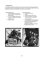
Avoid contaminated sample streams: The XPDM has been designed to allow for fast
and precise measurements of dewpoints as low as -100 °C. Therefore, all surfaces in
contact with the sample stream are made from electropolished stainless steel. This
minimizes the time for the instrument to reach equilibrium with the sample stream,
thus speeding up the measurement. The introduction of corrosive gases or gases
contaminated with oils, solvents etc. may damage or coat the electropolished surfaces and slow down the measurement. Surfaces contaminated with oils etc. can be
cleaned by factory trained personnel (please contact your sales representative). Surfaces damaged by corrosive gases are damaged permanently, causing longer
response times. Gases containing chlorine, ammonia, HCl or SO2 may also cause
damage to the sensor. SO2 can be monitored when the moisture content is low.
Avoid liquid water: Avoid the introduction of liquid water into the sample cell, as this
may damage the sensor. Do not breathe directly into the instruments sample ports,
as condensation may form which could damage the sensor element. If liquid water
can not be avoided, order the XTR-65W sensor which is water proof, but has a limited
range, and a slower dry down response.
Avoid high pressure: The XPDM has been designed for operation at pressures
slightly above atmospheric, however each sample cell/sensor piston/dry-storage
assembly has been tested for pressures up to 120 PSI. Do not introduce sample
streams, which could cause pressure rises above 100 PSI. Make your measurements
at atmospheric pressures, and use the pressure calculation feature to calculate dewpoints at higher pressures. Ask your representative for a regulator installation kit.
Exercise Caution with Hazardous Gases: Please use appropriate precautions if the
sample you are about to measure is hazardous. Place the unit in a safe area, if it is to
be used with hazardous gases. Please be aware that the possibility of a small leak
always exists. Such a leak will not influence the accuracy of the measurement, but
may represent a risk if the sample gas is of hazardous nature.
Avoid Extreme temperatures: Do not install the unit near heat sources such as radiators or air ducts. The instruments’ operating temperature range is -10°C to 50°C.
Avoid Mechanical Vibration: Do not install the unit in places subject to extreme
mechanical vibration or shock. Use resilient mounting, if shock and vibration are not
avoidable. Call your representative if in doubt.
Avoid long exposures of sensor element to room air: For reasons explained later in
this manual (section 7), do not expose the sensor to room air for longer then necessary (1 - 2 Minutes). The sensor is exposed to room air, when the sensor actuator is
in the out position and no sample line is connected, or the sample gas is shut off. It is
best to push the sensor back into dry-storage, after a measurement is completed and
whenever the instrument is not in use.
Do not force the Actuator: Remove any port obstructions (such as shipping caps)
before operating the Actuator.
page 2
3. Principle of Operation
Dewpoint sensors, like all hygroscopic materials, adsorb much faster than they desorb.
Therefore, an accurate measurement will be obtained much faster, if at the beginning of
the measurement, the sensor is at a dewpoint drier than the gas to be measured. The
XPDM design allows the sensor to be moved directly between dry-storage and the sample
cell, without any exposure to ambient air.
Sensor in
dry-storage position
Sensor In
measuring position
9
9
8
5
1
2
2
1
6
6
3
6
4
5
4
11
6
3
11
7
10
10
7
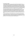
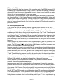
1. Sample Gas In
2. Sample Gas Out
3. Piston
4. Sample Cell
5. Sensor
6. Spring loaded PTFE seals
7. Sensor Actuator
8. Desiccant Chamber
9. Filter Mesh
10.Electronic Board
11.Instrument Case
The drawing on the left shows the XPDM with the sensor in dry-storage position. The sensor is enclosed in a gas-tight container and surrounded by desiccant. The sample gas
passes through the sample chamber and prepares the environment for measurement.
Blocking of the outlet port will pressurize the sample chamber and move the piston into
the position shown on the right. The sensor is now exposed to the sample gas without ever
having been exposed to ambient air. After the measurement is taken, pushing in the sensor actuator will return the sensor into dry-storage, where it will dry down and ready itself
for another fast measurement.
page 3
A note about dry-storage
The dry-storage consist of a stainless steel container filled with desiccant. The electropolished stainless steel sensor guard slides between the dry-storage and the sample
cell through a spring energized PTFE seal, assuring maximum possible gas tightness
and minimum gas transport between the two chambers when the sensor is moved. When
in dry-storage, the sensor guard is separated from the desiccant by a stainless steel wire
mesh with a thickness of 127µ (0.005”) and a mesh size of 100µ. This keeps the distance
between the sensor and the desiccant to a minimum, which is critical for fast and low drydowns, while protecting the sensor from contamination with desiccant particles.
The factory supplied desiccant provides dry-storage dewpoints as low as -80°C when
fresh. When the sensor is pushed into dry-storage it will take some time to dry down
completely and reach equilibrium with the dewpoint in the dry-storage. The dry-down
time to equilibrium depends on how wet the sensor was before it was returned to drystorage, and in case that it was completely wet, how long it had remained in wet condition.
To take full advantage of the dry-storage, make sure, that the dry-storage dewpoint is
below the expected dewpoint of the sample gas by periodically checking the indicated
dewpoint after the sensor has remained in dry-storage for an extended period of time, for
example over night. Replace the desiccant cartridge, if the dry-storage dewpoint is much
higher than -80°C and above your expected sample dewpoints.
page 4
4. Operating the XPDM
4.1. Sample Hook-up
4.1.1. Fittings
The XPDM can be hooked up to the sample gas using a variety of fittings, depending on
the application. The instruments’ sample ports are 1/4” VCO female, to assure proper
seals for even the lowest dewpoint measurements.
Depending on the application and needs, we recommend the use of one of the following
methods of attachment:
• VCO ➜ VCO: This method is ideal for all applications, including the use of flexible
stainless steel hoses, available optionally.
• VCO ➜ Swagelok: This method is suitable for all applications where rigid pipe connections are acceptable.
• VCO ➜ Swagelok ➜ Barbed Hose Fitting: This method is acceptable for dewpoints
above -65°C and should in all cases be used only with PTFE tubing.
4.1.2 Recommended Pipes
Stainless steel pipes should be used exclusively, for dewpoints below -65°C. Your representative has a flexible stainless steel hose available. The length of the sample line to the
instrument should be kept as short as possible, to assure fast equilibrium. We recommend
the attachment of at least 12" long stainless steel pipe at the outlet port to avoid back flow
of ambient air when sampling at low flow rates, ask your representative for the optional
pigtail.
PTFE tubes are perfectly acceptable, and offer advantages due to their flexibility, for dewpoints above -65°C. However, PTFE tubes should be kept as short as possible.
Under no circumstances use rubber or plastic tubes, which are both, hygroscopic and permeable. No valid measurements can be expected when such materials are used.
4.1.3. Sample conditioning
• Pre-filters: Do not use any pre-filters for oil, particles or liquid water when measuring
dewpoints below -65°C. Pre-filters store and release water vapor, and slow down and
distort the measurement at low dewpoints.
• Pressure regulators: Do not use a pressure regulator containing any materials other
than stainless steel, for dewpoints below -65°C. To ensure the use of the right product, use regulators provided by your sales representative.
4.2. Measuring
• Turn the unit on by pushing the Power button.
• Select the desired engineering units, using the up or down buttons.
• Take note of the indicated dewpoint while the sensor is still in dry-storage.
• Introduce the sample gas into the unit while the output port is unobstructed. Wait one
minute, for every 10°C below 0°C of expected dewpoint, to allow the sample chamber
to adapt to the sample dewpoint.
• Block the outlet port. The small pressure build-up in the sample chamber should be
sufficient to push out the piston and move the sensor into the sample chamber. If not
sufficient, assist by gently pulling on the sensor actuator located on the front of the
page 5
•
instrument, while still blocking the sample outlet port.
Observe the change in dewpoint indication. The reading will be stable within about 3
minutes, if the dewpoint is increasing. A longer stabilization period will be required, if
the dewpoint is decreasing. Make sure the reading has completely stabilized before
taking the final reading. After the reading is taken, push the sensor actuator back into
the dry-down position.
Note that when the instrument is being operated on a battery it will shut off automatically
if no buttons are pressed for: 6 minutes when sensor is in the sample chamber (the out
position), or 3 minutes when sensor is in the desiccant.
page 6
5.0 The User Interface
The user interface consists of a custom LCD display, an audio indicator, 5 push buttons
and a sensor actuator.
5.1 Display Conventions
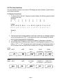
1. To display letters with the 7 segment numeric display, the following pseudo-alphanumerics are used:
Numbers:
0
1
2
3
4
5
6
7
8
9
Letters:
A B C D E F G H I
$ % & ' ( ) * + ,
Symbols:
?
"
J L N O P Q R S T U X Y Z
- / 1 2 3 4 5 6 7 8 ; < =
.
2. The instrument will indicate whether a particular mode lets you change a parameter by showing the word “SET” in the upper left corner of the display. Be careful
not to change any parameter inadvertently.
3. °C°F appear simultaneously, to indicate the sensors’ attenuation in decibels.
4. Values higher than ±1999 and lower than ±0.01 are displayed in powers of 10±3.
Either a “10 3” or “10-3” will appear above and to the right of the displayed value, if
this is required, and the value will be rounded off to 3½ digits. Examples follow:
actual
value +20°C
+68°F
23612
1104.2
17.688
ppmV
lbs H20/mmSCF
grams H20/meters3
x10 3
PPM
˚C
DEWPOINT
˚F
actual
value -100°C
DEWPOINT
DEWPOINT
DEWPOINT
-148°F
DEWPOINT
DEWPOINT
G/M3
0.013849
0.00092115
0.00001475
ppmV
lbs H20/mmSCF
grams H20/meters3
x10 -3
PPM
˚C
LBS
x10 -3
x10 -3
˚F
DEWPOINT
DEWPOINT
page 7
DEWPOINT
LBS
DEWPOINT
G/M3
5.2 Operating State
Refer to Appendix A for a flow diagram of the operating state. The XPDM is powered ON
by pressing the ‘Power’ button until a beep is heard; to activate the backlight, continue to
depress the ‘Power’ button until the backlight turns on. Keep in mind that with the backlight on the unit consumes about 5 times more power.
Upon power up the unit performs certain initialization tests (see section 9), and enters
the ‘Operating State’, in the Viewing Dewpoint mode. Depressing the ‘Mode’ button will
change modes in the following order: Viewing Dewpoint ➜ Viewing Sensor Temperature
➜ Start Autocal ➜ Viewing Serial Number ➜ (back to) Viewing Dewpoint. The unit will
return to Viewing Dewpoint mode if no buttons are pressed for 30 seconds, unless it is
performing Autocal.
5.2.1 Viewing Dewpoint Mode
In this mode the user can view the dewpoint, signified by the presence of the ‘DEWPOINT’ legend on the lower left of the display. The available engineering units in which to
view the moisture content are °C, °F, PPM, LBS and G/M3; the up and down buttons
scroll back and forth through these units in respective order. The °C and °F are dewpoint
readings. The ppm is parts per million by volume computed at the sensor pressure (more
about pressure later). The Lbs and G/M3 are pounds of water per million standard cubic
feet and grams of water per standard cubic meters, both in Natural Gas, they are computed according to data derived by IGT Research Bulletin 8, taking into account sensor
pressure.
A short press of the ‘pressure correct’ button toggles the unit in and out of pressure correct mode. When there is no pressure correction applied the PSI legend does not
appear. The PSI legend flashes at the bottom of the display, when there is pressure correction in the computation of the displayed values.
Pressure correction is used in the context that the values displayed signify the moisture
content at some pressure (we refer to this as the ‘Gas Pressure’) different than the pressure at the sensor. Note that PPM, LBS and G/M3 readings are by definition unaffected
by pressure correction because only the pressure at the sensor affects their value. While
°C and °F are affected by pressure correction by reporting what the dewpoint would be at
the Gas Pressure when the dewpoint is what is measured at the pressure at the sensor.
However, this also implies that whether pressure correction is applied or not the PPM,
LBS and G/M3 readings are affected by the setting of the sensor pressure.
Sensor pressure is used in the context that this is the pressure inside the sampling
chamber when performing the measurement.
Gas pressure is used in the context that this is the pressure to be used in computing
what the dewpoint would be at a pressure different than the one in the sampling chamber.
A long press of the Pressure Correct button, while in the pressure correct mode (flashing
PSI legend), changes the unit to the View/Set Sensor Pressure sub-state. The display
has the ‘SET’ and ‘PSI’ legends on and alternately shows 6(1and the currently set value
for the sensor pressure. The up and down buttons allow the user to modify the sensor
pressure, while a short press of the pressure correct button toggles the Sensor Pressure
setting between whatever value is on the display and 14.7 psi ---- this is a quick way to go
page 8
back to atmospheric settings. A long press of the pressure correct button changes the
unit back to the Viewing Dewpoint Mode. Pressing the ‘Mode’ button changes the unit to
the View/Set Gas Pressure sub-state. The display has the ‘SET’ and ‘PSI’ legends on
and alternately shows *$6and the currently set value for the gas pressure. The up, down
and pressure correct buttons operate in the same manner as in the Sensor Pressure
sub-state. Pressing the ‘Mode’ button changes the unit back to View/Set Sensor Pressure sub-state, and so forth.
The factory default settings are: 14.7psi for both sensor and gas pressure and pressure
correction disabled.
When Pressure correction is disabled all dewpoints are computed by assuming that both
Sensor and Gas Pressures are 14.7psi.
5.2.2 Viewing Temperature at Sensor
In this mode the user can view the temperature at the sensor inside the sampling chamber, signified by the flashing ‘TEMP’ legend on the lower left of the display. The available
units in which to view the temperature are °C and °F. The up and down buttons switch
back and forth between these units.
Pressing the ‘Mode’ button changes to the Start Autocal Mode.
5.2.3 Start Autocal Mode
In this mode the user is prompted to confirm that Autocal should be initiated. This mode
can be skipped by pressing the ‘Mode’ button to go to the View Serial Number Mode or
by cancelling with the down or pressure correct buttons which displays the word &$1 for
1/2 second and goes back to the Viewing Dewpoint Mode.
Autocal can be initiated by pressing the ‘up’ button. The unit will check if the sensor is in
the sampling chamber, if not it will prompt the user to pull the sensor out of the desiccant
by beeping and displaying alternately 38/ and 287. Pull the sensor actuator out, when
this message appears.
Since Autocal is a irreversible recalibration of the instrument there is one more beeping
and visual prompting with alternating &1) and$&". The down and pressure correct buttons allow cancelling the Autocal, while the up button confirms it. The unit starts taking
measurements for 1 minute while displaying alternately flashing $&. During this time the
user should occasionally pump saturated air using the calibration bulb into the sample
chamber (see Autocal Instructions). An alternating 6(1 and /2 after one minute,
accompanied by a beeping, indicates the sensor has a reading too low to be from a saturated sensor. This error will cause Autocal to be cancelled. However, if the sensor reading is within range of a saturated sensor, a new calibration is calculated (some numbers
flash on the display),(1'is displayed for 1 second, and the new calibration values are
saved in EEPROM.
5.2.4 Viewing Serial Number Mode
In this mode the user can view the serial number of the sensor. The display shows the
serial number by alternately displaying ;61 and the number. If the number is larger than
1999 then it is displayed in 2 segments, first segment is the thousands signified by the
x103 legend in the upper right corner of the display and the second segment is the units.
page 9
For example serial number 12345 will be shown as:
3
;61
x10
Pressing the ‘Mode’ button changes the unit to the Viewing Dewpoint Mode.
5.3 Set-up State
To enter the Setup State powerup the unit while depressing the Mode key.
Refer to Appendix B for a flow diagram of the Set-up State.
The set-up state provides the following nine capabilities:
1. Testing the optional analog output: By pushing the up, down or pressure correct
buttons, the user forces the analog output to its low, high and mid values, respectively. This facilitates the hook-up and testing of the remote terminal.
2. Display of alternate units: In this mode, a second unit can be chosen to be displayed alternating with the unit selected in the operating state, for example, a dewpoint can be displayed alternating with the sample temperature, or dewpoint can
be alternated in two different units.
3. Selecting the sensor type: In this mode the user can select the software matching
the type of sensor installed in the instrument; XTR-100 (-100°C to +20°C); XTR65 (-65°C to +20°C).
4. Adjusting low end sensor attenuation and/or dewpoint: These modes are used to
enter a data pair representing a low dewpoint and the sensor attenuation measured at this low dewpoint.
3) and 4) are set at the factory and need only be modified when a sensor is changed.
5. Manual calibration: (Not yet available) In this mode, the user can enter multi-point
calibration data to improve the instruments accuracy.
6. Output range setting: These modes are used to set dewpoints corresponding to
the low and/or high end of the current loop output.
7. Lock/Unlock the instrument: This mode is used to block access to parameter settings, protecting the instrument from unauthorized or inadvertent changes of
parameters. Attempting to change settings while instrument is locked will display
/2&and beep
page 10
6. Options
The instrument can be optionally equipped with an output/power supply board, to allow
for the following capabilities:
1. RS-232C.
2. Current Loop output (4-20mA or 0-24mA).
3. Operation from an external power supply e.g. a wall transformer.
6.1 RS-232C
The RS-232C output is provided on a 9 pin sub “D” female connector, located at the rear
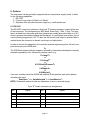
of the instrument. The configuration is 9600 baud, Even Parity, 7 Bits, 1 Stop. The interface is isolated from the sensor and case (however as a sefety precoution there is a 1MΩ
shunt to prevent electrostatic buildup and discharge), it is configured as a modem, thus it
can be directly plugged into a PC. To also use the current loop output, a special cable is
needed since the connector is shared, see the pin out table below.
In order to receive the dewpoint in the currently selected engineering units, the host computer must query the XPDM with:
?CR
The XPDM will respond with the dewpoint, followed by characters indicating the currently
selected engineering units, followed by carriage return e.g.:
C
-79.1degC R
or
C
-110.4degF R
or
0.0339LbsH2O/mmscfCR
or
0.625ppmVCR
or
0.00544g/m3CR
If an error condition exists the XPDM will respond to the question mark with a phrase
describing the error:
C
C
C
SensOpen R or SensSaturated R or SensShorted R
NOTE: Characters marked in bold are indications of sent or received strings.
9 pin “D” female connector pin assignments
pin
Signal
pin
Signal
1
Current Loop out
6
strapped to 4
2
Tx
7
looped from pin 8 through RS-232 level driver
3
Rx
8
looped to pin 7 through RS-232 level receiver.
4
strapped to 6
9
current loop select:Open=0-24mA,Grounded=4-20mA
5
Gnd-RS232 & Current Loop
page 11
If the current loop is not being used, it is safe to connect the DB9 connector directly to a
PC; pins 1&9 will not be dammaged or couse dammage.
The RS-232 levels are generated by the instrument only when an RS-232 level is
detected at the DB9 input. Therefore, when operating from a battery to conserve its
power, disconnect the RS-232 cable unless necessary for the operation.
6.2 Current Loop Output
The current loop signal is provided on the 9 pin sub ‘D’ female connector located at the
rear of the instrument. The current loop output functions only when the instrument is
operated from an external power supply. Pin 1 is the positive current loop output while pin
5 is the ground.
This output is isolated from the sensor and case, however as a sefety precoution, there is
a 1MΩ shunt to prevent electrostatic buildup and discharge.
Note that this connector is shared with the RS-232C interface, see section 6.1 for full pin
assignments. Pin 9 controls the range of the current loop, when grounded the output is 420mA, when left open the output is 0-24mA. The current loop is capable of driving loads
from 0Ω to 500Ω. The output is linearly proportional to the selected engineering units.
The output may be scaled such that it spans only a portion of the full range of the sensor,
this feature may be useful in cases where a higher resolution output is required over a
narrow dewpoint range, or vise versa. To verify or change the current loop scaling follow
the instructions in the set-up mode section 5.3.
The current output is computed by the microprocessor as follows:
If pin 9 is grounded for a 4-20mA range:
(R – L)
O = ------------------ × 16 + 4
(H – L)
Where:
O=output current in mA.
R= value of Reading shown on display in selected engineering units.
L= value of Low Limit of Output Scaling converted to selected engineering units.
H= value of High Limit of Output Scaling converted to selected engineering units.
See section 5.3 to select values for L & H. Their factory defaults are the upper and lower
range of the sensor e.i. for XTR-100 L= -100°C and H= +20°C. The values for L & H are
set up always in °C, however the microprocessor converts them to the currently selected
units. Note that because R, L and H are all in the same units the output current is linearly
proportional to those units. The current is linearly proportional to dewpoint, if the selected
units are °C or °F, however if the selected units are Lbs, ppm or G/M3 then the current is
approximately logarithmically proportional to dewpoint see Appendix C.
After hooking up the current loop output, it can be forced to its low, mid and high points
by following the instructions in section 5.3. This procedure may be helpful in testing the
connection and setting-up the termination equipment.
page 12
6.3 Operating from an external Power Supply
The external power connector is a 2mm power jack located on the rear of the unit. This
input can accept either AC or DC power and is thus polarity independent.
The unit requires 13VDC to 25VDC, when operating from external DC power.
The unit requires 12VACrms to 25VACrms, when operating from external AC power.
In either case the unit can draw up to 50mA when the backlight is on and supplying current loop output. The power input is protected with a 250mA fuse.
The power input is isolated from the sensor and case, however as a sefety precoution,
there is a 1MΩ shunt to prevent electrostatic buildup and discharge.
page 13
7. Automatic Calibration
The instrument is calibrated at the factory with the shipped sensor, and does not need to
be re-calibrated prior to use. Do not re-calibrate the unit unless you suspect a problem.
The XPDM instrument takes advantage of the pre-designed saturation point of Xentaur
HTF sensors. Because Xentaur HTF sensors saturate at a factory designed dewpoint
above +20°C, they can be calibrated by simply exposing them to a micro-climate with any
dewpoint above +20°C and adjusting the calibration equation.
Remember that the micro-climate does not have to be accurate, it just has to be higher
than the pre-designed saturation level.
The automatic calibration procedure is as follows:
1. Make sure that the ambient temperature where you are performing the autocal is
above +20°C. Check the temperature of the unit using its built in temperature indication.
2. Remove the adapter from the bulb (hand pump).
3. Moisten the sponge with 1 or 2 drops of water and replace the adapter back on
the mouth of the bulb.
4. Turn instrument on. Refer to section 5.2.
5. Press the Mode key twice. The display will indicate &$/
6. Press the Up key, to confirm you want to perform a calibration.
7. Pull sensor actuator to measurement position, and pump into one of the input
ports.
8. Push Up key to initiate the calibration procedure.
9. Keep pumping intermittently to assure wet micro climate in sample cell, while the
display is flashing $&B$&.
10. After one minute, the instrument displays calibration numbers to be stored in the
instruments memory, displays (1' and thereafter goes back into measuring
mode. The instrument is now calibrated.
11. Push in the sensor actuator.
Instrument calibration is recommended in 12 month intervals, the XTR65 sensor
should be recalibrated after prolonged exposure to liquid water. Make sure the sensor
has been sufficiently dried down and, simply follow steps 1 - 11 of the above procedure.
It is recommended to keep the sensor exposure to room air as short as possible to
avoid super saturation of the sensor. While super saturation is not damaging to the sensor, it will prolong the initial dry-down time after it is exposed to a dry environment. Therefore, move the sensor out of the dry-storage only after you are ready to proceed with the
calibration procedure and push the sensor in dry-storage immediately after the calibration procedure is completed. Under certain conditions, an over (super) saturated sensor
may need to be completely dried out before either auto calibration or manual calibration
is performed. Symptoms of these conditions are a sensor that will not go through the
automatic calibration function to the (1'display, or a sensor that will not dry down after
calibration. To dry, install sensor in either a known dry gas stream i.e. instrument quality
air or dry nitrogen, or push the sensor back into the dry-storage. After a minimum dry out
period of 24 hours, proceed with the calibration procedure.
page 14
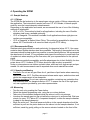
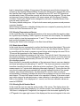
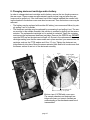
8. Changing desiccant cartridge and/or battery.
In order to change desiccant cartridge and/or battery, remove the two thumb screws on
the rear cover. These screws are approximately seven inches long and after they are
loose must be pulled out. If the instrument has a filter bracket installed the screws holding the bracket to the bottom cover must also be removed. Then the bottom cover may be
removed.
• The battery may be replaced with another 9V battery (we recommend lithium) by simply pulling it out of its holder.
• The desiccant cartridge may be replaced by unscrewing it and pulling it out. The sensor must be in the sample chamber, this position is reached by pulling out the sensor
actuator. The replacement cartridge is in a sealed tin container. Open the container
and remove the replacement desiccant cartridge. Remove the GREEN cap, DO NOT
open the RED cap as the desiccant will spill out. Screw in the replacement desiccant
cartridge making sure that the same seals are in place as when you removed the old
cartridge, such as the PTFE washer and Viton ‘O’ ring. Tighten the desiccant cartridge securely into place. Move the sensor actuator back and forth to make sure that
the sensor moves in and out of the desiccant smoothly.
Sensor
Sample
chamber
Spring energized
PTFE “O” ring
PTFE washers
Viton
“O” ring
Desiccant
cartridge
100µ SS wiremesh filter
Bottom of VCO fitting, “O” ring visible
Bottom view of XPDM with cover open.
The sample chamber and desiccant cartridge are shown cut open to facilitate an
understanding of the mechanism and how it
is assembled.
page 15
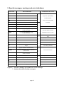
9. Special messages, warnings and error indications
(55
&6)
(55$'
(555()
/2%$7
LO 51*
TEMP
HI 51*
TEMP
231
6$7
6+5
Unidentified power-up failure.
A/D converter failure.
for service.
Reference voltage for A/D out of spec.
Low battery voltage.
Instrument low temperature range
has been exceeded.
Instrument high temperature range
has been exceeded.
Sensor circuit is open.
Sensor is saturated.
Sensor circuit is shor ted.
'5<
Viewing dewpoint while sensor is in desiccant drystorage.
38/287
6(1/2
(55((3
/2&
,1287
;(1
%<(
if problem persists,
return to your representative
Trying to calculate dewpoint for undefined sensor.
cycle power / replace battery,
EEPROM Check Sum Failed.
'%
power on tests
%
RAM write/read test failed.
Trying to calibrate an undefined sensor.
Prompting to pull out the sensor from desiccant to
perform autocal.
Sensor reading is ‘too’ low to be from a saturated
sensor, for autocal.
system tests once per 2 min.
(55
PROM check sum failed.
dewpoint displays tests
HI
REQUIRED ACTION
EEPROM write cycle not completed.
Attempting to modify a locked unit.
Sensor is neither in nor out of desiccant.
Turn on message, Xentaur (Greek ;=X)
replace battery.
make sure that the unit is at a
temperature of -10°C to +50°C.
check sensor. wetup sensor to see if it will
react
dry down the sensor.
check sensor.
select sensor and autocal.
a reminder that the dewpoint in the desiccant is being measured.
autocal tests
(55
LO
EXPLANATION
see autocal instructions.
if this persists, return for service.
miscellaneous
DISPLAY
unlock unit, see set-up mode.
pull out or push in the sensor actuator
Turn off message, good-bye.
Legend: denotes a beeping accompaniment to the message.
denotes alternately flashing messages.
page 16
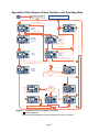
Appendix A: Flow diagram of User Interface in the Operating State
For backlight, hold
until it comes on
Flashing PSI means
pressure corrected dewpoint
Toggle Pressure Correct
Display
˚F
1/2 sec
Viewing
Dewpoint
PSI
{
¡DEWPOINT
30 seconds anywhere (other than
"Autocal") without key press
Power ON initialization
and sign on message
SHORT PRESS
units
LONG PRESS
AND PSI MODE
Toggle 14.7 psi
SET
Viewing
Temperature
at Sensor
˚C
View/Set
Sensor
Pressure
VALUE
PSI
{
{
¡TEMP
SHORT PRESS
values
units
LONG PRESS
Toggle 14.7 psi
SET
SET
Start
Autocal
View/Set
Gas
Pressure
VALUE
{
{
PSI
SHORT PRESS
values
LONG PRESS
Confirm autocal
SET
NUMBERS
CALCULATING
CALIBRATION
SET
Confirm
autocal
1 minute
SET
{
1 sec
SET
Sensor
Reading
OK
TOO LOW
SET
{
IN
DESICCANT
New calibration values are saved
Legend: / separates alternatively displayed messages
denotes beeping
Buttons without designator or arrow leading out, perform no function
page 17
Cancel Autocal (it is not performed)
few sec
Sensor
Position
OUT
{
Viewing
Serialnumber
Appendix B: Flow Diagram of User Interface in the Set-Up State
For backlight, hold
until it comes on
&
Power ON initialization
and sign on message
Test Analog Output by forcing it to high and low end or midpoint.
Hi/Lo
(E. G. if DB9 connector pin 9 is grounded, Hi =20mA, Lo=4mA, Mid=12mA)
Hi Lo Mid
Choose alternate units to show when displaying dewpoint.
SET
blank
˚F
˚C
ppm
LBS
G/m3
PSI
%
˚C˚F
Temp˚F
Temp˚C
{
Factory default is blank, (there is no alternate display).
Choose sensor type
SET
XTR-65
measure
attenuation of
sensor
{
XTR-100
sensor type
SET
Set measured attenuation at a known low dewpoint
{
Lo
changes by 0.01 db
SET
Set low dewpoint for above attenuation
{
˚C
These are set properly at factory
with shipped sensor.
Do not modify these settings,
unless you are changing the sensor.
units
changes by 0.1˚C
SET
Manual calibration
SET
Lo
value ˚C
Set dewpoint corresponding to low end of analog output
{
Factory default is low range of sensor, e. g. -100˚C for XTR-100
changes by 0.1˚C
SET
Hi
value ˚C
Set dewpoint corresponding to high end of analog output
{
Factory default is high range of sensor, e. g. +20˚C for XTR-100
changes by 0.1˚C
SET
Lock or unlock the unit.
When locked, unit parameters can not be changed
Factory default is locked
Un- Loc
Loc
Legend: / separates alternatively displayed messages
Buttons without designator or arrow leading out, perform no function
page 18
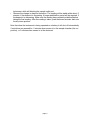
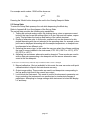
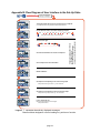
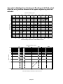
Appendix C: Relationship of Instrument Reading and 4-20mA output
when lbs of H20/million standard cft or ppmv engineering units are
selected.
Instrument reading in ppmV
0
2000
4000
6000
8000
10000
12000
14000
16000
18000
20000
22000
20
19
18
XTR100
17
16
15
4/20 mA output
14
13
12
11
10
9
8
7
6
5
4
0
100
200
300
400
500
600
700
800
900
1000
1100
Instrument reading in LBS of H2O / million standard cubic feet
Instrument reading in ppmV
4.5mA
289.1 LBS = 0˚C = 6063.8 ppmV
5mA
10000
49.3 LBS = -20˚C = 1019.3 ppmV
4/20 mA output
8mA
1000
1.97 LBS = -50˚C = 38.83 ppmV
12mA
100
0.56 LBS = -60˚C = 10.66 ppmV
20mA
10
0
10
R
XT
4.1mA
0.1
1
10
100
Instrument reading in LBS of H2O / million cubic feet
page 19
1000
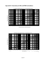
Appendix D: Uncertainty in LBS and PPMV calculations
Uncertainty of LBS-H2O calculation due to +/-3˚C measurment accuracy
-20
-25
-30
-35
Measured Dewpoint ˚C
-40
-45
-50
-55
-60
3˚C
nt -
oi
wp
-65
De
-70
˚C
t +3
oin
p
ew
D
-75
30
20
7
8
9
10
6
4
5
3
2
0.7
0.8
0.9
1
0.6
0.4
0.5
0.3
0.2
0.07
0.08
0.09
0.1
0.06
0.04
0.05
0.02
0.03
-80
Calculated LBS-H2O in Natural Gas @ STP
Uncertainty of ppmV calculation due to +/-3˚C measurment accuracy
-20
-25
-30
Measured Dewpoint ˚C
-35
-40
-45
-50
-55
-60
3˚C
nt -
oi
ewp
-65
D
-70
3˚C
nt +
oi
ewp
D
-75
-80
9
8
7
6
5
4
3
2
1
1000
900
800
700
600
500
400
300
200
100
90
80
70
60
page 20
50
40
30
20
10
0.9
0.8
0.7
0.6
0.5
Calculated ppmV
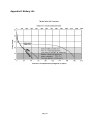
Appendix E: Battery Life
page 21