1
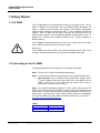
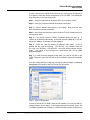
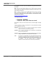
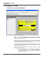
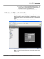
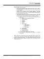
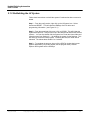
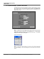
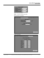
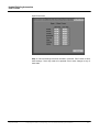
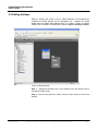
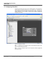
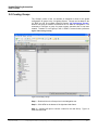
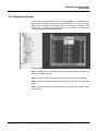
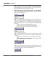
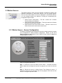
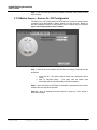
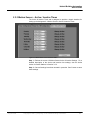
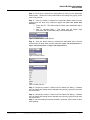
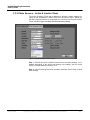
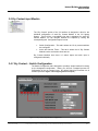
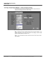
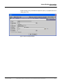
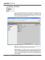
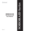
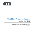
Hubbell LX JENEsys User’s Guide August 2008 Rev. 5 – First Edition Copyright © 2007, Lynxspring, Inc.& Hubbell Building Automation Hubbell Building Automation User’s Guide Trademarks Lynxspring and the Lynxspring logo are U.S. trademarks of Lynxspring, Inc. Other brands and product names mentioned in this manual may be trademarks or registered trademarks of their respective companies and are hereby acknowledged. Copyright Notice Copyright © 2007, Lynxspring, Inc. All rights reserved. This document contains proprietary information which is protected by copyright. No part of this document may be copied, photocopied, reproduced, translated, or converted to any electronic or machine-readable form in whole or in part without prior written approval of Lynxspring, Inc. JENEsys™ is a registered trademark of Lynxspring, Inc. All JENEsys™ logos are property of Lynxspring, Inc. Disclaimer NO WARRANTY. This technical documentation is being delivered to you AS-IS, and Lynxspring makes no warranty as to its accuracy or use. Any use of the technical documentation or the information contained therein is at the risk of the user. Documentation may include technical or other inaccuracies or typographical errors. Lynxspring reserves the right to make changes in this document without prior notice, and the reader should in all cases consult Lynxspring to determine whether any such changes have been made. The information in this publication does not represent a commitment on the part of Lynxspring. Lynxspring shall not be liable for incidental or consequential damages resulting from the furnishing, performance, or use of this material. This guide contains links and references to third-party websites that are not under the control of Lynxspring, and Lynxspring is not responsible for the content of any reference material or linked websites. If you access a third party website mentioned in this guide, then you do so at your own risk. Lynxspring provides these links only as a convenience, and the inclusion of the link does not imply that Lynxspring endorses or accepts any responsibility for the content on those third-party sites. (Revision 5 – First Edition: August 2008) Hubbell Building Automation 9601 Dessau Rd Building One Austin, TX 78754 http://www.hubbell-automation.com Lynxspring, Inc. 8900 State Line Road Suite 220 Leawood, KS 66206 http://www.lynxspring.com August 2008 Copyright © 2007, Lynxspring, Inc. & Hubbell Building Automation 2 Hubbell Building Automation User’s Guide The user manual has the following contents: Section 1 Discusses getting started with the JENE Section 2 Discusses using the JENE on a LX System and base configuration Section 3 Details configuration of System Inputs such as Switch Stations, Motion Sensors, Photo Sensors, and Dry Contacts Section 4 Details configuration of Relay Panels Section 5 Details the extra configuration screens associated with the LX JENE configuration Section 6 Integration information August 2008 Copyright © 2007, Lynxspring, Inc & Hubbell Building Automation. 3 Hubbell Building Automation User’s Guide 1 Getting Started 1.1 LX JENE The LX JENE platform is developed around a protocol extraction model. The LX JENE is designed to communicate with the Hubbell Building Automation LX Series of Lighting control products and provide a user friendly configuration interface and the ability to communicate with 3rd party LonWorks and BACnet systems. Each LX JENE has the ability to discover all LX devices on the LX network and will create a set of configuration graphics for each device found. In addition the LX JENE has the ability to reside on any 3rd party LonWorks or BACnet network. The LX JENE is designed with an ease of use in mind. With the push of a button the LX JENE discovers all LX devices on the network. Please note! The LX JENE must not be used for any other purpose than that for which it was designed. Authorized personnel only may perform installation and repair. 1.2 Connecting to the LX JENE The following steps should be taken prior to connecting to the JENE: Step 1 - Ensure the LX JENE is mounted and powered up. Step 2 – Verify that all LX Devices are connected to the LX JENE’s LON Port #1. Note Important: If the LX JENE has been specified to integrate with a 3rd party LonWorks system then there will be two LON cards on the LX JENE. LON Port #1 is the front LON port while LON Port #2 is accessible on the back of the LX JENE. Step 3 – It is required that laptop computer or a PC is used to connect to the LX JENE. This will require that the connecting computer have the capability to run a web browser. It is also required that the computer employee’s a Java Runtime Environment. If you don’t have a JRE, install the JRE included on the installation CD or go the following link and selection the option that best fits your computer : http://java.com/en/download/manual.jsp Table 1 IP Address Subnet Mask Default Gateway August 2008 192.168.1.120 255.255.255.0 192.168.1.1 Copyright © 2007, Lynxspring, Inc. & Hubbell Building Automation 4 Hubbell Building Automation User’s Guide In order to access the LX JENE for the first time you must set your IP Address on your laptop to match the network configuration of the LX JENE. The subsequent steps will guide you through this process: Step 1 – Push the start button in the bottom left of your computer screen. Step 2 – View your computers Network and Dialup Connections. Step 3 – View the Network Connections on your laptop. Right click your local area connections and select properties. Step 4 – Scroll down and select the Internet Protocol (TCP/IP) selection and click the properties button. Step 5 – The Internet Protocol (TCP/IP) Properties window will pop up. If “Obtain an IP address automatically” is selected proceed to Step 6. If “Use the following IP address” is selected, proceed to Step 7. Step 6 – Select the “Use the following IP address” radio button. In the IP address text box, type the following – 192.168.1.99. In the Subnet mask text box, type in the following – 255.255.255.0. Leave the default gateway text box empty. Your laptop is now configured to communicate with the LX JENE integration platform. Step 7 – In order for these changes to take effect, you need to click OK on the TCP/IP Properties menu and then OK on the Local Area Connections Properties menu. If you are having problems configuring your laptop, reference Figure 1.1 Laptop IP Configuration for a detail on what your screen should look like. Figure 1 – Laptop IP Configuration In order to access the LX JENE’s internal user interface, you must first start up Internet Explorer on your laptop. Once Internet Explorer has started, type in the LX JENE’s IP address (for example a LX JENE with serial number 8418 will have August 2008 Copyright © 2007, Lynxspring, Inc & Hubbell Building Automation. 5 Hubbell Building Automation User’s Guide an IP address is 192.168.1.128) in the address bar, then press the Enter key on your laptop. Note: Once you have finished working on the LX JENE, reset your computer back to Obtain an IP address automatically by selecting the radio button for this option and then clicking OK. Note : If unable to connect to the LX JENE please ensure that your computer has a Java Runtime Environment (JRE) installed. If unsure install the JRE included on the installation CD or go the following link and selection the option that best fits your computer : http://java.com/en/download/manual.jsp The configuration login is: Username: siteadmin Password: 0000 (Note: these are zeros) For a detail of what your screen should look like, reference Figure 1.2 Login Screen. There are 4 primary user types. See Section 5.1 for more information on setting up and managing user accounts. hbaadmin: login has full access to all system functionality used for technical support and advanced commissioning settings. sysadmin: short for system administrator, this is typically the commissioning agent or HBA representative. siteadmin: short for site admistrator, this would normally be the local facilities manager responsible for overall operation of the system. user: August 2008 The system or site admistrator can setup password protected user accounts for employess to have limited access to the system. This user level has predefined access to only the programming section of the JENEsys. This level excludes access to configuration, integration, and other areas that are setup during commissioning. Copyright © 2007, Lynxspring, Inc. & Hubbell Building Automation 6 Hubbell Building Automation User’s Guide Figure 1.2 Login Screen Figure 1.2.1 Security Permssion Upon loggin in, the JENE will begin to upload the JAVA Application to your laptop. You will see a progress indicator and be asked to verify permission to execute this process. Click on the YES button to start. August 2008 Copyright © 2007, Lynxspring, Inc & Hubbell Building Automation. 7 Hubbell Building Automation User’s Guide 2 Launching the LX JENE 2.1 Main Screen Layout and Navigation Figure 2.1 Main Navigation Screen Figure 2.1 shows the main JENE Navigation screen within the Internet Explorer window. This screen will vary depending on the login permission of each user type (sysadmin, siteadmin, user, etc). The top horizontal bar starting with the word “Menu” is not used in the JENEsys programming or configuration. Although some of the buttons are active, they are reserved for troubleshooting with HBA Tech support only. The next dark grey horizontal bar (starting with the orange fox icon) is an alternative navigation aid with drop down menus and also illustrates your current view/position in the navigation tree. The large grey vertical frame on the left is the primary navigation tree. Within that tree there are three sections. a. The home icon (called Home or Hubbell appliance depending on the user permission) has the basic user password administration, the integration settings and the standard LX system level programming submenus. August 2008 Copyright © 2007, Lynxspring, Inc. & Hubbell Building Automation 8 Hubbell Building Automation User’s Guide b. The Config file contains administrative level controls for user accounts, web and TCP/IP settings, system variables as well as a more detailed LX system- level programming tree. c. A files folder that contains logging and system backup files. 2.1.1 Building the LX System For the First Time Building the LX system in a LX JENE is a simple process. The initial use of the interface is to configure the LX Lighting Control System, while the second is to provide a means to configure the integration. The configuration of the LX Lighting System using the LX JENE is discussed throughout the remainder of this section. Step 1 – Ensure all LX devices are connected to the LX LON trunk. Figure 2.1.1a Step 2 of the System build process. Step 2 – To continue to the Build System menu, press the “Skip this step” button. (Figure 2.1.1a) August 2008 Copyright © 2007, Lynxspring, Inc & Hubbell Building Automation. 9 Hubbell Building Automation User’s Guide Note: Under the Config file, double click on the LX System Icon. This will bring up the Local Device Settings Menu. The setting here will generally not be changed, but are easily edited and saved from this window. If changes are made to these settings, the SAVE and the Reboot buttons must be pressed for them to take effect. Note: Always make note of TCP/IP settings, as they are required to log back in after rebooting. Figure 2.1.1b Step 3 of the System build process. Step 3 – Press the “Build System” button. (Figure 2.1.1b) NOTE: The LX panel holds empty slots for 99 Groups, Presets, Schedules and Holidays. There are three options in the System Discovery process for importing programming from the panel to the JENE. “Discover Defined” results in a faster discovery and only imports each program type until an undefined program is encountered. This is the recommended option for new systems and for systems with known programming. “Discover All99” options will import all 99 of each. This is usually only used for troubleshooting. Finally, “Discover None” can be used to only discover system hardware, omitting any programming. August 2008 Copyright © 2007, Lynxspring, Inc. & Hubbell Building Automation 10 Hubbell Building Automation User’s Guide Once the “Build System” button has been pressed a chain of events are fired off in the LX JENE, they are as follows: 1. The Discover Progress bar will go from a value of 0% to 100%. While in the Discover phase the LX JENE is performing a device discover on the LX LON network. 2. Once all devices have been discovered the next phase is the actually building of the LX System in the LX JENE’s database. This build process can take several minutes. During this phase the Build Progress will go from a value of 0% to 100%. 3. The Overall Progess bar will go from a value of 0% to 100% and increments during each phase of the System creation process. Once this value reaches 100% the following has occurred in the LX JENE a. Graphical Interfaces for the following Categories/Devices have been created: i. Existing System Settings configuration ii. System Settings iii. Holidays iv. Schedules v. Groups vi. Presets vii. System Inputs 1. Switch Stations 2. Motion Sensors 3. Photo Cells 4. Dry Contacts viii. Relay Panels ix. TCP/IP Settings x. Integration Builder xi. Version Information b. LX LON devices are added to the LX Network. c. All LX networks commissioning and binding is completed automatically. NOTE: Once the LX system has been built in the JENE controller, clicking on the “Skip this Step” button from the Local Device Settings page will bring up the global LX systems settings page. If the JENE needs to rebuild the LX system because new hardware was added or removed, follow the instructions in the following section 2.1.2. August 2008 Copyright © 2007, Lynxspring, Inc & Hubbell Building Automation. 11 Hubbell Building Automation User’s Guide 2.1.2 Re-Building the LX System Follow these instructions to rebuild the system if hardware has been removed or added. Step 1 – From the config section, right click on the LX System icon. Select Actions and RESET. This will clear the JENEsys of all LX device and programming information. (see Figure 2.2.1) Step 2 – From the same right click menu, click on LEARN. This will initiate the System Build process. This process runs in the background and will take several minutes. You can also double click the System Icon under the Home folder and follow the steps from Section 2.1.1 for building the system for the first time. This will allow you to see the build progress. Following the build, the JENE will be rebooted. The reboot takes another 2 to 3 minutes. Step 3 – To complete the process, log out of the JENE by closing the Internet Explorer application (not just the window, but the program itself). Restart Explorer and log back into the JENEsys. August 2008 Copyright © 2007, Lynxspring, Inc. & Hubbell Building Automation 12 Hubbell Building Automation User’s Guide Figure 2.1.2 Step 1 of the re-build process. August 2008 Copyright © 2007, Lynxspring, Inc & Hubbell Building Automation. 13 Hubbell Building Automation User’s Guide 2.3.1 System Settings – System Time & Date The System Date & Time tab is designed to provide a simple interface for setting the LX System Date & Time information (reference Figure 2.4 LX JENE System Date & Time). Below you will find a stepped process for configuration the LX System Date & Time. Figure 2.4 LX JENE System Date & Time Step 1 – Double click on the System folder under the home icon or the LX system folder under the Confid icon in the navigation tree. The local device settings menu appears, and click on the “Skip this step” button. The system settings menu as in Figure 2.4 will appear. Figure 2.6 Set Time & Date Figure 2.7 Calendar Pop Up Step 2 – Review the existing settings for the Astro clock (reference Figure 2.8 Astro Clock Settings). If the current settings are not correct then enter in the new values. August 2008 Copyright © 2007, Lynxspring, Inc. & Hubbell Building Automation 14 Hubbell Building Automation User’s Guide Figure 2.8 Astro Clock Settings Step 3 – Continue through the other tabs Blink Alert/After Hours Sweep Hours of operations August 2008 Copyright © 2007, Lynxspring, Inc & Hubbell Building Automation. 15 Hubbell Building Automation User’s Guide Open/Close times Step 4 – Once all settings have been entered in press the “Save” button to store these settings. Save only needs to be pressed once to save changes on any of these tabs. August 2008 Copyright © 2007, Lynxspring, Inc. & Hubbell Building Automation 16 Hubbell Building Automation User’s Guide 2.4 Creating Holidays The “Holidays” portion of the LX Interface is designed to allow for the global configuration of holidays in the LX Lighting System. Holidays can be added to the LX JENE as well as modified (reference section 2.5 Editing Holidays). Creation of a new holiday in the LX JENE is covered below (reference Figure 2.17 Creating a Holiday). Figure 2.17 Creating a Holiday Step 1 – Double Click the Holidays Icon in the navigation tree. There are 3 buttons on the bottom of the right hand side frame. New: This will open a dialog box to create a new holiday date. Clear from Jenesys Device: Will delete the holiday from the JENEsys navigation menu, but not from the LX system. Clear from LX Network: Will delete the holiday from the LX network. August 2008 Copyright © 2007, Lynxspring, Inc & Hubbell Building Automation. 17 Hubbell Building Automation User’s Guide 2.5 Editing Holidays Editing a Holiday that exists in the LX JENE database is accomplished by selecting the desired Holiday from the Navigation tree. Holidays are named based upon the Holiday date selected when it is created. Editing an existing holiday in the LX JENE is covered below (reference Figure 2.19 Editing a Holiday). Figure 2.19 Editing a Holiday Step 1 – Expand the Holidays icon in the navigation tree, then double click on the desired holiday to edit. Step 2 – Once the day has been edited, press the “Save” button to store these settings. August 2008 Copyright © 2007, Lynxspring, Inc. & Hubbell Building Automation 18 Hubbell Building Automation User’s Guide 2.6 Creating Schedules The “Schedules” portion of the LX Interface is designed to allow for the global configuration of schedules in the LX Lighting System. Schedules can be added to the LX JENE as well as modified (reference section 2.7 Configuring Schedules). When a new schedule is created it is marked in the LX JENE for configuration. It is necessary to configure a schedule for proper system operation after it has been created. Creation of a new schedule in the LX JENE is covered below (reference Figure 2.22 Creating a Schedule). Figure 2.22 Creating a Schedule Step 1 – Double click on the Schedules icon in the Navigation tree. Step 2 – Click NEW on the bottom of the right hand side frame. Step 3 – A dialog will open to choose a name for the new schedule. Type in a name and select OK. August 2008 Copyright © 2007, Lynxspring, Inc & Hubbell Building Automation. 19 Hubbell Building Automation User’s Guide 2.7 Configuring Schedules Configuring a Schedule that exists in the LX JENE database is accomplished by double clicking the desired Schedule from the Navigation tree. Schedules are named based upon the unique name entered when it is created. Configuring an existing schedule in the LX JENE is covered below (reference Figure 2.23 Configuring a Schedule). Figure 2.23 Configuring a Schedule Step 1 – If desired you can change the name of the Schedule by typing a new name in the Schedule Name text box. Step 2 – Select the Schedule Type from the drop down (reference Figure 2.24 Select Normal Time). August 2008 Copyright © 2007, Lynxspring, Inc. & Hubbell Building Automation 20 Hubbell Building Automation User’s Guide Figure 2.24 Select Schedule Type Step 3 – Configure the schedule Time in the edit box. Step 4 – Select the Schedule Action from the drop down (reference Figure 2.25 Select Schedule Action). Figure 2.25 Select Schedule Action Step 5 – Select the Select the appropriate group, preset, or relay based upon the selected action (reference Figure 2.27 Sample Selection). Figure 2.27 Sample Selection Step 6 – Once all settings have been entered in press the “Save” button to store these settings. August 2008 Copyright © 2007, Lynxspring, Inc & Hubbell Building Automation. 21 Hubbell Building Automation User’s Guide 2.8 Creating Groups The “Groups” portion of the LX Interface is designed to allow for the global configuration of groups in the LX Lighting System. Groups can be added to the LX JENE as well as modified (reference section 2.9 Configuring Groups). When a new group is created it is marked in the LX JENE for configuration. It is necessary to configure a group for proper system operation after it has been created. Creation of a new group in the LX JENE is covered below (reference Figure 2.29 Creating a Group). Figure 2.29 Creating a Group Step 1 – Double click on the Groups icon in the Navigation tree. Step 2 – Click NEW on the bottom of the right hand side frame. Step 3 – A dialog will open to choose a name for the new Group. Type in a name and select OK. August 2008 Copyright © 2007, Lynxspring, Inc. & Hubbell Building Automation 22 Hubbell Building Automation User’s Guide 2.9 Configuring Groups Configuring a Group that exists in the LX JENE database is accomplished by double clicking the desired Group from the Navigation tree. Groups are named based upon the unique name entered when it is created pre cursored by the word Group. Configuring an existing group in the LX JENE is covered below (reference Figure 2.30 Configuring a Group). Figure 2.30 Configuring a Group Step 1 – If desired you can change the name of the Group by typing a new name in the Group Name text box. Step 2 – Select the Panel to work on by using the “Panel Selection” dropdown. Step 3 – Select the relays included and excluded in the group for the selected panel. Step 4 – Once all settings have been entered in press the “Save” button to store these settings. August 2008 Copyright © 2007, Lynxspring, Inc & Hubbell Building Automation. 23 Hubbell Building Automation User’s Guide 2.10 Creating Presets The “Presets” portion of the LX Interface is designed to allow for the global configuration of presets in the LX Lighting System. Presets can be added to the LX JENE as well as modified (reference section 2.11 Configuring Presets). When a new preset is created it is marked in the LX JENE for configuration. It is necessary to configure a preset for proper system operation after it has been created. Creation of a new preset in the LX JENE is covered below. Figure 2.33 Creating a Preset Step 1 – Double click on the Presets icon in the Navigation tree. Step 2 – Click NEW on the bottom of the right hand side frame. Step 3 – A dialog will open to choose a name for the new Preset. Type in a name and select OK. August 2008 Copyright © 2007, Lynxspring, Inc. & Hubbell Building Automation 24 Hubbell Building Automation User’s Guide 2.11 Configuring Presets Configuring a Preset that exists in the LX JENE database is accomplished by selecting the desired Preset from the Navigation tree. Presets are named based upon the unique name entered when it is created pre cursored by the word Preset. Configuring an existing preset in the LX JENE is covered below (reference Figure 2.34 Configuring a Preset). Figure 2.34 Configuring a Preset Step 1 – If desired you can change the name of the Preset by typing a new name in the Preset Name text box. Step 2 – Select the Panel to work on by using the “Panel Selection” dropdown. ( Step #3 – Select the relays on and off in the preset for the selected panel. Note if neither ON nor OFF are selected then the relay is excluded from the selected preset. Step #4 – Once all settings have been entered in press the “Save” button to store these settings. August 2008 Copyright © 2007, Lynxspring, Inc & Hubbell Building Automation. 25 Hubbell Building Automation User’s Guide 3 System Inputs 3.1 LX System – Main Navigation The System Inputs include the following device categories. 1. Panels 2. Dry Contacts 3. Motion Sensors 4. Photo Cells 5. Switch Stations Each category contains all of the devices found on the LX network that are of the category type. Devices are named based upon the Node ID, which is set by the user settable dial switches. The user-settable dial switches determine each devices subnet/node combination. Each end device contains 3 address dial (0-9) switches allowing a number from 000-999 to be selected. The value 000 is reserved to place a device in LonMark mode. Note in order for the LX JENE to operate correctly devices must not be placed in the LonMark mode. August 2008 Copyright © 2007, Lynxspring, Inc. & Hubbell Building Automation 26 Hubbell Building Automation User’s Guide 3.2 Switch Stations The “Switch Stations” portion of the LX Interface is designed to allow for the individual configuration of each Switch Station in the LX Lighting System. There will be a two tabbed view that is displayed for each Switch Station. You can navigate between the subjects by clicking the corresponding tab. Configuration topics include: 1. Switch Configuration – This tab is where the LX Switch Station inputs are configured. 2. Switch Active and Inactive Times – This tab is where the LX Switch Station active and inactive times are set. Switch Stations can have 1-6 switch inputs and each input is configured individually. 3.2.1 Switch Stations – Switch Configuration The Switch Configurtaion tab is designed to provide a simple interface for setting up the designated LX Switch Station’s configuration. Below you will find a stepped process for configuration of the LX Switch Station inputs. For example purposes a Switch Station with 5 Switch Inputs is used. By default Switch Input number one is selected (reference Figure 3.8 Configuring Switch Input). NOTE: The switch status can be changed in real-time by clicking on the virtual button with the red or green LED status light. Figure 3.8 Congifuring Switch Input Step 1 – Review the current LX Switch Station Name. If desired the Switch Station Name can be changed at any time by typing the new name into the text box. August 2008 Copyright © 2007, Lynxspring, Inc & Hubbell Building Automation. 27 Hubbell Building Automation User’s Guide Step 2 – Each Button is selected for configuration by clicking on the associated diamond radio button in the Switch Configuration view (reference Figure 3.10 Switch Input Selection) has a name associated with it. Review the current Switch Name and change it by typing a new name in the text box. Step 3 – Each Button has a switch type associated with it. The switch type that is selected will determine switch configuration options. You can change the Switch Type by selecting the appropriate type from the drop down (reference Figure 3.11 Switch Type Selection). Figure 3.11 Switch Type Selection Step 4 – if a Push Button Switch is selected then continue with this step. If an input of type Preset is selected jump to Step 8, if an input of type Timed is selected jump to Step 10. The next configuration step is to select the Push Button Type from the drop down (reference Figure 3.12 Push Button Type Selection). 1. Toggle – This option fires that associated action on and off. 2. On Only – This option only performs the associated on action. 3. Off Only – This option only performs the associated off action. Figure 3.12 Push Button Type Selection Step 5 – Once the Push Button Type is selected, the associated Switch Control must be selected from the drop down (reference Figure 3.13 Switch Control Selection). 1. Group On Off – This option sets the Switch Input association with a Group. 2. Map To Individual Relay – This option sets the Switch Input association with an individual relay in the selected panel. Figure 3.13 Switch Control Selection Step 6 – Once the Switch Control is selected, the associated action must be selected from the drop down provided (reference Figure 3.14 Group Selection or Figure 3.15 Panel Selection and Figure 3.16 Relay Selection). Figure 3.14 Group Selection August 2008 Copyright © 2007, Lynxspring, Inc. & Hubbell Building Automation 28 Hubbell Building Automation User’s Guide Figure 3.15 Panel Selection Figure 3.16 Relay Selection Step 7 – Once all settings have been entered in press the “Save” button to store these settings. August 2008 Copyright © 2007, Lynxspring, Inc & Hubbell Building Automation. 29 Hubbell Building Automation User’s Guide Step 8 – The following configuration is for Switch Inputs that are set to a Switch Type of Preset (reference Figure 3.17 Preset Type Configuration). The only parameter that needs to be set is the Preset Association. Figure 3.17 Preset Type Configuration Step 9 – Once all settings have been entered in press the “Save” button to store these settings. Step 10 – The following configuration is for Switch Inputs that are set to a Switch Type of Timed (reference Figure 3.18 TimedType Configuration). The unique parameter that is different from the Push Button type is the Time Switch Active property. The value is a number and is entered into the text box provided. Figure 3.17 Preset Type Configuration Step 11 – Once all settings have been entered in press the “Save” button to store these settings. August 2008 Copyright © 2007, Lynxspring, Inc. & Hubbell Building Automation 30 Hubbell Building Automation User’s Guide 3.2.2 Switch Stations – Active & Inactive Times The Active & Inactive Times tab is designed to provide a simple interface for setting up the designated LX Switch Station’s Active & Inactive Times. Below you will find a stepped process for configuration the LX Switch Station Active & Inactive Times (reference Figure 3.18 Switch Active & Inactive Times). Figure 3.18 Switch Active & Inactive Times Step 1 – Review the current LX Switch Station Active & Inactive Settings. For each day change the action associated with each day (reference Figure 3.19 Switch Active & Inactive Actions). Always Active – This option sets the Motion Sensor to always active. 1. Never Active – This option sets the Motion Sensor to never active. If chosen the Motion Sensor will not be active. 2. Normal – This option sets the Motion Sensor to use the Normal Times which are set with the Start and Stop times. 3. Astro – This option sets the Motion Sensor to use the Astro clock settings for activation. 4. Hours of Operation – This option sets the Motion Sensor to use the Hours of Operation settings for activation. 5. Open Close – This option sets the Motion Sensor to use the Open and Close settings for activation. Figure 3.19 Switch Active & Inactive Actions August 2008 Copyright © 2007, Lynxspring, Inc & Hubbell Building Automation. 31 Hubbell Building Automation User’s Guide Step 2 – Once all settings have been entered in press the “Save” button to store these settings. August 2008 Copyright © 2007, Lynxspring, Inc. & Hubbell Building Automation 32 Hubbell Building Automation User’s Guide 3.3 Motion Sensors The “Motion Sensors” portion of the LX Interface is designed to allow for the individual configuration of each Motion Sensor in the LX Lighting System. There will be a three tabbed view that is displayed for each Motion Sensor. You can navigate between the subjects by clicking the corresponding tab. Configuration topics include: 1. Motion Sensor Configuration – This tab is where the LX Motion Sensor settings are configured. 2. Motion Sensor On/Off Configuration – This tab is where the LX Motion Sensors on and off action is setup. 3. Motion Sensor Active and Inactive Times – This tab is were the LX Motion Sensor active and inactive times are set.. 3.3.1 Motion Sensor – Sensor Configuration The Sensor Configuration tab is designed to provide a simple interface for setting up the designated LX Motion Sensor’s configuration. Below you will find a stepped process for configuration of the LX Motion Sensor (reference Figure 3.23 Configuring Motion Sensor). Figure 3.23 Congifuring Motion Sensor Step 1 – Review the current LX Motion Sensor Name. If desired the Motion Sensor Name can be changed at any time by typing the new name into the text box. Step 2 – Review the current LX Motion Sensor Time Settings as shown. If desired the settings can be changed at any time by typing the new value into the text box or using the drop down menu. August 2008 Copyright © 2007, Lynxspring, Inc & Hubbell Building Automation. 33 Hubbell Building Automation User’s Guide Step 3 – Once all settings have been entered in press the “Save” button to store these settings. 3.3.2 Motion Sensor – Sensor On / Off Configuration The Sensor On / Off Configurtaion tab is designed to provide a simple interface for setting up the designated LX Motion Sensor’s on and off action. Below you will find a stepped process for configuration of the LX Motion Sensor (reference Figure 3.26 Configuring Motion Sensor On/Off). Figure 3.23 Congifuring Motion Sensor On/Off Step 1 – Review the current Motion On/Off State and change if desired from the drop down. 1. Group On Off – This option sets the Switch Input association with a Group. 2. Map To Individual Relay – This option sets the Switch Input association with an individual relay in the selected panel. Step 2 – Once the Motion On/Off State is selected the associated action must be selected from the drop down provided Step #3 – Once all settings have been entered in press the “Save” button to store these settings. August 2008 Copyright © 2007, Lynxspring, Inc. & Hubbell Building Automation 34 Hubbell Building Automation User’s Guide 3.3.3 Motion Sensor – Active / Inactive Times The Active & Inactive Times tab is designed to provide a simple interface for setting up the designated LX Motion Sensor’s Active & Inactive Times. Figure 3.31 Motion Sensor Active & Inactive Times Step 1 – Review the current LX Motion Sensor Active & Inactive Settings. For a detailed description of the Active and Inactive time settings, see the similar section for Switch Stations in Section 3.2.2. Step 2 – Once all settings have been entered in press the “Save” button to store these settings. August 2008 Copyright © 2007, Lynxspring, Inc & Hubbell Building Automation. 35 Hubbell Building Automation User’s Guide 3.4 Photo Sensors The “Photo Sensors” portion of the LX Interface is designed to allow for the individual configuration of each Photo Cell in the LX Lighting System. There will be a two tabbed view that is displayed for each Photo Cell. You can navigate between the subjects by clicking the corresponding tab. Configuration topics include: 1. Photo Cell Configuration – This tab is where the LX Photo Cell switches are configured. 2. Photo Cell Active and Inactive Times – This tab is where the LX Photo Cell active and inactive times are set. 3. Photo Cells can have 1-6 switch inputs and each input is configured individually. 3.4.1 Photo Sensors – Switch Configuration The Switch Configurtaion tab is designed to provide a simple interface for setting up the designated LX Photo Cell’s configuration. Below you will find a stepped process for configuration of the LX Photo Cells inputs. By default Switch Input number one is selected (reference Figure 3.35 Configuring Photo Cell Inputs). Figure 3.35 Congifuring Photo Cell Inputs Step 1 – Review the current LX Photo Cell Name (reference Figure 3.36 Photo Cell Name). If desired the Photo Cell Name can be changed at any time by typing the new name into the text box. August 2008 Copyright © 2007, Lynxspring, Inc. & Hubbell Building Automation 36 Hubbell Building Automation User’s Guide Step 2 – Each Input is selected for configuration by clicking on the associated Switch button. Review the current Switch Name and change it by typing a new name in the text box. Step 3 – Once the Switch is selected the associated Switch State must be selected from the drop down (reference Figure 3.37 Photo Cell Switch State Selection). 1. Group On Off – This option sets the Switch Input association with a Group. 2. Map To Individual Relay – This option sets the Switch Input association with an individual relay in the selected panel. Figure 3.37 Photo Cell Switch State Selection Step 4 – Once the Switch Control is selected the associated action must be selected from the drop down provided (reference Figure 3.38 Group Selection or Figure 3.39 Panel Selection and Figure 3.40 Relay Selection). Figure 3.38 Group Selection Figure 3.39 Panel Selection Figure 3.40 Relay Selection Step 4 – Review the current LX Photo Cell Foot Candle On Setting. If desired the Foot Candle On Setting can be changed at any time by typing the new value into the text box. Step 5 – Review the current LX Photo Cell Foot Candle Off Setting. If desired the Foot Candle Off Setting can be changed at any time by typing the new value into the text box. Step 6 – Once all settings have been entered in press the “Save” button to store these settings. August 2008 Copyright © 2007, Lynxspring, Inc & Hubbell Building Automation. 37 Hubbell Building Automation User’s Guide 3.3.2 Photo Sensors – Active & Inactive Times The Active & Inactive Times tab is designed to provide a simple interface for setting up the designated LX Photo Cell’s Active & Inactive Times. Below you will find a stepped process for configuration the LX Photo Cell Active & Inactive Times (reference Figure 3.41 Photo Cell Active & Inactive Times). Figure 3.41 Photo Cell Active & Inactive Times Step 1 – Review the current LX Motion Sensor Active & Inactive Settings. For a detailed description of the Active and Inactive time settings, see the similar section for Switch Stations in Section 3.2.2. Step 2 – Once all settings have been entered in press the “Save” button to store these settings. August 2008 Copyright © 2007, Lynxspring, Inc. & Hubbell Building Automation 38 Hubbell Building Automation User’s Guide 3.5 Dry Contact Input Module The “Dry Contact” portion of the LX Interface is designed to allow for the individual configuration of each Dry Contact Module in the LX Lighting System. There will be a two-tabbed view that is displayed for each Dry Contact Module You can navigate between the subjects by clicking the corresponding tab. Configuration topics include: Switch Configuration – This tab is where the LX dry contact switches are configured. Active and Inactive Times – This tab is where the LX Dry Contact Module’s active and inactive times are set. Dry Contact Modules have have 1-6 switch inputs and each input is configured individually. 3.4.1 Dry Contact – Switch Configuration The Switch Configurtaion tab is designed to provide a simple interface for setting up the designated configuration. Below you will find a stepped process for configuration of the dry contact inputs. By default Switch Input number one is selected (reference Figure 3.35 Configuring Photo Cell Inputs). Figure 3.51 Dry Contact Input Module Configuration August 2008 Copyright © 2007, Lynxspring, Inc & Hubbell Building Automation. 39 Hubbell Building Automation User’s Guide 3.4.2 Dry Contact Input Module – Active & Inactive Times The Active & Inactive Times tab is designed to provide a simple interface for setting up the designated Active & Inactive Times. Figure 3.52 Dry Contract Input Module Active & Inactive Times Step 1 – Review the current LX Motion Sensor Active & Inactive Settings. For a detailed description of the Active and Inactive time settings, see the similar section for Switch Stations in Section 3.2.2. Step 2 – Once all settings have been entered in press the “Save” button to store these settings. August 2008 Copyright © 2007, Lynxspring, Inc. & Hubbell Building Automation 40 Hubbell Building Automation User’s Guide 4 Relay Panels 4.1 Relay Panels – Panel Configuration The Relay Panels” portion of the LX Interface is designed to allow for the individual configuration of each Relay Panel in the LX Lighting System. There will be a six tabbed view that is displayed for each Relay Panel. You can navigate between the subjects by clicking the corresponding tab. Configuration topics include: 1. Panel Status – This tab is designed to show the current relay status for each relay in the panel. This graphic is dynamic based upon the number of relays in the actual panel selected. 2. Edit Names – This tab is designed to edit the relay names in the selected relay panel. This graphic is dynamic based upon the number of relays in the actual panel selected. 3. Relay Types – This tab is designed to setup the type of relays. This graphic is dynamic based upon the number of relays in the actual panel selected. 4. After Hours – This tab is designed to setup relays to be included or excluded in the After Hours sweep. This graphic is dynamic based upon the number of relays in the actual panel selected. 5. Alarm Type – This tab is designed to setup relays to be either constant or pulsed alarm types. This graphic is dynamic based upon the number of relays in the actual panel selected. 6. Alarm Time – This tab is designed to setup relay Alarm Times. This graphic is dynamic based upon the number of relays in the actual panel selected. The Relay Panels category contains all of the LX Relay Panels found on the network. Panels are named based upon their Node ID, which is set by the user settable dial switches. The user-settable dial switches determine each devices subnet/node combination. Each end device contains 3 address dial (0-9) switches allowing a number from 000-999 to be selected. The value 000 is reserved to place a device in LonMark mode. Note in order for the LX JENE to operate correctly devices must not be placed in the LonMark mode. August 2008 Copyright © 2007, Lynxspring, Inc & Hubbell Building Automation. 41 Hubbell Building Automation User’s Guide 4.1.1 Relay Panels – Panel Status The Relay Panel Status tab is designed to provide a simple interface for viewing the current relay statuses of the LX Relay Panel. At any time all relays can be command on or off by pressing the appropriate button (reference Figure 4.1 Panel Status). Figure 4.1 Panel Status Step 1 – Review the current LX Relay Panel Name. If desired the Relay Panel Name can be changed at any time by typing the new name into the text box. Step 2 – Once all settings have been entered in press the “Save” button to store these settings. August 2008 Copyright © 2007, Lynxspring, Inc. & Hubbell Building Automation 42 Hubbell Building Automation User’s Guide 4.1.2 Relay Panels – Edit Names The Relay Panel Edit Names tab is designed to provide a simple interface for setting up the designated LX Relay Panels Relay Names. Below you will find a stepped process for configuring the LX Relay Panel Relay Names (reference Figure 4.3 Edit Relay Names). Figure 4.3 Edit Relay Names Step #1 – Review the current LX Relay Panel Relay Names (reference Figure 4.4 Relay Names). If desired the Relay Panel Relay Names can be changed at any time by typing the new name into the text box Step 2 – Once the name is changes have been entered in press the “Save” button to store these settings. August 2008 Copyright © 2007, Lynxspring, Inc & Hubbell Building Automation. 43 Hubbell Building Automation User’s Guide 4.1.3 Relay Panels – Relay Types The Relay Panel Relay Types tab is designed to provide a simple interface for setting up the designated LX Relay Panels Relay Types. Below you will find a stepped process for configuring the LX Relay Panel Relay Types (reference Figure 4.5 Edit Relay Types) Figure 4.5 Edit Relay Types Step 1 – Review the current LX Relay Panel Relay Types (reference Figure 4.6 Relay Types). If desired the Relay Panel Relay Types can be changed at any time by selecting the new type from the drop down box. 1. 2. 3. 4. 5. 6. August 2008 No Blink – This option sets the selected relay to a No Blink state. Blink – This option includes the relay in the Blink Alert. HID Relay – This option configures the Relay as an HID Relay. Sentry Switch – This option configures the Relay as a Sentry Switch. Alarm On – This option sets the selected relay to an Alarm On state. Alarm Off – This option sets the selected relay to an Alarm Off state. Copyright © 2007, Lynxspring, Inc. & Hubbell Building Automation 44 Hubbell Building Automation User’s Guide Figure 4.6 Relay Types Step 2 – Once the relay types have been set press the “Save” button to store these settings. August 2008 Copyright © 2007, Lynxspring, Inc & Hubbell Building Automation. 45 Hubbell Building Automation User’s Guide 4.1.4 Relay Panels – After Hours The Relay Panel After Hours tab is designed to provide a simple interface for setting up the designated LX Relay Panels After Hours settings. Below you will find a stepped process for configuring the LX Relay Panel After Hours settings (reference Figure 4.7 Edit Relay After Hours). Figure 4.7 Edit Relay After Hours Step 1 – Review the current LX Relay Panel Relay After Hours settings. If desired the Relay Panel Relay After Hours settings can be changed at any time by selecting the new selection from the drop down box. 1. Include – This option includes the relay in the After Hours Sweep. 2. Exclude – This option excludes the relay in the After Hours Sweep. 3. Step 2 – Once the relay after hours settings have been set press the “Save” button to store these settings. August 2008 Copyright © 2007, Lynxspring, Inc. & Hubbell Building Automation 46 Hubbell Building Automation User’s Guide 4.1.5 Relay Panels – Alarm Type The Relay Panel Alarm Type tab is designed to provide a simple interface for setting up the designated LX Relay Panels Alarm Type settings. Below you will find a stepped process for configuring the LX Relay Panel Alarm Type settings (reference Figure 4.9 Edit Relay Alarm Type). Figure 4.9 Edit Relay Alarm Type Step 1 – Review the current LX Relay Panel Relay Alarm Type settings. If desired the Relay Panel Relay Alarm Type settings can be changed at any time by selecting the new selection from the drop down box. 1. Constant – This option sets the relay alarm type to constant. Note this only applies to relays that are set up for alarming. 2. Pulsed – This option sets the relay alarm type to pulsed. Note this only applies to relays that are set up for alarming. Step 2 – Once the relay alarms type settings have been set press the “Save” button to store these settings. August 2008 Copyright © 2007, Lynxspring, Inc & Hubbell Building Automation. 47 Hubbell Building Automation User’s Guide 4.1.6 Relay Panels – Alarm Time The Relay Panel Alarm Time tab is designed to provide a simple interface for setting up the designated LX Relay Panels Alarm Time settings. Below you will find a stepped process for configuring the LX Relay Panel Alarm Time settings (reference Figure 4.11 Edit Relay Alarm Time). Figure 4.11 Edit Relay Alarm Time Step 1 – Review the current LX Relay Panel Relay Alarm Time settings. If desired the Relay Panel Relay Alarm Time settings can be changed at any time by entering the new time in the text box.. Step 2 – Once the relay alarms time settings have been set press the “Save” button to store these settings. August 2008 Copyright © 2007, Lynxspring, Inc. & Hubbell Building Automation 48 Hubbell Building Automation User’s Guide 5 Extra Configuration Screens in the LX JENE 5.1 User Account Administation The LX JENE comes with the capability to manage multiple password protected user accounts. There are 4 primary user types in this hierarchy order. Each has authority to manage accounts with a lower priority. hbaadmin: login has full access to all system functionality used for technical support and advanced commissioning settings. sysadmin: short for system administrator, this is typically the commissioning agent or HBA representative. siteadmin: short for site admistrator, this would normally be the local facilities manager responsible for overall operation of the system. user: The system or site admistrator can setup password protected user accounts for employess to have limited access to the system. This user level has predefined access to only the programming section of the JENEsys. This level excludes access to configuration, integration, and other areas that are setup during commissioning. Figure 5.1.1 LX User Manager Selection August 2008 Copyright © 2007, Lynxspring, Inc & Hubbell Building Automation. 49 Hubbell Building Automation User’s Guide To Set up a new user account. Step 1 – Under the config folder, right click UserService and select Views. Then choose LX User Manager. (see figure 5.1.1) Figure 5.1.2 Setup a new user account. Step 2 – From this screen (Figure 5.1.2) you can double click on a current user or select new from the bottom of the page to create a new user. The following dialog will open to choose the number of new users to add. Figure 5.1.3 New User Add August 2008 Copyright © 2007, Lynxspring, Inc. & Hubbell Building Automation 50 Hubbell Building Automation User’s Guide Step 3 – When a new user is created you can double click on the new name from the list to edit. The following settings are available as shown in figure 5.1.4 Figure 5.1.4 New user settings page Name: This is the login name for the account USER Full Name: The employees name for identification purposes. Enabled: True means the account is active, False will prevent log-in. Expiration: For temporary or contract workers, the term of the account can be set to expire or never expire. User Role: The User roles are predefined and allow access to various sections of the navigation tree. hbaadmin: login has full access to all system functionality used for technical support and advanced commissioning settings. sysadmin: short for system administrator, this is typically the commissioning agent or HBA representative. siteadmin: short for site admistrator, this would normally be the local facilities manager responsible for overall operation of the system. user: August 2008 The system or site admistrator can setup password protected user accounts for employess to have limited access to the system. This user level has predefined access to only the programming section of the JENEsys. This level Copyright © 2007, Lynxspring, Inc & Hubbell Building Automation. 51 Hubbell Building Automation User’s Guide excludes access to configuration, integration, and other areas that are setup during commissioning. Password: The password is case sensitive. E-mail: There are options to send alarm information and status to users vial e-mail. Consult HBA technical support for more information. Figure 5.1.5 Detailed user account page Step 4. Once a user is created, you can see their user name in the navigation tree on the right. Double clicking the user will open the details page as shown in Figure 5.1.5. August 2008 Copyright © 2007, Lynxspring, Inc. & Hubbell Building Automation 52 Hubbell Building Automation User’s Guide 5.2 TCP/IP Configuration in the LX System The LX JENE comes with a built in TCP/IP Configuration screen. The LX JENE comes equipped with two Ethernet Connections. The first Ethernet connection is the primary interface while the second Ethernet connection can be used for BACnet IP communications. There are certain instances that will require the changing of the LX JENE’s IP Address. If connecting the LX JENE to either a company or Building Automation System’s Ethernet backbone you will want to consult with the IT administrator of this given network and request TCPIP settings for each JENE on the network. When requesting these settings it is good practice to obtain a static IP address for each JENE. While the JENE does have the ability to use DHCP (Dynamic Host Configuration Protocol) this setup is not advised. DHCP automatically assigns the JENE an IP address, however since the IP address is not static it can change thus leaving you without the ability to connect to the LX JENE. As mentioned there are two primary instances when it is necessary to change the IP address of the LX JENE, they are: 1. When the JENE is going to reside on a LAN (Local Area Network) or a WAN (Wide Arean Network). 2. When the JENE is going to reside on a Building Automation System Ethernet network that is communicating over BACnet IP. For details on configuration the TCPIP parameters reference Figure 5.2 TCP/IP Configuration. August 2008 Copyright © 2007, Lynxspring, Inc & Hubbell Building Automation. 53 Hubbell Building Automation User’s Guide Figure 5.2 TCP/IP configurations August 2008 Copyright © 2007, Lynxspring, Inc. & Hubbell Building Automation 54 Hubbell Building Automation User’s Guide 6 3rd Party BAS Integration 6.1 3rd Party BAS Integration – BACnet If the LX JENE is ordered with either BACnet IP or BACnet MSTP communications option then the following configuration screens will be available. The configuration screens are designed to first build the BACnet Objects (points) based upon the actuall installed system and secondly provide customization of the communications settings. There are two main screens available, the first is found when double clicking on the “Integration Points” option in the Navigation Tree (reference Figure 6.1 BACnet Inegration Builder). The remainder of this section discusses the Integration Builder. Figure 6.1 BACnet Integration Builder The actual creation of all of the BACnet Objects for the LX Lighting System is very simple. Once you have validated that all LX devices on the network are successfully integrated into the LX JENE the only step required is to push the August 2008 Copyright © 2007, Lynxspring, Inc & Hubbell Building Automation. 55 Hubbell Building Automation User’s Guide “Build” button. The LX JENE then queiries the database and determines what devices are installed and creates the appropriate BACnet objects. To download the list of Bacnet Objects, right click on the export icon in the upper right hand corner of the page as shown below in figure 6.2. You can then choose the file type and viewing method as shown in figure 6.3. Figure 6.2 BACnet Export File Button Figure 6.4 BACnet Integration Builder August 2008 Copyright © 2007, Lynxspring, Inc. & Hubbell Building Automation 56 Hubbell Building Automation User’s Guide Double clicking on any of the BACnet object will open up a properties sheet for editing (figure 6.2). Figure 6.3 BACnet Integration Builder August 2008 Copyright © 2007, Lynxspring, Inc & Hubbell Building Automation. 57 Hubbell Building Automation User’s Guide 6.1.1 BACnet – IP Settings If the LX JENE is ordered with BACnet IP communications then there are specific settings that need to be setup for proper operation. Coordination with the Building Automation System contractor is required for proper configuration of the BACnet IP Settings (reference Figure 6.8 BACnet IP Settings). Below are details of all configurable settings for BACnet IP. Figure 6.8 BACnet IP Settings Object ID – Each BACnet device on the network requires a unique Object ID. This is numeric value that the BAS contractor needs to identify. Network Number – Each BACnet network can have several sub-networks, which are identified by the Network Number. By default the Network Number will be set to 1, but should be changed to reflect the proper Network Number. This is numeric value that the BAS contractor needs to identify. Note if this value is a 1 then the driver will not enable, this value must be a positive number for proper operation. August 2008 Copyright © 2007, Lynxspring, Inc. & Hubbell Building Automation 58 Hubbell Building Automation User’s Guide Ethernet Adapter – The JENE has two Ethernet Ports available for communicating BACnet IP. Either port is fine for use, however if the second port is chosen then this port must be enabled in the JENE’s TCPIP configuration reference Section 5.2 TCPIP Configuration in the LX System. Note if none is selected then BACnet IP communications will not work. Figure 6.9 BACnet IP Ethernet Adapter UDP Port – By default, the "conventional" UDP port 0xBAC0 (decimal 47808) is used, however, you can specify using another UDP port. If another UDP Port is required then the BAS Contractor should determine this value. Device Type – By default, the device type is set to standard (reference Figure 6.10 BACnet IP Device Type). The Device Type allows for operation as a BBMD (BACnet Broadcast Management Device) or BACnet Foreign Device, or a standard BACnet device (the default). Remaining properties support further configuration as a BBMD or Foreign Device. If another Device Type other than standard is required then the BAS Contractor should determine this value. Figure 6.10 BACnet IP Device Type BBMD Address – if the LX JENE is configured as a BBMD device type then the BAS Contractor must specify this value. Note once all settings have been properly configured then the “Save” button must be pressed. In addition pressing the “Enable Communications” button should enable BACnet communications. At any time pressing the “Disable Communications” button can disable communications. August 2008 Copyright © 2007, Lynxspring, Inc & Hubbell Building Automation. 59