1
Pololu Maestro Servo Controller User's Guide
© 2001–2011 Pololu Corporation
Pololu Maestro Servo Controller
User's Guide
Page 1 of 67
Pololu Maestro Servo Controller User's Guide
1. Overview . . . . . . . . . . . . . . . . . . . . . . . . .
1.a. Micro Maestro Pinout and Components . . . . .
1.b. Mini Maestro Pinout and Components . . . . . .
1.c. Indicator LEDs . . . . . . . . . . . . . . . . . .
1.d. Supported Operating Systems . . . . . . . . . . .
2. Contacting Pololu . . . . . . . . . . . . . . . . . . . . .
3. Getting Started . . . . . . . . . . . . . . . . . . . . . .
3.a. Installing Windows Drivers and Software . . . .
3.b. Installing Linux Drivers and Software . . . . . .
3.c. Using the Maestro without USB . . . . . . . . .
4. Using the Maestro Control Center . . . . . . . . . . . .
4.a. Status and Real-time Control . . . . . . . . . . .
4.b. Errors . . . . . . . . . . . . . . . . . . . . . . .
4.c. Sequencer . . . . . . . . . . . . . . . . . . . . .
4.d. Entering a Script . . . . . . . . . . . . . . . . .
4.e. Channel Settings . . . . . . . . . . . . . . . . . .
4.f. Upgrading Firmware . . . . . . . . . . . . . . . .
5. Serial Interface . . . . . . . . . . . . . . . . . . . . . .
5.a. Serial Settings . . . . . . . . . . . . . . . . . . .
5.b. TTL Serial . . . . . . . . . . . . . . . . . . . . .
5.c. Command Protocols . . . . . . . . . . . . . . . .
5.d. Cyclic Redundancy Check (CRC) Error Detection
5.e. Serial Servo Commands . . . . . . . . . . . . . .
5.f. Serial Script Commands . . . . . . . . . . . . . .
5.g. Daisy Chaining . . . . . . . . . . . . . . . . . .
5.h. Serial Example Code . . . . . . . . . . . . . . .
5.h.1. PIC18F4550 . . . . . . . . . . . . . . .
6. The Maestro Scripting Language . . . . . . . . . . . . .
6.a. Maestro Script Language Basics . . . . . . . . .
6.b. Command Reference . . . . . . . . . . . . . . .
6.c. Example Scripts . . . . . . . . . . . . . . . . . .
6.d. Script Specifications . . . . . . . . . . . . . . .
7. Wiring Examples . . . . . . . . . . . . . . . . . . . . .
7.a. Powering the Maestro . . . . . . . . . . . . . . .
7.b. Attaching Servos and Peripherals . . . . . . . . .
7.c. Connecting to a Microcontroller . . . . . . . . .
8. Writing PC Software to Control the Maestro . . . . . . .
9. Maestro Settings Limitations . . . . . . . . . . . . . . .
© 2001–2011 Pololu Corporation
.
.
.
.
.
.
.
.
.
.
.
.
.
.
.
.
.
.
.
.
.
.
.
.
.
.
.
.
.
.
.
.
.
.
.
.
.
.
.
.
.
.
.
.
.
.
.
.
.
.
.
.
.
.
.
.
.
.
.
.
.
.
.
.
.
.
.
.
.
.
.
.
.
.
.
.
.
.
.
.
.
.
.
.
.
.
.
.
.
.
.
.
.
.
.
.
.
.
.
.
.
.
.
.
.
.
.
.
.
.
.
.
.
.
.
.
.
.
.
.
.
.
.
.
.
.
.
.
.
.
.
.
.
.
.
.
.
.
.
.
.
.
.
.
.
.
.
.
.
.
.
.
.
.
.
.
.
.
.
.
.
.
.
.
.
.
.
.
.
.
.
.
.
.
.
.
.
.
.
.
.
.
.
.
.
.
.
.
.
.
.
.
.
.
.
.
.
.
.
.
.
.
.
.
.
.
.
.
.
.
.
.
.
.
.
.
.
.
.
.
.
.
.
.
.
.
.
.
.
.
.
.
.
.
.
.
.
.
.
.
.
.
.
.
.
.
.
.
.
.
.
.
.
.
.
.
.
.
.
.
.
.
.
.
.
.
.
.
.
.
.
.
.
.
.
.
.
.
.
.
.
.
.
.
.
.
.
.
.
.
.
.
.
.
.
.
.
.
.
.
.
.
.
.
.
.
.
.
.
.
.
.
.
.
.
.
.
.
.
.
.
.
.
.
.
.
.
.
.
.
.
.
.
.
.
.
.
.
.
.
.
.
.
.
.
.
.
.
.
.
.
.
.
.
.
.
.
.
.
.
.
.
.
.
.
.
.
.
.
.
.
.
.
.
.
.
.
.
.
.
.
.
.
.
.
.
.
.
.
.
.
.
.
.
.
.
.
.
.
.
.
.
.
.
.
.
.
.
.
.
.
.
.
.
.
.
.
.
.
.
.
.
.
.
.
.
.
.
.
.
.
.
.
.
.
.
.
.
.
.
.
.
.
.
.
.
.
.
.
.
.
.
.
.
.
.
.
.
.
.
.
.
.
.
.
.
.
.
.
.
.
.
.
.
.
.
.
.
.
.
.
.
.
.
.
.
.
.
.
.
.
.
.
.
.
.
.
.
.
.
.
.
.
.
.
.
.
.
.
.
.
.
.
.
.
.
.
.
.
.
.
.
.
.
.
.
.
.
.
.
.
.
.
.
.
.
.
.
.
.
.
.
.
.
.
.
.
.
.
.
.
.
.
.
.
.
.
.
.
.
.
.
.
.
.
.
.
.
.
.
.
.
.
.
.
.
.
.
.
.
.
.
.
.
.
.
.
.
.
.
.
.
.
.
.
.
.
.
.
.
.
.
.
.
.
.
.
.
.
.
.
.
.
.
.
.
.
.
.
.
.
.
.
.
.
.
.
.
.
.
.
.
.
.
.
.
.
.
.
.
.
.
.
.
.
.
.
.
.
.
.
.
.
.
.
.
.
.
.
.
.
.
.
.
.
.
.
.
.
.
.
.
.
.
.
.
.
.
.
.
.
.
.
.
.
.
.
.
.
.
.
.
.
.
.
.
.
.
.
.
.
.
.
.
.
.
.
.
.
.
.
.
.
.
.
.
.
.
.
.
.
.
.
.
.
.
.
.
.
.
.
.
.
.
.
.
.
.
.
.
.
.
.
.
.
.
.
.
.
.
.
.
.
.
.
.
.
.
.
.
.
.
.
.
.
.
.
.
.
.
.
.
.
.
.
.
.
.
.
.
.
.
.
.
.
.
.
.
.
.
.
.
.
.
.
.
.
.
.
.
.
.
.
.
.
.
.
.
.
.
.
.
.
.
.
.
.
.
.
.
.
.
.
.
.
.
.
.
.
.
.
.
.
.
.
.
.
.
.
.
.
.
.
.
.
.
.
.
.
.
.
.
.
.
.
.
.
.
.
.
.
.
.
.
.
.
.
.
.
.
.
.
.
.
.
.
.
.
.
.
.
.
.
.
.
.
.
.
.
.
.
.
.
.
.
.
.
.
.
.
.
.
.
.
.
.
.
.
.
.
.
.
.
.
.
.
.
.
.
.
.
.
.
.
.
.
.
.
.
.
.
.
.
.
.
.
.
.
.
.
.
.
.
.
.
.
.
.
.
.
.
.
.
.
.
.
.
.
.
.
.
.
.
.
.
.
.
.
.
.
.
.
.
.
.
.
.
.
.
.
.
.
.
.
.
.
.
.
.
.
.
.
.
.
.
.
.
.
.
.
.
.
.
.
.
.
.
.
.
.
.
.
.
.
.
.
.
.
.
.
.
.
.
.
.
.
.
.
.
.
.
.
.
.
.
.
.
.
.
.
.
.
.
.
.
.
.
.
.
.
.
.
.
.
.
.
.
.
.
.
.
.
.
.
.
.
.
.
.
.
.
.
.
.
.
.
.
.
.
.
.
.
.
.
.
.
.
.
.
.
.
.
.
.
.
.
.
.
.
.
.
.
.
.
.
.
.
.
.
.
.
.
.
.
.
.
.
.
.
.
.
.
.
.
.
.
.
.
.
.
.
.
.
.
.
.
.
.
.
.
Page 2 of 67
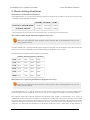
.3
.7
.9
12
13
14
15
15
20
20
22
22
24
26
28
29
31
33
33
35
36
37
39
42
43
44
44
46
46
48
52
60
61
61
62
64
65
66
Pololu Maestro Servo Controller User's Guide
© 2001–2011 Pololu Corporation
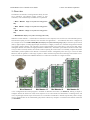
1. Overview
The Maestros are Pololu’s second-generation family of USB
servo controllers. The Maestro family consists of four
controllers, each available fully assembled or as a partial kit:
• Micro Maestro 6 [http://www.pololu.com/catalog/product/
1350]
• Mini Maestro 12 [http://www.pololu.com/catalog/product/
1352]
• Mini Maestro 18 [http://www.pololu.com/catalog/product/
1354]
• Mini Maestro 24 [http://www.pololu.com/catalog/product/1356]
With three control methods — USB for direct connection to a PC computer, TTL serial for use with embedded systems,
and internal scripting for self-contained, host controller-free applications — and channels that can be configured as
servo outputs for use with radio control (RC) servos [http://www.pololu.com/catalog/category/23] or electronic speed controls
(ESCs), digital outputs, or analog/digital inputs, the Maestro is a highly versatile servo controller and general I/O board
in a highly compact package. The extremely precise, high-resolution servo pulses have a jitter of less than 200 ns,
making the Maestro well suited for high-performance animatronics, and built-in speed and acceleration control make
it easy to achieve smooth, seamless movements without requiring the control source to constantly compute and stream
intermediate position updates to the Maestro. The Maestro features configurable pulse rates (up to 333 Hz for Mini
Maestros) and can generate a wide range of pulses to allow maximum responsiveness and range from modern servos.
Units can be daisy-chained with additional Pololu servo and motor controllers on a single serial line.
A free configuration and control program is available for Windows and Linux (see Section 4), making it simple to
configure and test the board over USB, create sequences of servo movements for animatronics or walking robots, and
write, step through, and run scripts stored in the servo controller. The Maestro’s internal script memory allows storage
of servo positions that can be automatically played back without any computer or external microcontroller connected
(see Section 6).
1. Overview
Page 3 of 67
Pololu Maestro Servo Controller User's Guide
© 2001–2011 Pololu Corporation
The Maestros’ channels can also be used as general-purpose digital outputs and analog or digital inputs, providing an
easy way to read sensors and control peripherals directly from a PC over USB. These inputs can be used with the
scripting system to enable creation of self-contained animatronic displays that respond to external stimuli.
A USB A to mini-B cable [http://www.pololu.com/catalog/product/130] (not included) is required to connect this device to a
computer.
1. Overview
Page 4 of 67
Pololu Maestro Servo Controller User's Guide
© 2001–2011 Pololu Corporation
Features
• Three control methods: USB, TTL (5 V) serial, and internal scripting
• 0.25μs output pulse width resolution (corresponds to approximately 0.025° for a typical servo, which is beyond
what the servo could resolve)
• Configurable pulse rate and wide pulse range (see the Maestro comparison table below)
• Individual speed and acceleration control for each channel
• Channels can be optionally configured to go to a specified position or turn off on startup or error
• Alternate channel functions allow the channels to be used as:
◦ General-purpose digital outputs (0 or 5 V)
◦ Analog or digital inputs (channels 0 – 11 can be analog inputs; channels 12+ can be digital inputs)
◦ One channel can be a PWM output with frequency from 2.93 kHz to 12 MHz and up to 10 bits of resolution
(see Section 4.a for details)
• A simple scripting language lets you program the controller to perform complex actions even after its USB and
serial connections are removed
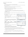
• Free configuration and control application for Windows and
Linux makes it easy to:
◦ Configure and test your controller
◦ Create, run, and save sequences of servo movements for
animatronics and walking robots
◦ Write, step through, and run scripts stored in the servo
controller
• Two ways to write software to control the Maestro from a PC:
◦ Virtual COM port makes it easy to send serial commands from
any development environment that supports serial
communication
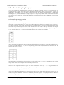
The Channel Settings tab in the Maestro
Control Center.
◦ Pololu
USB
Software
Development
Kit [http://www.pololu.com/docs/0J41] allows use of more advanced
native USB commands and includes example code in C#, Visual
Basic .NET, and Visual C++
• TTL serial features:
◦ Supports 300 – 200,000 bps in fixed-baud mode, 300 –
115,200 bps in autodetect-baud mode
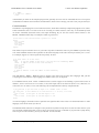
The Status tab in the Maestro Control
Center.
◦ Simultaneously supports the Pololu protocol, which gives
access to advanced functionality, and the simpler Scott Edwards
MiniSSC II protocol (there is no need to configure the device for a particular protocol mode)
◦ Can be daisy-chained with other Pololu servo and motor controllers using a single serial transmit line
◦ Chain input allows reception of data from multiple Mini Maestros using a single serial receive line without
extra components (does not apply to Micro Maestros)
◦ Can function as a general-purpose USB-to-TTL serial adapter for projects controlled from a PC
• Board can be powered off of USB or a 5 – 16 V battery, and it makes the regulated 5V available to the user
• Upgradable firmware
1. Overview
Page 5 of 67
Pololu Maestro Servo Controller User's Guide
© 2001–2011 Pololu Corporation
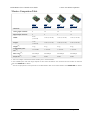
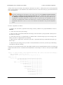
Maestro Comparison Table
Micro
Maestro
Mini
Maestro 12
Mini
Maestro 18
Mini
Maestro 24
Channels:
6
12
18
24
Analog input channels:
6
12
12
12
Digital input channels:
0
0
6
12
Width:
0.85"
(2.16 cm)
1.10" (2.79 cm)
1.10" (2.79 cm)
1.10" (2.79 cm)
Length:
1.20"
(3.05 cm)
1.42" (3.61 cm)
1.80" (4.57 cm)
2.30" (5.84 cm)
Weight(1):
3.0 g
4.2 g
4.9 g
6.0 g
Configurable pulse
rate(2):
33–100 Hz
1–333 Hz
1–333 Hz
1–333 Hz
Pulse range(2):
64–3280 μs
64–4080 μs
64–4080 μs
64–4080 μs
Script size(3):
1 KB
8 KB
8 KB
8 KB
1
This is the weight of the board without header pins or terminal blocks.
The available pulse rate and range depend on each other and factors such as baud rate and number of channels
used. See Section 9 for details.
3
The user script system is more powerful on the Mini Maestro than on the Micro Maestro. See Section 6.d for details.
2
1. Overview
Page 6 of 67
Pololu Maestro Servo Controller User's Guide
© 2001–2011 Pololu Corporation
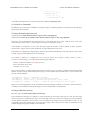
Application Examples
• Serial servo controller for multi-servo projects (e.g. robot arms,
animatronics, fun-house displays) based on microcontroller boards
such
as
the
BASIC
Stamp,
Orangutan
robot
controllers [http://www.pololu.com/catalog/category/8],
or
Arduino
platforms
• Computer-based servo control over USB port
• Computer interface for sensors and other electronics:
◦ Read a gyro [http://www.pololu.com/catalog/product/1266] or
accelerometer [http://www.pololu.com/catalog/product/766] from a
computer for novel user interfaces
◦ Control a string of ShiftBrites [http://www.pololu.com/catalog/
product/1240] from a computer for mood lighting
• General I/O expansion for microcontroller projects
• Programmable, self-contained Halloween or Christmas display
controller that responds to sensors
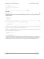
Micro Maestro as the brains of a tiny
hexapod robot.
• Self-contained servo tester
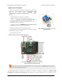
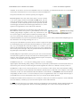
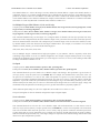
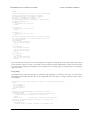
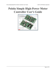
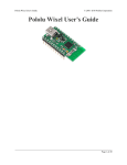
1.a. Micro Maestro Pinout and Components
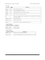
Micro Maestro 6-channel USB servo controller
(fully assembled) labeled top view.
Note: This section applies to the Micro Maestro servo controller. Please see Section 1.b for Mini Maestro
pinout and component information.
The Pololu Micro Maestro 6-channel servo controller can connect to a computer’s USB port via a USB A to miniB cable [http://www.pololu.com/catalog/product/130] (not included). The USB connection is used to configure the servo
1. Overview
Page 7 of 67
Pololu Maestro Servo Controller User's Guide
© 2001–2011 Pololu Corporation
controller. It can also be used to send commands to the servo controller, get information about the servo controller’s
current state, and send and receive TTL serial bytes on the TX and RX lines.
The processor and the servos can have separate power supplies.
Processor power must come either from USB or from an external
5–16V power supply connected to the VIN and GND inputs. It is safe
to have an external power supply connected at the same time that USB
is connected; in such cases the processor will be powered from the
external supply. Note that if the external supply falls below 5 V, correct
operation is not guaranteed, even if USB is also connected.
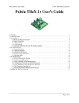
Servo power connections are provided in the upper right corner of the
Micro Maestro board. Servo power is passed directly to the servos
without going through a regulator, so the only restrictions on your
Micro Maestro power pins.
servo power supply are that it must be within the operating range of
your servos and provide enough current for your application. Please
consult the datasheets for your servos to determine an appropriate servo power source, and note that a ballpark figure for
the current draw of an average straining servo is 1 A.
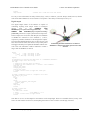
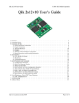
You can power the Maestro’s processor and servos from a single power supply
by connecting the positive power line to both VIN and the servo power ports. An
easy way to accomplish this on the Micro Maestro is to solder a wire on the
bottom of the board between VIN and one of the servo power connections as
shown in the picture to the right.. Only one ground connection is needed because
all ground pins on the board are connected.
The 5V (out) power output allows you to power your own 5V devices from the
on-board 50mA regulator or directly from USB. The on-board regulator is used
whenever VIN is powered; in this case, since the Maestro requires 30 mA, there
is about 20 mA available to power other devices.
Micro Maestro configured to use
a single power supply for both
board and servos.
The SIG lines (0, 1, 2, …) are used for sending pulses to servos, controlling
digital outputs, and measuring analog voltages. These lines are protected by 220Ω resistors. The total current limit (in or
out) for these pins is 60 mA, but when using the on-board regulator the current out is limited to 20 mA (see above.)
The RX line is used to receive non-inverted TTL (0–5 V) serial bytes, such as those from microcontroller UARTs.
These bytes can either be serial commands for the Maestro, arbitrary bytes to send back to the computer via the USB
connection, or both. For more information about the Maestro’s serial interface, see Section 5.a. Note that the Maestro
will probably be able to receive 3.3V TTL serial bytes, but it is not guaranteed to read 3.3V as high on the RX pin, so
you should boost 3.3V TTL serial signals to above 4V if you want to ensure reliable operation.
The TX line transmits non-inverted TTL (0–5 V) serial bytes. These bytes can either be responses to serial commands
sent to the Maestro, or arbitrary bytes sent from the computer via the USB connection.
The RST pin can be driven low to perform a hard reset of the Maestro’s microcontroller, but this should generally not
be necessary for typical applications. The line is internally pulled high, so it is safe to leave this pin unconnected.
1. Overview
Page 8 of 67
Pololu Maestro Servo Controller User's Guide
© 2001–2011 Pololu Corporation
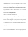
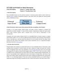
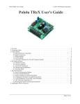
Micro Maestro 6-channel USB servo controller
bottom view with quarter for size reference.
The dimensions of the Micro Maestro PCB are 1.200" × 0.850". The vertical and horizontal distances between the two
mounting holes are 0.650" and 0.575". The Micro Maestro weighs 3.0 g (0.11 oz) without header pins.
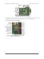
1.b. Mini Maestro Pinout and Components
Mini Maestro 12-channel USB servo controller (fully
assembled) labeled top view.
1. Overview
Page 9 of 67
Pololu Maestro Servo Controller User's Guide
© 2001–2011 Pololu Corporation
Note: This section applies to the Mini Maestro
12, 18, and 24 servo controllers. Please see
Section 1.a for Micro Maestro pinout and
component information.
The Pololu Mini Maestro 12-,18-, and 24-channel
servo controllers can connect to a computer’s USB
port
via
a
USB
A
to
mini-B
cable [http://www.pololu.com/catalog/product/130] (not
included). The USB connection is used to configure
the servo controller. It can also be used to send
commands to the servo controller, get information
about the servo controller’s current state, and send
and receive TTL serial bytes on the TX and RX
lines.
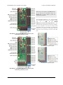
Mini Maestro 18-channel USB servo controller (fully
assembled) labeled top view.
Mini Maestro 12 power pins.
Mini Maestro 18 power pins.
Mini Maestro 24-channel USB servo controller (fully
assembled) labeled top view.
1. Overview
Page 10 of 67
Pololu Maestro Servo Controller User's Guide
© 2001–2011 Pololu Corporation
The processor and the servos can have separate power supplies.
Processor power must come either from USB or from an external
5–16V power supply connected to the VIN and GND inputs on the left
side of the board. It is safe to have an external power supply connected
at the same time that USB is connected; in that case the processor will
be powered from the external supply. Note that if the external supply
falls below 5 V, correct operation is not guaranteed, even if USB is
also connected.
Servo power connections are provided in the lower right corner of the
Mini Maestro board. On the Mini Maestro 18 and 24, you can make
servo power connections via a 2-pin terminal block or a 2-pin 0.1"
header; the Mini Maestro 12 only has a 2-pin 0.1" header for
connecting servo power. Servo power is passed directly to the servos
Mini Maestro 24 power pins.
without going through a regulator, so the only restrictions on your
servo power supply are that it must be within the operating range of
your servos and provide enough current for your application. Please consult the datasheets for your servos to determine
an appropriate servo power source, and note that a ballpark figure for the current draw of an average straining servo is
1 A.
You can power the Maestro’s processor and servos from a single power supply by connecting the positive power line
to both VIN and the servo power ports (only one ground connection is needed because all ground pins on the board are
connected). The recommended way to do this is to connect your power supply to the dedicated servo power pins in the
corner of the board and use the included blue shorting block to connect the pins labeled “VSRV=VIN”.
The 5V (out) power output allows you to power your own 5V devices from the 150mA on-board regulator or directly
from USB. The on-board regulator is used whenever VIN is powered; in this case, since the Maestro requires 50 mA,
there is about 50 mA available to power other devices.
The signal lines (0, 1, 2, …) are used for sending pulses to servos, controlling digital outputs, and measuring voltages.
The total current limit (in or out) for these pins is 150 mA, but when using the on-board regulator the current out is
limited to 50 mA (see above.)
The RX line is used to receive non-inverted TTL (0–5 V) serial bytes, such as those from microcontroller UARTs.
These bytes can either be serial commands for the Maestro, arbitrary bytes to send back to the computer via the USB
connection, or both. For more information about the Maestro’s serial interface, see Section 5.a. Note that the Maestro
will probably be able to receive 3.3V TTL serial bytes, but it is not guaranteed to read 3.3V as high on the RX pin, so
you should boost 3.3V TTL serial signals to above 4V if you want to ensure reliable operation.
The TX line transmits non-inverted TTL (0–5 V) serial bytes. These bytes are either generated by the Mini Maestro
itself (as responses to serial commands or arbitrary bytes sent from the computer via the USB connection), or they come
from the TXIN line.
The RST pin can be driven low to perform a hard reset of the Maestro’s microcontroller, but this should generally not
be necessary for typical applications. The line is internally pulled high, so it is safe to leave this pin unconnected.
The ERR line is an output that is tied to the red error/user LED. It is driven high when the red LED is on, and it is a
pulled low through the red LED when the red LED is off. The red LED turns on when an error occurs, turns off when
the error flags have been cleared, and can also be controlled by the user script. Since the ERR line is never driven low, it
is safe to connect the ERR line of multiple Mini Maestros together. Please note, however, that doing this will cause the
1. Overview
Page 11 of 67
Pololu Maestro Servo Controller User's Guide
© 2001–2011 Pololu Corporation
red LEDs of all connected Mini Maestros to turn on whenever one of the Mini Maestros turns on its red LED. For more
information on the possible error conditions and response options, please see Section 4.b.
The TXIN line is a serial input line that makes it easy to chain together multiple Mini Maestros. Any serial bytes
received on this line will be buffered through an AND gate and transmitted on the TX line. See Section 5.g for more
information about daisy chaining.
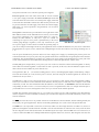
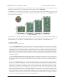
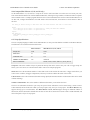
Bottom view with dimensions (in inches) of Pololu Micro and Mini Maestro
servo controllers.
The dimensions of the Mini Maestro PCBs are shown in the picture above, along with the Micro Maestro for
comparison. The vertical and horizontal distances between the two mounting holes are as follows: 1.20" and 0.50" for
the Mini Maestro 12, 1.58" and 0.50" for the Mini Maestro 18, and 1.50" and 0.50" for the Mini Maestro 24.
1.c. Indicator LEDs
The Maestro has three indicator LEDs:
• The green USB LED indicates the USB status of the device. When the Maestro is not connected to a computer
via the USB cable, the green LED will be off. When you connect the Maestro to USB, the green LED will
start blinking slowly. The blinking continues until the Maestro receives a particular message from the computer
indicating that the Maestro’s USB drivers are installed correctly. After the Maestro gets this message, the green
LED will be on, but it will flicker briefly when there is USB activity. The control center application constantly
streams data from the Maestro, so when the control center is running and connected to the Maestro, the green LED
will flicker constantly.
• The red error/user LED usually indicates an error. The red LED turns on when an error occurs, and turns off
when the error flags have been cleared. See Section 4.b for more information about errors. The red LED can also
be controlled by the user script; the red LED will be on if there is an error or if the script command for turning it
on was run.
• The yellow status LED indicates the control status. When the Maestro is in auto-baud detect mode (the default)
and has not yet detected the baud rate, the yellow LED will blink slowly. During this time the Maestro does not
transmit any servo pulses. Once the Maestro is ready to drive servos, the yellow LED will periodically flash briefly.
The frequency of the flashes is proportional to the servo period (the amount of time between pulses on a single
channel); with a period of 20 ms the flashing occurs approximately once per second. On the Micro Maestro, the
number of flashes indicates the state: a single flash indicates that none of the servos are enabled (no pulses are being
sent) and all output channels are low, while a double flash indicates that at least one of the servos is enabled or one
of the output channels is being driven high. The Mini Maestros only emit single flashes. Also, when a valid serial
command is received, the yellow LED will emit a brief, dim flash which ends when the next valid serial command
is received or when the main blinking occurs (whichever happens first).
1. Overview
Page 12 of 67
Pololu Maestro Servo Controller User's Guide
© 2001–2011 Pololu Corporation
When the Maestro is reset in some other way than being initially powered up, the red and/or yellow LEDs blink four
times to indicate the reset condition:
• Yellow off, red blinking: A brownout reset. This occurs when the Maestro’s 5 V line drops below about 3.0 V,
usually due to low batteries or an inadequate power supply.
• Yellow blinking, red off: The Maestro was reset by a low voltage on its RST line.
• Yellow and red blinking together: A firmware crash resulted in a “watchdog” reset. This also occurs immediately
following a firmware upgrade, as a normal part of the upgrade process.
• Yellow blinking, red steady: A firmware error resulted in a soft reset. This should never occur during normal
usage.
1.d. Supported Operating Systems
The Maestro USB drivers and configuration software work under Microsoft Windows XP, Windows Vista, Windows 7,
and Linux.
The Maestro is not compatible with any version of Mac OS.
1. Overview
Page 13 of 67
Pololu Maestro Servo Controller User's Guide
© 2001–2011 Pololu Corporation
2. Contacting Pololu
You can check the product page of your particular Maestro model for additional information. We would be delighted
to hear from you about any of your projects and about your experience with the Maestro. You can contact
us [http://www.pololu.com/contact] directly or post on our forum [http://forum.pololu.com/]. Tell us what we did well, what we
could improve, what you would like to see in the future, or anything else you would like to say!
2. Contacting Pololu
Page 14 of 67
Pololu Maestro Servo Controller User's Guide
© 2001–2011 Pololu Corporation
3. Getting Started
3.a. Installing Windows Drivers and Software
If you are using Windows XP, you will need to have Service Pack 3 [http://www.microsoft.com/downloads/
details.aspx?FamilyId=68C48DAD-BC34-40BE-8D85-6BB4F56F5110] installed before installing the drivers for the
Maestro. See below for details.
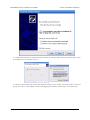
Before you connect your Maestro to a computer running Microsoft Windows, you should install its drivers:
1. Download the Maestro Servo Controller Windows Drivers and Software [http://www.pololu.com/file/download/
maestro_windows_110720.zip?file_id=0J266] (6MB zip)
2. Open the ZIP archive and run setup.exe. The installer will guide you through the steps required to install the
Maestro Control Center, the Maestro command-line utility (UscCmd), and the Maestro drivers on your computer.
If the installer fails, you may have to extract all the files to a temporary directory, right click setup.exe, and select
“Run as administrator”.
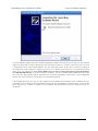
3. During the installation, Windows will warn you that the driver has not been tested by Microsoft and recommend
that you stop the installation. Click “Continue Anyway” (Windows XP) or “Install this driver software anyway”
(Windows 7 and Vista).
4. After the installation is finished, your start menu should have a shortcut to the Maestro Control Center (in
the Pololu folder). This is a Windows application that allows you to configure, control, debug, and get real-time
feedback from the Maestro. There will also be a command-line utility called UscCmd which you can run at a
Command Prompt.
Windows 7 and Windows Vista users: Your computer should now automatically install the necessary drivers when
you connect a Maestro. No further action from you is required.
3. Getting Started
Page 15 of 67
Pololu Maestro Servo Controller User's Guide
© 2001–2011 Pololu Corporation
Windows XP users: Follow steps 5–9 for each new Maestro you connect to your computer.
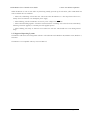
5. Connect the device to your computer’s USB port. The Maestro shows up as three devices in one so your XP
computer will detect all three of those new devices and display the “Found New Hardware Wizard” three
times. Each time the “Found New Hardware Wizard” pops up, follow steps 6-9.
6. When the “Found New Hardware Wizard” is displayed, select “No, not this time” and click “Next”.
7. On the second screen of the “Found New Hardware Wizard”, select “Install the software automatically” and
click “Next”.
3. Getting Started
Page 16 of 67
Pololu Maestro Servo Controller User's Guide
© 2001–2011 Pololu Corporation
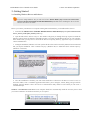
8. Windows XP will warn you again that the driver has not been tested by Microsoft and recommend that you stop
the installation. Click “Continue Anyway”.
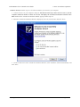
9. When you have finished the “Found New Hardware Wizard”, click “Finish”. After that, another wizard will
pop up. You will see a total of three wizards when plugging in the Maestro. Follow steps 6-9 for each wizard.
3. Getting Started
Page 17 of 67
Pololu Maestro Servo Controller User's Guide
© 2001–2011 Pololu Corporation
If you use Windows XP and experience problems installing or using the serial port drivers, the cause of your problems
might be a bug in older versions of Microsoft’s usb-to-serial driver usbser.sys. Versions of this driver prior to version
5.1.2600.2930 will not work with the Maestro. You can check what version of this driver you have by looking in
the “Details” tab of the “Properties” window for usbser.sys in C:\Windows\System32\drivers. To get the fixed version
of the driver, you will need to install Service Pack 3 [http://www.microsoft.com/downloads/details.aspx?FamilyId=68C48DADBC34-40BE-8D85-6BB4F56F5110]. If you do not want Service Pack 3, you can try installing Hotfix KB918365 instead, but
some users have had problems with the hotfix that were resolved by upgrading to Service Pack 3. The configuration
software will work even if the serial port drivers are not installed properly.
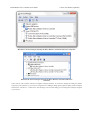
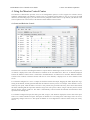
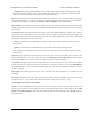
After installing the drivers, if you go to your computer’s Device Manager and expand the “Ports (COM & LPT)” list,
you should see two COM ports: the Command Port and the TTL Port. In parentheses after these names, you will see the
name of the port (e.g. “COM5” or “COM6”). If you expand the “Pololu USB Devices” list you should see an entry for
the Maestro.
3. Getting Started
Page 18 of 67
Pololu Maestro Servo Controller User's Guide
© 2001–2011 Pololu Corporation
Windows 7 device manager showing the Micro Maestro 6-channel USB servo controller.
Windows XP device manager showing the Micro Maestro 6-channel USB servo
controller.
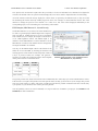
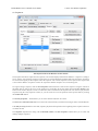
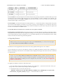
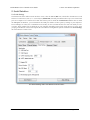
Some software will not allow connection to higher COM port numbers. If you need to change the COM port number
assigned to your USB device, you can do so using the Device Manager. Bring up the properties dialog for the COM port
and click the “Advanced…” button in the “Port Settings” tab. From this dialog you can change the COM port assigned
to your device.
3. Getting Started
Page 19 of 67
Pololu Maestro Servo Controller User's Guide
© 2001–2011 Pololu Corporation
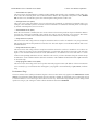
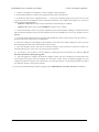
3.b. Installing Linux Drivers and Software
The Maestro Control Center running in Ubuntu Linux.
You can download the Maestro Control Center and the Maestro command-line utility (UscCmd) for Linux here:
• Maestro
Servo
Controller
(112k gz)
Linux
Software [http://www.pololu.com/file/download/
maestro_linux_100507.tar.gz?file_id=0J315]
Unzip the tar/gzip archive by running “tar -xzvf” followed by the name of the file. After following the instructions in
README.txt, you can run the programs by executing MaestroControlCenter and UscCmd.
You can also download the C# source code of UscCmd as part of the Pololu USB Software Development
Kit [http://www.pololu.com/docs/0J41]. Read README.txt in the SDK for more information.
The Maestro’s two virtual serial ports can be used in Linux without any special driver installation. The virtual serial ports
are managed by the cdc-acm kernel module, whose source code you can find in your kernel’s source code drivers/usb/
class/cdc-acm.c. When you connect the Maestro to the PC, the two virtual serial ports should appear as devices with
names like /dev/ttyACM0 and /dev/ttyACM1 (the number depends on how many other ACM devices you have plugged
in). The port with the lower number should be the Command Port, while the port with the higher number should be the
TTL Serial Port. You can use any terminal program (such as kermit) to send and receive bytes on those ports.
3.c. Using the Maestro without USB
It is possible to use the Maestro as a serial servo controller without installing any USB drivers or using a PC. Without
using USB, you will not be able to change the Maestro’s settings, but you can use the default settings which are suitable
for many applications. The default settings that the Maestro ships with are described below.
Default Settings
• The serial mode is “UART, detect baud rate”; after you send the 0xAA baud rate indication byte, the Maestro
will accept TTL-level serial commands on the RX line.
• The Pololu Protocol device number is 12, the Mini SSC offset is 0, and serial timeout and CRC are disabled.
• All channels are configured as servos, with a minimum pulse with of 992 μs and a maximum pulse width of
2000 μs.
• The 8-bit neutral point is 1500 μs and the 8-bit range is 476.25 μs.
3. Getting Started
Page 20 of 67
Pololu Maestro Servo Controller User's Guide
© 2001–2011 Pololu Corporation
• On startup or error, the servos turn off (no pulses are sent).
• On startup, there are no speed or acceleration limits, but you can set speed and acceleration limits using serial
commands.
• The servo period is 20 ms (each servo receives a pulse every 20 ms).
• The user script is empty.
3. Getting Started
Page 21 of 67
Pololu Maestro Servo Controller User's Guide
© 2001–2011 Pololu Corporation
4. Using the Maestro Control Center
The Maestro’s USB interface provides access to all configuration options as well as support for real-time control,
feedback, and debugging. The Maestro Control Center is a graphical tool that makes it easy for you to use the USB
interface; for almost any project, you will want to start by using the control center to set up and test your Maestro. This
section explains most of the features of the Maestro and the Maestro Control Center.
4.a. Status and Real-time Control
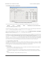
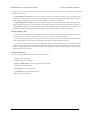
The Status tab in the Maestro Control Center.
The Status tab is used for controlling the Maestro’s outputs and for monitoring its status in real time. A separate row
of controls is displayed for each of the Maestro’s channels. In the screenshot above, there are 12 channels displayed
because the Maestro Control Center is connected to the Mini Maestro 12-channel servo controller. When the Maestro
Control Center connects to Maestro models with more or fewer channels, it displays more or fewer channels on the
screen.
For a channel configured as a servo or output, the checkbox enables the output, dragging the slider adjusts the target
setting of the channel, and the green ball indicates the channel’s current position. For example, if the channel is set to a
relatively slow speed, when the slider is moved to a new position, the green ball will slowly move until it has reached
the slider, indicating that the output has reached its target. For more precise control, a target value may also be entered
directly into the “Target” input box. The slider is automatically scaled to match the minimum and maximum values
specified in the Settings tab.
For a channel configured as input, the slider, green ball, “Target”, and “Position” display the current value of the input.
There is no control available for inputs. The inputs on channels 0–11 are analog: their values range from 0 to 255.75,
representing voltages from 0 to 5 V. The inputs on channels 12–23 are digital: their values are either exactly 0 or exactly
255.75.
4. Using the Maestro Control Center
Page 22 of 67
Pololu Maestro Servo Controller User's Guide
© 2001–2011 Pololu Corporation
The “Speed” and “Acceleration” inputs allow the speed and acceleration of individual servo channels to be adjusted in
real time. The default values are specified in the Settings tab, but it can be useful to adjust them here for fine-tuning.
All of the controls on this tab always display the current values as reported by the Maestro itself, so they are useful
for monitoring the actions caused by another program or device. For example, if a microcontroller uses the TTL serial
interface to change the speed of servo channel 2 to a value of 10, this value will be displayed immediately in the
corresponding input, even if something else was formerly entered there.
PWM Output (Mini Maestro 12, 18, and 24 only)
On the Mini Maestro 12, 18, and 24, one of the channels may
be used as a general-purpose PWM output with a frequency
from 2.93 kHz to 12 MHz and up to 10 bits of resolution.
This could be used, for example, as an input to a motor driver
or for LED brightness control. The PWM output is on
channel 8 for the Mini Maestro 12 and on channel 12 for the
Mini Maestro 18 and 24. This channel must be configured as
an output for PWM to be available.
You may use the PWM Output control at the bottom of the
Status tab to test out PWM, by checking the checkbox and
entering specific values for the on time and period, in units of
1/48 μs. A period of 4800, for example, will generate a
frequency of 10 kHz. The resolution on these values depends
on the period as shown in the table below:
Period
range
The PWM Output control in the Status tab in the
Maestro Control Center (only available on the
Mini Maestro 12, 18, and 24).
Period
On-time
resolution resolution
1–1024
4
1
1025–4096
16
4
4097–16384
64
16
The special periods 1024, 4096, and 16384 are not recommended, since 100% duty cycle is not available at these values.
If the on time is set equal to the period at one of the special values, the duty cycle will be 0% (a low output). The periods
1020 (47.1 kHz), 4080 (11.7 kHz), and 16320 (2.9 kHz) provide the best possible resolution with 100% and 0% duty
cycle options, so you should use one of these periods if possible.
You will probably want to use serial commands or a script to make use of PWM in your project. See Section 5.e and
Section 6.b for more information.
4. Using the Maestro Control Center
Page 23 of 67
Pololu Maestro Servo Controller User's Guide
© 2001–2011 Pololu Corporation
4.b. Errors
The Errors tab in the Maestro Control Center.
The Errors tab indicates problems that the Maestro has detected while running, either communications errors or errors
generated by bugs in a script.
Each error corresponds to a bit in the two-byte error register. The red LED will be on as long as any of the bits in the
error register are set to 1 (it can also be turned on by the led_on script command). The value of the error register is
displayed in the upper right corner of the main window.
When an error occurs, the corresponding bit in the error register is set to 1 and the Maestro sends all of its servos
and digital outputs to their home positions, as specified in the Settings tab (Section 4.e). Any servos or outputs that
are configured to be in the “Ignore” mode will not be changed. The error register is cleared by the “Get Errors” serial
command.
The errors and their corresponding bit numbers are listed below:
• Serial Signal Error (bit 0)
A hardware-level error that occurs when a byte’s stop bit is not detected at the expected place. This can occur if
you are communicating at a baud rate that differs from the Maestro’s baud rate.
• Serial Overrun Error (bit 1)
A hardware-level error that occurs when the UART’s internal buffer fills up. This should not occur during normal
operation.
• Serial RX buffer full (bit 2)
A firmware-level error that occurs when the firmware’s buffer for bytes received on the RX line is full and a byte
from RX has been lost as a result. This error should not occur during normal operation.
4. Using the Maestro Control Center
Page 24 of 67
Pololu Maestro Servo Controller User's Guide
© 2001–2011 Pololu Corporation
• Serial CRC error (bit 3)
This error occurs when the Maestro is running in CRC-enabled mode and the cyclic redundancy check (CRC) byte
at the end of the command packet does not match what the Maestro has computed as that packet’s CRC (Section
5.d). In such a case, the Maestro ignores the command packet and generates a CRC error.
• Serial protocol error (bit 4)
This error occurs when the Maestro receives and incorrectly formatted or nonsensical command packet. For
example, if the command byte does not match a known command or an unfinished command packet is interrupted
by another command packet, this error occurs.
• Serial timeout error (bit 5)
When the serial timeout is enabled, this error occurs whenever the timeout period has elapsed without the Maestro
receiving any valid serial commands. This timeout error can be used to make the servos return to their home
positions in the event that serial communication between the Maestro and its controller is disrupted.
• Script stack error (bit 6)
This error occurs when a bug in the user script has caused the stack to overflow or underflow. Any script command
that modifies the stack has the potential to cause this error. The stack depth is 32 on the Micro Maestro and 126 on
the Mini Maestros.
• Script call stack error (bit 7)
This error occurs when a bug in the user script has caused the call stack to overflow or underflow. An overflow can
occur if there are too many levels of nested subroutines, or a subroutine calls itself too many times. The call stack
depth is 10 on the Micro Maestro and 126 on the Mini Maestros. An underflow can occur when there is a return
without a corresponding subroutine call. An underflow will occur if you run a subroutine using the “Restart Script
at Subroutine” serial command and the subroutine terminates with a return command rather than a quit command
or an infinite loop.
• Script program counter error (bit 8)
This error occurs when a bug in the user script has caused the program counter (the address of the next instruction
to be executed) to go out of bounds. This can happen if you program is not terminated by a quit, return, or infinite
loop.
Performance Flags
The errors tab also shows which performance flags have been set. This feature only applies to the Mini Maestro 12, 18,
and 24. The performance flags indicate that the processor missed a deadline for performing a servo control task, and as
a result the Maestro’s servo control got slowed down in some way. Performance flags should not occur during normal
operation as long as your settings are within with the limitations described in Section 9.
4. Using the Maestro Control Center
Page 25 of 67
Pololu Maestro Servo Controller User's Guide
© 2001–2011 Pololu Corporation
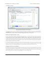
4.c. Sequencer
The Sequence tab in the Maestro Control Center.
The Sequence tab allows simple motion sequences to be created and played back on the Maestro. A sequence is simply a
list of “frames” specifying the positions of each of the servos and a duration (in milliseconds) for each frame. Sequences
are stored in the registry of the computer where the sequence was created. Sequences can be copied to the script, which
is saved on the Maestro. Sequences can also be exported to another computer via a saved settings file.
To begin creating a sequence, click the New Sequence button and enter a name for the sequence. Using the controls in
the Status tab, set each of the servos to the position you would like for the first frame, then click Save Frame at the
bottom of the window. Repeat to create several frames, then switch back to the Sequence tab. You can now play back the
sequence using the “Play Sequence” button, or you can set the servos to the positions of the specific frame by clicking
the Load Frame button.
The Frame properties… button allows you to set the duration and name of a frame.
The Save Over Current Frame button overwrites the selected frame(s) with the current target values from the Maestro.
If the Play in a loop checkbox is checked, sequence playback will loop back to the beginning of the sequence whenever
it reaches the end.
The Sequence dropdown box along with the Rename, Delete, and New Sequence buttons allow you to create and
manage multiple sequences.
4. Using the Maestro Control Center
Page 26 of 67
Pololu Maestro Servo Controller User's Guide
© 2001–2011 Pololu Corporation
A sequence can also be used to create a script which is stored on the Maestro. There are two buttons for copying the
sequence into the script:
• Copy Sequence to Script sets the script to a looped version of the sequence. In most cases, you will also want
to check the “Run script on startup” option in the Script tab so that the script runs automatically when the Maestro
is powered up, enabling fully automatic operation without a connection to a computer.
• Copy all Sequences to Script is an advanced option that adds a set of subroutines to the end of the current script.
Each subroutine represents one of the sequences; calling the subroutine from the script will cause the sequence to
be played back a single time. These subroutines must be used together with custom script code; for example, you
could make a display in which a button connected to an input channel triggers a sequence to play back.
Sequence Editing Tips
• You can select multiple frames by holding down the Ctrl or Shift buttons while clicking on them. This allows
you to quickly move, delete, set the duration of, cut, copy, or save over several frames at once.
• You can drag any of the tabs out of the main window in to their own windows. If you drag the Sequence tab out
of the window then you will be able to see the Status tab and the Sequence tab at the same time.
• You can cut, copy, and paste frames by selecting them and then using the Edit menu or the standard keyboard
shortcuts. Frames are stored on the clipboard as tab-separated text, so you can cut them from the frame list, paste
them in to a spreadsheet program, edit them, and then copy them back in to the frame list when you are done. (This
feature does not work in Linux.)
Keyboard Shortcuts
The following keyboard shortcuts can be used in the frame list:
• Ctrl+A: Select all frames.
• Ctrl+C: Copy selected frames.
• Ctrl+V or Shift+Insert: Paste/insert frames from clipboard.
• Ctrl+X: Cut selected frames.
• Ctrl+Up: Move selected frames up.
• Ctrl+Down: Move selected frames down.
• Del: Delete selected frames.
4. Using the Maestro Control Center
Page 27 of 67
Pololu Maestro Servo Controller User's Guide
© 2001–2011 Pololu Corporation
4.d. Entering a Script
The Script tab in the Maestro Control Center.
The Script tab is where you enter a script to be loaded into the Maestro. For details on the Maestro scripting language,
see Section 6. Once you have entered a script and clicked the “Apply Settings” button to load the script on to the device,
there are a number of options available for testing and debugging your script on the Script tab.
Running and stepping through a script
To start a script running, click the green button labeled “Run Script”. Your script will be processed by the Maestro,
one instruction at a time, until a QUIT instruction is reached or an error occurs. In many cases it will be useful to use
a loop of some kind to cause a script to run forever. While the script is running, the red “Stop Script” button will be
available, and the small pink triangle will jump around your source code, showing you the instruction that is currently
being executed. If the script places data on the stack, it will be visible on the right side of the tab, and nested subroutine
calls are counted in a label at the top of the tab.
To examine the operation of a script in more detail, click the blue button labeled “Step Script”. This button causes the
script to execute a single instruction, then stop and wait for another command. By stepping through the script a single
instruction at a time, you can check that each part of your program does exactly what you expect it to do.
Setting the script to be run on startup
By default, the script only runs when you click the “Run Script” button. However, for many applications, you will want
the script to run automatically, so that the Maestro can be used without a permanent USB connection. Check the “Run
script on startup” option to cause the Maestro to automatically run the script whenever it is powered up. You will still be
able to use the controls on the Script tab to for debugging or to stop the running script.
4. Using the Maestro Control Center
Page 28 of 67
Pololu Maestro Servo Controller User's Guide
© 2001–2011 Pololu Corporation
Examining the compiled code
Click the “View Compiled Code” button to see the actual bytes that are created by each line of your script. This is
available mostly as a tool for developers; if you are interested in the details of the bytecode used on the Maestro (for
example, if you want to write your own compiler), please contact us [http://www.pololu.com/contact]. At the end of the
compiled code is a listing of all of the subroutines, including their numbers in decimal and hex notation. These numbers
can be used with serial commands to enter the subroutines under external control.
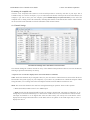
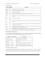
4.e. Channel Settings
The Channel Settings tab in the Maestro Control Center.
The Channel Settings tab contains controls for many of the channel-related parameters that are stored on the Maestro,
affecting its operation immediately on start-up.
A separate row of controls is displayed for each of the Maestro’s channels:
Name. Each of the channels may be assigned a name, for your convenience. Channel names are not stored on the device
but instead in the system registry on your conmputer; if you want to use your Maestro on a different computer without
losing the names, save a settings file on the old computer and load it into the Maestro with the new one.
Mode. The mode of the channel is the most basic setting determining its operation. There are three options:
• Servo (the default) indicates an R/C servo PWM output.
• Input specifies that the channel should be used as an analog or digital input. The inputs on channels 0–11 are
analog: they are measured continuously as a value between 0 and 1023 (VCC), at a maximum rate of about 20 kHz.
The inputs on channels 12–23 are digital: their values are either exactly 0 or exactly 1023. Note that the values
displayed in the Target and Position boxes in the Status tab are one quarter of the actual input value, so 1023 is
displayed as 255.75.
4. Using the Maestro Control Center
Page 29 of 67
Pololu Maestro Servo Controller User's Guide
© 2001–2011 Pololu Corporation
• Output specifies that the channel should be used as a simple digital output. Instead of indicating a pulse width,
the position value of the channel is used to control whether the output is low (0 V) or high (VCC). Specifically, the
output is low unless the position value is greater than or equal to 1500.00 μs.
Rate specifies the pulse rate for each Servo channel. On the Micro Maestro 6, all servos must have the save pulse rate,
while on the Mini Maestro 12, 18, an 24, you can have two different rates and choose which rate to use on each channel.
The pulse rates available are controlled by the Period and Period multiplier settings described below.
Min and Max specify the allowed values for the channel’s position. For channels configured as Servo outputs, the Min
and Max settings correspond respectively to the minimum and maximum allowed pulse widths for the servo, in units of
microseconds.
On startup or error. This option specifies what value the target of the channel should have when the device starts up
(power-up or reset) or when there is an error. Note that if there is a speed or acceleration setting for the channel, the
output will smoothly transition to the specified position on an error, but not during start-up, since it has no information
about the previous position of the servo in this case.
• Off specifies that the servo should initially be off (have a value of 0), and that it should be turned off whenever
an error occurs.
• Ignore specifies that the servo should initially be off, but that its value should not change on error.
• Go to specifies a default position for the servo. The servo target will be set to this position on start-up or when
an error occurs.
Speed. This option specifies the speed of the servo in units of 0.25 μs / (10 ms). For example, with a speed of 4, the
position will change by at most 1 μs per 10 ms, or 100.00 μs/s. Mini Maestro 12, 18, and 24 only: If you use a period
other than the default 20 ms, the units of speed are different. See below for more information.
Acceleration. This option specifies the acceleration of the servo in units of (0.25 μs) / (10 ms) / (80 ms). For example,
with an acceleration of 4, the speed of the servo will change by a maximum of 1250 μs/s every second. Mini Maestro
12, 18, and 24 only: If you use a period other than the default 20 ms, the units of acceleration are different. See below
for more information.
8-bit neutral. This option specifies the target value, in microseconds, that corresponds to 127 (neutral) for 8-bit
commands.
8-bit range. This option specifies the range of target values accesible with 8-bit commands. An 8-bit value of 0 results
in a target of neutral – range, while an 8-bit value of 254 results in a target value of neutral + range.
Advanced pulse control options are available:
Period is an advanced option that sets the period of all of the servo pulses, in milliseconds. This is the amount of time
between successive pulses on a given channel. If you are unsure about this option, leave it at the default of 20 ms. Mini
Maestro 12, 18, and 24 only: the units of speed and acceleration depend on the pulse rate. The units depend only on
Period, not on Period multiplier. Please refer to the following table for the relationship between Period and speed/
acceleration units:
4. Using the Maestro Control Center
Page 30 of 67
Pololu Maestro Servo Controller User's Guide
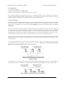
Period (T)
Rate
T = 20 ms
50 Hz
Speed units
Acceleration units
(0.25 μs)/(10 ms) (0.25 μs)/(10 ms)/(80 ms)
T = 3–19 ms > 50 Hz (0.25 μs)/T
T > 20 ms
© 2001–2011 Pololu Corporation
< 50 Hz (0.25 μs)/(T/2)
(0.25 μs)/T/(8T)
(0.25 μs)/(T/2)/(4T)
Servos available is an advanced option for the Micro Maestro only specifying the number of channels that may be used
to control servos. For example, if this value is set to 4, only the channels 0–3 will be available as servo channels. The
other channels must all be set to Input or Output. The only reasons to make fewer servos available are to allow a longer
maximum pulse length or a shorter period.
Period multiplier is an advanced option for the Mini Maestro 12, 18, and 24 that allows a larger period (lower pulse
rate) on some of the channels. For example, if you select a period of 3 and a multiplier of 6, you can have some servos
run at 3 ms (333 Hz) and the others at 18 ms (55 Hz). When the multiplier is greater than 1, the pulse rate options will
be shown in each channel in the Rate column.
For the Mini Maestro 24-channel servo controller, one extra option is available:
Enable pull-ups on channels 18-20 turns on pull-up resistors for all of the channels 18-20 that are configured as inputs.
This guarantees that the input value will be high when nothing else is driving the line. When enabled, this feature allows
you to connect buttons or switches to channels 18, 19, or 20 without supplying your own external pull-up resistor: simply
connect the button/switch between ground and signal line.
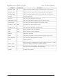
4.f. Upgrading Firmware
Note: There have been no firmware upgrades released for the Mini Maestros yet, so this section only applies
to the Micro Maestro 6-Channel USB Servo Controller.
The Maestro has field-upgradeable firmware that can be easily updated with bug fixes or new features.
You can determine the version of your Maestro’s firmware by running the Maestro Control Center, connecting to a
Maestro, and looking at the firmware version number which is displayed in the upper left corner next to the “Connected
to” dropdown box.
Version 1.01 of the Micro Maestro 6-channel servo controller firmware contains a bug-fix that makes
“Ignore” mode servos behave correctly at startup. The update is recommended for devices with an earlier
firmware version number, including all devices shipped before November 19, 2009. Do not apply this
update to a Mini Maestro!
To upgrade your Maestro’s firmware, follow these steps:
1. Save the settings stored on your Maestro using the “Save settings file…” option in the File menu. All of your
settings will be reset to default values during the firmware upgrade.
2. Download the latest version of the firmware here:
◦ Firmware version 1.01 for the Micro Maestro 6-channel servo controller [http://www.pololu.com/file/
download/usc02a_v1.01.pgm?file_id=0J280] (35k pgm) — released November 19, 2009
4. Using the Maestro Control Center
Page 31 of 67
Pololu Maestro Servo Controller User's Guide
© 2001–2011 Pololu Corporation
3. Connect your Maestro to a Windows or Linux computer using a USB cable.
4. Run the Pololu Maestro Control Center application and connect to the Maestro.
5. In the Device menu, select “Upgrade firmware…”. You will see a message asking you if you are sure you want
to proceed: click OK. The Maestro will now disconnect itself from your computer and reappear as a new device
called “Pololu usc02a Bootloader”.
◦ Windows 7 and Vista: the driver for the bootloader will automatically be installed.
◦ Windows XP: follow steps 6–8 from Section 3.a to get the driver working.
6. Once the bootloader’s drivers are properly installed, the green LED should be blinking in a double heart-beat
pattern, and there should be an entry for the bootloader in the “Ports (COM & LPT)” list of your computer’s Device
Manager.
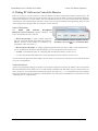
7. Go to the window titled “Firmware Upgrade” that the Maestro Control Center opened. Click the “Browse…”
button and select the firmware file you downloaded.
8. Select the COM port corresponding to the bootloader. If you don’t know which COM port to select, go to the
Device Manager and look in the “Ports (COM & LPT)” section.
9. Click the “Program” button. You will see a message warning you that your device’s firmware is about to be
erased and asking you if you are sure you want to proceed: click Yes.
10. It will take a few seconds to erase the Maestro’s existing firmware and load the new firmware. Do not
disconnect the Maestro during the upgrade.
11. Once the upgrade is complete, the Firmware Upgrade window will close, the Maestro will disconnect from
your computer once again, and it will reappear as it was before. If there is only one Maestro plugged in to your
computer, the Maestro Control Center will connect to it. Check the firmware version number and make sure that it
now indicates the latest version of the firmware.
If you run into problems during a firmware upgrade, please contact us [http://www.pololu.com/contact] for assistance.
4. Using the Maestro Control Center
Page 32 of 67
Pololu Maestro Servo Controller User's Guide
© 2001–2011 Pololu Corporation
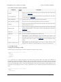
5. Serial Interface
5.a. Serial Settings
The Maestro has three different serial interfaces. First, it has the TX and RX lines, which allow the Maestro to send
and receive non-inverted, TTL (0 – 5 V) serial bytes (Section 5.b). Secondly, the Maestro shows up as two virtual serial
ports on a computer if it is connected via USB. One of these ports is called the Command Port and the other is called
the TTL port. In Windows, you can determine the COM port numbers of these ports by looking in your computer’s
Device Manager. In Linux, the Command Port will usually be /dev/ttyACM0 and the TTL Port will usually be /dev/
ttyACM1. These numbers may be different on your computer depending on how many serial devices are active when
you plug in the Maestro. This section explains the serial interface configurations options available in the Serial Settings
tab of the Maestro Control Center.
The Serial Settings tab in the Maestro Control Center.
5. Serial Interface
Page 33 of 67
Pololu Maestro Servo Controller User's Guide
© 2001–2011 Pololu Corporation
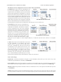
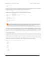
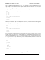
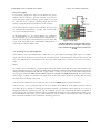
The Maestro can be configured to be in one of three basic serial modes:
USB Dual Port: In this mode, the Command Port can
be used to send commands to the Maestro and receive
responses from it. The baud rate you set in your terminal
program when opening the Command Port is irrelevant.
The TTL Port can be used to send bytes on the TX line
and receive bytes on the RX line. The baud rate you set
in your terminal program when opening the TTL Port
determines the baud rate used to receive and send bytes
The USB Dual Port serial mode.
on RX and TX. This allows your computer to control the
Maestro and simultaneously use the RX and TX lines as
a general purpose serial port that can communicate with other types of TTL serial devices.
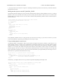
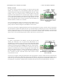
USB Chained: In this mode, the Command Port is
used to both transmit bytes on the TX line and send
commands to the Maestro. The Maestro’s responses
to those commands will be sent to the Command
Port but not the TX line. Bytes received on the RX
line will be sent to the Command Port but will not be
interpreted as command bytes by the Maestro. The
baud rate you set in your terminal program when
opening the Command Port determines the baud rate
The USB Chained serial mode.
used to receive and send bytes on RX and TX. The
TTL Port is not used. This mode allows a single
COM port on your computer to control multiple Maestros, or a Maestro and other devices that have a compatible
protocol.
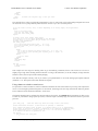
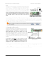
UART: In this mode, the TX and RX lines can be used
to send commands to the Maestro and receive
responses from it. Any byte received on RX will be
sent to the Command Port, but bytes sent from the
Command Port will be ignored. The TTL Port is not
used. The baud rate on TX and RX can either be
automatically detected by the Maestro when a 0xAA
byte is received on RX, or it can be set to a fixed value
The UART serial mode.
specified in bits per second (bps). This mode allows
you to control the Maestro (and send bytes to a serial
program on the computer) using a microcontroller or other TTL serial device.
Other serial settings:
Enable CRC: If checked, the Maestro will require a cyclic redundancy check (CRC) byte at the end of every serial
command except the Mini SSC command (see Section 5.d).
Device Number: This is the device number (0–127) that is used to address this device in Pololu Protocol commands.
This setting is useful when using the Maestro with other devices in a daisy-chained configuration (see Section 5.g).
Mini SSC offset: This parameter determines which servo numbers the device will respond to in the Mini SSC protocol
(see Section 5.e).
Timeout: This parameter specifies the duration before which a Serial timeout error will occur. This error can be used
as a safety measure to ensure that your servos and digital outputs go back to their default states whenever the software
5. Serial Interface
Page 34 of 67
Pololu Maestro Servo Controller User's Guide
© 2001–2011 Pololu Corporation
sending commands to the Maestro stops working. The serial timeout error will occur whenever no valid serial commands
(or qualifying native USB commands) are received within the specified timeout period. A timeout period of 0.00
disables the serial timeout error. The resolution of this parameter is 0.01 s and the maximum value available is 655.35 s.
The native USB commands that qualify correspond to the following methods in the Usc class: setTarget, setSpeed,
setAcceleration, setPwm, disablePWM, and clearErrors. Running the Maestro Control Center will not prevent the
serial timeout error from occurring, but setting targets in the Status tab or playing a sequence will.
Never sleep (ignore USB suspend): By default, the Maestro’s processor will go to sleep and stop all of its operations
whenever it detects that it is only powered by USB (no VIN supply) and that the USB has entered the Suspend State.
However, this behavior can be disabled by checking the Never sleep checkbox.
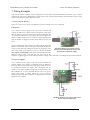
5.b. TTL Serial
The Maestro’s serial receive line, RX, can receive bytes when connected to a logic-level (0 to 4.0–5 V, or “TTL”), noninverted serial signal. The bytes sent to the Maestro on RX can be commands to the Maestro or an arbitrary stream
of data that the Maestro passes on to a computer via the USB port, depending on which serial mode the Maestro is in
(Section 5.a). The voltage on the RX pin should not go below 0 V and should not exceed 5 V.
The Maestro provides logic-level (0 to 5 V) serial output on its serial transmit line, TX. The bytes sent by the Maestro on
TX can be responses to commands that request information or an arbitrary stream of data that the Maestro is receiving
from a computer via the USB port and passing on, depending on which Serial Mode the Maestro is in. If you aren’t
interested in receiving TTL serial bytes from the Maestro, you can leave the TX line disconnected.
The serial interface is asynchronous, meaning that the sender and receiver each independently time the serial bits.
Asynchronous TTL serial is available as hardware modules called “UARTs” on many microcontrollers. Asynchronous
serial output can also be “bit-banged” by a standard digital output line under software control.
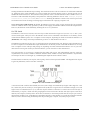
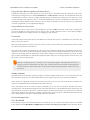
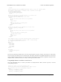
The data format is 8 data bits, one stop bit, with no parity, which is often expressed as 8-N-1. The diagram below depicts
a typical asynchronous, non-inverted TTL serial byte:
Diagram of a non-inverted TTL serial byte.
A non-inverted TTL serial line has a default (non-active) state of high. A transmitted byte begins with a single low “start
bit”, followed by the bits of the byte, least-significant bit (LSB) first. Logical ones are transmitted as high (VCC) and
logical zeros are transmitted as low (0 V), which is why this format is referred to as “non-inverted” serial. The byte is
terminated by a “stop bit”, which is the line going high for at least one bit time. Because each byte requires a start bit, 8
data bits, and a stop bit, each byte takes 10 bit times to transmit, so the fastest possible data rate in bytes per second is
the baud rate divided by ten. At the Maestro’s maximum baud rate of 250,000 bits per second, the maximum realizable
data rate, with a start bit coming immediately after the preceding byte’s stop bit, is 25,000 bytes per second.
5. Serial Interface
Page 35 of 67
Pololu Maestro Servo Controller User's Guide
© 2001–2011 Pololu Corporation
Whenever connecting devices, remember to wire the grounds together, and ensure that each device is
properly powered. Unpowered devices with a TTL serial port can turn on or partially on, drawing power
from the serial line, which means that extra care must be taken when turning power off and on to reset
the devices.
5.c. Command Protocols
You can control the Maestro by issuing serial commands.
If your Maestro’s serial mode is “UART, detect baud rate”, you must first send it the baud rate indication byte 0xAA on
the RX line before sending any commands. The 0xAA baud rate indication byte can be the first byte of a Pololu protocol
command.
The Maestro serial command protocol is similar to that of other Pololu products. Communication is achieved by sending
command packets consisting of a single command byte followed by any data bytes that command requires. Command
bytes always have their most significant bits set (128–255, or 0x80–0xFF in hex) while data bytes always have their
most significant bits cleared (0–127, or 0x00–0x7F in hex). This means that each data byte can only transmit seven bits
of information. The only exception to this is the Mini SSC command, where the data bytes can have any value from 0 to
254.
The Maestro responds to three sub-protocols:
Compact Protocol
This is the simpler and more compact of the two protocols; it is the protocol you should use if your Maestro is the only
device connected to your serial line. The Maestro compact protocol command packet is simply:
command byte (with MSB set), any necessary data bytes
For example, if we want to set the target of servo 0 to 1500 µs, we could send the following byte sequence:
in hex: 0x84, 0x00, 0x70, 0x2E
in decimal: 132, 0, 112, 46
The byte 0x84 is the Set Target command, the first data byte 0x00 is the servo number, and the last two data bytes
contain the target in units of quarter-microseconds.
Pololu Protocol
This protocol is compatible with the serial protocol used by our other serial motor and servo controllers. As such, you
can daisy-chain a Maestro on a single serial line along with our other serial controllers (including additional Maestros)
and, using this protocol, send commands specifically to the desired Maestro without confusing the other devices on the
line.
To use the Pololu protocol, you transmit 0xAA (170 in decimal) as the first (command) byte, followed by a Device
Number data byte. The default Device Number for the Maestro is 12, but this is a configuration parameter you can
change. Any Maestro on the line whose device number matches the specified device number accepts the command that
follows; all other Pololu devices ignore the command. The remaining bytes in the command packet are the same as the
compact protocol command packet you would send, with one key difference: the compact protocol command byte is
5. Serial Interface
Page 36 of 67
Pololu Maestro Servo Controller User's Guide
© 2001–2011 Pololu Corporation
now a data byte for the command 0xAA and hence must have its most significant bit cleared. Therefore, the command
packet is:
0xAA, device number byte, command byte with MSB cleared, any necessary data bytes
For example, if we want to set the target of servo 0 to 1500 µs for a Maestro with device number 12, we could send the
following byte sequence:
in hex: 0xAA, 0x0C, 0x04, 0x00, 0x70, 0x2E
in decimal: 170, 12, 4, 0, 112, 46
Note that 0x04 is the command 0x84 with its most significant bit cleared.
Mini SSC Protocol
The Maestro also responds to the protocol used by the Mini SSC servo controller. This protocol allows you to control
up to 254 different servos by chaining multiple servo controllers together. It only takes three serial bytes to set the target
of one servo, so this protocol is good if you need to send many commands rapidly. The Mini SSC protocol is to transmit
0xFF (255 in decimal) as the first (command) byte, followed by a servo number byte, and then the 8-bit servo target
byte. Therefore, the command packet is:
0xFF, servo number byte, servo target byte
For example, if we wanted to set the target of servo 0 to its (configurable) neutral position, we could send the following
byte sequence:
in hex: 0xFF, 0x00, 0x7F
in decimal: 255, 0, 127
The Maestro can be configured to respond to any contiguous block of Mini SSC servo numbers from 0 to 254.
The Maestro identifies the Pololu, Compact, and Mini-SSC protocols on the fly; you do not need to use a configuration
parameter to identify which protocol you are using, and you can freely mix commands in the three protocols.
5.d. Cyclic Redundancy Check (CRC) Error Detection
For certain applications, verifying the integrity of the data you are sending and receiving can be very important. Because
of this, the Maestro has optional 7-bit cyclic redundancy checking, which is similar to a checksum but more robust as it
can detect errors that would not affect a checksum, such as an extra zero byte or bytes out of order.
Cyclic redundancy checking can be enabled by checking the “Enable CRC” checkbox in the “Serial Settings” tab of the
Maestro Control Center application. In CRC mode, the Maestro expects an extra byte to be added onto the end of every
command packet (except Mini SSC command packets). The most-significant bit of this byte must be cleared, and the
seven least-significant bits must be the 7-bit CRC for that packet. If this CRC byte is incorrect, the Maestro will set the
Serial CRC error bit in the error register and ignore the command. The Maestro does not append a CRC byte to the data
it transmits in response to serial commands.
A detailed account of how cyclic redundancy checking works is beyond the scope of this document, but you can find
a wealth of information using Wikipedia [http://en.wikipedia.org/wiki/Cyclic_redundancy_check]. The CRC computation is
basically a carryless long division of a CRC “polynomial”, 0x91, into your message (expressed as a continuous stream
5. Serial Interface
Page 37 of 67
Pololu Maestro Servo Controller User's Guide
© 2001–2011 Pololu Corporation
of bits), where all you care about is the remainder. The Maestro uses CRC-7, which means it uses an 8-bit polynomial
and, as a result, produces a 7-bit remainder. This remainder is the lower 7 bits of the CRC byte you tack onto the end of
your command packets.
The CRC implemented on the Maestro is the same as the one on the jrk [http://www.pololu.com/catalog/
product/1392] and qik [http://www.pololu.com/catalog/product/1110] motor controller but differs from that on
the TReX [http://www.pololu.com/catalog/product/777] motor controller. Instead of being done MSB first, the
computation is performed LSB first to match the order in which the bits are transmitted over the
serial line. In standard binary notation, the number 0x91 is written as 10010001. However, the bits are
transmitted in this order: 1, 0, 0, 0, 1, 0, 0, 1, so we will write it as 10001001 to carry out the computation
below.
The CRC-7 algorithm is as follows:
1. Express your 8-bit CRC-7 polynomial and message in binary, LSB first. The polynomial 0x91 is written as
10001001.
2. Add 7 zeros to the end of your message.
3. Write your CRC-7 polynomial underneath the message so that the LSB of your polynomial is directly below
the LSB of your message.
4. If the LSB of your CRC-7 is aligned under a 1, XOR the CRC-7 with the message to get a new message; if the
LSB of your CRC-7 is aligned under a 0, do nothing.
5. Shift your CRC-7 right one bit. If all 8 bits of your CRC-7 polynomial still line up underneath message bits, go
back to step 4.
6. What’s left of your message is now your CRC-7 result (transmit these seven bits as your CRC byte when talking
to the Maestro with CRC enabled).
If you have never encountered CRCs before, this probably sounds a lot more complicated than it really is. The following
example shows that the CRC-7 calculation is not that difficult. For the example, we will use a two-byte sequence: 0x83,
0x01.
Steps 1 & 2 (write as binary, least significant bit first, add 7 zeros to the end of the message):
CRC-7 Polynomial = [1 0 0 0 1 0 0 1]
message = [1 1 0 0 0 0 0 1] [1 0 0 0 0 0 0 0] 0 0 0 0 0 0 0
Steps 3, 4, & 5:
_______________________________________________
1 0 0 0 1 0 0 1 ) 1 1 0 0 0 0 0 1 1 0 0 0 0 0 0 0 0 0 0 0 0 0 0
XOR 1 0 0 0 1 0 0 1 | | | | | | | | | | | | | | |
--------------- | | | | | | | | | | | | | | |
1 0 0 1 0 0 0 1 | | | | | | | | | | | | | |
shift ----> 1 0 0 0 1 0 0 1 | | | | | | | | | | | | | |
_______________ | | | | | | | | | | | | | |
1 1 0 0 0 0 0 0 | | | | | | | | | | |
1 0 0 0 1 0 0 1 | | | | | | | | | | |
_______________ | | | | | | | | | | |
1 0 0 1 0 0 1 0 | | | | | | | | | |
1 0 0 0 1 0 0 1 | | | | | | | | | |
_______________ | | | | | | | | | |
1 1 0 1 1 0 0 0 | | | | | | |
1 0 0 0 1 0 0 1 | | | | | | |
_______________ | | | | | | |
1 0 1 0 0 0 1 0 | | | | | |
1 0 0 0 1 0 0 1 | | | | | |
_______________ | | | | | |
1 0 1 0 1 1 0 0 | | | |
5. Serial Interface
Page 38 of 67
Pololu Maestro Servo Controller User's Guide
© 2001–2011 Pololu Corporation
1 0 0 0 1 0 0 1 | |
_______________ | |
1 0 0 1 0 1 0 0
1 0 0 0 1 0 0 1
_______________
1 1 1 0 1
|
|
|
|
|
0
|
|
|
|
|
0 = 0x17
So the full command packet we would send with CRC enabled is: 0x83, 0x01, 0x17.
5.e. Serial Servo Commands
The Maestro has several serial commands for setting the target of a channel, getting its current position, and setting its
speed and acceleration limits.
Set Target (Pololu/Compact protocol)
Compact protocol: 0x84, channel number, target low bits, target high bits
Pololu protocol: 0xAA, device number, 0x04, channel number, target low bits, target high bits
The lower 7 bits of the third data byte represent bits 0–6 of the target (the lower 7 bits), while the lower 7 bits of the
fourth data byte represent bits 7–13 of the target. The target is a non-negative integer.
If the channel is configured as a servo, then the target represents the pulse width to transmit in units of quartermicroseconds. A target value of 0 tells the Maestro to stop sending pulses to the servo.
If the channel is configured as a digital output, values less than 6000 tell the Maestro to drive the line low, while values
of 6000 or greater tell the Maestro to drive the line high.
For example, if channel 2 is configured as a servo and you want to set its target to 1500 µs (1500×4 = 6000 =
01011101110000 in binary), you could send the following byte sequence:
in binary: 10000100, 00000010, 01110000, 00101110
in hex: 0x84, 0x02, 0x70, 0x2E
in decimal: 132, 2, 112, 46
Here is some example C code that will generate the correct serial bytes, given an integer “channel” that holds the channel
number, an integer “target” that holds the desired target (in units of quarter microseconds if this is a servo channel) and
an array called serialBytes:
serialBytes[0]
serialBytes[1]
serialBytes[2]
serialBytes[3]
=
=
=
=
0x84; // Command byte: Set Target.
channel; // First data byte holds channel number.
target & 0x7F; // Second byte holds the lower 7 bits of target.
(target >> 7) & 0x7F;
// Third data byte holds the bits 7-13 of target.
Many servo control applications do not need quarter-microsecond target resolution. If you want a shorter and lowerresolution set of commands for setting the target you can use the Mini-SSC command below.
Set Target (Mini SSC protocol)
Mini-SSC protocol: 0xFF, channel address, 8-bit target
This command sets the target of a channel to a value specified by an 8-bit target value from 0 to 254. The 8-bit target
value is converted to a full-resolution target value according to the range and neutral settings stored on the Maestro
for that channel. Specifically, an 8-bit target of 127 corresponds to the neutral setting for that channel, while 0 or 254
correspond to the neutral setting minus or plus the range setting. These settings can be useful for calibrating motion
without changing the program sending serial commands.
5. Serial Interface
Page 39 of 67
Pololu Maestro Servo Controller User's Guide
© 2001–2011 Pololu Corporation
The channel address is a value in the range 0–254. By default, the channel address is equal to the channel number, so
it should be from 0 to 23. To allow multiple Maestros to be controlled on the same serial line, set the Mini SSC Offset
parameter to different values for each Maestro. The Mini SSC Offset is added to the channel number to compute the
correct channel address to use with this command. For example, a Micro Maestro 6-channel servo controller with a Mini
SSC Offset of 12 will obey Mini-SSC commands whose address is within 12–17.
Set Multiple Targets (Mini Maestro 12, 18, and 24 only)
Compact protocol: 0x9F, number of targets, first channel number, first target low bits, first target high bits, second
target low bits, second target high bits, …
Pololu protocol: 0xAA, device number, 0x1F, number of targets, first channel number, first target low bits, first
target high bits, second target low bits, second target high bits, …
This command simultaneously sets the targets for a contiguous block of channels. The first byte specifies how many
channels are in the contiguous block; this is the number of target values you will need to send. The second byte specifies
the lowest channel number in the block. The subsequent bytes contain the target values for each of the channels, in order
by channel number, in the same format as the Set Target command above. For example, to set channel 3 to 0 (off) and
channel 4 to 6000 (neutral), you would send the following bytes:
0x9F, 0x02, 0x03, 0x00, 0x00, 0x70, 0x2E
The Set Multiple Targets command allows high-speed updates to your Maestro, which is especially useful when
controlling a large number of servos in a chained configuration. For example, using the Pololu protocol at 115.2 kbps,
sending the Set Multiple Targets command lets you set the targets of 24 servos in 4.6 ms, while sending 24 individual
Set Target commands would take 12.5 ms.
Set Speed
Compact protocol: 0x87, channel number, speed low bits, speed high bits
Pololu protocol: 0xAA, device number, 0x07, channel number, speed low bits, speed high bits
This command limits the speed at which a servo channel’s output value changes. The speed limit is given in units of
(0.25 μs)/(10 ms), except in special cases (see Section 4.e). For example, the command 0x87, 0x05, 0x0C, 0x01 sets
the speed of servo channel 5 to a value of 140, which corresponds to a speed of 3.5 μs/ms. What this means is that
if you send a Set Target command to adjust the target from, say, 1000 μs to 1350 μs, it will take 100 ms to make that
adjustment. A speed of 0 makes the speed unlimited, so that setting the target will immediately affect the position. Note
that the actual speed at which your servo moves is also limited by the design of the servo itself, the supply voltage, and
mechanical loads; this parameter will not help your servo go faster than what it is physically capable of.
At the minimum speed setting of 1, the servo output takes 40 seconds to move from 1 to 2 ms.
The speed setting has no effect on channels configured as inputs or digital outputs.
Set Acceleration
Compact protocol: 0x89, channel number, acceleration low bits, acceleration high bits
Pololu protocol: 0xAA, device number, 0x09, channel number, acceleration low bits, acceleration high bits
This command limits the acceleration of a servo channel’s output. The acceleration limit is a value from 0 to 255 in
units of (0.25 μs)/(10 ms)/(80 ms), except in special cases (see Section 4.e). A value of 0 corresponds to no acceleration
limit. An acceleration limit causes the speed of a servo to slowly ramp up until it reaches the maximum speed, then
to ramp down again as position approaches target, resulting in a relatively smooth motion from one point to another.
With acceleration and speed limits, only a few target settings are required to make natural-looking motions that would
otherwise be quite complicated to produce.
5. Serial Interface
Page 40 of 67
Pololu Maestro Servo Controller User's Guide
© 2001–2011 Pololu Corporation
At the minimum acceleration setting of 1, the servo output takes about 3 seconds to move smoothly from a target of
1 ms to a target of 2 ms.
The acceleration setting has no effect on channels configured as inputs or digital outputs.
Set PWM (Mini Maestro 12, 18, and 24 only)
Compact protocol: 0x8A, on time low bits, on time high bits, period low bits, period high bits
Pololu protocol: 0xAA, device number, 0x0A, on time low bits, on time high bits, period low bits, period high bits
This command sets the PWM output to the specified on time and period, in units of 1/48 μs. The on time and period
are both encoded with 7 bits per byte in the same way as the target in command 0x84, above. For more information on
PWM, see Section 4.a. The PWM output is not available on the Micro Maestro.
Get Position
Compact protocol: 0x90, channel number
Pololu protocol: 0xAA, device number, 0x10, channel number
Response: position low 8 bits, position high 8 bits
This command allows the device communicating with the Maestro to get the position value of a channel. The position
is sent as a two-byte response immediately after the command is received.
If the specified channel is configured as a servo, this position value represents the current pulse width that the Maestro
is transmitting on the channel, reflecting the effects of any previous commands, speed and acceleration limits, or scripts
running on the Maestro.
If the channel is configured as a digital output, a position value less than 6000 means the Maestro is driving the line low,
while a position value of 6000 or greater means the Maestro is driving the line high.
If the channel is configured as an input, the position represents the voltage measured on the channel. The inputs on
channels 0–11 are analog: their values range from 0 to 1023, representing voltages from 0 to 5 V. The inputs on channels
12–23 are digital: their values are either exactly 0 or exactly 1023.
Note that the formatting of the position in this command differs from the target/speed/acceleration formatting in the
other commands. Since there is no restriction on the high bit, the position is formatted as a standard little-endian twobyte unsigned integer. For example, a position of 2567 corresponds to a response 0x07, 0x0A.
Note that the position value returned by this command is equal to four times the number displayed in the Position box
in the Status tab of the Maestro Control Center.
Get Moving State
Compact protocol: 0x93
Pololu protocol: 0xAA, device number, 0x13
Response: 0x00 if no servos are moving, 0x01 if servos are moving
This command is used to determine whether the servo outputs have reached their targets or are still changing, limited
by speed or acceleration settings. Using this command together with the Set Target command, you can initiate several
servo movements and wait for all the movements to finish before moving on to the next step of your program.
5. Serial Interface
Page 41 of 67
Pololu Maestro Servo Controller User's Guide
© 2001–2011 Pololu Corporation
Get Errors
Compact protocol: 0xA1
Pololu protocol: 0xAA, device number, 0x21
Response: error bits 0-7, error bits 8-15
Use this command to examine the errors that the Maestro has detected. Section 4.b lists the specific errors that can be
detected by the Maestro. The error register is sent as a two-byte response immediately after the command is received,
then all the error bits are cleared. For most applications using serial control, it is a good idea to check errors continuously
and take appropriate action if errors occur.
Go Home
Compact protocol: 0xA2
Pololu protocol: 0xAA, device number, 0x22
This command sends all servos and outputs to their home positions, just as if an error had occurred. For servos and
outputs set to “Ignore”, the position will be unchanged.
Note: For servos marked “Off”, if you execute a Set Target command immediately after Go Home, it
will appear that the servo is not obeying speed and acceleration limits. In fact, as soon as the servo is
turned off, the Maestro has no way of knowing where it is, so it will immediately move to any new target.
Subsequent target commands will function normally.
5.f. Serial Script Commands
The Maestro has several serial commands for controlling the execution of the user script.
Stop Script
Compact protocol: 0xA4
Pololu protocol: 0xAA, device number, 0x24
This command causes the script to stop, if it is currently running.
Restart Script at Subroutine
Compact protocol: 0xA7, subroutine number
Pololu protocol: 0xAA, device number, 0x27, subroutine number
This command starts the script running at a location specified by the subroutine number argument. The subroutines are
numbered in the order they are defined in your script, starting with 0 for the first subroutine. The first subroutine is
sent as 0x00 for this command, the second as 0x01, etc. To find the number for a particular subroutine, click the “View
Compiled Code…” button and look at the list below. Subroutines used this way should not end with the RETURN
command, since there is no place to return to — instead, they should contain infinite loops or end with a QUIT
command.
Restart Script at Subroutine with Parameter
Compact protocol: 0xA8, subroutine number, parameter low bits, parameter high bits
Pololu protocol: 0xAA, device number, 0x28, subroutine number, parameter low bits, parameter high bits
This command is just like the Restart Script at Subroutine command, except it loads a parameter on to the stack before
starting the subroutine. Since data bytes can only contain 7 bits of data, the parameter must be between 0 and 16383.
5. Serial Interface
Page 42 of 67
Pololu Maestro Servo Controller User's Guide
© 2001–2011 Pololu Corporation
Get Script Status
Compact protocol: 0xAE
Pololu protocol: 0xAA, device number, 0x2E
Response: 0x00 if the script is running, 0x01 if the script is stopped
This command responds with a single byte, either 0 or 1, to indicate whether the script is running (0) or stopped (1).
Using this command together with the commands above, you can activate a sequence stored on the Maestro and wait
until the sequence is complete before moving on to the next step of your program.
5.g. Daisy Chaining
This section is a guide to integrating the Maestro in to a project that has multiple TTL serial devices that use a compatible
protocol. This section contains no new information about the Maestro: all of the information in this section can be
deduced from the definitions of the three serial modes (Section 5.a) and the serial protocols used by the Maestro
(Section 5.c).
First of all, you will need to decide whether to use the Pololu protocol, the Mini SSC protocol, or a mix of both. You
must make sure that no serial command you send will cause unintended operations on the devices it was not addressed
to. If you want to daisy chain several Maestros together, you can use a mixture of both protocols. If you want to daisy
chain the Maestro with other devices that use the Pololu protocol, you can use the Pololu protocol. If you want to daisy
chain the Maestro with other devices that use the Mini SSC protocol, you can use the Mini SSC protocol.
Secondly, assign each device in the project a different device number or Mini SSC offset so that they can be individually
addressed by your serial commands. For the Maestro, this can be done in the Serial Settings tab of the Maestro Control
Center application.
The following diagram shows how to connect one master and many slave devices together into a chain. Each
of the devices may be a Maestro or any other device, such as a jrk [http://www.pololu.com/catalog/product/1392],
qik [http://www.pololu.com/catalog/product/1110] or other microcontroller.
Daisy chaining serial devices using the Pololu
protocol. An optional AND gate is used to join
multiple TX lines.
The Mini Maestro 12, 18, and 24 have a special input called TXIN that eliminates the need for an external AND gate
(the AND gate is built in to the Maestro.) To make a chain of devices using the TXIN input, connect them like this:
Daisy chaining serial devices that have a TXIN input.
5. Serial Interface
Page 43 of 67
Pololu Maestro Servo Controller User's Guide
© 2001–2011 Pololu Corporation
Using a PC and a Maestro together as the master device
The Maestro can enable a personal computer to be the master device. The Maestro must be connected to a PC with a
USB cable and configured to be in either USB Dual Port or USB Chained serial mode. In USB Dual Port mode, the
Command Port on the PC is used for sending commands directly to the Maestro, and the TTL Port on the PC is used
to send commands to all of the slave devices. In the USB Chained mode, only the Command Port is used on the PC to
communicate with the Maestro and all of the slave devices. Select the mode that is most convenient for your application
or easiest to implement in your programming language.
Using a Maestro as a slave device
The Maestro can act as a slave device when configured to be in the UART serial mode. In this mode, commands are
received on the RX line, and responses are sent on the TX line. A USB connection to a PC is not required, though an
RX-only Comand Port is available on the PC for debugging or other purposes.
Connections
Connect the TX line of the master device to the RX lines of all of the slave devices. Commands sent by the master will
then be received by all slaves.
Receiving serial responses from one of the slave devices on the PC can be achieved by connecting the TX line of that
slave device to the RX line of the Maestro.
Receiving serial responses from multiple slave devices is more complicated. Each device should only transmit when
requested, so if each device is addressed separately, multiple devices will not transmit simultaneously. However, the TX
outputs are driven high when not sending data, so they cannot simply be wired together. Instead, you can use an AND
gate, as shown in the diagram, to combine the signals. Note that in many cases receiving responses is not necessary, and
the TX lines can be left unconnected.
Whenever connecting devices, remember to wire the grounds together, and ensure that each device is
properly powered. Unpowered devices with a TTL serial port can turn on or partially on, drawing power
from the serial line, which means that extra care must be taken when turning power off and on to reset
the devices.
Sending commands
The Pololu Protocol or Mini SSC protocol should be used when multiple Pololu devices are receiving the same serial
data. This allows the devices to be individually addressed, and it allows responses to be sent without collisions.
If the devices are configured to detect the baud rate, then when you issue your first Pololu Protocol command, the
devices can automatically detect the baud from the initial 0xAA byte.
Some older Pololu devices use 0x80 as an initial command byte. If you want to chain these together with devices
expecting 0xAA, you should first transmit the byte 0x80 so that these devices can automatically detect the baud rate, and
only then should you send the byte 0xAA so that the Maestro can detect the baud rate. Once all devices have detected
the baud rate, Pololu devices that expect a leading command byte of 0x80 will ignore command packets that start with
0xAA, and the Maestro will ignore command packets that start with 0x80.
5.h. Serial Example Code
5.h.1. PIC18F4550
The following example code for the PIC18F4550 was submitted to us by customer Ney Palma Castillo. It is intended
to be compiled with the PIC MCU C Compiler [http://www.ccsinfo.com/content.php?page=compilers]. The code shows how to
5. Serial Interface
Page 44 of 67
Pololu Maestro Servo Controller User's Guide
© 2001–2011 Pololu Corporation
control a Maestro via serial commands using pins C6 and C7. It first commands the channel 0 servo to go to its minimum
position and then, one second later, to go to its neutral position. Please see Section 5.e for information on connecting the
PIC to the Maestro and set the Maestro’s serial mode to “UART, detect baud rate.”
#include<18f4550.H>
#fuses HSPLL, NOMCLR, PUT, BROWNOUT, BORV43, NOWDT, NOPROTECT, NOLVP
#fuses NODEBUG, USBDIV, PLL5, CPUDIV1, VREGEN, CCP2B3
#use delay(clock=48000000)
#define TTL_TX1 PIN_C6
#define TTL_RX1 PIN_C7
#use rs232(xmit=TTL_TX1, rcv=TTL_RX1, bits=8, parity=N)
void main() {
delay_ms(2000);
while(true) {
// Send a Set Target command using the Pololu protocol.
putc(0xAA); // Start Byte
putc(0x0C); // Device ID = 12
putc(0x04); // Command = Set Target
putc(0x00); // Channel = 0
putc(0x20); // Target position = 1000 us (typical minimum for servos)
putc(0x1F);
delay_ms(1000);
}
}
// Send another Set Target command using the Pololu protocol.
putc(0xAA);
putc(0x0C);
putc(0x04);
putc(0x00);
putc(0x70); // Target position = 1500 us (typical neutral for servos)
putc(0x2E);
delay_ms(1000);
5. Serial Interface
Page 45 of 67
Pololu Maestro Servo Controller User's Guide
© 2001–2011 Pololu Corporation
6. The Maestro Scripting Language
A script is a sequence of commands that is executed by the Maestro. Commands can set servo targets, speeds, and
accelerations, retrieve input values, and perform mathematical computations. Basic control structures – looping and
conditionals – are available for use in making complicated scripts. The Maestro script language is a simple stackbased language very similar to FORTH, and scripts compile to a compact bytecode in which commands and subroutine
calls each take just a single byte. A basic editor/debugger is available in the Script tab of the Maestro Control Center
application.
6.a. Maestro Script Language Basics
Commands and the stack
A program in the Maestro script language consists of a sequence of commands which act on a stack of values. Values
in the stack are integers from -32768 to +32767. On the Micro Maestro 6-channel servo controller, there is room for up
to 32 values on the stack, while on the Mini Maestro servo controllers there is room for up to 126 values on the stack.
Commands always act on the topmost values of the stack and leave their results on the top of the stack. The simplest
kind of commands are literals, numerical values that are placed directly onto the stack. For example, the program “-10
20 35 0” puts the values -10, 20, 35, and 0 sequentially onto the stack, so that it looks like this:
value
3
0
2
35
1
20
0
-10
A more complicated command is the PLUS command, which adds the top two numbers, leaving the result on the top of
the stack. Suppose the numbers 1, 2, 4, and 7 are sequentially placed on the stack, and the PLUS command is run. The
following table shows the result:
before after
3
7
2
4
11
1
2
2
0
1
1
Note that the PLUS command always decreases the size of the stack by one. It is up to you to make sure that you have
enough values on the stack to complete the commands you want to run!
Consider a more complicated example: suppose we want to compute the value of (1 – 3) × 4, using the MINUS and
MULTIPLY commands. The way to write this computation as a script is “1 3 MINUS 4 TIMES”.
Comments, case, whitespace, and line breaks
All parts of the Maestro script language are case-insensitive, and you may use any kind of whitespace (spaces, tabs, and
newlines) to separate commands. Comments are indicated by the pound sign “#” – everything from the # to the end of
the line will be ignored by the compiler. For example, the computation above may be written as:
6. The Maestro Scripting Language
Page 46 of 67
Pololu Maestro Servo Controller User's Guide
© 2001–2011 Pololu Corporation
1 3 miNUS
4 # this is a comment!
times
with absolutely no effect on the compiled program. We generally use lower-case for commands and two or four spaces
of indentation to indicate control structures and subroutines, but feel free to arrange your code to suit your personal style.
Control structures
The Maestro script language has several control structures, which allow arbitrarily complicated programs to be written.
Unlike subroutines, there is no limit to the level of nesting of control structures, since they are all ultimately based
on GOTO commands (discussed below) and simple branching. By far the most useful control structure is the
BEGIN…REPEAT infinite loop, an example of which is given below:
# move servo 1 back and forth with a period of 1 second
begin
8000 1 servo
500 delay
4000 1 servo
500 delay
repeat
This infinite loop will continue forever. If you want a loop that is bounded in some way, the WHILE keyword is likely
to be useful. WHILE consumes the top number on the stack and jumps to the end of the loop if and only if it is a zero.
For example, suppose we want to repeat this loop exactly 10 times:
10 # start with a 10 on the
begin
dup
# copy the number
while
# jump to the end
8000 1 servo
500 delay
4000 1 servo
500 delay
1 minus # subtract 1 from
repeat
stack
on the stack - the copy will be consumed by WHILE
if the count reaches 0
the number of times remaining
Note that BEGIN…WHILE…REPEAT loops are similar to the while loops of many other languages. But, just like
everything else in the Maestro script language, the WHILE comes after its argument.
For conditional actions, an IF…ELSE…ENDIF structure is useful. Suppose we are building a system with a sensor on
channel 3, and we want to set servo 5 to 6000 (1.5 ms) if the input value is less than 512 (about 2.5 V). Otherwise, we
will set the servo to 7000 (1.75 ms). The following code accomplishes this relatively complicated task:
3 get_position
512 less_than
if
6000 5 servo
else
7000 5 servo
endif
# get the value of input 3 as a number from 0 to 1023
# test whether it is less than 512 -> 1 if true, 0 if false
# this part is run when input3 < 512
# this part is run when input3 >= 512
As in most languages, the ELSE section is optional. Note again that this seems at first to be backwards relative to other
languages, since the IF comes after the test.
The WHILE and IF structures are enough to create just about any kind of script. However, there are times when it is just
not convenient to think about what you are trying to do in terms of a loop or a branch. If you just want to jump directly
from one part of code to another, you may use a GOTO. It works like this:
6. The Maestro Scripting Language
Page 47 of 67
Pololu Maestro Servo Controller User's Guide
© 2001–2011 Pololu Corporation
goto mylabel
# ...any code here is skipped...
4000 1 servo
mylabel: # the program continues here
4000 2 servo
In this example, only servo 2 will get set to 4000, while servo 1 will be unchanged.
Subroutines
It can be useful to use the same sequence of commands many times throughout your program. Subroutines are used
to make this easier and more space-efficient. For example, suppose you often need to set servo 1 and servo 2 back to
their neutral positions of 6000 (1.5 ms) using the sequence “6000 1 servo 6000 2 servo”. You can encapsulate this in a
subroutine as follows:
sub neutral
6000 1 servo
6000 2 servo
return
Then, whenever you want send these two servos back to neutral, you can just use “neutral” as a command. More
advanced subroutines take values off of the stack. For example, the subroutine
sub set_servos
2 servo 1 servo
return
will set channel 2 to the value on the top of the stack and channel 1 to the next value. So, if you write “4000 6000
set_servos”, your script will set channel 1 to 4000 and channel 2 to 6000.
Subroutines can call other subroutines, up to a limit of 10 levels of recursion. For example, the subroutine “neutral”
above can be implemented by calling set_servos:
sub neutral
6000 6000 set_servos
return
6.b. Command Reference
The following is the entire list of commands and keywords in the Maestro script language. The “stack effect” column
specifies how many numbers are consumed and added to the stack. For example, the PLUS command takes off two
numbers and returns one; so it has a stack effect of -2,+1. Commands with special effects will be marked with a *.
6. The Maestro Scripting Language
Page 48 of 67
Pololu Maestro Servo Controller User's Guide
© 2001–2011 Pololu Corporation
Keywords
stack
effect
keyword
description
BEGIN
none
marks the beginning of a loop
ENDIF
none
ends a conditional block IF…ENDIF
ELSE
none
begins the alternative block in IF…ELSE…ENDIF
GOTO
label
none
goes to the label label (define it with label:)
IF
-1
enters the conditional block if the argument is true (non-zero) in IF…ENDIF or
IF…ELSE…ENDIF
REPEAT
none
marks the end of a loop
SUB name none
defines a subroutine name
WHILE
jumps to the end of a loop if the argument is false (zero)
-1
Control commands
command stack effect
description
QUIT
none
stops the script
RETURN
none
ends a subroutine
Timing commands
command stack effect
description
DELAY
-1
delays by the given number of milliseconds
GET_MS
+1
gets the current millisecond timer (wraps around from 32767 to -32768)
6. The Maestro Scripting Language
Page 49 of 67
Pololu Maestro Servo Controller User's Guide
© 2001–2011 Pololu Corporation
Stack commands
command
stack
effect
DEPTH
+1
gets the number of numbers on the stack
DROP
-1
removes the top number from the stack
DUP
+1
duplicates the top number
OVER
+1
duplicates the number directly below the top, copying it onto the top
PICK
-1,+1
takes a number n, then puts the nth number below the top onto the stack (0 PICK is equivalent
to DUP)
SWAP
a,b →
swaps the top two numbers
b,a
ROT
a,b,c
→
b,c,a
permutes the top three numbers so that the 3rd becomes the top and the others move down one
position
ROLL
-1,*
takes a number n, then permutes the top n+1 numbers so that the n+1th becomes the top and all
of the others move down one
PEEK
-1,+1
(Mini Maestro 12, 18, and 24 only) takes a number n, then copies the nth value on the stack
(measured from the bottom) to the top of the stack
POKE
-2,+1
(Mini Maestro 12, 18, and 24 only) takes a number n, then removes the next value from the
stack and puts it at the nth location on the stack (measured from the bottom)
description
Mathematical commands (unary)
These commands take a single argument from the top of the stack, then return a single value as a result. Some of these
have equivalents in C (and most other languages), listed in the “C equivalent” column below. We use “false” to mean 0
and “true” to mean any non-zero value. A command returning “true” always returns a 1.
command
BITWISE_NOT
C equivalent
~
description
inverts all of the bits in its argument
LOGICAL_NOT !
replaces true by false, false by true
NEGATE
–
replaces x by -x
POSITIVE
none
true if and only if the argument is greater than zero
NEGATIVE
none
true if and only if the argument is less than zero
NONZERO
none
true (1) if and only if the argument is true (non-zero)
Mathematical commands (binary)
These commands take two arguments from the top of the stack, then return a single value as a result. The order of the
arguments, when important, is the standard one in mathematics; for example, to compute 1 – 2, you write “1 2 MINUS”.
These commands all have equivalents in C (and most other languages), listed in the “C equivalent” column below.
6. The Maestro Scripting Language
Page 50 of 67
Pololu Maestro Servo Controller User's Guide
command
C equivalent
© 2001–2011 Pololu Corporation
description
BITWISE_AND
&
applies the boolean AND function to corresponding bits of the arguments
BITWISE_OR
|
applies the boolean OR function to corresponding bits of the arguments
BITWISE_XOR
^
applies the boolean XOR function to corresponding bits of the arguments
DIVIDE
/
divides the arguments
EQUALS
=
true if and only if the arguments are equal
GREATER_THAN >
true if and only if the first argument is greater than the second
LESS_THAN
<
true if and only if the first argument is less than the second
LOGICAL_AND
&&
true if and only if both arguments are true
LOGICAL_OR
||
true if and only if at least one argument is true
MAX
none
selects the greater of the two arguments
MIN
none
selects the lesser of the two arguments
MINUS
–
subtracts the arguments
MOD
%
computes the remainder on division of the first argument by the second
NOT_EQUALS
!=
true if and only if the arguments are not equal
PLUS
+
adds the arguments
SHIFT_LEFT
<<
shifts the binary representation of the second argument to the left by a number
of bits given in the second argument (without wrapping)
SHIFT_RIGHT
>>
shifts the binary representation of the first argument to the right by a number of
bits given in the second argument (without wrapping)
TIMES
*
multiplies the arguments
6. The Maestro Scripting Language
Page 51 of 67
Pololu Maestro Servo Controller User's Guide
© 2001–2011 Pololu Corporation
Servo, LED, and other output commands
command
stack
effect
description
SPEED
-2
sets the speed of the channel specified by the top element to the value in the second
element (see Section 4.e)
ACCELERATION
-2
sets the acceleration of the channel specified by the top element to the value in the
second element (see Section 4.e)
GET_POSITION
-1,+1
gets the position of the channel specified by the top element
GET_MOVING_STATE +1
true if any servos are still moving, limited by speed or acceleration
SERVO
-2
sets the target of the channel specified by the top element to the value in the second
element, in units of 0.25 μs
SERVO_8BIT
-2
sets the target of the channel specified by the top element to the value in the second
element, which should be a value from 0 to 254 (see the Mini SSC command in
Section 5.e)
LED_ON
none
turns the red LED on
LED_OFF
none
turns the red LED off (assuming no errors bits are set)
PWM
-2
(Mini Maestro 12, 18, and 24 only) enables the PWM output channel, with
the period specified by the top element and the on time specified by the second
element, both in units of 1/48 μs (see Section 4.a for more information about
PWM)
SERIAL_SEND_BYTE
-1
(Mini Maestro 12, 18, and 24 only) removes the top number from the stack,
interprets it as a single byte, and sends that byte to the TTL serial output (TX)
6.c. Example Scripts
Getting started: blinking an LED
The following script will cause the red LED on the Maestro to blink once per second:
# Blinks the red LED once per second.
begin
led_on
100 delay
led_off
900 delay
repeat
It is a good idea to try stepping through this script before doing anything further with scripts on the Maestro. In
particular, pay attention to how the command “100” puts the number 100 on the stack, and the DELAY command
consumes that number. In the Maestro scripting language, arguments to commands always need to be placed on the stack
before the commands that use them, which makes the language seem backwards compared to other languages. It also
means that you can arrange your code in a variety of different ways. For example, this program is equivalent to the one
above:
# Blinks the red LED once per second.
begin
900 100
led_on delay
6. The Maestro Scripting Language
Page 52 of 67
Pololu Maestro Servo Controller User's Guide
© 2001–2011 Pololu Corporation
led_off delay
repeat
The numbers are placed on the stack at the beginning of the loop, then consumed later on in execution. Pay attention to
the order of the numbers used here: the 900 goes on the stack first, and it is used last.
A simple servo sequence
The following script shows how to direct servo 0 to five different positions in a loop.
# Move servo 0
begin
4000 0 servo
500 delay
5000 0 servo
500 delay
6000 0 servo
500 delay
7000 0 servo
500 delay
8000 0 servo
500 delay
repeat
to five different positions, in a loop.
# set servo 0 to 1.00 ms
# 1.25 ms
# 1.50 ms
# 1.75 ms
# 2.00 ms
The serial mode must not be set to detect baud rate for this script to work. In detect baud rate mode, the
Maestro does not enable any of the servo outputs until the start byte has been received.
Note that the servo positions are specified in units of 0.25 μs, so a value of 4000 corresponds to 1 ms. The text after the #
is a comment; it does not get programmed on to the device, but it can be useful for making notes about how the program
works. Good comments are essential for complicated programs. It is important to remember the DELAY commands;
without these, the script will not wait at all between servo commands, running the loop hundreds of times per second.
Compressing the sequence
The program above takes 58 bytes of program space: 11 bytes for each servo position and 3 for the loop. At this rate,
we could store up to 92 servo positions in the 1024-byte memory of the Micro Maestro, or 744 servo positions in the
8192-byte memory of the Mini Maestros. To get the most out of the limited memory, there are a variety of ways to
compress the program. Most important is to make use of subroutines. For example, since we repeat the instructions “0
servo 500 delay” several times, we can move them into a subroutine to save space. At the same, this simplifies the code
and makes it easier to make future modifications, such as changing the speed of the entire sequence.
# Move servo 0 to five different positions, in a loop.
begin
4000
frame
5000
frame
6000
frame
7000
frame
8000
frame
repeat
sub frame
0 servo
500 delay
return
6. The Maestro Scripting Language
Page 53 of 67
Pololu Maestro Servo Controller User's Guide
© 2001–2011 Pololu Corporation
Using the subroutine brings the script down to 31 bytes: 4 per position and 11 bytes of overhead for the loop and to
define FRAME. We can go further: inspecting the compiled code shows that putting each number on the stack requires
3 bytes: one byte as a command, and two for the two-byte number. Numbers from 0 to 255 can be loaded onto the stack
with just two bytes. Suppose in our application we do not need the full 0.25 μs resolution of the device, since all of our
settings are multiples of 100. Then we can use smaller numbers to save another byte:
# Move servo 0 to five different positions, in a loop.
begin
40 frame
50 frame
60 frame
70 frame
80 frame
repeat
# loads a frame specified in 25 us units
sub frame
100 times
0 servo
500 delay
return
This program is 29 bytes long, with 3 bytes used per position and 14 bytes of overhead. Note that we could get the same
efficiency if we used the SERVO_8BIT command, which takes a one-byte argument from 0 to 254. We can go even
smaller by putting all of the numbers together:
# Move servo 0 to five different positions, in a loop.
begin
80 70 60 50 40
frame frame frame frame frame
repeat
# loads a frame specified in 25 us units
sub frame
100 times
0 servo
500 delay
return
If you step through this version program, you will also notice that all five numbers are placed on the stack in a single
step: this is because the compiler can use a single command to put multiple numbers on the stack. Using a single
command for multiple numbers saves space: we are now down to just 26 bytes. Only 12 bytes are used for the 5 frames,
for an average of 2.4 bytes per frame. This is probably compact enough – by duplicating this structure we could fit 420
different positions into the 1024-byte program memory of the Micro Maestro. However, the code can get even smaller.
Consider this script, which uses 31 frames to make a smooth back-and-forth motion:
# Moves servo in a sine wave between 1 and 2 ms.
begin
60 64 68 71 74 77 79 80 80 79 78 76 73 70 66 62
58 54 50 47 44 42 41 40 40 41 43 46 49 52 56
all_frames
repeat
sub all_frames
begin
depth
while
100 times
0 servo
100 delay
repeat
return
In this version of the code, we have rewritten the FRAME subroutine, using the DEPTH command to automatically load
frames from the stack until there are none left. This program uses 34 bytes to store 31 frames, for an average of just
6. The Maestro Scripting Language
Page 54 of 67
Pololu Maestro Servo Controller User's Guide
© 2001–2011 Pololu Corporation
1.1 bytes per frame. We could store a sequence containing 900 different positions in the memory of the Micro Maestro
using this kind of script.
Making smooth sequences with GET_MOVING_STATE
Speed and acceleration settings can be used to make smooth motion sequences with the Maestro. However, a common
problem is that you do not know how much you need to delay between frames to allow the servo to reach its final
position. Here is an example of how to use the built-in function GET_MOVING_STATE to make a smooth sequence,
instead of DELAY:
# This example uses speed and acceleration to make a smooth
# motion back and forth between 1 and 2 ms.
3 0 acceleration
30 0 speed
begin
4000 0 servo # set servo 0 to 1.00 ms
moving_wait
8000 0 servo # 2.00 ms
moving_wait
repeat
sub moving_wait
begin
get_moving_state
while
# wait until it is no longer moving
repeat
return
GET_MOVING_STATE returns a 1 as long as there is at least one servo moving, so you can use it whenever you want
to wait for all motion to stop before proceeding to the next step of a script.
Using an analog input to control servos
An important feature of the Maestro is that it can be used to read inputs from sensors, switches, or other devices. As a
simple example, suppose we want to use a potentiometer to control the position of a servo. For this example, connect
the potentiometer to form a voltage divider between 5V and 0, with the center tap connected to channel 1. Configure
channel 1 to be an input, and examine the signal on the Status tab of the Maestro Control Center. You should see the
position indicator vary from 0 to 255 μs as you turn the potentiometer from one side to the other. In your script, this
range corresponds to numbers from 0 to 1023. We can scale this number up to approximately the full range of a servo,
then set the servo position to this number, all in a loop:
# Sets servo 0 to a
begin
1 get_position
4 times 4000 plus
0 servo
repeat
position based on an analog input.
# get the value of the pot, 0-1023
# scale it to 4000-8092, approximately 1-2 ms
# set servo 0 based to the value
Alternatively, you might want the servo to go to discrete positions depending on the input value:
# Set the servo to 4000, 6000, or 8000 depending on an analog input.
begin
1 get_position
# get the value of the pot, 0-1023
dup 300 less_than
if
4000
# go to 4000 for values 0-299
else
dup 600 less_than
if
6000 # go to 6000 for values 300-599
else
8000 # go to 8000 for values 600-1023
6. The Maestro Scripting Language
Page 55 of 67
Pololu Maestro Servo Controller User's Guide
endif
endif
0 servo
drop
repeat
© 2001–2011 Pololu Corporation
# remove the original copy of the pot value
The example above works, but when the potentiometer is close to 300 or 600, noise on the analog-to-digital conversion
can cause the servo to jump randomly back and forth. A better way to do it is with hysteresis:
# Set the servo to 4000, 6000, or 8000 depending on an analog input, with hysteresis.
begin
4000 0 300 servo_range
6000 300 600 servo_range
8000 600 1023 servo_range
repeat
# usage: <pos> <low> <high> servo_range
# If the pot is in the range specified by low and
# keeps servo 0 at pos until the pot moves out of
# range, with hysteresis.
sub servo_range
pot 2 pick less_than logical_not
# >= low
pot 2 pick greater_than logical_not # <= high
logical_and
if
begin
pot 2 pick 10 minus less_than logical_not
pot 2 pick 10 plus greater_than logical_not
logical_and
while
2 pick 0 servo
repeat
endif
drop drop drop
return
high,
this
# >= low - 10
# <= high + 10
sub pot
1 get_position
return
This example uses one range for deciding where to go when making a transition, then it waits for the servo to leave a
slightly larger range before making another transition. As long as the difference (10 in this example) is larger than the
amount of noise, this will prevent the random jumping.
Note that this example will only work if you connect your potentiometer to one of the analog input capable channels
(channels 0–11). The inputs on the other channels are digital.
Using a button or switch to control servos
It is possible to connect a button or switch to a Maestro and detect the state of the button in your script. The script below
moves a servo through a predefined sequence of movements, advancing to the next step each time the button is pushed.
It uses channel 0 for the button and channel 1 for the servo.
The button channel must be configured as an input and wired correctly. See Section 7.b for instructions on how to wire
a button to your Maestro using a pull-up resistor, so that the input is normally high, and when the button is pressed it
goes low.
goto main_loop
# Run the main loop when the script starts (see below).
# This subroutine returns 1 if the button is pressed, 0 otherwise.
# To convert the input value (0-1023) to a digital value (0 or 1) representing
# the state of the button, we make a comparison to an arbitrary threshold (500).
# This subroutine puts a logical value of 1 or a 0 on the stack, depending
# on whether the button is pressed or not.
sub button
0 get_position 500 less_than
6. The Maestro Scripting Language
Page 56 of 67
Pololu Maestro Servo Controller User's Guide
© 2001–2011 Pololu Corporation
return
# This subroutine uses the BUTTON subroutine above to wait for a button press,
# including a small delay to eliminate noise or bounces on the input.
sub wait_for_button_press
wait_for_button_open_10ms
wait_for_button_closed_10ms
return
# Wait for the button to be NOT pressed for at least 10 ms.
sub wait_for_button_open_10ms
get_ms # put the current time on the stack
begin
# reset the time on the stack if it is pressed
button
if
drop get_ms
else
get_ms over minus 10 greater_than
if drop return endif
endif
repeat
# Wait for the button to be pressed for at least 10 ms.
sub wait_for_button_closed_10ms
get_ms
begin
# reset the time on the stack if it is not pressed
button
if
get_ms over minus 10 greater_than
if drop return endif
else
drop get_ms
endif
repeat
# An example of how to use wait_for_button_press is shown below:
# Uses WAIT_FOR_BUTTON_PRESS to allow a user to step through
# a sequence of positions on servo 1.
main_loop:
begin
4000 frame
5000 frame
6000 frame
7000 frame
8000 frame
repeat
sub frame
wait_for_button_press
1 servo
return
Just like the sequencing examples above, the script steps through a sequence of frames, but instead of a timed delay
between frames, this example waits for a button press. The WAIT_FOR_BUTTON_PRESS subroutine can be used in a
variety of different scripts, whenever you want to wait for a button press. You could also expand this example to allow
multiple buttons, continuous motion, or a variety of other types of button control.
Using multiple buttons or switches to control servos
This script demonstrates how to connect your Maestro to multiple buttons. When a button is pressed, it runs the
corresponding sequence.
# When the script is not doing anything else,
# this loop will listen for button presses. When a button
# is pressed it runs the corresponding sequence.
begin
button_a if sequence_a endif
button_b if sequence_b endif
button_c if sequence_c endif
6. The Maestro Scripting Language
Page 57 of 67
Pololu Maestro Servo Controller User's Guide
© 2001–2011 Pololu Corporation
repeat
# These subroutines each return 1 if the corresponding
# button is pressed, and return 0 otherwise.
# Currently button_a is assigned to channel 0,
# button_b is assigned to channel 1, and
# button_c is assigned to channel 2.
# These channels must be configured as Inputs in the
# Channel Settings tab.
sub button_a
0 get_position 500 less_than
return
sub button_b
1 get_position 500 less_than
return
sub button_c
2 get_position 500 less_than
return
# These subroutines each perform an arbitrary sequence
# of servo movements. You should change these to fit
# your application.
sub sequence_a
4000 3 servo 1000 delay
6000 3 servo 500 delay
return
sub sequence_b
8000 4 servo 900 delay
7000 4 servo 900 delay
6000 4 servo 900 delay
return
sub sequence_c
10 4 speed
7000 4 servo 3000 delay
6000 4 servo 3000 delay
return
Please note that this script does not do multi-tasking. If a sequence is running, the script will not detect other button
presses until the sequence is done. It is possible to make the buttons operate independently, but the script would need
to be much more complicated. Depending on how skilled you are at writing scripts, you might prefer to use multiple
Maestros instead.
Long delays
The longest delay possible with the DELAY command is approximately 32 seconds. In some cases, you will want to
make delays much longer than that. Here is an example that shows how delays of many seconds or minutes can be
accomplished:
# Moves servo 0 back and forth, with a delay of 10 minutes between motions.
begin
4000 0 servo
10 delay_minutes
8000 0 servo
10 delay_minutes
repeat
# delay by a specified
sub delay_seconds
begin dup while
1 minus 1000 delay
repeat
drop return
number of seconds, up to 65535 s
# check if the count has reached zero
# subtract one and delay 1s
# remove the 0 from the stack and return
# delay by a specified number of minutes, up to 65535 min
sub delay_minutes
begin dup while
1 minus 60 delay_seconds # subtract one and delay 1min
6. The Maestro Scripting Language
Page 58 of 67
Pololu Maestro Servo Controller User's Guide
repeat
drop return
© 2001–2011 Pololu Corporation
# remove the 0 from the stack and return
It is easy to write subroutines for delays of hours, days, weeks, or whatever you want. Keep in mind, however, that the
timer on the Micro Maestro is not as accurate as a stopwatch – these delays could easily be off by 1%.
Digital output
The digital output feature of the Maestro is capable of
controlling anything from simple circuits to intelligent
devices
such
as
the
ShiftBrite
LED
Modules [http://www.pololu.com/catalog/product/1240]
and
ShiftBar LED Controllers [http://www.pololu.com/catalog/
product/1242], which use a simple synchronous serial protocol.
In this example, the clock, latch, and data pins of a ShiftBrite
or ShiftBar are connected to servo channels 0, 1, and 2,
respectively, and these channels are all configured as outputs.
The subroutine RGB defined here takes 10-bit red, green, and
blue values from the stack, then sends a 32-byte color packet
and toggles the latch pin to update the ShiftBrite with the new
color value. The subroutine could be modified to control a
larger chain of ShiftBrites if desired.
begin
1023
0
0 rgb
0 1023
0 rgb
0
0 1023 rgb
repeat
500 delay
500 delay
500 delay
Connecting the Micro Maestro to a chain of
ShiftBars. A single 12V supply powers all of the
devices.
# red
# green
# blue
# Subroutine for setting the RGB value of a ShiftBrite/ShiftBar.
# example usage: 1023 511 255 rgb
sub rgb
0 send_bit # this bit does not matter
0 send_bit # the "address" bit - 0 means a color command
swap rot rot
send_10_bit_value
send_10_bit_value
send_10_bit_value
0 1 8000 1 servo servo # toggle the latch pin
return
# sends a numerical value as a sequence of 10 bits
sub send_10_bit_value
512
begin
dup
while
over over bitwise_and send_bit
1 shift_right
repeat
drop drop
return
# sends a single bit
sub send_bit
if 8000 else 0 endif
2 servo
# set DATA to 0 or 1
0 0 8000 0 servo servo # toggle CLOCK
return
Note that we use 0 to set the output low and 8000 to set the output high. These are reasonable choices, but any value
from 0 to 5999 could be used for low, and anything from 6000 to 32767 could be used for high, if desired.
6. The Maestro Scripting Language
Page 59 of 67
Pololu Maestro Servo Controller User's Guide
© 2001–2011 Pololu Corporation
Serial output (Mini Maestro 12, 18, and 24 only)
On the Mini Maestro 12, 18, and 24, a script can be used to send serial data out on the TTL-level serial port (TX).
This means that the Maestro can control additional Maestros, allowing for large numbers of channels without a separate
microcontroller. Here is a simple program that shows how a serial command can be used to control another Maestro. To
use this code, configure both Maestros in UART mode at the same baud rate, and connect TX on the master to RX on
the slave.
100 delay # initial delay to make sure that the other maestro has time to initialize
begin
127 0 mini_ssc # set servo 0 to position 127, using the mini-SSC command
254 0 mini_ssc # set servo 0 to position 254
repeat
sub mini_ssc
0xFF serial_send_byte serial_send_byte serial_send_byte
return
6.d. Script Specifications
The user scripting language available on the Mini Maestros is more powerful than that available on the Micro Maestro.
The differences are summarized in the table below.
Micro Maestro
Mini Maestro 12, 18, and 24
Script size:
1KB
8 KB
Stack size:
32
126
Call stack size:
10
126
Number of subroutines:
128
unlimited
Extra commands:
PEEK, POKE, PWM, SERIAL_SEND_BYTE
Script size: This is the number of bytes of persistent memory that can be used to store your code. A bigger script size
allows you to store more servo motion frames and to write more complex programs.
Stack size: This is the maximum number of values that can be on the stack at the same time. A bigger stack allows you
to have more variables, do bigger computations, and worry less about whether the stack will overflow.
Call stack size: This is the maximum subroutine nesting depth (the maximum number of subroutines that can be called
without returning).
Number of subroutines: This is the number of different subroutines you are allowed to have.
The first 128 subroutines defined in your script are special: these subroutines can be started using a serial or native
USB command, and each call from within your script requires only one byte of script space. The Micro Maestro only
supports having up to 128 subroutines. The Mini Maestro 12, 18, and 24 support having an unlimited number of
subroutines, but the subroutines defined after the first 128 can not be started from a serial or native USB command, and
each call requires 3 bytes of script space.
6. The Maestro Scripting Language
Page 60 of 67
Pololu Maestro Servo Controller User's Guide
© 2001–2011 Pololu Corporation
7. Wiring Examples
This section contains example wiring configurations for the Maestro that demonstrate the different ways it can be
connected to your project. Although many of the pictures only show the Micro Maestro, the information in this section
applies to all Maestros (unless otherwise noted).
7.a. Powering the Maestro
There are several ways to power your Maestro’s processor and the servos it is controlling.
USB power
If you connect a power supply to the servo power terminal and
connect the Maestro to USB as shown in the picture to the right,
then the Maestro’s processor will be powered from USB while the
servos are powered from the power supply. The power supply must
output a voltage within the servos’ respective operating ranges and
must be capable of supplying all the current that the servos will
draw.
In this configuration, if the computer (or other USB host) that the
Maestro is connected to goes to sleep, then by default the Maestro
The Micro Maestro’s processor can be
will go to sleep and stop sending servo pulses. If you need to drive
powered from USB while the servos are
your servos while your computer is off, you can use the Never
powered by a separate supply.
sleep (ignore USB suspend) option in the Serial Settings tab of the
Maestro Control Center. Note that this will only work if the
computer is supplying power to the USB port while it is asleep, and it will make your Maestro be non-USB-compliant.
Two power supplies
If you connect a power supply to the servo power terminal and
connect another power supply to GND/VIN, then the Maestro’s
processor will be powered from the VIN supply while the servos
are powered from their own supply. The VIN supply must be
within 5–16 V and be capable of supplying at least 30 mA to the
Micro Maestro or 50 mA to the Mini Maestro. The servo power
supply must output a voltage within the servos’ respective
operating ranges and must be capable of supplying all the current
that the servos will draw.
The Micro Maestro’s processor and servos
can be powered separately.
7. Wiring Examples
Page 61 of 67
Pololu Maestro Servo Controller User's Guide
© 2001–2011 Pololu Corporation
One power supply
If you connect a single power supply to VIN and the servo power
terminal, then the Maestro’s processor and the servos will be
powered from that supply. The supply must be within 5–16 V and
be within the servos’ respective operating ranges and must be
capable of supplying all the current that the servos will draw.
On the Micro Maestro 6-channel servo controller, one way to do
the wiring for this configuration is to add a wire to between the
servo power rail and the VIN line.
On the Mini Maestro 12-, 18-, and 24-channel servo controllers,
the recommended way to do the wiring for this configuration is to
connect your power supply to the dedicated servo power pins in the
corner of the board and use the included blue shorting block to
connect the pins labeled “VSRV=VIN”.
The Micro Maestro’s processor and servos
can be powered from a single 5–16V supply
if you connect the positive servo power rail
to VIN.
7.b. Attaching Servos and Peripherals
On the Maestro, any of the channels can be used as RC servo pulse output, as an analog/digital input, or as a digital
output. This allows the Maestro to control servos, read button presses, read potentiometer positions, drive LEDs, and
more. The channels can be controlled from the user script within the Maestro or externally over TTL-level serial or
USB.
Servo
To connect a servo to the Maestro, you must first decide which channel you would like to use. If the channel is not
already configured to be in servo mode (the default), then in the Maestro Control Center, under the Channel Settings tab,
change that channel to Servo mode and click “Apply Settings”. Connect your servo cable to the channel, being careful
not to plug it in backwards. Make sure to connect your servo correctly, or it might be destroyed. The signal (usually
white, orange, or yellow) wire should be toward the inside of the board, and the ground wire (usually black or brown)
should be closest to the edge of the board.
You will need to connect a DC power supply for your servos. See Section 7.a for powering information.
You can test your servo by setting the target of the servo channel in the Status tab of the Maestro Control Center. If
you enable the servo channel by checking the “Enabled” checkbox, you should be able to make the servo move by
dragging the slider bar left and right. Now you can control the servos in your script using the SERVO command, or
over serial using the “Set Target” command. These commands take arguments in units of quarter-microseconds, so you
should multiply the Target values you see in the Status tab by four to compute correct arguments to these commands.
More advanced commands are also available for controlling your servos.
7. Wiring Examples
Page 62 of 67
Pololu Maestro Servo Controller User's Guide
© 2001–2011 Pololu Corporation
Button or switch
To connect a button or switch to the Maestro, you must first decide which
channel you would like to use. In the Maestro Control Center, under the
Channel Settings tab, change that channel to Input mode and click “Apply
Settings”. Next, wire a pull-up resistor (1–100 kilo-ohms) between the
signal line of that channel and 5 V so that the input is high (5 V) when the
switch is open. Wire the button or switch between the signal line and GND
(0 V) so that when the button/switch is active the input will fall to 0 V. The
picture to the right shows how to connect a button or switch to channel 0 on
the Micro Maestro 6-channel servo controller.
Note: An external pull-up resistor is not needed if you use channel 18, 19, or
20 on the Mini Maestro 24-channel servo controller and enable its internal
pull-up resistor in Channel Settings tab of the Maestro Control Center.
Diagram for connecting a button or
switch to the Micro Maestro Servo
Controller.
You can test your input by toggling the button/switch and verifying that the “Position” variable as shown in the Status
tab of the Maestro Control Center reflects the state of your button/switch: it should be close to 255.75 when the button/
switch is inactive and close to 0 when it is active. Now you can read the state of the button/switch in your script using
the GET_POSITION command or over serial using the “Get Position” command. These commands will return values
that are close to 1023 when the button/switch is inactive and close to 0 when it is active.
Potentiometer
To connect a potentiometer to the Maestro, you must first decide which
channel you would like to use. If you have the Mini Maestro 18- or
24-channel servo controller, be sure to pick one of the analog input capable
channels (channels 0–11). In the Maestro Control Center, under the Channel
Settings tab, change that channel to Input mode and click “Apply Settings”.
Next, connect the potentiometer to the Maestro so that the two ends go to
GND and 5 V, and the wiper connects to the signal line of the channel. The
picture to the right shows how to connect a potentiometer to channel 0 on
the Micro Maestro 6-channel servo controller. The potentiometer should
have a resistance of at least 1 kilo-ohm so that it does not draw too much
current from the 5V line.
Diagram for connecting a
potentiometer to the Micro Maestro
servo controller.
You can test your input by rotating the potentiometer and verifying that the “Position” variable as shown in the Status tab
of the Maestro Control Center reflects the position of the potentiometer: it should vary between approximately 255.75
and 0. Now you can read the position of the potentiometer in your script using the GET_POSITION command or over
serial using the “Get Position” command. These commands will return values between approximately 1023 and 0.
7. Wiring Examples
Page 63 of 67
Pololu Maestro Servo Controller User's Guide
© 2001–2011 Pololu Corporation
LED
To connect an LED to the Maestro, you should first decide which channel
you would like to use. In the Maestro Control Center, under the Channel
Settings tab, change that channel to Output mode and click “Apply
Settings”. Next, connect the cathode of the LED to GND (any ground pad
on the Maestro will suffice because they are all connected). Then connect
the anode of the LED to the channel’s signal line (through a resistor is
needed). The signal line has a 220 ohm resistor for protection, which means
you can connect most LEDs directly to the signal line. However, you should
read your LED’s datasheet to make sure, and add your own resistor if
needed.
Diagram for connecting an LED to
the Micro Maestro servo controller.
You can test your LED by setting the “target” of the LED channel in the
Status tab of the Maestro Control Center. The LED should be on if you set the target to be greater than or equal to
1500 μs and off otherwise. You can control the LED in your script using the SERVO command or over serial using the
“Set Target” command. These commands take arguments in units of quarter-microseconds, so the LED should be on if
you send a number greater than or equal to 6000 and off otherwise.
The total current you can safely draw from the signal lines is limited. See Section 1.a and Section 1.b for
more information.
7.c. Connecting to a Microcontroller
The Maestro can accept TTL serial commands from a microcontroller.
To connect the microcontroller to the Maestro, you should first connect
the ground line of the microcontroller to the ground line of the
Maestro. Then connect the TX (serial transmit) line of the
microcontroller to the RX line of the Maestro so that the
microcontroller can send commands. If you need to receive serial
responses from the Maestro, then you will need to connect the RX
(serial receive) line of the microcontroller to the Maestro’s TX line.
For more information on the different serial modes and commands, see
Section 5.
If you want your microcontroller to have the ability to reset the
Maestro, then connect the RST line of the Maestro to any generalpurpose I/O line of the microcontroller. You should have the I/O line
tri-stated or at 5 V when you want the Maestro to run and drive it low
(0 V) temporarily to reset the Maestro.
Diagram showing how to connect the
Micro Maestro servo controller to a
microcontroller.
If you want your microcontroller to have the ability to detect errors from the Maestro using a digital input instead of the
serial command, or you want to receive direct feedback from the user script, then connect the ERR line of the Maestro
to any general-purpose I/O line of the microcontroller. The ERR line is only available on the Mini Maestro 12-, 18-, and
24-channel servo controllers. See Section 1.b for more information about the ERR line.
7. Wiring Examples
Page 64 of 67
Pololu Maestro Servo Controller User's Guide
© 2001–2011 Pololu Corporation
8. Writing PC Software to Control the Maestro
There are two ways to write PC software to control the Maestro: the native USB interface and the virtual serial port. The
native USB interface provides more features than the serial port, such as the ability to change configuration parameters
and select the Maestro by its serial number. Also, the USB interface allows you to recover more easily from temporary
disconnections. The virtual serial port interface is easier to use if you are not familiar with programming, and it can work
with existing software programs that use serial ports, such as LabView.
Native USB Interface
The
Pololu
USB
Software
Development
Kit [http://www.pololu.com/docs/0J41] supports Windows and
Linux, and includes the source code for:
• MaestroEasyExample: a simple example application
that uses native USB and has three buttons that control the
Maestro. Versions of this example are available in C#,
Visual Basic .NET, and Visual C++.
The Pololu USB SDK contains example code for
the Maestro in C#, Visual C++, and Visual Basic
.NET.
• MaestroAdvancedExample: an example graphical application that uses native USB to send commands and
receive feedback from the Maestro and automatically recover from disconnection (written in C#).
• UscCmd: a command-line utility for configuring and controlling the Maestro (written in C#).
• C# .NET class libraries that enable native USB communication with the Maestro (written in C#).
You can modify the applications in the SDK to suit your needs or you can use the class libraries to integrate the Maestro
in to your own applications.
Virtual Serial Ports
Almost any programming language is capable of accessing the COM ports created by the Maestro. We recommend the
Microsoft .NET framework, which is free to use and contains a SerialPort class that makes it easy to read and write bytes
from a serial port. You can download Visual Studio Express (for either C#, C++, or Visual Basic) and write programs
that use the SerialPort class to communicate with the Maestro. You will need to set the Maestro’s serial mode to be either
“USB Dual Port” or “USB Chained”.
8. Writing PC Software to Control the Maestro
Page 65 of 67
Pololu Maestro Servo Controller User's Guide
© 2001–2011 Pololu Corporation
9. Maestro Settings Limitations
Mini Maestro serial baud rate limitations
On the Mini Maestro 12, 18, and 24, the following baud rates should not be exceeded, or the processor may become
overloaded, causing degraded performance.
10–100 Hz 111–250 Hz
Serial mode: UART/USB chained*
Serial mode: Dual-port
200 kbps
115.2 kbps
333 Hz
115.2 kbps 115.2 kbps
57.6 kbps
57.6 kbps
* Assuming bytes are not sent and received simultaneously, as required for the Pololu protocol.
Micro Maestro pulse length limitations (high pulse rates only).
Most servos are designed for 50 Hz operation. Unless you know that you need high pulse rates, you can
safely ignore this section.
The Micro Maestro has a restricted maximum pulse length for pulse rates of 67 Hz and higher. The restriction depends
on the Servos available setting and is enforced automatically by the Maestro Control Center.
The maximum pulse lengths in microseconds are given below:
6 servos 5 servos 4 servos 1–3 servos
67 Hz
2448
2944
3000+
3000+
71 Hz
2272
2736
3000+
3000+
77 Hz
2112
2544
3000+
3000+
83 Hz
1936
2336
2944
3000+
91 Hz
1776
2144
2688
3000+
100 Hz 1616
1936
2448
3000+
Mini Maestro servo pulse length limitations (high pulse rates only)
Most servos are designed for 50 Hz operation. Unless you know that you need high pulse rates, you can
safely ignore this section.
On the Mini Maestro 12, 18, and 24, pulse rates of 200–333 Hz put restrictions on the servo pulse lengths. These
restrictions apply to all servo channels, even if some are set to a lower pulse rate using the Period multiplier feature.
The following tables show allowed minimum and maximum pulse lengths, in microseconds, for a variety of
combinations of pulse rates and servo numbers. All enabled servos must always satisfy the restrictions on some table
row, so the easiest way to follow the restrictions is to pick a row, then configure minimums and maximums for specific
channels according to the restrictions given in that row. However, you do not need to specify the ranges of your servos
in advance: you can switch some channels off or adjust their positions to access a wider range on other channels. If
9. Maestro Settings Limitations
Page 66 of 67
Pololu Maestro Servo Controller User's Guide
© 2001–2011 Pololu Corporation
your settings happen to violate these restrictions, the servo period might increase and the units of speed and acceleration
limits will change accordingly, but the operation of the Maestro will not be affected in any other way.
For example, with a Mini Maestro 24 running at 250 Hz (a 4 ms period), you may use 12 servos with a range of
576–2880 μs and 6 servos with a range of 64–2880 μs. The remaining 6 channels must each be off or have their mode
set to Input or Output (not Servo).
Allowed pulse ranges at 333 Hz:
Servos Min Max
Allowed pulse ranges at 250 Hz:
Servos Min
Max
6
64 2328
6
6
192 2648
12
12
64 1752
12
12
384 2456
64 3000+
64
384 3000+
6/6 384/64 3000+
6/6 384/64 2072
18
18
64 1176
18
18
576 2264
24
768 2072
64
24
2176
576 3000+
12/6 576/64
24
64
2880
1600
6
64 3000+
12
64 3000+
6/6 384/64 3000+
18
64 3000+
12/6 576/64 3000+
24
24
64
2600
768 3000+
18/6 768/64 3000+
768 3000+
18/6 768/64
9. Maestro Settings Limitations
2752
Allowed pulse ranges at 200 Hz:
Servos Min
Max
2688
Page 67 of 67