1
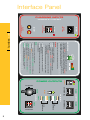
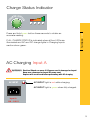
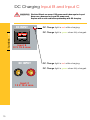
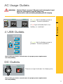
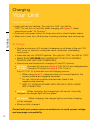
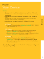
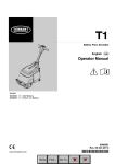
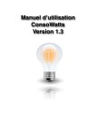
Power your day-to-day when others are power-less. Humless Sentinel User’s Guide www.humless.com User’s Guide humless.com Contents 2 • Safety Instructions page 6 • Meet The Power page 7 • Charging Your Unit page 12 • Powering Your Devices page 13 • Troubleshooting page 14 • Technical Specifications page 15 - About Humless, LLC gives you a seamless solution for challenging power outages. Our technology is so advanced that we have no real competitors. There may be other generators available, but none can offer you all of the following: Safe: humless.com Humless No emissions – none. No dangerous risks unlike fossil fuels and toxic lead-acid batteries (if you can’t throw it away in your family’s garbage can, it’s not good for your family). Silent: No more loud, continuous, sanity-challenging generator noises. Affordable: The next competitor that compares in power, 1000 watts continuous, costs 3 times more. Portable: Easily carried by most, weighing in at 40 lbs. (18 kg.) Renewable: Powered and replenished by natural resources such as the sun, wind and water, as well as mechanical devices such as hand cranks. 3 Trademarks Humless products are a trademark of Humless, LLC. Other trademarks, registered trademarks, and product names are the property of their respective owners and are used herein for identification purposes only. Notice of Copyright Humless User’s Guide © March 2012 Humless, LLC. All rights reserved. humless.com Exclusion for Documentation UNLESS SPECIFICALLY AGREED TO IN WRITING, HUMLESS, LLC (“HUMLESS”) (A) MAKES NO WARRANTY AS TO THE ACCURACY, SUFFICIENCY, OR SUITABILITY OF ANY TECHNICAL OF OTHER INFORMATION PROVIDED IN ITS MANUALS OR OTHER DOCUMENTATION. (B) ASSUMES NO RESPONSIBILITY OR LIABILITY FOR LOSSES, DAMAGES, COSTS OR EXPENSES, WHETHER SPECIAL, DIRECT, INDIRECT, CONSEQUENTIAL, OR COINCIDENTAL, WHICH MIGHT ARISE OUT OF THE USE OF SUCH INFORMATION. THE USE OF ANY SUCH INFORMATION WILL BE ENTIRELY AT THE USER’S RISK. (C) REMINDS YOU THAT IF THIS MANUAL IS PRESENTED IN ANY LANGUAGE OTHER THAN ENGLISH, ALTHOUGH STEPS HAVE BEEN TAKEN TO MAINTAIN THE ACCURACY OF THE TRANSLATION, THE ACCURACY CANNOT BE GUARANTEED. APPROVED HUMLESS CONTENT IS CONTAINED WITHIN THE ENGLISH LANGUAGE VERSION WHICH IS POSTED AT WWW.HUMLESS.COM. Date and Revision March 2012 Revision A Product Number HSS50-120W Contact Information Telephone: 1-800-313-4709 Technical Support: [email protected] Sales and Customer Service: [email protected] All other issues: [email protected] Website: http://www.humless.com Mailing address: Humless, LLC 4626 N., 300 W., Suite #350 Provo, Utah 84604 U.S.A. 4 Please feel free to contact us at any time. Symbols and Terms The following symbols are used in this guide: Warnings are conditions and practices that could result in personal injury. CAUTION Cautions are conditions and practices that could result in damage to the unit or other equipment. humless.com WARNING Important Terms The following terms are helpful for you to know and are used in this guide. TERM A AC DC kW LED mA PV VAC VDC W DEFINITION Ampere or Amp Alternating Current Direct Current Kilowatt; one thousand Watts Light Emitting Diode Milliampere; one thousandth of an ampere Photovoltaic Volts AC Volts DC Watts Additional Information You can find additional information about products and service at www.humless.com. 5 Safety Instructions WARNING This Section provides important safety and operating humless.com instructions. CAUTION Check with medical device manufacturer before powering any life-support systems or other medical devices or equipment to insure it is compatible with the power supplied by the Humless Sentinel. See Technical Specifications on page 14 for the Humless Sentinel details. CAUTION Check with tool and/or equipment manufacturer before powering any of their products to insure it is compatible with the power supplied by the Humless Sentinel. See Technical Specifications on page 14 for the Humless Sentinel details. • Before using your unit, read ALL instructions and information in this user’s guide. • Although intended for indoor use, it can be used outdoors if sheltered. DO NOT expose the unit to rain, snow or extreme environments. To reduce risk of fire hazard, DO NOT cover or obstruct fan vents. Provide a minimum of 6 inches of clearance on all sides of the unit; otherwise, overheating could occur. • You may connect as many as 3 DC power sources and 1 AC power source simultaneously. • To reduce risk of electrical shock, disconnect all sources of AC and DC from the unit before attempting any cleaning or maintenance or before working on any circuits connected. SWITCHING OFF ALL POWER DISCHARGE PORTS WILL NOT ELIMINATE RISK. TURN OFF MAIN POWER AND REMOVE RED KEY. • Inspect all power cords before attempting to charge your unit and connecting devices to discharge ports. If cords are frayed, damaged or questionable, DO NOT connect the device to your unit. Doing so increases the risk of fire and electrical shock. Use common sense. • DO NOT use if your unit has been dropped or damaged in any way. If damaged, see ‘Contact Information’ on page 2. • DO NOT attempt to disassemble the unit. There is a high risk of unit damage as well as personal injury. There are NO serviceable parts. 6 • Repairs should ONLY be done by a qualified Humless repair technician. Meet the Power Thank you for your purchase. The pure sine wave AC inverter output makes your unit compatible for use with many of today’s high-tech electronic devices. It also allows appliance motors to operate more efficiently and at cooler temperatures. If you still have any questions, please contact our support team. See Contact Information on page 4. Let’s Get Started humless.com In order to get the most from your unit, be sure to carefully read this user’s guide. It is important to take some time to become familiar with the Safety Instructions on page 6 of this guide before operation. You should have received the following items in your Humless Sentinel kit: 1. Unit with carrying harness 2. Shoulder Strap 3. Zippered stow pack (1) 4. AC wall outlet charging cord 5. Red Key (2) 6. USB Universal cell phone charger 7. USB LED light Red Key for Main Power Things to remember: • When not in use, turn off all power, including switches, and remove key. • Store unit fully charged. 7 AC INPUT Input A 120 - 240 V USER INSTRUCTIONS TO CHARGE GE STAT AR • Insert red key into main power keyhole. Turn right for “ON;” turn left for “OFF.” Before charging Input C, turn red key to “OFF.” Read instructions under “To Charge.” • Push and hold green Charge Status button for three seconds to check battery status. • Provide a minimum of 6 inches of clearance on all sides of the unit. DO NOT cover or obstruct cooling fan vents; otherwise, overheating could occur. • Make sure voltage and amperage of input and output sources are compatible with unit. • When not in use, turn off all power, including switches, and remove key. US DC INPUT Instructions are the same for charging AC and DC options: • AC Input: Connect AC plug into Input A (120-240 V) and wall or generator. • DC Input: Connect DC plug into Input B (12V 16 A) or Input C (12V 10 A) and also into the charging source. When using Input C, make sure that you connect leads to the correct positive and negative terminals. On unit, red is the positive-side terminal; black is the negative-side terminal. Do NOT turn on main power until leads are properly connected. • AC Input: When charging, the charger light will be red. Once fully charged, the charger light will turn green. • DC Input s: When charging, the charger light is red when charging or fully charged. • Store unit fully charged. Switch 1 Outlet A AC OUTPUTS Outlet B Outlet H 2.1 A Tablets / Pads 1A Cell Phones 120 V 1000 W max. DC OUTPUTS Outlet F Outlet E Outlet D Outlet C USB OUTPUTS 120 V 1000 W max. Switch 2 Outlet G O ER UT 12 V 25 A max. TO USE POW Input B 12 V 16 A max. DC INPUT Consult with your appliance manufacturer to verify proper voltage and amperage compatibility. POWER OUTPUTS CH Instructions are the same for using AC, USB and DC options: • AC Outputs: Connect AC plug into either Outlet A or Outlet B (120 V 1000 W max) and turn on AC Switch 1. • USB Outputs: If using a tablet, pad or laptop, connect USB plug into either Outlet E or Outlet F (2.1 A) and turn on USB Switch 2. • If using a cell phone or other device, connect USB plug into either Outlet C or Outlet D (1 A) and turn on USB Switch 2. • DC Outputs: Connect DC plug into either Outlet G (12 V, 10 A max.) or Outlet H (12 V, 25 A max.), depending on appliance or device. 8 Input C 12 V 10 A max. humless.com Interface Panel CHARGING INPUTS POWERED BY HUMLESS 12 V 10 A max. T LE GE STAT AR Press and hold green button three seconds to obtain an accurate reading. FULL CHARGE STATUS is indicated when all four LEDs are illuminated and AC and DC charge lights in Charging Inputs section show green. humless.com US CH Charge Status Indicator AC Charging Input A WARNING Electrical Shock can occur if AC power cord is damaged or frayed. Never use a damaged or frayed AC power cord. Replace with a new cord before proceeding with AC charging. AC INPUT AC INPUT light is red while charging. AC INPUT light is green when fully charged. Input A 120 - 240 V 9 DC Charging Input B and Input C WARNING Electrical Shock can occur if DC power cord is damaged or frayed. Never use a damaged or frayed DC power cord. Replace with a new cord before proceeding with DC charging. humless.com DC INPUT DC Charge light is red while charging. DC Charge light is green when fully charged. Input B 12 V 16 A max. DC INPUT DC Charge light is red while charging. DC Charge light is green when fully charged. Input C 12 V 10 A max. 10 AC Usage Outlets Electrical Shock can occur if AC power cord is damaged or frayed. Never use a damaged or frayed AC power cord. Replace with a new cord before proceeding with AC charging. Outlet A AC OUTPUTS Switch 1 120 V 1000 W max. Outlet B 120 V 1000 W max. A green light indicates power is present - normal operation. A red light indicates fault, low battery, or overload. 4 USB Outlets humless.com WARNING USB OUTPUTS Outlet C A green light indicates power is present - normal operation. Outlet D Switch 2 Outlet E Outlet F Check with your device manufacturer for proper power requirements and compatibility. DC Outlets DC OUTPUTS Outlet H 12 V 25 A max. POW O ER UT T LE 12 V 10 A max. Outlet G ? There is no light indicator for these ports. Check with your device manufacturer for proper power requirements and compatibility. 11 Charging Your Unit humless.com User Instructions • Insert red key into keyhole. Turn right for “ON;” turn left for “OFF.” Do not turn on unit first when charging with Input C. Read instructions under “To Charge.” • Push and hold green button for three seconds to check battery status. • When not in use, turn off all power, including switches, and remove key. To Charge • Provide a minimum of 6 inches of clearance on all sides of the unit. DO NOT cover or obstruct cooling fan vents; otherwise, overheating could occur. • Insert red key into ON/OFF keyhole. Turn right for “ON;” turn left for “OFF.” • MAKE SURE VOLTAGE AND AMPERAGE OF BOTH CHARGING SOURCE AND UNIT ARE COMPATIBLE. • Instructions are the same for charging AC and DC options: • AC Input: Connect AC plug into Input A (120-240 V) and wall/generator. • DC Input: Connect DC plug into Input B (12V 16 A) or Input C (12V 10 A) and also into the charging source. m When using Input C, make sure that you connect leads to the correct positive and negative terminals. m On unit, red is the positive-side terminal; black is the negative-side terminal. m WAIT TO TURN ON POWER WITH RED KEY UNTIL LEADS ARE CONNECTED. • AC Input: When charging, the charger light will be red. Once fully charged, the charger light will turn green. • DC Inputs: When charging, the charger light is red when charging or fully charged. • Store unit fully charged. Consult with your power source manufacturer to verify proper voltage and amperage compatibility. 12 Power Your Device • Provide a minimum of 6 inches of clearance on all sides of the unit. DO NOT cover or obstruct cooling fan vents; otherwise, overheating could occur. • Insert red key into ON/OFF keyhole. Turn right for “ON;” turn left for “OFF.” • MAKE SURE VOLTAGE AND AMPERAGE OF BOTH CHARGING SOURCE AND UNIT ARE COMPATIBLE. • Instructions are the same for using AC, USB and DC options: AC Outputs: •Connect AC plug into either Outlet A or Outlet B (120 V 1000 W max) and turn on AC Switch 1. humless.com To Use USB Outputs: •If using a tablet, pad or laptop, connect USB plug into either Outlet C or Outlet D (2.1 A) and turn on USB Switch 2. •If using a cell phone or other device, connect USB plug into either Outlet E or Outlet F (1 A) and turn on USB Switch 2. DC Outputs: •Connect DC plug into either Outlet G (12 V, 10 A max.) or Outlet H (12 V, 25 A max.), depending on appliance or device. •When not in use, turn either Switch 1 or Switch 2 off and turn the red key to the left. Consult with your appliance manufacturer to verify proper voltage and amperage compatibility. 13 Troubleshooting humless.com Your Unit 1.The Charge Status Indicator won’t light up when I push the green button. • Make sure red key is inserted into the Main Power keyhole and it is turned to the “ON” position. • Battery is below cutoff voltage – charge battery. 2. The red light above Switch 1 on the 120V AC Outlet lights up and there is no power from outlet. • Battery is low. Check charge state and recharge battery. • Load is too high. Turn down appliance or make sure appliance power ratings are less than 1000W. • Inverter overheating. Create space around vents and allow inverter fan to cool the inverter. 3.The Charge Status Indicator lights give different readings at different times without charging or using any stored power. • Charge Status Indicator provides approximate charge status only. • Battery pack voltage will settle after charging. 4. DC Input charging light will not light up, even though my charging source is plugged in. • Make sure red key is inserted into the Main Power keyhole and it is turned to the “ON” position. • Input polarity is reversed. Reverse input polarity. • Charging source voltage is less than your battery voltage – try a different charging source. 5. 12V DC Outlet won’t work. • Make sure red key is inserted into the Main Power Switch and it is turned to the “ON” position. • Battery is below cutoff voltage – charge battery. 14 Internal Lithium Battery Pack: Voltage: 12.8V Capacity: 50Ah (600Wh) Cycle life: 2,000+ cycles Minimum charge time: < 2.5 hrs Charge retention: >12 months Internal Inverter: Output: 120V AC Pure Sine Wave 1000W Continuous 2000W Peak Integrated AC Charger Output: PWM 14.6V DC 5.0A Charging cycles: CC-CV Charge time 2.5 hrs. Integrated Charge Controller/BMS: Input current: 15.0A Output current: 10.0A Low voltage cutoff: 10.5V High voltage cutoff: 15.0V Outputs: (2) 120V AC (1000W/2000W Continuous/Peak) (2) USB Outlets 5V DC @ 2100 mA Max (2) USB Outlets 5V DC @ 1000 mA Max (2) 12V DC @ 10A Max (120W) - + Product Specifications: Dimensions (L x W x H): 18” x 10” x 12” Weight: 40 lbs. humless.com Technical Specifications 15 HUMLESS 4626 North 300 West Suite #350 Provo, Utah 84604 U.S.A. Tel: 1-800-313-4709 International Tel: +1 801-762-6006 Fax: +1 801-224-7482 www.humless.com