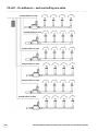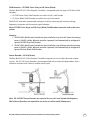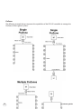
1
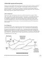
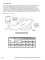
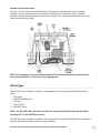
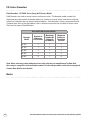
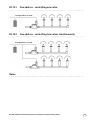
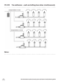
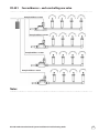
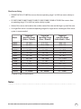
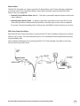
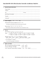
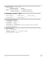
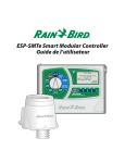
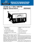
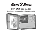
ESP-LXD 2-Wire Decoder Control System Installation & Troubleshooting Guide Contents 2-Wire Decoder System Overview. . . . . . . . . . . . . . . . . . . . . . . . . . . . . . . . . . . . . . . . . . . . . . . 3 Advantages of a 2-Wire Decoder System. . . . . . . . . . . . . . . . . . . . . . . . . . . . . . . . . . . . . . . 4 2-Wire Path Layout and Connections. . . . . . . . . . . . . . . . . . . . . . . . . . . . . . . . . . . . . . . . . . . 5 Valve Types. . . . . . . . . . . . . . . . . . . . . . . . . . . . . . . . . . . . . . . . . . . . . . . . . . . . . . . . . . . . . . . . . . . . . . . 7 ESP-LXD 2-Wire Decoder Controller . . . . . . . . . . . . . . . . . . . . . . . . . . . . . . . . . . . . . . . . . . . . 8 ESP-LXD Controller Option Cartridges. . . . . . . . . . . . . . . . . . . . . . . . . . . . . . . . . . . . . . . . . . 8 Rain Bird LIMR Controller Remote . . . . . . . . . . . . . . . . . . . . . . . . . . . . . . . . . . . . . . . . . . . . . . 9 ESP-LXD Control System Flow & Weather Sensors. . . . . . . . . . . . . . . . . . . . . . . . . . . . . 9 Rain Bird Weather Sensors. . . . . . . . . . . . . . . . . . . . . . . . . . . . . . . . . . . . . . . . . . . . . . . . . . . . . 10 Rain Bird ESP-LXD Series Controller Enclosures. . . . . . . . . . . . . . . . . . . . . . . . . . . . . . 11 FD-Series Decoders. . . . . . . . . . . . . . . . . . . . . . . . . . . . . . . . . . . . . . . . . . . . . . . . . . . . . . . . . . . . 12 2-Wire Cable & Splices. . . . . . . . . . . . . . . . . . . . . . . . . . . . . . . . . . . . . . . . . . . . . . . . . . . . . . . . . .18 Grounding & Surge Protection. . . . . . . . . . . . . . . . . . . . . . . . . . . . . . . . . . . . . . . . . . . . . . . . 19 Flow & Station Management. . . . . . . . . . . . . . . . . . . . . . . . . . . . . . . . . . . . . . . . . . . . . . . . . . 21 Rain Bird ESP-LXD 2-Wire Decoder Controller Installation Checklist. . . . . . . . 26 ESP-LXD 2-Wire Decoder Control System Diagnostics. . . . . . . . . . . . . . . . . . . . . . . 28 ESP-LXD 2-Wire Decoder Control System Troubleshooting . . . . . . . . . . . . . . . . . 31 Rain Bird Global Support Plan (GSP) ESP-LXD Controller purchase includes a 6-month GSP Phone Support Plan. Contact GSP at 877-351-6588 (U.S. and Canada) for support. Ask about free pre-construction training to get your crew up to speed and avoid common pitfalls. Rain Bird Spec Hotline Please call the Rain Bird Spec Hotline number at 800-458-3005 (U.S. and Canada) for assistance with specifying an ESP-LXD 2-Wire Decoder System. You may also send an email with questions to: [email protected] For information contained in this guide related to troubleshooting, please contact GSP support (see above). Specifications Tools Specification tools including CAD Details and Written Specifications for the Rain Bird ESP-LXD Series 2-Wire Control System can be found at www.rainbird.com/esplxseries Copyright © 2013 Rain Bird Corporation. All rights reserved. No part of these materials may be reproduced by any means, nor translated into machine language, without written permission of the publisher. Rain Bird®, ET Manager™, IQ Central Control System™, FloWatch™, FloManager™, FloZone™, and SimulStations™ are trademarks of the Rain Bird Corporation. All rights reserved. 2 ESP-LXD 2-Wire Decoder Control System Installation & Troubleshooting Guide 2-Wire Decoder System Overview A Rain Bird ESP-LXD 2-Wire Decoder Control System provides modular control of small to large irrigation systems. Unlike traditionally-wired controllers that power the valve solenoids directly through individual valve wires, a 2-wire decoder controller uses a 2-wire cable to interconnect decoders that in turn control the valve solenoids. An ESP-LXD controller is programmed similar to a traditional-wired controller. The difference is factory assigned decoder addresses are assigned to stations, master valves, and sensors. As irrigation programs execute, the controller sends commands via the 2-wire path cable to the decoders located at each valve and sensor. The decoders directly activate the solenoids on the valves and monitor the sensors. Typical 2-Wire Decoder to Valve Connections ESP-LXD 2-Wire Decoder Control System Installation & Troubleshooting Guide 3 Advantages of a 2-Wire Decoder System Aesthetics An ESP-LXD 2-Wire Decoder Controller provides transparent automatic control of the irrigation system. There are fewer above ground obstructions, making a 2-wire decoder system ideal for an application in which the environmental elegance of the site is to remain undisturbed. Automatic irrigation control can be installed on a site with fewer above ground enclosures. The higher station capacity of the ESP-LXD controller (up to 200 stations) can replace multiple traditionally-wired controllers (usually a maximum of 48 stations) and required power drops. Designed for Protection from the Elements The field components of a Rain Bird ESP-LXD 2-Wire Decoder System are designed for underground burial, so they are all completely weatherproof. This makes a 2-wire decoder system a perfect application for a site that can be affected by flooding. Anywhere that an automatic control system can be damaged by the elements of nature a 2-wire decoder system can be buried without fear of damage. Vandal Resistant Since all the 2-wire decoders are underground, it is an ideal solution to the problem of vandal damage on an irrigation system. On a site where vandalism is a concern, a 2-wire decoder system allows all of the field components to be put underground and out of sight in potentially lockable valve boxes, therefore, out of the reach of vandals. A single 2-wire cable can replace as many as 200 individual wires in a traditionally-wired control system making it a much lower target for copper wire thefts. Flexible Installation and Simple Expansion A Rain Bird ESP-LXD 2-Wire Decoder Controller System controls the field decoders through a 2-wire path interconnecting the controller and all the decoders. This 2-wire path carries both the communication and power to operate the decoders and the irrigation valves. 2-wire decoders can be added to the field in any type of layout desired. This flexible installation simplifies the installation process, and also allows the installation to be done in multiple phases. When additional areas are being prepared for irrigation, they can be connected to the rest of the system simply by splicing into the two-wire path on the existing layout. If a valve needs to be added simply wire the new valve to a 2-wire decoder, wire the decoder to the existing 2-wire path, and program the address for this decoder into the controller. This provides for simple expansion or changes to the decoder system in the future. 4 ESP-LXD 2-Wire Decoder Control System Installation & Troubleshooting Guide 2-Wire Path Layout and Connections The design of a Rain Bird ESP-LXD 2-Wire Decoder Controller system requires careful consideration to the layout of the decoders on the 2-Wire path. Since a decoder system powers the electric solenoids through the 2-wire path, the 2-wire path must be able to provide enough voltage to power the solenoids. There are design specifications limiting the length of the 2-wire Critical Path. Refer to page eight of this guide for design specifications. 2-Wire Configurations There are two types of configurations that can be used for the layout of 2-wire paths: STAR or LOOP. The controller will supply up to four separate 2-wire paths for a STAR configuration and up to two separate 2-wire paths for LOOP configurations. Depending upon the design of the site, it is preferable to separate the 2-wire paths into multiple wire runs rather than install a single 2-wire path throughout the site. These wire paths can be configured in either the STAR or LOOP layout or a combination of the two types. For ease of troubleshooting, the STAR configuration is recommended. Star Configuration For normal installations with 2-wire path runs that are not excessively long, the recommended layout for the 2-wire path is the STAR configuration. This is to facilitate ease of troubleshooting the system should it experience a wire fault or short. The distance of the farthest decoder from controller measured along the 2-wire path is considered the Critical Path of the 2-wire cable for a STAR configuration. The maximum distance for the Critical Path is 1.65 miles for 14 AWG Maxi Cable, and 2.63 miles for 12 AWG Maxi Cable. For metric cable the maximum distance for the Critical Path is 3.0 Kilometers for 2.5 mm² cable. 2-Wire Path Star Pattern Design ESP-LXD 2-Wire Decoder Control System Installation & Troubleshooting Guide 5 Loop Configuration If the installation requires longer wire runs than are possible with the STAR configuration (farther than 1.65 miles away from the controller) then a LOOP configuration may be used. A LOOP configuration requires looping the 2-wire path out to the farthest decoder then back to the controller. In a LOOP configuration, the Critical Path is the distance measured by following the 2-wire path around the loop out to the farthest decoder and back to the controller. The maximum distance for the Critical Path for a LOOP configuration is 6.61 miles for 14 AWG Maxi Cable and 10.52 miles for 12 AWG Maxi Cable. For metric cable the maximum distance for the Critical Path is 12.0 Kilometers for 2.5 mm² cable. 2-Wire Path Loop Pattern Design Nominal Wire Size 6 Maximum Critical Path Lengths for 2-Wire Paths Max. Length For Critical Path Ohms per 1000' or Star Loop Ohms per Km (per conductor) Km Miles Km Miles 2.5 mm2 7.5 0hms/Km 3.00 1.86 12.00 7.46 14 AWG 2.58 0hms/1000' 2.66 1.65 10.63 6.61 12 AWG 1.62 0hms/1000' 4.23 2.63 16.93 10.52 ESP-LXD 2-Wire Decoder Control System Installation & Troubleshooting Guide Decoder to Solenoid Layout All valves must be connected to field decoders for irrigation management by the controller. Decoders must be wired both to a valve and by splicing to the 2-wire path. Splices and field decoders should always be placed in valve boxes (except when valve-in-head sprinklers are used, which can be directly buried). NOTE: For secondary wire run, the distance between the field decoder and the solenoid (valve) can not exceed 450 feet (137 meters) using 14 gauge wire. Valve Types The ESP-LXD 2-Wire Decoder Controller is compatible with the following Rain Bird Commercial Valves: PGA Series PEB/PESB/PESBR Series GB Series EFB-CP Series BPE/BPES Series NOTE: The ESP-LXD 2-Wire Decoder Controller will not work with Rain Bird Residential Valves including DV, JTV, HV, ASVF Series Valves. The ESP-LXD 2-Wire Decoder Controller is also compatible with Rain Bird Golf Valve-in-Head Rotors and Rain Bird Commercial PSR-Series Pump Start Relays. ESP-LXD 2-Wire Decoder Control System Installation & Troubleshooting Guide 7 ESP-LXD 2-Wire Decoder Controller ESP-LXD 2-Wire Decoder Controller The ESP-LXD has a standard capacity of 50 stations and is expandable to 125 or 200 stations increments using the ESPLXD-SM75 75-station modules. ESPLXD-M50 2-Wire Decoder Module Included with every ESP-LXD is the ESPLXD-M50 2-Wire Decoder and Flow Smart Module, a “doublewide” module which snaps onto two adjacent mounts on the controller backplane. The ESPLXD-M50 Module includes the lugs for attachment of the two-wire path cables. FloWatch™ logs flow and quickly identifies and isolates high or low flow situations, such as mainline breaks. Manages up to five (5) Points of Connection each through separate or combined Master Valves and FloZones – See Appendix for various configurations. FloManager™ Manages flow demand and ensures you don’t overtax your water supply. Finds combinations of stations to operate simultaneously to use all available capacity from the water supply. ESPLXD-SM75 75-Station Expansion Module Adds an additional 75 stations in the ESP-LXD and snaps onto the controller backplane. One ESPLXD-SM75 module increases the station capacity to 125 stations and two increases the station capacity to 200 stations. ESP-LXD Controller Option Cartridges PBC-LXD Programming Backup Cartridge Backup and restore programming for up to eight ESP-LXD Decoder Controllers. Option: Attach a barcode scanning pen (sold separately) and scan the peel-off barcode labels from the Programming Chart included with the controller. Your decoder addresses are entered for you automatically saving you time. MS100-2 Barcode Scanning Pen - Unitech www.ute.com ETC-LX ET Manager™ Cartridge The Rain Bird ET Manager Cartridge easily upgrades the ESP-LXD Controller to an ET/Weather-based irrigation smart controller. Available in most part of North America only, and requires a signal provider for your geographic area. IQ Central Control Compatible Through the incorporation of an IQ-NCC Communication Cartridge, the ESP-LXD controller can be controlled from the Rain Bird IQ™ Central Control System. Communication options: -GP GPRS/ Cellular, -PH Phone, -EN Ethernet, -WF Wi-Fi, and -RS RS-232 (RS-232 used for Radio or Direct Connect) 8 ESP-LXD 2-Wire Decoder Control System Installation & Troubleshooting Guide Rain Bird LIMR Controller Remote LIMR-KIT 900MHz Transmitter, Receiver, Quick-Connects, Carrying Case LIMR-TX 900MHz Transmitter Only LIMR-QC603 6-Pin Quick Connect Cable, 3 feet LIMR-QC630 6-Pin Quick Connect Cable, 30 feet LIMR-RX 900MHz Receiver Only ESP-LXD Control System Flow & Weather Sensors Flow Sensors Up to five (5) flow sensors can be installed on the 2-Wire path. SD-210 Sensor Decoder are required for each sensor. Rain Bird FS-Series Flow Sensors are available in ½” to 4” PVC Tee, 1” to 2” Brass Tee, and Brass and Stainless Steel Insert Style models. Rain Bird FS-Series Flow Sensors FS050P ½” Slip x Slip, PVC Tee Flow Sensor FS400P 4” Slip x Slip, PVC Tee Flow Sensor FS075P ¾” Slip x Slip, PVC Tee Flow Sensor FS100B 1” Threaded, Brass Tee Flow Sensor FS100P 1” Slip x Slip, PVC Tee Flow Sensor FS150B 1-½” Threaded, Brass Tee Flow Sensor FS150P 1-½” Slip x Slip, PVC Tee Flow Sensor FS200B 2” Threaded, Brass Tee Flow Sensor FS200P 2” Slip x Slip, PVC Tee Flow Sensor FS350B Brass Insert (for Pipe Saddle) Flow Sensor for 3” to 12” Pipe Diameters FS300P 3” Slip x Slip, PVC Tee Flow Sensor Pipe Inside Diameter entry required ESP-LXD 2-Wire Decoder Control System Installation & Troubleshooting Guide FS350SS Stainless Steel Insert (for Pipe Saddle) Flow Sensor for 3” to 12” Pipe Diameters Pipe Inside Diameter entry required Custom 3rd-party flow sensor or meter K-Factor and Offset entry required (supplied by 3rd-party manufacturer) Reed-Switch 2-wire output only with minimum 2 pulses per 10 seconds for the lowest station flow rate 9 Rain Bird Weather Sensors One locally wired (to the decoder module) and up to 3 installed on the 2-wire path. SD-210 Sensor Decoder required for each 2-wire path weather sensor. Notes: 1. Operates only with switch-type normally closed sensors. 2. Not compatible with tipping rain-can sensors. 3. Compatible with Rain Bird Anemometer Wind Speed Sensor when used with a Rain Bird PT-3002 Pulse Transmitter. RSDBEX Wired Rain Shutoff Sensor, Bracket Mount Configure as Rain Sensor RSDCEX Wired Rain Shutoff Sensor, Conduit Mount Configure as Rain Sensor WR2RC Wireless Rain Shutoff Sensor Configure as Rain Sensor WR2RFC Wireless Rain/Freeze Shutoff Sensor Configure as Rain/Freeze Sensor ANEMOMETER Wind Speed Sensor (WSS) Requires Rain Bird PT3002 Pulse Monitor Configure as Wind Sensor WS1 Soil Moisture Sensor (SMS) Irrometer Water Switch - www.irrometer.com Configure as Soil Moisture Sensor Custom Prevent Normally-closed sensor that prevents station operation when sensor circuit opens Custom Pause Normally-closed sensor that pauses station operation when sensor circuit opens 10 ESP-LXD 2-Wire Decoder Control System Installation & Troubleshooting Guide Rain Bird ESP-LXD Series Controller Enclosures The ESP-LXD Series 2-Wire Decoder Controller standard enclosure is a NEMA 3R rated, plastic, locking, wall-mount enclosure. Optional painted metal and Stainless Steel enclosures include: LXMM Painted metal, locking, wall-mount enclosure, NEMA 3R LXMM-PED Painted metal, locking pedestal for LXMM enclosure, NEMA 3R LXMM-SS Stainless Steel, locking, wall-mount enclosure, NEMA 3R LXMM-PEDSS Stainless Steel, locking pedestal for LXMM-SS enclosure, NEMA 3R Metal Cabinet & Pedestal The ESP-LXD controller standard plastic case field installs into the LXMM or LXMM-SS enclosure for wall-mount applications. Add the LXMM-PED or LXMM-PEDSS pedestal for free-standing controller applications. ESP-LXD 2-Wire Decoder Control System Installation & Troubleshooting Guide 11 FD-Series Decoders Field Decoders - FD-TURF Series (Grey) & FD-Series (Black) Field Decoders are used to control station and master valves. The decoder model number first digit represents the number of decoder addresses (stations or master valves) and the last digit the quantity of solenoids that can be activated per address. Each decoder is factory programmed with a unique three, four or five digit address that is utilized to associate with a station or master valve. There are five types of field decoders: Rain Bird Field Decoder Models Number of Addresses Per Decoder Maximum Number Of Solenoids Per Address Maximum Addresses Operating At Once FD-101 1 1 1 FD-102 1 2 1 FD-202 2 2 2 FD-401 4 1 4 FD-601 6 1 6 Decoder Model Note: When activating valves and pump start relays that are not manufactured by Rain Bird, there may be exceptions to the maximum number of solenoids per address that can be energized. Contact Rain Bird for more details.. Notes: 12 ESP-LXD 2-Wire Decoder Control System Installation & Troubleshooting Guide FD-101 One address – controlling one valve Example Address # 12345 FD-102 One address – controlling two valves simultaneously Example Address # 12346 Notes: ESP-LXD 2-Wire Decoder Control System Installation & Troubleshooting Guide 13 FD-202 Two addresses – each controlling two valves simultaneously Example Address # 12347 Example Address # 12348 Notes: 14 ESP-LXD 2-Wire Decoder Control System Installation & Troubleshooting Guide FD-401 Four addresses – each controlling one valve Example Address # 12349 Example Address # 12350 Example Address # 12351 Example Address # 12352 Notes: ESP-LXD 2-Wire Decoder Control System Installation & Troubleshooting Guide 15 FD-601 – Six addresses – each controlling one valve Example Address # 12360 Example Address # 12361 Example Address # 12362 Example Address # 12363 Example Address # 12364 Example Address # 12365 16 ESP-LXD 2-Wire Decoder Control System Installation & Troubleshooting Guide Field Decoders – FD-TURF-Series (Grey) or FD-Series (Black) The Rain Bird ESP-LXD 2-Wire Decoder Controller is compatible with two types of FD Series Field Decoders. FD-TURF Series (Grey) Field Decoders are sold in the U.S. and Canada. FD Series (Black) Field Decoders are sold in the rest of the world. The ESP-LXD controller automatically configures itself, by measuring the incoming voltage frequency, to operate with the correct type of decoder. Note: FD-TURF Series (Grey) and FD-Series (Black) Field Decoders cannot be used on the same system. Examples: 1. The ESP-LXD 2-Wire Decoder Controller has been installed at a site in the U.S. where the incoming power is 120 VAC @ 60 Hz. When the controller is powered, it will automatically be configured to operate FD-TURF (Grey) Field Decoders. 2. The ESP-LXD 2-Wire Decoder Controller has been installed at a site in Europe where the incoming power is 230 VAC @ 50 Hz. When the controller is powered, it will automatically be configured to operate FD-Series (Black) Field Decoders. Sensor Decoder – SD-210 (Green) The Rain Bird ESP-LXD 2-Wire Decoder Controller integrates the use of select flow and weather sensors. The SD-210 Sensor Decoder is pre-programmed with a unique five digit address that is utilized to associate with a flow or weather sensor input. Note: SD-210TURF Sensor Decoders are required for use in U.S. and Canada (60 Hz power). SD210 Sensor Decoders are required for use in the rest of the world (50 Hz power). ESP-LXD 2-Wire Decoder Control System Installation & Troubleshooting Guide 17 Lightning Surge Protector – LSP-1 (Yellow) The ESP-LXD controller and the 2-wire path must be properly surge protected and grounded. Doing so can help prevent damage to the controller and irrigation system and also significantly reduce troubleshooting, repair time and expense. Failure to do so could result in failure of your controller and voiding the warranty. Refer to page 24 of this guide for recommended location and quantity of LSP-1 Lightning Surge Protectors. 2-Wire Cable & Splices MAXI Cable Use only MAXI Cable for 2-Wire path applications. Construction: Special irrigation control wire Conductor: Tin coated, soft drawn bare copper (ASTM Spec. 33) Two (2) conductors Solid (14awg and 12 awg) Insulation: Polyvinyl Chloride (PVC) Outer Jacket: Polyethylene (PE) Colors: Red, White, Black, Orange, Blue, Yellow, Purple, Brown, Pink, Grey, & Green Temperature:60°C Voltage: 18 600 volts ESP-LXD 2-Wire Decoder Control System Installation & Troubleshooting Guide Wire Splices Use only 3M DBR/Y-6 splice kits for all electrical wiring connections to the 2-wire path. Improper wiring can cause serious damage to your controller or irrigation system. Grounding & Surge Protection The ESP-LXD 2-Wire Decoder Controller and the 2-wire path must be properly surge protected and grounded. Doing so can help prevent damage to the controller and irrigation system and also significantly reduce troubleshooting, repair time and expense. Failure to do so could result in failure of your controller and voiding the warranty. To comply with proper installation specifications, the following components should be grounded: ESP-LXD 2-Wire Decoder Controller ESPLXD-M50 2-Wire Decoder Module LSP-1 Lightning Surge Protector SD-210 Sensor Decoder FD-401 Field Decoder FD-601 Field Decoder Notes: 1. Each installed grounding system shall maintain a maximum ground resistance of 10 ohms, or less. 2. Refer to the Rain Bird Grounding Recommendations document for proper specifications on Grounding System Installation and Grounding System Design. ESP-LXD 2-Wire Decoder Controller TThe ESP-LXD 2-Wire Decoder Controller is protected against electrical surges through the ground provided by the primary ground of the incoming power to the controller. ESPLXD-M50 2-Wire Decoder Module The ESPLXD-M50 2-Wire Decoder Module provides a ground lug on the front of the module that accepts a #6 AWG Bare Copper Wire that is connected to a ground rod or plate. A grounding wire on the module should be connected to the ground (GND) spade connector on the small terminal strip above the transformer. It is not necessary to connect this ground lug to an earth ground. ESP-LXD 2-Wire Decoder Control System Installation & Troubleshooting Guide 19 LSP-1 Line Surge Protector The LSP-1 Line Surge Protector provides surge protection for the ESP-LXD controller and the 2-wire path and should be spliced into the 2-wire path in three distinct areas: 1. ESP-LXD 2-Wire Decoder Controller – The LSP-1 Line Surge Protector provides surge protection for the ESP-LXD controller against electrical surges originating from each 2-Wire Path utilized. The LSP-1 Line Surge Protector shall be spliced into each 2-Wire Path in close proximity to the ESP-LXD controller. 2. 2-Wire Path – The LSP-1 Line Surge Protector provides surge protection for the following FD-Series Field Decoders installed on the 2-Wire Path: FD-101 FD-102 FD-202 Note: The 2-wire path shall be surge protected and grounded with one LSP-1 Line Surge Protector every 500 feet or every 8 decoders, whichever is smaller. 3. Termination of 2-Wire Path – An LSP-1 Line Surge Protector shall be installed at the end of the 2-wire path in a STAR configuration. SD-210 Sensor Decoder SD-210 Sensor Decoders have a built-in line surge protector to provide surge protection for each sensor installed on the 2-Wire path. FD-401 and FD-601 Field Decoder The FD-401 and FD-601 Field Decoders have a built-in line surge protector to provide surge protection for Field Decoders installed on the 2-Wire Path: FD-101 FD-102 FD-202 Note: Because the FD-401 & FD-601 Field Decoders and SD-210 Sensor Decoder have built-in surge protection, the 2-wire path surge protection requirement could be stated in the following manner: The 2-wire path shall be surge protected and grounded with one LSP-1, FD-401, FD-601 or SD-210 every 500 feet or every 8 decoders, whichever is smaller. 20 ESP-LXD 2-Wire Decoder Control System Installation & Troubleshooting Guide Flow & Station Management The ESP-LXD 2-Wire Decoder Controller can manage up to five (5) water points of connection, five (5) Master Valves, and five (5) FloZones through a variety of hydraulic configurations using the following concepts and/or features: Master Valve – A valve or pump start relay that controls (turns on/off ) a point of connection where the irrigation system connects to the water supply. Flow Sensor – Used to monitor the irrigation system real-time flow rate. The current system flow rate is displayed at the controller and totalized in a flow log. The flow rate is used to detect high or low flow conditions and diagnose and shutdown the problem valve or water source and issue alarms. FloZone – A group of stations that receive water from one or more points of connection. Each water source would have its own Master Valve and Flow Sensor. If a mainline receives water from two or more points of connection the controller combines the input from all associated flow sensors to determine the FloZone real-time flow rate. There are two primary Flow Management features: FloManager (available on ESP-LXD and ESP-LXD models)– Manages the total system flow rate by dynamically selecting one or more stations that operate simultaneously to use the full capacity of the water source. Operating the irrigation system at peak flow capacity shortens the overall time it takes to irrigate the site and reduces pumping power costs FloWatch (available on ESP-LXD models only) – Monitors and logs the real-time system rate with a flow sensor. A Learn Flow Utility learns and records the nominal flow rate of each station. If a high or low flow condition is detected, the controller will follow user configured steps to diagnose and eliminate the problem (problem station valve or water source is quarantined). SimulStations™ The ESP-LXD can operate multiple programs and stations concurrently. The controller ensures sufficient power is available to operate a maximum of eight (8) valve solenoids simultaneously. The range of SimulStations available per program (ABCD) is one (1) through eight (8) The range of SimulStations available for the entire ESP-LXD controller is one (1) through (8) for irrigation and non-irrigation stations. Each normally closed master valve that needs to be open for irrigation to occur reduces the maximum SimulStation by 1. Example: The system has one (1) normally closed master valve. The maximum number of SimulStations is reduced from eight (8) to seven (7). ESP-LXD 2-Wire Decoder Control System Installation & Troubleshooting Guide 21 FloZones The following example designs represent the capabilities of the ESP-LXD controller to manage the FloZones of the irrigation system: 22 ESP-LXD 2-Wire Decoder Control System Installation & Troubleshooting Guide Flow Sensor Sizing FS050P, FS075P, & FS100P flow sensors have an operating range 2 to 20 ft/sec (water velocity in pipe). FS150P, FS200P, FS300P, FS400P, FS100B, FS150B, FS200B, FS350B & FS350SS flow sensors have an operating range 1/2 to 30 ft/sec (water velocity in pipe). Select a flow sensor size based on the smallest station flow rate and the largest system flow rate. If a single flow sensor is outside the operating range of a single sensor a dual bypass flow sensor system is recommended. Model Suggested Operating Range (Gallons / Minute) Suggested Operating Range (Liters / Minute) Suggested Operating Range (Cubic Meters / Hour) FS050P FS075P FS100P FS150P FS200P FS300P FS400P FS100B FS150B FS200B FS350B FS350SS 1.9 - 18.9 3.3 - 33.2 5.4 - 53.9 5 - 100 10 - 200 20 - 300 40 - 500 2 - 40 2 - 82.6 4.9 - 294 12 - 45000* 12 - 45000* 7.2 - 71.7 12.6 - 125.8 20.4 - 204 18 - 378 36 - 756 78 - 1134 150 - 1890 6 - 150 6.3 - 313 18.5 - 1112 48 - 168000* 48 - 168000* 0.43 - 4.3 0.75 - 7.5 1.2 - 12.2 1.1 - 22.7 2.3 - 45.4 4.5 - 68.1 9.1 - 113.6 0.5 - 9 0.4 - 18.7 1.1 - 66.7 2.7 - 10200* 2.7 - 10200* * Depends on pipe size and material Notes: ESP-LXD 2-Wire Decoder Control System Installation & Troubleshooting Guide 23 Flow Sensor Installation Sensor to be placed in straight run (sensor run) of pipe. A sensor run of no less than 10 times the pipe diameter on the sensor inlet is required. A sensor run of no less than 5 times the pipe diameter on the sensor outlet is required. The associated master valve would typically be installed on the upstream side before the sensor run. Low Flow Bypass Design A Low Flow Bypass design is where two (2) flow sensors are utilized to accurately measure both low & high flow rates on a single water source. The larger master valve’s pressure regulator is set three (3) to five (5) lbs. lower than the pressure regulator on the smaller master valve. Low flows will automatically flow through the small master valve and flow sensor until the flow rate increases to the point where the three (3) to five (5) PSI differential is overcome and flow will automatically flow through both master valves and flow sensors. Configure both master valves and flow sensors on the same FloZone. 24 MV FS200P MV FS100B ESP-LXD 2-Wire Decoder Control System Installation & Troubleshooting Guide Master Valves The ESP-LXD Controller can support up to five (5) Master Valves via FD-Series Decoders configured as a Master Valve. Each is programmable by station. Both Normally-Closed and Normally-Open Master Valves are supported. Normally-Closed Master Valve (default) – The valve is powered to open and opens each time a station operates. Normally-Open Master Valve – A specialty valve that is powered to close and will only close when a flow problem is detected by the controller. Normally-open master valves are popular for systems with quick coupling valves making water available for manual watering at any time. PSR-Series Pump Start Relays Rain Bird PSR-Series Pump Start Relays can be used with FD-Series Decoders configured as a Master Valve to start a pump. For more information go to: www.rainbird.com/landscape/products/pumps/ PumpStartRelays.htm See installation detail below for connecting the ESP-LXD 2-Wire Decoder Controller to the Pump Start on the Pump Station Panel. ESP-LXD 2-Wire Decoder Control System Installation & Troubleshooting Guide 25 Rain Bird ESP-LXD 2-Wire Decoder Controller Installation Checklist 1. General Project Information Project Name____________________________________________________________________ Location________________________________________________________________________ City______________________________________ County________________________________ Brief Project Description___________________________________________________________ Designer________________________________________________________________________ Contractor______________________________________________________________________ 2. Station Capacity 50* 125 200 ESPLXD-SM75 Expansion Module 0 1 2 * 50 Stations are provided with the ESP-LXD Decoder Controller Master Valves 0 1 2 3 4 5 Note: Quantity of Master Valves and Flow Sensors should be the same. 3. Sensors Flow Sensors ** 0 Types FS050P FS400P 1 2 3 4 5 FS075P FS100P FS150P FS200P FS300P FS100B FS150B FS200B FS350B FS350SS Weather Sensors 0 Types RSD 1 2 3 Remote** Local WR-2 WRF-2 WSS (with PT-3002) SMS ** SD-210 (Green) Quantity _______ ** One SD-210 required per 2-wire sensor 4. Option Cartridges PBC-LXD Programming Backup Cartridge ETC-LX ET Manager™ Cartridge IQ-NCC Network Communication Cartridge 26 Yes No Yes No Yes No Model ______________ ESP-LXD 2-Wire Decoder Control System Installation & Troubleshooting Guide 5. Optional Enclosure Yes No Wall-Mount Enclosure Pedestal Model LXMM Painted Metal LXMM-SS Stainless Steel LXMM-PED Painted Metal LXMM-PEDSS Stainless Steel 6. Field Decoders Grey Turf Black FD-101 Quantity _______ FD-202 Quantity _______ FD-601 Quantity _______ FD-102 Quantity _______ FD-401 Quantity _______ 7. Grounding & Surge Protection Grounding Rod Quantity _______ Grounding Plate Quantity _______ LSP-1 (Yellow) Quantity _______ Notes: Install one LSP-1: 1) per Wire Path from Controller 2) Every 500 feet / 150 meters on Wire Path 3) Termination of each Wire Path. 8. Maxi Cable & Splices Layout Star Branch Maxi Cable – Quantity _______ 14 AWG 12 AWG 3M DBR/Y-6 Splices Kits – Quantity _______ ESP-LXD 2-Wire Decoder Control System Installation & Troubleshooting Guide 27 ESP-LXD 2-Wire Decoder Control System Diagnostics The ESP-LXD Controller includes multiple diagnostic functions to help you troubleshoot and pinpoint the source of a problem. Refer to section C / Systems Diagnostics in the ESP-LXD Controller Installation, Programming & Operation Manual for step-by-step instructions to use the diagnostic features. Tools and equipment An accurate “as-built” showing wire path and decoder locations, the number and type of the decoders on each wire path, and decoder addresses Filled out ESP-LXD Controller Programming Guide with decoder addresses and station/MV/ sensor assignments A Volt/Ohm Meter (multi-meter) capable of reading 0 to 50 volts AC/DC and resistance from 0 to 1,000,000 Ohms A Clamp Meter for measuring AC current with a precision of 1.0 mA (milliamp). Wire tracing and fault finding equipment Spare system components and tools including: spare FD-Series Decoders, SD-210 Sensor Decoders, 3M DBR/Y-6 wire splice kits, wire strippers, DPU-210 Decoder Programming Unit (optional) Calculating the total system mA (milliamp) draw Each single address FD-Series Field Decoder (FD101, FD102) draws 0.5mA Each multi-address FD-Series Field Decoder (FD202, FD401, FD601) draws 1.0 mA Add up the total decoders of each type for each wire path and calculate the wire path mA draw Add the mA for each wire path together for the total system mA draw Types of field wiring issues Broken wire Short circuit Ground fault Notes • A majority of field wiring issues are caused by poor wire splices! Use only 3M DBR/Y-6 Wire Splice Kits. All splices should be made in splice boxes. • If the 2-Wire Path is Looped, disconnect the loop half way out before troubleshooting 28 ESP-LXD 2-Wire Decoder Control System Installation & Troubleshooting Guide Break / open circuit in the 2-wire path cable You will notice one or more stations are not running even though they are programmed to operate. If the system is using flow sensing, you will receive a low (zero) flow alarm for each disconnected decoder station. - Use the Test All Stations to check which stations are operating Controller diagnostics - Turn dial to Test All Stations / Check System; Select 2-Wire Diagnostics - Select Decoder Test - The results will indicate that one of more decoders have an Open Circuit and you will be prompted to Check Wiring; Go the location of the decoder that are not responding and check wire splices 2-Wire Path diagnostics - Check your as-built drawing. If you notice that all the decoders that are not responding are in a single leg of the 2-wire path, the open circuit exists between the last working decoder and the first non-working decoder. Check the splices at that location first. Also look for signs of recent construction/digging between the working and non-working decoders. - Turn the controller dial to 2-Wire Diagnostics; Select Short Finding; Turn Short Finding Mode On. Use a Clamp Meter to measure the Amp Draw of the 2-wire path cable conductors at the last working decoder and the first non-working decoder. Note any discrepancies in the readings. You must know the number and type of each decoder downstream to know what the mA reading up should be reading (see Calculating the total system mA draw section for more information). Short circuit (red and black wires crossed) of the 2-wire path cable The controller alarm light will be illuminated and the alarm will inform you the controller has switched to Short Finding Mode. You must fix the short circuit before the controller will switch back to normal irrigation mode. 2-Wire Path diagnostics - Disconnect each 2-wire path cable one at a time from the controller ESPLXD-M50 Decoder Module until the controller exits Short Finding Mode. Reconnect that 2-wire path cable, and if the Short Finding Mode returns you know the short is on that leg of the 2-wire path. - Refer to the as-built to see the location of the 2-wire path. Walk the route of the 2-wire path cable and check for signs of recent construction/digging. - Find a decoder location about half-way down the 2-wire path cable. Disconnect the splices. See if the controller is still in Short Finding Mode. If the Short Finding Mode has cleared, the problem is downstream of this location. If the controller is still in Short Finding Mode, the problem is between this location and the controller. Keep disconnecting segments of the 2-wire path until you isolate the problem. ESP-LXD 2-Wire Decoder Control System Installation & Troubleshooting Guide 29 - Use a Clamp Meter to measure the Amp Draw of the 2-wire path cable conductors at the last working decoder and the first non-working decoder. Note any discrepancy in the readings. You must know the number and type of each decoder downstream to know what the mA reading up should be reading (see Calculating the total system mA draw section for more information). - The problem may be caused by a decoder or LSP-1 Line Surge Protector damaged by a lightning power surge. The controller will exit Short Finding Mode when this damaged decoder or line surge protector is disconnected from the 2-wire path. Earth ground fault / 2-wire path cable/splice leaking to earth ground A 2-Wire Path Cable conductor is leaking to ground possibly due to a bad wire splice, or a nicked or damaged cable. This issue may come and go depending on the soil moisture level. When the soil is very wet the problem will be worse than when the soil is dry. Controller diagnostics - Turn dial to Test All Stations / Check System; Select 2-Wire Diagnostics - Select Line Survey. Note the Milliamp (mA) reading. The mA reading will be higher than normal when current is leaking to ground. You must know the number and type of each decoder in the system to know what the mA reading should be reading (see Calculating the total system mA draw section for more information). - Disconnect each 2-wire path cable one at a time from the controller ESPLXD-M50 Decoder Module. Recheck the Line Survey to isolate which segment of the 2-wire path has the ground fault. - Find a decoder location about half-way down the 2-wire path cable. Disconnect the splices. Check the Line Survey to see if the ground fault has been isolated. If the Line Survey is normal, the problem is downstream of this location. If the Line Survey still shows the ground fault, the problem is between this location and the controller. Keep disconnecting segments of the 2-wire path until you isolate the problem. 2-Wire Path diagnostics -Turn the controller dial to 2-Wire Diagnostics; Select Short Finding; Turn Short Finding Mode On. Use a Clamp Meter to measure the Amp Draw of the 2-wire path cable conductors at various splice locations. Note any discrepancy in the readings. You must know the number and type of each decoder downstream to know what the mA reading up should be reading (see Calculating the total system mA draw section for more information). 30 ESP-LXD 2-Wire Decoder Control System Installation & Troubleshooting Guide ESP-LXD 2-Wire Decoder Control System Troubleshooting Consult the ESP-LXD Controller Installation, Programming & Operation Guide (shipped with the controller or available on-line) for detailed information on the built-in diagnostic features of the controller. Section A / Auto – The controller displays the current status of the system along with any alarm conditions in the Auto dial position. Section C / Systems Diagnostics – System diagnostic and troubleshooting tools are available in the Test All Station / Check System dial position. Troubleshooting Category Issue Potential Cause Solution Controller Alarms Red alarm light on the controller front panel is illuminated. The controller is reporting an alarm condition. Turn dial to Auto, press the Alarm button, review the alarm conditions, and address the issue(s). Controller alarm; No 2-Wire Module. The ESPLX2-M50 Module is not properly attached to the controller module slots. Check the upper status light on the ESPLX2-M50 module. It should be solid green if it is properly connected to the controller. Remove and reinstall the module making sure it is fully seated in the module slots. Controller alarm; 2-Wire Path Off. Someone has manually turned the 2-wire path Off. Turn dial to Off, press the 2-Wire Path button, and turn the 2-wire path On. Controller alarm; Duplicate Decoder Address. Duplicate decoder addresses have been entered. Note the duplicate decoder addresses posted in the alarm screen, verify and enter the correct decoder addresses. Controller alarm; Short Finding Mode. 2-wire path is shorted and the controller has automatically switched to the Short Finding Mode. The lower left status light on the controller is dark. Disconnect the 2-wire cables from the ESPLX2-M50 Module one at a time until the alarm condition clears. The lower left status light on the controller will alternate between red and green when the wire path with the short is removed. - Trace the path of this 2-wire cable and look for source of issue (disturbed soil, new tree or fence post, etc). - Disconnect the 2-wire cable halfway between the controller and end of cable and check to see if the alarm clears to help identify short location on the cable. - Use a volt/ohm and clamp meter to identify which devices are receiving power. - Fix the short and check that the alarm is cleared. Controller alarm; No Decoder Addresses. Decoder addresses have not been entered for any stations. Turn dial to Setup Wizards and select Station Setup. Enter the address (see label on each decoder) for each station. Addresses are also required for Master Valves, Weather and Flow Sensors. ESP-LXD 2-Wire Decoder Control System Installation & Troubleshooting Guide 31 Troubleshooting Category Issue Potential Cause Solution Controller Alarms Controller alarm; Zero Learned Flow. The Learn Flow Utility has recorded a zero (0) flow rate for one or more station. Turn dial to Flow and Smart Module - Module Status, select Flow Smart Module, View Flow Rates, View Station Rates. Check for stations that have a 0 flow rate and are labeled Learned. - If all stations have learned a 0 flow check flow sensor/ input connections, Flow Sensor configuration, FloZone assignments, etc. - If only one or a few stations have learned a 0 flow rate check the valve operation (flow control stem position, solenoid, wiring, etc.). - If just small flow rate valves/stations (like drip zones) have learned a 0 flow rate the flow sensor may be too large for the lower flow rates. Check the product technical specs for the minimum flow rate of the flow sensor. Controller alarm; Flow Alarm. FloWatch (flow sensing utility) has detected a high or low flow condition. Turn dial to Flow and Smart Module - Module Status, select Flow Smart Module, View Flow Alarms, and review the posted Station and/or FloZone (mainline) flow alarms. Note the station(s) or FloZone(s) that were identified. If you configured FloWatch to Diagnose & Eliminate or Alarm & Shut Down, the problem station(s) or FloZone(s) will be quarantined. Clear the Flow Alarms and test the system. - Station flow alarms – Manually turn on the station. Turn dial to Module Status, select Flow Smart Module, View Current Flow. The current and expected flow rates will be listed. Check the valve & sprinklers to identify the issue and correct it. If sprinklers or nozzles have been replaced, relearn the station flow rate. - FloZone alarms - Manually start a program. Turn dial to Module Status, select Flow Smart Module, View Current Flow. The current and expected flow rates will be listed. Check the water source(s) and mainline to identify the issues and correct it. - If FloZone high flow alarms are being triggered by manual watering (QCV, manually bleeding valves, etc.) consider using the MV Water Window located under the Manual Watering dial position. Configure window open and close times, days of the week, MV(s) you want open, and the expected additional flow rate to allow for the manual watering. 32 ESP-LXD 2-Wire Decoder Control System Installation & Troubleshooting Guide Troubleshooting Category Issue Potential Cause Solution Controller Alarms Controller alarm; Invalid Module Config. A non-compatible module has been inserted into one of the controller module slots. Remove any recently added modules, one at a time, until the alarm condition clears. Controller alarm; No PGM will Auto Run. Incomplete programming. Turn dial to Test All Stations / Check System, select Confirm Programs, Program Summary. Missing programming parameters are identified by an N. For programs to automatically run you need to program Start Days, Start Times, and Station Run Times. Controller Alarm; Missing SM75. 75-Station Module has been removed. An ESPLXD-SM75 75-Station Module that was installed in the ESP-LXD Controller has been removed. The programming information for these stations has been preserved. Reinstall a 75-Station Module to restore the stations and programming supported by this expansion module. Controller Alarm; No Power – Irrigation Functions are Disabled. No primary power to the controller transformer Check the power input to the controller transformer. The display is being powered by the 9v backup battery. Front panel ribbon cable is disconnected Check both ends of the ribbon cable to make sure it is firmly connected to the backplane and front panel. Communication with 2-wire devices is intermittent. 2-wire cable or splices are leaking to ground or between conductors. Turn dial to Test All Stations / Check System, select 2-Wire Diagnostics, 2-Wire Survey. The controller voltage output and 2-wire path milliamp draw will be displayed. 2-Wire Path Issues - ESP-LXME/-LXMEF Controller 4-, 8-, & 12-Station Modules & FSM Flow Smart Modules are not compatible. - If there are no issues you will see Current Limit OK, Current Overload OK. - If the 2-wire cable leaks are drawing a high amount of current you will see Current Limit Not OK, Current Overload OK. Use the troubleshooting tips above to find and fix the 2-wire cable/splice issues. - If the 2-wire cable leaks are drawing a high amount of current you will see Current Limit Not OK, Current Overload Not OK. The controller will have automatically switched to Fault Finding Mode. Use the troubleshooting tips above to find and fix the 2-wire cable/splice issues. Controller loses connection to 2-wire decoders after a heavy irrigation or rainfall event. Communication signal and power leaks to ground. Single-jacketed cable and/or incorrect wires splices were used. When incorrect cable/splices become submerged it can create leakage to ground. Doublejacketed 14-2UF Maxi 2-Wire Cable and 3M DBR/Y-6 Wire Splice Kits are required. ESP-LXD 2-Wire Decoder Control System Installation & Troubleshooting Guide 33 Troubleshooting Category Issue Potential Cause Solution SD-210 Sensor Decoders The controller is not getting data from a flow or weather sensor connected to a SD-210 Sensor Decoder on the 2-wire path. Sensor wiring polarity is reversed. Many sensor including flow sensors require wires to be connected with correct polarity (+ / -). If the sensor has colored or labeled wires, connect as follows: • Sensor red (+) wire to the SD-210 Sensor Decoder red wire. • Sensor black (-) wire to the SD-210 Sensor Decoder black wire. Flow sensor output pulse rate is not compatible with the ESP-LXD Controller. The ESP-LXD Controller requires a minimum input of 2 pulses per 10 seconds for the smallest station flow rate. Pulse rates of less than 2 pulses per 10 seconds will not be registered. Change to a compatible flow sensor. Weather sensor type is not compatible. The ESP-LXD Controller is not compatible with 4-20 mA or 0-5V weather sensors (discrete switched sensors only). Multiple start times have been programmed unintentionally. Turn dial to Test All Stations / Check System and select Confirm Programs then Review Program. Review each program using the Program slide switch to select the program. Check for multiple start times on an individual program. In some cases users’ mix-up start times and stations and can inadvertently program the system to start multiple times per day. Water Windows have been configured so programs are paused and resume later. Turn dial to Delay Watering and select Water Window. Use the Programs slide switch to select a program (ABCD). Water Windows control the hours of the day a program is allowed to operate. If a program starts outside a Water Window it is paused until the window opens. If the program is still running when the Water Window closes the program is paused and will automatically start the next time the window opens. Adjust the Water Window open and close times to allow the program to complete. Station Sequencing set to Sequence by Station Priority The ESP-LXD offers 2 station sequencing modes: Programs Station Sequencing Programs are running at random times. Stations are not running in station number sequence • Sequence by Station Numbers (default) – Station selection criteria: a) Non-Irrigation Priority; b) Station number low to high; c) Program assignment ABCD. • Sequence by Station Priority (automatically used if FloManager is On) – Station selection criteria: a) Station Priority Non-Irrigation, High, Medium, Low; b) Station Run Time longest to shortest; c) Station number low to high; d) Program Assignment ABCD. To change Station Sequencing mode turn dial to Station Settings and select Station Sequencing. Use the +/softkeys to change the selection. 34 ESP-LXD 2-Wire Decoder Control System Installation & Troubleshooting Guide Troubleshooting Category Issue Potential Cause Solution Station Valves A station valve is not operating. Valve is manually closed or solenoid is damaged. Turn dial to Manual Watering and select Start Station. Select the station making sure it has a run time and press run. Check to see if the valve is operating and if it isn’t address the valve issue. Station does not have run time for a program with start days and a start time. Turn dial to Test All Stations / Check System and select Station Run Time. Note which programs the station has run times programmed. Use Program Summary to make sure that program has start days and start times. Decoder or valve wires are not spliced correctly. Turn dial to Test All Stations / Check System and select 2-Wire Diagnostics. Select Ping Decoders, Station Decoder and ping the Station Decoder address. If the ping test fails check the decoder and valve wire splices and repeat the ping test. Incorrect Decoder address. Check the Decoder address of the station (label on Decoder that is connected to the valve) and verify the address is entered correctly. Turn dial to Setup Wizards and select Station Setup to access Station Decoder Address. Incorrect Valve Type Turn Dial to Setup Wizard and select Valve Types. Valve types configure the decoder inrush amps and duration for opening a valve solenoid. The ESP-LXD Valve Types are preconfigured for Rain Bird commercial valve models. Information for configuring Valve Types to work with other valves can be found in the controller manual. Note: Rain Bird residential valves (DV, JTV, HV) are not compatible with the ESP-LXD system or FD-Series Decoders. 2-wire path from the controller is not connected to this area. Ping other valves on the same 2-wire path leg. If these pings are also unsuccessful, check for an open wire connections on the 2-wire path. MV is assigned to a different FloZone than the stations. Turn dial to Setup Wizards and select Master Valves. Press Next to advance to FloZone (FZ) Setup screen. MV needs to be assigned to the same FloZone as the stations that receive water from this water source. MV is Normally Open but has been configured as a Normally Closed MV. If the MV valve is Normally Open (powered to close) it needs to be configured as Normally Open. Turn dial to Setup Wizards, select MV Setup. Change MV from Normally Closed (default) to Normally Open. Station not configured to open Master Valve. Go to Valve Setup Wizards, Station Setup to make sure the station is configured as requiring a Master Valve. MV Decoder address is incorrect. Check the Decoder address of the MV (label on Decoder that is connected to the MV) and verify the address is entered correctly. Turn dial to Setup Wizards and select Master Valves to access MV Decoder Address. Station Valves Master Valves A station valve is not operating. The Master Valve will not open when stations are operating. ESP-LXD 2-Wire Decoder Control System Installation & Troubleshooting Guide 35 Troubleshooting Category Issue Potential Cause Solution Master Valves The Master Valve will not open when stations are operating. Decoder or valve wires are not spliced correctly. Turn dial to Test All Stations / Check System and select 2-Wire Diagnostics. Select Ping Decoders, MV Decoder and ping the MV Decoder address. If the ping test fails check the decoder and valve wire splices and repeat the ping test. Decoder is not functioning or damaged. Turn dial to Test All Stations / Check System and select 2-Wire Diagnostics. Select Ping Decoders, MV Decoder and ping the MV Decoder address. If the ping test fails swap the Decoder, enter the new Decoder address and repeat the ping test. Fuses in the decoder module have blown due to short or secondary power connected to the 2-wire path. Find the source of the short or power connected to the 2-wire path and address the problem. ESP-LXD controllers with date codes of September 2013 or earlier have replaceable fuses. Contact Rain Bird for replacement fuses for this version of the module. Module is in Automatic Short Finding Mode due to short or secondary power connected to the 2-wire path. Find the source of the short or power connected to the 2-wire path and address the problem. Controllers with date codes of October 2013 or later have self resetting fuses. These modules should have normal output once the 2-wire path issue is fixed. ESPLXD-M50 Decoder Module 36 No output from the ESPLXD-M50 Decoder Module. Pump Start Relays The controller cannot close the pump start relay that is connected to a Decoder. Amp draw of the pump start relay is more than the Decoder can provide. Use a Rain Bird PSR-Series Pump Start Relay that incorporates an ice-cube relay, double relay system. You can also add an ice-cube relay to the existing pump start relay. Contact Rain Bird Technical Services or Global Support Plan for relay model and wiring diagram. Controller LCD Display The controller display is either too light or too dark. The display contrast needs to be adjusted. Turn dial to Off, press Contrast +/- buttons to adjust display contrast. Controller display is blank. Controller LCD display is damaged. Plug in a 9V battery into the battery slot on the back of the controller front panel. If information is now visible on the display it is not damaged and working correctly. See other potential causes. If no information is displayed, remove the decoder module. If the alarm light on the front panel turns on after 1 minute but no information is in the display, the LCD is damaged and the front panel should be replaced. Primary power to the controller has been lost or turned off. This can be verified by checking the status lights on the decoder module. If both status lights on the module are dark the primary power is likely off. Find primary power source to the controller and turn it on. If the power breaker is tripped or fuse is blown, find source of problem, fix the issue, and turn the power back on. Controller ribbon cable is not connected or damaged. Check to make sure the ribbon cable is securely connected to both the controller backplane and the front panel. If the cable has broken wires or connectors, replace it. ESP-LXD 2-Wire Decoder Control System Installation & Troubleshooting Guide Troubleshooting Category Issue Potential Cause Solution Simul Stations (Simultaneous Station Operation) Too many or too few stations are operating simultaneously when program(s) operate. LXD (Controller) SimulStations are configured incorrectly. Turn dial to Station Settings and select SimulStations. Select LXD SimulStations and adjust the maximum number of simultaneous irrigation stations you want to allow to operate across all programs at any time. NonIrrigation SimulStations control stations with Non-Irr Priority. PGM (Program) SimulStations are configured incorrectly. Turn dial to Station Settings and select SimulStations. Select PGM SimulStations and adjust the maximum number of simultaneous irrigation stations you want to allow to operate simultaneously within the currently selected program. Move the Program slide switch to select the other programs (ABCD). Programming Backup Cartridge The Programming Backup Cartridge (PBCLXD) is not restoring the programming I backedup from a different controller. Programming cannot be restored to a different firmware version of the controller. ESP-LXD controller programming backed-up to the PBC-LXD Programming Backup Cartridge can only be restored to an ESP-LXD the same vintage of firmware. ESP-LXD’s with date codes of December 2010 or earlier have a different firmware vintage than ESP-LXD’s with a date code of January 2011 or later. Contact Rain Bird Technical Services or Global Support Plan for assistance. Weather Sensors Weather sensor is not preventing controller manual operation. This is by design. Manual station, program or test program operation (from the front panel or a remote) is allowed regardless of the weather sensor state. To see the current state of a weather sensor, turn the dial to Test All Stations / Check System and select Wthr Sensor Status. The status of each sensor is displayed. Wireless weather sensor is not providing input to the controller. Sensor receiver is not wired to the controller module correctly. The ESPLXD-M50 Decoder Module includes 4 terminals for wireless weather sensor connections. Wiring connections should be made as follows: • Sensor receiver power wires to + and – terminals. • Sensor receiver sensor wires to Sen and C terminals. I am having trouble removing the knock-outs on the ESP-LX Series Controller plastic cabinet. Unlike knock-outs on a metal enclosure, these plastic knock-outs are designed to be removed by applying force to the center at the dimple. Prior to installing the cabinet, place on a flat surface with the knock-out facing up. Locate the dimple in the center of the knock-out you wish to remove. Place the tip of a large Phillips screwdriver in the dimple. Use a rubber or wooden mallet to firmly strike the top of the screwdriver. The knock-out should pop out in a single piece. If it breaks, use pliers to remove the pieces. Do not use a flat-bladed screwdriver around the outside of the knock-out as this could crack the case. Controller Knock-outs ESP-LXD 2-Wire Decoder Control System Installation & Troubleshooting Guide 37 The Intelligent Use of Water.™ LEADERSHIP • EDUCATION • PARTNERSHIPS • PRODUCTS At Rain Bird, we believe it is our responsibility to develop products and technologies that use water efficiently. Our commitment also extends to education, training and services for our industry and our communities. The need to conserve water has never been greater. We want to do even more, and with your help, we can. Visit www.rainbird.com for more information about The Intelligent Use of Water.™ For questions regarding the products in this guide contact: For training on the products in this guide contact: Rain Bird Corporation 6991 East Southpoint Road Tucson, AZ 85756 Phone: (520) 741-6100 Fax: (520) 741-6522 Rain Bird Services Corporation 6991 E. Southpoint Rd. Tucson, AZ 85756 Toll Free: (800) 498-1942 Fax: (520) 741-6168 www.rainbird.com www.rainbirdservicescorporation.com ® Registered Trademark of Rain Bird Corporation © 2013 Rain Bird Services Corporation 10/13 D40574