1
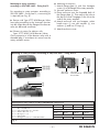
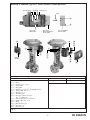
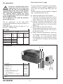
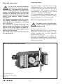
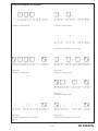
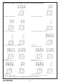
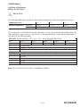
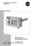
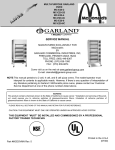
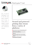
Mounting and Operating Instructions
Limit Switch Type 3776
Fig. 1
Contents
General notes
Mounting
Mounting to SAMSON Type 3278 Rotary Actuators
Mounting to rotary actuators according to VDI/VDE 3845 – fixing level 1
Mounting to rotary actuators according to VDI/VDE 3845 – fixing level 2
Mounting to SAMSON Type 3277 Linear Actuators without positioner
Mounting to SAMSON Type 3277-5 Linear Actuators (external) without positioner
Mounting to SAMSON Type 3277-5 Linear Actuators (internal) without positioner
Air connection
Filter elements for air supply
Exhaust air filters/degree of protection
Restrictors
Electrical connection
Connecting cables
Pilot valve/manual operation function
Connecting diagrams
Contacts
Displacement of the switching point due to changes in temperature
Inductive pick-ups
Inductive double proximity switch
Electric microswitches
Certifications
Certificate of Conformity PTB No. Ex-97.D.2107
Edition: July 1999
2
2
3
4
5
6
8
10
12
12
13
13
14
14
14
15
19
19
20
21
22
23
23
EB 8368 EN
General notes
Mounting
m
m
The device may only be assembled,
started up, and operated by experienced personnel familiar with this
product. Proper shipping and appropriate storage of the device are assumed.
In these Mounting and Operating Instructions,
the term “experienced personnel“ refers to persons, who are able to evaluate the responsibilities assigned to them as well as recognize potential hazards due to their specialized training, knowledge, and experience as well as
their special knowledge of the relevant standards.
Staff handling/operating ex-proof devices in
hazardous areas must be specially trained or
instructed, i. e. authorized to handle/operate
ex-proof devices.
For technical data, ordering data, spare parts
and accessories, see Data Sheet T 8368 EN.
Before mounting to actuators, all
relevant parts of the plant must be
depressurized.
In view of the high surface resistance, the device shall be mounted and serviced in hazardous areas, so that no electrostatic charging is
to be expected.
The coated screws in the enclosure must not
be tampered with.
Using mounting kits, the devices can be mounted to SAMSON Type 3278 Rotary Actuators,
to rotary actuators according to VDI/VDE 3845
and to SAMSON Types 3277 and 3277-5
Linear Actuators. Then the relevant mounting
instructions must be observed (see page 3 ff.).
The devices can be mounted in any desired
position to SAMSON Type 3277 Linear
Actuators. The devices must not be mounted to
rotary actuators or valves with NAMUR rib
with the bottom of the enclosure upwards, to
prevent water entering the enclosure. The
exhaust air filter in the enclosure cover and the
cable gland must be installed vertically downwards or, if this is not possible, horizontally.
On mounting, it is important that a clearance
of 300 mm minimum above the enclosure cover
be observed.
EB 8368 EN
–2–
Mounting to SAMSON Type 3278
Rotary Actuators
For mounting to SAMSON Type 3278 Rotary
Actuators (see Data Sheet T 8321 EN and Mounting and Operating Instructions EB 8321 EN), a
mounting kit is required (see Fig. 2).
E Devices with Type 3777-X030 Booster Valve
Insert plug according to the “external“ function
into the output bore at the flange of the booster
valve (as-delivered condition).
E Exhaust air return for devices with
Types 3777-X030/-X63X Booster Valves
Close connection 4 of the booster valve with a
threaded plug, if no exhaust air return from the
rotary actuator ensues.
E Mounting instructions
1 Attach plate h with two hexagon socket
head screws i to the flange of the rotary
actuator.
2 Attach flange plate e with four hexagon
screws f to the flange of the rotary actuator.
3 Place driver g through the plate h onto the
stub of the rotary actuator.
4 Unscrew enclosure cover.
5 Place enclosure onto the threaded bolts of
the flange plate e. Then adjust the stub at
the device so that it engages in the slit at the
driver g.
6 Attach enclosure with two hexagon socket
head screws a, two split washers b, two
washers c and two O-rings d.
7 Attach enclosure cover.
Mounting to SAMSON Type 3278 Rotary Actuators
Plug
a
b
c
d
fe
”external”
Type 3776
Limit Switch
i
h
Type 3777
Connection Block/
Booster Valve
Type 3777-X030
Booster Valve
g
d
c
b
a
Mounting kit for SAMSON Type 3278 Rotary Actuators
Order no.
1400-7216
1400-7217
a 2 u Hexagon socket head screw
M 6 u 12 DIN 912
b 2 u Split washer DIN 127 – form B 6
c 2 u Washer DIN 125 – 6.4
d 2 u O-ring 7.5 u 1.5
e 1 u Flange plate
f 4 u Hexagon screw M 5 u 12 DIN EN 24 017
g 1 u Driver
h 1 u Plate
i 2 u Hexagon socket head screw
M 4 u 10 DIN 912
Diaphragm area 160 cm2
Diaphragm area 320 cm2
Fig. 2
–3–
EB 8368 EN
Mounting to rotary actuators
according to VDI/VDE 3845 – fixing level 1
For mounting to rotary actuators according to
VDI/VDE 3845 – fixing level 1, a mounting kit
is required (see Fig. 3).
E Devices with Type 3777-X030 Booster Valve
Insert plug according to the “external“ function
into the output bore at the flange of the booster
valve (as-delivered condition).
E Exhaust air return for devices with
Types 3777-X030/-X63X Booster Valves
Close connection 4 of the booster valve with a
threaded plug, if no exhaust air return from the
rotary actuator ensues.
E Mounting instructions
1 Attach flange plate e with two hexagon
screws g and two hexagon nuts h onto the
bracket of the rotary actuator.
2 Place driver f onto the stub of the rotary
actuator.
3 Unscrew enclosure cover.
4 Place enclosure onto the threaded bolts of
the flange plate e. Then adjust the stub at
the device so that it engages in the slit at the
driver f.
5 Attach enclosure with two hexagon socket
head screws a, two split washers b, two
washers c and two O-rings d.
6 Attach enclosure cover.
Mounting to rotary actuators according to VDI/VDE 3845 – fixing level 1
Plug
”external”
abcd
abcd
Type 3776
Limit Switch
e
f
gh
Mounting kit for rotary actuators according to VDI/VDE 3845 – fixing level 1
Order no.
1400-7041
a 2 u Hexagon socket head screw
M 6 u 12 DIN 912
b 2 u Split washer DIN 127 – form B 6
c 2 u Washer DIN 125 – 6.4
d 2 u O-ring 7.5 u 1.5
e 1 u Flange plate
f 1 u Driver
g 2 u Hexagon screw M 6 u 12 DIN EN 24 017
h 2 u Hexagon nut M 6 DIN EN 24 032
Fig. 3
EB 8368 EN
–4–
Type 3777
Connection Block/
Booster Valve
Type 3777-X030
Booster Valve
Mounting to rotary actuators
according to VDI/VDE 3845 – fixing level 2
For mounting to rotary actuators according to
VDI/VDE 3845 – fixing level 2, a mounting kit
is required (see Fig. 4).
E Devices with Type 3777-X030 Booster Valve
Insert plug according to the “external“ function
into the output bore at the flange of the booster
valve (as-delivered condition).
E Mounting instructions
1 Attach flange plate e with four hexagon
screws f to the flange of the rotary actuator.
2 Unscrew enclosure cover.
3 Place enclosure onto the threaded bolts of
the flange plate e. Then adjust the stub at
the device so that it engages in the slit at the
stub of the rotary actuator.
4 Attach enclosure with two hexagon socket
head screws a, two split washers b, two
washers c and two O-rings d.
5 Attach enclosure cover.
E Exhaust air return for devices with
Types 3777-X030/-X63X Booster Valves
Close connection 4 of the booster valve with a
threaded plug, if no exhaust air return from the
rotary actuator ensues.
Mounting to rotary actuators according to VDI/VDE 3845 – fixing level 2
Plug
”external”
abcd
abcd
Type 3776
Limit Switch
Type 3777
Connection Block/
Booster Valve
Type 3777-X030
Booster Valve
e
f
Mounting kit for rotary actuators according to VDI/VDE 3845 – fixing level 2
Order no.
1400-7043
1400-7186
1400-7212
1400-7210
a 2 u Hexagon socket head screw
M 6 u 12 DIN 912
b 2 u Split washer DIN 127 – form B 6
c 2 u Washer DIN 125 – 6.4
d 2 u O-ring 7.5 u 1.5
e 1 u Flange plate
f 4 u Hexagon screw M 5 u 12 DIN EN 24 017
Size 1
Size 2
Size 3
Size 4
80 mm
130 mm
130 mm
30 mm
50 mm
Hole spacing A
80 mm
Shaft stub length B
20 mm
30 mm
Fig. 4
–5–
EB 8368 EN
Mounting to SAMSON Type 3277
Linear Actuators without positioner
For mounting to SAMSON Type 3277 Linear
Actuators (see Data Sheet T 8311 EN and Mounting and Operating Instructions EB 8311 EN), a
mounting kit is required (see Fig. 5).
E Devices without pilot valve
Replace exhaust air filter in the enclosure cover with a threaded plug n, because aeration
ensues via cover m at the linear actuator.
Screw exhaust air filter into cover m.
E Devices with pilot valve
Replace exhaust air filter in the enclosure cover with a threaded plug n, because aeration
ensues via cover m at the linear actuator.
Screw exhaust air filter into cover m.
With devices with two exhaust air filters (see
“Exhaust air filter/degree of protection“, page
13), one exhaust air filter remains in the enclosure cover.
E Devices with Type 3777-X030 Booster Valve
Insert plug according to the “external“ function
into the output bore at the flange of the booster
valve (as-delivered condition).
Insert O-ring o into the output bore on the bottom side of the booster valve.
E Exhaust air return for devices with
Types 3777-X030/-X63X Booster Valves
Close connection 4 of the booster valve with a
threaded plug, if no exhaust air return from the
linear actuator ensues.
EB 8368 EN
E Mounting instructions
1 Break out the threaded plug from the bottom of the enclosure by turning respectively
with a screw driver.
2 Insert molded gasket a into the groove at
the bottom of the enclosure.
3 Attach driver b with the spring insert on
the outside onto the stub and lock it with the
snap ring c.
4 Stick flat gasket e onto the bottom side of
the flange plate d.
5 Attach flange plate d with two hexagon
screws f rightside at the yoke of the linear
actuator. Put the washer g and the O-ring
h under the left hexagon screw f.
6 Attach clamping lever i to the actuator
stem of the linear actuator.
7 Unscrew enclosure cover.
8 Place enclosure onto the threaded bolts of
the flange plate d. Then adjust the stub so
that the pin at the clamping lever i engages
in the slit at the driver b.
9 Attach enclosure with two hexagon socket
head screws j, two split washers k and
two washers l.
10 Replace the indicating cap with the black
covering cap p, because the valve position
indication ensues at the actuator stem of the
linear actuator. Attach and turn covering
cap p onto the cam holder until it engages.
11 Attach enclosure cover.
12 Attach cover m rearside at the yoke of the
linear actuator.
–6–
Mounting to SAMSON Type 3277 Linear Actuators without positioner
Threaded plug
abc
Spring insert
Plug
o
”external”
n
Type 3776
Limit Switch
Type 3777
Connection Block/
Booster Valve
Type 3777-X030
Booster Valve
m
p
f
i
j
k
l
i
d
e
Exhaust
air filter
d
h
g
f
l
k
j
n
Mounting kit for SAMSON Type 3277 Linear Actuators
Order no.
1400-7220
a
b
c
d
e
f
g
h
i
j
1u
1u
1u
1u
1u
2u
1u
1u
1u
2u
Diaphragm area 240/350 cm2 Diaphragm area 700 cm2
k
l
m
n
o
p
2u
2u
1u
2u
1u
1u
Molded gasket
Driver
Snap ring x 5 u 0.8
Flange plate
Flat gasket
Hexagon screw M 5 u 12 DIN EN 24 017
Washer DIN 125 – 5.3
O-ring 5 u 1.2
Clamping lever
Hexagon socket head screw
M 6 u 12 DIN 912
Split washer DIN 127 – form B 6
Washer DIN 125 – 6.4
Cover
Threaded plug 1/4“
O-ring 4 u 2
Covering cap
1400-7221
Fig. 5
–7–
EB 8368 EN
Mounting to SAMSON Type 3277-5
Linear Actuators (external) without positioner
For mounting to SAMSON Type 3277-5 Linear
Actuators with external routing of the loading
pressure (see Data Sheet T 8311 EN and Mounting and Operating Instructions EB 8311 EN), a
mounting kit is required (see Fig. 6).
E Devices without pilot valve
Replace ventilation plug/exhaust air filter in
the enclosure cover with a threaded plug n,
because aeration ensues via cover m at the
linear actuator.
Screw ventilation plug/exhaust air filter into
cover m.
E Devices with pilot valve
Replace exhaust air filter in the enclosure cover with a threaded plug n, because aeration
ensues via cover m at the linear actuator.
Screw exhaust air filter into cover m.
With devices with two exhaust air filters (see
“Exhaust air filter/degree of protection“, page
13), one exhaust air filter remains in the enclosure cover.
E Devices with Type 3777-X030 Booster Valve
Insert plug according to the “external“ function
into the output bore at the flange of the booster
valve (as-delivered condition).
Insert O-ring o into the output bore on the bottom side of the booster valve.
EB 8368 EN
E Mounting instructions
1 Break out the threaded plug from the bottom of the enclosure by turning respectively
with a screw driver.
2 Insert molded gasket a into the groove at
the bottom of the enclosure.
3 Attach driver b with the spring insert on
the outside onto the stub and lock it with the
snap ring c.
4 Stick flat gasket e onto the bottom side of
the flange plate d.
5 Attach flange plate d with two hexagon
screws f rightside at the yoke of the linear
actuator. Put the washer g and the O-ring
h under the left hexagon screw f.
6 Attach clamping lever i onto the actuator
stem of the linear actuator.
7 Unscrew enclosure cover.
8 Place enclosure onto the threaded bolts of
the flange plate d. Then adjust the stub so
that the pin at the clamping lever i engages
in the slit at the driver b.
9 Attach enclosure with two hexagon socket
head screws j, two split washers k and
two washers l.
10 Replace the indicating cap with the black
covering cap p, because the valve position
indication ensues at the actuator stem of the
linear actuator. Attach and turn covering
cap p onto the cam holder until it engages.
11 Attach enclosure cover.
12 Attach cover m rearside at the yoke of the
linear actuator.
–8–
Mounting to SAMSON Type 3277-5 Linear Actuators (external) without positioner
Threaded plug
abc
Spring insert
Plug
o
”external”
n
Type 3776
Limit Switch
Type 3777
Connection Block/
Booster Valve
Type 3777-X030
Booster Valve
m
p
f
j
k
l
i
i
d
d
e
h
g
f
l
k
j
Exhaust
air filter
n
Mounting kit for SAMSON Type 3277-5 Linear Actuators (external)
Order no.
a
b
c
d
e
f
g
h
i
j
1u
1u
1u
1u
1u
2u
1u
1u
1u
2u
k
l
m
n
o
p
2u
2u
1u
2u
1u
1u
1400-7219
Molded gasket
Driver
Snap ring x 5 u 0.8
Flange plate
Flat gasket
Hexagon screw M 5 u 12 DIN EN 24 017
Washer DIN 125 – 5.3
O-ring 5 u 1.2
Clamping lever
Hexagon socket head screw
M 6 u 12 DIN 912
Split washer DIN 127 – Form B 6
Washer DIN 125 – 6.4
Cover
Threaded plug 1/4“
O-ring 4 u 2
Covering cap
Fig. 6
–9–
EB 8368 EN
Mounting to SAMSON Type 3277-5
Linear Actuators (internal) without positioner
For mounting to SAMSON Type 3277-5 Linear
Actuators with internal routing of the loading
pressure (see Data Sheet T 8311 EN and Mounting and Operating Instructions EB 8311 EN), a
mounting kit is required (see Fig. 7).
E Devices with Type 3777-X030 Booster Valve
Only devices with Type 3777-X030 Booster
Valve can be mounted to SAMSON Type
3277-5 Linear Actuators with internal routing
of the loading pressure. Then the loading
pressure is connected optionally to the bottom
or the top diaphragm chamber via the holes in
the yoke and via a switch-over plate.
EB 8368 EN
E Mounting instructions
1 Unscrew booster valve from enclosure (see
“Air connection“, page 12).
2 Insert plug according to the “internal“ function into the output bore at the flange of the
booster valve.
3 Attach booster valve to the enclosure.
4 Close connection 2 with the threaded plug
p and the sealing ring q.
5 Close connection 4 with a threaded plug n.
6 Insert O-ring o into the output bore on the
bottom side of the booster valve.
7 Break out the threaded plug from the bottom of the enclosure by turning respectively
with a screw driver.
8 Insert molded gasket a into the groove on
the bottom of the enclosure.
9 Attach driver b with the spring insert on
the outside onto the stub and lock it with the
snap ring c.
10 Stick flat gasket e onto the bottom side of
the flange plate d.
11 Attach flange plate d with two hexagon
screws f rightside at the yoke of the linear
actuator. Put the washer g and the O-ring
h under the left hexagon screw f.
12 Attach clamping lever i to the actuator
stem of the linear actuator.
13 Unscrew enclosure cover.
14 Place enclosure onto the threaded bolts of
the flange plate d. Then adjust the stub so
that the pin at the clamping lever i engages
in the slit at the driver b.
15 Attach enclosure with two hexagon socket
head screws j, two split washers k and
two washers l.
16 Replace the indicating cap with the black
covering cap p, because the valve position
indication ensues at the actuator stem of the
linear actuator. Attach and turn covering
cap p onto the cam holder until it engages.
17 Attach enclosure cover.
18 Attach cover m rearside at the yoke of the
linear actuator.
19 Replace exhaust air filter in the enclosure
cover with a threaded plug n, because
aeration ensues via cover m at the linear
actuator.
20 Screw exhaust air filter into cover m.
– 10 –
Mounting to SAMSON Type 3277-5 Linear Actuators (internal) without positioner
Threaded plug
abc
Spring insert
Plug
o
qp
”internal”
n
Type 3777-X030
Booster Valve
Type 3776
Limit Switch
j
k
l
r
m
f
i
i
d
d
e
h
g
f
l
k
j
Exhaust
air filter
n
Mounting kit for SAMSON Type 3277-5 Linear Actuators (internal)
Order no.
1400-7222
1400-7223
a
b
c
d
e
f
g
h
i
j
1u
1u
1u
1u
1u
2u
1u
1u
1u
2u
Connection G 1/4
Connection NPT 1/4
k
l
m
n
o
p
q
r
2u
2u
1u
2u
1u
1u
1u
1u
Molded gasket
Driver
Snap ring x 5 u 0.8
Flange plate
Flat gasket
Hexagon screw M 5 u 12 DIN EN 24 017
Washer DIN 125 – 5.3
O-ring 5 u 1.2
Clamping lever
Hexagon socket head screw
M 6 u 12 DIN 912
Split washer DIN 127 – Form B 6
Washer DIN 125 – 6.4
Cover
Threaded plug 1/4“
O-ring 4 u 2
Hexagon head socket pipe plug DIN 908 – 1/4“
Sealing ring 13.5 u17 u1.5 (only for G 1/4)
Covering cap
Fig. 7
– 11 –
EB 8368 EN
Air connection
Filter elements for air supply
m
To protect the pilot valve against dirt particles,
connection 9 for air supply is equipped with a
sieve, mesh size 100 µm, and a filter, pore size
30 µm.
The filter elements must be cleaned or replaced
when contaminated (see Fig. 8).
For devices with pilot valve, the air
supply pipes and screw joints may
only be laid and assembled by
experienced personnel. They must be regularly
checked for leaks and damage and, if necessary, repaired. Before starting any repair
work, all supply pipes which are to be opened
must be depressurized.
The air supply must not exceed the maximum
permissible pressure.
The air connections on the Type 3777
Connection Block/Booster Valve are G (NPT) 1/4
tapped holes.
Preferably angle connectors for pipe 6 u 2 or
hose 4 u 1 shall be used.
Air supply
Instrument air
Ambient
temperature
(°C)
r15 … r35
s15
s32
s60
2.2 … 10 bar
Dew
Particle
point
size
(°C)
(µm)
r10
≤5
s20
s40
s70
Oily
residues
(mg/m3)
≤ 0.1
E Cleaning/replacing the filter elements
1 Screw out sieve h from connection 9 with a
screw driver (screw driver point 7 to 9 mm).
Clean/replace and screw into connection 9.
2 Remove connection block/booster valve
from the enclosure after removal of two hexagon socket head screws f and two split
washers g.
3 Pull out filter d from the enclosure.
Clean/replace and reinsert into the enclosure. Be sure to check that the seal ring c is
positioned correctly.
4 Attach connection block/booster valve with
two hexagon socket head screws f and two
split washers g to the enclosure. Before
mounting, be sure to check that the seals a
or e and the two O-rings b are positioned
correctly.
Air connection
b
Spare parts
Order no.
a
b
c
d
e
1890-3891
0430-1155
0430-1134
0550-0653
1890-3892
Seal with restrictor
O-ring 6 u 1
Seal ring 12 u 2
Filter
Seal with ball
(only if one pilot valve is used)
f Hexagon socket head screw
M 4 u 30 DIN 912
g Split washer DIN 127 – form B 4
h Sieve
a cda
e
8333-1191
8392-0654
0550-0213
Fig. 8
EB 8368 EN
b
– 12 –
fhf
g g
Exhaust air filter/degree of protection
Restrictors
E Devices without pilot valve
These devices are equipped either with a ventilation plug (IP 54), a filter (IP 54), or a filter
check-valve (IP 65) in the enclosure cover.
For mounting to SAMSON Types 3277 and
3277-5 Linear Actuators, the ventilation plug
must be replaced with an exhaust air filter.
E Devices with Types 3777-X632/-XX53
Booster Valve
These devices are equipped with supply air
restrictors/exhaust air restrictors (see Fig. 9).
Different closing and opening times can be
adjusted by turning the restricting screws a
and b to the right (opening) or to the left
(closing) using a screw driver (e. g. for rotary
actuators at a ratio of 1:15).
With closed restricting screws, a minimum of
flow is guaranteed.
E Devices with pilot valve
These devices are equipped either with one or
two filters (IP 54), or one or two filter checkvalves (IP 65) in the enclosure cover.
The quantity of exhaust air filters depends on
the K vs value of the booster valve/connection
block (see table).
Connection block/Booster valve Exhaust air
Type
K vs value
filter
3777-X010
0.01
1u
3777-X020
0.01
1u
3777-X030
0.20
1u
3777-X630
0.30
2u
3777-X632
0.18
1u
3777-XX50
0.30
2u
3777-XX53
0.23
2u
m
Important note for devices with
Types 3777-XXXX index -01
Booster valve
E Devices with Types 3777
-X030-01/-X630-01/-X650-01/-X250-01/
-X350-01/-X450-01/-X550-01
Booster Valve
These devices include baffle plates with a diameter of 3 mm in the output connections. Do
not remove the baffle plates, otherwise the
reliable functioning cannot be guaranteed.
Restrictors
Booster valve
Type
Connection
Restrictors
Function
K vs value
3777-X632 2
2
a Exhaust air 0.01 … 0.18
b Supply air
3777-XX53 4
2
a Exhaust air 0.01 … 0.23
b Exhaust air
a
b
Fig. 9
– 13 –
EB 8368 EN
Electrical connection
Connecting cables
m
The power supply is connected either through
cable glands M 20 u1,5 to a terminal in the
enclosure, with plug-type connectors according
to DIN 43 650, with plug-type connectors
(manufactured by Harting) or with round
connectors (manufactured by Binder).
It is recommended that connecting cables with
a conductor cross-section of 0.5 mm2 and an
external diameter of 6 to 9 mm are used.
As far as the electrical installation
of the device is concerned, the relevant electrotechnical regulations
and the accident prevention regulations of the
country in which the device is used must be
observed. In Germany these are the VDE
regulations and the accident prevention regulations of the emloyers´ liability insurance
association.
For mounting in hazardous areas, the respective national regulations of the country in
which the device is used applies. In Germany
this is VDE 0165.
For connection to certified intrinsically safe
electric circuits, the Certificate of Conformity
PTB No. Ex-97.D.2107 applies (see page 23).
When connected to DC voltage signals, correct
polarity must be ensured.
The coated screws in the enclosure must not
be tampered with.
Pilot valve/manual operation function
m
For safety circuits, only pilot valves
without manual operation function
should be used.
E Devices with pilot valve
The pilot valve, which conists of an E/P binary
converter a and a pressure reducer b, is optionally provided with a manual operation
function c (see Fig. 10).
When a nominal signal is not available, the
pilot valve can be operated by a pushbutton or
a pushbutton switch using a screw driver (screw
driver point 4.5 mm).
Pilot valve/manual operation function
a b
c
a E/P binary converter
b Pressure reducer
c Manual operation function
Fig. 10
EB 8368 EN
– 14 –
Connection diagrams for terminal
3 inductive contacts (2-wire)
2 inductive contacts (3-wire)
2 electric contacts (change-over contacts)
2 pilot valves
3 inductive contacts (2-wire)
1 pilot valve
3 inductive contacts (3-wire)
2 pilot valves
2 inductive contacts (3-wire)
1 pilot valve
3 electric contacts (change-over contacts)
2 pilot valves
2 electric contacts (change-over contacts)
Fig. 11
– 15 –
EB 8368 EN
Connection diagrams for plug-type connectors according to DIN 43 650
2 inductive contacts (2-wire)
1 inductive contact (3-wire)
2 inductice contacts (3-wire)
1 electric contact (change-over contact)
2 electric contacts (change-over contacts)
1 pilot valve
1 inductive contact (2-wire)
1 pilot valve
3 inductive contacts (2-wire)
2 pilot valves
2 inductive contacts (2-wire)
2 pilot valves
1 inductive contact (3-wire)
2 pilot valves
1 electric contact (change-over contact)
Fig. 12 · ● = Coding (only if 2 plug-type connectors are used)
EB 8368 EN
– 16 –
Connection diagrams for plug-type connectors (manufatured by Harting)
1 pilot valve
3 inductive contacts (2-wire)
1 pilot valve
2 inductive contacts (3-wire)
1 pilot valve
2 electric contacts (change-over contacts)
2 pilot valves
2 inductive contacts (2-wire)
2 pilot valves
1 inductive contacts (3-wire)
2 pilot valves
3 inductive contacts (2-wire)
2 pilot valves
3 inductive contacts (3-wire)
1 pilot valve
1 electric contact (change-over contact)
2 pilot valves
3 electric contacts (change-over contacts)
Fig. 13 · ● = Coding (only if 2 plug-type connectors are used)
– 17 –
EB 8368 EN
Connection diagrams for round connectors (manufactured by Binder)
3 inductive contacts (2-wire)
2 inductive contacts (3-wire)
2 electric contacts (change-over contacts)
1 pilot valve
2 inductive contacts (2-wire)
1 pilot valve
2 inductive contacts (3-wire)
2 pilot valves
1 inductive contact (3-wire)
2 pilot valves
3 inductive contacts (3-wire)
2 pilot valves
3 inductive contacts (2-wire)
2 pilot valves
3 electric contacts (change-over contacts)
Fig. 14 · ● = Coding (only if 2 round connectors are used)
EB 8368 EN
– 18 –
Contacts
The devices are either equipped with inductive
pick-ups, inductive double proximity switch or
electric microswitches (see page 20 ff.).
For most applications, the contacts are adjusted to provide a signal when the actuator has
reached one of its end positions. The switching
point can also be adjusted to any position within the rotary range or travel range to signalize
an intermediate position.
Displacement of the switching point
due to changes in temperature
The contacts and their actuating appliances are
sensitive to changes in temperature.
In order to ensure safe switching, the switching
hysteresis between the switching position of the
actuator and the switching point of the contact
must be larger than the displacement of the
switching point due to changes in temperature.
For this reason, when adjusting the contacts,
the displacement of the switching point must be
compensated for with x rotation of the adjusting
screw (see table “Adjustment data“).
Adjustment data
Displacement of the switching point
Angle of rotation
Travel
≤ 2°
≤ 0.8 mm
Rotation of the adjusting screw
x = 1/16
x = 1/16
∆T = 50 K
– 19 –
EB 8368 EN
E Adjusting the switching points
1 Unscrew enclosure cover.
2 Pull off indicating cap/black covering cap
from the cam holder.
3 Move control valve to the desired switching
position.
4 Turn adjusting screw d with a screw driver,
until the metal tag b moves out of the magnetic field of the pick-up c and the output
signal changes from “0“ to “1“.
5 To compensate for the displacement of the
switching point due to changes in temperature, turn adjusting screw d with x rotation
in the opposite direction (see table
“Adjustment data“, page 19).
6 Move control valve out of the switching position and check whether the output signal
changes from “1“ to “0“.
7 Move control valve to the switching position
again and check the switching point.
8 Attach and turn indicating cap/black covering cap onto the cam holder until it engages.
9 Attach enclosure cover.
Inductive pick-ups
For devices with inductive pick-ups c, the
shaft a is equipped with up to three adjustable
metal tags b (see Fig. 15).
When the metal tag is within the magnetic field
of the pick-up, the initiator becomes attenuated
and the output high-resistant (switching function
“contact open“). When the metal tag is no more
within the magnetic field, the pick-up is unattenuated and the output low-resistant
(switching function “contact closed“).
If the devices have been attached by the manufacturer, the metal tags are adjusted, so that
the pick-ups are unattenuated in the switching
positions of the control valve (switching function
“contact closed“).
Adjusting the switching points for inductive pick-ups
c d
b
a
b
c
d
a
Shaft
Metal tag
Inductive pick-up
Adjusting screw
Fig. 15 · Device without enclosure cover and indicating cap/black covering cap
EB 8368 EN
– 20 –
E Adjusting the switching points
1 Unscrew enclosure cover.
2 Pull off indicating cap/black covering cap
from the cam holder.
3 Move control valve to the switching position
„closed“.
4 Turn adjusting screw d with a screw driver,
until the metal tag b moves out of the magnetic field of the proximity switch „closed“
and the output signal changes from “0“ to
“1“.
5 To compensate for the displacement of the
switching point due to changes in temperature, turn adjusting screw d with x rotation
in the opposite direction (see table
“Adjustment data“, page 19).
6 Move control valve to the switching position
“open“ and check whether the output signal
of proximity switch “open“ changes from
“0“ to “1“.
7 Move control valve to the switching position
“closed“ again and check the switching
point.
8 Attach and turn indicating cap/black covering cap onto the cam holder until it engages.
9 Attach enclosure cover.
Inductive double proximity switch
For devices with inductive double proximity
switch c, the shaft a is equipped with an
adjustable metal tag b with an angle of rotation of 70° or 90° (see Fig. 16).
When the metal tag is within the magnetic field
of the proximity switch, the initiator becomes
attenuated and the output high-resistant
(switching function “contact open“). When the
metal tag is no more within the magnetic field,
the proximity switch is unattenuated and the
output low-resistant (switching function
“contact closed“).
The metal tag is designed, so that in the switching positions of the control valve the proximity
switches are unattenuated (switching function
“contact closed“).
When the device is mounted to a rotary actuator
turned by 90°, the connecting cables of the
proximity switches must be changed to signalize
the switching positions “closed“ and “open“
correctly.
Adjusting the switching points for inductive double proximity switch
a
a
b
c
d
Shaft
Metal tag
Inductive double proximity switch
Adjusting screw
b
c
d
Fig. 16 · Device without enclosure cover and indicating cap/black covering cap
– 21 –
EB 8368 EN
Electric microswitches
m
The covering plate under the enclosure cover must not be removed.
For devices with electric microswitches, the
shaft a is equipped with up to three adjustable
cam disks b. Each cam disk b actuates an
electric microswitch c by means of the roller
mounted to the switch lever d (see Fig. 17).
The electric microswitches have a change-over
contact which can be used as normally open
contact or normally closed contact.
E Adjusting the switching points
1 Unscrew enclosure cover.
2 Pull off indicating cap/black covering cap
from the cam holder.
3 Move control valve to the desired switching
position.
4 Turn adjusting screw e with a screw driver,
until the cam disk b actuates the microswitch c and the output signal changes.
5 To compensate for the displacement of the
switching point due to changes in temperature, turn adjusting screw d with x rotation
in the opposite direction (see table
“Adjustment data“, page 19).
6 Move control valve out of the switching position and check whether the output signal
changes.
7 Move control valve to the switching position
again and check the switching point.
8 Attach and turn indicating cap/black covering cap onto the cam holder until it engages.
9 Attach enclosure cover.
Adjusting the switching points for electric microswitches
b
a
b
c
d
e
Shaft
Cam disk
Electric microswitch
Switch lever
Adjusting screw
a
c
e d
Fig. 17 · Device without enclosure cover, indicating cap/black covering cap and covering plate
EB 8368 EN
– 22 –
Certifications
Certificate of Conformity
PTB No. Ex-97.D.2107
EEx ia IIC T6
The following table shows the permissible ambient temperature within the temperature classes:
Temperature class
Ambient temperature
maximum
minimum
T6
r60 °C
s45 °C
T5
r70 °C
T4
r80 °C
For connection to a certified intrinsically safe electric circuit, the maximum permissible values for
input voltage Ui, input current Ii, input power Pi, internal inductance Li and internal capacitance Ci
are shown in the following table:
Pilot valve (Screw terminals r81, s82, r83, s84 or plug-type connector)
Ui
25 V
27 V
28 V
30 V
32 V
Ii
150 mA
125 mA
115 mA
100 mA
90 mA
Pi
no power limit
Li
negligible
Ci
negligible
Initiator (Screw terminals r41, s42, r45, s46, r51, s52 or plug-type connector)
Ui
16 V
Ii
52 mA
Pi
169 mW
Li
250 µH
Ci
60 nF
Note: The Certificate of Conformity is available on request.
– 23 –
EB 8368 EN
SAMSOMATIC
AUTOMATIONSSYSTEME
GMBH
– A subsidiary of SAMSON AG
Weismüllerstrasse 20 – 22
D-60314 Frankfurt am Main
P. O. Box 10 19 01
D-60019 Frankfurt am Main
Telephone +49-69-4 00 90
Telefax +49-69-4 00 96 44
A
(Specifications subject to change without notice)