1
BA 245F/00/en/11.03
Nr. 52011936
Valid as of software version:
V 01.02.00 (amplifier)
V 01.02.00 (communication)
levelflex M
FMP 40, FMP 41 C, FMP 45
with HART, PROFIBUS-PA
and Foundation Fieldbus
Guided Level-Radar
Description of Instrument Functions
TM
HART
R
FIELD COMMUNICATION PROTOCOL
F
TM
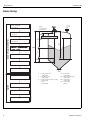
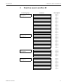
Basic Setup
Levelflex M
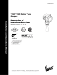
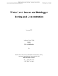
Basic Setup
tank shape
flange:
reference point of
measurement
Standard
measuring cond.
UB
basic setup (standard)
Unknown
D SD
measuring cond.
Standard
E
LN
F
L
empty calibr.
LB
full calibr.
mapping
E = empty calibr. (= zero)
setting in 005
F = full calibr. (= span)
setting in 006
D = distance (distance flange / product)
display in 0A5
L = level
display in 0A6
safety settings
extended calibr.
...
2
(description see BA 245F)
option
linearisation
LN = probe length
setting in 033
UB = upper blocking distance
setting in 059
SD = safety distance
setting in 015
LB = lower blocking
distance
Endress+Hauser
Levelflex M
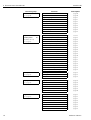
Table of contents
Table of contents
1
Notes on use . . . . . . . . . . . . . . . . . . . . . . . 5
5.5
Function "determine length" (034) . . . . . . . . . . 31
1.1
6
Function group
"linearisation" (04) . . . . . . . . . . . . . . . . 32
1.4
1.5
1.6
Using the table of contents to locate
a function description . . . . . . . . . . . . . . . . . . . 5
Using the graphic of the function menu
to locate a function description . . . . . . . . . . . . 5
Using the index of the function menu
to locate a function description . . . . . . . . . . . . 5
General structure of the operating menu . . . . . 6
Display and operating elements . . . . . . . . . . . 7
Commissioning . . . . . . . . . . . . . . . . . . . . . . . 10
2
Function menu Levelflex M . . . . . . . 11
6.1
6.2
6.3
6.4
6.5
6.6
6.7
6.8
Function "level/ullage" (040) . . . . . . . . . . . . . . 32
Function "linearisation" (041) . . . . . . . . . . . . . . 33
Function "customer unit" (042) . . . . . . . . . . . . 37
Function "table no." (043) . . . . . . . . . . . . . . . . 38
Function "input level" (044) . . . . . . . . . . . . . . . 38
Function "input volume" (045) . . . . . . . . . . . . . 39
Function "max. scale" (046) . . . . . . . . . . . . . . 39
Function "diameter vessel" (047) . . . . . . . . . . 39
3
Function group
"basic setup" (00) . . . . . . . . . . . . . . . . . . 14
7
Function group
"extended calibr." (05) . . . . . . . . . . . . 40
3.1
3.2
3.3
3.4
3.5
3.6
3.7
3.8
3.9
3.10
3.11
3.12
3.13
3.14
3.15
3.16
Function "measured value" (000) . . . . . . . . . .
Function "tank properties" (002) . . . . . . . . . . .
Function "medium property" (003) . . . . . . . . .
Function "process propert." (004) . . . . . . . . .
Function "end of probe" (030) . . . . . . . . . . . .
Function "probe length" (031) . . . . . . . . . . . .
Function "probe" (032) . . . . . . . . . . . . . . . . . .
Function "probe length" (033) . . . . . . . . . . . .
Function "determine length" (034) . . . . . . . . .
Function "empty calibr." (005) . . . . . . . . . . . .
Function "full calibr." (006) . . . . . . . . . . . . . . .
Display (008) . . . . . . . . . . . . . . . . . . . . . . . . .
Function "check distance" (051) . . . . . . . . . .
Function "range of mapping" (052) . . . . . . . .
Funktion "start mapping" (053) . . . . . . . . . . . .
Display (008) . . . . . . . . . . . . . . . . . . . . . . . . .
7.1
7.2
7.3
7.4
7.5
7.6
7.7
7.8
7.9
7.10
Function "selection" (050) . . . . . . . . . . . . . . . . 40
Function "check distance" (051) . . . . . . . . . . . 40
Function "range of mapping" (052) . . . . . . . . . 41
Function "start mapping" (053) . . . . . . . . . . . . 41
Function "pres. map dist." (054) . . . . . . . . . . . 42
Function "delete mapping" (055) . . . . . . . . . . 42
Function "echo quality" (056) . . . . . . . . . . . . . 43
Function "offset" (057) . . . . . . . . . . . . . . . . . . . 43
Function "output damping" (058) . . . . . . . . . . 44
Funktion "upper block.dist" (059) . . . . . . . . . . 44
8
Function group "output" (06),
- "profibus param." (06),
PROFIBUS-PA only . . . . . . . . . . . . . . . 45
8.1
4
Function group
"safety settings" (01) . . . . . . . . . . . . . . 23
4.1
4.2
4.3
4.4
4.5
4.6
4.7
4.8
4.9
4.10
Function "output on alarm" (010) . . . . . . . . . .
Function "output on alarm" (011), HART only .
Function "outp. echo loss" (012) . . . . . . . . . .
Function "ramp %span/min" (013) . . . . . . . . .
Function "delay time" (014) . . . . . . . . . . . . . .
Function "safety distance" (015) . . . . . . . . . .
Function "in safety dist." (016) . . . . . . . . . . . .
Function "ackn. alarm" (017) . . . . . . . . . . . . .
Function "overspill prot." (018) . . . . . . . . . . . .
Function "broken probe det" (019) . . . . . . . . .
5
Function group
"length adjustment" (03) . . . . . . . . . . 30
5.1
5.2
5.3
5.4
Function "end of probe" (030) . . . . . . . . . . . .
Function "probe length" (031) . . . . . . . . . . . .
Function "probe" (032) . . . . . . . . . . . . . . . . . .
Function "probe length" (033) . . . . . . . . . . . .
Function "commun. address" (060),
HART only . . . . . . . . . . . . . . . . . . . . . . . . . . . . 45
Function "instrument addr." (060),
PROFIBUS-PA only . . . . . . . . . . . . . . . . . . . . . 45
Function "no. of preambels" (061),
HART only . . . . . . . . . . . . . . . . . . . . . . . . . . . . 46
Function "ident number" (061),
PROFIBUS-PA only . . . . . . . . . . . . . . . . . . . . . 46
Function "low output limit" (062),
HART only . . . . . . . . . . . . . . . . . . . . . . . . . . . . 47
Function "set unit to bus" (062),
PROFIBUS-PA only . . . . . . . . . . . . . . . . . . . . . 47
Function "curr. output mode" (063),
HART only . . . . . . . . . . . . . . . . . . . . . . . . . . . . 48
Function "out value" (063),
PROFIBUS-PA only . . . . . . . . . . . . . . . . . . . . . 48
Function "fixed cur. value" (064),
HART only . . . . . . . . . . . . . . . . . . . . . . . . . . . . 49
Function "out status" (064),
PROFIBUS-PA only . . . . . . . . . . . . . . . . . . . . . 49
Function "simulation" (065) . . . . . . . . . . . . . . . 50
Function "simulation value" (066) . . . . . . . . . . 51
Function "output current" (067),
1.2
1.3
Endress+Hauser
14
14
15
16
16
17
17
17
17
18
18
20
20
21
21
22
23
25
25
26
27
27
27
29
29
29
30
30
30
31
8.2
8.3
8.4
8.5
8.6
8.7
8.8
8.9
8.10
8.11
8.12
8.13
3
Table of contents
HART only . . . . . . . . . . . . . . . . . . . . . . . . . . .
8.14 Function "2nd cyclic value" (067),
PROFIBUS-PA only . . . . . . . . . . . . . . . . . . . .
8.15 Function "4mA value" (068),
HART only . . . . . . . . . . . . . . . . . . . . . . . . . . .
8.16 Function "select v0h0" (068),
PROFIBUS-PA only . . . . . . . . . . . . . . . . . . . .
8.17 Function "20mA value" (069),
HART only . . . . . . . . . . . . . . . . . . . . . . . . . . .
8.18 Function "display value" (069),
PROFIBUS-PA only . . . . . . . . . . . . . . . . . . . .
9
Levelflex M
53
11.4
11.5
11.6
11.7
11.8
Function "reset" (0A3) . . . . . . . . . . . . . . . . . .
Function "unlock parameter" (0A4) . . . . . . . .
Function "measured dist." (0A5) . . . . . . . . . .
Function "measured level" (0A6) . . . . . . . . . .
Function "application par." (0A8) . . . . . . . . .
53
12
Function group
"system parameters" (0C) . . . . . . . . . 67
52
52
54
54
Function group
"envelope curve" (0E) . . . . . . . . . . . . . 55
12.1 Function "tag no." (0C0) . . . . . . . . . . . . . . . .
12.2 Function "device tag" (0C0),
Foundation Fieldbus only . . . . . . . . . . . . . . .
12.3 Function "Profile Version" (0C1),
PROFIBUS-PA only . . . . . . . . . . . . . . . . . . . .
12.4 Function "protocol+sw-no." (0C2) . . . . . . . . .
12.5 Function "serial no." (0C4) . . . . . . . . . . . . . . .
12.6 Function "device id" (0C4),
Foundation Fieldbus only . . . . . . . . . . . . . . .
12.7 Function "distance unit" (0C5) . . . . . . . . . . . .
12.8 Function "download mode" (0C8) . . . . . . . . .
63
64
65
66
66
67
67
67
67
68
9.1
9.2
9.3
Function "plot settings" (0E1) . . . . . . . . . . . . . 55
Function "recording curve" (0E2) . . . . . . . . . . 55
Function "envelope curve display" (0E3) . . . . 56
10
Function group
"display" (09) . . . . . . . . . . . . . . . . . . . . . . 58
10.1
10.2
10.3
10.4
10.5
10.6
Function "language" (092) . . . . . . . . . . . . . . .
Function "back to home" (093) . . . . . . . . . . . .
Function "format display" (094) . . . . . . . . . . .
Function "no.of decimals" (095) . . . . . . . . . . .
Function "sep. character" (096) . . . . . . . . . . .
Function "display test" (097) . . . . . . . . . . . . . .
11
Function group
"diagnostics" (0A) . . . . . . . . . . . . . . . . . 61
15.1 Trouble-shooting instructions . . . . . . . . . . . . 73
15.2 System error messages . . . . . . . . . . . . . . . . 74
15.3 Application errors . . . . . . . . . . . . . . . . . . . . . 76
11.1 Function "present error" (0A0) . . . . . . . . . . . . 62
11.2 Function "previous error" (0A1) . . . . . . . . . . . 62
11.3 Function "clear last error" (0A2) . . . . . . . . . . . 62
Index function menu . . . . . . . . . . . . . . . . . . . 78
4
58
58
59
59
59
60
68
68
69
13
Function group
"service" (0D) . . . . . . . . . . . . . . . . . . . . . 70
14
Envelope curve . . . . . . . . . . . . . . . . . . . 71
15
Trouble-shooting . . . . . . . . . . . . . . . . . 72
Endress+Hauser
Levelflex M
1 Notes on use
1
Notes on use
You have various options for accessing the descriptions of instrument functions or how
to enter parameters.
1.1
Using the table of contents to locate a function
description
All the functions are listed in the table of contents sorted by function group (e.g.
basic setup, safety settings, etc.). You can access a more detailed description of a
function by using a page reference / link.
The table of contents is on page 3.
1.2
Using the graphic of the function menu to locate a
function description
This guides you step by step from the highest level, the function groups, to the exact
function description you require.
All the available function groups and instrument functions are listed in the table (see
page 11). Select your required function group or function. You can access an exact
description of the function group or function by using a page reference / link.
1.3
Using the index of the function menu to locate a
function description
To simply navigation within the function menu, each function has a position which is
shown in the display. You can access each function via a page reference/link in the
function menu index (see page 79) which lists all the function names alphabetically and
numerically.
Endress+Hauser
5
1 Notes on use
Levelflex M
1.4
General structure of the operating menu
The operating menu is made up of two levels:
• Function groups (00, 01, … , 0C, 0D):
The individual operating Selection of the instrument are split up roughly into different
function groups. The function groups that are available include, e.g.: "basic setup",
"safety settings", "output", "display", etc.
• Functions (001, 002, 003, …, 0D8, 0D9):
Each function group consists of one or more functions. The functions perform the
actual operation or parameterisation of the instrument. Numerical values can be entered here and parameters can be selected and saved. The available functions of the
“basic setup (00)” function group include, e.g.: "tank shape (002)", "medium
property (003)", "process cond. (004)", "empty calibr. (005)", etc.
If, for example, the application of the instrument is to be changed, carry out the following
procedure:
1. Select the “basic setup (00)” function group.
2. Select the "tank properties" (002) (where the existing tank properties is selected).
1.4.1
Identifying the functions
For simple orientation within the function menus (see Page 11 ff.), for each function a
position is shown on the display.
The first two digits identify the function group:
• basic setup
00
• safety settings
01
• lenght adjustment 02
…
he third digit numbers the individual functions within the function group:
• basic setup
00
→
• tank properties
002
• medium property 003
• process cond.
004
…
Hereafter the position is always given in brackets (e.g. "tank properties" (002)) after the
described function.
6
Endress+Hauser
Levelflex M
1 Notes on use
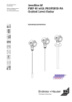
1.5
Display and operating elements
END
RES
R
IP
Maulburg
II
65
T
A >70°C
: t
>85°C
Made in Germany
Order MICR
S+HA
OPIL
Ser.-NoCode:
OT USE
.:
Messbe
Measur reich
ing
range
U 16...36
max.
4...20
20
m
mAV DC
LCD
(liquid crystal display)
ENDRESS + HAUSER
–
+
E
Symbols
Abb. 3
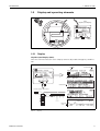
1.5.1
3 keys
Layout of the display and operating elements
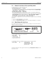
Display
Liquid crystal display (LCD):
Four lines with 20 characters each. Display contrast adjustable through key combination.
Headline
Position indicator
ENDRESS + HAUSER
Symbol
–
+
Main value
Unit
E
Selection list
Function groups -> Functions
HOME
X
F
O
S
Abb. 4
Endress+Hauser
FG00
FG01
FG02
FG03
FG04
FG05
FG06
FG07
...
X
F
F
F000 F001 F002 F003 F004 ...
F
O
S
X
X
Help text
+21mV
Envelope
curve
0.00
2.305m
09C
10.00
Display
7
1 Notes on use
Levelflex M
1.5.2
Display symbols
The following table describes the symbols that appear on the liquid crystal display:
Symbols
Meaning
ALARM_SYMBOL
This alarm symbol appears when the instrument is in an alarm state. If the symbol flashes, this
indicates a warning.
LOCK_SYMBOL
This lock symbol appears when the instrument is locked,i.e. if no input is possible.
COM_SYMBOL
This communication symbol appears when a data transmission via e.g. HART, PFOFIBUS-PA
or Foundation Fieldbus is in progress.
SIMULATION_SWITCH_ENABLE
This communication symbol appears when simulation in FF is enabled via the DIP switch.
Tab. 1
Meaning of Symbols
1.5.3
Key assignment
The operating elements are located inside the housing and are accessible for operation
by opening the lid of the housing.
Function of the keys
Key(s)
Meaning
O or V
Navigate upwards in the selection list
Edit numeric value within a function
S or W
Navigate downwards in the selection list
Edit numeric value within a function
X or Z
F or M
O and F
or
S and F
O and S and F
Tab. 2
8
Navigate to the left within a function group
Navigate to the right within a function group, confirmation.
Contrast settings of the LCD
Hardware lock / unlock
After a hardware lock, an operation of the instrument via display or
communication is not possible!
The hardware can only be unlocked via the display. An unlock parameter must
be entered to do so.
Function of the keys
Endress+Hauser
Levelflex M
1 Notes on use
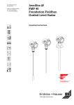
1.5.4
Operation with the VU 331
ENDRESS + HAUSER
–
+
X
E
F
2x
X
O
basic setup
F
safety settings
X
tank shape
O
Standard
F
aluminium tank
>3 s
medium property
...
Return to
Group Selection
O
plastic tank
linearisation
S
extended calibr.
...
S
X
bypass / pipe
coax probe
concrete wall
S
...
Selection and configuration in Operation menu:
1.) Change from Measured Value Display to Group Selection by pressing F
2.) Press S or O to select the required Function Group (e.g.. "basic setup (00)") and confirm by pressing
F ➜ First function (e.g. "tank shape (002)") is selected.
Note!
The active selection is marked by a ✔ in front of the menu text.
3.) Activate Edit mode with O or S.
Selection menus:
a) Select the required Parameter in selected function (e.g. "tank shape (002)") with S or O.
b) F confirms selection ➜ ✔ appears in front of the selected parameter
c) F confirms the edited value ➜ system quits Edit mode
d) O / S (= X) interrupts selection ➜ system quits Edit mode
Typing in numerals and text:
a) Press O or S to edit the first character of the numeral / text (e.g. "empty calibr. (005)")
b) F positions the cursor at the next character ➜ continue with (a) until you have completed your input
c) if a symbol appears at the cursor, press F to accept the value entered
➜ system quits Edit mode
d) O / S (= X) interrupts the input, system quits Edit mode
4) Press F to select the next function (e.g. "medium property (003)")
5) Press O / S (= X) once ➜ return to previous function (e.g. "tank shape (002)")
Press O / S (= X) twice ➜ return to Group selection
6) Press O / S (= X) to return to Measured value display
Abb. 5
Endress+Hauser
Selection and configuration in operation menu
9
1 Notes on use
Levelflex M
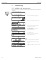
1.6
Commissioning
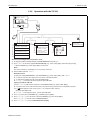
1.6.1
Switching on the measuring device
When the instrument is switched on for the first time, the following messages appear on
the display:
⇒
⇓
After 5 s, the following message appears
⇓
Nach 5 s erscheint (z.B. bei HART Geräten)
After 5 s or after you have pressed F the
following message appears
⇓
Select the language
(this message appears the first time the
instrument is switched on)
⇓
Select the basic unit
(this message appears the first time the
instrument is switched on)
⇓
⇓
⇒
The current measured value is displayed
After F is pressed, you reach the group
selection.
This selection enables you to perform the basic
setup
10
Endress+Hauser
Levelflex M
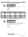
2 Function menu Levelflex M
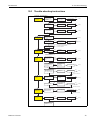
2
Function menu Levelflex M
Function group
basic setup
00
Function
⇒
(see page 14)
⇓
safety settings
01
⇒
(see page 23)
⇓
length adjustment
03
⇒
(see page 30)
⇓
Linearisation
(see page 32)
⇓
Endress+Hauser
04
⇒
Description
measured value
000
→
page 14
tank properties
002
→
page 14
medium property
003
→
page 15
process cond.
004
→
page 16
end of probe
030
→
page 16
probe length
031
→
page 17
probe
032
→
page 17
probe length
033
→
page 17
determine length
034
→
page 17
empty calibr.
005
→
page 18
full calibr.
006
→
page 18
check distance
051
→
page 20
range of mapping
052
→
page 21
start mapping
053
→
page 21
output on alarm
010
→
page 23
output on alarm (HART only)
011
→
page 25
outp. echo loss
012
→
page 25
ramp %span/min
013
→
page 26
delay time
014
→
page 27
safety distance
015
→
page 27
in safety dist.
016
→
page 27
ackn. alarm
017
→
page 29
overspill prot.
018
→
page 29
brocken probe det
019
end of probe
030
→
page 30
probe length
031
→
page 30
probe
032
→
page 30
probe length
033
→
page 31
determine length
034
→
page 31
level/ullage
040
→
page 32
linearisation
041
→
page 33
customer unit
042
→
page 37
table no.
043
→
page 38
input level
044
→
page 38
input volume
045
→
page 39
max. scale
046
→
page 39
diameter vessel
047
→
page 39
page 29
11
2 Function menu Levelflex M
Levelflex M
Function group
Function
selection
050
→
page 40
check distance
051
→
page 40
range of mapping
052
→
page 41
start mapping
053
→
page 41
pres. map dist.
054
→
page 42
delete map.
055
→
page 42
echo quality
056
→
page 43
offset
057
→
page 43
output damping
058
→
page 44
upper block.dist
059
→
page 44
commun. address (HART only)
060
→
Seite 45
instrument addr. (PROFIBUS-PA only)
060
→
page 45
PROFIBUS-PA only
no. of preambels (HART only)
061
→
page 46
(see page 45)
ident number (PROFIBUS-PA only)
061
→
page 46
low output limit (HART only)
062
→
page 47
set unit to bus (PROFIBUS-PA only)
062
→
page 47
curr. output mode
063
out value (PROFIBUS-PA only)
063
→
page 48
fixed cur. value (HART only)
064
→
page 49
out status (PROFIBUS-PA only)
064
→
page 49
simulation
065
→
page 50
simulation value
066
→
page 51
output current (HART only)
067
→
page 52
2nd cyclic value (PROFIBUS-PA only)
067
→
page 52
4mA value (HART only)
068
select v0h0 (PROFIBUS-PA only)
068
→
page 53
20mA value (HART only)
069
→
page 54
display value (PROFIBUS-PA only)
069
→
page 54
plot settings
0E1
→
page 55
recording curve
0E2
→
page 55
envelope curve
0E3
→
page 56
language
092
→
page 58
back to home
093
→
page 58
format display
094
→
page 59
no.of decimals
095
→
page 59
sep. character
096
→
page 59
display test
097
→
page 60
present error
0A0
→
page 62
previous error
0A1
→
page 62
clear last error
0A2
→
page 62
reset
0A3
→
page 63
unlock parameter
0A4
→
page 64
measured dist.
0A5
→
page 65
measured level
0A6
→
page 66
application par.
0A8
→
page 66
extended calibr.
05
⇒
(see page 40)
⇓
output
06
profibus param.
06
⇒
⇓
envelope curve
0E
⇒
(see page 55)
⇓
display
09
⇒
(see page 58)
⇓
diagnostics
(see page 61)
⇓
12
Description
0A
⇒
page 48
page 53
Endress+Hauser
Levelflex M
2 Function menu Levelflex M
Function group
system parameters
0C
Function
⇒
(see page 67)
⇓
service
Endress+Hauser
D00
⇒
Description
tag no.
0C0
→
page 67
device tag (Foundation Fieldbus only)
0C0
→
page 67
Profile Version (PROFIBUS-PA only)
0C1
→
page 67
protocol+sw-no.
0C2
→
page 67
serial no.
0C4
→
page 68
device id (Foundation Fieldbus only)
0C4
→
page 68
distance unit
0C5
→
page 68
download mode
0C8
→
page 69
service level
D00
page 70
13
3 Function group "basic setup" (00)
Levelflex M
3
Function group "basic setup" (00)
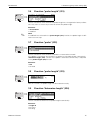
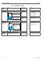
3.1
Function "measured value" (000)
⇒
⇒
This function displays the current measured value in the selected unit
(see "customer unit" (042) function). The number of places after decimal point can be
selected in the "no.of decimals" (095) function.
3.2
Function "tank properties" (002)
⇒
This function is used to select the tank properties.
Selection:
• standard
• aluminium tank
• plastic tank
• bypass / pipe
• coax probe
• concrete wall
standard
The "standard" option is recommended for normal containers for rod and rope probes.
aluminium tank
The "aluminium tank" option is designed especially for high aluminium silos that cause
an increased level of noise when empty. This option is only useful for probes
longer than (< 4 m). For short probes (< 4 m) select the "standard" option.
!
Note!
If "aluminium tank" is selected, the device calibrates of its own accord when first filled,
depending on the medium's properties. Slope errors can, therefore, occur when beginning the first filling procedure.
plastic tank
Select the "plastic tank" option when installing probes in wood or plastic containers without metallic surfaces at the process connection (see installation in plastic containers).
When using a metallic surface at the process connection, the "standard" option is sufficient.
!
14
Note!
In principle the employment of a metallic surface area should be preferred at the process connection!
Endress+Hauser
Levelflex M
3 Function group "basic setup" (00)
bypass / pipe
The "bypass / pipe" option is designed especially for the installation of probes in a
bypass or a stilling well.
coax probe
Select the "coax probe" option when using a coaxial probe. When this setting is made,
the evaluation is adapted to the high sensitivity of the coax probe. This option should,
therefore, not be selected when using rope or rod probes.
concrete wall
The "concrete wall" option takes into account the signal-damping property of concrete
walls when mounting with < 1 m distance to the wall.
3.3 Function "medium property" (003)
⇒
This function is used to select the dielectric constant.
Selection:
• unknown
• 1.4 ... 1.6
• 1.6 ... 1.9
• 1.9 ... 2.5
• 2.5 ... 4.0
• 4.0 ... 7.0
• > 7.0
Product class
DK (εr)
0
unknown
1
1,4 … 1,6
2
1,6 … 1,9
– Plastic granules
– White lime, special cement
– Sugar
–
–
–
–
3
1,9 … 2,5
– Portland cement, plasters
– Mineral oils, fuels
30 m
4
2,5 … 4
– Cereals, seeds
– Ground stone
– Sand
– Benzene, styrene, toluene
– Furan
– Naphthalene
35 m
5
4…7
– Naturally-moist (ground) stone, ores
– Salt
– Chlorobenzene, chloroform
– Cellulose spray
– Isocyanate, aniline
35 m
6
>7
– Metal powder
– Watery fluids
– Alcohols
– Ammoniac
35 m
Typical bulk solids
Typical liquids
– Liquefied gases, e.g. N2, CO2
Liquefied gas, e.g. propane
Solvents
Freon 12 / freon
Palm oil
Typical measuring
range
4 m, coax probe only
25 m
The lower group applies to very loose or loosened bulk solids.
Reduction of the max. possible measuring range by means of:
• extremely loose surfaces of bulk solids, e.g. bulk solids with low piled density when
filled pneumatically.
• Build-up, primarily of moist products.
Endress+Hauser
15
3 Function group "basic setup" (00)
3.4
Levelflex M
Function "process propert." (004)
⇒
Use this function to adapt the device reaction to the filling speed in the tank. The setting
impacts on an intelligent filter.
Selection:
• standard
• fast change
• slow change
• test:no filter
Selection:
standard
fast change
Application:
For all normal applications,
bulk solids and fluids at low
to medium filling speed and
sufficiently large tanks.
Small tanks, primarily with
fluids, at high filling speeds.
Applications with strong
surface movement, e.g.
caused by stirrer, primarily
large tanks with slow to
medium filling speed.
Shortest reaction time:
• For test purposes
• Measurement in small
tanks at high filling
speeds, if "rapid change"
setting is too slow.
2-wire electronics:
Dead time: 4 s
Slewrate: 18 s
Dead time: 2 s
Slewrate: 5 s
Dead time: 6 s
Slewrate: 40 s
Dead time: 1 s
Slewrate: 0 s
4-wire electronics:
Dead time: 2 s
Slewrate: 11 s
Dead time: 1 s
Slewrate: 3 s
Dead time: 3 s
Slewrate: 25 s
Dead time: 0,7 s
Slewrate: 0 s
3.5
slow change
test:no filter
Function "end of probe" (030)
⇒
Use this function to select the polarity of the probe end signal. If the probe end is
uncovered or in an insulated attachment, there is a negative probe end signal.
The signal from the probe end is positive if the attachment is grounded.
Only the setting "free " is permitted for the FMP 41C.
Selection:
• free
• tie down isol.1
• tie down gnd.1
1.FMP 41C: These settings lead to a false output signal for empty tanks.
16
Endress+Hauser
Levelflex M
3 Function group "basic setup" (00)
3.6
Function "probe length" (031)
⇒
Use this function to select whether the probe length was changed after factory calibration. Only then is it necessary to enter or correct the probe length.
Selection:
• not modified
• modified
!
Note!
If "modified" was selected in the "probe length" (031) function, the probe length is defined in the next step.
3.7
Function "probe" (032)
⇒
Use this function to select whether the probe is uncovered or covered.
If the probe is uncovered, the Levelflex can determine the probe length automatically
"determine length" (034). function. If the probe is covered, a correct entry is required
in the "probe length" (033) function
Selection:
• free
• covered
3.8
Function "probe length" (033)
⇒
With this function, the probe length can be entered manually.
3.9
Function "determine length" (034)
⇒
Use this function to determine the probe length automatically.
Selection:
• length ok
• too short
• too long
Endress+Hauser
17
3 Function group "basic setup" (00)
Levelflex M
After selection "length too short" or "length too long", the calculation of the new value
need approx. 10 s.
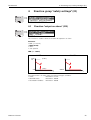
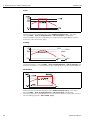
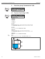
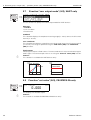
3.10 Function "empty calibr." (005)
⇒
This function is used to enter the distance from the flange (reference point of the measurement) to the minimum level (=zero).
E = empty calibration (= zero)
E
Emax = probe length – lower blocking distance
0%
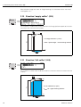
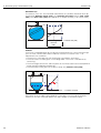
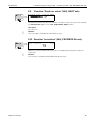
3.11 Function "full calibr." (006)
⇒
This function is used to enter the distance from the minimum level to the maximum level
(=span).
100%
F = full calibration (= span)
F
Fmax = E – upper blocking distance
0%
18
Endress+Hauser
Levelflex M
3 Function group "basic setup" (00)
!
Note!
The usable measuring range lies between the lower and the upper blocking distance.
The values for empty distance (E) and span (F) can be set independently of this.
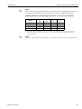
Blocking distance and measuring range for Dk ≥ 1.6 (1.4 for coax probes):
FMP 40
LN [m]/"
UB [m]/"
LB [m]/"
min
max
min
min
1/40
35/1378
0,2/8 1)
0,25/10
6 mm rod probe
0,3/12
2/80
0,2/8 1)
0,05/2
16 mm rod probe
0,3/12
4/178
0,2/8 1)
0,05/2
Coax probe
0,3/12
4/178
0/0
0,05/2
Rope probe
1) The indicated blocking distances are prearised. At media with DK >7, the upper blocking distance
UB can be reduced for rod- and rope probes on 0.1m. The upper blocking distance UB can be
entered manually.
!
Endress+Hauser
Note!
Within the upper and lower blocking distance, a reliable measurement can not be guaranteed.
19
3 Function group "basic setup" (00)
Levelflex M
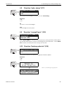
3.12 Display (008)
⇒
The distance measured from the reference point to the product surface and the meas.
value calculated with the aid of the empty adjustment are displayed. Check whether the
values correspond to the actual meas. value or the actual distance. The following cases
can occur:
• Distance correct – meas. value correct -> continue with the next function,
"check distance" (051)
• Distance correct – meas. value incorrect -> Check "empty calibr." (005)
• Distance incorrect – meas. value incorrect -> continue with the next function,
"check distance" (051)
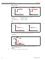
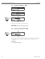
3.13 Function "check distance" (051)
⇒
This function triggers the mapping of interference echoes. To do so, the measured
distance must be compared with the actual distance to the product surface. The
following options are available for selection:
Selection:
• distance = ok
• dist. too small
• dist. too big
• dist. unknown
• manual
• probe free
distance too small
distance = ok
+
+
distance = ok
Use this function at part-covered probe. Choosing function "manual" or "probe free" at
free probe.
• mapping is carried out up to the currently measured echo
• The range to be suppressed is suggested in the "range of mapping (052)" function
Anyway, it is wise to carry out a mapping even in this case.
20
Endress+Hauser
Levelflex M
3 Function group "basic setup" (00)
!
Note!
At free probe, the mapping should be confirmed with the choice "probe free".
dist. too small
• At the moment, an interference is being evaluated
• Therefore, a mapping is carried out including the presently measured echoes
• The range to be suppressed is suggested in the "range of mapping (052)" function
dist. too big
• This error cannot be remedied by interference echo mapping
• Check the application parameters (002), (003), (004) and "empty calibr." (005)
dist. unknown
If the actual distance is not known, no mapping can be carried out.
manual
A mapping is also possible by manual entry of the range to be suppressed. This entry
is made in the "range of mapping (052)" function.
"
Caution!
The range of mapping must end 0.3 m (20") before the echo of the actual level. In case
of empty vessel it is possible to make a map over the whole probe length.
probe free
If the probe is uncovered, mapping is carried out along the whole probe length.
"
Caution!
Only begin mapping in this function if the probe is safely uncovered. Otherwise, the
device will not make correct measurements.
3.14 Function "range of mapping" (052)
⇒
This function displays the suggested range of mapping. The reference point is always
the reference point of the measurement (see Page 2 ff.). This value can be edited by the
operator.
For manual mapping, the default value is 0,3 m.
3.15 Funktion "start mapping" (053)
⇒
This function is used to start the interference echo mapping up to the distance given in
"range of mapping" (052).
Selection:
• off:
no mapping is carried out
• on:
mapping is started
Endress+Hauser
21
3 Function group "basic setup" (00)
Levelflex M
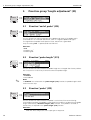
3.16 Display (008)
⇒
The distance measured from the reference point to the product surface and the meas.
value calculated with the aid of the empty alignment are displayed again. Check
whether the values correspond to the actual meas. value or the actual distance. The
following cases can occur:
• Distance correct – meas. value correct -> basic setup completed
• Distance incorrect – meas. value incorrect -> a further interference echo mapping
must be carried out "check distance" (051).
• Distance correct – meas. value incorrect -> check "empty calibr." (005)
⇒
⇓
!
22
After 3 s, the following message appears
Note!
After the basic setup, an evaluation of the measurement with the aid of the envelope
curve ("envelope curve" (0E)" function group) is recommended.
Endress+Hauser
Levelflex M
4 Function group "safety settings" (01)
4
Function group "safety settings" (01)
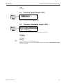
4.1
Function "output on alarm" (010)
⇒
⇒
This function is used to select the reaction of output on an alarm.
Selection:
• MIN (<= 3.6mA)
• MAX (22mA)
• hold
• user specific
MIN (<= 3.6mA)
HART
PA / FF
[mA]
22
(110%)
3.6
(-10%)
-99999
t
t
If the instrument is in alarm state, the output changes as follows:
• HART:
MIN-Alarm 3.6 mA
• PROFIBUS-PA:
MIN-Alarm -99999
• Foundation Fieldbus: MIN-Alarm -99999
Endress+Hauser
23
4 Function group "safety settings" (01)
Levelflex M
MAX 110% 22mA
HART
[mA]
22
PA / FF
(110%)
+99999
(-10%)
3.6
t
t
If the instrument is in alarm state, the output changes as follows:
• HART:
MAX-Alarm 22 mA
• PROFIBUS-PA:
MAX-Alarm +99999
• Foundation Fieldbus:
MAX-Alarm +99999
hold
HART
[mA]
22
PA / FF
(110%)
110 %
Hold
3.6
Hold
(-10%)
-10 %
t
t
If the instrument is in alarm state, the last measured value is held.
user specific
If the instrument is in alarm state, the output is set to the value configured in
"output on alarm" (011) (x mA).
"
24
Caution!
This selection is available for HART devices only!
Endress+Hauser
Levelflex M
4 Function group "safety settings" (01)
4.2
Function "output on alarm" (011), HART only
⇓
⇒
On alarm, the output current is in mA. This function is active when you selected "user
specific" in the "output on alarm" (010) function.
"
Caution!
This function is available for HART devices only!
4.3
Function "outp. echo loss" (012)
⇒
Use this function to set the output response on echo loss.
Selection:
• alarm
• hold
• ramp %/min
L00-FMR2xxxx-05-00-00-en-005
alarm
On echo loss, the instrument switches to alarm state after an adjustable
"delay time" (014). The output response depends on the configuration set in
"output on alarm" (010).
Endress+Hauser
25
4 Function group "safety settings" (01)
Levelflex M
L00-FMR2xxxx-05-00-00-en-006
hold
On echo loss, a warning is generated after a definable "delay time" (014). Output is
held.
L00-FMR2xxxx-05-00-00-en-007
ramp %/min
On echo loss, a warning is generated after a definable "delay time" (014). The output is
changed towards 0% or 100% depending on the slope defined in "ramp %span/min"
(013).
4.4
⇒
Function "ramp %span/min" (013)
⇓
Ramp slope which defines the output value on echo loss. This value is used if
"ramp %span/min" is selected in "outp. echo loss" (012). The slope is given in % of the
measuring range per minute.
26
Endress+Hauser
Levelflex M
4 Function group "safety settings" (01)
4.5
Function "delay time" (014)
⇒
Use this function to enter the delay time (Default = 30 s) after which a warning is
generated on echo loss, or after which the instrument switches to alarm state.
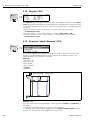
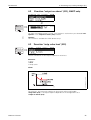
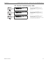
4.6
Function "safety distance" (015)
A configurable safety distance is placed before the "blocking dist." (059) (see
page 44). This distance warns you that any further level increase would make the measurement invalid.
blocking dist. (059)
blocking dist. (059)
safety distance (015)
safety distance (015)
⇒
Enter the size of the safety distance here. The default value is: 0.1 m.
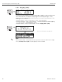
4.7
Function "in safety dist." (016)
⇒
This function defines the response when the level enters the safety distance .
Selection:
• alarm
• warning
• self holding
Endress+Hauser
27
4 Function group "safety settings" (01)
Levelflex M
alarm
Instrument enters the defined alarm state ("output on alarm" (011)). The alarm
message E651 - "level in safety distance - risk of overspill" is displayed.
If the level drops out of the safety distance, the alarm warning disappears and the
instrument starts to measure again.
warning
[mA]
22
SD
3.6
[mA]
110%
22
SD
WARNING WARNING
110%
-10%
t
-10%
t
3.6
Instrument displays a warning E651 - "level in safety distance - risk of overspill", but
continues to measure. If the level leaves the safety distance, the warning disappears.
self holding
Instrument switches to defined alarm state ("output on alarm" (011)). The alarm
message E651 - "level in safety distance - risk of overspill" is displayed.
If the level leaves the safety distance, the measurement continues only after a reset of
the self holding (function: "ackn. alarm" (017)).
28
Endress+Hauser
Levelflex M
4 Function group "safety settings" (01)
4.8
Function "ackn. alarm" (017)
⇒
This function acknowledges an alarm in case of "self holding".
Selection:
• no
• yes
no
The alarm is not acknowledged.
yes
Acknowledgement takes place.
4.9
Function "overspill prot." (018)
⇒
When "german WHG" is selected, various parameters relating to WHG overflow protection are defaulted and the instrument is locked against further operation. Select "Standard" to unlock, the WHG parameter settings are retained.
4.10 Function "broken probe det" (019)
⇒
This function activates the automatic recognition of broken probes.
Selection:
• off
• on
⇒
⇓
Endress+Hauser
After 3 s, the following message appears
29
5 Function group "length adjustment" (03)
Levelflex M
5
Function group "length adjustment" (03)
5.1
Function "end of probe" (030)
⇒
⇒
Use this function to select the polarity of the probe end signal. If the probe end is
uncovered or in an insulated attachment, there is a negative probe end signal.
The signal from the probe end is positive if the attachment is grounded.
Only the setting "free " is permitted for the FMP 41C.
Selection:
• free
• tie down isol.1
• tie doen gnd.1
5.2
Function "probe length" (031)
⇒
Use this function to select whether the probe length was changed after factory calibration. Only then is it necessary to enter or correct the probe length.
Selection:
• modified
• not modified
!
Note!
If "modified" was selected in the "probe length" (031) function, the probe length is defined in the next step.
5.3
Function "probe" (032)
⇒
Use this function to select whether the probe is at the time of the commisioning
uncovered or covered. If the probe is uncovered, the Levelflex can determine the probe
length automatically "determine length" (034). function. If the probe is covered, a
correct entry is required in the "probe length" (033) function
Selection:
1.FMP 41C: These settings lead to a false output signal for empty tanks.
30
Endress+Hauser
Levelflex M
5 Function group "length adjustment" (03)
• free
• covered
5.4
Function "probe length" (033)
⇒
Use this function to enter the probe length.
5.5
Function "determine length" (034)
⇒
Use this function to determine the probe length automatically.
Selection:
• length ok
• too short
• too long
#
Endress+Hauser
Warning!
Use this function only if the probe is free.
After the automatic calculation of the probe length, the function "check distance" (051)
must be activated.
31
6 Function group "linearisation" (04)
Levelflex M
6
Function group "linearisation" (04)
6.1
Function "level/ullage" (040)
⇒
⇒
Selection:
• level CU
• level DU
• ullage CU
• ullage DU
level CU
Level in customer units. The measured value can be linearised.
The "linearisation" (041) default value is set to a linear 0...100%.
level DU
Level in the selected "distance unit" (0C5).
ullage CU
Ullage in customer units. The value can be linearised.
The "linearisation" (041) default value is set to a linear 0...100%.
ullage DU
Ullage in the selected "distance unit" (0C5).
!
32
Note!
Reference point for the ullage is "full calibr." (006) (=span).
Endress+Hauser
Levelflex M
6 Function group "linearisation" (04)
6.2
Function "linearisation" (041)
Linearisation defines the ratio of level to container volume or product weight and allows
a measurement in customer units, e.g. metres, hectolitres etc. The measured value in
(000) is then displayed in the selected unit.
⇒
This function is used to select the linearisation modes.
Selection:
• linear
• horizontal cyl
• manual
• semi-automatic
• table on
• clear table
linear
The tank is linear e.g. a cylindrical vertical tank. You can measure in customer units by
entering a maximum volume/weight.
You can select the "customer unit" (042). Define the volume value corresponding to the
calibration in "max. scale" (046). This value corresponds to an output of 100% (= 20 mA
for HART).
20
mA
4
mA
100%
0%
kg, m3, ft3, ... = customer unit (042)
max.scale
(046)
Endress+Hauser
33
6 Function group "linearisation" (04)
Levelflex M
horizontal cyl
The volume, mass etc. are calculated automatically in cylindrical horizontal tanks by
entering the "diameter vessel" (047), the "customer unit" (042) and the "max. scale"
(046). The "max. scale" (046) corresponds to an output of 100% (= 20 mA for HART).
20
mA
100%
7)
(04
es
rv
te
me
l
se
dia
4
mA
0%
kg, m3, ft3, ... = customer unit (042)
max.scale
(046)
manual
If the level is not proportional to the volume or weight within the set measuring range,
you can enter a linearisation table in order to measure in customer units. The
requirements are as follows:
• The 32 (max.) value pairs for the linearisation curve points are known.
• The level values must be given in ascending order. The curve is monotonously
increasing.
• The level heights for the first and last points on the linearisation curve correspond to
empty and full calibration respectively.
• The linearisation takes place in the basic setup unit ("distance unit" (0C5)).
20
mA
100%
(2)
(3)
4
mA
0%
(4)
kg, m3, ft3, ... = customer unit (042)
Each point (2) in the table is described by a value pair: level (3) and, for example,
volume (4). The last value pair defines the 100% output (= 20 mA for HART).
34
Endress+Hauser
Levelflex M
6 Function group "linearisation" (04)
⇒
⇓
Select the table point (Point 3).
⇓
Enter the level belonging to Point 3.
⇓
Enter the corresponding volume.
⇓
Enter a further table point?
⇓
Next table point.
⇓
...
Continue until "next point" (045) is answered with
no.
!
!
Note!
After making entries into the table, activate it with "table on".
The 100% value (=20 mA for HART) is defined by the last point in the table.
Note!
Before confirming 0.00 m as the level or 0.00% as the volume, activate the Edit mode
with O or S.
Entries can be made into the linearisation table in ToF Tool using the table editor.
You can also display the contents graphically.
In addition, linearisation curves can be calculated for any tank shape.
Endress+Hauser
35
6 Function group "linearisation" (04)
Levelflex M
semi-automatic
The tank is filled in stages when the linearisation curve is entered semi-automatically.
The Levelflex automatically detects the level and the corresponding volume/weight has
to be entered.
The procedure is similar to manual table entry, where the level value for each table point
is given automatically by the instrument.
!
Note!
If the tank is emptied, pay attention to the following points:
• The number of points must be known in advance.
• The first table number = (32 - number of points).
• Entries in "Tab. no." (043) are made in reverse order (last entry = 1).
table on
An entered linearisation table only becomes effective when activated.
clear table
Before making entries into the linearisation table, any existing tables must be deleted.
The linearisation mode automatically switches to linear.
!
36
Note!
A linearisation table can be deactivated by selecting "linear" or "horizontal cyl" (or the
"level/ullage" (040) function = "level DU", "ullage DU"). It is not deleted and can be
reactivated at any time by selecting "table on".
Endress+Hauser
Levelflex M
6 Function group "linearisation" (04)
6.3
Function "customer unit" (042)
⇒
You can select the customer unit with this function.
Selection:
•%
•l
• hl
• m3
• dm3
• cm3
• ft3
• us_gal
• i_gal
• kg
•t
• lb
• ton
•m
• ft
• mm
• inch
Dependence
The units of the following parameters are changed:
• measured value (000)
• input volume (045)
• max. scale (046)
• simulation value (066)
Endress+Hauser
37
6 Function group "linearisation" (04)
6.4
Levelflex M
Function "table no." (043)
⇓
⇓
⇒
⇓
Position of the value pair in the linearisation table.
Dependence
Updates "input level" (044) , "input volume" (045).
6.5
⇒
Function "input level" (044)
⇓
⇓
You can enter the level for each point of the linearisation curve with this function. When
the linearisation curve is entered semi-automatically, Levelflex detects the level
automatically.
User input:
Level in "distance unit" (0C5).
38
Endress+Hauser
Levelflex M
6 Function group "linearisation" (04)
6.6
Function "input volume" (045)
⇓
⇒
⇓
⇓
⇓
Specify the volume for each point of the linearisation curve with this function.
User input:
Volume in "customer unit" (042).
6.7
Function "max. scale" (046)
⇒
You can enter the end value of the measuring range with this function. This input is
necessary if you selected "linear" or "horizontal cyl" in the "linearisation" (041)
function.
6.8
⇒
Function "diameter vessel" (047)
⇓
Enter the tank diameter with this function. This entry is necessary if you selected
"horizontal cyl" in the "linearisation" (041) function.
Endress+Hauser
39
7 Function group "extended calibr." (05)
Levelflex M
7
Function group "extended calibr." (05)
7.1
Function "selection" (050)
⇒
⇒
Select the function of the extended calibration.
Selection:
• common (e.g. "Level correction", "Output damping", etc.)
• mapping
• delete mapping
7.2
Function "check distance" (051)
⇒
This function triggers the mapping of interference echoes. To do so, the measured
distance must be compared with the actual distance to the product surface. The
following options are available for selection:
Selection:
• distance = ok
• dist. too small
• dist. too big
• dist. unknown
• manual
• probe free
distance too small
distance = ok
+
+
40
Endress+Hauser
Levelflex M
7 Function group "extended calibr." (05)
distance = ok
• mapping is carried out up to the currently measured echo
• The range to be suppressed is suggested in the "range of mapping (052)" function
Anyway, it is wise to carry out a mapping even in this case.
dist. too small
• At the moment, an interference is being evaluated
• Therefore, a mapping is carried out including the presently measured echoes
• The range to be suppressed is suggested in the "range of mapping (052)" function
dist. too big
• This error cannot be remedied by interference echo mapping
• Check the application parameters (002), (003), (004) and "probe length" (033)
dist. unknown
If the actual distance is not known, no mapping can be carried out.
manual
A mapping is also possible by manual entry of the range to be suppressed. This entry
is made in the "range of mapping (052)" function.
"
Caution!
The range of mapping must end 0.3 m (12") before the echo of the actual level.
7.3
Function "range of mapping" (052)
⇒
This function displays the suggested range of mapping. The reference point is always
the reference point of the measurement (see Page 2 ff.). This value can be edited by the
operator.
For manual mapping, the default value is 0.3 m.
7.4
Function "start mapping" (053)
⇒
This function is used to start the interference echo mapping up to the distance given in
"range of mapping" (052).
Selection:
• off:
no mapping is carried out
• on:
mapping is started
Endress+Hauser
41
7 Function group "extended calibr." (05)
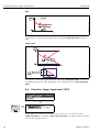
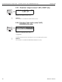
7.5
Levelflex M
Function "pres. map dist." (054)
⇒
Displays the distance up to which a mapping has been recorded.
A value of 0 indicates that no mapping was recorded so far.
pres. map dist. (054)
7.6
Function "delete mapping" (055)
⇒
This function allows cancellation of the available mapping.
Selection:
• no
• yes
no
The available mapping is not cancelled and remains active.
yes
After mapping is cancelled, the device skips to the
"dist./meas.value" (008) display.
42
Endress+Hauser
Levelflex M
7 Function group "extended calibr." (05)
7.7
Function "echo quality" (056)
⇒
20 mA
100%
4 mA
0%
echo quality (056)
The echo quality is the benchmark for measurement reliability. It describes the amount
of reflected energy and depends primarily on the following conditions:
• Dielectric constant of the medium
• probe type
• Distance between sensor and product
Low values increase the probability that the echo is lost through a change in measurement conditions, e.g. angel s of repose or large measuring distance.
7.8
Function "offset" (057)
⇒
This function corrects the measured level by a constant value. The entered value is
added to the measured level.
Endress+Hauser
43
7 Function group "extended calibr." (05)
7.9
Levelflex M
Function "output damping" (058)
⇒
Influences the time an output requires to react to a sudden level jump (63% of steady
state). A high value attenuates, for example, the influences of rapid changes on the
measured variable.
User input:
0...255 s
The default value depends on the selected application parameter
"process cond." (004).
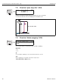
7.10 Funktion "upper block.dist" (059)
⇒
A window under the process connection can be suppressed when there are strong
reflections near the process connection or nearby internals, long nozzles or struts.
• The blocking distance is measured from the bottom edge of the process connection.
The standard top blocking distance is 200 mm (coax 0 mm).
• All echos are suppressed within this blocking distance.
• As the level echo could possibly be suppressed (and there is no guarantee that no
other significant echo is available), a 10 cm long safety distance is placed in front of
the blocking distance (see "safety distance" (015) function on page 27).
• The customer can set the Levelflex to respond to circumstances when the product is
within this zone (safety distance) (see page 27).
⇒
⇓
44
After 3 s, the following message appears
Endress+Hauser
Levelflex M
8 Function group "output" (06), - "profibus param." (06), PROFIBUS-PA only
8
Function group "output" (06),
- "profibus param." (06), PROFIBUS-PA only
⇒
Display at HART and Foundation
Fieldbus instrument
⇒
Display at PROFIBUS-PA instrument
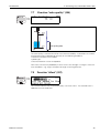
8.1
Function "commun. address" (060), HART only
⇒
Enter the communication address for the instrument with this function.
• Standard: 0
• Multidrop: 1-15
In multidrop mode, the standard output current is 4 mA. This can be changed in the
"fixed cur. value" (064) function.
"
Caution!
This function is available for HART devices only!
8.2
Function "instrument addr." (060),
PROFIBUS-PA only
⇒
The PA bus address is displayed in this field. The address is set either directly on the
instrument using DIP switches (see instrument operating instructions) or using a special
SetSlaveAddress command via the bus, e.g. by the ToF Tool.
"
Endress+Hauser
Caution!
This function is available for PROFIBUS-PA devices only!
45
8 Function group "output" (06), - "profibus param." (06), PROFIBUS-PA only
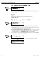
8.3
Levelflex M
Function "no. of preambels" (061), HART only
⇒
Enter the number of preambles for the HART protocol with this function.
An increase in the value is advisable for "bad" lines with communications problems.
"
Caution!
This user input is available for HART devices only!
8.4
Function "ident number" (061), PROFIBUS-PA only
⇒
• manufacturer
• profile
manufacturer
Set to1522 hex according to manufacturer (PNO registered).
profile
Setting defined as in PA Profile 3.0: 9700 hex - instrument with one AI block.
"
46
Caution!
This function is available for PROFIBUS-PA devices only!
Endress+Hauser
Levelflex M
8 Function group "output" (06), - "profibus param." (06), PROFIBUS-PA only
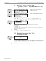
8.5
Function "low output limit" (062), HART only
⇒
The output of negative level values can be suppressed with this function.
Selection:
• off
minimum output -10% (3.8 mA for HART)
• on
minimum output 0% (4 mA for HART)
"
Caution!
This user input is available for HART devices only!
8.6
Function "set unit to bus" (062), PROFIBUS-PA only
⇒
• confirm
After confirming this function, the unit of the measured variable is taken over in
the AI block (PV scale -> Out scale).
This function must always be executed after changing the unit.
"
Endress+Hauser
Caution!
This function is available for PROFIBUS-PA devices only!
47
8 Function group "output" (06), - "profibus param." (06), PROFIBUS-PA only
8.7
Levelflex M
Function "curr. output mode" (063), HART only
⇒
Use this function to specify the current output mode for HART devices.
Selection:
• standard
• curr. turn down
• fixed current
standard
This selection displays the complete measuring range (0...100%) across the full current
interval (4...20 mA).
curr. turn down
This selection only displays a part of the measuring range across the full current interval
(4...20 mA). This range is specified using the "4mA value" (068) and "20mA Value"
(069) functions.
fixed current
Selecting this outputs a fixed current. The measured value is only transmitted using the
HART signal. The current output value is set using the "fixed cur. value" (064) function.
"
Caution!
This selection is available for HART devices only!
[mA]
20 curr. turn down
[mA]
20
standard
4
0
8.8
fixed current
4
100 [%]
0
100 [%]
Function "out value" (063), PROFIBUS-PA only
⇒
This displays the AI block output.
"
48
Caution!
This function is available for PROFIBUS-PA devices only!
Endress+Hauser
Levelflex M
8 Function group "output" (06), - "profibus param." (06), PROFIBUS-PA only
8.9
Function "fixed cur. value" (064), HART only
⇒
Set the fixed current value with this function. This data is necessary if you have selected
the "fixed current" option in the "curr. output mode" (063) function.
User input:
3,8...20,5 mA
"
Caution!
This user input is available for HART devices only!
8.10 Function "out status" (064), PROFIBUS-PA only
⇒
Displays the current output status (for value, see operating instructions of relevant
instrument).
"
Endress+Hauser
Caution!
This function is available for PROFIBUS-PA devices only!
49
8 Function group "output" (06), - "profibus param." (06), PROFIBUS-PA only
Levelflex M
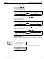
8.11 Function "simulation" (065)
⇒
If necessary, linearisation, the output signal and the current output can be tested with
the simulation function. You have the following simulation options:
Selection:
• sim. off
• sim. level
• sim. volume
• sim. current (HART only)
sim. off
Simulation is switched off.
sim. level
Enter the level value in "simulation value" (066).
The functions
• measured value (000)
• measured level (0A6)
• output current" (067) - only with HART instruments!
follow the entered values.
sim. volume
Enter the volume value in "simulation value" (066).
The functions
• measured value (000)
• output current" (067) - only with HART instruments!
follow the entered values.
sim. current (HART only)
Enter the current value in "simulation value" (066).
The function
• output current" (067) - only with HART instruments!
follows the entered values.
50
Endress+Hauser
Levelflex M
8 Function group "output" (06), - "profibus param." (06), PROFIBUS-PA only
8.12 Function "simulation value" (066)
Endress+Hauser
⇒
After selecting the "sim. level" option in the
"simulation" (065) function, the following
message appears in the display: you can enter
the level.
⇒
After selecting the "sim. volume" option in the
"simulation" (065) function, the following
message appears in the display: you can enter
the volume.
⇒
After selecting the "sim. current" option in the
"simulation" (065) function, the following
message appears in the display: Enter the output
current (only for HART instruments).
51
8 Function group "output" (06), - "profibus param." (06), PROFIBUS-PA only
Levelflex M
8.13 Function "output current" (067), HART only
⇒
Displays the output current in mA.
"
Caution!
This function is available for HART devices only!
8.14 Function "2nd cyclic value" (067),
PROFIBUS-PA only
⇒
Selects the second cyclical value.
• height/dist.
Levelflex always transmits the distance as the second cyclical value.
"
52
Caution!
This function is available for PROFIBUS-PA devices only!
Endress+Hauser
Levelflex M
8 Function group "output" (06), - "profibus param." (06), PROFIBUS-PA only
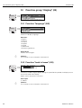
8.15 Function "4mA value" (068), HART only
⇒
In this function, enter the level (or volume, weight) at which the output current should be
4 mA. This entry is only required if you selected the "current turn down" option in the
"curr. output mode" (063) function.
8.16 Function "select v0h0" (068), PROFIBUS-PA only
⇒
Selects the value displayed in "measured value" (000).
Selection:
• measured value
• display value
measured value
The configured measured value is displayed in the "measured value" (000) function.
display value
The value in "display value" (069) is displayed in the "measured value" (000) function.
"
Endress+Hauser
Caution!
This function is available for PROFIBUS-PA devices only!
53
8 Function group "output" (06), - "profibus param." (06), PROFIBUS-PA only
Levelflex M
8.17 Function "20mA value" (069), HART only
⇒
In this function, enter the level (or volume, weight) at which the output current should be
20 mA. This entry is only required if you have selected the
"current turn down" option in the "curr. output mode" (063) function.
8.18 Function "display value" (069), PROFIBUS-PA only
⇒
This field can be set externally, e.g. from a PLC. The value is then displayed as the main
measured variable in the display by selecting the "select v0h0" (068) = "display value"
function.
"
54
Caution!
This function is available for PROFIBUS-PA devices only!
Endress+Hauser
Levelflex M
9 Function group "envelope curve" (0E)
9
Function group "envelope curve" (0E)
9.1
Function "plot settings" (0E1)
⇒
⇒
Here select which information is displayed in the LCD:
• envelope curve
• substracted signal
• mapping
9.2
Function "recording curve" (0E2)
This function defines whether the envelope curve is read as a
• single curve
or
• cyclic.
⇒
!
Endress+Hauser
Note!
If the cyclical envelope curve is active in the display, the measured variable is refreshed
in a slower cycle time. It is therefore recommended to exit the envelope curve display
after optimising the measuring point.
55
9 Function group "envelope curve" (0E)
9.3
Levelflex M
Function "envelope curve display" (0E3)
You can obtain the following information from the envelope curve display in this function:
full calibr.
quality of
evaluated echo
empty calibr.
evaluated echo
is marked
envelope curve
minimum distance
of the plot
full calibr.
distance of
evaluated echo
probe length
empty calibr.
maximum distance
of the plot
level echo
mapping
empty calibr.
level echo
substracted signal
probe length
Navigation in the envelope curve display
Using navigation, the envelope curve can be scaled horizontally and vertically and shifted to the left or the right. The active navigation mode is indicated by a symbol in the
top left hand corner of the display.
Horizontal Zoom mode:
- horizontal zoom in
- horizontal zoom out
Move mode:
- moved to the left
- moved to the right
Vertical Zoom mode:
…
56
- vertical zoom (4 steps)
Endress+Hauser
Levelflex M
9 Function group "envelope curve" (0E)
Horizontal-Zoom-Modus
Press O or S, to switch to the envelope curve navigation. You are then in Horizontal
Zoom mode. Either
or
is displayed.
You now have the following options:
• O increases the horizontal scale.
• S decreases the horizontal scale.
S
O
Move-Modus
Then press F, to switch to Move mode. Either
You now have the following options:
• O shifts the curve to the right.
• S shifts the curve to the left.
S
or
O
Vertical-Zoom-Modus
Press F, once more to switch to Vertical Zoom mode
You now have the following options:
• O increases the vertical scale.
• S decreases the vertical scale.
The display icon shows the current zoom factor (
to
S
is displayed.
is displayed.
).
O
Exiting the navigation
• Press F again to run through the different modes of the envelope curve navigation.
Press O and S to exit the navigation. The set increases and shifts are retained. Only
when you reactivate the "recording curve" (0E2) function does the Levelflex use the
standard display again.
⇒
⇓
Endress+Hauser
After 3 s, the following message appears
57
10 Function group "display" (09)
10
Levelflex M
Function group "display" (09)
⇒
10.1 Function "language" (092)
⇒
Selects the display language.
Selection:
• English
• Deutsch
• Français
• Español
• Italiano
• Nederlands
• Katakana (japanese)
Dependence
All texts are changed.
"
Caution!
This function is not visualised in Commuwin II!
10.2 Function "back to home" (093)
⇒
If no entry is made using the display during the specified time period, the display returns
to the measured value display.
9999 s means that there is no return.
User input:
3...9999 s
"
58
Caution!
This function is not visualised in Commuwin II!
Endress+Hauser
Levelflex M
10 Function group "display" (09)
10.3 Function "format display" (094)
⇒
Selects the display format.
Selection:
• decimal
• ft-in-1/16"
decimal
The measured value is given in decimal form in the display (e.g. 10.70%).
ft-in-1/16"
The measured value is given in the display in this format (e.g 5'05-14/16").
This option is only possible for "distance unit" (0C5) - "ft" and "in"!
"
Caution!
This function is not visualised in Commuwin II!
10.4 Function "no.of decimals" (095)
⇒
Selection:
•x
• x.x
• x.xx
• x.xxx
10.5 Function "sep. character" (096)
⇒
Selection:
•.
•,
.
The decimal place is separated by a point.
,
The decimal place is separated by a comma.
Endress+Hauser
59
10 Function group "display" (09)
Levelflex M
10.6 Function "display test" (097)
⇒
All display pixels are switched on. If the whole LCD is dark, it is working correctly.
⇒
⇓
60
After 3 s, the following message appears
Endress+Hauser
Levelflex M
11 Function group "diagnostics" (0A)
11
Function group "diagnostics" (0A)
⇒
In the "diagnostics" function group, you can display and confirm error messages.
Type of error
Errors that occur during commissioning or measuring are displayed immediately on the
local display. If two or more system or process errors occur, the error with the highest
priority is the one shown on the display.
The measuring system distinguishes between two types of error:
• A (Alarm):
Instrument goes into a defined state (e.g. MAX)
Indicated by a constant symbol.
(For a description of the codes, see Table 15.2 on Page 74)
• W (Warning):
Instrument continue measuring, error message is displayed.
Indicated by a flashing symbol.
(For a description of the codes, see Table 15.2 on Page 74)
• E (Alarm / Warning):
Configurable (e.g. loss of echo, level within the safety distance)
Indicated by a constant/flashing symbol.
(For a description of the codes, see Table 15.2 on Page 74)
Error messages
Error messages appear as four lines of plain text on the display. In addition, a unique
error code is also output. A description of the error codes is given on Page 74.
• The "diagnostics (0A)" function group can display current errors as well as the last
errors that occurred.
• If several current errors occur, use O or S to page through the error messages.
• The last occurring error can be deleted in the "diagnostics (0A)" function group
with the funktion"clear last error" (0A2).
Endress+Hauser
61
11 Function group "diagnostics" (0A)
Levelflex M
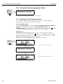
11.1 Function "present error" (0A0)
⇒
The present error is shown using this function.
11.2 Function "previous error" (0A1)
⇒
The last error presented is shown with this function.
11.3 Function "clear last error" (0A2)
⇒
Selection:
• keep
• erase
62
Endress+Hauser
Levelflex M
11 Function group "diagnostics" (0A)
11.4 Function "reset" (0A3)
"
Caution!
A reset sets the instrument back to the factory settings. This can lead to an impairment
of the measurement. Generally, you should perform a basic setup again following a
reset.
A reset is only necessary:
• if the instrument no longer functions
• if the instrument must be moved from one measuring point to another
• if the instrument is being de-installed /put into storage/installed
⇒
Entry ("reset" (0A3)):
• 333 = customer parameters (HART)
• 33333 = customer parameters (PROFIBUS-PA and Foundation Fieldbus)
333 = reset customer parameters for HART
33333 = reset customer parameters for PROFIBUS-PA and Foundation Fieldbus
This reset is recommended whenever an instrument with an unknown 'history' is to be
used in an application:
• The Levelflex is reset to the default values.
• The customer specific tank map is not deleted.
• A linearisation is switched to "linear" although the table values are retained. The table
can be reactivated in the "linearisation" (04) function group.
List of functions that are affected by a reset:
•
•
•
•
•
•
•
•
•
•
•
•
•
•
•
•
•
tank properties (002)
medium cond. (003)
process proper. (004)
empty calibr. (005)
full calibr. (006)
output on alarm (010)
output on alarm (011)
outp. echo loss (012)
ramp %span/min (013)
delay time (014)
safety distance (015)
in safety dist. (016)
overspill protection (018)
end of probe (030)
level/ullage (040)
linearisation (041)
customer unit (042)
•
•
•
•
•
•
•
•
•
•
•
•
•
•
•
•
•
max. scale (046)
diameter vessel (047)
check distance (051)
range of mapping (052)
start mapping (053)
offset (057)
output damping (058)
low output limit (062)
curr. output mode (063)
fixed cur. value (064)
4mA value (068)
language (092)
back to home (093)
format display (094)
no of decimals (095)
sep. character (096)
unlock parameter (0A4)
The mapping can also be deleted in the "cust. tank map" (055) function of the
"extended calibr." (05) function group.
A complete “basic setup" (00) must be activated.
Endress+Hauser
63
11 Function group "diagnostics" (0A)
Levelflex M
11.5 Function "unlock parameter" (0A4)
⇒
Set-up can be locked and unlocked with this function.
11.5.1 Locking of the configuration mode
The Levelflex can be protected in two ways against unauthorised changing of
instrument data, numerical values or factory settings:
"unlock parameter" (0A4):
A value <> 100 for HART (e.g. 99) or <> 2457 for PROFIBUS-PA and Foundation
Fieldbus (e.g. 2456) must be entered in "unlock parameter" (0A4) in the
"diagnostics" (0A) function group. The lock is shown on the display by the symbol
and can be released again either via the display or by communication.
Hardware lock:
The instrument is locked by pressing the O and S and F keys at the same time.
The lock is shown on the display by the symbol and can only be unlocked again
via the display by pressing the O and S and F keys at the same time again. It is not
possible to unlock the hardware by communication.
All parameters can de displayed even if the instrument is locked.
⇒
⇓
O and S and F press simultaneous
⇓
The LOCK_SYMBOL appears on the LCD.
64
Endress+Hauser
Levelflex M
11 Function group "diagnostics" (0A)
11.5.2 Unlocking of configuration mode
If an attempt is made to change parameters when the instrument is locked, the user is
automatically requested to unlock the instrument:
"unlock parameter" (0A4):
By entering the unlock parameter (on the display or via communication)
100 = for HART devices
2457 = for PROFIBUS-PA and Foundation Fieldbus devices
the Levelflex is released for operation.
Hardware-lock:
After pressing the O and S and F keys at the same time, the user is asked to enter the
unlock parameter
100 = for HART devices
2457 = for PROFIBUS-PA and Foundation Fieldbus devices.
⇒
O and S and F press simultaneous
⇓
Please enter unlock code and confirm with F.
⇓
"
Caution!
Changing certain parameters such as all sensor characteristics, for example, influences
numerous functions of the entire measuring system, particularly measuring accuracy.
There is no need to change these parameters under normal circumstances and
consequently, they are protected by a special code known only to the E+H service
organization. Please contact Endress+Hauser if you have any questions.
11.6 Function "measured dist." (0A5)
⇒
Display of measured distance in the selected "distance unit" (0C5).
Endress+Hauser
65
11 Function group "diagnostics" (0A)
Levelflex M
11.7 Function "measured level" (0A6)
⇒
Display of measured level in the selected "distance unit" (0C5).
20 mA
100%
measured dist.(0A5)
measured level (0A6)
4 mA
0%
11.8 Function "application par." (0A8)
⇒
Displays whether or not one of the settings dependent on the "tank shape" (002),
"medium property" (003) and "process cond." (004) application parameters has been
changed or not.
If, for example, the "output damping" (058) is changed, the
"application par." shows "modified".
Selection:
• not modified
• modified
⇒
⇓
66
After 3 s, the following message appears
Endress+Hauser
Levelflex M
12 Function group "system parameters" (0C)
12
Function group "system parameters" (0C)
⇒
12.1 Function "tag no." (0C0)
⇒
You can define the tag number with this function.
User input:
• 16 alphanumeric characters for HART instruments (8 using the HART universal
command)
• 32 alphanumeric characteristics for PROFIBUS-PA instruments
12.2 Function "device tag" (0C0), Foundation
Fieldbus only
This function displays the tag number.
12.3 Function "Profile Version" (0C1),
PROFIBUS-PA only
⇒
The PA Profile version is shown using this function (Profile 3.0).
"
Caution!
This function is available for PROFIBUS-PA devices only!
12.4 Function "protocol+sw-no." (0C2)
⇒
This function shows the protocol and the hardware and software version: Vxx.yy.zz.prot.
Display:
xx: hw-version
yy: sw-version
zz: sw-revision
prot: protocoll type (e.g. HART)
Endress+Hauser
67
12 Function group "system parameters" (0C)
Levelflex M
12.5 Function "serial no." (0C4)
⇒
This function displays the instrument serial number.
12.6 Function "device id" (0C4), Foundation
Fieldbus only
This function displays the instrument serial number.
12.7 Function "distance unit" (0C5)
⇒
You can select the basic distance unit with this function.
Selection:
•m
• ft
• mm
• inch
Dependence
m, mm: "format display" (094) can only be "decimal".
The units are changed for the following parameters:
• empty calibr. (005)
• full calibr. (006)
• safety distance (015)
• input level (044)
• diameter vessel (047)
• range of mapping (052)
• cust. tank map (055)
• offset (057)
• simulation value (066)
• measured dist. (0A5)
• measured level(0A6)
68
Endress+Hauser
Levelflex M
12 Function group "system parameters" (0C)
12.8 Function "download mode" (0C8)
⇒
This parameter defines which values are written to the instrument during a ToF Tool or
Commuwinn II configuration download.
Selection:
• parameter only
• param+cust.map
• mapping only
!
Note!
This parameter must not be described explicitly in ToF Tool. The various possibilities
can be selected from the download dialog.
⇒
⇓
Endress+Hauser
After 3 s, the following message appears
69
13 Function group "service" (0D)
13
Levelflex M
Function group "service" (0D)
You can find a detailed description of the "Service" function group as well as a detailed
overview of the function menu in the Service Manual for Levelflex M.
70
Endress+Hauser
Levelflex M
14 Envelope curve
14
Envelope curve
14.0.1 Envelope curve with the ToF Tool
Signal analysis via envelope curve
See page 55 ff. for the envelope curve in the local display.
Endress+Hauser
71
15 Trouble-shooting
Levelflex M
15
Trouble-shooting
If you have followed the instructions in this operating manual, the Levelflex should work
correctly. If this is not the case, Levelflex has facilities for analysing and correcting
errors.
You can find a structured approach for locating errors on page 73 ff. or in the appropriate instrument operating manual.
72
Endress+Hauser
Levelflex M
15 Trouble-shooting
15.1 Trouble-shooting instructions
Levelflex M -Trouble Shooting
Check voltage and
compare it with the
specifications on the
nameplate.
Instrument does
not respond
Not ok
Connect the
correct voltage
Yes
Instrument works?
Ready
No
ok
Check the polarity
of the voltage.
Not ok
Correct the polarity
Yes
Instrument works?
Ready
No
ok
Check power connection
to electronic board
Not ok
Connect plug
Yes
Instrument works?
Ready
No
ok
Values on display
invissible
Yes
Contrast:
F+ O
ok
Ready
Not ok
No
Check plug contact
of the display.
Not ok
Connect the plug
correctly
Yes
Ready
Display works?
No
ok
Output current between
3.6 …22mA ?
Yes
The display is possibly defective.
Contact E+H Service
No
Output current
< 3.6 mA ? (2 wire)
< 2.4 mA ? (4 wire)
Yes
Check cabling
Not ok
Correct the
cabling
Yes
Current is ok?
Ready
No
ok
Possibly defective electronics
Contact E+H Service
HART
communication
does not
function
Yes
Is the communication
resistor installed
according to the
OM?
Not ok
Install the fuse
(see the OM)
Communication ok?
Yes
Ready
No
ok
Is the Commubox
connected according
to the OM?
Not ok
Connect the
Commubox
(see the OM)
Communication ok?
Yes
Ready
No
ok
Is the switch on the
Commubox for
selecting HART/Intensor
in the correct position?
Not ok
Set the switch
correctly
Yes
Communication ok?
ok
Communication
PA does not
function
Yes
Check cabling +
terminator
Ready
No
Contact E+H Service
Not ok
Correct cabling +
terminator
Yes
Ready
Communication ok?
No
ok
Yes
EMC interference?
Check screening
(see BA Section
'Connection’)
Yes
Communication ok?
Ready
No
No
Contact E+H Service
Communication
via Service adapter
FXA 193 does not
function
Yes
Check configuration
of COM port on PC
Not ok
Correct configuration
Communication ok?
Yes
Ready
No
Contact E+H Service
Instrument
measures
incorrectly
Yes
Check basic setup
ok
Not ok
Repeat
basic setup
Measurement ok?
Yes
Ready
No
Proceed according
to section
'Trouble shooting’ in OM
Endress+Hauser
73
15 Trouble-shooting
Levelflex M
15.2 System error messages
Code
Description
Possible cause
Remedy
A102
checksum error
general reset & new
calibr.required
device has been powered off
before data could be stored; emc
problem; E²PROM defect
reset;
avoid emc problem; if alarm
prevails after reset, exchange
electronics
W103
initialising - please
wait
E²PROM storage not yet finished
wait some seconds; if
warning prevails, exchange
electronics
A106
downloading please
wait
processing data download
wait until warning disappears
A110
checksum error
general reset & new
calibr.required
device has been powered off
before data could be stored; emc
problem; E²PROM defect
reset;
avoid emc problem; if alarm
prevails after reset, exchange
electronics
A111
electronics defect
RAM defective
reset;
if alarm prevails after reset,
exchange electronics
A113
electronics defect
ROM defective
reset;
if alarm prevails after reset,
exchange electronics
A114
electronics defect
E2PROM defective
reset;
if alarm prevails after reset,
exchange electronics
A115
electronics defect
general hardware problem
reset;
if alarm prevails after reset,
exchange electronics
A116
download error
repeat download
checksum of stored data not
correct
restart download of data
A121
electronics defect
no factory calibration existant;
E²PROM defective
contact service
W153
initialising - please
wait
initialisation of electronics
wait some seconds; if
warning prevails, power off
device and power on again
A160
checksum error
general reset & new
calibr.required
device has been powered off
before data could be stored; emc
problem; E²PROM defect
reset;
avoid emc problem; if alarm
prevails after reset, exchange
electronics
A164
electronics defect
hardware problem
reset;
if alarm prevails after reset,
exchange electronics
A171
electronics defect
hardware problem
reset;
if alarm prevails after reset,
exchange electronics
A221
Probe pulse deviation
from average values
HF module or cable between HF
module and electronics defective
Check contacts on
HF module
If fault cannot be eliminated:
Replace HF module
Tab. 3
74
System error messages
Endress+Hauser
Levelflex M
15 Trouble-shooting
Code
Description
Possible cause
Remedy
A241
Broken probe
Broken probe or
value for probe length is too short
Check the probe length in
033, Check the probe itself,
if the probe is broken,
change the probe, or change
to a non contact system
A251
Feedthrough
Lost contact in the process
feedthrough
Replace process feedtrough
A261
HF cable defective
HF cable defective or HF
connector removed
Check HF connector, replace
cable if defective
A275
Offset too high
Temperature at the electronics too
high or HF module defective
Check temperature, replace
HF module if defective
A512
recording of mapping
please wait
mapping active
wait some seconds until
alarm disappears
W601
linearisation ch1 curve
not monotone
linearization not monotonously
increasing
correct linearisation table
W611
less than 2
linearisation points for
channel 1
number of entered linearization
points < 2
correct linearisation table
W621
simulation ch. 1 on
simulation mode is active
switch off simulation mode
E641
no usable echo
channel 1
check calibr.
echo lost due to application
conditions of built up on antenna
check installation; clean
antenna (cf. Operating
Instructions)
E651
level in safety
distance - risk of
overspill
level in safety distance
alarm will disappear as soon
as level leaves safety
distance;
A671
linearisation ch1 not
complete, not usable
linearisation table is in edit mode
activate linearisation table
W681
current ch1 out of
range
current out of range (3,8 mA ... 21,5
mA)
check calibration and
linearisation
Tab. 3
Endress+Hauser
System error messages
75
15 Trouble-shooting
Levelflex M
15.3 Application errors
Error
Output
Possible cause
Remedy
A warning or
alarm has
occurred.
Depending on the configuration
See table of
error messages
(see page 74)
1. See table of error messages
(see page 74)
Measured distance
(008) OK?
D m/ft (008)
Measured value
(00) is incorrect
F m/ft
yes → 1. Check empty calibr. (005) and
full calibr. (006).
2. Check linearisation:
→ level/ullage (040)
→ max. scale (046)
→ diameter vessel (047)
→ Check table
20 mA/100%
expected
no ↓
actual
E m/ft
t→
4 mA/0%
No change off
measured value
on
filling/emptying
20 mA/100%
An interference echo
may have been
evaluated.
yes → 1. Carry out tank mapping
→ basic setup
Interference echo
from
installations, nozzle
or extension on the
antenna
1. Carry out tank mapping
→ basic setup
noise level during the
initialisation phase to
high.
Repeat once more empty calibr. (005).
Caution!
Before conformation change with
O or S to the edit mode.
2. If necessary, clean probe.
3. If necessary, select better
mounting position
actual
expected
4 mA/0%
E 641 (loss of
echo) after turn
on the power
supply
76
t→
If the instrument is configured to Hold by
loss of echo the output is set to any
value/current.
Endress+Hauser
Levelflex M
15 Trouble-shooting
Device displays a
level when the
tank is empty.
Incorrect probe
length
1. Carry out automatic probe length
detection when the tank is empty.
2. Carry out mapping over entire probe
when the tank is empty (probe free).
Tank properties incorrect.
LN < 4 mm and "Aluminium tank" tank
properties selected
→ Calibration not possible.
→ Selection
→ Select standard
→ Thresholds too high
Medium properties
incorrect.
Select lower medium properties.
20 mA/100%
actual
expected
t→
4 mA/0%
Measured value
incorrect (slope
error in the entire
measuring range)
20 mA/100%
expected
2.) actual
1.) actual
4 mA/0%
Endress+Hauser
t→
77
15 Trouble-shooting
78
Levelflex M
Endress+Hauser
Index function menu
Levelflex M
Index function menu
Function group
00 = basic setup . . . . . . . . . . . . . . . . . . . . . . . . . . . .
01 = safety settings. . . . . . . . . . . . . . . . . . . . . . . . . .
03 = length adjustment . . . . . . . . . . . . . . . . . . . . . . .
04 = linearisation. . . . . . . . . . . . . . . . . . . . . . . . . . . .
05 = extended calibr. . . . . . . . . . . . . . . . . . . . . . . . .
06 = output . . . . . . . . . . . . . . . . . . . . . . . . . . . . . . . .
06 = Profibus Param. (PROFIBUS-PA only) . . . . . . .
0E = envelope curve . . . . . . . . . . . . . . . . . . . . . . . . .
09 = display . . . . . . . . . . . . . . . . . . . . . . . . . . . . . . .
0A = diagnostics . . . . . . . . . . . . . . . . . . . . . . . . . . . .
0C = system parameter . . . . . . . . . . . . . . . . . . . . . .
14
23
30
32
40
45
45
55
58
61
67
Function
000 = measured value . . . . . . . . . . . . . . . . . . . . . . .
002 = tank properties . . . . . . . . . . . . . . . . . . . . . . . .
003 = medium property . . . . . . . . . . . . . . . . . . . . . .
004 = process propert.. . . . . . . . . . . . . . . . . . . . . . .
005 = empty calibr. . . . . . . . . . . . . . . . . . . . . . . . . . .
006 = full calibr. . . . . . . . . . . . . . . . . . . . . . . . . . . . .
010 = output on alarm. . . . . . . . . . . . . . . . . . . . . . . .
011 = output on alarm (HART only) . . . . . . . . . . . . .
012 = outp. echo loss . . . . . . . . . . . . . . . . . . . . . . . .
013 = ramp %span/min. . . . . . . . . . . . . . . . . . . . . . .
014 = delay time . . . . . . . . . . . . . . . . . . . . . . . . . . . .
015 = safety distance . . . . . . . . . . . . . . . . . . . . . . . .
016 = in safety dist.. . . . . . . . . . . . . . . . . . . . . . . . . .
017 = ackn. alarm . . . . . . . . . . . . . . . . . . . . . . . . . . .
018 = overspill prot. . . . . . . . . . . . . . . . . . . . . . . . . .
019 = brocken probe det . . . . . . . . . . . . . . . . . . . . .
030 = end of probe. . . . . . . . . . . . . . . . . . . . . . . . . .
031 = probe length. . . . . . . . . . . . . . . . . . . . . . . . . .
032 = probe. . . . . . . . . . . . . . . . . . . . . . . . . . . . . . . .
033 = probe length. . . . . . . . . . . . . . . . . . . . . . . . . .
034 = determine length. . . . . . . . . . . . . . . . . . . . . . .
040 = level/ullage.. . . . . . . . . . . . . . . . . . . . . . . . . . .
041 = linearisation. . . . . . . . . . . . . . . . . . . . . . . . . . .
042 = customer unit . . . . . . . . . . . . . . . . . . . . . . . . .
043 = table no. . . . . . . . . . . . . . . . . . . . . . . . . . . . . .
044 = input level . . . . . . . . . . . . . . . . . . . . . . . . . . . .
045 = input volume . . . . . . . . . . . . . . . . . . . . . . . . . .
046 = max. scale. . . . . . . . . . . . . . . . . . . . . . . . . . . .
047 = diameter vessel. . . . . . . . . . . . . . . . . . . . . . . .
050 = Selection . . . . . . . . . . . . . . . . . . . . . . . . . . . . .
051 = check distance . . . . . . . . . . . . . . . . . . . . . . . .
052 = range of mapping . . . . . . . . . . . . . . . . . . . . . .
053 = start mapping . . . . . . . . . . . . . . . . . . . . . . . . .
054 = pres. Map dist. . . . . . . . . . . . . . . . . . . . . . . . .
055 = delete mapping. . . . . . . . . . . . . . . . . . . . . . . .
79
14
14
15
16
18
18
23
25
25
26
27
27
27
29
29
29
30
30
30
31
31
32
33
37
38
38
39
39
39
40
40
41
41
42
42
056 = echo quality . . . . . . . . . . . . . . . . . . . . . . . . . .
058 = output damping . . . . . . . . . . . . . . . . . . . . . . .
059 = upper block.dist . . . . . . . . . . . . . . . . . . . . . . .
060 = commun.address (HART only) . . . . . . . . . . .
060 = instrument addr. (PROFIBUS-PA only) . . . . .
061 = no. of preambels (HART only) . . . . . . . . . . . .
061 = ident number (PROFIBUS-PA only) . . . . . . . .
062 = low output limit (HART only). . . . . . . . . . . . . .
062 = set unit to bus (PROFIBUS-PA only) . . . . . . .
063 = curr. output mode (HART only) . . . . . . . . . . .
063 = out value (PROFIBUS-PA only) . . . . . . . . . . .
064 = fixed cur. value (HART only) . . . . . . . . . . . . .
064 = out status (PROFIBUS-PA only) . . . . . . . . . . .
065 = simulation. . . . . . . . . . . . . . . . . . . . . . . . . . . .
066 = simulation value . . . . . . . . . . . . . . . . . . . . . . .
067 = output current (HART only) . . . . . . . . . . . . . .
067 = 2nd cyclic value (PROFIBUS-PA only) . . . . .
068 = 4mA value (HART only) . . . . . . . . . . . . . . . . .
068 = select v0h0 (PROFIBUS-PA only) . . . . . . . . .
069 = 20mA value (HART only) . . . . . . . . . . . . . . . .
069 = display value (PROFIBUS-PA only) . . . . . . . .
092 = language . . . . . . . . . . . . . . . . . . . . . . . . . . . .
093 = back to home . . . . . . . . . . . . . . . . . . . . . . . . .
094 = format display . . . . . . . . . . . . . . . . . . . . . . . .
095 = no.of decimals . . . . . . . . . . . . . . . . . . . . . . . .
096 = sep. character . . . . . . . . . . . . . . . . . . . . . . . .
097 = display test. . . . . . . . . . . . . . . . . . . . . . . . . . .
0A0 = present error . . . . . . . . . . . . . . . . . . . . . . . . .
0A1 = previous error . . . . . . . . . . . . . . . . . . . . . . . .
0A2 = clear last error . . . . . . . . . . . . . . . . . . . . . . . .
0A3 = reset . . . . . . . . . . . . . . . . . . . . . . . . . . . . . . .
0A4 = unlock parameter . . . . . . . . . . . . . . . . . . . . .
0A5 = measured dist.. . . . . . . . . . . . . . . . . . . . . . . .
0A6 = measured level . . . . . . . . . . . . . . . . . . . . . . .
0A8 = application par. . . . . . . . . . . . . . . . . . . . . . . .
0C0 = tag no. . . . . . . . . . . . . . . . . . . . . . . . . . . . . . .
0C0 = device tag (Foundation Fieldbus only) . . . . .
0C1 = Profile Version (PROFIBUS-PA only) . . . . . . .
0C2 = protocoll+sw-no. . . . . . . . . . . . . . . . . . . . . . .
0C4 = serial no. . . . . . . . . . . . . . . . . . . . . . . . . . . . .
0C4 = device id. (Foundation Fieldbus only) . . . . . .
0C5 = distance unit . . . . . . . . . . . . . . . . . . . . . . . . .
0C8 = download mode . . . . . . . . . . . . . . . . . . . . . .
0E1 = plot settings . . . . . . . . . . . . . . . . . . . . . . . . . .
0E2 = recording curve . . . . . . . . . . . . . . . . . . . . . . .
0E3 = envelope curve display . . . . . . . . . . . . . . . . .
D00 = service level . . . . . . . . . . . . . . . . . . . . . . . . .
43
44
44
45
45
46
46
47
47
48
48
49
49
50
51
52
52
53
53
54
54
58
58
59
59
59
60
62
62
62
63
64
65
66
66
67
67
67
67
68
68
68
69
55
55
56
70
Endress+Hauser
Europe
Austria
Endress+Hauser Ges.m.b.H.
Wien
Tel. (01) 88056-0, Fax (01) 88056-35
Belarus
Belorgsintez
Minsk
Tel. (0172) 508473, Fax (0172) 508583
Belgium / Luxembourg
Endress+Hauser N.V.
Brussels
Tel. (02) 2480600, Fax (02) 2480553
Bulgaria
INTERTECH-AUTOMATION
Sofia
Tel. (02) 664869, Fax (02) 9631389
Croatia
Endress+Hauser GmbH+Co.
Zagreb
Tel. (01) 6637785, Fax (01) 6637823
Cyprus
I+G Electrical Services Co. Ltd.
Nicosia
Tel. (02) 484788, Fax (02) 484690
Czech Republic
Endress+Hauser GmbH+Co.
Praha
Tel. (026) 6784200, Fax (026) 6784179
Denmark
Endress+Hauser A/S
Søborg
Tel. (70) 131132, Fax (70) 132133
Estonia
ELVI-Aqua
Tartu
Tel. (7) 441638, Fax (7) 441582
Finland
Endress+Hauser Oy
Helsinki
Tel. (0204) 83160, Fax (0204) 83161
France
Endress+Hauser S.A.
Huningue
Tel. (389) 696768, Fax (389) 694802
Germany
Endress+HauserMesstechnik GmbH+Co.
Weil am Rhein
Tel. (07621) 975-01, Fax (07621) 975-555
Great Britain
Endress+Hauser Ltd.
Manchester
Tel. (0161) 2865000, Fax (0161) 9981841
Greece
I & G Building Services Automation S.A.
Athens
Tel. (01) 9241500, Fax (01) 9221714
Hungary
Mile Ipari-Elektro
Budapest
Tel. (01) 4319800, Fax (01) 4319817
Iceland
BIL ehf
Reykjavik
Tel. (05) 619616, Fax (05) 619617
Ireland
Flomeaco Company Ltd.
Kildare
Tel. (045) 868615, Fax (045) 868182
Italy
Endress+Hauser S.p.A.
Cernusco s/N Milano
Tel. (02) 92192-1, Fax (02) 92192-362
Latvia
Rino TK
Riga
Tel. (07) 315087, Fax (07) 315084
Lithuania
UAB "Agava"
Kaunas
Tel. (07) 202410, Fax (07) 207414
Netherlands
Endress+Hauser B.V.
Naarden
Tel. (035) 6958611, Fax (035) 6958825
Bolivia
Tritec S.R.L.
Cochabamba
Tel. (042) 56993, Fax (042) 50981
Pakistan
Speedy Automation
Karachi
Tel. (021) 7722953, Fax (021) 7736884
Norway
Endress+Hauser A/S
Tranby
Tel. (032) 859850, Fax (032) 859851
Brazil
Samson Endress+Hauser Ltda.
Sao Paulo
Tel. (011) 50313455, Fax (011) 50313067
Philippines
Endress+Hauser Philippines Inc.
Metro Manila
Tel. (2) 3723601-05, Fax (2) 4121944
Poland
Endress+Hauser Polska Sp. z o.o.
Wroclaw
Tel. (022) 7803723, Fax (022) 7803760
Canada
Endress+Hauser Ltd.
Burlington, Ontario
Tel. (905) 6819292, Fax (905) 6819444
Singapore
Endress+Hauser (S.E.A.) Pte., Ltd.
Singapore
Tel. 5668222, Fax 5666848
Portugal
Tecnisis - Tecnica de Sistemas Industriais
Linda-a-Velha
Tel. (21) 4267290, Fax (21) 4267299
Chile
Endress+Hauser Chile Ltd.
Santiago
Tel. (02) 321-3009, Fax (02) 321-3025
South Korea
Endress+Hauser (Korea) Co., Ltd.
Seoul
Tel. (02) 6587200, Fax (02) 6592838
Romania
Romconseng S.R.L.
Bucharest
Tel. (01) 4101634, Fax (01) 4112501
Colombia
Colsein Ltda.
Bogota D.C.
Tel. (01) 2367659, Fax (01) 6104186
Taiwan
Kingjarl Corporation
Taipei R.O.C.
Tel. (02) 27183938, Fax (02) 27134190
Russia
Endress+Hauser Moscow Office
Moscow
Tel. (095) 1587564, Fax (095) 1589871
Costa Rica
EURO-TEC S.A.
San Jose
Tel. (02) 961542, Fax (02) 961542
Thailand
Endress+Hauser Ltd.
Bangkok
Tel. (2) 9967811-20, Fax (2) 9967810
Slovakia
Transcom Technik s.r.o.
Bratislava
Tel. (7) 44888684, Fax (7) 44887112
Ecuador
Insetec Cia. Ltda.
Quito
Tel. (02) 269148, Fax (02) 461833
Vietnam
Tan Viet Bao Co. Ltd.
Ho Chi Minh City
Tel. (08) 8335225, Fax (08) 8335227
Slovenia
Endress+Hauser D.O.O.
Ljubljana
Tel. (01) 5192217, Fax (01) 5192298
Guatemala
ACISAAutomatizacionYControlIndustrial S.A.
Ciudad de Guatemala, C.A.
Tel. (03) 345985, Fax (03) 327431
Iran
PATSA Co.
Tehran
Tel. (021) 8754748, Fax(021) 8747761
Spain
Endress+Hauser S.A.
Sant Just Desvern
Tel. (93) 4803366, Fax (93) 4733839
Mexico
Endress+Hauser S.A. de C.V.
Mexico City
Tel. (5) 5682405, Fax (5) 5687459
Israel
Instrumetrics Industrial Control Ltd.
Tel-Aviv
Tel. (09) 8357090, Fax (09) 8350619
Sweden
Endress+Hauser AB
Sollentuna
Tel. (08) 55511600, Fax (08) 55511655
Paraguay
Incoel S.R.L
.Asuncion
Tel. (021) 213989, Fax (021) 226583
Jordan
A.P. Parpas Engineering S.A.
Amman
Tel. (06) 4643246, Fax (06) 4645707
Switzerland
Endress+Hauser Metso AG
Reinach/BL 1
Tel. (061) 7157575, Fax (061) 7111650
Uruguay
Circular S.A.
Montevideo
Tel. (02) 925785, Fax (02) 929151
Kingdom of Saudi Arabia
Anasia Ind. Agencies
Jeddah
Tel. (02) 6710014, Fax (02) 6725929
Turkey
Intek Endüstriyel Ölcü ve Kontrol SistemleriIstanbul
Tel. (0212) 2751355, Fax (0212) 2662775
USA
Endress+Hauser Inc.
Greenwood, Indiana
Tel. (317) 535-7138, Fax (317) 535-8498
Lebanon
Network Engineering
Jbeil
Tel. (3) 944080, Fax (9) 548038
Ukraine
Photonika GmbH
Kiev
Tel. (44) 26881, Fax (44) 26908
Venezuela
Controval C.A.
Caracas
Tel. (02) 9440966, Fax (02) 9444554
Sultanate of Oman
Mustafa & Sultan Sience & Industry Co. L.L.C.
Ruwi
Tel. 602009, Fax 607066
Asia
United Arab Emirates
Descon Trading EST.
Dubai
Tel. (04) 2653651, Fax (04) 2653264
China
Endress+Hauser Shanghai
Instrumentation Co. Ltd.
Shanghai
Tel. (021) 54902300, Fax (021) 54902303
Yemen
YemenCompany for Ghee and Soap Industry
Taiz
Tel. (04) 230664, Fax (04) 212338
Yugoslavia Rep.
Meris d.o.o.
Beograd
Tel.(11) 4441966, Fax (11) 4441966
Africa
Egypt
Anasia
Heliopolis/Cairo
Tel. (02) 4179007, Fax (02) 4179008
Members of the Endress+Hauser group
BA 245F/00/en/11.03
52011936
CCS / FM+SGML 6.0
Endress+Hauser Beijing Office
Beijing
Tel. (010) 68344058, Fax: (010) 68344068
Morocco
Oussama S.A.
Casablanca
Tel. (02) 241338, Fax (02) 402657
Hong Kong
Endress+Hauser HK Ltd.
Hong Kong
Tel. 25283120, Fax 28654171
South Africa
Endress+Hauser Pty. Ltd.
Sandton
Tel. (011) 26280000, Fax (011) 2628062
India
Endress+Hauser (India) Pvt. Ltd.
Mumbai
Tel. (022) 8521458, Fax (022) 8521927
Tunisia
Controle, Maintenance et Regulation
Tunis
Tel. (01) 793077, Fax (01) 788595
Indonesia
PT Grama Bazita
Jakarta
Tel. (21) 7975083, Fax (21) 7975089
America
Japan
Sakura Endress Co. Ltd.
Tokyo
Tel. (0422) 540613, Fax (0422) 550275
Argentina
Endress+Hauser Argentina S.A.
Buenos Aires
Tel. (01) 145227970, Fax (01) 145227909
http://www.endress.com
12.01/LC
Malaysia
Endress+Hauser (M) Sdn. Bhd.
Petaling Jaya, Selangor Darul Ehsan
Tel. (03) 7334848, Fax (03) 7338800
Australia + New Zealand
Australia
ALSTOM Australia Limited
Milperra
Tel. (02) 97747444, Fax (02) 97744667
New Zealand
EMC Industrial Group Limited
Auckland
Tel. (09) 4155110, Fax (09) 4155115
All other countries
Endress+Hauser GmbH+Co. KG
Instruments International
Weil am Rhein
Germany
Tel. (07621) 975-02, Fax (07621) 975-345