1
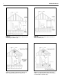
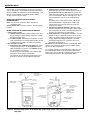
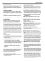
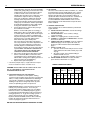
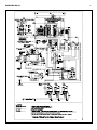
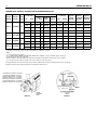
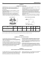
EUTECTIC EC-10
OIL-FIRED WATER BOILERS/NO. 2 OIL
INSTALLATION AND OPERATING INSTRUCTIONS
SAFETY WARNING:
KEEP BOILER AREA CLEAR AND FREE FROM COMBUSTIBLE MATERIALS, GASOLINE AND OTHER FLAMMABLE VAPORS AND LIQUIDS. FAILURE TO ADHERE TO
ABOVE SAFETY WARNING, MAY RESULT IN PERSONAL
INJURY OR DEATH AND PROPERTY DAMAGE.
CONTENTS . . . . . . . . . . . . . . . . . . . . . . . . . . . . . . . . . . . .PAGE
Ratings and Dimensions . . . . . . . . . . . . . . . . . . . . . . . . . . . . .2
Installation Requirements:
Boiler Location . . . . . . . . . . . . . . . . . . . . . . . . . . . . . . . . . . .3
Clearances . . . . . . . . . . . . . . . . . . . . . . . . . . . . . . . . . .3 & 4
Chimney Requirements . . . . . . . . . . . . . . . . . . . . . . . . . . . .3
Air Supply and Venting . . . . . . . . . . . . . . . . . . . . . . . . . . .3-7
Controls and Accessories . . . . . . . . . . . . . . . . . . . . . . . . . .7
Piping for Water Units . . . . . . . . . . . . . . . . . . . . . . . . . . . . .7
Installing Burner . . . . . . . . . . . . . . . . . . . . . . . . . . . . . . . . .8
Oil Supply Piping . . . . . . . . . . . . . . . . . . . . . . . . . . . . . . . . .8
Wiring the Boiler . . . . . . . . . . . . . . . . . . . . . . . . . . . . . . . . .8
Vent Piping and Draft Regulator . . . . . . . . . . . . . . . . . . . . .8
Operating Instructions:
Precautions Before Starting . . . . . . . . . . . . . . . . . . . . . . . .8
Start-up . . . . . . . . . . . . . . . . . . . . . . . . . . . . . . . . . . . . . . . .8
Cleaning and Filling New Water Boiler . . . . . . . . . . . . . . . .9
Care and Maintenance:
Extended Shutdown . . . . . . . . . . . . . . . . . . . . . . . . . . . . . .9
Freezing Protection . . . . . . . . . . . . . . . . . . . . . . . . . . . . . .10
Oil Burner . . . . . . . . . . . . . . . . . . . . . . . . . . . . . . . . . . . . . .10
General Maintenance . . . . . . . . . . . . . . . . . . . . . . . . . . . .10
Wiring Diagrams . . . . . . . . . . . . . . . . . . . . . . . . . . . . . . . .11-13
Burner Data . . . . . . . . . . . . . . . . . . . . . . . . . . . . . . . . . . . .14-17
Appendix A–G . . . . . . . . . . . . . . . . . . . . . . . . . . . . . . . . .18-20
IMPORTANT: The installation of this equipment must conform
to the requirements of the authority having jurisdiction or, in
the absence of such requirements, to the Installation of Oil
Burning Equipment, CSA B139, latest edition. The installation
must also conform to the additional requirements in this
Slant/Fin Instruction Manual. Where there is any difference,
the more stringent requirement shall govern.
In addition, where required by the authority having jurisdiction, the installation must conform to American Society of
Mechanical Engineers Safety Code for Controls and Safety
Devices for Automatically Fired Boilers, No. CSD-1 or CSA
B149.1-00 for natural gas and propane. If there is any conflict
in the above requirements, then the more stringent requirement will apply.
SERVICE COMPANY
Name_______________________________________________
Address _____________________________________________
____________________________________________________
Telephone ___________________________________________
THIS MANUAL MUST BE LEFT WITH OWNER AND SHOULD
BE HUNG ON OR ADJACENT TO THE BOILER FOR
REFERENCE.
IMPORTANT: This boiler must be installed, serviced and
repaired by a trained, experienced, service technician, licensed
for the installation and servicing of oil burning hot water heating
system equipment or otherwise qualified by the authorities having jurisdiction over the installation.
Model #_____________________________________________
Serial # _____________________________________________
Printed in Canada 6/10
Part No. 470900000
Publication No. EC-10-40
Rev. C
A
Rev.
EUTECTIC EC-10
2
Figure 1: Dimensions
355mm
(13-3/32)
195mm (7-11/16)
Relief valve
19mm (3/4")
835mm (32-7/8")
32mm (1-1/4")
threaded supply
289mm (1-1/8)
113mm
(4-7/16)
79mm (11-3/8)
394mm(15-1/2)
60mm (2-23/64)
32mm (1-1/4)
threaded return
pipe
156mm
(6-9/64")
138mm(5-7/16)
∅ 110mm
(4-21/64) hole
∅ 130mm
(6-7/64) cut-out
563mm(22-11/64)
(4) 3/8-16 studs
on ∅ 6-29/32 4
markings on ∅
176mm (6-15/16)
285mm (11-7/32)
163mm
(6-27/64)
570mm (22-7/16)
570mm (22-7/16)
Note: Add 203mm (8") to B dimensions to allow for Riello burner
TABLE 1: Ratings and Dimensions
OIL INPUT † §
GROSS
OUTPUT*
NET
OUTPUT*
CHIMNEY SIZE
I.D. ROUND
I.D. ROUND
X HEIGHT
mL/s GPH
Watts
BTU/H
kW
MBH
kW
MBH
EC-13A
0.68
0.65
26,672
91,000
23
79
20
69
152 x 4.6
6 x 15
EC-13B
0.74
0.70
28,724
98,000
25
85
22
74
152 x 4.6
6 x 15
.
AFUE %
BOILER
MODEL
NO.
mm x m (in X ft.)
APPROX.
OVERALL
LENGTH
BOILER
LENGTH
"A"
DIMENSIONS
BOILER
LENGTH
"B"
.
FLUE DIA
"C"
FLUE
DISTANCE BETWEEN
OUTLET
LEGS
LENGTH
"D"
"E"
"F"
mm
in
mm
in.
mm
in.
mm
(in.)
mm
in.
mm
87
914
36
25
22-1/4
686
27
127
5
300
11-13/16
51
in.
2
86
914
36
25
22-1/4
686
27
127
5
300
11-13/16
51
2
EC-14A
0.84
0.80
32,827 112,000
29
98
25
85
152 x 4.6
6 x 15
87
1041
41
686
27
813
32
127
5
427
16-13/16
51
2
EC-14B
0.95
0.90
36,931 126,000
32
109
28
95
152 x 4.6
6 x 15
86
1041
41
686
27
813
32
127
5
427
16-13/16
51
2
EC-15A
1.05
1.00
41,034 140,000
36
123
31
107
152 x 4.6
6 x 15
87
1168
46
819
32-1/4
940
37
127
5
554
21-13/16
51
2
EC-15B
1.16
1.10
45,137 154,000
39
134
34
117
152 x 4.6
6 x 15
86
1168
46
819
32-1/4
940
37
127
5
554
21-13/16
51
2
EC-16A
1.21
1.15
47,189 161,000
41
141
36
123
152 x 4.6
6 x 15
87
1295
51
946
37-1/4
1067
42
152
6
681
26-13/16 102
4
EC-16B
1.32
1.25
51,293 175,000
45
152
39
132
152 x 4.6
6 x 15
86
1295
51
946
37-1/4
1067
42
152
6
681
26-13/16 102
4
Maximum operating pressure 414 kPa (60 psi).
All boilers hydrostatically tested — A.S.M.E.
* For forced hot water heating systems where the boiler and all piping are located
within the area to be heated, the boiler may be selected on the basis of net
capacity output. The net output ratings shown are based on an allowance for
piping and pickup of 1.15 (water). Gross capacity output is divided by the
allowance to obtain net rating. The Slant/Fin Technical Service department
should be consulted before selecting a boiler for unusual piping and pickup
requirements such as intermittent system operation, extensive piping, etc.
† Ratings apply to the use of light oil at 11 000 W/L (140,000 Btu per gallon) and
apply only when burner models listed on pages 13 and 16 of this manual are
used, and are properly adjusted to produce 13% CO2.
§ Boiler models have two firing rates. The boiler is factory shipped at the lower
firing rate. To obtain the higher firing rate, refer to the boiler installation
instructions for the appropriate field adjustments.
# All dimensions subject to normal manufacturing tolerance.
NOTE: All boilers under 87.9 kW (300,000 Btuh) input are tested and certified for
A.F.U.E. capacities.
EUTECTIC EC-10
3
THE INSTALLATION INSTRUCTIONS IN THIS MANUAL ARE
ABBREVIATED. SEE THE FRONT COVER OF THIS MANUAL
FOR REFERENCES TO CODES AND STANDARDS.
BOILER LOCATION
CAUTION: NEVER BURN GARBAGE OR PAPER IN THE UNIT,
AND NEVER LEAVE COMBUSTIBLE MATERIAL AROUND IT.
Provide a level, solid foundation for the boiler. Location should
be near the chimney so that the Flue Pipe Connector or
Breeching to the chimney is short and direct.
A. The foundation must be capable of supporting the weight of
the boiler when filled with water:
Boiler
Size
EC-13
EC-14
EC-15
EC-16
Approximate Total Weight of Boiler
Assembly*, filled with water
kg
lbs
160
353
193
426
227
501
261
575
* Includes burner, circulator and controls
B. The EC-10 Boiler has full wet base sections which surround
fire-box for maximum heat absorption of burning fuel, and
low floor temperature.
C. If boiler is to be located over buried conduit containing electric wires or telephone cables, consult local codes or the
National Board of Fire Underwriters for specific requirements.
MINIMUM CLEARANCE
Provide accessibility clearance of 610mm (24") from surfaces
requiring servicing (top and front) and 508mm (20") on any
side requiring passage. The boiler shall be installed with the
following MINIMUM clearances from combustible materials:
A. CHIMNEY CONNECTOR- 457mm (18")
B. BACK AND SIDES- 152mm (6") EXCEPT as limited by
457mm (18") clearance from chimney connector
NOTE: Except in closets and alcoves, clearances above in (A)
and (B) may be reduced by providing forms of protection as
specified in NFPA 31, latest edition.
See bottom of page 4 for clearance diagrams.
CHIMNEY REQUIREMENTS (see CSA B139, latest edition,
section 7)
A. The chimney must be constructed in accordance with all
local applicable codes and the National Board of Fire
Underwriters. See boiler models and rating table shown on
page 2 for chimney sizes.
B. Check chimney condition.
Existing chimneys and stacks may have deteriorated; without repairs their use would be hazardous. Before connecting to an old chimney or stack:
1. Clean it.
2. Inspect it thoroughly.
3. Remove obstructions.
4. Replace worn sections of metal stacks.
5. Seal bad masonry joints.
6. Repair damaged lining.
C. Breeching area must not be reduced at connection into
chimney. Breeching must be inserted into, but not beyond,
inside of chimney liner.
D. Chimney height shall extend at least .914m (3 feet) above
where it passes through the roof of the building, and at least
.610m (2 feet) above any ridge within 3.05m (10 feet) of the
chimney.
E. The use of a vent cap, where permitted by code, gives
additional protection against adverse wind conditions and
precipitation.
F. Flue Connection: Connect flue pipe between top of boiler
and chimney. Horizontal sections of flue pipe must be
pitched upward to the chimney at least 20mm/m (1/4" per
foot). Flue must be inserted into, but not extend beyond, the
inside wall of the chimney flue. Draft regulator is not
required but may be installed if conditions warrant it. Install
draft regulator in flue pipe, as shown in figure 2.
CAUTION: AN OIL-FIRED UNIT SHALL BE CONNECTED TO A
VENT HAVING SUFFICIENT DRAFT AT ALL TIMES TO ENSURE
SAFE AND PROPER OPERATION OF THE UNIT.
AIR SUPPLY AND VENTILATION (see CSA B139, latest edition,
Section 7)
Sufficient air for combustion and ventilation in the boiler room
must be provided. Failure to do this will result in poor combustion, heavy sooting and health hazards. Any oil-fired boiler
must have a steady draft* and an ample supply of combustion
air at all times during firing. If air supply or chimney draft* is
unreliable, CO and overfire draft* will change unpredictably.
2
DO NOT vent this boiler to the same chimney flue used by a
fireplace or coal or wood burning furnace or boiler. The draft*
produced by solid fueled devices varies tremendously
between high fire and low fire:
(continued on page 5)
EUTECTTC EC-lO
PITCH UP 2omm/m
(1/4" PER LTNEAR FOOT)
PITCH UP 2omm/m
(1/4" PER LTNEAR FOOT)
DRILL 6mm (1/4) HOLE rO
MEASURE DRAFI, SMOKE,
CO2 % AND
DRILL 6mm (1/4') HOLE
MEASURE oRAFT,
SMOKE, CO2 %AND
STACK TEMPERATUBE
Jo
Figure 2. Barometric Draft Regulator Location
Sufficient space shall be left clear around the boiler. Do not
stack items on or near the appliance within the required
clearances to combustibles.
o
Ec-10
Boiler
Amm
A inch
EC.1 3
565
22-1t4
EC-1 4
692
27-114
EC-1 5
8't9
32-1t4
EC-1 6
946
37-114
EUTECTIC EC-10
5
In modern, weather stripped, energy-saving buildings or older
buildings which have been modified similarly, natural infiltration
may not supply enough air for combustion, particularly if other
fuel burning appliances, exhaust fans or draft inducers are
competing for the same air supply. Fireplaces, other solid fuel
burning appliances and exhaust fans consume great quantities
of air; if air supply is not ample, such an appliance will create a
downdraft in the oil-fired boiler flue. This can create a hazardous condition. Flue gases can be sucked out of the chimney through the vent regulator into the living space. DO NOT
operate this boiler and a solid fuel burning appliance at the
same time, unless the solid fuel burner is provided with its own
outside air supply.
See Table 2, “Provisions for Combustion and Ventilation Air
Supply” for determining need and method of providing air for
combustion and ventilation.
If fly screen must be used over air supply openings, areas calculated should be doubled; the screen should be inspected
and cleaned frequently to maintain free air flow.
Protect air openings against closure by snow, debris, etc.
Openings such as doors or windows, if used, must be locked
open.
* Draft is negative or suction pressure
TABLE 2: Provisions for Combustion and Ventilation Air Supply. See CSA B139, latest edition, section 7, for more detailed
information.
Boiler Location
Air Supply
Action Required
2.1
Unconfined space
Is there sufficient air for combustion by natural infiltration (see
NOTE (1), “Test...” below)?
NONE
2.2
Unconfined space
If there in NOT sufficient air for
combustion by natural infiltration
due to tight construction or other
conditions, then it REQUIRES AIR
FROM OUTDOORS. SEE “ACTION
REQUIRED” column at right. See
Notes (1) and (2) below.
Provide air from outdoors directly through a permanent outside wall opening or openings with a free open area of not
less than 645 mm2/1172W (1 sq. in. per 4000 Btu/hr) of
TOTAL input of ALL fuel burning appliances in the building.
See Note (1) and (3).
2.3
Confined space
If there is sufficient air for combustion from within building but it
comes from outside of the
confined space, see “ACTION
REQUIRED” column at right.
See Note (1) below.
The confined space shall be provided with two permanent air
openings, one near the top of the enclosure and one near the
bottom. EACH opening shall have a free air opening of not
less than 645 mm2/293 W (1 sq. in. per 1000 Btu/hr.) of
TOTAL input of ALL fuel burning appliances within the enclosure. The two openings shall freely communicate with the
interior areas of the building which in turn would have to have
adequate infiltration of air from outdoors. See Notes (1, 3)
and Figure 3a.
2.4
Confined space
If there is NOT sufficient air for
(a) Air from the outdoors shall be provided to the confined
combustion due to tight construcspace by two permanent openings, one in or near the top
tion or other conditions it
of the enclosure space and one in or near the bottom.
REQUIRES AIR FROM OUTThe openings shall communicate directly, or by means of
DOORS. SEE “ACTION
ducts, with outdoors or to such spaces (crawl or attic) that
REQUIRED” column at right.
freely communicate with outdoors (See figures 3b, 3c
See NOTE (2) below.
and 3d).
(b) Where directly communicating with outdoors or by means
of vertical ducts, each opening shall have a free area of
not less than 645 mm2/1172 W (1 sq. in. per 4,000 Btu/hr.)
or 5964 mm2/litre/hr (35 sq. in. per gal. per hr.) of total
input rating of all appliances in the enclosure. If horizontal
ducts are used, each opening shall have a free area of not
less than 645 mm2/586 W (1 sq. in. per 2,000 Btu/hr.) or
11928 mm2/Litre/hr (70 sq. in. per gal. per hr.) of total
input of all appliances in the confined space. See Figures
3b, 3c and 3d.
(1) Test for sufficient air for combustion by infiltration by running this boiler for 30 minutes under all of the following conditions and at the same time: a) all doors,
windows and other like openings must be closed, b) all fuel burning appliances should be FIRING, c) all exhaust fans and clothes dryers turned ON. At the
above conditions the CO2, smoke and draft readings must be normal. (CO2 between 11% and 13%, smoke between ZERO and a TRACE, draft between 0.5 mm
(.02") W.C. and 1.0 mm (.04") W.C. negative pressure.)
(2) Aside from tight construction, some of the conditions that steal air for combustion from a boiler are other fuel burning appliances, exhaust fans and clothes
dryers.
(3) Generally, louvers made of wood have a free open area of 20% and those made of metal have a 60% to 70% free open area. Screens also reduce the open area
of the louvers.
EUTECTIC EC-10
6
305 mm
(12") MAX
305 mm
(12") MAX
152 mm
(6") MAX
152 mm
(6") MAX
Figure 3a.
Appliances located in confined spaces. Air from inside
the building. See Table 2 (2.3).
Figure 3b.
Appliances located in confined spaces. Air from outdoors. See Table 2 (2.4).
INLET AIR DUCT
(ENDS 305mm
[1 ft] ABOVE
FLOOR)
Figure 3c.
Appliances located in confined spaces. Air from outdoors through ventilated attic. See Table 2 (2.4).
Figure 3d.
Appliances located in confined spaces. All air from
outdoors through ventilated crawl space and outlet air
to ventilated attic. See Table 2 (2.4).
EUTECTIC EC-10
7
The opening size recommendation just given is for guidance
only. It is the installer’s responsibility to provide air for combustion and ventilation to all appliances, under all operating conditions, for each installation. See CSA B139, latest edition,
Section 7 for more specific details.
INSTALLING CONTROLS AND ACCESSORIES
ON BOILER UNITS
Notes:Jacket must be installed on boiler units prior to
installation of trim.
WATER BOILER TRIM, see page 2, figures 1 and 2 for tapping
locations.
WATER PIPING FOR HOT WATER HEATING BOILERS
I. CIRCULATING SYSTEM
A. FORCED CIRCULATION hot water heating system: Use
the top tapping as supply tapping, and use the rear bottom tapping for the return.
B. A FLOW CONTROL VALVE will prevent gravity circulation
and is required when an external tankless heater, an indirect water heater or multiple circulators are installed.
II. AIR CONTROL SYSTEMS
A. DIAPHRAGM-TYPE COMPRESSION TANKS are used to
control system pressure in an AIR ELIMINATING SYSTEM: an automatic air vent is used to REMOVE air from
the system water. (See figure 4)
If system pressure needs further control, add an additional tank or install a larger capacity tank.
The automatic air vent should be installed in the top of
the boiler, as in figure 4 and at radiation high points.
32mm (1-1/4")
NPT Supply
B. CONVENTIONAL COMPRESSION TANKS (nondiaphragm type) are used to control system pressure in
an AIR COLLECTING SYSTEM. Within the system, after
initial start-up and venting, air is collected in the tank and
acts in contact with the water to control pressure. Air is
not vented from this system except at radiation high
points.
If system pressure needs further control, add another
tank in parallel with the original tank or install a large
capacity tank. Locate the tank at the inlet end of the
pump near the boiler.
C. HOT WATER RADIATION VENTING - Manual air vents
should be installed at the top of all "drops" (where piping
goes downward). Air must be vented or purged from all
zone lines to permit proper system heating.
D. PUMP LOCATION - Locating low-head pump(s) on return
to boiler is only acceptable in residences of one or two
stories. The pump location shown in figure 4 is required
in large, multi-story building installations, especially
when high-head pumps are used and is also recommended for all applications.
IMPORTANT: Hot water heating systems containing high water
volume, such as would occur with cast iron radiation, require
special care with air elimination.
The circulator should be located on the boiler supply pipe and
the expansion tank and air scoop should be located near the
pump suction. Use the alternate circulator location on return for
low-head pumps and one or two story buildings ONLY.
355mm
(13-31/32")
195mm
(7-11/16")
Relief valve
19mm (3/4")
38mm (1/2") NPT
Tapping for Feed
Valve and
Expansion Tank
32mm (1-1/4") NPT
return tapping
Figure 4. Air Eliminating System or Air Collecting System. Pipe off the relief valve and drain outlet to a
safe place.
EUTECTIC EC-10
8
DOMESTIC HOT WATER
For Indirect-fired storage water heater application, see Slant/Fin
publication HWT-10A and Installation manual HWT-40. The
installation manual includes several control systems and relay
centers for space and domestic water heating in addition to
plumbing.
INSTALLING THE BURNER
See Burner Data, pages 13-16, and Burner Manual supplied
with burner. If burner is not mounted as received, mount to boiler, placing flange over mounting studs. Use gasket between
flange and boiler. Distance between flange and nose of burner
must be as shown on pages 13-16. Check to see that nozzle
and settings are as given in burner data tables, pages 13-16.
CAUTION: Do Not use gasoline, crankcase drainings, or any
oil containing gasoline.
OIL SUPPLY PIPING
Install the oil tank or tanks and piping from tank to burner.
Follow local codes and practices, INSTALLATION OF OIL
BURNING EQUIPMENT, NFPA 31, latest edition, and the
instruction sheet attached to the oil burner pump. A one-pipe
system should be used for gravity-fed fuel systems and for lift
systems, where the total lift is less than 8 feet. Where the total
lift is greater than 8 feet, a two-pipe system must be used. In
some instances, local codes may require a two-pipe system for
below grade fuel oil tanks. Be sure to set up the fuel oil pump
for the piping system used; follow the instructions attached to
the pump. Be sure to include a good quality, low pressure drop
fuel oil filter in the supply line from the tank. This is necessary,
especially at low fuel oil flow rates (small nozzle sizes), to prevent nozzle plugging. Fuel oil shutoff valves should be installed
at the burner on the supply (and return if two-pipe) to facilitate
servicing.
WIRING THE BOILER
(see Canadian Electric Code CSA-C22.1, Part 1–latest edition)
A. The wiring diagrams for the burner and boiler may be found
on pages 11 and 12.
B. 24 volt control wiring should be approved Safety Circuit
wire, protected as needed.
C. Power supply wiring to the burner must be 14 gauge, as
required, and should have a properly fused disconnect
switch. 120 volt wiring to pumps and safety controls must also
be 14 gauge. Wire must be enclosed in approved conduit.
D. The wires supplying power to the burner MUST go through
the quick disconnect plugs provided with the boiler.
E. All wiring must be installed in compliance with the National
Electric Code, or any local or insurance codes having
jurisdiction.
Wiring to the boiler must come through an emergency power
isolation switch with a clearly marked red switch plate. This
switch should be located so that it is apparent to the homeowner when entering the basement or other boiler area. The homeowner should be made familiar with operating the toggle
to provide or stop the power to the boiler.
VENT PIPING AND DRAFT REGULATOR
(see CSA B139, latest edition, Section 7)
A. Vent connectors must be the same diameter as the boiler
flue collar. (See page 2)
B. Vent pipes and breeching must be pitched upward a minimum of 20mm/m (1/4" per foot).
C. Connect vent pipe to the chimney using as few elbows as
possible and as short as possible within CSA B139, latest
edition, Section 7 or authority.
D. Horizontal vent connector into the chimney should not be
inserted beyond the inside wall of the chimney.
E. Install barometric draft regulator on horizontal breeching,
near chimney, with hinge horizontal and face vertical conditions permitting as in Figure 3a. See Figure 3b as a second
choice. See manufacturer's instructions packed in carton
with barometric draft regulator.
F. If two or more appliances are used on the same chimney,
see CHIMNEY, page 3.
G. Make up all joints with minimum air leaks, secure with
sheet metal screws.
PRECAUTIONS BEFORE STARTING OIL BURNER
Make a positive check of A through F before starting burner:
A. Boiler and system are full of water. All air is vented from
system. See below.
B. All wiring is completed. See page 11.
C. Oil supply is connected to the burner; nozzle is installed
correctly; oil valve is open at tank.
D. Main cast iron door on which burner is mounted is bolted
shut and fiberglass rope seal is making good contact.
E. Smokepipe is connected to chimney.
F. All combustible materials are cleared away.
G. Combustion air supply is provided. See page 3.
H. Burner settings are adjusted as per pages 8, 9, 13-16 and
as shown on boiler jacket.
START-UP (COMBUSTION TEST INSTRUMENTS MUST
BE USED) THIS BOILER IS A POSITIVE PRESSURE BOILER.
A. Make sure the boiler is installed and wired properly and is full
of water.
B. The observation port cover is mounted on the hinged burner
mounting door. NEVER touch the port cover or any surrounding surfaces with hands. Surfaces may be HOT. Use tools.
Loosen the 2 screws and swing cover until window is directly
below pivot (and tighten 2 screws) to observe through window. Loosen the 2 screws and swing cover until slot is directly below pivot (and tighten 2 screws) to be able to insert
probe through slot. See the burner instructions for bleeding
air, etc. Step away from the boiler and start the oil burner.
C. IMMEDIATELY, set burner air bands to obtain a bright fire
without smoke or oil stain. Set the DRAFT REGULATOR to
obtain 0.51 – 1.02mm (.02" – .04") draft at the breeching.
D. Tighten the observation door screw. Allow the burner to fire
for at least one hour total firing time, to bake out the volatile
binders in the combustion chamber before taking final combustion readings.
E. By alternate adjustment of the barometric draft regulator, the
burner air regulation and head regulation devices (whichever
apply), set for a zero to a trace of smoke and 12% CO . Then
open the air bands or shutter (whichever apply) an additional
3.2mm (1/8".) This should result in zero smoke with NO raw
oil on the smoke paper and a smooth light-off. DO NOT
ATTEMPT TO SET FIRE BY EYE. Flame retention burners
may appear efficient and smoke free from an inefficient 7%
up to an overly high 14% CO . However, a very low CO can
also result in poor ignition and raw (unburned) oil entering
the fire box. At very high CO , any slight decrease in air flow
for any reason will cause incomplete combustion, with high
smoke and dry soot formation in the fire box.
2
2
2
2
EUTECTIC EC-10
9
F. Once burner and draft have been set up, then smoke, CO
and stack temperature should be checked and recorded. If
smoke is greater than trace, review the burner instructions
and replace the nozzle if necessary. Normal smoke to be
expected is zero to a trace.
G. Make sure that the observation port cover is closed and the
two screws are tightened.
2
CLEANING AND FILLING A NEW WATER BOILER
I. There are a number of commercial preparations available
from your distributor for cleaning and for corrosion
protection conditioning the internal (waterside) surfaces of
boilers. Follow the preparation manufacturer’s instructions.
DANGER: Use caution when handling chemicals and
draining hot water from a boiler. Scalding water and/or
chemicals can cause permanent injury to the skin, eyes
and respiratory system.
II. Filling and venting the water boiler after cleaning
A. Refill the system with fresh water.
B. Bring water temperature to at least 82°C (180° F)
promptly.
C. Circulate water through entire system.
D. Vent the system, including the radiation.
E. The boiler is now ready to be put into service or on
standby.
F. If brand name air-control devices are used, venting
instructions furnished with the devices should
be followed.
III. Safety check for control system
High limit control test: Set thermostat high enough for boiler
water temperature to reach high limit control setting. When
this temperature is reached, the high limit switch should
open, and the burner should shut off automatically. If the
high limit does not operate to shut off the burner, the high
limit or the wiring is faulty. Repair or replace immediately.
B.
Provide corrosion protection conditioning to the boiler
water in the heating system. There are a number of
commercial heating system preparations available from
your distributor. Follow the preparation manufacturer’s
instructions.
II CLEANING OF BOILER
1. To clean the fireside boiler surfaces, first shut down
burner by disconnecting all electrical power to the
burner by turning OFF the OIL BURNER EMERGENCY
SWITCH of this boiler in order to perform the following
in (a) through (h) below.
a. Remove the flue pipe from the boiler flue collar
clean thoroughly.
b. Inspect the entire vent connector back to the
chimney and clean if necessary.
c. Inspect the chimney for soot, debris and other
unsafe conditions of the chimney and take the
necessary action.
d. Remove the boiler jacket front panel to open
burner door as follows:
1. Lift the window.
2. Unscrew the two front panel side attachment
screws.
3. Unclip the front panel from the clips and
notches near the top, and pull it towards you.
4. Remove the front panel from the notches in the
bottom of the side panels.
CARE AND MAINTENANCE
I. EXTENDED SHUTDOWN, CLEANING OR REMOVAL OF
BOILER FROM SERVICE.
DANGER: Use CAUTION when handling chemicals and
draining hot water from a boiler. Scalding water and/or
chemicals can cause permanent injury to the skin, eyes and
respiratory system.
A. Shut down burner by disconnecting all electrical power
to the burner by turning OFF the BURNER
EMERGENCY SWITCH of this boiler. After shutting
down burner, while the boiler is still hot [82°C to 93°C
(180°F to 200°F)], drain water from the bottom of the
boiler until it runs clear.
e.
VOLUME OF WATER IN STANDARD PIPE OR TUBE
The burner mounting door must be fully open to
clean the flue passages and the combustion
chamber. If the oil line is not flexible enough it
should be disconnected from the burner during
the cleaning process. The flexible electric conduit
connected from the junction box on the boiler to
the burner via a plastic connector must be
disconnected from the burner by grasping the
Type L Copper Tube
Standard Steel Pipe
Nominal
Pipe Size
mm
10
13
16
19
25
32
38
51
64
76
in.
3/8
1/2
5/8
3/4
1
11/4
11/2
2
21/2
3
Schedule
No.
—
40
—
40
40
40
40
40
40
40
Inside
Diameter
mm
—
16
—
21
27
35
41
53
63
78
in.
—
0.622
—
0.824
1.049
1.380
1.610
2.067
2.469
3.068
Volume per
linear unit.
L/m
—
0.195
—
0.344
0.557
0.967
1.315
2.159
3.090
4.765
U.S.G/ft.
—
0.0157
—
0.0277
0.0449
0.0779
0.106
0.174
0.249
0.384
Inside
Diameter
mm
11
14
17
20
26
32
38
50
63
75
in.
0.430
0.545
0.666
0.785
1.025
1.265
1.505
1.985
2.465
2.945
Volume per
linear unit.
L/m
0.093
.0150
0.225
0.311
0.532
0.810
1.147
1.998
3.078
4.393
U.S.G/ft.
0.0075
0.0121
0.0181
0.0251
0.0429
0.0653
0.0924
0.161
0.248
0.354
EUTECTIC EC-10
10
f.
g.
h.
*
plastic half of the connector closest to the flexible
conduit and gently pulling it in the direction of the
conduit until it is disconnected. Remove all four
13 mm hex head screws on the sides of the
swinging door. You will need a 13 mm open end
or box wrench. Open the door to completely
expose the combustion chamber for thorough
cleaning and for inspection of main cast iron
burner door insulation and burner door fiberglass
sealing rope. If combustion chamber parts above
are badly deteriorated then replace with original
factory parts available at your distributor.
Use the flue brush* to clean the flue passages
and combustion chamber.
Remove cast iron baffle plates for cleaning [3
baffle plates in EC-13, 2 baffle plates in EC-14 &
15, 0 baffle plates in EC-16]. A wire brush may be
used to remove any carbon accumulation that
may have developed in the combustion chamber.
Vacuum the loose soot and debris from the
boiler. Clean and replace baffle plates.
Inspect the burner combustion head. Clean if
necessary and make sure all the adjustments are
correct (See burner data pages for the burner
installed). Replace oil nozzle with the new one
and re-adjust electrodes. To insure proper burner
operation ONLY THE NOZZLES SPECIFIED IN
THIS MANUAL OR ON THE BURNER LABEL
SHOULD BE USED FOR REPLACEMENT.
Close main cast-iron burner door (door on which
burner is mounted). Make sure that the entire
seal (fiberglass rope) is making good contact
with the boiler casting when replacing the four 13
mm hex head screws and tightening.
Replace boiler jacket front panel.
A flue brush (triangular shape) is supplied with boiler. Replacements are available from dealer or hardware stores.
CAUTION: ALWAYS KEEP THE OIL SUPPLY VALVE SHUT
OFF IF THE BURNER IS SHUT DOWN FOR AN
EXTENDED PERIOD OF TIME.
II. PROVIDING PROTECTION FOR FREEZING
Anti-freeze is sometimes used in hydronic heating
systems to protect against freeze-up in the event of power
failure, or safety control shutdown when the building is
unoccupied. It should be recognized that unless the
building is kept above freezing temperature by some
means, the plumbing system is not protected.
PROPYLENE GLYCOL is used in the quick-freeze food
industry; it is practically non-toxic. Its use may be
permitted when indirect water heaters are used. When
anti-freeze must be used, inhibited propylene glycol is
recommended. Useful information on the characteristics,
mixing proportions, etc. of glycol in heating systems is
given in Technical Topics No. 2A, available from the
Hydronics Division of GAMA, 35 Russo Place, Berkeley
Heights, NJ 07922. Consult glycol manufacturers for
sources of propylene glycol.
DO NOT USE ETHYLENE GLYCOL BECAUSE IT IS TOXIC.
III. OIL BURNER
All service to the oil burner, oil filter, oil strainer, etc., should
be performed by a professionally trained service person.
Inspect and clean annually and following any period of
improper operation. Re-check and adjust settings as
specified for burner model and nozzle size. Set burner air
and draft regulator, using test instruments to obtain
recommended CO2 and draft without smoke. See the
Burner Data page in this manual that corresponds to the
burner installed.
IV. GENERAL MAINTENANCE
These operations are recommended to be performed at
regular intervals:
A. BOILER HEATING SURFACES: clean off all coatings
found. Reseal covers.
B. BOILER CONTROLS: check contacts, settings,
correct functioning.
C. PIPING: check piping and accessories for leaks.
D. CHIMNEY or STUB VENT and BREECHING: check for
obstructions and leaks.
E. COMBUSTION AIR TO BURNER: check for continued
POSITIVE supply of air as required. Air needs are
greatest in coldest weather. Refer to AIR SUPPLY,
page 3.
F. WATER SYSTEM: check
1. System to be full of water and pressure to remain
stable (between 83 kPa and 173 kPa [12 psi and
25 psi]).
2. Air-control system: noise and air binding in
radiation should not occur.
3. Water lines: slightest leaks should be corrected.
G. BOILER ROOM AIR SUPPLY: air vents should be
open and free of obstruction. See page 3.
WATER CONTENT OF BOILER
EC-13
EC-14
EC-15
EC-16
L
USG
L
L
L
18.9
5
USG
24.6 6.5 30.3
USG
8
USG
36.1 9.5
B1 is 6.4mm (1/4") TAB TERMINAL.
Honeywell L 7248C–1030 Aquastat Control and Honeywell R7184P Primary Single Zone Wiring, if equipped.
EUTECTIC EC-10
11
EUTECTIC EC-10
12
Honeywell L 7248C–1030 Aquastat Control Multiple Zoned (Circulator or Zone Valve)
Honeywell L 7248C–Single Zone or Riello Burner
EUTECTIC EC-10
Honeywell L7248L with SF-10 Control
13
EUTECTIC EC-10
14
BURNER DATA—BECKETT BURNERS FOR PACKAGED BOILERS ONLY
Boiler
Model
Burner
Model
EC-13 AFG(MB)
Blast
Tube
L2
EC-14 AFG(MB)
L2
EC-15 AFG(MB)
L1
EC-16 AFG(MB)
V1
Nozzles
Firing Rate
L/hr.
GPH
Angle &
Size
L/hr. GPH Type
Oil Pump
MFR.
kPa
(PSIG)
Approx. Approx. Approx.
Head Air Shutter Air Band
Setting † Setting † Setting
2.46
0.65
1.89
0.5
60*AS Danfoss
1172
170
n/a
#9
Closed
2.65
0.7
1.89
0.5
60*AS Danfoss
1345
195
n/a
# 10
Closed
2.46
0.65
1.89
0.5
60*W
Delavan
1172
170
n/a
#9
Closed
2.65
0.7
1.89
0.5
60*W
Delavan
1345
195
n/a
# 10
Closed
302
0.8
2.46
0.65 60*W
Delavan
1034
150
n/a
# 10
#3
3.40
0.9
2.84
0.75 60*W
Delavan
1000
145
n/a
# 8.5
Closed
3.78
1
2.84
0.75
60*B
Delavan
1227
178
n/a
# 10
#1
4.16
1.1
3.21
0.85
60*B
Delavan
1158
168
n/a
# 10
#3
4.35
1.15
3.21
0.85 60*W
Delavan
1276
185
#0
#9
Closed
4.35
1.15
3.21
0.85
Hago
1276
185
#0
#9
Closed
60*B
† Air shutter and head settings shown are approximate ONLY. See “START-UP” on page 8.
NOTES:
(1) Use 2 Slot air band for all models.
(2) See “PRECAUTIONS BEFORE STARTING OIL BURNERS” and “START-UP” on page 8 and burner figures on this page.
(3) All burner models shown are single stage.
(4) EC-13 and EC-14 are supplied with low fire baffle (Beckett # 5880) installed. Remove it when using 3.4 L/hr (.90 GPH).
(5) Use 3-3/8" U static disc for EC-13 and EC-14. Use 2-3/4" U static disc for EC-15 an EC-16.
It is suggested that due to the positive pressure observed in the chamber that the air tube hole and any other passages of the flue gas
leakages be sealed to avoid combustion gas fumes from leaking into the boiler room.
SEE TABLE FOR CORRECT SETTINGS
4 mm (5/32")
GAP
SHUTTER ADJUSTMENT. SHUTTER
OPENS WHEN ROTATED CLOCKWISE.
EXAMPLE SHOWN AT Nº 6 POSITION.
EMBOSSED AIR BAND ADJUSTMENT
OPENS WHEN ROTATED CLOCKWISE.
EXAMPLE SHOWN AT Nº 2 POSITION.
8 mm (5/16")
ABOVE CENTRE LINE
2 mm (1/16")
Figure 7.
AIR BAND
ADJUSTMENT
SCREW
Figure 8.
EUTECTIC EC-10
15
Check/Adjust “Z” Dimension – L1 & L2 Heads
Head Adjustment L1 & L2 Beckett Head
Figure 9.
1. See figure above. The important “Z” dimension is the distance from the leading edge of the head to the end of the air tube. This distance for L1 and L2
heads is 35mm (1-3/8”) if the tube has a straight shroud or 44mm (1-3/4”) if the air tube has a conic shroud. The “Z” dimension is factory set for burners
shipped with the air tube installed. Even if factory set, verify that the “Z” dimension has not been changed.
2. Use the following procedure to adjust the “Z” dimension, if it is not correct:
• Turn off power to the burner
• Disconnect the oil connector tube from the nozzle line.
• Refer to figure. Loosen the splined nut from the nozzle line. Loosen the hex head screw securing the escutcheon plate to the burner housing.
• Place the end of a ruler at the leading edge of the head and, using a straight edge across the end of the air tube, measure the distance to the end of
the tube. A Beckett T501 gauge may also be used.
• Slide the nozzle line forward or back until this dimension is 35mm (1-3/8”) for L1 & L2 heads if the tube has a straight shroud, or 44mm (1-3/4”) if the
air tube has a conic shroud.
• Tighten the hex head screw to secure the escutcheon plate to the burner chassis. Then tighten the splined nut and attach the oil connector tube.
3. Recheck the “Z” dimension periodically when servicing to ensure the escutcheon plate has not been moved. You will need to reset the “Z” dimension if
you replace the air tube or nozzle line assembly.
Check/Adjust “Z” Dimension – V1 Heads
Head Adjustment V1 Beckett Head
Figure 10.
1. See figure above. The important “Z” dimension is the distance from the leading edge of the head to the end of the air tube. This distance for V1 heads is
44mm (1-3/4”). The “Z” dimension is factory set for burners shipped with the air tube installed. Even if factory set, verify that the “Z” dimension has not
been changed.
2. Use the following procedure to adjust the “Z” dimension, if it is not correct:
• Turn off power to the burner.
• Disconnect the oil connector tube from the nozzle line.
• See figure above. Loosen the splined nut from the nozzle line. Loosen the hex head screw securing the head adjusting plate
to the burner housing.
• Loosen the acorn nut. Move the head adjusting plate until the “O” lines up with the reference indicator on the housing, and retighten the hex head
screw. Place the end of a ruler at the leading edge of the head and, using a straight edge across the end of the air tube, measure the distance to the
end of the tube. A Beckett T501 gauge may also be used.
• Slide the nozzle line forward or back until this dimension is 44mm (1-3/4”) for V1 heads. Tighten the acorn nut.
• Tighten the hex head screw to secure the head adjusting plate to the burner chassis. Then tighten the splined nut and attach the oil connector tube.
3. Recheck the “Z” dimension periodically when servicing to ensure the escutcheon plate has not been moved. You will need to reset the “Z” dimension if
you replace the air tube or nozzle line assembly.
EUTECTIC EC-10
16
BURNER DATA - RIELLO BURNERS FOR PACKAGED BOILERS ONLY
(RIELLO R-40 SERIES W/SHORT TUBE)
Boiler
Model
Burner
Model
Blast
Tube
EC-13
F-3
#271T1
6" Tube
EC-14
EC-15
EC-16
F-5
F-5
F-5
Nozzles
Firing Rate
Oil Pump
Approx. Approx.
Head
Air
(PSIG) Setting † Setting †
Angle &
Type
MFR.
0.55
80*A
Delavan
965
140
1
3.75
2.08
0.55
80*A
Delavan
1117
162
1
4.1
0.8
2.46
0.65
60*B
Delavan
1034
150
0
2.3
3.40
0.9
2.84
0.75
60*B
Delavan
1000
145
1
2.5
#271T1
6" Tube
3.78
1.00
3.21
0.85
60*W
Delavan
952
138
1
2.6
4.16
1.1
3.21
0.85
60*W
Delavan
1158
168
1
3
#271T1
6" Tube
4.35
1.15
3.21
0.85
60*B
Delavan
1276
185
2
2.8
4.73
1.25
3.78
1.00
60*B
Delavan
1069
155
2
3.2
Size
L/hr
GPH L/hr
GPH
2.46
0.65
2.08
2.65
0.7
#271T1
6" Tube
3.02
kPa
† Air shutter and head settings shown are approximate ONLY. See START-UP page 8. Seal joint between flange and air tube with a suitable high
temperature sealant.
NOTE: Insertion depth is 127mm (5").
It is suggested that due to the positive pressure observed in the chamber that the air tube hole and any other passages of the flue gas
leakages be sealed to avoid combustion gas fumes from leaking into the boiler room.
Figure 11A. Riello 40 Series. Model F-3 & F-5 Electrode Setting
EUTECTIC EC-10
17
BURNER DATA - RIELLO (continued)
REGULATION OF THE TURBULATOR AND AIR SHUTTER FOR
PROPER COMBUSTION
Turbulator Setting
1. Loosen nut 1, then turn the screw 2, until the index marker 3
is aligned with the correct index number.
2. Retighten the retaining nut 1.
TURBULATOR SETTINGS - RIELLO 40 SERIES
The numbers on the casting are there to denote the high and low
end of the scale - in all cases the first mark is “Zero”.
The air/oil ratio depends on accurate setting of the turbulator disc.
Be careful when making this adjustment as an incorrect setting will
result in an unsatisfactory installation. See figure 12A and 12B.
Figure 12A. Model F-5
1. Regulation of the combustion air flow is made by adjustment
the manual AIR ADJUSTMENT PLATE 4 after loosening the
FIXING SCREWS 3&5. The initial setting of the air adjustment
plate should be made according to figure 13.
2. The proper number on the manual AIR ADJUSTMENT PLATE
4 should line up with the SETTING INDICATOR 2 on the fan
housing cover. Once set, the air adjustment plate should be
secured in place by tightening SCREWS3 and 5.
3. The final position of the air adjustment plate will vary on each
installation. Use instruments to establish the proper settings for
maximum CO2 and a smoke reading of zero.
NOTE:
Variations in flue gas, smoke, CO2 and temperature
readings may be experienced when the burner cover is
put in place. Therefore, the burner cover MUST be in
place when making the final combustion instrument
readings, to ensure proper test results.
Figure 13. Model F-3, F-5 Air Adjustment
Figure 12B. Model F-3
SETTING THE AIR ADJUSTMENT PLATE
Note: For F-3 and F-5 models, the air shutter is
operated on a 120V 60 Hz. motor, the
burner will not operate until the air
shutter is in its fully open position.
EUTECTIC EC-10
18
APPENDIX A
THERMOSTATIC BYPASS VALVE
flow (hot water) to the system is established. If flow is already to
the system, no adjustment is required.
Thermostatic bypass valves type TV are designed to allow
boilers to reach their optimum operating temperature
quickly and to prevent cool/cold return temperatures from
affecting them.
Return Mounting: On the return "TV" allows full bypass until the
return temperature reaches 46 degrees Celsius (115 degrees
Fahrenheit). "TV" will begin opening while maintaining a 46
degrees Celsius (115 degrees Fahrenheit) minimum return
temperature. When return temperatures reach approximately 54
degrees Celsius (130 degrees Fahrenheit) most of the flow will
be through the system.
Operation/Installation: The thermostat within the "TV" valve
allows full flow through the bypass until the predetermined
temperature is reached.
Start Up: With the balancing valve on the bypass fully open,
operate the boiler until it reaches its normal operating
temperature. If hot water does not automatically flow to the
system then adjust (throttle) the bypass balancing valve until
Mounting: "TV" can be installed in any position. An adjustable
balancing valve (or ball valve) must be installed on the bypass.
TYPICAL RETURN VALVE MOUNTING
TYPICAL MOUNTING
TO SYSTEM
BOILER
FROM SYSTEM
S/F PART NO.
SIZE
25 mm (1") NPT (female x female)
32 mm (1-1/4") NPT (female x female)
38 mm (1-1/2") NPT (female x female)
116040
116041
116042
OPEN TEMP.
46 ºC
46 ºC
46 ºC
115 ºF
115 ºF
115 ºF
A
107 mm 4.2"
114 mm 4.5"
119 mm 4.7"
A/2
53 mm 2.1"
57 mm 2.25"
60 mm 2.35"
Kv
Cv
8.96
13.99
17.23
10.5
16.4
20.2
WEIGHT
1.5 kg
2.0 kg
2.4 kg
3.3 lb
4.4 lb
5.3 lb
Max. operating pressure 6 bar (85 psi) Maximum operating temperature 110°C (230°F)
The flow factor Kv is the number of cubic meters per hour of water at 20°C which will flow through the valve with a pressure drop of 1kg/cm2 (1 bar).
The flow coefficient Cv is the flow of water at 60°F in US gallons per minute at a pressure drop of 1lb/in2across the valve.
APPENDIX B
THERMOSTAT HEAT ANTICIPATOR SETTINGS
Fixed anticipator thermostats are not adjustable.
Adjustable anticipator thermostats, depending on thermostat
model, may be adjustable from a .18 to a .9 setting by moving a
pointer on the anticipator.
The higher the anticipator setting (towards .9) the longer it will
take for the thermostat to respond to a change in room temperature. Too high a setting and the boiler will be slow to respond to a
temperature change in the room. This can cause the room temperature to drop to an uncomfortable level before the boiler
starts. This may generate homeowner complaints.
The lower the anticipator setting (toward .18) the faster the thermostat will respond to a change in room temperature. Too low a
setting and the boiler will short cycle. Boiler short cycling will
cause unnecessary wear on the equipment and in the case of oil
boilers it can lead to poor combustion and more frequent cleaning of the combustion area.
It is important to understand what the thermostat is controlling
and then determine the amp rating of that relay, gas valve, zone
valve or control. This information is usually stamped somewhere
on the component. A properly set anticipator will allow the system
to operate at its maximum effectiveness.
APPENDIX C
USE OF NON-OXYGEN DIFFUSION BARRIER UNDERFLOOR TUBING
The boiler warranty does not cover leaks resulting from corrosion
caused by the use of underfloor plastic tubing without an oxygen
diffusion barrier. Systems must have the non-oxygen diffusion
barrier tubing separated from the boiler with a heat exchanger,
Slant/Fin recommends the use of underfloor plastic tubing with an
oxygen diffusion barrier. Other system components may also
require protection from oxygen permeation.
EUTECTIC EC-10
19
APPENDIX D
WATER QUALITY
Recent investigations of boilers which were installed in hard water
areas, revealed that mineral deposits had accumulated at the
bottom of the heat exchanger. In addition, sludge, scale and other
solid contaminants were present in boilers installed in older
systems or where the water was supplied from a well. This
accumulation —observed to be 64 mm (2-1/2”) or more – creates
an insulating layer that drastically affects boiler efficiency by
reducing the transmission of heat through this primary transfer
surface and causes extreme metal temperatures that eventually
crack the heat exchanger.
Note: DOMESTIC TANKLESS HOT WATER COILS ARE HIGHLY
SUSCEPTIBLE TO THIS CONTAMINATION
THE TERMS OF THE BOILER WARRANTY WILL NOT APPLY TO
FAILURES ENCOUNTERED UNDER THESE CIRCUMSTANCES.
RECOMMENDATIONS:
On all installations in hard water areas:
1. The system should be thoroughly inspected for leaks which
must be repairedhowever minor they may be.
2. The initial water charge of the system must be treated to reduce
its hardness to an acceptable level.
3. Where a continuous fresh supply of hard water is fed to the system as with process or steam boilers, it is essential that:
a) The feed water is treated to reduce the level of hardness to
a point where no significant deposition occurs in the boiler.
OR
b)The treated boiler water circulates through a closed circuit
heat exchanger which in turn will heat the distribution system water.
In addition to the aforementioned, older systems and those
supplied from wells may require that a filter or strainer be
incorporated in the circuit at some point on the return line
closest to the boiler. Suitable water treatment filters are commercially available for this purpose.
WE STRONGLY RECOMMEND THAT YOU CONVEY THIS VITAL
INFORMATION TO ALL PARTIES CONCERNED.
APPENDIX E
A low water cut-off may be required by local codes. If the boiler is
installed above the radiation level, a low water cut-off device must
be installed in all instances. Do not install an isolation valve
between the boiler and the low water cut-off.
APPENDIX F:
REMOVAL OF EXISTING BOILER FROM COMMON VENT SYSTEM
a.
b.
c.
d.
e.
Seal any unused openings in the common venting system.
Visually inspect the venting system for proper size and
horizontal pitch and determine there is no blockage or
restriction, leakage, corrosion and other deficiencies which
could cause an unsafe condition.
Insofar as is practical, close all building doors and windows
and all doors between the space in which the appliances
remaining connected to the common venting system are
located and other spaces of the building. Turn on clothes
dryer and any appliance not connected to the common
venting system. Turn on any exhaust fans, such as range
hoods and bathroom exhausts, so they will operate at
maximium speed. DO NOT operate a summer exhaust fan.
Close fireplace dampers.
Place in operation the appliance being inspected Follow
the lighting instructions. Adjust thermostat so appliance will
operate continuously.
Test for spillage at the draft hood relief opening after 5
minutes of main burner operation. Use the flame of a match
or candle, or smoke from a cigarette, cigar or pipe.
f. After it has been determined that each appliance
remaining connected to the common venting system
properly vents when tested as outlined above, return
doors, windows, exhaust fans, fireplace dampers and any
other gas burning appliance to their previous conditions
of use.
g. Any improper operation of the common venting system
should be corrected so the installation conforms with the
National Fuel Gas Code, ANSI Z223.1-latest edition or
CSA B149.1-00 for natural gas and propane. When
resizing any portion of the common venting system, the
common venting system should be resized to approach
the minimum size as determined using the appropriate
tables in Appendix G in the National Fuel Gas Code,
ANSI Z223.1-latest edition or CSA B149.1-00 for natural
gas and propane.
APPENDIX G
EC‐10 SERIES BOILERS – INSTRUCTIONS TO REVERSE DOOR OPENING
Reverse the direction of opening of the burner
door.
When the boiler leaves the factory, the burner
door opens towards the right. To open the burner
door towards the left remove the boiler’s jackets
and perform the following steps:
1. Loosen the top and bottom nuts 1 with a
13mm open wrench.
2. Remove the upper and lower hinges 2. You
may have to loosen the cast iron hinge pin 3
to facilitate removal of the lower hinge.
3. Remove the cast iron hinge pin 3 which is
attached by two 13 mm bolts 4.
4. Re-install the two bolts in the original right
hand side holes. Remove the two 13mm bolts
5 from the left side and use them to loosely
install the cast iron hinge pin 3 on the left side
of the burner door.
5. On the left side of the burner door loosen the
two nuts on the burner door hinge pins 6 and
install the upper and lower hinges 2. Tighten
the two nuts to secure the hinges and the two
13 mm bolts on the cast iron hinge pin.
©Slant/Fin Corp. 2007.
SLANT/FIN LTD/LTEE, 6450 Northam Drive, Mississauga, Ontario L4V 1H9
• Phone: (905) 677-8400 / FAX: (905) 677-1829 Order Desk Fax: (905) 677-9015
www.slantcan.ca / E-mail: [email protected] [email protected]


![10780-90006 - 10780A Laser Receiver for 5501A [Prefix 1948] (Mar](http://vs1.manualzilla.com/store/data/006009643_1-6e2f54ebb2199ef6df634558ba4c1bb6-150x150.png)