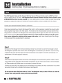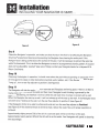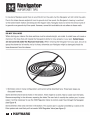
1
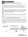
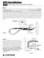
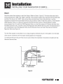
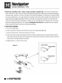
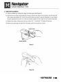
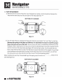
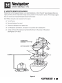
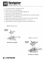
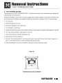
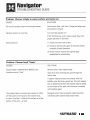
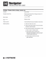
HAY WARD
Navigator
Installation Manual
СЭ HAYWARD'
Plunge into a sparkling clean pool... automatically.™
Navigator
INSTALLATION MANUAL
Congratulations on your purchase of the Navigator automatic pool cleaning system from
Hayward. The Navigator is the smart, efficient way to clean your in-ground pool. The Navigator
is powered by your pool's filter system and is designed to work well with most systems.
Therefore the performance of the Navigator in your pool will be relative to that power source.
Because the operation and performance of the Navigator are system reliant, there is a remote
possibility that a “service call” may be necessary to complete the proper installation of your
Navigator. Because this is an installation related call, it will be at the consumer s expense.
Also, one or more of the accessories designed for the Navigator, including additional hose
sections (if needed) might be applicable to your installation. Consult your Hayward Navigator
dealer for price and availability. For Technical Assistance, call Hayward at 1-800-227-1477
(USA only).
For Your Records
Record the following information for your convenience.
1) Purchase Date
2) Serial Number
The Navigator should not be used to clean the pool for spring start-up unless the conditions
noted in Step 1 are met. On those occasions, where your pool is subjected to an abnormal debris
load, maintenance steps should be taken to return the pool to “pre-installation” condition.
€) Installation
«2 [NSTALLING YOUR NAVIGATOR IS SIMPLE. ..
To prepare your pool for Navigator installation, please follow the easy steps listed below. These
instructions are also shown in the “Navigator Installation Video". After reading these instructions, the
“How To" installation video will walk you through the installation step-by-step, and it will also give you
some maintenance and trouble-shooting hints. These instructions apply to all Navigator models.
Step 1
Check the pool and remove any large objects that might interfere with the cleaner's operation. Check to
see that the water level is at the recommended level. Check the water chemistry. Make sure that the
water is properly balanced and that the pool is free from algae. Algae can adversely affect the
operation of the Navigator, and its performance.
Step 2
Clean or backwash the filter, and clean the hair and lint pot prior to installing the Navigator. Following the
installation of Navigator, clean the system at regular intervals according to individual pool conditions.
Step 3
There are nine (9) connector hoses and one (1) leader hose with a hose cuff. The hose cuff has a red sticker
attached to it that reads “REMOVE LABEL AND CONNECT TO CLEANER".
Connect the special Navigator hose sections together by pushing and twisting the tapered male connector
end of each hose firmly into the open female end of the adjacent hose section (see Figure 1). Depending on
the size and shape of your pool, all hose sections might not be used. However, the leader hose must be
used or the Navigator will not operate properly. It is not necessary to “Bottom Out” the connections, but
they must be tight enough to prevent any air leaks. Wetting the hose ends will make it easier to connect
the hose sections.
If Optional Leaf Canister is purchased, FIRST
install between 1st and 2nd hose sections. HOSE
SECTION
E >
то III TTD, | VUE
NAVIGATOR ^^, | и ces La
AAA ’ /
SECOND
ce SECTION
HAYWARD' |
) Installation
A) INSTALLING YOUR NAVIGATOR IS SIMPLE...
Step 4
The hose should reach from the skimmer or Hayward Vac Lock” to the furthest point in the pool, plus two
(2) extra hose sections. (The length of each hose section is four feet.) This extra length is absolutely
necessary for proper operation of the Navigator. |f the hose is not long enough, it will be necessary to
purchase additional hose sections from your Hayward Navigator dealer. The hose length supplied (40 feet)
has been determined to be sufficient for the majority of pools nationally. If your hose requirement is more
than this, you must obtain additional hose sections for your cleaner to work properly. After the correct hose
length has been assembled, fill hose completely with water. Insert Flow Gauge into the leader hose, then
attach the C-Clip of the gauge onto the first hose section. Make sure the Flow Gauge is under water. (see
Figure 2)
FLOW INDICATOR +. 7 ¿enema
IDESIRED POSITION) MIN
3 Fre
3 > Ta
» er V574
m > % FLOW GAUGE
TO SKIMMER
OR VAC-LOCK \
FIRST HOSE
SECTION A
= A
Figure 2 POOL DECK/COPING ~~"
E, A e pr
pr nd
Step 5
Turn the filter system on and allow it to run long
enough to eliminate any air in the system. Connect the
V093C Skimmer Cone to the tapered male end of the
vacuum hose if you are connecting the hose to your
skimmer. Then, insert the cone into the suction port of
the skimmer (see Figure 3) or, if you are using a
Hayward Vac Lock, insert the hose end directly
into the Vac Lock without using the cone. (Refer
to Important Tips for more specific skimmer A
information.)
ADAPTER
Figure 3
| HAYWARD
Installation
INSTALLING YOUR NAVIGATOR IS SIMPLE...
Step 6
Check the water flow reading on the Flow Gauge. (Refer to Step 4, Figure 2). The black disk should be in
the box between the "MIN" and "MAX" markings. If the setting is higher than required with the black disk
outside of the box on the "MAX" side and you have connected your hose to the skimmer, it will be
necessary to reduce the vacuum/water flow by using a valve or valves in the filter system, or the Hayward
V094 Regulator Valve or an optional Hayward Automatic Skimmer Vacuum Plate designed to adjust
vacuum/water flow. To install the V094 Regulator Valve, turn the filter system off. Remove the hose from
the VO93C Skimmer Cone, and after closing the Regulator Valve (Rotate the blue collar clockwise/toward +
until closed/tight], insert the Regulator Valve into the Skimmer Cone, and insert the hose end into the
Regulator Valve (see Figure 4).
Turn the filter system on and allow it to run long enough to eliminate any air in the system. Turn the blue
collar counter clockwise until the proper reading appears on the gauge.
If a Hayward Skimmer Vacuum Plate is to be used, follow the installation instructions included with the
Skimmer Vacuum Plate.
rT] REGULATOR
arsine VALVE
| vosac
— | CONE
ADAPTER
A
ra ]
TO TO MAIN DRAIN
PUMP (if applicable)
Figure 4
HAYWARD" |
€ Installation
«1 |NSTALLING YOUR NAVIGATOR IS SIMPLE...
The V094 Regulator Valve and the Hayward Skimmer Vacuum Plate can only be used to LOWER an initial
vacuum reading that is TOO HIGH. The Regulator Valve and the Skimmer Vacuum Plate cannot be used
to INCREASE the initial vacuum reading. An initial reading that is too low to meet the water flow setting
necessary to operate the cleaner is indicative of a system problem, and not a problem with the cleaner.
Contact your Hayward Navigator Dealer for assistance.
If vou have connected your hose to the Hayward Vac Lock, it will be necessary to adjust the vacuum/ water
flow using the 3-way valve at the filter system. The handle on the valve should be turned so that the Flow
(Gauge which is installed in the Navigator hose reads properly (refer to Figure 2). After the 3-way valve has
been properly adjusted, the vacuum gauge at the 3-way valve should be marked so that the water
flow can be adjusted by referring to the gauge at the valve, rather than reinstalling the Flow Gauge
in the hose each time an adjustment is necessary.
Step 7
Remove the Flow Gauge from the hose and keep it handy. You will want to use the Flow Gauge to check
the Navigator's operation from time to time if the Navigator is connected to your skimmer. If you are using
a Hayward Vac Lock, the Flow Gauge will only be necessary if you neglect to mark the valve gauge, or if
replacement of the valve gauge is necessary.
Step 8
Check the rear flap adjuster dial at the left rear of the Navigator. It should be set at position number || which
is the middle position (see Figure 5). Submerge the Navigator into the water and remove all of the entrapped
air. When escaping air bubbles cease, you are ready to connect the hose.
Connect the hose cuff of the leader hose to the Navigator and submerge the hose to remove all air as when
vacuuming the pool with a standard hand-vacuum (see Figure 6).
Do not use the return line/inlet water to “sink” the Navigator hose, as this will force air into the
cleaner head, and possibly cause performance problems.
| HAYWARD"
Installation
INSTALLING YOUR NAVIGATOR IS SIMPLE...
Figure 6
Figure 5
Step 9
Observe the Navigator in operation, and make sure that the return line flow is not affecting the Navigator's
SmartDrive® programmed steering and preventing the Navigator from-cleaning the entire pool. If the
Navigator hose is being pushed across the surface of the pool, it will be necessary to redirect the return line
water flow downward. This is to allow the Navigator to move in its programmed cleaning pattern. If your pool
does not have adjustable “eye ball” type return fittings, contact your Navigator dealer for a Hayward K19A
Return Line Diverter.
Step 10
Observing the Navigator in operation, it should move about the pool without spending an excessive amount
of time against the steps or other obstructions (vertical walls, ladders, etc). If the Navigator seems to get
“hung up”, turn the rear flap adjuster to position | (see Figure 5)
Step 11
The Navigator will climb the vertical walls in concrete and fiberglass swimming pools if there is at least a
twelve inch (12°) radius where the walls and floor meet. Navigator's wall climbing is governed by the
programmed steering, and therefore it will not climb the wall each time it comes in contact with a wall.
When the Navigator does start up a wall, it will not always go all the way up the wall. If the Navigator does
not seem to be “sticking” to the wall, turn the rear flap adjuster to position Ill (see Figure 5).
If the Navigator climbs to the water's surface and sucks air, turn the rear flap adjuster to Position |
(see Figure 5). If the cleaner continues to climb too high, reduce the water flow until proper operation is
achieved.
Approximately eighty percent (80%) of the dirt in a concrete pool will be on the floor of the pool.
Approximately twenty percent (20%) of the dirt will be on the walls. Your Navigator will spend its cleaning
time accordingly.
HAYWARD" |
25) Navigator
IMPORTANT TIPS
In one piece fiberglass pools there is very little dirt on the walls, but the Navigator will still climb the walls.
Due to the shape (severe angles) of most in-ground vinyl liner pools, the Navigator's cleaning is confined
to the bottom (both shallow and deep) and the hopper sides. Navigator does not climb the vertical walls of
in-ground or on-ground vinyl liner pools. However, normal dirt and debris do not adhere to these walls.
et ES
DO NOT COIL HOSE
When storing your cleaner the hose sections must be stored straight, not coiled. A coiled hose will create a
memory in the hose that will impede the Navigator's ability to move properly in your pool. Coiled hoses
are not covered under the Hayward warranty. When removing the Navigator from your pool, be sure to
grasp the cleaner by its handle, not by its hose, otherwise your Navigator might be damaged should the
hose disconnect from the cleaner.
“ ZN
1. Skimmers come in many configurations and cannot all be described here. Three basic types are
discussed however.
Some skimmers have two (2) holes in the bottom. There might be a valve, float or cover over the holes.
Remove everything in the skimmer, exposing the holes.The rear hole is usually the suction port. In some
cases it will be necessary to use the V094 Regulator Valve to control water flow through the Navigator
(see Figure 4)
Some skimmers have only one hole in the bottom. This suction port is usually controlled by a valve at the
filter system and most likely will not need a V094 Regulator Valve (see Figure 3).
В | HAYWARD
25) Navigator
IMPORTANT TIPS
Some skimmers have a vari-flow or diverter valve in the bottom of the skimmer. This valve can be turned to
regulate skimming and main drain suction. Turn the valve to full skim and then adjust the Flow Gauge
vacuum gauge by turning the valve toward main drain suction. Usually this valve is the same size as the
Navigator hose end, and it will therefore be necessary to purchase a V098 Hose Adapter (see Figure 7).
After the proper gauge reading has been established, the diverter valve will have to be locked in place with
a wedge of some kind so that it won't change position with operation of the Navigator.
2. Periodically check the vacuum/water flow to be sure that the Navigator is operating as efficiently as
possible. Remember, too much vacuum is just as bad as too little.
3. Periodically check to make sure that the Navigator hose is securely attached to its suction source
(i.e. Skimmer, Skimmer Vac Plate, Vac Lock, etc.)
4. Disconnect the Navigator hose from the skimmer/regulator valve, or, if using a “dedicated line”, turn
cleaner valve off prior to “backwashing”, so as not to restrict water flow.
5. Never coil the Navigator hose. Coiled hose is not covered under the warranty.
6. When the Navigator is out of the pool, always disconnect the leader hose from the Navigator head.
7. Always carry Navigator by the molded-in handle. Do not carry it by the hose.
8. When swimming in the pool, remove Navigator from the water.
9. If you are going to super chlorinate, shock, or add gas chlorine to your pool, make sure the cleaner and
its hose are removed prior to doing so.
Figure 7
| NAVIGATOR
+ HOSE
= /098 OPTIONAL
HOSE ADAPTER
= SKIMMER
DIVERTER
VALVE
TO MAIN DRAIN
HAYWARD" |
Fi
Navigator
MAINTENANCE TIPS
X
)
С
Я
1. Check the condition of the “shoes, wings and flaps” periodically. The shoes and wings have
wear indicators on their sides and should be checked occasionally to determine if they need replacing.
The shoe wear indicator is a line on the side of the shoe that appears as a difference in texture. When
this texture difference is no longer visible at the bottom of the shoe when viewed from either side, the
shoes must be changed (see Figure 8). Also on the side, the wing wear indicator is a horizontal line
which has three (3) vertical lines above it. When you can no longer see the horizontal line, the wings
must be changed (see Figure 9). The Hayward Navigator Tune-Up Kit is available from your dealer.
Shoes, wings and flaps may also be purchased separately.
2. SHOE REPLACEMENT:
a) Turn unit upside down.
b) Insert screwdriver between foot and shoe on one of the pods (see Figure 8).
¢) Using a lifting motion, remove the shoe from the foot.
d) Dip a new shoe in water and attach the shoe to the foot, making sure to put the small post into the
small hole and the large post into the large hole. These posts and holes are different sizes to prevent
the shoes from being improperly installed.
e) Repeat Steps b, c and d for each shoe.
WEAR MARK
WORN SHOE
E | HAYWARD'
™) Navigator
y
N74 MAINTENANCE TIPS
3. WING REPLACEMENT.
a) Using a screwdriver, remove the plugs from both pods (see Figure 9).
b) Remove the old wings by bending the wings up toward the sides of the cleaner, and lift them off
their hooks (see Figure 10). If any of the wing hooks are broken, take the Navigator to your dealer
for pod replacement as the unit will not function properly if the wings are not properly attached.
с) Replace the wings, making sure that you match the "L" (Left) and "R" (Right) of the pods.
d) Replace the pod plugs and tap them into place with the screwdriver handle.
WEAR MARK
Figure 9
Figure 10
HAYWARD | H
Navigator
MAINTENANCE TIPS
4. FLAP REPLACEMENT:
a) Remove the front and rear flaps from your Navigator by inserting a small screwdriver between the
flap and the lower body near the pivot point of the flaps (see Figure 11)
BOTTOM OF CLEANER
Figure 11
b) You will notice that your replacement flaps look similar but are marked “Front” and “Rear” on the flap.
Because the springs in the flaps are different, it is absolutely necessary to install the proper
flap in the front and rear of the unit. Failure to do so will result in unsatisfactory performance of the
Navigator. When installing the front flap, be sure that the extended leg of the spring is inserted into the
natch on the front of the lower body (see Figure 12). Push the flap in place. You will actually feel and
hear a snap when the flap is in place. Fold the flap in towards the bottom of the Navigator. You will feel
some resistance at this point (that is normal). As the flap snaps into its normal position, you will feel
the spring action and notice that the front flap is now in its normal operating position.
When installing the rear flap, the extended leg of the spring must fit against one of the flat surfaces of the
cam (see Figure 12).
BOTTOM OF CLEANER
Figure 12
| HAYWARD"
Navigator
MAINTENANCE TIPS
5. NAVIGATOR BUMPER REPLACEMENT:
Replacement of the Navigator Bumper is not recommended as a “Do It Yourself” repair, because there is a
slight possibility that the replacement might cause a problem in the propulsion system. We strongly suggest
that you consult your Hayward Navigator dealer for this repair.
A #2 Phillips screwdriver is necessary for this repair.
a) Turn off pump.
0) Remove Navigator from pool.
c} Disconnect Navigator from leader hose.
d) Turn Navigator upside down, and place it in a position that is steady/firm.
e) Locate and loosen the captive screw behind the throat in the center of the bottom
(see Figures 13, 14 & 15).
BUMPER
Figure 13
HAYWARD" |
Navigator
MAINTENANCE TIPS
f) Lift "Easy Opening Bottom” (see Figures 14 & 15)
g) Remove four (4) “A” screws (see Figure 13).
h) Lift the Lower Body Assembly off the Navigator (see Figure 13).
1) Remove four (4) “B" screws (see Figure 13).
j) Remove bumper carefully, making sure that other cleaner parts are not moved or disturbed.
k) Remove two (2) "C” screws (see Figure 13).
|| Replace bumper, again making sure that other cleaner parts are not moved or disturbed.
m) Reinstall screws and parts, following steps in reverse — k, ¡, h, g, f, e, d, c.
n) Reinstall Navigator in pool per installation instructions and/or installation video.
Figure 14 - Navigator Concrete
Figure 15 - Navigator Vinyl
CAPTIVE NN
BOTTOM OF CLEANER SCREW —
BOTTOM OF CLEANER
| HAYWARD"
Removal Instructions
“EASY OPENING BOTTOM"
“EASY OPENING BOTTOM".
The purpose of the "EASY OPENING BOTTOM" is to allow quick access to the turbine/vacuum chamber for
easy cleaning and maintenance.
Should the Navigator stop moving or become sluggish due to debris trapped in the throat or inside the unit,
the turbine/vacuum chamber is accessible following the instructions on pages 12 and 13 of this manual.
1.
OS QO =J Oo On B= LW ka
Turn off pump.
. Remove Navigator from pool.
. Disconnect Navigator from leader hose.
. Turn Navigator upside down.
. Locate and loosen the captive screw behind the throat in the center of the bottom (see Figures 14 and 15)
. Lift “Easy Opening Bottom” (see Figures 14 and 15)
. Clean turbine/vacuum chamber (see Figure 16).
. Check turbine for free movement.
. Reinstall "Easy Opening Bottom” by lining up the cover screen with the two slots shown in Figures 14
and 15. Then slide the cover in place and tighten the captive screw.
10. Reinstall Navigator in pool per installation instructions and/or installation video.
Figure 16
TURBINE/VACUUM CHAMBER
HAYWARD" |
Navigator
TROUBLESHOOTING GUIDE
Problem: Slow/no forward movement
CAUSES
Lack of/improper water flow through cleaner
Partial blockage of Navigator throat
Worn shoes
Worn wings
Improper cleaner model for application
SOLUTIONS
Check water flow with Flow Gauge and adjust as
per Step 6, Figure 2.
Clear blockage
Replace shoes
Replace wings
Call 1-800-227-1477 (U.S.A. only)
Problem: Cleaner fails to climb vertical walls gunite/concrete pool
CAUSES
Improper shoes for application
Lack of/improper water flow through cleaner
Partial blockage of Navigator throat
Worn shoes
Worn wings
Hose too short
Improper tension on rear flap
| HAYWARD"
SOLUTIONS
Call 1-800-227-1477 (U.S.A. only)
Check water flow with Flow Gauge and adjust as
per Step 6, Figure 2.
Clear blockage
Heplace shoes
Heplace wings
Install additional hose sections per installation
instructions
Turn rear flap adjuster to |||
Navigator
(E)
a НН ®
TROUBLESHOOTING GUIDE
Problem: Cleaner climbs to water surface and sucks air
CAUSES
Too much/improper water flow through cleaner
Improper tension on rear flap
Steering failure
SOLUTIONS
Check water flow with Flow Gauge and adjust per
instructions in Step 6.
Turn rear flap adjuster to |
If still climbing too much, reduce water flow until
proper operation is achieved
1) Check and clean rear screen
2) Check to see that cone gear is free and rotates
smoothly in both directions
3) Check medium turbine and spindle gear
assemblies for malfunction
Problem: Cleaner head “floats”
CAUSES
Cleaner head is HEAVIER than WATER, and
therefore cannot “float”
The cleaner head is actually being pulled or lifted
off the bottom of the pool by the cleaner hose,
or return line flow — either at the surface or at the
bottom of the pool — or bath
SOLUTIONS
Remove all air from cleaner head
Stop all air from entering the pool through the
return lines
If cleaner head and hose are covered with fine
bubbles, give the hose a good tug. This will release
the air bubbles and allow the cleaner head to settle
to the bottom of the pool until the hose is covered
with bubbles again
Readjust return lines to prevent water flow from
interfering with cleaner head and/or hose
HAYWARD" |
Navigator
TROUBLESHOOTING GUIDE
Problem: Cleaner sticks at steps, corners, etc.
CAUSES SOLUTIONS
Improper water flow Check water flow with Flow Gauge and adjust as
per Step 6, Figure 2.
Worn shoes Replace shoes
Worn wings Replace wings
Hose too short Install additional hose per installation instructions
Steering failure 1) Check and clean rear screen
2) Check to see that cone gear is free and rotates
smoothly in both directions
3) Check steering program and troubleshoot - then:
a) clean, repair or replace gearbox
b) check pod/A-frame connection and
REPLACE IF NECESSARY. DO NOT ATTEMPT
TO RETIGHTEN LOOSE PODS.
c) check medium turbine and spindle
gear assemblies
| HAYWARD"
=) Navigator
@ DISCLAIMER
A) Pool plaster is affected by age, water chemistry, etc.
B) Pool plaster can deteriorate over a period of time.
C) The integrity of “good” pool plaster is such that a pool vacuum cleaner - automatic or manual cannot
remove that plaster.
D) The integrity of “good” pool plaster is such that the plaster will cause wear on the Navigator -
not vice versa.
E) Vinyl is affected by age, sunlight and water chemistry.
F) Vinyl can become brittle and weak.
G) Vinyl can also be affected by the installation and the pools surroundings.
H) When installing the Navigator, you must assume all responsibility for the condition of the pool and the
pool's surroundings.
To better serve you, please have the following information available if you call Hayward's
Technical Service Department at 1-800-227-1477 (U.S.A. only):
1) The Purchase Date of your Navigator.
2) The Serial Number of your Navigator.
3) The number of Hose Sections used.
4) A current water flow indicator setting (refer to Step 6, Figure 2).
HAYWARD' |
HAYWARD POOL PRODUCTS, INC.
2875 Pomona Boulevard, Pomona, CA 91768
909-594-1600 Toll Free: 800-227-1477
www.haywardnet.com
Copyright © Hayward Pool Products. All rights reserved. Manufactured, sold and distributed by
Hayward Pool Products, Inc. Smartdrive® is a registered trademark of Hayward Products.