1
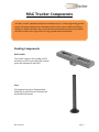
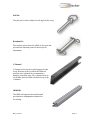
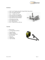
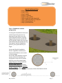
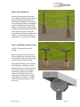
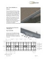
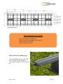
Installation Manual May 14, 2012 Contents MAG TRACKER Components............................................................................................1 Mount Installation……........................................................................................................7 Module Installation & Grounding…………….............................................................11 Maintenance…………………………….…….………………………………………………….14 Warranty…………………………………….………………………………………………..…...14 Contact Information...................................................................................................…...14 May 14, 2012 MAG Tracker Components The MAG Tracker (Manually Adjusted Groundmount) is a visually appealing ground mount PV system engineered to maximize annual solar revenue while providing a lifetime of simple operation. Easy to install and customizable to almost any module, the MAG tracker is the right choice for any ground mount installation. Racking Components MAG Cradle The Cradle supports the racking and PV modules, as well as providing the rotation point and adjustment pin holes. Post The Engineered post is designed with flexibility in mind. Slots are included for horizontal adjustment. May 14, 2012 Page 1 Pull Pin The pull pin is used to adjust the tilt angle of the array. Rotation Pin The rotation pin securse the saddle to the post and provides the rotation point for the arrays tilt adjustment C-Channel C-Channel is the north to south support for the array. Notches in the top allow the IWM rail position to be adjusted to accommodate a number of module sizes. The c-channel bolts to the Saddle, then the IWM is bolted on top of the c-channel IWM RAIL The IWM rail supports the modules and provides wire management channel for the wiring. May 14, 2012 Page 2 T-Bar Joiner The T-Bar is used to join the IWM rail to the CChannel. T-Bar Splice The Joiner is used to join lengths of IWM rail end to end. End Clamp The End Clamp is used to secure the panels to the IWM rail Stand Off The standoff block is used under the End clamps. There are 2 standoff block heights depending on the module thickness Mid Clamp The Mid Clamp is used to secure the panels to the IWM rail May 14, 2012 Page 3 Foundation Components Sonotube Sono tube size depends on the foundation required. See foundation drawings for details. Anchor Bolts 4x 1”x 48” long anchors per foundation. For anchoring the post to the foundation Anchor Plate The 4 anchors are secured to the plate which gets embedded in the concert. Anchor Bolt Template Used to align anchors to ensure proper spacing. May 14, 2012 Page 4 Hardware 5/16”, 2-1/2” Stainless Steel Bolt (Length Module dependent) 5/16, 3/4” Stainless Steel Bolt 3/8” , 1” Stainless Steel Bolt 3/8” , 1” Stainless Carriage Bolt 3/8” Stainless Steel Lock Washers 5/16” Stainless Steel Lock Washer 3/8" Stainless Steel Flat Washers 3/8” Stainless Steel Nut 5/16” Stainless Steel Nut 3/4, 1” Wood Screws #10, 1” Stainless Steel Teck Screw Tool List Mason String 1/2” Deep Socket 3/8 drive Torque Wrench. Ratchet 3/8 drive 1/2 Open End Wrench Measuring tape Chalk Line Cordless Drill 17/64” Drill Bit May 14, 2012 Page 5 Example Layout May 14, 2012 Page 6 MOUNT INSTALLATION • Step 1: Foundations • Step 2: Posts • Step 3: Saddle • Step 4: C-Channel • Step 5: T-Bar to IWM • Step 6: Stand offs and clamp bolts • Step 7: IWM Assembly to C-Channel • Step 8: Repeat Steps 5 - 8 • Step 9: Join IWM Rails Step 1: Foundation and Site preparation Creating the foundations is the most critical step in the process. It is important to get them correctly located and the anchors properly aligned otherwise the system will not fit together. Make sure you read and understand this manual, the big foot manual, and the foundation plan for your system before you begin. Locate and dig the foundation. Ensure alignment and distances between foundations are accurate to the drawings. Use anchor bolt template to insure proper anchor bolt spacing. Use string line or laser level to insure bolts are correctly oriented and aligned between each foundation. Anchor bolts must align north/south with in 1”. Anchor bolts rotational alignment must be within 2 degree. This is critical to insure that the system will assemble properly and not bind when rotated. May 14, 2012 Page 7 Step 2: Post Installation Mount post on anchor bolts using slots and string line to insure post are aligned. Improper alignment will result in the racking not contacting the C-Channel properly or binding on rotation. Height can be adjusted by using a 1” hex nut and washer under the base plate. Horizontal adjustment can be done using the slots in the base plate. Once posts are aligned use washer, 1”lock washer and hex nut and washer to secure the post down. Step 3: Install MAG Cradle on Post *NOTE: This requires at least 2 people. Notice orientation of Cradle before lifting. Adjustment holes must be on the south side of post. Have both the rotation pin and Pull Pin ready. Lift Cradle with one person on each end. Align the rotation hole on the saddle and the post. Insert Rotation Pin. Rotate Cradle to the 0 degree maintenance position and insert rotation pin. Using laser level or string across the top of the saddle, verify that all 4 Cradle are straight and level before moving on to the next step. May 14, 2012 Page 8 Step 4: Attach C-Channel Locate the predrilled holes on the sides of the C-Channel and the side of the Cradle to bolt them together. Attach C-Channel to Cradle using 3/8” bolts, lock washers, and hex nut. Step 5:T-bar to IWM Slide the 5/16 bolts for the T-Bar down the slot in the side of the IWM rail. Measuring from one end, space the bolts along the IWM rail so that they are in the correct location to join to the C-Channel. When measuring, note the orientation of the IWM is open side towards the south. Place the T-bar on the bolts and add the lock washer and hex nut. Tighten finger tight in case you have to slide the T-bar when aligning with the C-Channel. Step 6: Attach Bolts and Standoffs Slide the 5/16 x 2 -1/2” hex bolts for the Pi Clamps down the channel measuring to where they will be located for panel clamping. Refer to your panel manufactures instructions for proper clamping locations. If the rail has end clamps you can place the stands offs and tighten them down in the proper clamping location for your panel. If a joiner is used ensure the 5/16” x 1” bolts are located in the slot as this will be difficult to do later. May 14, 2012 Page 9 Step 7: Place IWM Rail on CChannel Place the rail so the T-Bar is sitting on the C-Channel over the slot with the opening side of the IWM facing south. Put the 3/8” Carriage bolt up through the C-Channel and T-Bar. Finger tighten the 3/8” lock washer and nut to the carriage bolt in case you need to shift the rail in the slot. Measure from the end of the CChannel to the rail and slide the rail along the slot to proper location according to the module manufactures installation instructions. Step 8: Repeat step 5 and 6 for remaining rail Step 9: Join IWM Join the ends of the IWM rail using the joiner plate and 5/16” x 1” Hex Bolts placed along the slot in step 6. Use a 5/16” lock washer and hex nut to secure. May 14, 2012 Page 10 . Module Installation & Grounding • Step 10: Attach Grounding Lugs • Step 11: Attach Grounding Lug to Modules • Step 12: Place 1st module • Step 13: Repeat step 12 Step 10: Attach Grounding Lugs Attach grounding lugs to every IWM rail, c-channel, cradle, and post. Torque ground lugs to 10 ft-lb (13.5 Nm) May 14, 2012 Page 11 Step 11: Attach Grounding Lug to Modules Attach grounding lugs to each module using bolt and nut supplied with the lugs. Torque ground lugs to 10 ft-lb (13.5 N-m) Step 12: Place 1st module Place first module secure with pi clamp in location according to module manufacturers installation manual. On the outside clamps you can torque stand off and pi clamp nuts to 11 ft-lbs (14.9 N-m). But leave the inside ones loose to lay the next module under. Complete any necessary electrical work, including grounding with copper wire through the lugs attached in the previous steps. May 14, 2012 Page 12 Step 13: Repeat step 12: Repeat step 12 for remaining modules. May 14, 2012 Page 13 Preventive Maintenance Step 1: Rust Regular inspection should be done for rust. If rust if found it should be cleaned of with wire brush and the area sprayed with galvanize pant. Step 2: Fasteners Fasteners should also be inspected regularly or immediately after high winds to make sure they are not loose. If any are suspect they should be re-tightened to the proper torque specification. Warranty MAG Tracker (the “Product”) will be free from defects in materials and workmanship as described below under normal installation, application, use and service conditions, for a period of ten years from date of original purchase. This warranty does not cover cosmetic damage including rust, damage from accident, negligence, misuse, acts of God, or any Product installed to SunRise Power Corp. Canada’s specifications by an authorized installer. For more information please see MAG Tracker limited Warranty document or contact Sunrise power. May 14, 2012 Page 14