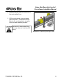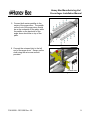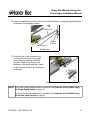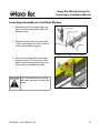
1
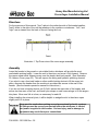
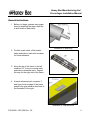
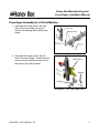
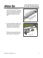
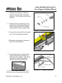
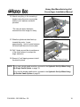
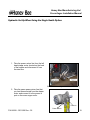
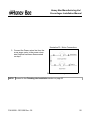
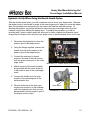
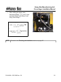
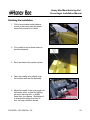
Pre-2008 Production
Header and Swather
Cross-Auger
Installation Manual
Honey Bee Manufacturing Ltd.
Cross Auger Installation Manual
Contents.
Before You Begin.....................................................................................3
General Instructions................................................................................5
Cross Auger Assembly for a 25 Foot Machine........................................7
Cross Auger Assembly for a 30-45 foot Machine..................................12
Hydraulic Set Up When Using the Single Swath Option.......................19
Hydraulic Set Up When Using the Double Swath Option......................21
Finishing the Installation........................................................................23
P/N 94199 - 03/31/09 Rev - 02
1
Honey Bee Manufacturing Ltd.
Cross Auger Installation Manual
P/N 94199 - 03/31/09 Rev - 02
2
Honey Bee Manufacturing Ltd.
Cross Auger Installation Manual
Before You Begin
Unpack the unit, and check the parts supplied against the packing list enclosed. Familiarize
yourself with the components, their locations once installed, and the sequence of assembly by
referring to the contents of this manual. Pay special attention to the orientations of the
bearings.
Smooth the shafts, and universal sleeves with emery cloth if needed, and test the fit of all
bearings and universals before you attempt to install them. Use a good anti-seize compound
on all connections involving the auger shafts. This will aid assembly, and will make
disassembly much easier if repairs are required at a later date.
Protect the drapers with a sturdy surface, such as sheets of plywood to prevent
damage to the drapers while positioning and lifting the auger sections.
Kit Contents
DESCRIPTION
BOLT 3/8 X 3/4 UNC
BOLT 3/8 X 1
UNC
BOLT 3/8 X 1-1/2 UNC
BOLT 1/2 X 1-3/4 UNC
BOLT 1/2 X 4
UNC
BOLT 3/4 X 4-1/2 UNC
BOLT 3/8 X 1 NC CARR GR5
TEK SCREW 1/4 X 3/4
NUT 3/4 UNC NYLOCK
WASHER FLAT 3/8
WASHER FLAT 1/2
WASHER SAE 3/8
WASHER SAE 1/2
WASHER LOCK 3/8
NUT 1/2 UNC C/LOCK
NUT 3/8 UNC C/LOCK
BOLT 3/8 X 3 NC CARR GR5
SAFETY WALK ADHSV- 2"
BRG L/D FLNG PP206
FLANGETTE 3 BOLT
BOLT 1/2 X 1-1/4 NC CARR GR5
KEY 1/4 X 1/4 X1-1/4 DAN
NUT RODCPLG 3/8 UNC
SET SCREW SQ.HD 1/2 X 1.5
BRG SPHRCL-3 SEAL-NO SETS
P/N 94199 - 03/31/09 Rev - 02
QTY.
4
10
6
2
2
2
3
3
2
14
4
4
5
4
9
24
8
4
2
2
5
5
4
2
3
DESCRIPTION
U-JNT 1" YOKE
WASHER 3/8 SEAL BONDED
SHIELD-CNTR XAUG PLST
UHMW-PDL-CNTR XAUG GBP
JACK-XAUG ASSY 07
SPCR 1.660 X 1.278 X 0.5
CLAMP PLT-JACK-XAUG
XAUG WD-240" CNTR
BRG MNT-XAUG FRMD
BRKT-L-XAUG FRMD
CLAMP PLT-XAUG
LOCK WD-SLV JACK-XAUG
SHIELD WD-HSG XAUG/BRG GBP
MTR MNT WD-XAUG
NUT 1/2 UNC
WASHER LOCK 1/2 PLTD
NEEDLE VALVE #10
ELBOW
10MB-10MJ -90
HYDRAULIC MOTOR-WHITE 115cc
HH08 22 10FJX-10FJX
U-BOLT 1/2 X 11.25 X 6.25
XAUG/JACK MNT WD-RETRO
SHIM-XAUG-RETRO
QTY.
3
4
1
2
2
2
2
1
1
2
2
2
2
1
2
4
1
2
1
1
2
2
2
3
Honey Bee Manufacturing Ltd.
Cross Auger Installation Manual
Directions
For the purposes of this manual, "front" refers to the cutter-bar side of the header/swather,
"back" refers to the side of the unit that attaches to the combine or windrower. "Left," and
"right" are as viewed from the back of the unit facing the front.
Illustration 1: Top-Down view of the cross auger assembly.
Assembly
Lower the header to the ground or onto stable blocks, whichever will provide the most
comfortable working height. Lower the reel to the stops, and move it fully forward. Remove
the narrow sheet metal valance covers over the draper deck back panels. (See Illustration
39: Valance Cover, page 23.) This will expose the wiring and hydraulic plumbing channel.
If you elect to use a front-end loader or other mobile hoisting device to lift the auger into
place, dismount the header from the combine to provide clear access to the rear of the
header. (See the header operator's manual for instructions.)
If you do not have a hoisting device, set (2) 2x4's across the main tube of the header, and
across two tine arms of the reel, and have nylon straps or small come-alongs to lift the augers
into place. Move one 2x4 at a time, as necessary for each lift.
When installing the universal joints, it will be helpful to wedge the slot in the sleeve open
slightly until it is in place.
Care must be used when working around pressurized hydraulic systems.
All fittings must be securely connected before the windrower is started,
and power is applied to the swather. Serious injury, and/or damage to
equipment may result from poor connections.
P/N 94199 - 03/31/09 Rev - 02
4
Honey Bee Manufacturing Ltd.
Cross Auger Installation Manual
General Instructions.
1. Before you begin, prepare each auger
drum by attaching the auger shaft key
to both shafts of each drum.
Illustration 2: Shaft Key
2. Find the exact center of the header
frame and make a mark with a marker
for future reference.
3. Along the top of the frame to the left,
measure 121" from your center mark
and make a reference mark. Repeat
this step for the right side of the frame.
Illustration 3: Reference Marks
4. At each reference mark, measure 1"
back from the front edge of the frame
and affix the grip adhesive as shown in
the illustration to the right.
Illustration 4: Grip Adhesive
P/N 94199 - 03/31/09 Rev - 02
5
Honey Bee Manufacturing Ltd.
Cross Auger Installation Manual
5. Loosely attach the mounting plates to
the main frame of the header using the
u-bolts, nuts and washers supplied.
Do not tighten until you have
connected and aligned the auger
drums.
Illustration 5: Mounting Plate Installation
NOTE: If you own a 25 foot machine, proceed to the Cross Auger Assembly for a 25 Foot
Machine section on page 7.
If you own a 30 – 45 foot machine, proceed to the Cross Auger Assembly for a 3045 Foot Machine section on page 12.
P/N 94199 - 03/31/09 Rev - 02
6
Honey Bee Manufacturing Ltd.
Cross Auger Installation Manual
Cross Auger Assembly for a 25 Foot Machine.
1. Assemble the auger jack for the right
side of the cross auger, be sure to
enclose the bearing within the bearing
clamp.
Illustration 6: Right Side Auger Jack
2. Assemble the auger jack for the left
side of the cross auger. Ensure that the
motor mount is properly secured to the
rear side of the jack as shown.
Motor Mount
Spacers
Bearing
Illustration 7: Left Side Auger Jack
P/N 94199 - 03/31/09 Rev - 02
7
Honey Bee Manufacturing Ltd.
Cross Auger Installation Manual
3. Slide both auger jacks onto each end of
the center auger drum.
4. Lift the center auger drum and auger
jacks into place. Connect both of the
jacks to the mounting plates using the
nuts, bolts and washers provided.
Care must be taken when lifting
the auger drum as it can be quite
heavy.
Illustration 8: Mounting the Auger Drum
P/N 94199 - 03/31/09 Rev - 02
8
Honey Bee Manufacturing Ltd.
Cross Auger Installation Manual
5. Connect both center paddles to the
center of the auger drum. The paddle
on the front of the auger drum should
be on the underside of the plate, while
the paddle on the back side of the
auger drum should be on top of the
plate.
Illustration 9: Center Paddle Assembly
6. Connect the universal joint to the left
end of the auger drum. Secure on the
shaft using the set screw and bolt
provided.
Universal Joint
Illustration 10: Attaching the U-Joint
P/N 94199 - 03/31/09 Rev - 02
9
Honey Bee Manufacturing Ltd.
Cross Auger Installation Manual
7. Assemble the motor and it's fittings.
a. Connect the needle valve to the
bottom of the motor.
b. Screw the 2 elbows into the back of
the manifold valve.
Motor
Elbows
Needle Valve
Illustration 11: Motor Assembly
8. Connect the motor assembly to the
universal joint and the motor mount
using the nuts and bolts provided.
9. Secure the universal joint using the set
screw and bolt provided.
Illustration 12: Connecting Motor Assembly
P/N 94199 - 03/31/09 Rev - 02
10
Honey Bee Manufacturing Ltd.
Cross Auger Installation Manual
10. Attach the stability arm to the motor mount and the deflector using the supplied fittings,
as shown in the illustration below.
Stability Arm
Deflector
Bracket
Rubber Mounts
Illustration 13: Connecting the
Stability Arm
11. Connect both of the Universal Joint
Covers over each end of the auger
drum using the washers and bolts
provided. Make sure that you use
washers on the inside and the outside
of the cover as shown in the illustration
to the right.
Illustration 14: Attaching the U-Joint Covers
NOTE: If you own a single swath machine, proceed to the Hydraulic Set Up When Using
the Single Swath Option on page 19.
If you use the double swath option, proceed to the Hydraulic Set Up When Using
the Double Swath Option on page 21.
P/N 94199 - 03/31/09 Rev - 02
11
Honey Bee Manufacturing Ltd.
Cross Auger Installation Manual
Cross Auger Assembly for a 30-45 foot Machine.
1. Assemble both of the auger jacks, be
sure to enclose the bearing within the
bearing clamp.
2. Slide both auger jacks onto each end
of the center auger drum (#2 in the top
down view located on page 4).
Illustration 15: Auger Jack Assembly
3. Lift the center auger drum and auger
jacks into place. Connect both of the
jacks to the mounting plates using the
nuts, bolts and washers provided.
Care must be taken when lifting
the auger drum as it can be quite
heavy.
Illustration 16: Auger Jack Installation
P/N 94199 - 03/31/09 Rev - 02
12
Honey Bee Manufacturing Ltd.
Cross Auger Installation Manual
4. Connect both center paddles to the
center of the auger drum. The paddle
on the front of the auger drum should
be on the underside of the plate, while
the paddle on the back side of the
auger drum should be on top of the
plate.
Illustration 17: Center Paddle Assembly
5. On the auger extension closest to the
right side of the header (marked as #1
on the top down view), connect a
universal joint to the shaft pointing
towards the center of the machine.
6. Tighten the set screw and bolt on the
portion of the universal joint that you
just connected to the auger shaft.
Illustration 18: U-Joint Assembly
P/N 94199 - 03/31/09 Rev - 02
13
Honey Bee Manufacturing Ltd.
Cross Auger Installation Manual
7. Assemble the bearing and bearing
mount for the right side of the auger
extension. Do not tighten the nuts and
bolts yet.
8. Slide the bearing and bearing mount
assembly on to the shaft of the auger
drum on the right side of the header
(marked as #1 on the top down view).
Illustration 19: Bearing Mount Assembly
9. Connect the other side of the universal
joint to the center auger extension.
10. Tighten the remaining set screw and
bolt on the universal joint.
Illustration 20: U-Joint
11. Connect both of the L brackets to the
reel arm and the reel arm brace at
both ends of the header. Leave all the
connections loose until the auger
extensions have been attached.
All Grain Belt Plus models connect the L-bracket to
the reel arm via a nut, washer and bolt (see above)
P/N 94199 - 03/31/09 Rev - 02
Illustration 21: L Bracket Installation
14
Honey Bee Manufacturing Ltd.
Cross Auger Installation Manual
12. Attach the bearing mount that you had
connected to the auger shaft in step 7
to the L bracket on the right side of the
header. Leave the bolts loose.
-The reel arm brace has been
removed from this image for clarity.
Illustration 22: Bearing Mount Connection
13. Attach the universal joint cover over
top of the universal joint that you had
previously connected. Make sure that
you use washers both behind and in
front of the cover.
14. You can now tighten up the L bracket
and bearing assembly on the right
hand side of the header after making
sure everything is lined up.
U-Joint Cover
Illustration 23: U-Joint Cover
15. For the remaining auger extension
(marked as #3 on the top down view),
attach the second universal joint to the
shaft pointing towards the center of the
header.
16. Tighten the bolt and set screw for the
portion of the universal joint that you
connected to the shaft.
Illustration 24: U-Joint
P/N 94199 - 03/31/09 Rev - 02
15
Honey Bee Manufacturing Ltd.
Cross Auger Installation Manual
17. Assemble the motor and it's fittings.
a. Connect the needle valve to the
bottom of the motor.
b. Screw the 2 nipples into the side of
the motor.
c. Connect the motor to the motor
mount using the nuts and bolts
provided.
Motor Mount
Motor
Elbows
Needle Valve
Illustration 25: Motor Assembly
18. Connect the remaining end of the
second universal joint to the remaining
shaft of the center auger drum.
19. Tighten the last bolt and set screw for
the universal joint.
20. Attach the universal joint cover to the
spacers, using the bolts and washers
provided.
P/N 94199 - 03/31/09 Rev - 02
U-Joint Cover
Illustration 26: U-Joint Cover
16
Honey Bee Manufacturing Ltd.
Cross Auger Installation Manual
21. Connect the final universal joint to the
shaft of the last auger extension (#3 on
the top down view).
22. Tighten the bolt and set screw on the
universal joint.
Illustration 27: Final U-Joint Installation
23. Slide the shield as far as you can over
the end of the auger extension. Do
not screw into place yet.
Illustration 28: Initial Shield installation
24. Connect the the motor assembly to the
universal joint which you had just
attached to the end of the final auger
extension (#3 in the top down view)
25. Tighten the last bolt and set screw on
the universal joint.
Illustration 29: Motor Assembly Connection
P/N 94199 - 03/31/09 Rev - 02
17
Honey Bee Manufacturing Ltd.
Cross Auger Installation Manual
26. Attach everything to the remaining L
bracket using the motor mount plate
and the nuts, washers and bolts
provided.
Connect Here
-The reel arm brace has been
removed from this image for clarity.
Illustration 30: L Bracket Connections.
27. Slide the cylindrical shield back up
towards the motor. Leave
approximately 1 inch of space between
the shield and the motor mount plate.
28. Drill 3 holes around the circumference
of the shield where it overlaps the
auger extension.
1”
29. Screw in 3 self tapping screws to hold
the shield in place.
Self Tapping Screws
Illustration 31:Final Shield Installation
NOTE: If you own a single swath machine, proceed to the Hydraulic Set Up When Using
the Single Swath Option on page 19.
If you use the double swath option, proceed to the Hydraulic Set Up When Using
the Double Swath Option on page 21.
P/N 94199 - 03/31/09 Rev - 02
18
Honey Bee Manufacturing Ltd.
Cross Auger Installation Manual
Hydraulic Set Up When Using the Single Swath Option.
1. Take the power return line from the left
hand draper motor located on the back
of the header and disconnect it from
the steel line.
Illustration 32: Draper Motor Connections
2. Take the same power return line that
you had disconnected from the draper
motor and connect it to the power in
port on the cross auger motor.
Power In
P/N 94199 - 03/31/09 Rev - 02
Power Return
19
Honey Bee Manufacturing Ltd.
Cross Auger Installation Manual
Illustration 33: Motor Connections
3. Connect the Power return line from the
cross auger motor to the power return
steel line that had been disconnected
on step 1.
Illustration 34: Basic Hydraulic Schematic
NOTE: Proceed to the Finishing the Installation section on page 23
P/N 94199 - 03/31/09 Rev - 02
20
Honey Bee Manufacturing Ltd.
Cross Auger Installation Manual
Hydraulic Set Up When Using the Double Swath Option.
With the double swath option, you will sometimes need to move your draper deck. Because
the draper motor is connected in series to the cross auger motor, when you move the draper
deck, the hydraulic lines connecting the two motors will interfere with the process. To
alleviate the problem, you will be required to disconnect the cross auger motor from the
hydraulic circuit when shifting the draper deck. To simplify the procedure, you will be
provided with 2 quick couplers which will allow you to easily complete the hydraulic circuit
using either the draper motor and the cross auger motor or just the draper motor on it's own.
1. Disconnect the hydraulic line from the
power in port of the draper motor.
2. Using the fittings supplied, connect the
female end of a quick coupler to the
power in port of the draper motor.
3. Connect the male end of a quick
coupler to the end of the line coming
from the power return port of the cross
auger motor.
Illustration 35: Draper Motor Quick Coupler
4. Attach one end of the extra hydraulic
line provided with the cross auger kit,
to the power in port of the cross auger
motor.
5. Connect the female end of a quick
coupler to the remaining end of the
extra hydraulic line.
Power In
6. Take the male end of the final quick
coupler and connect it to the available
end of the hydraulic line that you had
disconnected from the power in port of
the draper motor in step 1.
P/N 94199 - 03/31/09 Rev - 02
Power Return
Illustration 36: Motor Connections
21
Honey Bee Manufacturing Ltd.
Cross Auger Installation Manual
7. When shifting the draper deck,
disconnect fittings 1, 2, 3, and 4, then
reconnect fitting 1 with fitting 4, and
fitting 3 with fitting 2.
Illustration 38: Quick Coupler Assembly
Illustration 37: Double Swath Schematic
NOTE: Proceed to the Finishing the Installation section on page 23
P/N 94199 - 03/31/09 Rev - 02
22
Honey Bee Manufacturing Ltd.
Cross Auger Installation Manual
Finishing the Installation.
1. Fit the narrow sheet metal valance
covers in place and mark the points
where they contact the U-bolts.
Illustration 39: Valance Cover
2. Cut out half-circles at these marks to
provide clearance.
3. Re-fit and secure the panels in place.
Illustration 40: Valance Cover Cut-Out
4. Open the needle valve slightly, start
the combine and test the assembly.
5. Adjust the speed of the cross auger via
the needle valve, so that the flighting
will move the crop with, or slightly
faster than, the drapers. Be prepared
to change this setting from time to
time, as crop conditions dictate.
P/N 94199 - 03/31/09 Rev - 02
Illustration 41: Needle Valve Location
23