1
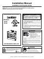
Installation Manual
Installation and Fireplace Setup
INSTALLER: Leave this manual with party responsible for use and operation.
OWNER: Retain this manual for future reference.
NOTICE: DO NOT discard this manual!
Model(s):
EL36
EL42
WARNING: If the information in these
instructions is not followed exactly, a fire
or explosion may result causing property
damage, personal injury, or death.
• DO NOT store or use gasoline or other flammable vapors and liquids in the vicinity of this
or any other appliance.
• DO NOT overfire. Overfiring will void your
warranty.
• Comply with all minimum clearances to combustibles as specified. Failure to comply may
cause house fire.
WARNING
HOT SURFACES!
Glass and other surfaces are hot during
operation AND cool down.
Hot glass will cause burns.
• DO NOT touch glass until it is cooled
• NEVER allow children to touch glass
• Keep children away
• CAREFULLY SUPERVISE children in same room as
fireplace.
• Alert children and adults to hazards of high temperatures.
WOODBURNING FIREPLACE
Installation and service of this fireplace should be
performed by qualified personnel. Hearth & Home
Technologies recommends NFI certified professionals, or technicians supervised by an
NFI certified professional.
High temperatures may ignite clothing or other flammable
materials.
• Keep clothing, furniture, draperies and other flammable
materials away.
WARNING
Fire Risk.
For use with solid wood fuel only.
Other fuels may overfire and generate
poisonous gases (i.e. carbon monoxide).
Heatilator • EL36/EL42 • 4044-188 Installation Manual • Rev G • 01/28/15
1
Safety Alert Key:
DANGER! Indicates a hazardous situation which, if not avoided will result in death or serious injury.
WARNING! Indicates a hazardous situation which, if not avoided could result in death or serious injury.
CAUTION! Indicates a hazardous situation which, if not avoided, could result in minor or moderate injury.
NOTICE: Indicates practices which may cause damage to the fireplace or to property.
•
•
•
•
Table of Contents
1 Product Specific & Important Safety Information
A. Fireplace Certification
B. Non-Combustible Materials
C.Combustible Materials
2 Getting Started
A. Typical Fireplace System
B. Design and Installation Considerations
1. Selecting Fireplace Locations
2. Locating Fireplace & Chimney
C.Tools and Supplies Needed
D.Inspect Fireplace and Components
E. Fireplace System Requirements
3 Framing and Clearances
A. Fireplace Dimensions
B. Clearances
Minimum Clearances to Combustibles
C.Construct the Chase
D.Frame the Fireplace
E. Secure and Level the Fireplace
F. Protective Metal Hearth Strips
G.Outside Air Kit (optional)
4 Chimney and Termination Requirements
A. Chimney Requirements
B. Offsets/Returns
C.Termination Requirements
5 Chimney Installation
A. Typical Chimney System
B. Assemble Chimney Sections C.Install Chimney Air Kit
D.Secure Offset/Return
E. Install Ceiling Firestops
F. Install Attic Insulation Shield
G.Roof Penetration
H.Install Chase/Chase Top
I. Termination Cap Requirements
J. Install Termination Cap
2
4
4
4
5
6
6
7
8
8
8
9
10
10
11
12
12
13
14
15
16
17
6Shrouds
A. Radiation Shield
B. Field Constructed Shrouds
1. Open Top Shroud 2. Mailbox Style Shroud 3. Roofed Style Shroud
7Finishing
A. Finishing Material
B. Hearth Extension, Building and Finishing
1. Hearth Extension 4” or more below
Fireplace Opening
2. Raised Hearth Extension Less Than 4” Below
Fireplace Opening
3. Fireplace Opening and Hearth Extension Flush
with Floor
C.Non-Combustible Sealant Material
D.Mantel and Wall Projections
E. Sidewalls/Surrounds
8 Fireplace Setup
A. Gas Log/Lighter Provision
B. Wood Burning Inserts
9 Reference Materials
A. Chimney Components
B. Optional Components
18
19
19
20
20
21
22
22
23
23
Heatilator • EL36/EL42 • 4044-188 Installation Manual • Rev G • 01/28/15
25
25
25
26
26
27
28
29
29
30
30
31
32
33
33
34
38
ATTENTION INSTALLER:
Follow this Standard Work Checklist
This standard work checklist is to be used by the installer in conjuction with, not instead of, the instructions contained in this installation
manual.
Customer:
Lot/Address
Model (circle one):
EL36
EL42
Date Installed:
Location of Fireplace:
Installer:
Dealer/Distributor Phone #
Serial #:
WARNING! Risk of Fire or Explosion! Failure to install fireplace acording to these instructions can lead to a fire or
explosion.
Fireplace Install
Verified that the chase is insulated and sealed. (Pg. 11)
Verified clearances to combustibles. (Pg. 10)
Fireplace is leveled and secured. (Pg. 12)
Protective hearth strips installed per manual requirements. (Pg. 13)
Hearth extension size/height decided. (Pg. 28)
Outside air kit installed. (Pg 14)
YES
IF NO, WHY?
Chimney Section 4 & 5 (Pg. 15)
Chimney configuration complies with diagrams.
Chimney installed, locked and secured in place with proper clearance.
Chimney air kit installed.
Firestops installed.
Attic insulation shield installed.
Roof flashing installed.
Termination installed.
Shrouds Section 6 (Pg. 25)
Shroud is installed properly per instructions.
Finishing
Fi i hi
S
Section
ti 7 (P
(Pg. 27)
Combustible materials not installed in non-combustible areas.
Verified all clearances meet installation manual requirements.
Mantels and wall projections comply with installation manual requirements.
Hearth extension installed per manual requirements.
Fireplace Setup Section 8 (Pg. 34)
All packaging and protective materials removed.
Refractory installed correctly.
Grate is properly installed.
Firescreen properly installed.
Optional doors properly installed.
Manual bag and all of its contents are removed from the fireplace and given to the party
responsible for use and operation.
Hearth & Home Technologies recommends the following:
• Photographing the installation and copying this checklist for your file.
• That this checklist remain visible at all times on the fireplace until the installation is complete.
Comments: Further description of the issues, who is responsible (Installer/Builder/Other Trades, etc.) and corrective action needed:
Comments communicated to party responsible
__________________________ by ______________________on _________
(Builder/Gen. Contractor)
(Installer)
(Date)
4044-189 • Rev A • 3-26-13
Heatilator • EL36/EL42 • 4044-188 Installation Manual • Rev G • 01/28/15
3
1
Product Specific & Important Safety Information
A.Fireplace Certification
This fireplace system has been tested and listed in accordance with UL 127 and ULC-S610 standards by Underwriters Laboratories Inc. for installation and operation in
the United States and Canada.
This fireplace may be installed in sleeping rooms EXCEPT in manufactured homes. If installed with a gas log
set, provisions for the National Fuel Gas Code must be
met.
This fireplace has been tested and listed for use with
the optional components specified in this manual. These
optional components may be purchased separately and
installed at a later date. An outside air kit, gas insert, gas
log set or gas log-lighter should be installed at the time of
fireplace installation.
Heatilator is a registered trademark of Hearth & Home
Technologies.
B.Non-Combustible Materials
• Materials which will not ignite and burn, composed of
any combination of the following:
- Steel
- Iron
- Brick
- Tile
- Concrete
- Slate
- Glass
- Plasters
• Materials reported as passing ASTM E 136, Standard
Test Method for Behavior of Metals, in a Vertical Tube
Furnace at 750° C
C.Combustible Materials
• Materials made of or surfaced with any of the following
materials:
- Wood
- Compressed paper
- Plant fibers
- Plastic
- Plywood/OSB - Sheet rock (drywall)
• Any material that can ignite and burn; flame proofed or
not, plastered or un-plastered
Warning! Risk of Fire! Hearth & Home Technologies
disclaims any responsibility for, and the warranty and
agency listing will be voided by the following actions.
DO NOT:
• install or operate damaged fireplace
• modify fireplace
• install other than as instructed by Hearth & Home
Technologies
• operate the fireplace without fully assembling all
components
• overfire
• install unvented gas log set
• install any component not approved by Hearth & Home
Technologies
• install parts or components not Listed or approved
Improper installation, adjustment, alteration, service or
maintenance can cause injury or property damage. For
assistance or additional information, consult a qualified
installer, service agency or your dealer.
4
Heatilator • EL36/EL42 • 4044-188 Installation Manual • Rev G • 01/28/15
2
Getting Started
A.Typical Fireplace System
Additional lateral
support for chimney
above roof (or enclosed
in chase) if needed
Termination cap
Storm Collar
Non-combustible
roof flashing maintains
minimum clearance
around chimney
Chimney penetrates roof
preferably without affecting
roof rafters
Offset & Return (with hanger straps)
Support straps
on rafter support
chimney (not shown)
Attic insulation shield must be used
here to keep insulation away from
chimney if attic is insulated
Ceiling firestop
on floor of attic
Chimney system
Framing headed off
in ceiling joists
Combustible
framing/header on top of
V-shaped standoffs
)))
)))
)))) ))))
Mantel and surround
)))
)
)))
)
) ))
)))
)))
)
)
Chimney Air Kit
Required in
Canada. Outlet
must be no
less than 4 ft.
(1.22 m) off
ground level.
Enclosed space above
and around fireplace
)))
)
)))))
))))))))))))))))
)))
Decorative facing
and trim
Hearth extension
Outside
combustion air
Factory-built fireplace
Protective metal
hearth strip(s)
Figure 2.1 Typical Fireplace System
Heatilator • EL36/EL42 • 4044-188 Installation Manual • Rev G • 01/28/15
5
B.Design and Installation Considerations
Locating the fireplace in a basement should be avoided.
Locating near frequently opened doors, central heat
outlets or returns, or other locations of considerable air
movement can affect the performance.
Notice: Check building codes prior to installation.
• Installation MUST comply with local, regional, state and
national codes and regulations.
• Consult insurance carrier, local building inspector, fire
officials or authorities having jurisdiction over restrictions,
installation inspection and permits.
• Before installing, determine the following:
- Where the fireplace is to be installed.
- The vent system configuration to be used.
- Gas supply piping.
- Electrical wiring.
- Framing and finishing details.
Consideration should be given to these factors before
deciding on a location.
NOTICE: In addition to these framing dimensions, also
reference the following section:
• Clearances (Section 3).
NOTICE:
• Illustrations and photos reflect typical installations and
are FOR DESIGN PURPOSES ONLY.
• Illustrations/diagrams are not drawn to scale.
• Actual installation/appearance may vary due to individual
design preference.
• Hearth & Home Technologies reserves the right to alter
its products.
Note: A raised hearth extension built flush
with the fireplace opening or less than 4
in. (102 mm) below the fireplace opening
requires the fireplace be installed on a
non-combustible surface.
NOTICE:
A minimum 1/2 in. air clearance at the back and
sides of the fireplace assembly must be maintained.
- Whether optional accessories - devices such as a
fan, wall switch or remote control - are desired.
1. Selecting Fireplace Locations
Chimney sections at any level require a 2 in. minimum air space clearance between the framing
and chimney sections.
This fireplace may be used as a room divider, installed
along a wall, across a corner or used in an exterior chase.
See Figure 2.2.
G
H
F
A
B*
A
C
* 8 in. (203 mm) extra space
included for outside air
connection. If outside air duct
has no bend, this dimension
may be reduced as long as
minimum clearances are met.
I
In an exterior chase
or projecting into a
garage
Across a
corner
Note: 1/2 in. (13 mm) min. air
space from fireplace to
combustible materials.
E
H
As a
room
divider
Along a wall
D A
I
B
48 in.
(1219 mm)
minimum
1/2 in. (13 mm) all
configurations
A
H
Note: Measurements are FRAMING dimensions only and do
not include drywall either in the cavity or on the interior walls.
Model
EL36
EL42
inches
mm
inches
mm
A
42
1067
48
1219
B
50
1270
56
1422
C
67 7/8
1724
73 7/8
1876
D
59 1/2
1511
65 1/2
1664
E
34
864
37 1/4
946
F
14
356
14
356
G
48
1219
52 1/4
1327
H
21 1/2
546
21 1/2
546
Figure 2.2 Fireplace Locations
6
I
12 in. (305 mm)
Minimum from FP
opening to any
perpendicular wall.
Heatilator • EL36/EL42 • 4044-188 Installation Manual • Rev G • 01/28/15
2. Locating Fireplace & Chimney
Location of the fireplace and chimney will affect performance.
• Install within the warm airspace enclosed by the building
envelope. This helps to produce more draft, especially
during lighting and die-down of the fire.
• Installing the fireplace in a basement is not recommended.
• Penetrate the highest part of the roof. This minimizes
the effects of wind loading.
• Locate termination cap away from trees, adjacent
structures, uneven roof lines and other obstructions.
• Minimize the use of chimney offsets.
• Consider the fireplace location relative to floor and ceiling
and attic joists.
• Take into consideration the termination requirements in
Sections 4 and 5.
Recommended Location:
• Above peak
• Install the outside air kit with the intake facing prevailing
winds during the heating season.
• Ensure adequate outdoor air for all combustion
appliances and exhaust equipment.
• Ensure furnace and air conditioning return vents are not
located in the immediate vicinity of the fireplace.
• Avoid installing the fireplace near doors, walkways or
small isolated spaces.
• Recessed lighting should be a “sealed can” design.
• Attic hatches weather stripped or sealed.
• Attic mounted duct work and air handler joints and seams
taped or sealed.
Recommended Location:
• Above peak
• Inside heated space
Marginal Location:
• Below peak
Marginal Location:
• Wind loading possible
Location NOT recommended:
• Not the highest point of the roof
• Wind loading possible
Recommended:
• Insulated exterior chase
in cooler climates
Location NOT recommended:
• Too close to tree
• Below adjacent structure
• Lower roof line
• Avoid outside wall
Windward
Leeward
Figure 2.3 Recommended Chimney Locations
Multi-level Roofs
Heatilator • EL36/EL42 • 4044-188 Installation Manual • Rev G • 01/28/15
7
C.Tools and Supplies Needed
E. Fireplace System Requirements
Before beginning the installation be sure the following
tools and building supplies are available:
The Heatilator fireplace system requirements consist of
the following:
Reciprocating saw
Framing material
Pliers
Non-combustible sealant
Hammer
Gloves
Phillips screwdriver
Framing square
Flat blade screwdriver
Electric drill and bits
Plumb line
Safety glasses
Level
Tape measure
• Fireplace
- Refractory (included with fireplace)
- Firescreen (included with fireplace)
- Grate (included with fireplace)
- Hearth Extension (required, sold separately)
• Outside Air System (optional)
- Air Inlet Hood
- Flex
• Chimney System
- Attic Insulation Shield (included with fireplace)
- Chimney air kit (required in Canada, sold separately)
- Chimney termination cap (required, sold separately)
• Non-combustible finish material
1/2-3/4 in. length, #6 or #8 self-drilling screws
Misc. screws and nails
D.Inspect Fireplace and Components
Warning! Risk of Fire and/or Explosion! Damaged
parts could impair safe operation. Do NOT install damaged, incomplete or substitute components. Keep fireplace dry.
• Remove fireplace and components from packaging and
inspect for damage.
• Vent system components and doors are shipped in
separate packages.
• Report to your dealer any parts damaged in shipment.
• Read all the instructions before starting the
installation. Follow these instructions carefully
during the installation to ensure maximum safety
and benefit.
8
Heatilator • EL36/EL42 • 4044-188 Installation Manual • Rev G • 01/28/15
3
Framing and Clearances
A.Fireplace Dimensions
C
7-3/8 in.
(187 mm)
D
21-3/8 in.
(543 mm)
B
7-1/2 in.
(191 mm)
Outside
Air
21 in.
(533 mm)
21 in.
(533 mm)
18-3/4 in.
(476 mm)
Gas
Knockout
9-1/4 in.
(235 mm)
39-1/2 in.
(1003 mm)
Gas
Knockout
9-1/4 in.
(235 mm)
7-1/2 in.
(191 mm)
7-1/2 in.
(191 mm)
A
Model #
EL36
EL42
14-1/8 in.
(359 mm)
A
B
C
D
in.
36
41
23-3/4
11-7/8
mm
914
1041
603
302
in.
42
47
29-3/4
14-7/8
mm
1067
1194
756
378
7-1/2 in.
(191 mm)
Figure 3.1 Fireplace Dimensions
Heatilator • EL36/EL42 • 4044-188 Installation Manual • Rev G • 01/28/15
9
B.Clearances
Minimum Clearances to Combustibles
Warning! Risk of Fire!
You must comply with all minimum air space clearances
to combustibles as specified in Figure 3.2. Do NOT pack
required air spaces with insulation or other materials.
Framing or finishing material used on the front of, or in
front of, the fireplace closer than the minimums listed must
be constructed entirely of non-combustible materials (i.e.,
steel studs, concrete board, etc.). Failure to comply may
cause fire.
WITHIN ENCLOSURE AREA
Fireplace to backwall
1/2 in. (13 mm)
Fireplace to sidewall
1/2 in. (13 mm)
Top standoffs to header
0 in. (0 mm)
Door opening to sidewall
12 in. (305 mm)
MANTEL
Mantel minimum height
12 in. (305mm)
above opening
Maximum mantel depth
Storm Collar
Roof Flashing
12 in. (305 mm)
of)
(ro
Shaded areas
represent
2 in. (51 mm) min.
air space clearance
required around pipe
(attic)
Attic
Insulation
Shield
(insulation)
(ceiling)
Offset/Return (secured
with hanger straps)
2 in. (51 mm) min.
(ceiling)
Must have 2 in. (51 mm)
minimum clearance
to header
Ceiling Firestop
Note: Chimney air kit is not
shown, but is required in Canada.
Combustible Object
0 in. to level
of standoffs
1/2 in. (13 mm) to back &
sides of appliance
48 in.
1219 mm
0 in.
to floor
Figure 3.2 Clearances to Combustible Materials
10
Heatilator • EL36/EL42 • 4044-188 Installation Manual • Rev G • 01/28/15
C.Construct the Chase
A chase is a vertical boxlike structure built to enclose the
fireplace and/or its vent system. Vertical chimneys that
run on the outside of a building must be installed inside a
chase.
Round Termination Cap
Metal Chase Top
Ceiling
Firestop
In cold climates, Hearth & Home Technologies recommends that the chase be well insulated using batt type
insulation between the joists.
Construction of the chase may vary with the type of building. These instructions are not substitutes for the requirements of local building codes. Local building codes MUST
be checked.
Chases should be constructed in the manner of all outside
walls of the home to prevent cold air drafting problems.
The chase should not break the outside building envelope
in any manner. All outer walls need to be insulated.
Building codes require false ceiling and ceiling firestops/
attic shields at each floor of the chase or every 10 ft (3048
mm) of clear space to control spread of fire.
Walls, ceiling, base plate and cantilever floor at the first
level of the chase should be insulated (see Figure 3.3.)
Vapor and air infiltration barriers should be installed in the
chase as per regional codes for the rest of the home. Additionally, Hearth & Home Technologies recommends that
the inside surfaces be drywalled and taped (or the use of
an equivalent method) for maximum air tightness.
Holes and other openings should be caulked with high
temperature caulk or stuffed with unfaced fiberglass insulation.
Warning! You must install false ceilings and ceiling firestops at each floor of the chase or every 10 ft
(3.05 m) to control spread of fire.
Warning! Risk of Fire! Do not seal area between fire
stop opening and chimney pipe except where they enter
the attic or leave the warm air envelope of the home (use
600° F sealant).
• The chase is constructed using framing materials much
the same as the walls in your home. A variety of siding
materials may be used including brick, stone, veneer
brick, or standard siding materials.
• In constructing the chase, several factors must be
considered:
- Maintain a 2 in. (51 mm) air space around the
chimney.
- The chase top must be constructed of noncombustible material.
- In cold climates, a firestop spacer and attic insulation
shield should be installed in an insulated false ceiling
at the 8 ft. (2438 mm) level above the fireplace
assembly. This reduces heat loss through the chase.
- In cold climates, the walls of the chase should be
insulated to the level of the false ceiling as shown in
Figure 3.3. This will help reduce heat loss from the
home around the fireplace.
False Ceiling
Tabs
Attic
Insulation
Shield
Ceiling
Firestop
Insulation
False Ceiling
Insulation in the
outside walls
of the chase
Insulation
False Ceiling
Chimney
Figure 3.3
Chase Assembly
Warning! Risk of Fire! You must maintain a minimum
2 in. (51 mm) air space clearance to insulation and other
materials surrounding the chimney system.
• Insulation and other materials must be firmly secured to
prevent accidental contact with chimney system.
• The chase must be properly blocked to prevent blown
insulation or other combustibles from entering and
making contact with fireplace or chimney.
• Failure to prevent contact between insulation or other
materials and chimney system may cause overheating
and fire.
Three examples of chase applications are shown in Figure 3.4.
1. Fireplace and chimney enclosed in an exterior chase.
2. Chimney offset through exterior wall and enclosed in chase.
3. Chase constructed on roof.
Note: In cooler climates, all chase walls should be insulated.
1
2
Figure 3.4 Chase Constructions
Heatilator • EL36/EL42 • 4044-188 Installation Manual • Rev G • 01/28/15
3
11
D.Frame the Fireplace
Notice: Hearth extension design must be determined
before installation of fireplace.
The finished cavity depth must be no less than 21 3/8 in.
(543 mm) from the finished backwall to the outside of front
wall framing. Framing must extend straight up all the way
to the ceiling.
If the fireplace is placed on the floor the maximum height
of a finished raised hearth is 7 1/2”. If you want a higher
raised hearth the fireplace must be placed on a platform.
Caution! Risk of Cuts/Abrasions. Wear protective gloves
and safety glasses during installation. Sheet metal edges
are sharp.
Warning! Risk of Fire. A raised hearth extension built
flush with the fireplace opening or less than 4 in. (102 mm) below the fireplace opening requires the fireplace be
installed on a non-combustible surface.
WARNING! Risk of Fire! Comply with all minimum clearances specified.
• A minimum 1/2 in. (13 mm) air clearance must be
maintained at the back and sides of the fireplace
assembly.
• Chimney sections at any level require a 2 in. (51 mm)
minimum air space clearance between the framing and
chimney section.
Warning! Risk of Fire! You must comply with all
minimum air space clearances to combustibles. Do NOT
pack required air spaces with insulation or other materials.
Figure 3.5 shows a typical framing (using 2 x 4 lumber)
of the fireplace, assuming combustible materials are
used. All required clearances to combustibles around the
fireplace must be adhered to. See Figure 3.2. Any framing
across the top of the fireplace must be above the level of
the top standoffs. (No recess above standoffs.)
E. Secure and Level the Fireplace
This fireplace may be placed on either a combustible
or noncombustible continuous flat surface. Follow the
instructions for framing in Section 3. Slide the fireplace
into position. Be sure to provide the minimum 1/2 in. air
clearance at the sides and back of the fireplace.
The fireplace should be positioned so the face of the noncombustible material on the fireplace will be flush with the
face of the drywall on the walls.
Level the fireplace and shim as necessary.
Warning! Risk of Fire! Prevent contact with sagging,
loose insulation.
• DO NOT install against vapor barriers or exposed
insulation.
• Secure insulation and vapor barriers.
• Provide minimum air space clearances at the sides and
back of the fireplace assembly.
2 in. (51 mm)
min. air space
clearance
from chimney.
1/2 in.
(13 mm)
Fireplace must be set out
1/2 in. (13 mm) in front of
the face of the framing
material.
Header MUST NOT be notched!
C
D
A
B
D = extra space needed for outside air connection.
If outside air duct has no bend, this dimension may be
reduced as long as minimum clearances are met.
Model
EL36
EL42
in.
mm
in.
mm
A
B*
C**
D
42
1067
48
1219
21 1/ 2
546
21 1/ 2
546
39 3/ 4
1010
39 3/ 4
1010
8
203
8
203
* If interior of chase will be drywalled, add the thickness to
this measurement.
** Adjust header height for a raised floor under fireplace.
Figure 3.5 Framing the Fireplace
12
Heatilator • EL36/EL42 • 4044-188 Installation Manual • Rev G • 01/28/15
F. Protective Metal Hearth Strips
Warning! Risk of Fire! Protective metal hearth
strips MUST be installed on combustible surfaces. DO
NOT cover metal strips with combustible materials.
Sparks or embers may ignite flooring.
WARNING! Risk of fire! High temperatures, sparks,
embers or other burning material falling from the
fireplace may ignite flooring or concealed combustible
surfaces.
• Protective metal hearth strips MUST be installed.
• Hearth extensions MUST be installed exactly as
specified.
• Locate the two protective metal hearth strips measuring
approximately 26 in. x 4 in. (660 mm x 102 mm) included
with this fireplace.
• Slide each metal strip 2 in. (51 mm) under front edge of
fireplace.
• Overlap strips in the middle of fireplace opening by 1 in.
(25 mm) minimum.
• Metal strips must extend beyond the front and sides
of the fireplace opening by at least 2 in. (51 mm),
Figure 3.6).
• Protect the front of a platform elevated above the hearth
extension with metal strips (not included with fireplace)
per Figure 3.6. See Section 7 for hearth extension
instructions.
Protective metal strips are placed 2 in. (51 mm) under the
front of the fireplace and must extend beyond the front
and sides of fireplace opening by 2 in. (51 mm)
Figure 3.6 Position the Protective Metal Hearth Strips
Top piece must overlap
bottom piece
Raised Platform
2 in.
(51 mm)
1 in. (25 mm) min.
overlap
Floor
2 in.
(51 mm)
Figure 3.7 Protect the Front of an Elevated Platform
Heatilator • EL36/EL42 • 4044-188 Installation Manual • Rev G • 01/28/15
13
G.Outside Air Kit (optional)
Caution! Risk of Cuts/Abrasions. Wear protective
gloves and safety glasses during installation. Sheet metal
edges are sharp.
If you install an outside air kit, Hearth & Home Technologies recommends you utilize the shortest duct run to optimize the performance of the outside air kit. The outside
air inlet hood should be positioned in a manner that will
not allow snow, leaves, etc. to block the inlet. In some
installations the air duct may need to be run vertically.
In such an installation, a 3 ft (914 mm) height difference
must be maintained from the top of the uppermost chimney section to the outside air inlet hood.
Refer to Figures 3.8 and 3.9 when placing the outside air
inlet hood.
The outside air kit is installed on the left hand side of the
fireplace.
))))
))))))))))
)
))))))))))))))))))))))))
))))))))))))))))))))))))))
• Cut a 4-1/2 in. (114 mm) hole in outside wall to
accommodate air piping.
• Use 4 in. (102 mm) flex (not supplied) to directly connect
outside air to fireplace intake. Insulate the pipe to prevent
frost condensation.
• Seal between the wall and the pipe with silicone to
prevent moisture penetration and air leaks.
• Seal between the outside air inlet hood and the house
with silicone to prevent air infiltration.
3 ft min. from
top of uppermost
chimney section
to air inlet.
))
) )) ) ) )
))))
))))))))))))))))
)
)
))
Caution! Risk of Fire or Asphyxiation! Do not draw
outside combustion air from wall, floor or ceiling cavity, or
enclosed spaces such as an attic or garage.
• Do not place outside air inlet hood close to exhaust
vents or chimneys. Fumes or odor could be drawn into
the room through the fireplace.
• Locate outside air inlet hood to prevent blockage from
leaves, snow/ice, or other debris. Blockages could cause
combustion air starvation.
NO
Outlet blocked by
snow, leaves, etc.
Note: Chimney air kit is
not shown, but is required
in Canada.
Figure 3.8 Outside Air Inlet Locations
NO
Garage or
combustible
liquids storage
NO
Attic space
NO
Outlet placed
higher than 3 ft
below the
termination cap
YES
Clear area
outside
house or in
ventilated
crawl space
Factory-built
fireplace
• Use UL181 Class 0 or Class 1 rigid or flexible ducting.
• Install with short run or mainly straight duct, except small
dip for cold air trap which will help prevent flow of cold air.
• Secure flex duct with screws or wire ties.
Figure 3.9 Outside Air Installation
14
Heatilator • EL36/EL42 • 4044-188 Installation Manual • Rev G • 01/28/15
4
Chimney and Termination Requirements
A.Chimney Requirements
Vertical distances are measured from the base of the
fireplace as shown in Figure 4.1.
Table 4.1 Chimney Requirements
• Minimum overall straight height
13
(3.96 m)
14.5 ft
(4.42 m)
• Maximum height
90 ft
(27.43 m)
• Maximum chimney length between an offset
and return
20 ft
(6.1 m)
• Maximum distance between chimney
stabilizers
35 ft
(10.67 m)
• Double offset/return minimum height
20 ft
(6.1 m)
• Minimum height with offset/return
• Maximum unsupported chimney length
between the offset and return
• Maximum unsupported chimney height above
the fireplace
• Maximum unsupported chimney above roof
6 ft
(1.83 m)
35 ft
(10.67 m)
6 ft
(1.83 m)
NOTICE: A maximum of two pairs of offsets and returns
may be used.
NOTICE: You must provide support for the pipe during
construction and check to be sure inadvertent loading has
not dislodged the chimney section from the fireplace or at
any chimney joint.
Table 4.2 Chimney Component Dimensions
HEIGHT OF CHIMNEY COMPONENTS
in.
mm
4-3/4
121
SL315
13-3/8
340
SL330
15-1/2
394
SL306
4-3/4
121
SL312
10-3/4
273
SL318
16-3/4
425
SL324
22-3/4
578
SL336
34-3/4
883
SL348
46-3/4
1187
Chimney Stabilizer
SL3
Offsets/Returns
Chimney Sections*
* Dimensions reflect effective height.
Warning! Risk of Fire! You must maintain 2 in. (51 mm)
air space clearance to insulation and other combustible
materials around the chimney system. Failure to do so
may cause overheating and fire.
6 ft (1.83 m) max.
unsupported chimney
above roof
20 ft (6.10 m) max.
pipe between an
offset & return
Ceiling Firestop
39 1/2 in. (1003 mm)
Effective Height
35 ft (10.67 m)
max. straight
unsupported
chimney height
14.5 ft (4.42 m) min. height/single offset-return
20 ft. (6.1 m) min. height/double offset-return
90 ft (27.43 m) max. height
Figure 4.1 Chimney Requirements
Heatilator • EL36/EL42 • 4044-188 Installation Manual • Rev G • 01/28/15
15
B.Offsets/Returns
• Use an offset/return to bypass overhead obstructions.
• An offset and return can be used as a single entity or separated by chimney section(s).
Warning! Risk of Fire! Do not use offset/returns greater than 30°. Chimney draft will be restricted and could cause
overheating and fire. Secure offsets with screws ( not to exceed 1/2” / 13 mm in length) Secure returns with strapping.
Straight chimney sections may be secured with screws. Keep chimney sections from separating or twisting.
• Measure the shift needed to avoid the overhead obstruction. Refer to dimension A in Figure 4.2.
• Find the appropriate A dimension listed in Table 4.3. The B dimension coinciding with the A dimension measurement in
Table 4.3 represents the required vertical clearance needed to complete the offset/return.
• Read across the chart to find the number of chimney sections/model numbers needed between the offset and return.
Example:
A
Your “A” dimension from Figure 4.2 is 14-1/2 in.
(368 mm). Using Table 4.3 the dimension closest to, but
not less than 14-1/2 in. (368 mm) is 14-1/2 in. (368 mm)
using a 30° offs