1
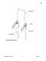
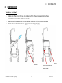
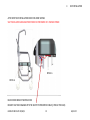
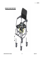
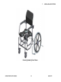
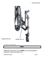
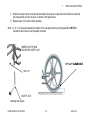
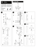
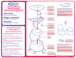
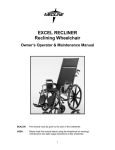
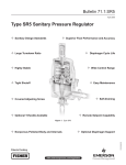
600 REV 02 REV DATE: 08/06/2013 NTF USER MANUAL CONTENTS 1 General.................................................................................................................................................................................................... 4 Operating Safety Warnings ..................................................................................................................................................... 5 Features ................................................................................................................................................................................... 6 Safety Inspection Checklist ...................................................................................................................................................... 7 Troubleshooting ...................................................................................................................................................................... 9 2 Arms ........................................................................................................................................................................................................ 9 REMOVING ARM ASSEMBLY .................................................................................................................................................... 9 INSTALLING ARM ASSEMBLY ................................................................................................................................................. 11 3 Back ....................................................................................................................................................................................................... 14 ADJUSTING BACK ASSEMBLY HEIGHT .................................................................................................................................... 16 4 Seat Installation .................................................................................................................................................................................... 18 TO INSTALL THE SEAT ............................................................................................................................................................ 18 Installing the Potty ................................................................................................................................................................ 20 5 Footrest ................................................................................................................................................................................................. 21 6 Casters .................................................................................................................................................................................................. 22 ADJUSTING COMMODE SEAT HEIGHT ................................................................................................................................... 22 Adjusting Commode Seat Height .......................................................................................................................................... 23 7 Rear wheels ........................................................................................................................................................................................... 24 REMOVING REAR WHEEL ...................................................................................................................................................... 24 600 REV02 REV DATE: 08/06/13 2 AQUA NTF CONTENTS USING THE WHEEL LOCKS – SELF PROPELLED ONLY ............................................................................................................. 26 ADJUSTING THE PATIENT OPERATED WHEEL LOCKS ............................................................................................................. 26 INSTALLING/ADJUSTING THE ANTI-TIPPERS .......................................................................................................................... 28 8 Cleaning and maintenance .................................................................................................................................................................... 30 600 REV02 REV DATE: 08/06/13 3 AQUA NTF 1 1 GENERAL General NOTICE: Information contained within this document is subject to change without notice. WARNING: DO NOT install this equipment without first reading and understanding this instruction booklet. If you are unable to understand these instructions, contact a healthcare professional, dealer or technical personnel before attempting to install this equipment - otherwise, injury or damage may occur. NOTE: Check all parts for shipping damages before using. In case of damage, DO NOT uses the equipment. Contact the Equipment Supplier for further instructions. 600 REV02 REV DATE: 08/06/13 4 AQUA NTF 1 GENERAL Operating Safety Warnings Please read and obey all instructions and warnings listed in this manual, ignoring these warnings could result in serious injury to the patient or attendants. NEVER LIFT THE WHEELCHAIR BY THE ARMRESTS OR FRONT RIGGING. ALWAYS TEST THE STABILITY OF THE CHAIR BEFORE USE. NEVER STAND ON THE FOOTPLATES DURING TRANSFERS IN AND OUT OF THE COMMODE. ENSURE WHEEL LOCKS ARE FULLY ENGAGED WHILE STOPPED ON ANY INCLINE/DECLINE AND WHILE PATIENT IS TRANSFERRING TO THE COMMODE, OR WHILE TRANSFERING FROM THE COMMODE. NEVER USE THE CASTER LOCKS TO STOP OR SLOW DOWN A MOVING WHEELCHAIR. IT IS NOT RECOMMENDED TO TRANSPORT USERS IN VEHICLES OF ANY KIND WHILE SEATED IN THE WHEELCHAIR. DO NOT USE ANY KIND OF WHEELCHAIR TIE-DOWN RESTRAINTS THAT ARE NOT APPROVED BY THE FDA. DO NOT LEAN FORWARD WHILE SITTING IN THE COMMODE DO NOT LEAN OVER THE COMMODE EDGE DO NOT ATTEMPT TO PICK UP OBJECTS FROM THE FLOOR DO NOT POSITION COMMODE ON THE SLOP DO NOT IMMERS COMMODE IN ANY LIQUID NOT SKILLED INDIVIDUALS MUST ASK FOR ASSISTANCE HELP DURING TRANSFER ONTO COMMODE, ALWAYS LOCK ALL FOUR CASTERS IN THEIR OUTWARD POSITION BEFORE TRANFER DO NOT TRANFER ONTO CHAIR ON SLIPPERY SURFACES DO NOT STAND ON COMMODE OR ANY PART OF COMMODE COMMODE IS NOT TRANSPORT CHAIR OR LONG TERM SEATING DEVICE IN CASE OF PROBLEMS DEALER CAN NOT RETURNED COMMODE UNTIL ALL MAINTANANCE OR ANY PROBLEMS ARE SOLVED. 600 REV02 REV DATE: 08/06/13 5 AQUA NTF 1 GENERAL Features FEATURES Seat Width 17" Seat Depth 17" Adjustable Height Back Slip on Back Support Seat to Floor Height 16.5" to 19.5" adj. without tools SPECIFICATIONS User Weight Limit 350 lb. Chair Width : 18”,20" or 22”. (with no armrests) Seat Depth 17”. Chair Length no Footrest: 22". Chair Height: 38" to 41”. Chair Weight: 55 Lbs. (Without front riggings). on Attendent Propelled w/4 casters Casters 5" - Total Lock - Stainless Steel Cantilever Fixed Height Arm Supports Removable Seat Removable Pan Support Removable Pan with lid Choice of 2 finishes - white powdercoat or electropolish 600 REV02 REV DATE: 08/06/13 6 AQUA NTF 1 GENERAL Safety Inspection Checklist 600 REV02 REV DATE: 08/06/13 7 X Monthly X X X X X X X X X X X X X Periodically Item GENERAL Wheelchair rolls straight (no excessive drag or pull to one side) FRAME AND CROSSING TUBES Inspect for loose or missing hardware Inspect for bent frame or cross-tubes CASTER LOCKS Caster locks easy to engage Caster locks prevent chair from moving when engaged SEAT AND BACK Inspect for rips or sagging Inspect for loose or broken hardware Inspect cane for wear/looseness FRONT CASTERS/FORKS Inspect caster fork assembly for proper tension by spinning caster; caster should come to a gradual stop Adjust bearing system if wheel wobbles or binds to a stop. Ensure wheel bearings are clean and free of moisture. Weekly Initially Initial adjustments should be made to suit your personal body structure needs and preference. Thereafter follow these maintenance procedures: X X X X X AQUA NTF X X 1 Check stem caster journal and lock nut for tightness Inspect casters for cracks and wear X X CLEANING Clean seat backrest and armrests X GENERAL X X X Please Note: Visual inspection of all parts for any deformation,corrosion,breakage.Check all fasteners on a regular basic to ensure that all connections remain secure. 600 REV02 REV DATE: 08/06/13 8 AQUA NTF 1 GENERAL X 2 Looseness in Chair X X Squeaks and Rattles X Caster Flutter Sluggish Turn or Performance Chair Veers Right/Left Troubleshooting X X Solutions Check for loose nuts and bolts Check a caster assembly Arms WARNING After ANY adjustments, repair or service and BEFORE use, make sure all attaching hardware is tightened securely – otherwise injury or damage may occur. REMOVING ARM ASSEMBLY 1. Lift the arm latch up with index finger such that the arm assembly is able to rotate 2. Rotate the arm assembly upwards to the position show in the figure in lower right corner. 600 REV02 REV DATE: 08/06/13 9 AQUA NTF 2 ARMRESTS 3. At this point the arm assembly should come to a stop. Gently slide the arm assembly towards your body and you should be able to see the arm assembly out come from the arm pivot rod. 4. Do not force the arm assembly out as there a nylon spacer which acts as a guide for the arm while it is rotating and keeps the arm in place. Note: If the nylon spacer becomes damaged then it needs to be replaced because it could cause problems for the end user. ARM INSTALATION AND ADJUSTMENT MUST BE PERFORMED BY A TRAINED PERSON Right Arm Assembly Arm Stop Arm Latch Left Arm Assembly 600 REV02 REV DATE: 08/06/13 Removing Arm Assembly 10 AQUA NTF 2 ARMRESTS INSTALLING ARM ASSEMBLY 1. Orient the arm assembly in a manner such that the arm latch and arm pads are oriented away from the back frame as shown below 2. Gently slide the arm assembly onto the arm pivot rod until it comes to a stop. 3. One should notice that the space between the two metal plates on the arm body should line up with the nylon spacer. 4. Do not force the arm assembly inwards as there a nylon spacer which acts as a guide for the arm while it is rotating and keeps the arm in place. Note: If the nylon spacer becomes damaged then it needs to be replaced because it could cause problems for the end user. 5. Gently rotate the arm assembly downwards until the arm assembly comes to rest. One should hear a ‘click’ noise and notice that the back of the arm latch is engaged with the arm stop. 600 REV02 REV DATE: 08/06/13 11 AQUA NTF 2 ARMRESTS Left Arm Assembly Right Arm Assembly Arm Pivot Arm Stop Arm Latch Installing Arm Assembly After ANY adjustments, cleaning,repair or service and BEFORE use, make sure all attaching hardware is tightened securely – otherwise injury or damage may occur. 600 REV02 REV DATE: 08/06/13 12 AQUA NTF 2 ARMRESTS ARM ASSEMBLY ARM HAS TO SNAP IN SADDLE 600 REV02 REV DATE: 08/06/13 13 AQUA NTF 3 3 BACK Back WARNING After ANY adjustments, repair or service and BEFORE use, make sure all attaching hardware is tightened securely – otherwise injury or damage may occur. REPLACING THE BACK UPHOLSTERY 1. Gently grasp the back upholstery from the sides and slide the upholstery up the back assembly until the upholstery becomes loose and is independent from the commode. 2. Gently grasp the new back upholstery from the sides and slide the upholstery down the back assembly until the top of the upholstery lines up with the top of the back assembly. One should also notice that the bends at the top of the back assembly should be visible through the cutouts on either side of the back upholstery. 600 REV02 REV DATE: 08/06/13 14 AQUA NTF 3 Back Upholstery Back Assembly Replacing Back Upholstery 600 REV02 REV DATE: 08/06/13 15 AQUA NTF BACK 3 BACK ADJUSTING BACK ASSEMBLY HEIGHT 1. Remove the snap clip on both sides of the back assembly 2. Adjust the position of the back assembly to the desired height on the receiver post and hold the back assembly in place. 3. Place the snap clip back into the back assembly to secure the assembly to the receiver post. Ensure the hole used by the snap clip is at the same position on both sides such that the back assembly is straight and not at an angle. 600 REV02 REV DATE: 08/06/13 16 AQUA NTF 3 Back Assembly Snap Clip Receiver Post Commode Frame Adjusting Back Assembly Height 600 REV02 REV DATE: 08/06/13 17 AQUA NTF BACK 4 4 SEAT INSTALLATION Seat Installation TO INSTALL THE SEAT 1. 2. 3. Slide the rear of the seat over the rear cross tube as the front of the seat is lowered onto the frame Rear brackets have to hook on welded nests on tube Lower the front of the seat until the front seat brackets nestle onto the front support cross tubes. Check to make sure that all brackets are engaged and put in safety pins (4 pc.) HOOK IT 600 REV02 REV DATE: 08/06/13 18 NEST IT SET SAFETY PINS ON BOTH SIDES AQUA NTF 4 SEAT INSTALLATION AFTER EVERY SEAT INSTALLATION CHECK FOR LOOSE SCREWS SEAT INSTALLATION AND ADJUSTMENT MUST BE PERFORMED BY A TRAINED PERSON DETAIL A DETAIL A BACK HOOKED BRACKET SHOWN IN RED BRACKET HAS TO BE ENGAGED WITH THE SAFETY PIN PRESENTED IN BLUE;(2 PINS AT THE BACK) 600 REV02 REV DATE: 08/06/13 19 AQUA NTF 4 SEAT INSTALLATION Installing the Potty 1. 2. Removal of the potty is achieved by sliding the Potty rearward from the chair Reinserting potty is achieved by pushing the potty into the wire slider until it’s fully positioned and engaged POTTY HAS TO SLIDE INSIDE WIRE BRACKET 600 REV02 REV DATE: 08/06/13 20 AQUA NTF 5 5 FOOTREST Footrest 1. 2. 3. 4. Remove the front rigging assembly. Loosen the 1/4-20 x 1/2” socket head button screw which fastens the footrest hanger to the footrest stem. Slide the footrest stem up or down to desired height. There should be approximately 2-3/8” of range for the footrest extension. Re-tighten socket head button screw. Repeat this procedure with the other footplate assembly. 600 REV02 REV DATE: 08/06/13 21 AQUA NTF 6 6 CASTERS Casters After ANY adjustments, cleaning,repair or service and BEFORE use, make sure all attaching hardware is tightened securely – otherwise injury or damage may occur. The Tente casters used on the commode have a unique locking mechanism which is located in each wheel. The mechanism allows the casters to be independently locked in place so that the commode does not move. In most instances one has to only the front two casters for the attendant propelled version and use the rear wheel locks on the self propelled version. ADJUSTING COMMODE SEAT HEIGHT 1. Remove the two snap clips located on the frame front 2. Adjust the position of the caster assembly to the desired height and hold the caster assembly in place. 3. Place the snap clip back into the frame front to secure the caster assembly to the frame. Ensure the hole used by the snap clip is at the same position on both sides such that the frame is straight and not at an angle. 4. Remove the two snap clips located on the frame back 5. Adjust the position of the caster assembly to the same position as the front casters and hold the casters in place. 6. Place the snap clips back into the frame back to secure the caster assembly to the frame. Ensure the hole used by the snap clip is at the same position on both sides such that the frame is straight and not at an angle. Note: When the height of the commode is changed one must ensure that the commode is stable and that one wheel is not higher or lower than another which could cause problems for the end user. 600 REV02 REV DATE: 08/06/13 22 AQUA NTF 6 Adjusting Commode Seat Height 600 REV02 REV DATE: 08/06/13 23 AQUA NTF CASTERS 7 7 WHEELS AND ANTI-TIPPERS Rear wheels After ANY adjustments, cleaning,repair or service and BEFORE use, make sure all attaching hardware is tightened securely – otherwise injury or damage may occur. REMOVING/INSTALLING THE REAR WHEELS WARNING If unmounting,changing the size of the rear wheel or a change in the seat-to-floor height is desired, this procedure MUST be performed by a qualified technician. REMOVING REAR WHEEL 1. 2. 3. 4. 5. 6. Use a wrench to remove the 7/16-20 lock nut holding the rear wheel in place. Gently pull the 7/16-20 x 4-1/2” bolt out from the bearings located in the rear wheel. To reinstall the rear wheel onto the commode, reverse steps 1 to 2. Repeat this procedure for the other rear wheel assembly if required. Ensure there is no instability in the rear wheel when it is spun. Ensure that the wheel lock shoe engages properly onto the wheel. Please refer to the section ADJUSTING THE PATIENT OPERATED WHEEL LOCKS. 600 REV02 REV DATE: 08/06/13 24 AQUA NTF 7 WHEELS AND ANTI-TIPPERS Removing/Installing Rear Wheels 600 REV02 REV DATE: 08/06/13 25 AQUA NTF 7 WHEELS AND ANTI-TIPPERS USING THE WHEEL LOCKS – SELF PROPELLED ONLY WARNING DO NOT attempt to stop a moving commode with the wheel locks. WHEEL LOCKS ARE NOT BRAKES – otherwise injury or damage may occur. 1. Ensure the commode is not moving before engaging the wheel locks. 2. Perform one (1) of the following: Push-to-Lock – to engage, push the wheel lock handle forward 3. Disengage the wheel locks by reversing STEP 2. ADJUSTING THE PATIENT OPERATED WHEEL LOCKS 1. Disengage the wheel locks. 2. Loosen the two (2) 1/4-20 x 1-1/2” socket screws shown in the below figure that secure the wheel lock to the commode frame. 3. Reposition the wheel lock so that when engaged, the wheel lock brake shoe embeds the tire 1/8” (3/16” for pneumatic tires) and HOLDS the occupied commode in place when pushed. 4. Securely tighten the two (2) 1/4-20 X 1-1/2” socket screws securing the wheel lock to the commode frame. 5. Engage the wheel lock. 6. Measure the distance the wheel lock is embedded into the tire 7. Repeat STEPS 1 to 6 until the wheel lock brake shoe embeds the tire and HOLDS the occupied commode in place when pushed. Engage both wheel locks and ensure the occupied commode is held in place when pushed. 600 REV02 REV DATE: 08/06/13 26 AQUA NTF 7 Adjusting Rear Wheel Locks WHEELS AND ANTI-TIPPERS 2 SCREWS 1/4-20 x 1-1/2” ANTI-TIPPERS – SELF PROPELLED ONLY WARNING After ANY adjustments,repair cleaning or service and BEFORE use, make sure all attaching hardware is tightened securely – otherwise injury or damage may occur. 600 REV02 REV DATE: 08/06/13 27 AQUA NTF 7 WHEELS AND ANTI-TIPPERS INSTALLING/ADJUSTING THE ANTI-TIPPERS WARNING Anti-tippers are specific to the different seat-to floor angles and/or seat-to-floor heights for self propelled commodes only. Refer to the chart in this section of the manual for correct usage and adjustment. If these requirements CANNOT be achieved, DO NOT us the commode. Contact a qualified technician. If changing the seat-to-floor height with or without a change to seat-to-floor angle, the correct anti-tippers MUST be used to maintain a 1 ½“ to 2” ground clearance. Seat-to-floor angle of 3 degrees to 6 degrees: if so equipped, anti-tippers MUST be attached at all times. In as much as the anti-tippers are an option on this commode (you may order with or without the anti-tippers), Future Mobility Healthcare Inc. strongly recommends ordering the anti-tippers as a safeguard for the commode user. Anti-tippers MUST be fully engaged and snap clips fully protruding out of adjustment holes. Ensure both anti-tippers are adjusted to the same mounting hole. INSTALLING ANTI-TIPPERS 1. Insert the Anti Tip assembly into the bottom of the commode frame where the caster position is for the attendant propelled commode. 2. Line up the hole in the back of the frame with one of the holes on the anti tip assembly. 3. Measure the distance between the bottom of the anti-tipper wheels and the ground/floor. 4. If the distance between the bottom of the anti-tipper wheels and the ground/floor is not 1 ½ “ to 2”, adjust the location of the anti-tippers and line up another hole on the anti tip assembly with the hole in the back of the frame. 600 REV02 REV DATE: 08/06/13 28 AQUA NTF 7 WHEELS AND ANTI-TIPPERS 5. When the proper location of the anti tip assembly is found, push a snap clip into the frame hole and into the anti assembly to hold it in place. As shown in the figure below. 6. Repeat steps 1-5 for other anti-tip assembly. Note: A 1 ½ “ to 2” clearance between the bottom of the anti-tipper wheels and the ground/floor MUST be maintained at all times for self propelled commode. INSERT ANTI-TIP AND SECURE BY SAFETY CLIP 1 1/2” to 2” CLEARANCE ANTI-TIP SAFETY CLIP Installing Anti Tippers 600 REV02 REV DATE: 08/06/13 29 AQUA NTF 8 8 CLEANING AND MAINTENANCE Cleaning and maintenance Procedure for Cleaning After Each Use Commode Potty Remove the Commode Potty and empty its contents. Wash the potty with a multi-purpose disinfectant detergent. DO NOT USE HOT AIR FOR DRYING. Urethane Seat and Back Use a multipurpose disinfecting detergent to spray seat, scrub with soft brush to clean a dirt. Rinse well and dry by wiping with soft dry cloth. DO NOT USE HOT AIR FOR DRYING. For more detailed cleaning, remove the seat from commode chair. DO NOT IMMERSE the commode chair seat in water or cleaning detergent solution. 600 REV02 REV DATE: 08/06/13 30 AQUA NTF 8 CLEANING AND MAINTENANCE Procedure for Cleaning As Needed Frame, Armrest, Footrests and Other Components Spray the frame and components with multi-purpose disinfectant detergent, and scrub with soft brush. Rinse well and dry by wiping with soft dry cloth. DO NOT USE HOT AIR FOR DRYING. If needed, spray the frame and components with diluted (10 parts water to 1 part solution) calcium/lime removal solution, scrub with soft brush and rinse well with water, dry with soft dry cloth. DO NOT mix a calcium/lime remover with any other liquid or toxic fumes may result. It is recommended that the rinsing of Aqua Commodes components occur in a well-drained area with an industrial steam cleaner or a commercial pressure washer. Several times during year the chair and all components should be wiped down with a diluted calcium/lime removal solution. By wiping down with soft clothes after final rinse risk of mildew buildup will be minimized. IMPORTANT: DO NOT USE ABRASIVE POWDERS OR SCOURING PADS ON AQUA COMMODE DO NOT SUBMERGE COMMODE IN WATER RINSE AFTER CLEANING TO ENSURE THAT ANY SOAP OR DETERGENT RESIDUE IS REMOVED DO NOT USE CLEANING PRODUCTS WITHOUT CONSULTING THE PRODUCTS’ INSTRUCTIONS AND TAKING APROPRIATE PRECAUTIONS FOR HUMAN EXPOSURE TO CHEMICALS 600 REV02 REV DATE: 08/06/13 31 AQUA NTF Warranty Future Mobility Healthcare Inc. (“FMH”) warrants its Aqua Rehab Commode NTF Wheelchair to be free from defects in materials and workmanship for one (1) year from the date of purchase. The frame is warranted for the lifetime of the original purchaser/user. If within this warranty period the product shall be proven to be defective, such product shall be repaired or replaced, at FMH discretion. FMH’s sole obligation and your exclusive remedy under this warranty shall be limited to the repair and/or replacement of the product or its parts. This warranty does not include any labour or shipping charges incurred in replacement part installation or repair of any product. For warranty service, please contact the dealer from whom you purchased your FMH product. In the event you do not receive satisfactory warranty service, please write directly to FMH. Provide the dealer's name, address, model number, date of purchase and indicate the nature of the defect. DO NOT return products to FMH without our prior consent. The defective unit or parts must be returned for warranty inspection within thirty (30) days of the return authorization date. (FMH will issue a return authorization number). Please prepay all shipping charges; C.O.D. shipments will be refused. LIMITATIONS and EXCLUSIONS: This warranty shall not apply to problems arising from normal wear or failure to adhere to the enclosed instructions. Products subjected to negligence, accident, improper usage, maintenance or storage; or products modified without FMH written consent including, but not limited to: modification through the use of any unauthorized parts or attachments; products damaged by reason or repairs made to any component without the specific consent of FMH, or products repaired by anyone other than a FMH dealer. Such evaluation shall be determined by FMH. The foregoing warranty is exclusive and in lieu of all other expressed warranties. It shall not extend beyond the duration of the expressed warranty provided herein and the remedy for violations of any implied warranty shall be limited to repair or replacement of the defective product pursuant to the terms contained herein. FMH shall not be liable for any consequential or incidental damages whatsoever. This warranty shall be extended to comply with all state laws and requirements.