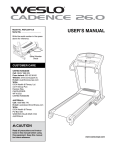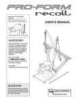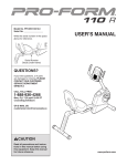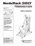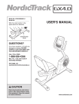
1
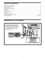
Model No. 15500C.0
Serial No.
Write the serial number in the space
above for reference.
Serial Number
Decal
ACTIVATE YOUR
WARRANTY
To register your product and
activate your warranty today,
contact Customer Service.
CUSTOMER SERVICE
Call toll-free 1-888-936-4266
Mon.–Fri. 7:30 a.m.–4:30 p.m. ET
(excluding holidays)
or email us at
[email protected]
Please do not contact the store.
CAUTION
Read all precautions and instructions in this manual before using
this equipment. Keep this manual
for future reference.
USER’S MANUAL
TABLE OF CONTENTS
WARNING DECAL PLACEMENT . . . . . . . . . . . . . . . . . . . . . . . . . . . . . . . . . . . . . . . . . . . . . . . . . . . . . . . . . . . . . . . 2
IMPORTANT PRECAUTIONS . . . . . . . . . . . . . . . . . . . . . . . . . . . . . . . . . . . . . . . . . . . . . . . . . . . . . . . . . . . . . . . . . . 3
BEFORE YOU BEGIN. . . . . . . . . . . . . . . . . . . . . . . . . . . . . . . . . . . . . . . . . . . . . . . . . . . . . . . . . . . . . . . . . . . . . . . . 5
PART IDENTIFICATION CHART. . . . . . . . . . . . . . . . . . . . . . . . . . . . . . . . . . . . . . . . . . . . . . . . . . . . . . . . . . . . . . . . 6
ASSEMBLY . . . . . . . . . . . . . . . . . . . . . . . . . . . . . . . . . . . . . . . . . . . . . . . . . . . . . . . . . . . . . . . . . . . . . . . . . . . . . . . . 7
ADJUSTMENT . . . . . . . . . . . . . . . . . . . . . . . . . . . . . . . . . . . . . . . . . . . . . . . . . . . . . . . . . . . . . . . . . . . . . . . . . . . . 16
EXERCISE GUIDELINES . . . . . . . . . . . . . . . . . . . . . . . . . . . . . . . . . . . . . . . . . . . . . . . . . . . . . . . . . . . . . . . . . . . . 17
PART LIST. . . . . . . . . . . . . . . . . . . . . . . . . . . . . . . . . . . . . . . . . . . . . . . . . . . . . . . . . . . . . . . . . . . . . . . . . . . . . . . . 18
EXPLODED DRAWING. . . . . . . . . . . . . . . . . . . . . . . . . . . . . . . . . . . . . . . . . . . . . . . . . . . . . . . . . . . . . . . . . . . . . . 19
ORDERING REPLACEMENT PARTS . . . . . . . . . . . . . . . . . . . . . . . . . . . . . . . . . . . . . . . . . . . . . . . . . . Back Cover
LIMITED WARRANTY. . . . . . . . . . . . . . . . . . . . . . . . . . . . . . . . . . . . . . . . . . . . . . . . . . . . . . . . . . . . . . . Back Cover
WARNING DECAL PLACEMENT
This drawing shows the location(s) of the
warning decal(s). If a decal is missing
or illegible, see the front cover of this
manual and request a free replacement
decal. Apply the decal in the location
shown. Note: The decal(s) may not be
shown at actual size.
2
IMPORTANT PRECAUTIONS
WARNING:
To reduce the risk of serious injury, read all important precautions and
instructions in this manual and all warnings on your weight rack before using your weight rack.
ICON assumes no responsibility for personal injury or property damage sustained by or through the
use of this product.
1. It is the responsibility of the owner to ensure
that all users of the weight rack are adequately informed of all precautions.
and a maximum total weight of 610 lbs. (277
kg). Do not place more than 310 lbs. (141
kg), including a barbell and weights, on the
weight rests or on the spotters. Note: No
barbell or weight plates are included.
2. Before beginning any exercise program,
consult your physician. This is especially
important for persons over age 35 or persons with pre-existing health problems.
11. Use only an Olympic-length barbell with the
weight rack.
3. Use the weight rack only as described in this
manual.
12. When using a barbell with the weight rack,
always set the spotters on the weight rack
at the lowest height to which you want the
barbell to go.
4. The weight rack is intended for home use
only. Do not use the weight rack in a commercial, rental, or institutional setting.
5. Keep the weight rack indoors, away from
moisture and dust. Do not put the weight
rack in a garage or covered patio, or near
water.
13. When using the rip:60™ Suspended Body
Weight Trainer on the weight rack, place
a total of at least 90 lbs. (41 kg) of weight
plates on the two lowest storage posts on
the weight rack. In addition, make sure that
there is not a barbell on the weight rack.
6. Place the weight rack on a level surface, with
enough clearance around the weight rack to
mount, dismount, and use the weight rack.
14. Remove the dip frame and the rip:60
Suspended Body Weight Trainer before you
use the pull-up handles.
7. Inspect and properly tighten all parts regularly. Replace any worn parts immediately.
15. Always place the same amount of weight
on both ends of a barbell. While adding or
removing weight plates, always keep some
weight on both ends of the barbell to prevent
the barbell from tipping.
8. Keep children under age 12 and pets away
from the weight rack at all times.
9. Always wear athletic shoes for foot protection while using the weight rack.
16. Over exercising may result in serious injury
or death. If you feel faint or if you experience
pain while exercising, stop immediately and
cool down.
10. The weight rack is designed to support a
maximum user weight of 300 lbs. (136 kg),
3
Your new fitness equipment represents a significant investment
in your health. Protect your investment now from unexpected
mechanical or electrical failures for up to five years.
PLAN FEATURES
t
t
t
t
t
t
Protection for one to five years
Over 100 authorized repair centers
Highly trained repair technicians
A national toll-free repair hotline
Simple repair claim procedure
No claim forms
t
t
t
t
t
Easy enrollment
Fast, efficient repair anywhere in Canada
In-home repairs covered
Parts and labour covered
Mechanical and electrical failures covered
To protect your fitness equipment today, please
call Customer Care at 1-888-936-4266
Or, email us at [email protected]
4
™
BEFORE YOU BEGIN
Thank you for selecting the WEIDER PRO™ 500 L
rack. The versatile 500 L weight rack is designed to
develop every major muscle group of the upper body.
Whether your goal is to develop a shapely figure,
dramatic muscle size and strength, or a healthier cardiovascular system, the 500 L weight rack will help you
to achieve the specific results you want.
reading this manual, please see the front cover of this
manual. To help us assist you, note the product model
number and serial number before contacting us. The
model number and the location of the serial number
decal are shown on the front cover of this manual.
Before reading further, please review the drawing
below and familiarize yourself with the labeled parts.
For your benefit, read this manual carefully before
using the weight rack. If you have questions after
Pull-up Handle
Spotter
Storage Post
Dip Arm
Spotter
Length: 6 ft. 1 in. (185 cm)
Width: 5 ft. 3 in. (160 cm)
Height: 7 ft. 1 in. (216 cm)
5
PART IDENTIFICATION CHART
Use the drawings below to identify the small parts needed for assembly. The number in parentheses below each
drawing is the key number of the part, from the PART LIST near the end of this manual. The number following the
key number is the quantity needed for assembly. Note: If a part is not in the hardware kit, check to see if it
has been preassembled. Extra parts may be included.
M10 Washer
(37)–20
M10 Curved
Washer (46)–4
M6 x 20mm
Screw (41)–12
M10 x 50mm Screw (45)–10
M10 x 75mm Screw (43)–8
M10 x 70mm Screw (47)–4
M10 x 75mm Hex Screw (39)–12
M10 x 80mm Screw (42)–8
M10 x 130mm Screw (40)–4
6
ASSEMBLY
• Assembly requires three persons.
• To identify small parts, see page 6.
• Due to its weight and size, the weight rack should
be assembled in the location where it will be
used. Make sure that there is enough clearance
to walk around the weight rack as you
assemble it.
• In addition to the included tool(s), assembly
requires the following tool(s):
one adjustable wrench
one Phillips screwdriver
• Place all parts in a cleared area and remove the
packing materials. Do not dispose of the packing
materials until you finish all assembly steps.
Assembly may be easier if you have a set of
wrenches. To avoid damaging parts, do not use
power tools.
• Left parts are marked “L” or “Left” and right parts
are marked “R” or “Right.”
1. Call or email Customer Service (see the front
cover of this manual) today and register your
product.
1
• activates your warranty
• saves you time if you ever need to contact
Customer Service
• allows us to notify you of upgrades and offers
7
2. Identify the Right Base (1) and the Right Front
Upright (3). Orient the parts as shown.
2
Attach the Right Front Upright (3) to the Right
Base (1) with two M10 x 75mm Hex Screws (39)
and two M10 Washers (37); do not tighten the
Screws yet.
3
1
37
37
3. Identify the Right Center Upright (5), and orient it
as shown.
39
3
Attach the Right Center Upright (5) to the Right
Base (1) with two M10 x 75mm Hex Screws (39)
and two M10 Washers (37); do not tighten the
Screws yet.
5
1
37
37
39
8
4. Identify the Right Rear Frame (8), and orient it
as shown.
4
Attach the Right Rear Frame (8) to the Right
Base (1) with two M10 x 75mm Hex Screws (39)
and two M10 Washers (37); do not tighten the
Screws yet.
8
1
37
39
5. Identify one of the two Top Frames (6), and orient it as shown.
5
Slide the Top Frame (6) onto the upper end of
the Right Rear Frame (8). The Top Frame (6)
should rest on the Right Front Upright (3) and
the Right Center Upright (5).
8
6
5
3
9
6. Attach the Top Frame (6) to the Right Rear
Frame (8) and to the Right Center Upright (5)
with two M10 x 75mm Screws (43), two M10
Washers (37), and two Frame Spacers (29); do
not tighten the Screws yet.
6
43
37
37
29
29
43
Next, attach the Top Frame (6) to the Right Front
Upright (3) with two M10 x 75mm Screws (43)
and two M10 Washers (37); do not tighten the
Screws yet.
6
37
8
37
5
3
7. Press three Rear Frame Caps (27) onto the
Right Rear Frame (8).
7
8
27
27
27
10
8. If you plan to use Olympic weight plates (not
included) with the weight rack, slide an Olympic
Adapter (22) onto one of the storage posts on
the Right Rear Frame (8). Attach the Olympic
Adapter with an M10 x 50mm Screw (45) and an
Adapter Cap (28).
8
28
Attach two more Olympic Adapters (22) to the
Right Rear Frame (8) in the same way.
22
28
See the EXPLODED DRAWING on page 19.
Repeat steps 2–8 and assemble the Left Base
(2), the Left Front Upright (4), the Left Center
Upright (49), the Left Rear Frame (9), and the
other Top Frame (6) in the same way.
9. Attach the Lower Crossbar (11) between the
Right Rear Frame (8) and the Left Rear Frame
(9) with four M10 x 130mm Screws (40); do not
tighten the Screws yet.
8
22
45
28
9
40
8
40
11
9
40
40
11
10. Attach one of the two Upper Crossbars (14)
between the two Center Uprights (5, 49) with
four M10 x 80mm Screws (42); do not tighten
the Screws yet.
10
42
42
Attach the other Upper Crossbar (14)
between the Center Uprights (5, 49) in the
same way.
14
42
5
14
42
49
11. Orient the Pull-up Crossbar (7) and the two
Carriages (15) as shown.
11
15
Loosen and pull the Adjustment Knob (24) on
one of the Carriages (15), and slide the Carriage
onto the Pull-up Crossbar (7). Then, release
the Adjustment Knob into one of the adjustment
holes in the Pull-up Crossbar, and tighten the
Adjustment Knob.
7
Warning
Decal
Slide the other Carriage (15) onto the Pull-up
Crossbar (7) in the same way.
15
24
12
12. Orient the Pull-up Crossbar (7) and the
Carriages (15) as shown, and attach the Pull-up
Crossbar to the Top Frames (6) with four M10
x 70mm Screws (47) and four M10 Curved
Washers (46).
12
6
See steps 2–4, 6, and 8–10. Tighten all of the
Screws (39, 43, 42, and 40) used in these steps.
15
46
7
15
46
47
46
47
13. Attach a Dip Handle (13) to the Dip Arm (10) with
two M10 x 50mm Screws (45) and a Dip Arm
Cap (36).
46
13
13
Attach the other Dip Handle (13) in the same
way.
13
36
10
45
14. Attach an Armrest (16) to the Dip Arm (10) with
four M6 x 20mm Screws (41). Start all four
Screws, and then tighten them.
14
16
16
Attach the other Armrest (16) in the same
way.
10
41
13
15. Attach the Backrest (17) to the Dip Arm (10)
with four M6 x 20mm Screws (41). Start all four
Screws, and then tighten them.
15
41
10
17
16. Set the Dip Arm (10) on the posts on the Left
Front Upright (4). Make sure that the Dip Arm
is fully seated.
16
10
4
14
17. Set the two Spotters (18) on the Uprights (3,
4, 5, and 49) as shown. Make sure that both
Spotters are at the same height.
17
3
5
18
18
49
4
18. Make sure that all parts are properly tightened before the weight rack is used. Note: Extra parts may be
included. The use of all remaining parts will be explained in ADJUSTMENT, beginning on page 16.
15
ADJUSTMENT
The steps below explain how the weight rack can be adjusted. Make sure that all parts are properly tightened
each time the weight rack is used. Replace any worn parts immediately. The weight rack can be cleaned with a
damp cloth and a mild, non-abrasive detergent; do not use solvents to clean the weight rack.
ADJUSTING THE PULL-UP HANDLES
To adjust the position of a Pull-up Handle (12),
loosen and pull the Adjustment Knob (24) on the
Carriage (15), and slide the Carriage to the desired
position. Then, release the Adjustment Knob into
one of the adjustment holes in the Pull-up Crossbar
(7), and tighten the Adjustment Knob.
15
7
24
12
ADJUSTING THE SPOTTERS
Set the two Spotters (18) on the Uprights (3, 4, 5,
and 49) at the lowest point to which you want your
barbell (not included) to go. Make sure that both
Spotters are at the same height.
18
3
5
18
49
4
USING THE DIP ARM
To use the Dip Arm (10), slide it onto the posts on
the Left Front Upright (4). Make sure that the Dip
Arm is fully seated.
When you are not using the Dip Arm (10), remove
it and set it out of the way.
10
4
16
EXERCISE GUIDELINES
FOUR TYPES OF STRENGTH WORKOUTS
to determine the appropriate length of time for each
workout, and the numbers of repetitions and sets to
complete. Progress at your own pace and be sensitive
to your body’s signals. Follow each workout with at
least one day of rest.
Note: A “repetition” is one complete cycle of an
exercise, such as one sit-up. A “set” is a series of
repetitions.
Muscle Building—Work your muscles near their maximum capacity and progressively increase the intensity
of your exercise. Adjust the intensity level of an individual exercise as follows:
• Change the amount of resistance used.
• Change the number of repetitions or sets performed.
Warming Up—Start with 5 to 10 minutes of stretching and light exercise. A warm-up increases your body
temperature, heart rate, and circulation in preparation
for exercise.
Working Out—Include 6 to 10 different exercises in
each workout. Select exercises for every major muscle
group, emphasizing areas that you want to develop.
To give balance and variety to your workouts, vary the
exercises from workout to workout.
Use your own judgment to determine the amount of
resistance that is right for you. Begin with 3 sets of 8
repetitions for each exercise you perform. Rest for 3
minutes after each set. When you can complete 3 sets
of 12 repetitions without difficulty, increase the amount
of resistance.
Cooling Down—Finish with 5 to 10 minutes of stretching. Stretching increases the flexibility of your muscles
and helps to prevent post-exercise problems.
Toning—Tone your muscles by working them to a
moderate percentage of their capacity. Select a moderate amount of resistance and increase the number of
repetitions in each set. Complete as many sets of 15 to
20 repetitions as possible without discomfort. Rest for
1 minute after each set. Work your muscles by completing more sets rather than by using high amounts of
resistance.
EXERCISE FORM
Move through the full range of motion for each exercise and move only the appropriate parts of the body.
Perform the repetitions in each set smoothly and
without pausing. The exertion stage of each repetition should last about half as long as the return stage.
Exhale during the exertion stage of each repetition and
inhale during the return stroke. Never hold your breath.
Weight Loss—To lose weight, use a low amount of
resistance and increase the number of repetitions in
each set. Exercise for 20 to 30 minutes, resting for a
maximum of 30 seconds between sets.
Rest for a short period of time after each set:
• Muscle Building—Rest for three minutes after each
set.
• Toning—Rest for one minute after each set.
• Weight Loss—Rest for 30 seconds after each set.
Cross Training—Combine strength training and aerobic exercise by following this type of program:
• Strength training workouts on Monday, Wednesday,
and Friday.
• 20 to 30 minutes of aerobic exercise on Tuesday and
Thursday.
• One full day of rest each week to give your body time
to regenerate.
STAYING MOTIVATED
For motivation, keep a record of each workout. Write
the date, the exercises performed, the resistance used,
and the numbers of sets and repetitions completed.
Record your weight and key body measurements once
a month. To achieve good results, make exercise a
regular and enjoyable part of your life.
WORKOUT GUIDELINES
Familiarize yourself with the equipment and learn the
proper form for each exercise. Use your own judgment
17
PART LIST
Key No. Qty.
1
2
3
4
5
6
7
8
9
10
11
12
13
14
15
16
17
18
19
20
21
22
23
24
25
1
1
1
1
1
2
1
1
1
1
1
2
2
2
2
2
1
2
4
4
2
6
2
2
2
Model No. 15500C.0 R1013A
Description
Key No. Qty.
Right Base
Left Base
Right Front Upright
Left Front Upright
Right Center Upright
Top Frame
Pull-up Crossbar
Right Rear Frame
Left Rear Frame
Dip Arm
Lower Crossbar
Pull-up Handle
Dip Handle
Upper Crossbar
Carriage
Armrest
Backrest
Spotter
Spotter Insert
Carriage Bushing
Pull-up Handle Bracket
Olympic Adapter
Carriage Spacer
Adjustment Knob
Long Foam Grip
26
27
28
29
30
31
32
33
34
35
36
37
38
39
40
41
42
43
44
45
46
47
48
49
*
4
6
6
4
2
2
4
6
4
4
2
20
12
12
4
12
8
8
2
10
4
4
2
1
–
Description
Short Foam Grip
Rear Frame Cap
Adapter Cap
Frame Spacer
50mm Round Cap
32mm Round Cap
25mm Round Cap
Base Foot
Oval Cap
M10 x 20mm Screw
Dip Arm Cap
M10 Washer
M4 x 16mm Screw
M10 x 75mm Hex Screw
M10 x 130mm Screw
M6 x 20mm Screw
M10 x 80mm Screw
M10 x 75mm Screw
M10 x 28mm Screw
M10 x 50mm Screw
M10 Curved Washer
M10 x 70mm Screw
M10 Large Washer
Left Center Upright
User’s Manual
Note: Specifications are subject to change without notice. For information about ordering replacement parts, see
the back cover of this manual. If a part is missing, call 1-877-992-5999. *These parts are not illustrated.
18
Model No. 15500C.0 R1013A
EXPLODED DRAWING
34
38
43
37
33
37
3
6
42
39
1
42
38
5
43
37
29
33
17
46
28
45
47
45
28
40
22
22
22
38
39
28
37
45
39
32
30
34
37
33
45
14
15
7
48
23
15
16
47
12
41
11
27 44
35
24
20
27
27
13
32
8
24
16
25
13
36
26
46
26
20
21
14
30
31
35
41
41
10
34
33
38
39
4
31
37
38
43
37
29
37
43
6
49
2
33
39
37
27
42
27
27
39
38
19
37
33
18
9
34
22
22
22
19
18
28
28
28
45
45
45
40
19
19
ORDERING REPLACEMENT PARTS
To order replacement parts, please see the front cover of this manual. To help us assist you, be prepared to
provide the following information when contacting us:
• the model number and serial number of the product (see the front cover of this manual)
• the name of the product (see the front cover of this manual)
• the key number and description of the replacement part(s) (see the PART LIST and the EXPLODED
DRAWING near the end of this manual)
LIMITED WARRANTY
IMPORTANT: To protect your fitness equipment with an extended service plan, see page 4.
ICON of Canada, Inc. (ICON) warrants this product to be free from defects in workmanship and material,
under normal use and service conditions. Parts and labor are warranted for ninety (90) days from the date
of purchase.
This warranty extends only to the original purchaser (customer). ICON’s obligation under this warranty is
limited to repairing or replacing, at ICON’s option, the product through one of its authorized service centers.
All repairs for which warranty claims are made must be preauthorized by ICON. If the product is shipped
to a service center, freight charges to and from the service center will be the customer’s responsibility. If
replacement parts are shipped while the product is under warranty, the customer will be responsible for a
minimal handling charge. For in-home service, the customer will be responsible for a minimal trip charge.
This warranty does not extend to freight damage to the product. This warranty will automatically be voided
if the product is used as a store display model, if all instructions in this manual are not followed, if the product is abused or improperly or abnormally used, or if the product is used for commercial or rental purposes.
No other warranty beyond that specifically set forth above is authorized by ICON.
ICON is not responsible or liable for indirect, special, or consequential damages arising out of or in connection with the use or performance of the product; damages with respect to any economic loss, loss of
property, loss of revenues or profits, loss of enjoyment or use, or costs of removal or installation; or other
consequential damages of any kind. Some provinces do not allow the exclusion or limitation of incidental
or consequential damages. Accordingly, the above limitation may not apply to the customer.
The warranty extended hereunder is in lieu of any and all other warranties, and any implied warranties of
merchantability or fitness for a particular purpose are limited in their scope and duration to the terms set
forth herein. Some provinces do not allow limitations on how long an implied warranty lasts. Accordingly,
the above limitation may not apply to the customer.
This warranty provides specific legal rights; the customer may have other rights that vary from province
to province.
ICON of Canada, Inc., 900 de l’Industrie, St. Jérôme, QC J7Y 4B8
Part 354235 R1013A
Printed in China © 2013 ICON IP, Inc.