1
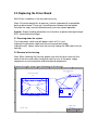
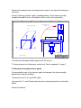
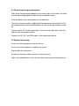
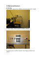
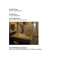
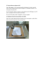
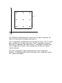
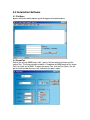
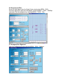
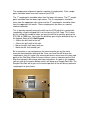
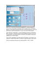
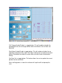
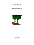
User’s Manual
PCB XYZ Drill Table
By
Bobby Trinh
Aaron Pakkalen
Robert Reed
Table Of Contents
1.0 Summary Statement .................................................................................................................................. 3
2.0 Replacing the Driver Board ...................................................................................................................... 4
2.1 Powering down the system................................................................................................................. 4
2.2 Removal of the housing ...................................................................................................................... 4
2.3 Removal of the bipolar driver board ................................................................................................ 5
2.4 Connecting the replacement board ................................................................................................... 6
2.5 Replace the housing ............................................................................................................................ 6
3.0 Mechanical Structure................................................................................................................................ 7
3.1 Drill Cage ............................................................................................................................................ 7
3.2 Power Supply - Micro Controller and Driver Housing................................................................... 7
3.2.1 Drill Power Switch....................................................................................................................... 8
3.2.2 20x2 Line LCD............................................................................................................................. 8
3.3.3 4x4 Keypad................................................................................................................................... 8
3.2.5 Intake Fan .................................................................................................................................... 9
3.2.6 DB9 Serial Communication ........................................................................................................ 9
3.2.7 Power Plug ................................................................................................................................... 9
3.2.8 Drill Plug .................................................................................................................................... 10
3.2.9 5A Fuse ....................................................................................................................................... 10
3.2.10 Outtake Fan ............................................................................................................................. 10
3.2.10 PCB Mounting Platform......................................................................................................... 10
4.0 Guideline for a automated PCB Drilling ................................................................................................ 11
4.1 Creating a Protel Drill file ............................................................................................................... 11
4.2 Mount Printed Circuit board .......................................................................................................... 11
4.3 Load software and power drill ........................................................................................................ 12
.4 Calibrate the drill to the position of the PCB................................................................................... 12
5.0 Automation Software.............................................................................................................................. 14
5.1 File Menu........................................................................................................................................... 14
5.2 CommPort ......................................................................................................................................... 14
5.3 Generate and Plot ............................................................................................................................. 15
5.4 Compensation Alignment................................................................................................................. 15
6.0 Rules to follow to ensure safe drilling operation .................................................................................... 19
6.1 DO NOT OPEN CASE WHILE THE POWER IS ON ................................................................. 19
6.2 DO NOT PLACE BODILY PARTS NEAR THE CAGE WHILE THE DRILL IS IN MOTION.
.................................................................................................................................................................. 19
6.3 USE PROTECTIVE EYE AND EAR PROTECTION.................................................................. 19
6.4 DO NOT LIFT THE DRILL TABLE ALONE.............................................................................. 19
6.5 DO NOT MOVE THE DRILL HORIZONTALLY WHILE DRILLING A HOLE................... 19
1.0 Summary Statement
The PCB XYZ drill table will drill all of the holes in a printed circuit board
automatically. To use the drill table, you must have a printed circuit board (PCB),
a PCB layout in Protel 99, and all of the drill bits required for the holes. There
are five parts to setup before you can let the drill work.
2.0 Replacing the Driver Board
Multi-Driver screwdriver is the only tool necessary.
Note: If the driver board fails to operate, it can be replaced with a compatible
back-up driver board. There are a few differences between the two boards
therefore the steps must be followed exactly to ensure correct operation.
Caution: Proper handling precautions must be taken to prevent damage through
ESD (electrostatic discharge).
2.1 Powering down the system
Turn main power switch and drill power switch off (if it is on).
Unplug the main power cable from the housing and wall socket.
Unplug the drill power cable from the housing. Unplug the DB9 cable from the
housing.
2.2 Removal of the housing
Note: When removing the housing, proper care must be taken to ensure that
none of the wires and cables hang up or catch on any of the power supply
components or micro-controller and driver board components.
Remove the eight screws from the bottom of the housing.
1
2
3
4
6
5
Removal of the housing
Step 2
D
D
Removal of the housing
Step 1
Remove 4 screws
C
C
Remove 8 screws
Bottom view of housing
B
B
PCB DRILL TABLE
A
Title
Appendix 1, Page 1
Size
B
Date:
File:
1
2
3
4
5
A
USERS MANUAL
Number
Revision
AARON PAKKALEN REV 00
16-Mar-2001
Sheet of
E:\DRILLT~1\AARON\REPORT\USERMA~1.SCH
Drawn By:
6
Remove the end panels by removing the two screws on the top of the housing at
each end.
Gently lift housing up while slightly spreading bottom. Lift the housing up high
enough to be able to access the boards inside as well as the connectors.
1
2
3
4
5
6
Removing the housing
D
Step 5
Removing the housing
Step 3
D
Tilt Housing up on end
C
C
Power Supply
B
B
Spread bottom slightly then tilt up
PCB DRILL TABLE
A
Title
Appendix 1, Page 2
Size
B
Date:
File:
1
2
3
4
5
A
USERS MANUAL
Number
Revision
AARON PAKKALEN
16-Mar-2001
Sheet of
E:\DRILLT~1\AARON\REPORT\USERMNL2.SCH
Drawn By:
REV 00
6
Unscrew the earth ground cable (green) from the chassis.
Tilt housing up on end (onto power socket end). Refer to appendix 1, page 2.
2.3 Removal of the bipolar driver board
Disconnect both ends of the interface cable that connects the micro-controller
board to the motor driver board.
Disconnect the 24V, 5V, and GND cables.
Unscrew the X, Y, and Z motor leads from the screw gate terminals on the driver
board.
Remove the board.
2.4 Connecting the replacement board
Note: Since the replacement board uses the center taps of the motors, the leads
must be connected properly in order for the new board to work.
Place the board in the same location as the old board.
Connect the interface cable (supplied with the replacement driver board) to the
driver board and the micro-controller board. Ensure that the pin numbers match
up.
Connect up the X, Y, and Z motor leads. Ensure that the lead colors match the
labels on the screw gate terminals.
Connect the 24V, 5V, and GND cables to the replacement board.
2.5 Replace the housing
Fasten the earth ground back onto the chassis.
Put the main housing back on. Replace the screws.
Replace both the end panels.
Re-connect the power cables and serial cable to the unit.
Note: If you followed these steps, the drill table should now be fully operational.
3.0 Mechanical Structure
3.1 Drill Cage
The drill cage is approximately a 60x60cm cube containing the drill assembly.
3.2 Power Supply - Micro Controller and Driver Housing
This housing houses the Micro-Controller, Power Supply and Motor Driver
circuitry.
3.2.1 Drill Power Switch
The drill power switch controls the power supplied to the Dremel Drill. A lamp is
used to indicate when the drill is switched on.
3.2.2 20x2 Line LCD
The 20x2 Line LCD (liquid crystal display) is used to provide feedback for the
user by providing the location of the drill.
3.3.3 4x4 Keypad
The 4x4 Keypad is for user input. The keypad allows the user to position the drill
anywhere on the platform.
Description of keypad functions:
- Moves the drill shaft to the left.
- Moves the drill shaft to the right.
- Moves the drill shaft away from you.
- Move the drill shaft toward you.
P – Pauses the drill movement.
S+ - Decreases the step speed by increasing the delay.
S- - Increases the step speed by decreasing the delay.
UP – Moves the Shaft up.
DN – Moves the Shaft down.
5 – make the movement to be 5 steps.
25 – make the movement to be 25 steps.
100 – make the movement to be 100 steps.
1000 – make the movement to be 1000 steps.
*Note a step is one stepper motor step.
3.2.4 Main Power Switch
The main power switch controls the power supplied to the main system.
3.2.5 Intake Fan
Blows cool air into the housing.
3.2.6 DB9 Serial Communication
Serial communications plug for external control.
3.2.7 Power Plug
Plug for powering the entire system.
3.2.8 Drill Plug
Power Plug for the drill.
3.2.9 5A Fuse
Fuse for protection.
3.2.10 Outtake Fan
Blows hot air out of the housing.
3.2.10 PCB Mounting Platform
Allows the user to securely mount their PCB prior to drilling.
4.0 Guideline for a automated PCB Drilling
4.1 Creating a Protel Drill file
Note: The drill does not have any sensors to detect where the holes are. This
information is taken directly from Protel. There are a few easy steps to making a
drill file.
Open the Protel Printed Circuit Board file. This is the same file that you used to
create the PCB.
Pull down “File” then click on CAM Manager. Protel should now open a CAM
output file.
Pull down “Edit”, then click on “Insert NC Drill”. Protel will pop up a window
labeled NC Drill Setup.
Make sure that the “Units” selection is “Millimeters”, then click ok.
Pull down “Tools” then click on “Generate CAM files”.
For more information on how to create PCB’s, schematics or drill files, refer to
the users manual for Protel 99.
4.2 Mount Printed Circuit board
Note: The drill can create some large forces on the printed circuit board. It is
important to secure the printed circuit board in place.
Inside the drill cage, loosen all four wing nuts.
Place the PCB towards the middle of the drill cage. Be sure that the PCB is not
overhanging the wood on any side. Also make sure that the front of the PCB is
facing up.
Place the two pieces of angle aluminum underneath the two pieces of square
aluminum. Do not take the square aluminum off its guides.
Position the angled aluminum on either side of the PCB. Over lap the edges of
the board, but be sure that the positions for the holes are not covered.
Replace the wing nuts and tighten until they are snug.
4.3 Load software and power drill
Note: When power is first turned on the drill will calibrate itself to the front left
corner. When facing the front of the Drill Cage this is the lower left corner. This
initial point will now be 0,0.
On a PC, load the software. Connect a serial cable from the COM port on the PC
to the serial port on the left side of the drill table.
Ensure that the power cable is plugged in, and turn on power.
4.4 Calibrate the drill to the position of the PCB
Note: Give the drill table the precise location of the 4 corner points, and it will be
able to calculate the position of the entire drill file.
Y
Sample 4
Sample 3
PCB Board
Sample 1
Sample 2
0,0
X
Drill Table
The PCB Board should be placed as square to the XY plane as possible. This
helps in the accuracy of the compensation process.
The 1st sample point should be taken from the lowest left corner. The 2nd sample
point should be from the lowest right corner. The 3rd sample point should be
taken from the uppermost right corner and the 4th sample point should be taken
from the uppermost left corner. These sample points are taken in a counter
clockwise direction.
Taking the sample points requires knowing how to used the Automation
Software. The following section 5.0 will show how to take sample points along
with a software description.
5.0 Automation Software
5.1 File Menu
Open a drill file for drilling. Open a log file for logging all communications.
5.2 CommPort
Adjust the settings 9600 baud, 8 bit, 1 parity. No flow control echo on and the
comm Port. The mico-controller module is hardwired for 9600 baud so this comm
Port has to be set to 9600. To open the comm Port, click on Port Open, this will
put a check beside the menu icon indicating the port is open.
5.3 Generate and Plot
Extract the data points from the Protel file by selecting the MENU - RUN –
Generate command. Open the Grid Map by selecting MENU – VIEW – GridMap
command. Plot the data points by selecting MENU – VIEW – Plot.
5.4 Compensation Alignment
Open the Calibration form by selecting MENU – RUN – Calibrate.
The compensation alignment requires sampling 4 sample points. Each sample
point should be taken near each corner of your PCB.
st
nd
The 1 sample point should be taken from the lowest left corner. The 2 sample
rd
point should be from the lowest right corner. The 3 sample point should be
th
taken from the uppermost right corner and the 4 sample point should be taken
from the uppermost left corner. These sample points are taken in a counter
clockwise direction.
This is done by manually moving the drill over the PCB hole that is going to be
sampled by using the keypad that is on the front of the Drill Cage. This is done
by first setting the number of steps you want the drill bit to move by pushing the
5,25,100, or 1000 keys. Next move the drill bit by pressing the directional keys of
the keypad. Refer to 4.1.3 4x4 Keypad.
- Moves the drill shaft to the left.
- Moves the drill shaft to the right.
- Moves the drill shaft away from you.
- Move the drill shaft toward you.
Be as accurate as you can because the more accurate you are the more
accurate the automation drilling will be. Once you have the drill bit over the
sample point, lock this value in by moving your mouse curser over the same hole
point on the Grid Map. When the mouse curser is over a hole point on the Grid
Map that hole point will change color from red to blue. As soon as this happens
you can click on the mouse button and this will bring up a Sample Point Box. The
Sample Point Box will let you set the current position of the drill bit to a particular
sample point of your choice.
You can move the drill bit up and down (Z Axis) by pressing the UP and DN
buttons on the keypad. Be careful not to over set the drill movement so that the
drill bit goes into the wood platform. This can cause the drill bit to break.
After setting the sample points, set the Drill depth by choosing a Z Reference
point. This point is the home position for up and down movement of the shaft.
The Step Size is the amount of offset. The offset is the amount of movement
added to the Z reference point.
Once all the sample points are taken and the Drill Depth is set then press the
Alignment Compensation button to calibrate the protel drill points to be drilled.
Start the automation drill process by selecting MENU – RUN – START.
Drill Change Enable/Disable is a toggle button. This will enable or disable the
prompting of the user to change drill bits when the different sizes of holes are
detected.
Shaft Move Enable/Disable is toggle button. This will enable or disable the up
and down movement of the shaft. This helps in doing a test run prior to an actual
drilling. Remember to enable this button when you want to do an automated
drilling.
Get Raw Val is a toggle button. This button allows the user to update the current
position into the text fields.
After a drilling process is done the software will stop the drill and prompt the
user.
6.0 Rules to follow to ensure safe drilling operation
6.1 DO NOT OPEN CASE WHILE THE POWER IS ON
There is a high voltage line entering the case, which can cause bodily harm or
loss of life.
6.2 DO NOT PLACE BODILY PARTS NEAR THE CAGE WHILE THE DRILL IS
IN MOTION.
The drill has a very sharp bit that is moving at high speed. It will not slow or stop
automatically if it starts to drill into your hand.
6.3 USE PROTECTIVE EYE AND EAR PROTECTION
The drill can be very loud which can be damaging to your hearing. There may
also be flying particles from the drill as the drill spins at very high speeds.
6.4 DO NOT LIFT THE DRILL TABLE ALONE
The drill table is quite heavy and awkward. At least two people should lift the
table.
6.5 DO NOT MOVE THE DRILL HORIZONTALLY WHILE DRILLING A HOLE
Drill bits are very fragile, and a sideways movement could easily shear off a bit.
Turn on drill before mounting project. The initial calibration sequence will drive
the drill bit to the front left corner. The drill will not stop if a mounting bracket is in
the way. It is also a good idea to mount the drill bit after mounting your project.