1
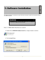
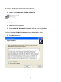
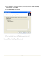
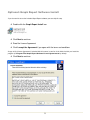
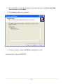
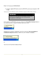
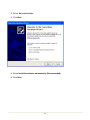
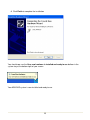
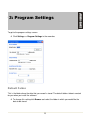
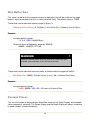
User Manual
Revision 1.0
MINi-DAS Standard User Manual
January 30, 2010
Revision 1.0
Copyright © 2010 CASE Technologies Ltd.
All Rights Reserved
Product Manufactured in Canada
The information in this manual has been checked carefully and is believed to be accurate; however, CASE
Technologies Ltd. assumes no responsibility for possible inaccuracies or omissions. Specifications are subject to
change without notice.
CASE Technologies Ltd. warrants this product to be free from defects in material or workmanship for 6 months
from the manufacturing date. The manufacturing date is encoded in the first six digits of your products serial
number. The warranty is limited to the original cost of the hardware and software only and does not cover
installation, labor, or any other contingent costs.
This software / hardware should not be used in any medical devices and/or medical situations. No software /
hardware provided by CASE Technologies Ltd. should be used in a life support situation.
Revision 1.0
Table of Contents
1: Software Installation ........................................................................................................... 1
Part 1: MINi-DAS Hardware Install......................................................................................... 1
Part 2: MINi-DAS Software Install .......................................................................................... 3
Optional: Graph Report Software Install................................................................................. 5
Part 3: Connect MINi-DAS ..................................................................................................... 7
2: MINi-DAS Introduction ...................................................................................................... 11
Default Folder ...................................................................................................................... 13
Rec. Interval......................................................................................................................... 14
Sample Interval .................................................................................................................... 14
Max Buffer Size.................................................................................................................... 15
Decimal Places .................................................................................................................... 15
4: Channel Settings ............................................................................................................... 16
Channel Description............................................................................................................. 16
Calibration............................................................................................................................ 17
Channel Alarms ................................................................................................................... 17
Gauge Settings .................................................................................................................... 19
Graph Settings ..................................................................................................................... 19
5: Calibration.......................................................................................................................... 21
Calibration Example ............................................................................................................. 21
Zero a Sensor: ..................................................................................................................... 23
6: Product Customization ..................................................................................................... 24
Custom Logo........................................................................................................................ 24
Custom Alarm ...................................................................................................................... 24
Revision 1.0
1:
1: Software
Software Installation
Installation
The software Installation is a 3 part process; please follow these instructions carefully to ensure proper operation
of the MINi-DAS system.
WARNING
All software must be installed on your computer BEFORE plugging in
the MINi-DAS hardware via the USB cable.
Part 1: MINi-DAS Hardware Install
Double Click the MINi-DAS Hardware Install Icon, to begin hardware installation.
Click the Install Button.
1
Your system will be scanned, and the proper drivers will be copied to your computer.
Click Continue Anyway when you see the warning screen
Click OK to finish the hardware installation.
Proceed to Part 2 MINi-DAS Software Install
2
Part 2: MINi-DAS Software Install
Double Click the MINi-DAS Software Install Icon
Click Next to continue
Read the License Agreement
Click I accept the Agreement if you agree with the terms and conditions
A copy of this License Agreement is included with this manual, as well as in the folder in which you install the
program. (C:\Program Files\MINi-DAS\Software License Agreement.txt by default)
Click Next to continue
3
If you would like a shortcut icon placed on your desktop select the Create a desktop
icon check box and click Next
Click Install to begin the installation
Once the Installer is done click Finish to complete the install
Proceed to Optional Graph Report Software Install
4
Optional: Graph Report Software Install
If you do not wish to use the included Graph Report software you can skip this step.
Double click the Graph Report Install icon
Click Next to continue
Read the License Agreement
Click I accept the Agreement if you agree with the terms and conditions
A copy of this License Agreement is included with this manual, as well as in the folder in which you install the
program. (C:\Program Files\Graph Report\Software License Agreement.txt by default)
Click Next to continue
5
If you would like a shortcut icon placed on your desktop select the Create a desktop
icon check box and click Next
Click Install to begin the installation
Once the Installer is done click Finish to complete the install
Proceed to Part 3 Connect MINi-DAS
6
Part 3: Connect MINi-DAS
Using the supplied USB cable, connect the MINi-DAS system to your computers’ USB
2.0 port.
You may use your own USB cable if you wish. The Maximum Length for a USB 2.0 Cable is 5 meters.
WARNING
The MINi-DAS system may not function properly if connected to a
USB Hub device. The MINi-DAS system should be directly
connected to a PC USB 2.0 port.
Once you plug in the MINi-DAS system you should see the Found New Hardware balloon in
the system tray, which is located in the bottom right of your screen.
Depending on or computers configuration, you will see either the Your new hardware is
installed and ready to use balloon (in which case your installation is complete)…
Or
You will see the Found New Hardware Wizard
7
Select No, not this time
Click Next
Select Install the software automatically (Recommended)
Click Next
8
Click Continue Anyway when the warning appears
9
Click Finish to complete the installation
You should now see the Your new hardware is installed and ready to use balloon in the
system tray at the bottom right of your screen.
Your MINi-DAS system is now installed and ready to use.
10
2: MINi-DAS Introduction
2: MINi-DAS Introduction
The MINi-DAS system is used as a real time display and data logger. You can display and log
up to 4 channels (depending on the model purchased) of instrument data, at one time.
The system is powered from the computers’ USB 2.0 port, so no external power supply is
required to run the MINi-DAS or the sensors connected to it. This makes the system much
simpler to setup, install, and use.
Main Display Screen
1: Menu Bar
2: Recording Indicator
3: High Alarm Override Indicator
4: Low Alarm Override Indicator
5: Graph Control Toggles
11
MINi-DAS Hardware
1: Channel Indicator
Green = OK
Red = Sensor/Cable Failure
Off = Channel Disabled
2: System Power/Communications Indicator
Red = System Powered
Flashing = Communication
Off = No System Power
3: USB 2.0 Port
4: PT02A-10-6S Channel Input (Mates with PT06(A,E,P,W)-10-6P)
Pin Out:
A: +24 Volts DC Out
B: Sig Return
C: NC
D: NC
E: NC (Can be connected to shield on request)
F: NC (Can be connected to shield on request)
12
3: Program Settings
3: Program Settings
To get to the program settings screen:
Click Settings >> Program Settings in the menu bar
Default Folder
This is the folder where the data that you record is stored. The default folder C:\Data is created
for you when you install the software.
To change this setting click Browse and select the folder in which you would like the
data to be stored.
13
When recording, all data is stored in a .csv (comma separated value) file, and this file is used
to create graph reports with the Graph Report program.
Rec. Interval
This is the interval (in milliseconds) in which the program will record data. The default setting is
1000ms, which means data will be recorded every 1 second.
Data is not recorded automatically, and you must start/stop recording manually. Refer to the Recording section
for more information.
Example:
If you wish to record data every 1 minute you would set this value to 60000
1000 milliseconds (1 second) X 60 seconds (1 minute) = 60000
The Recording Interval can not be lower than the Sample Interval as this would just record the same data more
than once.
Sample Interval
This is the interval (in milliseconds) in which the program requests sensor data from the
hardware, and then shows it on the screens displays (Gauge Display, Digital Display, and
Graph Display). The default setting is 500ms, which means the displays will update every 0.5
seconds
The Sample Interval is limited by the number of Channels you have activated. See below
Number of Active Channels
1
2
3
4
Maximum Sample Interval
125 milliseconds
250 milliseconds
375 milliseconds
500 milliseconds
These limits are in place to ensure proper communication between the software and the hardware. When you
have only one channel active it takes less time to Request-Sample-Report than it would if you had 4 channels
active.
14
Max Buffer Size
This value is used to set the maximum amount of data points that will be visible on the graph
before it starts to overwrite itself (this is called Historical Data). The default setting is 21600.
The formula used to calculate memory usage (in Bytes) is:
Number of Active Channels X 16 (Bytes) X Max Buffer Size = Memory Used (in Bytes)
Example:
Using the default settings
4 X 16 X 12600 = 806400 Bytes
To convert Bytes to Megabytes divide by 1048576:
806400 / 1048576 = 0.77 MB
WARNING
Do not set the Max Buffer Size to a value that is higher than your
available system memory, as this will cause an error.
The formula used to calculate how many hours of historical data the graph will hold is:
Max Buffer Size / (60000 / Sample Interval (in ms)) / 60 = Historical Data Hours
Example:
Using the default settings
12600 / (60000 / 500) / 60 = 3.5 hours of Historical Data
Decimal Places
This sets the number of decimal places that will be shown on the Digital Display, and recorded
(when recording is activated). The Gauge Display and the Graph Display will always show data
in whole numbers (no decimal places)
15
4:
4: Channel
Channel Settings
Settings
To get to the channel settings screen:
Click Settings >> Channel Settings in the menu bar
Channel Description
You can rename a channel to anything you wish, as well as set the units that you are
measuring i.e. PSI, MPA, DaN and so on.
16
Calibration
For proper calibration procedures, please see the Calibration section.
Raw Value:
This is a number, between 0 and 4096, that represents the raw signal
coming into the MINi-DAS on the selected channel.
Input Min/Max:
These values represent the min and max sensor input values, for instance
if you had a 4-20mA 0-15000psi sensor the Input Min value would
represent 4mA (Raw 819) and the Input Max value would represent 20mA
(Raw 4096).
For convenience, you will notice that when you select either the Input Min or Input Max value box, all of the text
in that box is highlighted, if you click the Insert button, the value showing in the Raw Value box will be copied to
the currently selected Input box.
Output Min/Max:
These values represent the scaled sensor output, for instance if you had a
4-20mA 0-15000psi sensor the Output Min value would be 0 and the
Output Max value would be 15000
Channel Alarms
Each Channel can have a High and Low Alarm, to enable either alarm:
Click the Enabled check box next to the corresponding alarm and enter a value in the
corresponding text box
Alarm logic is as follows:
High Alarm: If Input is Greater Than or Equal To High Alarm Value Then Active Alarm
Low Alarm: If Input is Less Than or Equal To Low Alarm Value Then Active Alarm
Once an Alarm becomes active, you will hear an audible alarm through the PC speakers, if
installed, and you will see the Active Alarm Screen.
If you purchased the Relay Option, the Internal Relay on the MINi-DAS hardware box will trip
on all active alarms, and reset once the alarm is cleared or overridden.
17
The Active Alarm Screen will indicate which channel the alarm is on and whether it is a High or
Low Alarm.
Click Clear to clear the Active alarm. (The alarm will appear again immediately if the
condition that tripped the alarm is still present)
Click Mute to mute the audible alarm
Click Override to ignore the alarm and all future alarms for that channel and alarm type
If you choose to override an alarm, an Override Alarm Indicator will be displayed on the Main
Display Screen (see MINi-DAS Introduction)
Click the High or Low Override Indicator (round red LED) on the Main Display Screen
to clear the override
The Clear Override Screen will be displayed to confirm.
18
Gauge Settings
Gauge Min/Max:
Change these values to set the minimum and maximum value of the
selected channels Gauge Display
Set Gauge Colors:
Under the Choose Item column Click the button of the item you wish to change
Click on a color
The changes will be updated on the sample gauge.
Graph Settings
Graph Min/Max:
Change these values to set the minimum and maximum value of the
Graph Display.
The graph will Auto Scale, so if your input is higher than the Graph Max the graph will automatically adjust itself.
19
Under the Choose Item column Click the button of the item you wish to change
Click on a color
The changes will be updated on the sample graph.
20
5: Calibration
5: Calibration
There are multiple ways to properly calibrate the MINi-DAS system, which are beyond the
scope of this manual. Some of these include:
•
•
•
Connecting a Process Simulator (i.e. Pressure pump & gauge) to the sensor.
Using the sensors shunt cal feature (if available)
Using a calibrator / multi-meter and the sensors calibration certificate.
To ensure proper MINi-DAS operation, calibration should only be performed by a trained technician.
To help explain the MINi-DAS calibration procedure, we will be using the last option listed
above as an example.
Calibration Example
Sensor Type: 0 to 15000 psi - 4 to 20 mA
Calibration Certificate Min:
0 psi = 4.01 mA
Calibration Certificate Max:
15000 psi = 20.02 mA
Setup:
21
On the Main Display Screen select Settings >> Channel Settings from the menu bar
Select the Channel you wish to calibrate (Channel 1 for our example)
Input Calibration Certificate Min. (4.01 mA for our example) on Calibrator
Select the Input Min box
Click Insert
Input Calibration Certificate Max. (20.02 mA for our example) on Calibrator
Select the Input Max box
Click Insert
Type your sensors Lower and Upper Range into the Output Min and Output Max boxes
This channel is now calibrated.
The Raw Values shown in the example are estimated. Various factors affect Raw Channel values such as
Temperature, Cable Length, and Sensor Type.
22
Zero a Sensor:
To quickly zero a sensor on any channel:
On the Main Display Screen select Settings >> Channel Settings on the menu bar
Select the Channel you wish to zero
Select the Input Min box
Click Insert
23
6: Product Customization
6: Product Customization
Custom Logo
You can change the logo that appears at the top left of the main display screen by:
Browse to the folder that you installed MINi-DAS into (C:\Program Files\MINi-DAS by
default)
Open the Resources folder and replace Logo.gif with your own. (Logo size 300 X 80)
Custom Alarm
You can change the Alarm that sounds when a High or Low alarm is activated by:
Browse to the folder that you installed MINi-DAS into (C:\Program Files\MINi-DAS by
default)
Open the Resources folder and replace alarm.wav with your own
24
LICENSE AGREEMENT
IMPORTANT - READ CAREFULLY: USE OF THIS PROGRAM IS SUBJECT TO THE SOFTWARE LICENSE TERMS SET
FORTH BELOW. "PROGRAM" INCLUDES ALL SOFTWARE INCLUDED WITH THIS AGREEMENT, THE ASSOCIATED
HARDWARE FIRMWARE, ANY PRINTED MATERIALS, AND ANY ONLINE OR ELECTRONIC DOCUMENTATION, AND
ANY AND ALL COPIES OF SUCH SOFTWARE AND MATERIALS. BY INSTALLING AND/OR USING THE PROGRAM AND
ANY SOFTWARE PROGRAMS INCLUDED WITHIN, YOU AND (IF APPLICABLE) YOUR COMPANY ACCEPTS THE
TERMS OF THIS LICENSE AGREEMENT WITH CASE TECHNOLOGIES LTD.
LIMITED USE LICENSE: CASE Technologies Ltd grants you the non-exclusive, non-transferable, limited right and license to
install and use one copy of this Program solely and exclusively for your and (if applicable) your companies use. All rights not
specifically granted under this Agreement are reserved by CASE Technologies Ltd and, as applicable, CASE Technologies Ltd
licensors. This Program is licensed, not sold. Your License confers no title or ownership in this Program. This License
Agreement shall also apply to any patches or updates you may obtain for the Program.
OWNERSHIP: All title, ownership rights and intellectual property rights in and to this Program (included but not limited to any
patches and updates) and any and all copies thereof are owned by CASE Technologies Ltd. This Program is protected by the
copyright laws of Canada, international copyright treaties and conventions and other laws. This Program contains certain
licensed materials and CASE Technologies Ltd licensors may protect their rights in the event of any violation of this
Agreement.
YOU SHALL NOT:
- Sell, rent, lease, license, distribute or otherwise transfer this Program, or any copies of this Program, without the express
prior consent of CASE Technologies Ltd.
- Reverse engineer, derive source code, modify, decompile, disassemble, or create derivative works of this Program, in whole
or in part.
-Remove, disable or circumvent any proprietary notices or labels contained on or within the Program
LIMITATION ON DAMAGES: IN NO EVENT WILL CASE TECHNOLOGIES LTD BE LIABLE FOR SPECIAL, INCIDENTAL
OR CONSEQUENTIAL DAMAGES RESULTING FROM POSSESSION, USE OR MALFUNCTION OF THE PROGRAM,
INCLUDING DAMAGES TO PROPERTY, LOSS OF GOODWILL, LOSS OF DATA, FINANCIAL LOSS, COMPUTER
FAILURE OR MALFUNCTION AND, TO THE EXTENT PERMITED BY LAW, DAMAGES FOR PERSONAL INJURIES, EVEN
IF CASE TECHNOLOGIES LTD HAS BEEN ADVISED OF THE POSSIBILITY OF SUCH DAMAGES. CASE
TECHNOLOGIES LTD'S LIABILITY SHALL NOT EXCEED THE ACTUAL PRICE PAID FOR THE LICENSE TO USE THIS
PROGRAM.
TERMINATION: Without prejudice to any other rights of CASE Technologies Ltd, this Agreement will terminate automatically if
you fail to comply with its terms and conditions. In such event, you must destroy all copies of this Program and all of its
component parts.
INJUNCTION: Because CASE Technologies Ltd would be irreparably damaged if the terms of this Agreement were not
specifically enforced, you agree that CASE Technologies Ltd shall be entitled, without bond, other security or proof of
damages, to appropriate equitable remedies with respect to breaches of this Agreement, in addition to such other remedies as
CASE Technologies Ltd may otherwise have under applicable laws.
INDEMNITY: You agree to indemnify, defend and hold CASE Technologies Ltd, its partners, affiliates contractors, officers,
directors, employees and agents harmless from all damages, losses, and expenses arising directly or indirectly from your acts
and omissions to act in using the Product pursuant to the terms of this Agreement
LIFE SUPPORT: THIS PROGRAM SHOULD NOT BE USED IN ANY MEDICAL DEVICES AND/OR MEDICAL SITUATIONS.
NO PRODUCT OR PROGRAM PROVIDED BY CASE TECHNOLOGIES LTD SHOULD BE USED IN A LIFE SUPPORT
SITUATION.
25