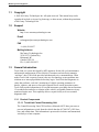
1
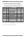
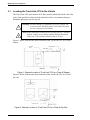
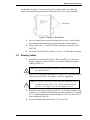
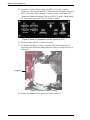
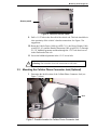
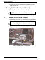
Installation Manual
Truck-Link
©2001 McCarney Technologies Inc.
McCarney Technologies Inc.
[This page is intentionally left blank.]
ii – Contents
Truck-Link Installation Manual
McCarney Technologies Inc.
CONTENTS
1
General Information..............................................................................................1
1.1 Copyright....................................................................................................2
1.2 Support .......................................................................................................2
1.3 General Introduction...................................................................................2
1.3.1 Product Components...........................................................................2
1.4 How This Manual Is Organized .................................................................3
1.5 Conventions Used in This Manual .............................................................4
1.6 Warranty, Liabilities, and Legal Statements ..............................................4
1.6.1 Disclaimer ...........................................................................................4
1.6.2 FCC .....................................................................................................4
1.6.3 Limited Warranty................................................................................4
1.6.4 Service Under Warranty .....................................................................5
1.6.5 Service Out of Warranty .....................................................................5
1.6.6 Extended Warranty .............................................................................5
2
Packaging and Handling Information .................................................................7
2.1 Part Numbers, Descriptions, Dimensions and Weights .............................8
2.2 Unpacking and Inspection ..........................................................................9
3
Installation Information ......................................................................................11
3.1 Locating the Truck-Link CPU in the Vehicle ..........................................12
3.2 Routing Cables .........................................................................................13
3.3 Mounting the Cellular Phone Connector Jack (Optional) ........................15
3.4 Mounting the Cellular Phone Handset (Optional)....................................16
3.5 Mounting the Driver Display (Optional)..................................................16
3.6 Mounting the GPS/Cellular Antenna .......................................................17
3.7 Connecting the Theft Detection Base Station (Optional).........................18
3.8 Connecting the Vehicle Power Cable.......................................................19
3.9 Initial Operational Test.............................................................................20
3.10 Setup of Cellular Phone............................................................................21
Truck-Link Installation Manual
Contents – iii
McCarney Technologies Inc.
LIST OF FIGURES
Figure 1: Desired Location of Truck-Link CPU in a Class 8 Sleeper .................................... 12
Figure 2: Desired Location of Truck-Link CPU in a Class 8 Day Cab .................................. 12
Figure 3: Details of Slide Mount ............................................................................................ 13
Figure 4: Detail of Connections on the Truck-Link CPU....................................................... 14
Figure 5: Details of Cable Routing ......................................................................................... 14
Figure 6: Data Bus Access Panel ............................................................................................ 15
Figure 7: Possible Location for Cellular Phone Connector Jack ............................................ 15
Figure 8: Possible Location of Driver Display ....................................................................... 16
Figure 9: GPS/Cellular Antenna ............................................................................................. 17
Figure 10: Possible Location of GPS/Cellular Antenna ......................................................... 17
Figure 11: Detail of Connections to Truck-Link CPU............................................................ 18
Figure 12: Anti-Theft Port Connection................................................................................... 18
Figure 13: Access Panel for Data Bus .................................................................................... 19
Figure 14: Vehicle Data Bus VMACIII.................................................................................. 20
Figure 15: Status Lights on the Truck-Link CPU................................................................... 20
LIST OF TABLES
Table 1: Parts List ..................................................................................................................... 8
Table 2: Connection Points and Sequence.............................................................................. 19
iv – Contents
Truck-Link Installation Manual
McCarney Technologies Inc.
1 GENERAL INFORMATION
This chapter covers the following topics:
•
Copyright Information
•
Contacts for Product Support
•
General Introduction
•
Organization of This Manual
•
Conventions Used in This Manual
•
Warranty Information
Truck-Link Installation Manual
General Information – 1
McCarney Technologies Inc.
1.1
Copyright
© 2001 McCarney Technologies Inc. All rights reserved. This manual may not be
reproduced in whole or in part, by photocopy or other means, without the permission
of McCarney Technologies Inc.
1.2
Support
Website
http://www.mccarneytechnologies.com
E-mail
[email protected]
FAX
+1 (604) 304-9937
Mailing Address
McCarney Technologies Inc.
2130-21331 Gordon Way
Richmond, BC
Canada V6W 1J9
Ph: +1 (604) 304-9933
1.3
General Introduction
Truck-Link is a system developed by MTI engineers for the life-cycle maintenance
and materials management of fleet vehicles. It monitors and wirelessly transmits
“real-time” data. Truck-Link provides both data and voice communications. What
makes Truck-Link a superior system is the use of technology to turn problems into
solutions or to intercept problems before they begin. Truck-Link has diagnostic circuitry that performs “real time” monitoring of vehicle operating parameters. It
detects, captures, and stores or forwards captured files to remote operation centers.
Truck-Link records information in 30-second increments, providing data on functions
15 seconds before and after a violation of the vehicle's acceptable parameters in any
monitored engine area. This capability allows a repair facility to access essential
diagnostic data.
1.3.1 Product Components
1.3.1.1 Truck-Link Central Processing Unit
The Central Processing Unit (CPU) utilizes a Motorola 68332 base processor to
process information received from the vehicle data bus (J1708/1587), GPS location, and cellular data. This information is processed in real-time and transmitted
wirelessly to a host computer.
2 – General Information
Truck-Link Installation Manual
McCarney Technologies Inc.
1.3.2.2.1 Backup Battery
A backup-battery is resident within Truck-Link’s central processing unit
and, in the event of a failure in the vehicle electrical circuitry, this battery
provides necessary power to the Truck-Link.
1.3.2.2.2 GPS Receiver
Included is a 12 channel Rockwell GPS receiver, which can locate any
vehicle anywhere in North America down to the block and the cross street.
1.3.2.2.2 Cellular Phone Transceiver
A three-watt Motorola analog cellular phone with the widest range available is part of the Truck-Link package. This phone provides a signal that is
5 to 7 times stronger than a conventional cell phone.
1.3.1.2 Cellular Phone Handset (Optional)
A standard Motorola handset, which has a large backlit display and a high-contrast display window, is used.
1.3.1.3 Driver Display (Optional)
The system provides a driver display digital message screen, on which a driver
can receive “real time” text directions to or through an unfamiliar location. It connects to the Truck-Link CPU with a 9-pin cable.
A further enhancement of the Driver Display is a button which can be used to signal the fleet base of an extraordinary event.
1.3.1.4 Theft Detection System (Optional)
Truck-Link’s add-on theft detection system is a small device that is easily
mounted out of sight on the vehicle. If the vehicle is moved in an unauthorized
manner, Truck-Link automatically alerts fleet dispatch.
Truck-Link is equipped with a GPS receiver, which enables fleet operations to
determine the vehicle’s exact geographical location, monitor its movement, and
direct police to intercept.
The Theft Detection module is activated/deactivated through the SnapShotHD
software. A back-up battery assures that even if the vehicle’s power is disconnected, Truck-Link will transmit the location to the base station.
1.3.1.5 GPS/Cellular Antenna
A low profile unitized antenna for both GPS and cellular communication can be
easily and quickly mounted on any vehicle
1.4
How This Manual Is Organized
This manual is divided into three sections. Section 1, General Information, provides
contact information, an overview of the Truck-Link system, a description of the conventions used in the manual, and warranty information.
Truck-Link Installation Manual
General Information – 3
McCarney Technologies Inc.
Section 2, Packing and Handling Information, provides a parts list and basic handling
information.
Section 3, Installation Information, outlines how to install and configure Truck-Link.
1.5
Conventions Used in This Manual
!
Warning: This symbol indicates important information about
product safety.
Caution: This symbol indicates important information about the
installer’s safety.
i
1.6
Note: This symbol indicates important information that may
improve the installation.
Warranty, Liabilities, and Legal Statements
1.6.1 Disclaimer
MTI makes no representations or warranties with respect to this manual. Further, MTI
reserves the right to make changes to the specifications of the product described
within this manual at any time without notice and without obligation of MTI to notify
any person of such revisions or changes.
1.6.2 FCC
“Warning: This equipment generates, uses, and can radiate radio frequency energy,
and if not installed in accordance with the instruction manual, may cause interference
to radio communications. It has been tested and found to comply with the limits for a
Class A computing device pursuant to Subpart J of Part 15 of FCC Rules, which are
designed to provide reasonable protection against such interference when operated in
a commercial environment. Operation of this equipment in a residential area is likely
to cause interference, in which case the user, at his own expense, will be required to
correct the interference.”
1.6.3 Limited Warranty
MTI hereby warrants its products to the immediate purchaser of this product, and to
no others in the line of commerce. Any other users, purchasers, or bystanders
involved with this product are expressly excluded from this warranty. MTI hereby
warrants its product for fitness for ordinary purposes for which such goods are used.
MTI warrants to the purchaser that each product manufactured to be delivered hereunder will be free from defects in material, workmanship, and title. MTI warrants that
each product manufactured will deliver the performance described in our sales literature, provided such product is properly cared for, and operated under normal conditions with knowledgeable supervision. The warranty is valid for a period of one year
from the date of shipment. If, within that time, the product delivered hereunder does
not meet the warranty specified above, the purchaser must notify MTI promptly.
4 – General Information
Truck-Link Installation Manual
McCarney Technologies Inc.
Thereupon, MTI shall correct any defect, either by repairing any defective part or
parts, or making available at MTI’s factory a repaired or replacement part. It will be
the sole decision of MTI as to which manner of correction shall be employed. Said
warranty extends only to the immediate purchaser and not the purchaser’s customers,
subsequent purchasers, bystanders, or any other person who may have contact with
MTI’s product.
In the event of any defective units, the liability of MTI hereunder shall be limited to
replacing or repairing any defective units, which are returned FOB. to MTI’s factory.
The option as to returning versus replacing the part shall be solely that of MTI.
Equipment or parts, which have been subject to abuse, misuse, accident, alterations,
neglect, unauthorized repair, or improper installation, are not covered by this warranty. MTI shall have the right of final determination as to the existence and cause of
any defects. In no case shall products be returned without first obtaining permission
from MTI prior to shipment. In the event of return or replacement of defective parts,
the warranty period shall be tolled for the duration of the return or repair. The warranty shall continue for the remainder of the original period, or for 30 days, upon date
of shipment by MTI to the purchaser.
In no event will MTI be liable for any incidental or consequential damages. If there
should be any liability found, it shall be limited to the original purchase price of the
product in question if said product is found to be defective. This warranty is in lieu of
all other warranties, whether expressed, implied, or statutory, including implied warranties of merchantability of fitness. There are no warranties that extend beyond the
description on the face hereof.
1.6.4 Service Under Warranty
If technical problems are experienced with your system, please call the MTI at
604.304.9933, or fax to 604.304.9937.
1.6.5 Service Out of Warranty
If your system is out of warranty, you should follow the same procedure when
requesting service of returned parts. You will be responsible for all parts, service, and
shipping costs. On-site service is available. Contact MTI for current rates. Should
your company require a purchase order for out-of-warranty repairs, inform your MTI
representative of that requirement during the initial call.
1.6.6 Extended Warranty
MTI offers an extended warranty contract. To take advantage of this extended warranty, you must sign the extended warranty contract and return it, together with full
payment to MTI prior to the end of your normal warranty period. The extended warranty period is one additional year. Shipping and labor charges are not included in the
extended warranty, and are the only expenses you incur during this period.
Truck-Link Installation Manual
General Information – 5
McCarney Technologies Inc.
[This page is intentionally left blank.]
6 – General Information
Truck-Link Installation Manual
McCarney Technologies Inc.
2 PACKAGING AND HANDLING INFORMATION
This chapter covers the following topics:
•
Part Numbers, Description, Dimensions and Weights
•
Unpacking and Inspection
Truck-Link Installation Manual
Packaging and Handling Information – 7
McCarney Technologies Inc.
2.1
Part Numbers, Descriptions, Dimensions and Weights
The Truck-Link system is shipped in one container. Table 1, below, describes the
parts which comprise the Truck-Link system (note that this list includes the optional
components). This list may be used as a checklist for the package contents.
Part Number
10-01-000
10-02-000
10-04-000/
10-04-001
10-01-100
20-03-000
MTI-C-10
MTI-C-2
MTI-C-11
Qty.
1
1
1
1
1
1
1
1
1
2
1
1
2
6
4
2
2
6
Description
Truck-Link CPU
Driver Display (Optional)
Cellular Handset (Optional)
Dimensions Weight
8”x11”x3”
4.5”x7.5”x1.5”
2”x8”
Antenna with Cable Attached
Theft Detection Device with
Attached Cable (Optional)
Theft Detection Badge (Optional)
Driver Display Connector Cable
Handset Extension Cable
Vehicle Power Cable
1 5/8”Bulkhead Grommet
¾” Black Wire Loom
¼” Black Wire Loom
Double-Sided Foam Tape
3/16”x1” Bolts
Pop Rivets to Mount Antenna
Screws to Mount Handset Cable
Jack
Screws to Mount Handset Cradle
Plastic Tie-Wraps
5”dia. 7.5”ht.
*
*
*
*
25’
25’
25’
n/a
20’
20’
2”
Table 1: Parts List
*
For security reasons, this information cannot be reproduced.
8 – Packaging and Handling Information
Truck-Link Installation Manual
McCarney Technologies Inc.
2.2
Unpacking and Inspection
In most cases, the system will not be completely unpacked and installed the day it
arrives at your facility.
i
Note: These unpacking and inspection instructions should be used
if you are checking the delivery of the goods without proceeding with the actual installation.
Open the shipping container and carefully remove each item. The table in section 2.1
can be used as a checklist and can also be used as a part identification sheet. If the
Truck-Link can be immediately installed in a truck, proceed to “Installation” (Section
3) of this manual.
i
Note: If there is any shipping damage to report, record it on the
shipping receipt, and notify MTI immediately.
Truck-Link Installation Manual
Packaging and Handling Information – 9
McCarney Technologies Inc.
[This page is intentionally left blank.]
10 – Packaging and Handling Information
Truck-Link Installation Manual
McCarney Technologies Inc.
3 INSTALLATION INFORMATION
This section covers the following tasks:
•
Locating the Truck-Link CPU in the Vehicle
•
Routing Cables
•
Mounting the Cellular Phone Connector Jack
•
Mounting the Cellular Phone Handset (Optional)
•
Mounting the Driver Display (Optional)
•
Mounting the GPS/Cellular Antenna
•
Connecting the Theft Detection Base Station (Optional)
•
Connecting the Vehicle Power Cable
•
Initial Operational Test
•
Setup of Cellular Phone (Optional)
Truck-Link Installation Manual
Installation Information – 11
McCarney Technologies Inc.
3.1
Locating the Truck-Link CPU in the Vehicle
The Truck-Link CPU, part number 10-01-000, must be installed inside the cab of the
truck. Some possible locations include under the bed in a conventional sleeper or
behind the passenger seat in a day cab
!
Warning: Possible damage to equipment can occur if unit is subjected to water. Mounting of the Truck-Link CPU must
be in a waterproof environment.
i
Note: When choosing a location for the Truck-Link CPU, consider
that the vehicle, driver display and the Handset Extension
cables are 25 feet and the antenna cable is 20 feet.
Figure 1, below, indicates the desired location of the Truck-Link CPU in a Class 8
sleeper.
Figure 1: Desired Location of Truck-Link CPU in a Class 8 Sleeper
Figure 2, below, indicates the desired location of the Truck-Link CPU in a Class 8
day cab.
Figure 2: Desired Location of Truck-Link CPU in a Class 8 Day Cab
12 – Installation Information
Truck-Link Installation Manual
McCarney Technologies Inc.
As illustrated in Figure 3, below, the Truck-Link is fitted with a moveable slide
mount. This unique feature allows the Trunk-Link CPU to be securely mounted
Figure 3: Details of Slide Mount
1 Once a location has been selected, temporarily secure the Truck-Link in
place and mark the attaching hole placement with a suitable marker.
2 Using a drill with a ¼” metal bit, drill the six holes to mount the TruckLink CPU.
3 Secure the Truck-Link CPU with the six 3/16” x 1” bolts and six locknuts.
3.2
Routing Cables
1 Carefully lay out the Vehicle Power Cable (p/n MTI-C-11), the Driver
Display Connector Cable (p/n MTI-C-10), and the Handset Extension
Cable (p/n MTI-C-2).
i
Note: The cable end with the part number identification connects to
the Truck-Link CPU.
2 Drill a 1 1/8” hole in the floorboard of the vehicle cab. This hole should be
near the Truck-Link CPU. See Figures 1 and 2 for suggestions.
i
Note: It is possible to route all cables under the carpet thereby preventing the need to drill a 1 5/8” hole in the floorboard of
the truck’s cab. Skip to step 5 if this method is chosen.
3 Route the Vehicle Power Cable (p/n MTI-C-11), the Driver Display Cable
(p/n MTI-C-10), and the Handset Extension Cable (p/n MTI-C-4), through
a 1 5/8” bulkhead grommet and then through the 1 5/8” hole that was cut
in the floorboard of the cab.
4 Secure the bulkhead grommet in the 1 5/8” access hole.
Truck-Link Installation Manual
Installation Information – 13
McCarney Technologies Inc.
5 Connect the Vehicle Power Cable (p/n MTI-C-11) to the “Vehicle”
Connector on the Truck-Link CPU. Connect the Driver Display Cable (p/n
MTI-C-10) to the “Driver Display” Connector on the Truck-Link CPU.
Connect the Handset Extension Cable (p/n MTI-C-4) to the “Phone Handset” Port on the Truck-Link CPU. See Figure 4, below.
Figure 4: Detail of Connections on the Truck-Link CPU
6 Insert the cables into the ¾” black wire loom.
7 As illustrated in Figure 5, below, route the cable loom forward to the
engine firewall. Secure the cables under the vehicle cab using wire ties or
equivalent.
Through hole
Figure 5: Details of Cable Routing
8 Remove the data bus access panel (see Figure 6, below).
14 – Installation Information
Truck-Link Installation Manual
McCarney Technologies Inc.
Access panel
Figure 6: Data Bus Access Panel
9 Drill a 1 1/8” hole in the firewall of the vehicle cab. This hole should be in
close proximity of the vehicle’s data bus connection. See Figure 5 for
suggestions.
10 Route the Vehicle Power Cable (p/n MTI-C-11), the Driver Display Cable
(p/n MTI-C-10), and the Handset Extension Cable (p/n MTI-C-4), through
a 1 5/8” bulkhead grommet and then through the 1 5/8” hole that was cut
in the floorboard of the cab.
11 Secure the bulkhead grommet in the 1 5/8” access hole.
!
3.3
Warning: Do not make electrical connections at this time.
Mounting the Cellular Phone Connector Jack (Optional)
1 Determine the ideal location of the Cellular Phone Connector Jack (see
Figure 7, below).
Jack
Figure 7: Possible Location for Cellular Phone Connector Jack
Truck-Link Installation Manual
Installation Information – 15
McCarney Technologies Inc.
2 Use two sheet metal screws (included) to securely mount the Cellular
Phone Connector Jack.
3.4
Mounting the Cellular Phone Handset (Optional)
1 Determine the ideal location of the Cellular Phone Handset.
i
Note: The driver must have easy access to the Handset.
2 Use four sheet metal screws (included) to securely mount the Handset.
3.5
Mounting the Driver Display (Optional)
1 Determine the ideal location of the Driver Display (see Figure 8, below).
i
Note: The driver must have easy access to the Driver Display. The
Drivers Display should not block access to other devices,
such as parking brakes, trailer brakes, radio, etc.
2 Use four sheet metal screws (included) to securely mount the Driver
Display.
Figure 8: Possible Location of Driver Display
16 – Installation Information
Truck-Link Installation Manual
McCarney Technologies Inc.
3.6
Mounting the GPS/Cellular Antenna
1 Determine the ideal location of the Antenna (illustrated in Figure 9,
below). An ideal location is on the top of the cab or sleeper (illustrated in
Figure 10, below).
Figure 9: GPS/Cellular Antenna
!
Warning: The GPS/Cellular Antenna must be mounted so that there
is no obstruction between it and the sky.
Antenna
Figure 10: Possible Location of GPS/Cellular Antenna
2 Drill four holes in the appropriate location on the vehicle’s cab.
3 Apply silicone sealant to all four holes.
4 Using the four pop-rivets (supplied), secure the antenna in place.
5 Apply silicone sealant to the top of each pop-rivet.
6 Insert the antenna cables into the ¼” black wire loom.
7 Secure cable harness loom to vehicle cab. Use P-clamps or plastic ties.
8 Route cable harness loom through the bulkhead grommet near the TruckLink CPU.
9 Connect the antenna cables to the Truck-Link CPU. (see Figure 11,
below).
Truck-Link Installation Manual
Installation Information – 17
McCarney Technologies Inc.
GPS Connection
Cellular Connection
Figure 11: Detail of Connections to Truck-Link CPU
10 Dress all cables.
3.7
Connecting the Theft Detection Base Station (Optional)
1 Determine the ideal location of the Theft Detection Base Station.
i
Note: When mounting the base station, an attempt should be made
to conceal the device. The cable is six (6’) feet in length and
is integrated into the base station.
2 Connect the Theft Detection Cable to the Truck-Link Theft Detection Port
(see Figure 12, below).
Anti-Theft Port
Figure 12: Anti-Theft Port Connection
3 Route cable to the base station mounting position.
4 Use the double-sided foam tape (included) to securely mount the base
station.
18 – Installation Information
Truck-Link Installation Manual
McCarney Technologies Inc.
3.8
Connecting the Vehicle Power Cable
1 Remove the Vehicle Data Bus Access Panel (see Figure 13, below).
Caution: The vehicle’s data bus connector has voltage applied
when the vehicle battery is connected. It is strongly
recommended that you disconnect the battery before
proceeding! Use extreme caution!
Access panel
Figure 13: Access Panel for Data Bus
Caution: To prevent damage to the vehicle and/or the Truck-Link
CPU ensure that the vehicle key is in the off position if
the vehicle battery is not disconnected.
2 See Table 2, below, for connection points and connection sequence.
Connection
Sequence
Wire Color
Vehicle Data Bus
Connection
Truck-Link Pin
Number
1
Green
“A” bus +
1
2
White
“B” bus -
2
3
Black
GND
3
4
Brown
“ING” Ignition
5
5
Red
“Batt” V+
4
Table 2: Connection Points and Sequence
3 Connect the Vehicle Power Cable to the Vehicle Data Bus. It is imperative
that the connection sequence as defined in Table 2 be followed. Figure 14,
below, illustrates a Vehicle Data Bus.
Truck-Link Installation Manual
Installation Information – 19
McCarney Technologies Inc.
Figure 14: Vehicle Data Bus VMACIII
4 Dress Vehicle Cable.
5 Install the Vehicle Data Bus Access Panel.
3.9
Initial Operational Test
1 Power (+12 volts) from the vehicle will be applied to the Truck-Link
CPU.
2 Observe L1, L2 and L3 on the connector end of the Truck-Link CPU (see
Figure 15, below).
Figure 15: Status Lights on the Truck-Link CPU
3 L1 will blink at a rate of twice per second.
4 L2 will blink at a rate of once per second.
5 L3 will be on steady.
20 – Installation Information
Truck-Link Installation Manual
McCarney Technologies Inc.
3.10 Setup of Cellular Phone
1 The cellular phone has been factory preset for your area and specific calling plan.
2 To place an outgoing call:
•
•
•
•
Press the ‘*’ key
Enter the ‘phone number’ you wish to call, including ‘1’ and the ‘area
code’.
Press the ‘SEND’ key
Press the ‘PWR’ key
For Example:
*→1→Area Code→7 digit phone number→‘SEND’→‘PWR’
Truck-Link Installation Manual
Installation Information – 21