1
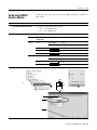
Logix5000™ Motion
Modules
1756 ControlLogix®,
1789 SoftLogix™
User Manual
Important User Information
Solid state equipment has operational characteristics differing from those of
electromechanical equipment. Safety Guidelines for the Application,
Installation and Maintenance of Solid State Controls (Publication SGI-1.1
available from your local Rockwell Automation sales office or online at
http://www.ab.com/manuals/gi) describes some important differences
between solid state equipment and hard-wired electromechanical devices.
Because of this difference, and also because of the wide variety of uses for
solid state equipment, all persons responsible for applying this equipment
must satisfy themselves that each intended application of this equipment is
acceptable.
In no event will Rockwell Automation, Inc. be responsible or liable for
indirect or consequential damages resulting from the use or application of
this equipment.
The examples and diagrams in this manual are included solely for illustrative
purposes. Because of the many variables and requirements associated with
any particular installation, Rockwell Automation, Inc. cannot assume
responsibility or liability for actual use based on the examples and diagrams.
No patent liability is assumed by Rockwell Automation, Inc. with respect to
use of information, circuits, equipment, or software described in this manual.
Reproduction of the contents of this manual, in whole or in part, without
written permission of Rockwell Automation, Inc. is prohibited.
Throughout this manual, when necessary we use notes to make you aware of
safety considerations.
WARNING
IMPORTANT
ATTENTION
Identifies information about practices or circumstances
that can cause an explosion in a hazardous environment,
which may lead to personal injury or death, property
damage, or economic loss.
Identifies information that is critical for successful
application and understanding of the product.
Identifies information about practices or circumstances
that can lead to personal injury or death, property
damage, or economic loss. Attentions help you:
• identify a hazard
• avoid a hazard
• recognize the consequence
SHOCK HAZARD
Labels may be located on or inside the equipment (e.g.,
drive or motor) to alert people that dangerous voltage may
be present.
BURN HAZARD
Labels may be located on or inside the equipment (e.g.,
drive or motor) to alert people that surfaces may be
dangerous temperatures.
Summary of Changes
Introduction
This release of this document contains new and updated information.
To find new and updated information, look for change bars, as shown
next to this paragraph.
Updated Information
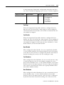
This document contains the following changes:
Change
Page
Quick start for setting up motion control
2-1
Make sure that your Kinetix 6000 drive has firmware revision 1.80 or
later if you want to use its auxiliary feedback port.
1
6-12, 10-10
Troubleshoot situations that are associated with S-Curve profiles
15-1
Inhibit an axis
16-1
Publication 1756-UM006G-EN-P - May 2005
Summary of Changes
2
Notes:
Publication 1756-UM006G-EN-P - May 2005
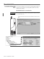
Preface
The Purpose of This Manual
Use this manual to setup and program motion control using a
Logix5000™ motion module.
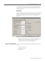
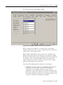
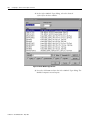
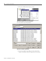
Related Documentation
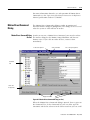
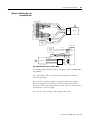
You are
here
To:
See:
get started with a Logix5000 controller
Logix5000 Controllers Quick Start, publication 1756-QS001
use a ControlLogix® controller
ControlLogix System User Manual, publication 1756-UM001
program a Logix5000 controller—detailed and
comprehensive information
Logix5000 Controllers Common Procedures, publication
1756-PM001
set up and program motion control
Logix5000 Motion Modules User Manaul, publication
1756-UM006
program a specific instruction
• Logix5000 Controllers General Instructions Reference
Manual, publication 1756-RM003
• Logix5000 Controllers Process and Drives Instructions
Reference Manual, publication 1756-RM006
• Logix5000 Controllers Motion Instructions Reference
Manual, publication 1756-RM007
• use equipment phases
PhaseManager User Manual, publication LOGIX-UM001
• set up a state model for your equipment
• program in a way that is similar to S88 and
PackML models
EtherNet/IP network—control devices
EtherNet/IP Modules in Logix5000 Control Systems User
Manual, publication ENET-UM001
ControlNet™ network—control devices
ControlNet Modules in Logix5000 Control Systems User Manual,
publication CNET-UM001
DeviceNet™ network—control devices
DeviceNet Modules in Logix5000 Control Systems User Manual,
publication DNET-UM004
import or export a Logix5000 project or tags from or
to a text file
Logix5000 Controllers Import/Export Reference Manual,
publication 1756-RM084
convert a PLC-5 or SLC 500 application to a
Logix5000 project
Logix5550 Controller Converting PLC-5 or SLC 500 Logic to
Logix5550 Logic Reference Manual, publication 1756-6.8.5
1756-M02AE module—install, wire, and
troubleshoot
Analog Encoder (AE) Servo Module Installation Instructions,
publication 1756-IN047
1756-M03SE module—install, wire, and
troubleshoot
ControlLogix SERCOS interface Module Installation Instructions,
publication 1756-IN572G-EN-P
1756-M08SE module—install, wire, and
troubleshoot
1756-M16SE module—install, wire, and
troubleshoot
1394C-SJTxx-D drive—install, wire, and set up
1
1394 SERCOS Interface Multi Axis Motion Control System,
publication 1394C-5.20
Publication 1756-UM006G-EN-P - May 2005
Preface
2
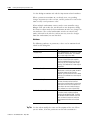
To:
See:
1394 drive with SERCOS—start up and troubleshoot 1394 SERCOS Integration Manual, publication 1394-IN024
Ultra3000 drive—install
Ultra3000 Hardware Installation Manual, publication 2098-IN003
Ultra3000 drive with SERCOS—start up and
troubleshoot
Ultra3000 SERCOS Integration Manual, publication 2098-IN005
Kinetix 6000 drive—design, install, and wire
Kinetix 6000 Installation Manual, publication 2094-IN001
Kinetix 6000 drive with SERCOS—start up and
troubleshoot
Kinetix 6000 Integration Manual, publication 2094-IN002
8720MC High Performance drive—use
8720MC High Performance Drive User Manual, publication
8720MC-UM001
Publication 1756-UM006G-EN-P - May 2005
Table of Contents
Chapter 1
The ControlLogix Motion Control
System
ControlLogix Motion Control . . . . . . . . . . . . . . . . . . . . . . . 1-1
Components of the ControlLogix Motion System . . . . . . . . 1-3
The ControlLogix Controller . . . . . . . . . . . . . . . . . . . . . 1-3
The Combo Module (1756-L60M03SE). . . . . . . . . . . . . . 1-3
The Analog/Encoder Servo Module (1756-MO2AE) . . . . 1-3
The Hydraulic Module (1756-HYD02) . . . . . . . . . . . . . . 1-4
The Synchronous Serial Interface (SSI) Module (1756-M02AS)
1-4
The 3, 8, or 16 Axis SERCOS interface Module (1756-M08SE,
1756-M16SE) . . . . . . . . . . . . . . . . . . . . . . . . . . . . . . . . 1-5
RSLogix 5000 Programming Software . . . . . . . . . . . . . . 1-5
Developing a Motion Control Application Program. . . . . . . 1-5
Application Program Development . . . . . . . . . . . . . . . . 1-6
The MOTION_INSTRUCTION Tag . . . . . . . . . . . . . . . . 1-6
Motion Status and Configuration Parameters . . . . . . . . . 1-7
Modifying Motion Configuration Parameters . . . . . . . . . 1-7
Handling Motion Faults . . . . . . . . . . . . . . . . . . . . . . . . 1-7
Chapter 2
Quick Start
Use This Chapter . . . . . . . . . . . . . . . . . . . . . . . . . .
Make the Controller the CST Master . . . . . . . . . . . . .
If you have more than 1 controller in the chassis
Add the Motion Modules . . . . . . . . . . . . . . . . . . . . .
Add SERCOS interface Drives . . . . . . . . . . . . . . . . .
Set Up Each SERCOS Interface Module . . . . . . . . . .
Add the Motion Group . . . . . . . . . . . . . . . . . . . . . .
Add Your Axes . . . . . . . . . . . . . . . . . . . . . . . . . . . .
Set Up Each Axis. . . . . . . . . . . . . . . . . . . . . . . . . . .
Check the Wiring of Each Drive. . . . . . . . . . . . . . . .
Tune Each Axis. . . . . . . . . . . . . . . . . . . . . . . . . . . .
Program Motion Control . . . . . . . . . . . . . . . . . . . . .
Additional Actions. . . . . . . . . . . . . . . . . . . . . . . . . .
.
.
.
.
.
.
.
.
.
.
.
.
.
.
.
.
.
.
.
.
.
.
.
.
.
.
.
.
.
.
.
.
.
.
.
.
.
.
.
.
.
.
.
.
.
.
.
.
.
.
.
.
.
.
.
.
.
.
.
.
.
.
.
.
.
2-1
2-2
2-2
2-3
2-4
2-5
2-6
2-8
2-9
2-12
2-13
2-14
2-16
Chapter 3
Adding and Configuring Your
1756-M02AE, 1756-M02AS,
1756-HYD02 Motion Module
1
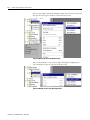
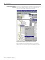
Adding the 1756-M02AE, 1756-HYD02, or 1756-M02AS Module
3-1
New Module . . . . . . . . . . . . . . . . . . . . . . . . . . . . . . . . 3-3
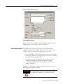
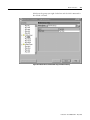
Editing Your Motion Module Settings . . . . . . . . . . . . . . . . . 3-7
General Tab . . . . . . . . . . . . . . . . . . . . . . . . . . . . . . . . 3-8
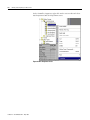
Connection Tab . . . . . . . . . . . . . . . . . . . . . . . . . . . . . . 3-10
Associated Axes Tab . . . . . . . . . . . . . . . . . . . . . . . . . . 3-13
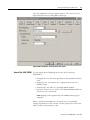
Module Info Tab . . . . . . . . . . . . . . . . . . . . . . . . . . . . . 3-14
Backplane Tab. . . . . . . . . . . . . . . . . . . . . . . . . . . . . . . 3-17
Assigning Additional Motion Modules . . . . . . . . . . . . . . . . 3-19
Publication 1756-UM006G-EN-P - May 2005
Table of Contents
2
Chapter 4
Configuring the 1756-M03SE,
1756-M08SE, or 1756-M16SE
Module
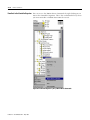
Adding the 1756-M03SE, 1756-M08SE, or 1756-M16SE . .
SERCOS interface Motion Module Overview. . . . . . . . .
Editing 1756-M03SE/-M08SE/-M16SE Module Properties
General Tab . . . . . . . . . . . . . . . . . . . . . . . . . . . . .
Connection Tab . . . . . . . . . . . . . . . . . . . . . . . . . . .
SERCOS Interface Tab . . . . . . . . . . . . . . . . . . . . . .
SERCOS Interface Info Tab . . . . . . . . . . . . . . . . . . .
Module Info Tab . . . . . . . . . . . . . . . . . . . . . . . . . .
Backplane Tab. . . . . . . . . . . . . . . . . . . . . . . . . . . .
.
.
.
.
.
.
.
.
.
.
.
.
.
.
.
.
.
.
.
.
.
.
.
.
.
.
.
4-1
4-6
4-8
4-8
4-10
4-13
4-15
4-16
4-19
.
.
.
.
.
.
.
.
.
.
.
.
.
.
.
5-1
5-4
5-5
5-6
5-8
Naming an Axis . . . . . . . . . . . . . . . . . . . . . . . . . . . . . . .
Entering Tag Information . . . . . . . . . . . . . . . . . . . . . .
Editing Motion Axis Properties. . . . . . . . . . . . . . . . . . . . .
General Tab – AXIS_SERVO . . . . . . . . . . . . . . . . . . . .
General Tab - AXIS_SERVO_DRIVE . . . . . . . . . . . . . .
General Tab - AXIS_VIRTUAL. . . . . . . . . . . . . . . . . . .
General Tab – AXIS_GENERIC . . . . . . . . . . . . . . . . . .
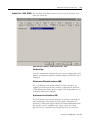
Motion Planner Tab . . . . . . . . . . . . . . . . . . . . . . . . . .
Units Tab. . . . . . . . . . . . . . . . . . . . . . . . . . . . . . . . . .
Servo Tab - AXIS_SERVO . . . . . . . . . . . . . . . . . . . . . .
Feedback Tab – (AXIS_SERVO) . . . . . . . . . . . . . . . . .
Drive/Motor Tab - (AXIS_SERVO_DRIVE) . . . . . . . . . .
Motor Feedback Tab - AXIS_SERVO_DRIVE . . . . . . . .
Aux Feedback Tab - AXIS_SERVO_DRIVE. . . . . . . . . .
Conversion Tab . . . . . . . . . . . . . . . . . . . . . . . . . . . . .
Homing Tab - AXIS_SERVO and AXIS_SERVO_DRIVE .
Homing Tab - AXIS_VIRTUAL . . . . . . . . . . . . . . . . . .
Hookup Tab - AXIS_SERVO . . . . . . . . . . . . . . . . . . . .
Hookup Tab Overview - AXIS_SERVO_DRIVE . . . . . .
Tune Tab - AXIS_SERVO, AXIS_SERVO_DRIVE . . . . . .
Dynamics Tab . . . . . . . . . . . . . . . . . . . . . . . . . . . . . .
Gains Tab - AXIS_SERVO . . . . . . . . . . . . . . . . . . . . . .
Gains Tab - AXIS_SERVO_DRIVE . . . . . . . . . . . . . . . .
Output Tab - AXIS_SERVO . . . . . . . . . . . . . . . . . . . . .
Output Tab Overview - AXIS_SERVO_DRIVE . . . . . . .
Limits Tab - AXIS_SERVO. . . . . . . . . . . . . . . . . . . . . .
.
.
.
.
.
.
.
.
.
.
.
.
.
.
.
.
.
.
.
.
.
.
.
.
.
.
6-1
6-3
6-5
6-7
6-9
6-14
6-15
6-18
6-21
6-22
6-25
6-30
6-37
6-38
6-40
6-42
6-47
6-48
6-51
6-53
6-56
6-59
6-65
6-72
6-76
6-80
Chapter 5
The Motion Group
Creating A Motion Group . . . . . . . .
Editing the Motion Group Properties
Axis Assignment Tab . . . . . . . . .
Attribute Tab . . . . . . . . . . . . . .
Tag Tab. . . . . . . . . . . . . . . . . . .
.
.
.
.
.
.
.
.
.
.
.
.
.
.
.
.
.
.
.
.
.
.
.
.
.
.
.
.
.
.
.
.
.
.
.
.
.
.
.
.
.
.
.
.
.
.
.
.
.
.
.
.
.
.
.
.
.
.
.
.
.
.
.
.
.
.
.
.
.
.
Chapter 6
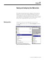
Naming and Configuring Your
Motion Axis
Publication 1756-UM006G-EN-P - May 2005
Table of Contents
Limits Tab - AXIS_SERVO_DRIVE . . . . .
Offset Tab - AXIS_SERVO. . . . . . . . . . . .
Offset Tab - AXIS_SERVO_DRIVE . . . . . .
Fault Actions Tab - AXIS_SERVO . . . . . .
Fault Actions Tab - AXIS_SERVO_DRIVE.
Tag Tab. . . . . . . . . . . . . . . . . . . . . . . . .
Assigning Additional Motion Axes . . . . . . . .
3
.
.
.
.
.
.
.
.
.
.
.
.
.
.
.
.
.
.
.
.
.
.
.
.
.
.
.
.
.
.
.
.
.
.
.
.
.
.
.
.
.
.
.
.
.
.
.
.
.
.
.
.
.
.
.
.
.
.
.
.
.
.
.
.
.
.
.
.
.
.
. 6-84
. 6-91
. 6-95
. 6-99
6-102
6-106
6-108
.
.
.
.
.
.
.
.
.
.
.
.
.
.
.
.
.
.
.
.
.
.
.
.
.
.
.
.
.
.
.
.
.
.
.
.
.
.
.
.
.
.
.
.
.
.
.
.
.
.
.
.
.
.
.
.
.
.
.
.
.
.
.
.
.
.
.
.
.
.
.
.
.
.
.
.
.
.
.
.
.
.
.
.
.
.
.
.
.
.
.
.
.
.
.
.
.
.
.
.
.
.
.
.
.
.
.
.
.
.
.
.
.
.
.
.
.
.
.
.
.
.
.
.
.
.
.
.
.
.
.
.
.
.
.
.
.
.
.
.
.
.
.
7-1
7-1
7-3
7-5
7-7
7-8
7-11
7-13
7-14
7-16
7-16
7-18
7-19
1394x-SJTxx-D Digital Servo Drive Overview .
General Tab . . . . . . . . . . . . . . . . . . . . . .
Connection Tab . . . . . . . . . . . . . . . . . . .
Associated Axes Tab . . . . . . . . . . . . . . . .
Power Tab . . . . . . . . . . . . . . . . . . . . . . .
Module Info tab. . . . . . . . . . . . . . . . . . . .
.
.
.
.
.
.
.
.
.
.
.
.
.
.
.
.
.
.
.
.
.
.
.
.
.
.
.
.
.
.
.
.
.
.
.
.
.
.
.
.
.
.
.
.
.
.
.
.
.
.
.
.
.
.
.
.
.
.
.
.
8-3
8-4
8-7
8-9
8-11
8-12
.
.
.
.
.
.
.
.
.
.
.
.
.
.
.
.
.
.
.
.
.
.
.
.
.
.
.
.
.
.
.
.
.
.
.
.
.
.
.
.
.
.
.
.
.
.
.
.
.
.
.
.
.
.
.
.
.
.
.
.
.
.
.
.
.
.
9-5
9-5
9-8
9-11
9-12
9-12
Editing the Kinetix Drive Properties . . . . . . . .
General Tab . . . . . . . . . . . . . . . . . . . . . .
Connection Tab . . . . . . . . . . . . . . . . . . . .
Associated Axes Tab (Kinetix 6000 Drives)
Power Tab - Kinetix Drive . . . . . . . . . . . .
.
.
.
.
.
.
.
.
.
.
.
.
.
.
.
.
.
.
.
.
.
.
.
.
.
.
.
.
.
.
.
.
.
.
.
.
.
.
.
.
.
.
.
.
.
. 10-4
. 10-4
. 10-7
10-10
10-11
Chapter 7
Creating & Configuring Your
Coordinate System Tag
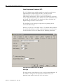
Introduction . . . . . . . . . . . . . . . . . . . . . .
Creating a Coordinate System . . . . . . . . .
Entering Tag Information . . . . . . . . . .
Coordinate System Wizard Screens . . .
Editing Coordinate System Properties. . . .
General Tab . . . . . . . . . . . . . . . . . . .
Units Tab. . . . . . . . . . . . . . . . . . . . . .
Dynamics Tab . . . . . . . . . . . . . . . . . .
Dynamics Tab Manual Adjust . . . . . . .
Tag Tab. . . . . . . . . . . . . . . . . . . . . . .
Tag Tab. . . . . . . . . . . . . . . . . . . . . . .
Right Mouse Click Properties . . . . . . . . . .
Cut, Copy, Paste, and Delete Behavior
.
.
.
.
.
.
.
.
.
.
.
.
.
.
.
.
.
.
.
.
.
.
.
.
.
.
Chapter 8
Configuring a 1394x-SJTxx-D
Digital Servo Drive
Chapter 9
Configuring an Ultra 3000 Drive
Editing the Ultra Drive Properties. . . . . . . .
General Tab . . . . . . . . . . . . . . . . . . . .
Connection Tab . . . . . . . . . . . . . . . . . .
Associated Axes Tab (Ultra3000 Drives)
Power Tab - Ultra Drive . . . . . . . . . . . .
Module Info Tab . . . . . . . . . . . . . . . . .
.
.
.
.
.
.
Chapter 10
Configuring a Kinetix 6000 Drive
Publication 1756-UM006G-EN-P - May 2005
Table of Contents
4
Module Info Tab . . . . . . . . . . . . . . . . . . . . . . . . . . . . 10-12
Chapter 11
Configuring an 8720MC Drive
Editing the 8720MC Drive Properties . . . .
General Tab . . . . . . . . . . . . . . . . . . .
Connection Tab . . . . . . . . . . . . . . . . .
Associated Axes Tab (8720MC Drives)
Power Tab - 8720MC Drive . . . . . . . .
Module Info Tab . . . . . . . . . . . . . . . .
.
.
.
.
.
.
.
.
.
.
.
.
.
.
.
.
.
.
.
.
.
.
.
.
.
.
.
.
.
.
.
.
.
.
.
.
.
.
.
.
.
.
.
.
.
.
.
.
.
.
.
.
.
.
.
.
.
.
.
.
.
.
.
.
.
.
.
.
.
.
.
.
. 11-5
. 11-5
. 11-8
11-11
11-12
11-12
Motion State Instructions . . . . . . . . . . . . . . .
Motion Move Instructions . . . . . . . . . . . . . .
Motion Group Instructions. . . . . . . . . . . . . .
Motion Event Instructions . . . . . . . . . . . . . .
Motion Configuration Instructions . . . . . . . .
Coordinated Motion Instructions . . . . . . . . .
Motion Direct Commands . . . . . . . . . . . . . .
Accessing Direct Commands . . . . . . . . . . . .
From the Main Menu . . . . . . . . . . . . . . .
From Group in the Controller Organizer .
From Axis in the Controller Organizer . .
Supported Commands . . . . . . . . . . . . . . . . .
Motion State . . . . . . . . . . . . . . . . . . . . .
Motion Move . . . . . . . . . . . . . . . . . . . . .
Motion Group . . . . . . . . . . . . . . . . . . . .
Motion Event . . . . . . . . . . . . . . . . . . . . .
Motion Direct Command Dialog . . . . . . . . .
Motion Direct Command Dialog On-line .
.
.
.
.
.
.
.
.
.
.
.
.
.
.
.
.
.
.
.
.
.
.
.
.
.
.
.
.
.
.
.
.
.
.
.
.
.
.
.
.
.
.
.
.
.
.
.
.
.
.
.
.
.
.
.
.
.
.
.
.
.
.
.
.
.
.
.
.
.
.
.
.
.
.
.
.
.
.
.
.
.
.
.
.
.
.
.
.
.
.
.
.
.
.
.
.
.
.
.
.
.
.
.
.
.
.
.
.
.
.
.
.
.
.
.
.
.
.
.
.
.
.
.
.
.
.
.
.
.
.
.
.
.
.
.
.
.
.
.
.
.
.
.
.
.
.
.
.
.
.
.
.
.
.
.
.
.
.
.
.
.
.
.
.
.
.
.
.
.
.
.
.
.
.
.
.
.
.
.
.
. 12-1
. 12-2
. 12-3
. 12-3
. 12-4
. 12-5
. 12-5
. 12-6
. 12-6
. 12-8
12-10
12-11
12-11
12-12
12-12
12-12
12-13
12-13
.
.
.
.
.
.
.
.
.
.
.
.
.
.
..........
..........
..........
..........
..........
..........
..........
..........
..........
..........
..........
Memory Use
..........
..........
Chapter 12
Motion Instructions
Chapter 13
Motion Object Attributes
Publication 1756-UM006G-EN-P - May 2005
Introduction . . . . . . . . . . . . . . . . .
Motion Object Interface Attributes .
Object Support Attributes . . . . .
Axis Structure Address . . . . . . .
Axis Instance . . . . . . . . . . . . . .
Group Instance . . . . . . . . . . . .
Map Instance . . . . . . . . . . . . . .
Module Channel . . . . . . . . . . .
Module Class Code . . . . . . . . .
C2C Map Instance . . . . . . . . . .
C2C Connection Instance . . . . .
........................
Memory Usage. . . . . . . . . . . . .
Axis Data Type . . . . . . . . . . . .
.
.
.
.
.
.
.
.
.
.
.
.
.
.
.
.
.
.
.
.
.
.
.
.
.
.
.
.
.
.
.
.
.
.
.
.
.
.
.
.
.
.
.
.
.
.
.
.
.
.
.
.
.
.
.
.
.
.
.
.
.
.
.
.
.
.
.
.
.
.
.
.
.
.
.
.
.
.
.
.
.
.
.
.
.
.
.
.
.
.
.
.
.
.
.
.
.
.
13-1
13-1
13-1
13-1
13-1
13-2
13-2
13-2
13-2
13-2
13-3
13-3
13-3
13-4
Table of Contents
Axis Configuration State . . . . . . . . . . . . .
Axis State . . . . . . . . . . . . . . . . . . . . . . .
Watch Event Task Instance. . . . . . . . . . .
Registration 1 Event Task Instance . . . . .
Registration 2 Event Task Instance . . . . .
Home Event Task Instance . . . . . . . . . . .
Motion Object Status Attributes . . . . . . . . . .
Motion Status Attributes . . . . . . . . . . . . .
Actual Position. . . . . . . . . . . . . . . . . . . .
Command Position. . . . . . . . . . . . . . . . .
Strobe Position . . . . . . . . . . . . . . . . . . .
Start Position . . . . . . . . . . . . . . . . . . . . .
Average Velocity . . . . . . . . . . . . . . . . . .
Actual Velocity. . . . . . . . . . . . . . . . . . . .
Command Velocity. . . . . . . . . . . . . . . . .
Actual Acceleration . . . . . . . . . . . . . . . .
Command Acceleration . . . . . . . . . . . . .
Watch Position. . . . . . . . . . . . . . . . . . . .
Registration Position. . . . . . . . . . . . . . . .
Registration Time . . . . . . . . . . . . . . . . . .
Interpolation Time . . . . . . . . . . . . . . . . .
Interpolated Actual Position . . . . . . . . . .
Interpolated Command Position . . . . . . .
Master Offset . . . . . . . . . . . . . . . . . . . . .
Strobe Master Offset. . . . . . . . . . . . . . . .
Start Master Offset . . . . . . . . . . . . . . . . .
Motion Status Bit Attributes . . . . . . . . . .
Motion Status Bits . . . . . . . . . . . . . . . . .
Axis Status Bit Attributes . . . . . . . . . . . .
Axis Fault Bit Attributes . . . . . . . . . . . . .
Module Fault Bit Attribute . . . . . . . . . . .
Axis Event Bit Attributes. . . . . . . . . . . . .
Output Cam Status . . . . . . . . . . . . . . . . .
Output Cam Pending Status . . . . . . . . . .
Output Cam Lock Status. . . . . . . . . . . . .
Output Cam Transition Status . . . . . . . . .
Motion Object Configuration Attributes . . . .
Axis Type . . . . . . . . . . . . . . . . . . . . . . .
Motion Planner Configuration Attributes .
Output Cam Execution Targets . . . . . . . .
Master Input Configuration Bits . . . . . . .
Master Position Filter Bandwidth . . . . . .
Motion Unit Configuration Attributes. . . .
Position Units . . . . . . . . . . . . . . . . . . . .
Average Velocity Timebase. . . . . . . . . . .
Motion Conversion Configuration . . . . . .
.
.
.
.
.
.
.
.
.
.
.
.
.
.
.
.
.
.
.
.
.
.
.
.
.
.
.
.
.
.
.
.
.
.
.
.
.
.
.
.
.
.
.
.
.
.
.
.
.
.
.
.
.
.
.
.
.
.
.
.
.
.
.
.
.
.
.
.
.
.
.
.
.
.
.
.
.
.
.
.
.
.
.
.
.
.
.
.
.
.
.
.
.
.
.
.
.
.
.
.
.
.
.
.
.
.
.
.
.
.
.
.
.
.
.
.
.
.
.
.
.
.
.
.
.
.
.
.
.
.
.
.
.
.
.
.
.
.
.
.
.
.
.
.
.
.
.
.
.
.
.
.
.
.
.
.
.
.
.
.
.
.
.
.
.
.
.
.
.
.
.
.
.
.
.
.
.
.
.
.
.
.
.
.
.
.
.
.
.
.
.
.
.
.
.
.
.
.
.
.
.
.
.
.
.
.
.
.
.
.
.
.
.
.
.
.
.
.
.
.
.
.
.
.
.
.
.
.
.
.
.
.
.
.
.
.
.
.
.
.
.
.
.
.
.
.
.
.
.
.
.
.
.
.
.
.
.
.
.
.
.
.
.
.
.
.
.
.
.
.
.
.
.
.
.
.
.
.
.
.
.
.
.
.
.
.
.
.
.
.
.
.
.
.
.
.
.
.
.
.
.
.
.
.
.
.
.
.
.
.
.
.
.
.
.
.
.
.
.
.
.
.
.
.
.
.
.
.
.
.
.
.
.
.
.
.
.
.
.
.
.
.
.
.
.
.
.
.
.
.
.
.
.
.
.
.
.
.
.
.
.
.
.
.
.
.
.
.
.
.
.
.
.
.
.
.
.
.
.
.
.
.
.
.
.
.
.
.
.
.
.
.
.
.
.
.
.
.
.
.
.
.
.
.
.
.
.
.
.
.
.
.
.
.
.
.
.
.
.
.
.
.
.
.
.
.
.
.
.
.
.
.
.
.
.
.
.
.
.
.
.
.
.
.
.
.
.
.
.
.
.
.
.
.
.
.
.
.
.
.
5
. 13-5
. 13-5
. 13-5
. 13-5
. 13-6
. 13-6
. 13-7
. 13-7
. 13-7
. 13-8
. 13-8
. 13-9
. 13-9
13-10
13-11
13-11
13-11
13-12
13-12
13-13
13-13
13-14
13-14
13-14
13-14
13-14
13-16
13-16
13-19
13-20
13-21
13-22
13-23
13-23
13-24
13-24
13-24
13-24
13-25
13-25
13-26
13-27
13-28
13-28
13-28
13-29
Publication 1756-UM006G-EN-P - May 2005
Table of Contents
6
Conversion Constant . . . . . . . . . . . . .
Rotary Axis . . . . . . . . . . . . . . . . . . . .
Position Unwind . . . . . . . . . . . . . . . .
Motion Homing Configuration . . . . . .
Home Mode . . . . . . . . . . . . . . . . . . .
Home Sequence and Home Direction .
Active Homing. . . . . . . . . . . . . . . . . .
Passive Homing . . . . . . . . . . . . . . . . .
Home Configuration Bits . . . . . . . . . .
Home Position. . . . . . . . . . . . . . . . . .
Home Offset . . . . . . . . . . . . . . . . . . .
Home Speed . . . . . . . . . . . . . . . . . . .
Home Return Speed. . . . . . . . . . . . . .
InhibitAxis. . . . . . . . . . . . . . . . . . . . .
Motion Dynamics Configuration . . . . .
Maximum Speed . . . . . . . . . . . . . . . .
Maximum Acceleration/Deceleration. .
Programmed Stop Mode. . . . . . . . . . .
Servo Status Attributes . . . . . . . . . . . . . . .
Position Command. . . . . . . . . . . . . . .
Position Feedback . . . . . . . . . . . . . . .
Aux Position Feedback. . . . . . . . . . . .
Position Error . . . . . . . . . . . . . . . . . .
Position Integrator Error . . . . . . . . . . .
Velocity Command. . . . . . . . . . . . . . .
Velocity Feedback . . . . . . . . . . . . . . .
Velocity Error . . . . . . . . . . . . . . . . . .
Velocity Integrator Error . . . . . . . . . . .
Acceleration Command . . . . . . . . . . .
Acceleration Feedback . . . . . . . . . . . .
Servo Output Level . . . . . . . . . . . . . .
Marker Distance. . . . . . . . . . . . . . . . .
Servo Status Bit Attributes. . . . . . . . . .
Servo Status Bit Attributes. . . . . . . . . .
Axis Control Bit Attributes . . . . . . . . .
Axis Response Bit Attributes . . . . . . . .
Servo Fault Bit Attributes . . . . . . . . . .
Module Fault Bit Attributes . . . . . . . . .
Attribute Error Code. . . . . . . . . . . . . .
Attribute Error ID. . . . . . . . . . . . . . . .
Commissioning Status Attributes . . . . .
Test Status . . . . . . . . . . . . . . . . . . . . .
Test Direction Forward. . . . . . . . . . . .
Test Output Direction . . . . . . . . . . . .
Tune Status . . . . . . . . . . . . . . . . . . . .
Tune Acceleration/Deceleration Time .
Publication 1756-UM006G-EN-P - May 2005
.
.
.
.
.
.
.
.
.
.
.
.
.
.
.
.
.
.
.
.
.
.
.
.
.
.
.
.
.
.
.
.
.
.
.
.
.
.
.
.
.
.
.
.
.
.
.
.
.
.
.
.
.
.
.
.
.
.
.
.
.
.
.
.
.
.
.
.
.
.
.
.
.
.
.
.
.
.
.
.
.
.
.
.
.
.
.
.
.
.
.
.
.
.
.
.
.
.
.
.
.
.
.
.
.
.
.
.
.
.
.
.
.
.
.
.
.
.
.
.
.
.
.
.
.
.
.
.
.
.
.
.
.
.
.
.
.
.
.
.
.
.
.
.
.
.
.
.
.
.
.
.
.
.
.
.
.
.
.
.
.
.
.
.
.
.
.
.
.
.
.
.
.
.
.
.
.
.
.
.
.
.
.
.
.
.
.
.
.
.
.
.
.
.
.
.
.
.
.
.
.
.
.
.
.
.
.
.
.
.
.
.
.
.
.
.
.
.
.
.
.
.
.
.
.
.
.
.
.
.
.
.
.
.
.
.
.
.
.
.
.
.
.
.
.
.
.
.
.
.
.
.
.
.
.
.
.
.
.
.
.
.
.
.
.
.
.
.
.
.
.
.
.
.
.
.
.
.
.
.
.
.
.
.
.
.
.
.
.
.
.
.
.
.
.
.
.
.
.
.
.
.
.
.
.
.
.
.
.
.
.
.
.
.
.
.
.
.
.
.
.
.
.
.
.
.
.
.
.
.
.
.
.
.
.
.
.
.
.
.
.
.
.
.
.
.
.
.
.
.
.
.
.
.
.
.
.
.
.
.
.
.
.
.
.
.
.
.
.
.
.
.
.
.
.
.
.
.
.
.
.
.
.
.
.
.
.
.
.
.
.
.
.
.
.
.
.
.
.
.
.
.
.
.
.
.
.
.
.
.
.
.
.
.
.
.
.
.
.
.
.
.
.
.
.
.
.
.
.
.
.
.
.
.
.
.
.
.
.
.
.
.
.
.
.
.
.
.
.
.
.
.
.
.
.
.
.
.
.
.
.
.
.
.
.
.
.
.
.
.
.
.
.
.
.
.
.
.
.
.
.
.
.
.
.
.
.
.
.
.
.
.
.
.
.
.
.
.
.
.
.
.
.
.
.
.
.
.
.
.
.
.
.
.
.
.
.
.
.
.
.
.
.
.
.
.
.
.
.
.
.
.
.
.
.
.
.
.
.
.
.
.
.
.
.
.
.
.
.
.
.
.
13-29
13-29
13-30
13-30
13-30
13-32
13-32
13-37
13-38
13-38
13-38
13-39
13-39
13-39
13-39
13-39
13-40
13-40
13-42
13-43
13-43
13-44
13-44
13-44
13-44
13-45
13-45
13-45
13-45
13-46
13-46
13-46
13-46
13-47
13-49
13-50
13-51
13-53
13-55
13-55
13-56
13-56
13-57
13-57
13-57
13-58
Table of Contents
Tune Acceleration/Deceleration . . .
Tune Speed Scaling . . . . . . . . . . . .
Tune Rise Time . . . . . . . . . . . . . . .
Tune Inertia. . . . . . . . . . . . . . . . . .
Servo Configuration Attributes . . . . . . .
Feedback Configuration . . . . . . . . .
Servo Feedback Type. . . . . . . . . . .
LDT Type . . . . . . . . . . . . . . . . . . .
LDT Recirculations . . . . . . . . . . . . .
LDT Calibration Constant . . . . . . . .
LDT Calibration Constant Units. . . .
LDT Scaling . . . . . . . . . . . . . . . . . .
LDT Scaling Units . . . . . . . . . . . . .
LDT Length . . . . . . . . . . . . . . . . . .
LDT Length Units. . . . . . . . . . . . . .
SSI Code Type . . . . . . . . . . . . . . . .
SSI Data Length . . . . . . . . . . . . . . .
SSI Clock Frequency . . . . . . . . . . .
SSI Overflow Detection . . . . . . . . .
Absolute Feedback Enable . . . . . . .
Absolute Feedback Offset. . . . . . . .
Servo Configuration . . . . . . . . . . . .
Servo Loop Configuration. . . . . . . .
External Drive Type . . . . . . . . . . . .
Fault Configuration Bits. . . . . . . . .
Axis Info Select . . . . . . . . . . . . . . .
Servo Polarity Bits . . . . . . . . . . . . .
Servo Loop Block Diagrams . . . . . .
Velocity Feedforward Gain . . . . . . .
Acceleration Feedforward Gain. . . .
Position Proportional Gain . . . . . . .
Position Integral Gain . . . . . . . . . .
Velocity Proportional Gain . . . . . . .
Velocity Integral Gain . . . . . . . . . .
Position Differential Gain . . . . . . . .
Velocity Scaling . . . . . . . . . . . . . . .
Torque Scaling. . . . . . . . . . . . . . . .
Directional Scaling Ratio. . . . . . . . .
Backlash Reversal Error . . . . . . . . .
Backlash Stabilization Window . . . .
Output LP Filter Bandwidth . . . . . .
Integrator Hold Enable. . . . . . . . . .
Servo Limits. . . . . . . . . . . . . . . . . .
Maximum Positive/Negative Travel .
Position Error Tolerance. . . . . . . . .
Position Lock Tolerance . . . . . . . . .
.
.
.
.
.
.
.
.
.
.
.
.
.
.
.
.
.
.
.
.
.
.
.
.
.
.
.
.
.
.
.
.
.
.
.
.
.
.
.
.
.
.
.
.
.
.
.
.
.
.
.
.
.
.
.
.
.
.
.
.
.
.
.
.
.
.
.
.
.
.
.
.
.
.
.
.
.
.
.
.
.
.
.
.
.
.
.
.
.
.
.
.
.
.
.
.
.
.
.
.
.
.
.
.
.
.
.
.
.
.
.
.
.
.
.
.
.
.
.
.
.
.
.
.
.
.
.
.
.
.
.
.
.
.
.
.
.
.
.
.
.
.
.
.
.
.
.
.
.
.
.
.
.
.
.
.
.
.
.
.
.
.
.
.
.
.
.
.
.
.
.
.
.
.
.
.
.
.
.
.
.
.
.
.
.
.
.
.
.
.
.
.
.
.
.
.
.
.
.
.
.
.
.
.
.
.
.
.
.
.
.
.
.
.
.
.
.
.
.
.
.
.
.
.
.
.
.
.
.
.
.
.
.
.
.
.
.
.
.
.
.
.
.
.
.
.
.
.
.
.
.
.
.
.
.
.
.
.
.
.
.
.
.
.
.
.
.
.
.
.
.
.
.
.
.
.
.
.
.
.
.
.
.
.
.
.
.
.
.
.
.
.
.
.
.
.
.
.
.
.
.
.
.
.
.
.
.
.
.
.
.
.
.
.
.
.
.
.
.
.
.
.
.
.
.
.
.
.
.
.
.
.
.
.
.
.
.
.
.
.
.
.
.
.
.
.
.
.
.
.
.
.
.
.
.
.
.
.
.
.
.
.
.
.
.
.
.
.
.
.
.
.
.
.
.
.
.
.
.
.
.
.
.
.
.
.
.
.
.
.
.
.
.
.
.
.
.
.
.
.
.
.
.
.
.
.
.
.
.
.
.
.
.
.
.
.
.
.
.
.
.
.
.
.
.
.
.
.
.
.
.
.
.
.
.
.
.
.
.
.
.
.
.
.
.
.
.
.
.
.
.
.
.
.
.
.
.
.
.
.
.
.
.
.
.
.
.
.
.
.
.
.
.
.
.
.
.
.
.
.
.
.
.
.
.
.
.
.
.
.
.
.
.
.
.
.
.
.
.
.
.
.
.
.
.
.
.
.
.
.
.
.
.
.
.
.
.
.
.
.
.
.
.
.
.
.
.
.
.
.
.
.
.
.
.
.
.
.
.
.
.
.
.
.
.
.
.
.
.
.
.
.
.
.
.
.
.
.
.
.
.
.
.
.
.
.
.
.
.
.
.
.
.
.
.
.
.
.
.
.
.
.
.
.
.
.
.
.
.
.
.
.
.
.
.
.
.
.
.
.
.
.
.
.
.
.
.
.
.
.
.
.
.
.
.
.
.
.
.
.
.
.
.
.
.
.
.
.
.
.
.
.
.
.
.
.
.
.
.
.
.
.
.
.
7
13-58
13-58
13-59
13-59
13-60
13-60
13-61
13-63
13-63
13-63
13-63
13-63
13-64
13-64
13-64
13-64
13-64
13-65
13-65
13-65
13-66
13-66
13-67
13-67
13-68
13-69
13-70
13-71
13-74
13-75
13-76
13-78
13-79
13-80
13-81
13-81
13-82
13-82
13-83
13-83
13-84
13-85
13-85
13-85
13-86
13-86
Publication 1756-UM006G-EN-P - May 2005
Table of Contents
8
Output Limit . . . . . . . . . . . . . . . . . . . . .
Direct Drive Ramp Rate . . . . . . . . . . . . .
Servo Offsets . . . . . . . . . . . . . . . . . . . . .
Friction Compensation . . . . . . . . . . . . . .
Friction Compensation Window . . . . . . .
Velocity Offset . . . . . . . . . . . . . . . . . . . .
Torque Offset . . . . . . . . . . . . . . . . . . . .
Output Offset . . . . . . . . . . . . . . . . . . . .
Servo Fault Configuration . . . . . . . . . . . .
Servo Fault Actions . . . . . . . . . . . . . . . .
Commissioning Configuration Attributes .
Test Increment. . . . . . . . . . . . . . . . . . . .
Tuning Travel Limit . . . . . . . . . . . . . . . .
Tuning Speed . . . . . . . . . . . . . . . . . . . .
Tuning Torque. . . . . . . . . . . . . . . . . . . .
Damping Factor . . . . . . . . . . . . . . . . . . .
Drive Model Time Constant . . . . . . . . . .
Velocity Servo Bandwidth . . . . . . . . . . .
Position Servo Bandwidth . . . . . . . . . . .
Tuning Configuration Bits . . . . . . . . . . .
Servo Drive Status Attributes . . . . . . . . . . . .
Drive Status Attributes . . . . . . . . . . . . . .
Position Command. . . . . . . . . . . . . . . . .
Position Feedback . . . . . . . . . . . . . . . . .
Aux Position Feedback. . . . . . . . . . . . . .
Position Error . . . . . . . . . . . . . . . . . . . .
Position Integrator Error . . . . . . . . . . . . .
Velocity Error . . . . . . . . . . . . . . . . . . . .
Velocity Integrator Error . . . . . . . . . . . . .
Velocity Command. . . . . . . . . . . . . . . . .
Velocity Feedback . . . . . . . . . . . . . . . . .
Acceleration Command . . . . . . . . . . . . .
Acceleration Feedback . . . . . . . . . . . . . .
Marker Distance. . . . . . . . . . . . . . . . . . .
Torque Command . . . . . . . . . . . . . . . . .
Torque Feedback. . . . . . . . . . . . . . . . . .
Pos./Neg. Dynamic Torque Limit . . . . . .
Motor Capacity . . . . . . . . . . . . . . . . . . .
Drive Capacity . . . . . . . . . . . . . . . . . . . .
Power Capacity . . . . . . . . . . . . . . . . . . .
Bus Regulator Capacity . . . . . . . . . . . . .
Motor Electrical Degrees . . . . . . . . . . . .
DC Bus Voltage . . . . . . . . . . . . . . . . . . .
Torque Limit Source. . . . . . . . . . . . . . . .
Drive Status Bit Attributes. . . . . . . . . . . .
Axis Control Bit Attributes . . . . . . . . . . .
Publication 1756-UM006G-EN-P - May 2005
.
.
.
.
.
.
.
.
.
.
.
.
.
.
.
.
.
.
.
.
.
.
.
.
.
.
.
.
.
.
.
.
.
.
.
.
.
.
.
.
.
.
.
.
.
.
.
.
.
.
.
.
.
.
.
.
.
.
.
.
.
.
.
.
.
.
.
.
.
.
.
.
.
.
.
.
.
.
.
.
.
.
.
.
.
.
.
.
.
.
.
.
.
.
.
.
.
.
.
.
.
.
.
.
.
.
.
.
.
.
.
.
.
.
.
.
.
.
.
.
.
.
.
.
.
.
.
.
.
.
.
.
.
.
.
.
.
.
.
.
.
.
.
.
.
.
.
.
.
.
.
.
.
.
.
.
.
.
.
.
.
.
.
.
.
.
.
.
.
.
.
.
.
.
.
.
.
.
.
.
.
.
.
.
.
.
.
.
.
.
.
.
.
.
.
.
.
.
.
.
.
.
.
.
.
.
.
.
.
.
.
.
.
.
.
.
.
.
.
.
.
.
.
.
.
.
.
.
.
.
.
.
.
.
.
.
.
.
.
.
.
.
.
.
.
.
.
.
.
.
.
.
.
.
.
.
.
.
.
.
.
.
.
.
.
.
.
.
.
.
.
.
.
.
.
.
.
.
.
.
.
.
.
.
.
.
.
.
.
.
.
.
.
.
.
.
.
.
.
.
.
.
.
.
.
.
.
.
.
.
.
.
.
.
.
.
.
.
.
.
.
.
.
.
.
.
.
.
.
.
.
.
.
.
.
.
.
.
.
.
.
.
.
.
.
.
.
.
.
.
.
.
.
.
.
.
.
.
.
.
.
.
.
.
.
.
.
.
.
.
.
.
.
.
.
.
.
.
.
.
.
.
.
.
.
.
.
.
.
.
.
.
.
.
.
.
.
.
.
.
.
.
.
.
.
.
.
.
.
.
.
.
.
.
. 13-87
. 13-88
. 13-88
. 13-88
. 13-88
. 13-89
. 13-89
. 13-89
. 13-90
. 13-90
. 13-92
. 13-92
. 13-93
. 13-93
. 13-93
. 13-94
. 13-94
. 13-94
. 13-95
. 13-96
. 13-98
. 13-98
. 13-99
. 13-99
13-100
13-100
13-100
13-100
13-100
13-101
13-101
13-101
13-102
13-102
13-102
13-102
13-102
13-103
13-103
13-103
13-103
13-103
13-104
13-104
13-105
13-108
Table of Contents
Axis Response Bit Attributes . . . . . . . . . .
Drive Fault Bit Attributes . . . . . . . . . . . .
Module Fault Bit Attributes . . . . . . . . . . .
Drive Warning Bit Attributes. . . . . . . . . .
Attribute Error Code. . . . . . . . . . . . . . . .
Attribute Error ID. . . . . . . . . . . . . . . . . .
SERCOS Error Code . . . . . . . . . . . . . . . .
Commissioning Status Attributes . . . . . . .
Test Status . . . . . . . . . . . . . . . . . . . . . . .
Test Direction Forward. . . . . . . . . . . . . .
Test Output Polarity . . . . . . . . . . . . . . . .
Tune Status . . . . . . . . . . . . . . . . . . . . . .
Tune Acceleration/Deceleration Time . . .
Tune Acceleration/Deceleration . . . . . . .
Tune Inertia. . . . . . . . . . . . . . . . . . . . . .
Servo Drive Configuration Attributes . . . . . .
Drive Configuration . . . . . . . . . . . . . . . .
Drive ID . . . . . . . . . . . . . . . . . . . . . . . .
Servo Loop Configuration. . . . . . . . . . . .
Advanced Servo Configuration Attributes
Fault Configuration Bits . . . . . . . . . . . . .
Drive Units . . . . . . . . . . . . . . . . . . . . . .
Drive Resolution . . . . . . . . . . . . . . . . . .
Drive Travel Range Limit . . . . . . . . . . . .
Fractional Unwind . . . . . . . . . . . . . . . . .
Advanced Scaling Attributes . . . . . . . . . .
Drive Polarity . . . . . . . . . . . . . . . . . . . .
Advanced Polarity Attributes. . . . . . . . . .
Axis Info Select . . . . . . . . . . . . . . . . . . .
Motor and Feedback Configuration. . . . .
Motor ID . . . . . . . . . . . . . . . . . . . . . . . .
Motor Data . . . . . . . . . . . . . . . . . . . . . .
Feedback Type . . . . . . . . . . . . . . . . . . .
Feedback Units . . . . . . . . . . . . . . . . . . .
Feedback Resolution . . . . . . . . . . . . . . .
Aux Feedback Ratio . . . . . . . . . . . . . . . .
Feedback Configuration . . . . . . . . . . . . .
Feedback Interpolation . . . . . . . . . . . . .
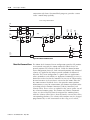
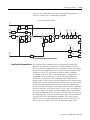
Servo Loop Block Diagrams . . . . . . . . . .
Motor Position Servo . . . . . . . . . . . . . . .
Auxiliary Position Servo . . . . . . . . . . . . .
Dual Feedback Servo . . . . . . . . . . . . . . .
Motor Dual Command Servo . . . . . . . . .
Auxiliary Dual Command Servo . . . . . . .
Dual Command Feedback Servo. . . . . . .
Velocity Servo . . . . . . . . . . . . . . . . . . . .
.
.
.
.
.
.
.
.
.
.
.
.
.
.
.
.
.
.
.
.
.
.
.
.
.
.
.
.
.
.
.
.
.
.
.
.
.
.
.
.
.
.
.
.
.
.
.
.
.
.
.
.
.
.
.
.
.
.
.
.
.
.
.
.
.
.
.
.
.
.
.
.
.
.
.
.
.
.
.
.
.
.
.
.
.
.
.
.
.
.
.
.
.
.
.
.
.
.
.
.
.
.
.
.
.
.
.
.
.
.
.
.
.
.
.
.
.
.
.
.
.
.
.
.
.
.
.
.
.
.
.
.
.
.
.
.
.
.
.
.
.
.
.
.
.
.
.
.
.
.
.
.
.
.
.
.
.
.
.
.
.
.
.
.
.
.
.
.
.
.
.
.
.
.
.
.
.
.
.
.
.
.
.
.
.
.
.
.
.
.
.
.
.
.
.
.
.
.
.
.
.
.
.
.
.
.
.
.
.
.
.
.
.
.
.
.
.
.
.
.
.
.
.
.
.
.
.
.
.
.
.
.
.
.
.
.
.
.
.
.
.
.
.
.
.
.
.
.
.
.
.
.
.
.
.
.
.
.
.
.
.
.
.
.
.
.
.
.
.
.
.
.
.
.
.
.
.
.
.
.
.
.
.
.
.
.
.
.
.
.
.
.
.
.
.
.
.
.
.
.
.
.
.
.
.
.
.
.
.
.
.
.
.
.
.
.
.
.
.
.
.
.
.
.
.
.
.
.
.
.
.
.
.
.
.
.
.
.
.
.
.
.
.
.
.
.
.
.
.
.
.
.
.
.
.
.
.
.
.
.
.
.
.
.
.
.
.
.
.
.
.
.
.
.
.
.
.
.
.
.
.
.
.
.
.
.
.
.
.
.
.
.
.
.
.
.
.
.
.
.
.
.
.
.
.
.
.
.
.
.
.
.
.
.
9
13-109
13-110
13-116
13-118
13-119
13-120
13-120
13-120
13-121
13-121
13-121
13-122
13-122
13-122
13-123
13-124
13-124
13-125
13-125
13-125
13-126
13-128
13-128
13-129
13-129
13-131
13-133
13-134
13-135
13-136
13-136
13-136
13-137
13-138
13-138
13-138
13-139
13-140
13-141
13-141
13-142
13-143
13-144
13-145
13-146
13-146
Publication 1756-UM006G-EN-P - May 2005
Table of Contents
10
Torque Servo. . . . . . . . . . . . . . . . . . . . .
Drive Gains . . . . . . . . . . . . . . . . . . . . . .
Position Proportional Gain . . . . . . . . . . .
Position Integral Gain . . . . . . . . . . . . . .
Velocity Feedforward Gain . . . . . . . . . . .
Acceleration Feedforward Gain. . . . . . . .
Velocity Proportional Gain . . . . . . . . . . .
Velocity Integral Gain . . . . . . . . . . . . . .
Output LP Filter Bandwidth . . . . . . . . . .
Output Notch Filter Frequency . . . . . . . .
Torque Scaling. . . . . . . . . . . . . . . . . . . .
Integrator Hold Enable. . . . . . . . . . . . . .
Advanced Drive Gain Attributes . . . . . . .
Drive Limits . . . . . . . . . . . . . . . . . . . . . . . .
Maximum Positive/Negative Travel . . . . .
Position Error Tolerance. . . . . . . . . . . . .
Position Lock Tolerance . . . . . . . . . . . . .
Torque Limit . . . . . . . . . . . . . . . . . . . . .
Continuous Torque Limit . . . . . . . . . . . .
Advanced Drive Limits . . . . . . . . . . . . . .
Drive Offsets. . . . . . . . . . . . . . . . . . . . . . . .
Friction Compensation . . . . . . . . . . . . . .
Friction Compensation Window . . . . . . .
Velocity Offset . . . . . . . . . . . . . . . . . . . .
Torque Offset . . . . . . . . . . . . . . . . . . . .
Backlash Reversal Error . . . . . . . . . . . . .
Backlash Stabilization Window . . . . . . . .
Drive Fault Actions . . . . . . . . . . . . . . . .
Advanced Stop Action Attributes. . . . . . .
Brake Engage Delay. . . . . . . . . . . . . . . .
Brake Release Delay . . . . . . . . . . . . . . .
Resistive Brake Contact Delay . . . . . . . .
Drive Power Attributes . . . . . . . . . . . . . .
Power Supply ID . . . . . . . . . . . . . . . . . .
Bus Regulator ID . . . . . . . . . . . . . . . . . .
PWM Frequency Select. . . . . . . . . . . . . .
Commissioning Configuration Attributes .
Test Increment. . . . . . . . . . . . . . . . . . . .
Tuning Travel Limit . . . . . . . . . . . . . . . .
Tuning Speed . . . . . . . . . . . . . . . . . . . .
Tuning Torque. . . . . . . . . . . . . . . . . . . .
Damping Factor . . . . . . . . . . . . . . . . . . .
Drive Model Time Constant . . . . . . . . . .
Velocity Servo Bandwidth . . . . . . . . . . .
Position Servo Bandwidth . . . . . . . . . . .
Motor Inertia & Load Inertia Ratio. . . . . .
Publication 1756-UM006G-EN-P - May 2005
.
.
.
.
.
.
.
.
.
.
.
.
.
.
.
.
.
.
.
.
.
.
.
.
.
.
.
.
.
.
.
.
.
.
.
.
.
.
.
.
.
.
.
.
.
.
.
.
.
.
.
.
.
.
.
.
.
.
.
.
.
.
.
.
.
.
.
.
.
.
.
.
.
.
.
.
.
.
.
.
.
.
.
.
.
.
.
.
.
.
.
.
.
.
.
.
.
.
.
.
.
.
.
.
.
.
.
.
.
.
.
.
.
.
.
.
.
.
.
.
.
.
.
.
.
.
.
.
.
.
.
.
.
.
.
.
.
.
.
.
.
.
.
.
.
.
.
.
.
.
.
.
.
.
.
.
.
.
.
.
.
.
.
.
.
.
.
.
.
.
.
.
.
.
.
.
.
.
.
.
.
.
.
.
.
.
.
.
.
.
.
.
.
.
.
.
.
.
.
.
.
.
.
.
.
.
.
.
.
.
.
.
.
.
.
.
.
.
.
.
.
.
.
.
.
.
.
.
.
.
.
.
.
.
.
.
.
.
.
.
.
.
.
.
.
.
.
.
.
.
.
.
.
.
.
.
.
.
.
.
.
.
.
.
.
.
.
.
.
.
.
.
.
.
.
.
.
.
.
.
.
.
.
.
.
.
.
.
.
.
.
.
.
.
.
.
.
.
.
.
.
.
.
.
.
.
.
.
.
.
.
.
.
.
.
.
.
.
.
.
.
.
.
.
.
.
.
.
.
.
.
.
.
.
.
.
.
.
.
.
.
.
.
.
.
.
.
.
.
.
.
.
.
.
.
.
.
.
.
.
.
.
.
.
.
.
.
.
.
.
.
.
.
.
.
.
.
.
.
.
.
.
.
.
.
.
.
.
.
.
.
.
.
.
.
.
.
.
.
.
.
.
.
.
.
.
.
.
.
.
.
.
.
.
13-147
13-147
13-147
13-149
13-150
13-151
13-152
13-153
13-154
13-155
13-155
13-156
13-156
13-156
13-156
13-157
13-157
13-158
13-159
13-159
13-160
13-160
13-160
13-161
13-161
13-161
13-162
13-163
13-164
13-165
13-165
13-166
13-167
13-167
13-168
13-168
13-168
13-169
13-169
13-169
13-169
13-170
13-170
13-171
13-171
13-172
Table of Contents
Tuning Configuration Bits . . . . . . . . . . . . . . . . . . .
Motion Coordinate System Object . . . . . . . . . . . . . . . .
Introduction. . . . . . . . . . . . . . . . . . . . . . . . . . . . . .
Group, Axis and Coordinate System Relationships . .
Motion Coordinate System Object Status Attributes . . . .
Motion Group Instance . . . . . . . . . . . . . . . . . . . . .
Coordinate System Status . . . . . . . . . . . . . . . . . . . .
Coordinate Motion Status . . . . . . . . . . . . . . . . . . . .
Axis Fault . . . . . . . . . . . . . . . . . . . . . . . . . . . . . . .
Faulted / Shutdown / Servo On Axes . . . . . . . . . . .
Actual Position. . . . . . . . . . . . . . . . . . . . . . . . . . . .
Address of . . . . . . . . . . . . . . . . . . . . . . . . . . . . . . .
Motion Coordinate System Configuration Attributes . . .
Coordinate System General Configuration Attributes
System Type . . . . . . . . . . . . . . . . . . . . . . . . . . . . .
Dimension. . . . . . . . . . . . . . . . . . . . . . . . . . . . . . .
Axes . . . . . . . . . . . . . . . . . . . . . . . . . . . . . . . . . . .
Max Pending Moves. . . . . . . . . . . . . . . . . . . . . . . .
Coordination Mode . . . . . . . . . . . . . . . . . . . . . . . .
Coordinate System Auto Tag Update. . . . . . . . . . . .
Coordinate System Units Configuration . . . . . . . . . . . .
Coordination Units. . . . . . . . . . . . . . . . . . . . . . . . .
Conversion Ratio . . . . . . . . . . . . . . . . . . . . . . . . . .
Coordinate System Dynamics Configuration . . . . . . . . .
Maximum Speed . . . . . . . . . . . . . . . . . . . . . . . . . .
Maximum Acceleration. . . . . . . . . . . . . . . . . . . . . .
Maximum Deceleration . . . . . . . . . . . . . . . . . . . . .
Actual Position Tolerance . . . . . . . . . . . . . . . . . . . .
Command Position Tolerance. . . . . . . . . . . . . . . . .
.
.
.
.
.
.
.
.
.
.
.
.
.
.
.
.
.
.
.
.
.
.
.
.
.
.
.
.
.
11
13-173
13-174
13-174
13-175
13-176
13-176
13-177
13-178
13-179
13-180
13-181
13-181
13-181
13-182
13-182
13-182
13-182
13-182
13-183
13-183
13-183
13-183
13-184
13-184
13-184
13-184
13-184
13-185
13-185
Chapter 14
Troubleshoot Module Lights
1756-M02AE LED Indicators. . . . . . . . . . . . . . . . . . . . . . . . 14-1
1756-M02AE Module Status Using the OK Indicator . . . . 14-1
1756-M02AE Module Status Using the FDBK Indicator . . 14-2
1756-M02AE Module Status Using the DRIVE Indicator . 14-3
1756-M02AS LED Indicators . . . . . . . . . . . . . . . . . . . . . . . . 14-4
1756-M02AS Module Status Using the OK Indicator . . . . 14-4
1756-M02AS Module Status Using the FDBK Indicator . . 14-5
1756-M02AS Module Status Using the DRIVE Indicator . 14-6
1756-HYD02 Module LED Indicators . . . . . . . . . . . . . . . . . 14-7
1756-HYD02 Module Status Using the OK Indicator . . . 14-7
1756-HYD02 Module Status Using the FDBK Indicator. . 14-8
1756-HYD02 Module Status Using the DRIVE Indicator . 14-9
SERCOS interface LED Indicators . . . . . . . . . . . . . . . . . . . 14-10
1756-M03SE, -M08SE, & -M16SE SERCOS Communication
Phase Status Using the CP Indicator . . . . . . . . . . . . . . 14-11
Publication 1756-UM006G-EN-P - May 2005
Table of Contents
12
1756-M03SE, -M08SE, & -M16SE Module Status Using the OK
Indicator . . . . . . . . . . . . . . . . . . . . . . . . . . . . . . . . . . 14-11
1756-M03SE, -M08SE, & -M16SE SERCOS Ring Status . . 14-12
Chapter 15
Troubleshoot Axis Motion
About this chapter. . . . . . . . . . . . . . . . . . . . . . . . . . . . . . . 15-1
Why does my axis accelerate when I stop it? . . . . . . . . . . . 15-1
Example . . . . . . . . . . . . . . . . . . . . . . . . . . . . . . . . . . . 15-1
Look for . . . . . . . . . . . . . . . . . . . . . . . . . . . . . . . . . . . 15-1
Cause . . . . . . . . . . . . . . . . . . . . . . . . . . . . . . . . . . . . . 15-2
Corrective action . . . . . . . . . . . . . . . . . . . . . . . . . . . . . 15-2
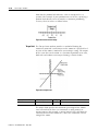
Why does my axis overshoot its target speed? . . . . . . . . . . 15-3
Example . . . . . . . . . . . . . . . . . . . . . . . . . . . . . . . . . . . 15-3
Look for . . . . . . . . . . . . . . . . . . . . . . . . . . . . . . . . . . . 15-3
Cause . . . . . . . . . . . . . . . . . . . . . . . . . . . . . . . . . . . . . 15-4
Corrective action . . . . . . . . . . . . . . . . . . . . . . . . . . . . . 15-5
Why is there a delay when I stop and then restart a jog?. . . 15-6
Example . . . . . . . . . . . . . . . . . . . . . . . . . . . . . . . . . . . 15-6
Look for . . . . . . . . . . . . . . . . . . . . . . . . . . . . . . . . . . . 15-6
Cause . . . . . . . . . . . . . . . . . . . . . . . . . . . . . . . . . . . . . 15-7
Corrective action . . . . . . . . . . . . . . . . . . . . . . . . . . . . . 15-7
Why does my axis reverse direction when I stop and start it? . .
15-8
Example . . . . . . . . . . . . . . . . . . . . . . . . . . . . . . . . . . . 15-8
Look for . . . . . . . . . . . . . . . . . . . . . . . . . . . . . . . . . . . 15-8
Cause . . . . . . . . . . . . . . . . . . . . . . . . . . . . . . . . . . . . . 15-9
Corrective action . . . . . . . . . . . . . . . . . . . . . . . . . . . . 15-10
Chapter 16
Inhibit an Axis
Purpose . . . . . . . . . . . . . . .
When . . . . . . . . . . . . . . . . .
Example 1 . . . . . . . . . . .
Example 2 . . . . . . . . . . .
Before You Begin . . . . . . . .
Example: Inhibit an Axis . . .
Example: Uninhibit an Axis .
.
.
.
.
.
.
.
.
.
.
.
.
.
.
.
.
.
.
.
.
.
.
.
.
.
.
.
.
.
.
.
.
.
.
.
.
.
.
.
.
.
.
.
.
.
.
.
.
.
.
.
.
.
.
.
.
.
.
.
.
.
.
.
.
.
.
.
.
.
.
.
.
.
.
.
.
.
.
.
.
.
.
.
.
.
.
.
.
.
.
.
.
.
.
.
.
.
.
.
.
.
.
.
.
.
.
.
.
.
.
.
.
.
.
.
.
.
.
.
.
.
.
.
.
.
.
.
.
.
.
.
.
.
.
.
.
.
.
.
.
.
.
.
.
.
.
.
.
.
.
.
.
.
.
.
.
.
.
.
.
.
16-1
16-1
16-1
16-1
16-2
16-5
16-6
.......
.......
.......
Module .
.
.
.
.
A-1
A-3
A-6
A-9
Appendix A
Specifications and Performance
Publication 1756-UM006G-EN-P - May 2005
1756-M02AE Motion Module . . . . . . . . . . . . . . .
1756-HYD02 Motion Module . . . . . . . . . . . . . . .
1756-M02AS Motion Module . . . . . . . . . . . . . . .
1756-M03SE, 1756-M08SE, & 1756-M16SE Motion
Table of Contents
13
Appendix B
Loop and Interconnect Diagrams
Understanding Block Diagrams . . . . . . . . . . . . . . . . . . . . . B-1
Using a 1756-M02AE Module With a Torque Servo Drive B-2
Using a 1756-M02AE Module With a Velocity Servo Drive .
B-3
Understanding Wiring Diagrams . . . . . . . . . . . . . . . . . . . . B-4
Wiring to a Servo Module RTB . . . . . . . . . . . . . . . . . . . B-4
Wiring to an Ultra 100 Series Drive . . . . . . . . . . . . . . . . B-5
Wiring to an Ultra 200 Series Drive . . . . . . . . . . . . . . . . B-6
1398-CFLAExx Cable Diagram . . . . . . . . . . . . . . . . . . . B-6
Pinouts for 1398-CFLAExx Cable. . . . . . . . . . . . . . . . . . B-7
Wiring the Ultra3000 Drive . . . . . . . . . . . . . . . . . . . . . . B-7
Wiring to a 1394 Servo Drive (in Torque Mode only) . . B-9
The 1394-CFLAExx Cable Wiring Diagram. . . . . . . . . . B-10
Pinouts for the 1394-CFLAE . . . . . . . . . . . . . . . . . . . . B-10
Wiring Registration Sensors . . . . . . . . . . . . . . . . . . . . B-10
Wiring the Home Limit Switch Input. . . . . . . . . . . . . . B-12
Wiring the OK Contacts . . . . . . . . . . . . . . . . . . . . . . . B-12
Publication 1756-UM006G-EN-P - May 2005
Table of Contents
14
Publication 1756-UM006G-EN-P - May 2005
Chapter
1
The ControlLogix Motion Control System
This chapter describes the ControlLogix motion control system.
ControlLogix Motion
Control
The ControlLogix controller, 1756-M02AE servo module, 1756-M03SE,
1756-M08SE, and 1756-M16SE SERCOS interface modules, and RSLogix
5000 programming software provide integrated motion control
support.
• The ControlLogix controller contains a high-speed motion task,
which executes ladder motion commands and generates
position and velocity profile information. The controller sends
this profile information to one or more 1756-M02AE servo
modules or 1756-MxxSE SERCOS interface modules. You can use
several Logix controllers in each chassis. Each controller can
control up to 32 axes of motion.
• The 1756-L60M03SE is a combination of two existing modules,
physically connected together to form a double wide
ControlLogix module. It is comprised of the 1756-L63 controller
and a 1756-M03SE motion module. This product is targeted to
users that have a 3 axis or less SERCOS interface application.
• The 1756-M02AE servo module connects to a servo drive and
closes a high-speed position and velocity loop. Each Logix
controller can support up to 16 1756-M02AE servo modules.
Each 1756-M02AE module can control up to two axes.
• The 1756-HYD02 is modeled along the lines of the 1756-M02AE
with emphasis on hydraulic applications. It supports two axes
and the AXIS_SERVO data type.
• The 1756-M02AS is a two channel Synchronous Serial Interface
(SSI) module that implements a complete two axis digital
position servo system using absolute transducers with SSI
feedback.
• The 1756-M03SE SERCOS interface module serves as the
interface between one ControlLogix processor and 1 to 3 axes
operating in either position or velocity mode. The module has a
programmable ring Cycle Period of 0.5 ms, 1 ms, or 2 ms
depending on the number of axes and a ring Data Rate of 4 or 8
Mbaud.
1
Publication 1756-UM006G-EN-P - May 2005
1-2
The ControlLogix Motion Control System
• The 1756-M08SE SERCOS interface module serves as the
interface between one ControlLogix processor and 1 to 8 axes
operating in either position or velocity mode. The module has a
programmable ring Cycle Period of 0.5 ms, 1 ms, or 2 ms
depending on the number of axes and a ring Data Rate of 4 or 8
Mbaud.
• The 1756-M16SE SERCOS interface module serves as the
interface between one ControlLogix processor and 1 to 16 axes
operating in either position or velocity mode. The module has a
programmable ring Cycle Period of 0.5 ms, 1 ms, or 2 ms
depending on the number of axes and a ring Data Rate of 4 or 8
Mbaud.
• RSLogix 5000 programming software provides complete axis
configuration and motion programming support.
Figure 1.1 ControlLogix System with 1756-M02AE
Publication 1756-UM006G-EN-P - May 2005
The ControlLogix Motion Control System
1-3
Figure 1.2 ControlLogix System with 1756-MxxSE
Components of the
ControlLogix Motion
System
The ControlLogix Controller The ControlLogix controller is the main component in the
ControlLogix system. It supports sequential and motion functions, and
it performs all of the motion command execution and motion
trajectory planner functions. You can use one or more ControlLogix
controllers in each chassis, and each controller can control up to 32
axes of motion.
The ControlLogix controller provides the following motion support:
• Thirty eight motion instructions
• A high-speed motion task, which manages motion functions and
generates move profiles
• The ability to control up to 16 Analog/Encoder servo modules
for a total of 32 axes
• SERCOS support
The Combo Module (1756-L60M03SE) The Combo module is comprised of the 1756-L63A controller and the
1756-M03SE SERCOS interface motion module. The two modules are
physically connected to each other to form a double wide
ControlLogix module with two lenses and one door.
The hardware has the same properties as its two inclusive modules
with these exceptions:
• User RAM is limited to 750Kbytes.
• It has 8Mbytes of Flash memory.
The Analog/Encoder Servo Module The Analog/Encoder servo module provides an analog/quadrature
(1756-MO2AE) encoder servo drive interface. The servo module receives
configuration and move information from the ControlLogix controller
and manages motor position and velocity.
The servo module supports:
Publication 1756-UM006G-EN-P - May 2005
1-4
The ControlLogix Motion Control System
•
•
•
•
•
•
•
•
Connection capability for up to two drives
±10V analog outputs
Quadrature encoder inputs
Home limit switch inputs
Drive fault inputs
Drive enable outputs
5V or 24V position registration inputs
250 µs position and velocity loop updates
The Hydraulic Module (1756-HYD02) The Hydraulic Module implements a complete two axis digital
position servo system using Linear Magnetostrictive Displacement
Transducer (LDT) inputs providing analog servo output to external
and proportional valves.
The Hydraulic module supports many of the same features as the
1756-M02AE with these exceptions:
• Feed Forward adjust is supported in addition to single-step
Auto Tune.
• Gain ratio between extend direction and retract direction to
accommodate hydraulic cylinder dynamics.
• Intelligent transducer noise detection filtering in hardware and
firmware replaces programmable IIR filtering.
• No encoder feedback.
• LDT interface consisting of Differential Interrogate and Return
signals replaces the differential encoder interface.
• Position feedback update rate is variable (0.5, 1, and 2
milliseconds).
• A dead-band eliminator algorithm compensates for proportional
valves with overlap.
The Synchronous Serial Interface The ControlLogix SSI module implements a complete two axis digital
(SSI) Module (1756-M02AS) position servo system using absolute transducers with Synchronous
Serial Interface (SSI) feedback.
The SSI module supports many of the same features as the
1756-M02AE with these exceptions:
• Feed Forward adjust is supported in addition to single-step
Auto Tune.
• Gain ratio between extend direction and retract direction to
accommodate hydraulic cylinder dynamics.
• Intelligent transducer noise detection filtering in hardware and
firmware replaces programmable IIR filtering.
Publication 1756-UM006G-EN-P - May 2005
The ControlLogix Motion Control System
1-5
• No encoder feedback.
• SSI interface consisting of Differential Clock output and Data
return signals replaces the differential encoder interface.
• Position feedback update rate is variable (0.2, 0.5, 1, and 2
milliseconds).
• A dead-band eliminator algorithm compensates for proportional
valves with overlap.
The 3, 8, or 16 Axis SERCOS interface The 3, 8, or 16 Axis SERCOS interface modules (1756-M03SE,
Module (1756-M08SE, 1756-M16SE) 1756-M08SE, 1756-M16SE) serves as a link between the ControlLogix
platform and intelligent drives. The communication link between the
module and the drive(s) is via IEC 1491 SErial Real-time
COmmunication System (SERCOS) using fiber optic medium.
The SERCOS interface module supports:
•
•
•
•
reliable high speed data transmission
excellent noise immunity
elimination of interconnect wiring
ASA messages converted to SERCOS formatted messages
RSLogix 5000 Programming Software The RSLogix 5000 programming software provides complete
programming and commissioning support for the ControlLogix
system. RSLogix 5000 is the only programming software needed to
fully configure and program ControlLogix motion control systems.
RSLogix 5000 software provides the following motion support:
• Wizards for servo axis configuration including drive hookup
diagnostics and auto tuning
• Ladder-based application programming including support for 31
motion commands
Developing a Motion
Control Application
Program
This section provides an introduction to concepts used in developing
application programs for motion control. These concepts include:
•
•
•
•
•
Application program development
The MOTION_INSTRUCTION tag
Motion status and configuration parameters
Modifying motion configuration parameters
Handling motion faults
Publication 1756-UM006G-EN-P - May 2005
1-6
The ControlLogix Motion Control System
Application Program Development Developing a motion control application program involves the
following:
Task
Description
Select the master coordinated system
time
Sets one controller as the master
controller. Once you complete this
step, you can synchronize all the
motion modules and ControlLogix
controllers in your chassis
Name and Configure an axis
Adds an axis to your application
program
Develop a motion application program
Create a program for your motion
control application
Add a motion module
Adds a motion module to your
application program
Assign additional servo modules and
axes
Adds additional modules and axes to
your application program
Run hookup diagnostics and auto
tuning
Completes hookup diagnostics and
auto tuning for each axis
The MOTION_INSTRUCTION Tag The controller uses the MOTION_INSTRUCTION tag (structure) to
store status information during the execution of motion instructions.
Every motion instruction has a motion control parameter that requires
a MOTION_INSTRUCTION tag to store status information.
The
motion control
parameter
Figure 1.3 Motion Control Parameter
ATTENTION
Tags used for the motion control parameter of
instructions should only be used once. Re-use of the
motion control parameter in other instructions can
cause unintended operation of the control variables.
For more information about the MOTION_INSTRUCTION tag, refer to
Appendix C - The Motion Control Structures and the Logix Controller
Motion Instruction Set Reference Manual (1756-RM007).
Publication 1756-UM006G-EN-P - May 2005
The ControlLogix Motion Control System
1-7
Motion Status and Configuration You can read motion status and configuration parameters in your
Parameters ladder logic program using two methods.
Method
Example
For more information
Directly accessing
the AXIS and
MOTION_GROUP
structures
• Axis faults
• Motion status
• Servo status
Refer to Appendix C - The
Motion Control Structures
Using the GSV
instruction
• Actual
position
• Command
position
• Actual
velocity
Refer to the Input/Output
Instructions chapter of the
Logix Controller Instruction Set
Reference Manual, publication
1756-RM003B
Modifying Motion Configuration In your ladder logic program, you can modify motion configuration
Parameters parameters using the SSV instruction. For example, you can change
position loop gain, velocity loop gain, and current limits within your
program.
For more information about the SSV instruction, refer to the Logix
Controller Instruction Set Reference Manual, publication 1756-RM003.
Handling Motion Faults Two types of motion faults exist.
Type
Description
Example
Motion
Instruction
Errors
• Do not impact controller
operation
• Should be corrected to
optimize execution time and
ensure program accuracy
A Motion Axis Move
(MAM) instruction with a
parameter out of range
Minor/Maj
or Faults
• Caused by a problem with
the servo loop
• Can shutdown the controller
if you do not correct the fault
condition
The application exceeded
the PositionErrorTolerance
value
For more information about handling faults, see Handling Controller
Faults in the Logix Controller User Manual, publication 1756-UM001
and Appendix F Fault Handling in this manual.
Publication 1756-UM006G-EN-P - May 2005
1-8
The ControlLogix Motion Control System
Publication 1756-UM006G-EN-P - May 2005
Chapter
2
Quick Start
Use This Chapter
Use this chapter as an overview of how to set up and program motion
control. If you aren’t using SERCOS interface drives and modules, skip
actions 3 and 4.
Action
1
See page
1. Make the Controller the CST Master
2-2
2. Add the Motion Modules
2-3
3. Add SERCOS interface Drives
2-4
4. Set Up Each SERCOS Interface Module
2-5
5. Add the Motion Group
2-6
6. Add Your Axes
2-8
7. Set Up Each Axis
2-9
8. Check the Wiring of Each Drive
2-12
9. Tune Each Axis
2-13
10. Program Motion Control
2-14
11. Additional Actions
2-16
Publication 1756-UM006G-EN-P - May 2005
2-2
Quick Start
Make the Controller the
CST Master
coordinated system time
(CST) master
You must make one module in the chassis the master clock for motion
control. This module is called the coordinated system time (CST)
master.
The master clock for motion control for a chassis. The motion modules set their clocks to
the master.
In most cases, make the controller the CST master.
1.
2.
3.
4.
If you have more than 1 controller in the chassis
If you have more than 1 controller in the chassis, choose 1 of the
controllers to be the CST master. You can’t have more than one CST
master for the chassis.
Publication 1756-UM006G-EN-P - May 2005
Quick Start
Add the Motion Modules
IMPORTANT
2-3
Use up to 16 motion modules with your ControlLogix controller:
For your motion modules, use the firmware revision that goes with
the firmware revision of your controller. See the release notes for your
controller’s firmware.
SERCOS interface?
Use this motion module
Yes
3 axes
1756-M03SE
3 axes plus controller
1756-L60M03SE
8 axes
1756-M08SE
16 axes
1756-M16SE
quadrature feedback
1756-M02AE
LDT feedback
1756-HYD02
SSI feedback
1756-M02AS
No
1.
2.
3.
4.
5.
6.
7.
Publication 1756-UM006G-EN-P - May 2005
2-4
Quick Start
Add SERCOS interface
Drives
See:
• Motion Analyzer, PST-SG003
•
ControlLogix Selection Guide,
1756-SG001
Choose from these SERCOS interface drives:
•
•
•
•
1394
Kinetix 6000
Ultra3000
8720MC
Add SERCOS interface drives to the I/O configuration of the controller.
This lets you use RSLogix 5000 software to set up the drives.
1.
2.
3.
4.
5.
6. Node number of the drive on the SERCOS ring
7.
Publication 1756-UM006G-EN-P - May 2005
Quick Start
Set Up Each SERCOS
Interface Module
2-5
Set the data rate and cycle time for each SERCOS interface module in
your project.
Action
Details
1. Decide which data rate to use.
Do your drives have a 8 Mb data rate (most do)?
• YES — Use a 8 MB data rate.
• NO — Use a 4 MB data rate.
2. Decide which cycle time to use. Use the following table to decide the cycle time for your SERCOS interface module:
Data rate
Number of drives Type of drives
on the ring
Cycle time
4 Mb
1 or 2
Kinetix 6000
0.5 ms
NOT Kinetix 6000
1 ms
8 Mb
3 or 4
1 ms
5…8
2 ms
9…16
Can’t do. You must have 2 motion modules.
1…4
Kinetix 6000
0.5 ms
NOT Kinetix 6000
1 ms
5…8
1 ms
9…16
2 ms
3. Set the data rate and cycle time.
A.
B.
C.
D.
Publication 1756-UM006G-EN-P - May 2005
2-6
Quick Start
Add the Motion Group
Add a motion group to set up the motion planner.
motion planner
Part of the controller that takes care of position and velocity information for your axes
coarse update period
How often the motion planner runs. When the motion planner runs, it interrupts all other
tasks regardless of their priority.
motion planner
scans of your code,
system overhead, etc....
0 ms
10 ms
20 ms
30 ms
40 ms
In this example, the coarse update period = 10 ms. Every 10 ms the controller stops scanning your code
and whatever else it is doing and runs the motion planner.
IMPORTANT
Action
1. Choose your coarse update
period.
Add only 1 motion group for the project. RSLogix 5000 software
doesn’t let you add more than 1 motion group.
Details
The coarse update period is a trade-off between updating positions of your axes and
scanning your code. Use these guidelines as a rough starting point.
A. How many axes do you have?
• Less than 11 axes — Set the coarse update period to 10 ms.
• 11 axes or more — Set the coarse update period to 1 ms per axis.
B. Leave at least half the controller’s time for the scan of all your code.
C. If you have SERCOS interface motion modules, set the coarse update period to a
multiple of the cycle time of the motion module.
Example: if the cycle time is 2 ms, set the coarse update period to 8 ms, 10 ms,
12 ms, etc.
D. If you have analog motion modules, set the coarse update period to:
1. At least 3 times the servo update period of the motion module
2. A multiple of the servo update period of the motion module
Publication 1756-UM006G-EN-P - May 2005
Quick Start
Action
2-7
Details
2. Add the motion group.
A.
B.
C.
D.
3. Set the coarse update period.
A.
B.
C.
Publication 1756-UM006G-EN-P - May 2005
2-8
Quick Start
Add Your Axes
Action
Add an axis for each of your drives.
Details
1. Decide which data type to use.
If you use this motion module for the axis
Then use this data type
1756-M03SE
1756-M08SE
1756-M16SE
1756-L60M03SE
AXIS_SERVO_DRIVE
1756-M02AE
1756-HYD02
1756-M02AS
AXIS_SERVO
2. Add an axis.
analog
SERCOS interface
A.
no hardware
B.
C.
D.
Publication 1756-UM006G-EN-P - May 2005
Quick Start
Set Up Each Axis
Action
2-9
The following steps show how to set up the axis of a SERCOS
interface drive. The steps are slightly different if you have a different
type of drive.
Details
1. Open the properties for the axis.
2. Select the drive for the axis.
Select the name that you gave to the drive for this
axis.
3. Set the units that you want to
program in.
A.
B. Type the units that you want to use for
programming, such as revs, degrees,
inches, or millimeters.
Publication 1756-UM006G-EN-P - May 2005
2-10
Quick Start
Action
Details
4. Select the drive and motor
catalog numbers.
A.
B. Select the catalog number of the drive.
C. Select the catalog number of the motor.
5. Set the conversion between
drive counts and units.
A.
B. Select whether this is a rotary or
linear axis.
C. Type the number of drive counts
that equal one unit from Step 3B.
D. If this is a rotary axis, type the
number of drive counts that you
want to unwind after.
6. Set up the homing sequence.
A.
B. Select the type of homing sequence that
you want.
C. Type homing speeds.
Publication 1756-UM006G-EN-P - May 2005
Quick Start
Action
2-11
Details
7. Apply your changes.
A.
B.
Publication 1756-UM006G-EN-P - May 2005
2-12
Quick Start
Check the Wiring of Each
Drive
ATTENTION
Use the hookup tests to check the wiring of a drive.
This test
Does this
Notes
Test marker
Checks that the drive gets the marker
pulse.
You must manually move the
axis for this test.
Test feedback
Checks the polarity of the feedback.
You must manually move the
axis for this test.
Test command
and feedback
Checks the polarity of the drive.
These tests make the axis move even with the controller in remote
program mode.
• Before you do the tests, make sure no one is in the way of the
axis.
• Do not change the polarity after you do the tests. Otherwise you
may cause an axis-runaway condition.
!
1.
controller
download
2.
3.
4.
5.
6. Type how far you want the axis to move
during the tests.
7.
8.
9.
Publication 1756-UM006G-EN-P - May 2005
RUN REM PROG
drive
Quick Start
2-13
Use the Tune tab to tune an axis.
Tune Each Axis
ATTENTION
When you tune an axis, it moves even with the controller in remote
program mode. In that mode, your code is not in control of the axis.
Before you tune an axis, make sure no one is in the way of the axis.
!
The default tuning procedure tunes the proportional gains. Typically,
tune the proportional gains first and see how your equipment runs.
1.
controller
download
2.
3.
RUN REM PROG
drive
4.
5.
6. Type the limit of movement for the axis
during the tuning procedure.
7. Type the maximum speed for your
equipment.
8.
Publication 1756-UM006G-EN-P - May 2005
2-14
Quick Start
Program Motion Control
See:
• Logix5000 Controllers Common
•
•
Procedures Manual, 1756-PM001
Logix5000 Controllers Motion
Instructions Reference Manual,
1756-RM007
Logix5000 Controllers General
Instructions Reference Manual,
1756-RM003
The controller gives you a set of motion control instructions for your
axes.
• Uses these instructions just like the rest of the Logix5000
instructions. You can program motion control in these
programming languages:
– ladder diagram (LD)
– structured text (ST)
– sequential function chart (SFC)
• Each motion instruction works on one or more axes.
• Each motion instruction needs a motion control tag. The tag
uses a MOTION_INSTRUCTION data type. The tag stores the
status information of the instruction.
Motion control tag
ATTENTION
!
Use the tag for the motion control operand of motion instruction
only once. Unintended operation of the control variables may
happen if you re-use of the same motion control tag in other
instructions.
Example
Here’s an example of a simple ladder diagram that homes, jogs, and
moves an axis.
If Initialize_Pushbutton = on and the axis = off (My_Axis_X.ServoActionStatus = off) then
The MSO instruction turns on the axis.
If Home_Pushbutton = on and the axis hasn’t been homed (My_Axis_X.AxisHomedStatus = off) then
The MAH instruction homes the axis.
Publication 1756-UM006G-EN-P - May 2005
Quick Start
2-15
If Jog_Pushbutton = on and the axis = on (My_Axis_X.ServoActionStatus = on) then
The MAJ instruction jogs the axis forward at 8 units/s.
If Jog_Pushbutton = off then
The MAS instruction stops the axis at 100 units/s2
Make sure that Change Decel is Yes. Otherwise, the axis decelerates at its maximum speed.
If Move_Command = on and the axis = on (My_Axis_X.ServoActionStatus = on) then
The MAM instruction moves the axis. The axis moves to the position of 10 units at 1 unit/s.
Publication 1756-UM006G-EN-P - May 2005
2-16
Quick Start
Additional Actions
The following actions are optional and depend on your situation.
Action
Details
Set up a coordinate system
A coordinate system lets you interpolate circular or linear moves using coordinate points.
Set up the coordinate in either 1, 2, or 3 dimensions.
Get status information
Use these methods to read motion status and configuration parameters in your code.
Method:
Example:
• Axis faults
• Actual position of an axis
• Motion status
Read the MOTION_GROUP and AXIS tags
Use a Get System Value (GSV) instruction
Actual position
Change configuration parameters
Use a Set System Value (SSV) instruction to write code that changes motion parameters.
For example, you can change position loop gain, velocity loop gain, and current limits
within your code.
Handle motion faults
The controller has these types of motion faults:
Type
Description
Example
Instruction error
Caused by a motion instruction:
• Instruction errors do not impact controller operation.
• Look at the error code in the motion control tag to see
why an instruction has an error.
• Fix instruction errors to optimize execution time and
make sure that your code is accurate
A Motion Axis Move (MAM)
instruction with a parameter out of
range
Fault
Caused by a problem with the servo loop:
• You choose whether or not motion faults give the
controller major faults.
• Can shutdown the controller if you do not correct the
fault condition
Publication 1756-UM006G-EN-P - May 2005
• Loss of feedback
• Actual position exceeding an
overtravel limit
Chapter
3
Adding and Configuring Your 1756-M02AE,
1756-M02AS, 1756-HYD02 Motion Module
This chapter describes how to add, configure, and edit your
1756-M02AE, 1756-M02AS, and 1756-HYD02 motion modules for use
in your motion control application. Many of the steps are identical
regardless of the module you are adding to the control system.
Adding the 1756-M02AE,
1756-HYD02, or 1756-M02AS
Module
To use your motion module in a control system, you must add your
motion module to the application program. To add a motion module:
1. Right-click the I/O Configuration folder.
Figure 3.1 Selecting New Module from the Controller Organizer
1
Publication 1756-UM006G-EN-P - May 2005
3-2
Adding and Configuring Your 1756-M02AE, 1756-M02AS, 1756-HYD02 Motion Module
2. Select New Module. The Select Module Type window appears.
Figure 3.2 Select Module Type Screen Fully Loaded
Publication 1756-UM006G-EN-P - May 2005
Adding and Configuring Your 1756-M02AE, 1756-M02AS, 1756-HYD02 Motion Module
3-3
3. Click on the Clear All button to clear the dialog window then
click on Motion to list the available Motion Modules.
Figure 3.3 Select Module Type Screen with Motion Options - M02AE Highlighted
New Module Use this dialog to select and create a new module. The context
sensitive menu appears, from which you can select the module for
your application.
Type
The Type field displays the catalog number of the module highlighted
in the Type list box. You can either type in a module catalog number
in this field to quickly select/find the module you want to create or
you can scroll through the list of modules in the Type list box.
Type (list box)
This box lists the installed module catalog numbers based on the
selected check boxes.
Publication 1756-UM006G-EN-P - May 2005
3-4
Adding and Configuring Your 1756-M02AE, 1756-M02AS, 1756-HYD02 Motion Module
Description (list box)
This portion of the list box contains descriptions of the modules.
Show
Displays check boxes, which support filtering on particular types of
modules.
Check this box:
If you want to:
Digital
display digital modules supported by the software
Analog
display analog modules supported by the software
Communication
display communication modules supported by the software
Motion
display motion modules supported by the software
Controller
display controller modules supported by the software
Vendor
display a particular vendor's module profiles that are installed on the system.
Other
display modules that do not fit under the rest of the check box categories.
Select All
Click on this button to display all modules in the list box; all the check
boxes in the Show field are checked.
Clear All
Click on this button to clear all check boxes in the Show field.
4. In the Type field, select the appropriate motion module. For the
purposes of this chapter select a 1756-HYD02 2 Axis
Hydraulic Servo, 1756-M02AE 2 Axis Analog/Encoder
Servo, or 1756-M02AS 2 Axis Analog/SSI Servo. Whichever
you select, the remaining steps and screens are the same.
Publication 1756-UM006G-EN-P - May 2005
Adding and Configuring Your 1756-M02AE, 1756-M02AS, 1756-HYD02 Motion Module
3-5
5. Select OK. The Module Create Wizard displays.
Figure 3.4 Module Properties Dialog Wizard - Naming the Module
6. Make entries in the following fields.
Field
Entry
Name
Type a name for the servo module.
The name can:
• have a maximum of 40 characters
• contain letters, numbers and underscores (_).
Slot
Enter the number of the chassis slot that contains your
module.
Description
Type a description for your motion module.
This field is optional.
Revision
The major revision portion is already filled in based on
the version of the software that you are running. The
motion modules are lockstepped with the software and
share the major revision number. The minor revision can
be changed to match the minor revision of the module.
Publication 1756-UM006G-EN-P - May 2005
3-6
Adding and Configuring Your 1756-M02AE, 1756-M02AS, 1756-HYD02 Motion Module
Field
Entry
Electronic
keying
Select the electronic keying level.
To
Select
Match the vendor, catalog
number, and major revision
attributes of the physical module
and the software configured
module
Compatible module
Disable the electronic keying
protection mode
Disable keying
Match the vendor, catalog
number, major revision, and
minor revision attributes of the
physical module and the
software configured module
Exact match
7. Press the Next button to proceed to the next Create Wizard
screen.
Figure 3.5 Module Properties Wizard - Fault Handling
Publication 1756-UM006G-EN-P - May 2005
Adding and Configuring Your 1756-M02AE, 1756-M02AS, 1756-HYD02 Motion Module
3-7
8. This screen is where you determine how faults are to be
handled. The choices are to inhibit module or to configure the
module so that a loss of connection to this module causes a
major fault. Make your entries and press the Next button to
proceed to the next wizard screen.
Figure 3.6 Module Properties Wizard - Servo Update/Associated Axis
9. This screen lets you associate an axis with the module. Make the
appropriate choices for your application. At this point, the rest
of the screens are informational only and it would be best to
press the Finish button to create the module.
All of the above screens can be accessed and edited by going to the
tabbed Module Property screens. Further explanations of the fields in
this dialog are detailed below.
Editing Your Motion Module
Settings
The following section provides explanations of the Motion Module
Properties screens. Use these screens to edit the properties of the
module when changes need to be made. You can access the Module
Properties screen by highlighting the motion module and right
clicking the mouse.
Publication 1756-UM006G-EN-P - May 2005
3-8
Adding and Configuring Your 1756-M02AE, 1756-M02AS, 1756-HYD02 Motion Module
Select Properties from the displayed pop-up menu screen as shown
in the following figure.
Figure 3.7 Controller Organizer - Module Properties Pop up
This accesses the Module Properties screen. The screen is tabbed to
expedite movement to the required dialog.
Figure 3.8 Module Properties - General Tab
General Tab Use this tab to create/view module properties for 1756-M02AE motion
module. This dialog provides you with the means to view the type,
description, vendor, and the name of the parent module. You can also
enter the name and a description for the module. Other fields and
buttons on this dialog let you set the slot location of the module,
Publication 1756-UM006G-EN-P - May 2005
Adding and Configuring Your 1756-M02AE, 1756-M02AS, 1756-HYD02 Motion Module
3-9
review information for both channels, go to the New Tag dialog to
create an axis to associate with one of the channels, select the minor
revision number and select an electronic keying option. You can also
view the status the controller has about the module but, only when
online.
Type
Displays the type and description of the module being created (read
only).
Vendor
Displays the vendor of the module being created (read only).
Name
Enter the name of the module.
The name must be IEC 1131-3 compliant. If you attempt to enter an
invalid character or exceed the maximum length, the software beeps
and ignores the character.
Description
Enter a description for the module here, up to 128 characters. You
can use any printable character in this field. If you exceed the
maximum length, the software beeps to warn you, and ignores any
extra characters.
Slot
Enter the slot number where the module resides. The spin button
contains values that range from 0 to 1 less than the chassis size (e.g., if
you have a 4-slot chassis, the spin button will spin from 0 to 3). If you
enter a slot number that is out of this range, you will receive an error
message when you go to apply your changes.
The slot number cannot be changed when online.
Revision
Select the minor revision number of your module.
The revision is divided into the major revision and minor revision. The
major revision displayed cannot be changed as the major revision
number of the module is lockstepped with the major revision of the
software that you have running on your system.
Publication 1756-UM006G-EN-P - May 2005
3-10
Adding and Configuring Your 1756-M02AE, 1756-M02AS, 1756-HYD02 Motion Module
Electronic Keying
Select one of these keying options for your module during initial
module configuration:
• Exact Match - all of the parameters must match or RSLogix
rejects the inserted module.
• Vendor
• Product Type
• Catalog Number
• Major Revision
• Minor Revision
• Compatible Module
• the Module Types, Catalog Number, and Major Revision must
match
• the Minor Revision of the physical module must be equal to
or greater than the one specified in the software or RSLogix
5000 will reject the inserted module.
• Disable Keying - RSLogix 5000 will not employ keying at all.
When you insert a module into a slot in a ControlLogix chassis,
RSLogix 5000 compares the following information for the inserted
module to that of the configured slot:
•
•
•
•
•
Vendor
Product Type
Catalog Number
Major Revision
Minor Revision
This feature prevents the inadvertent insertion of the wrong module in
the wrong slot.
Connection Tab The Connection Tab is used to define controller to module behavior.
This is where you select a requested packet interval, choose to inhibit
Publication 1756-UM006G-EN-P - May 2005
Adding and Configuring Your 1756-M02AE, 1756-M02AS, 1756-HYD02 Motion Module
3-11
the module, configure the controller so loss of the connection to this
module causes a major fault, and view module faults.
Figure 3.9 Module Properties - Connection Tab
The data on this tab comes directly from the controller. This tab
displays information about the condition of the connection between
the module and the controller.
Requested Packet Interval
This does not apply to motion modules.
Inhibit Module checkbox
Check/Uncheck this box to inhibit/uninhibit your connection to the
module. Inhibiting the module causes the connection to the module
to be broken.
TIP
Inhibiting/uninhibiting connections applies mainly to
direct connections, and not to the CNB module
ATTENTION
Inhibiting the module causes the connection to the
module to be broken and may result in loss of data
Publication 1756-UM006G-EN-P - May 2005
3-12
Adding and Configuring Your 1756-M02AE, 1756-M02AS, 1756-HYD02 Motion Module
When you check this box and go online, the icon representing this
module in the controller organizer displays the Attention Icon.
If you are:
Check this checkbox to:
offline
put a place holder for a module you are configuring
online
stop communication to a module
If you inhibit the module while you are online and connected to the module, the
connection to the module is nicely closed. The module's outputs go to the last
configured Program mode state.
If you inhibit the module while online but a connection to the module has not
been established (perhaps due to an error condition or fault), the module is
inhibited. The module status information changes to indicate that the module
is 'Inhibited' and not 'Faulted'.
If you uninhibit a module (clear the checkbox) while online, and no fault
condition occurs, a connection is made to the module and the module is
dynamically reconfigured (if you are the owner controller) with the
configuration you have created for that module.
If you are a listener (have chosen a “Listen Only” Communications Format), you
can not re-configure the module.
If you uninhibit a module while online and a fault condition occurs, a
connection is not made to the module.
Major Fault on Controller if Connection Fails checkbox
Check this box to configure the controller so that failure of the
connection to this module causes a major fault on the controller if the
connection for the module fails.
Module Fault
Displays the fault code returned from the controller (related to the
module you are configuring) and the text detailing the Module Fault
that has occurred.
The following are common categories for errors:
• Connection Request Error - The controller is attempting to make
a connection to the module and has received an error . The
connection was not made.
• Service Request Error - The controller is attempting to request a
service from the module and has received an error. The service
was not performed successfully.
• Module Configuration Invalid - The configuration in the module
is invalid. (This error is commonly caused by the Electronic Key
Passed fault ).
Publication 1756-UM006G-EN-P - May 2005
Adding and Configuring Your 1756-M02AE, 1756-M02AS, 1756-HYD02 Motion Module
3-13
• Electronic Keying Mismatch - Electronic Keying is enabled and
some part of the keying information differs between the
software and the module.
Associated Axes Tab This tab lets you assign axis tags to specific channels of the servo
module. Use this tab to configure the selected 1756-M02AE motion
modules by:
• setting the selected 1756-M02AE motion module's Servo Update
Period
• associating axis tags, of the type AXIS_SERVO, with channels 0
and 1
Figure 3.10 Module Properties - Associated Axis Tab
Servo Update Period
Selects the periodic rate at which the 1756-M02AE module closes the
servo loop for the axis, in microseconds (µs).
Channel 0
Represents Channel 0 on the servo module. This field allows you to
associate an AXIS_SERVO tag with channel 0. This field transitions to a
read-only state while online. Associating an existing axis with an
Hydraulic or SSI module may cause changes to the axis configuration.
Click on the button to the right of this field to open the Axis
Properties dialog for the associated axis to make the appropriate
changes to the axis properties. See the chapter entitled Naming and
Publication 1756-UM006G-EN-P - May 2005
3-14
Adding and Configuring Your 1756-M02AE, 1756-M02AS, 1756-HYD02 Motion Module
Configuring Your Motion Axis for more information regarding the
appropriate settings for the type of module you are adding.
Channel 1
Represents Channel 1 on the servo module. This field allows you to
associate an AXIS_SERVO tag with channel 1. This field transitions to a
read-only state while online. Associating an existing axis with an
Hydraulic or SSI module may cause changes to the axis configuration.
Click on the button to the right of this field to open the Axis
Properties dialog for the associated axis to make the appropriate
changes to the axis properties. See the chapter entitled Naming and
Configuring Your Motion Axis for more information regarding the
appropriate settings for the type of module you are adding.
New Axis button
Click on this button to navigate to the New Tag dialog to create an
AXIS_SERVO tag to associate with one of the channels. See the
chapter entitled Naming and Configuring Your Motion Axis in this
manual for more information on creating axes with RSLogix 5000.
Module Info Tab The Module Info tab contains information about the selected module,
however, you can click on:
• Refresh – to display new data from the module.
• Reset Module – to return the module to its power-up state by
emulating the cycling of power. By doing this, you also clear all
faults.
The Module Info Tab displays module and status information about
the module. It also allows you to reset a module to its power-up
state. The information on this tab is not displayed if you are offline or
currently creating a module.
Use this tab to determine the identity of the module.
Publication 1756-UM006G-EN-P - May 2005
Adding and Configuring Your 1756-M02AE, 1756-M02AS, 1756-HYD02 Motion Module
3-15
The data on this tab comes directly from the module. If you selected a
Listen-Only communication format when you created the module, this
tab is not available.
Figure 3.11 Module Properties - Module Info Tab
Identification
Displays the module’s:
•
•
•
•
•
•
Vendor
Product Type
Product Code
Revision Number
Serial Number
Product Name
The name displayed in the Product Name field is read from the
module. This name displays the series of the module. If the module is
a 1756-L1 module, this field displays the catalog number of the
memory expansion board (this selection applies to any controller
catalog number even if additional memory cards are added:
1756-L1M1, 1756-L1M2).
Publication 1756-UM006G-EN-P - May 2005
3-16
Adding and Configuring Your 1756-M02AE, 1756-M02AS, 1756-HYD02 Motion Module
Major/Minor Fault Status
If you are configuring a:
This field displays one of the
following:
digital module
EEPROM fault
Backplane fault
None
analog module
Comm. Lost with owner
Channel fault
None
any other module
None
Unrecoverable
Recoverable
Internal State Status
This field displays the module’s current operational state.
•
•
•
•
•
•
•
•
•
Self-test
Flash update
Communication fault
Unconnected
Flash configuration bad
Major Fault
Run mode
Program mode
(16#xxxx) unknown
If you selected the wrong module from the module selection tab, this
field displays a hexadecimal value. A textual description of this state
is only given when the module identity you provide is a match with
the actual module.
Configured
This field displays a yes or no value indicating whether the module
has been configured by an owner controller connected to it. Once a
module has been configured, it stays configured until the module is
reset or power is cycled, even if the owner drops connection to the
module.
Owned
This field displays a yes or no value indicating whether an owner
controller is currently connected to the module.
Publication 1756-UM006G-EN-P - May 2005
Adding and Configuring Your 1756-M02AE, 1756-M02AS, 1756-HYD02 Motion Module
3-17
Module Identity
Displays:
If the module in the physical slot:
Match
agrees with what is specified on the General Tab. In order for the Match
condition to exist, all of the following must agree:
• Vendor
• Module Type (the combination of Product Type and Product Code for a
particular Vendor)
• Major Revision
Mismatch
does not agree with what is specified on the General Tab
This field does not take into account the Electronic Keying or Minor
Revision selections for the module that were specified on the General
Tab.
Refresh
Click on this button to refresh the tab with new data from the module.
Reset Module
Click on this button to return a module to its power-up state by
emulating the cycling of power.
Resetting a module causes all connections to or through the module to
be closed, and this may result in loss of control.
IMPORTANT
The following modules return an error if a reset is
attempted:1756-L1 ControlLogix5550 Programmable
Controller; 1336T AC Vector Drive; 1395 Digital DC
Drive.
A controller cannot be reset.
Backplane Tab The Backplane tab on the Module Properties window is displayed for
informational purposes. You can use this tab to review diagnostic
information about the module’s communications over the backplane
and the chassis in which it is located, clear a fault, and set the transmit
retry limit.
Information on this tab is displayed only if you are online.
If you selected a Listen-Only communication format when you created
the module , this tab is not available.
Publication 1756-UM006G-EN-P - May 2005
3-18
Adding and Configuring Your 1756-M02AE, 1756-M02AS, 1756-HYD02 Motion Module
The data on this tab comes directly from the module.
Figure 3.12 Module Properties - Backplane Tab
ControlBus Status
This box either displays OK or one of the following errors:
• Receiver disabled
• Multicast addresses disabled
• RA/GA miscompare
To clear the module’s backplane fault, click the Clear Fault button .
ControlBus Parameters
This box contains the following fields and button.
Multicast CRC Error Threshold
This value is the point where it enters a fault state because of Cyclic
Redundancy Check (CRC) errors.
Transmit Retry Limit
Not applicable to motion module.
Publication 1756-UM006G-EN-P - May 2005
Adding and Configuring Your 1756-M02AE, 1756-M02AS, 1756-HYD02 Motion Module
3-19
Set Limit Button
You must click on the Reset Limit button to make the new Transmit
Retry Limit effective. If you do not and then click either the OK or the
Apply button, this limit is not set.
Receive Error Counters
This box displays the number of receiving errors that occurred in the
following categories:
• Bad CRC – errors that occurred on received frames (messages)
• Bus time-out – when the receiver timed out
• CRC error – multicast receive errors
Transmit Error Counters
This box displays the number of transmitting errors that occurred in
the following categories:
• Bad CRC – errors that occurred on transmitted frames
• Bus Time-out – when the transmitter bus timed out
Refresh
Click on the Refresh button to refresh the tab. When you refresh the
tab:
Assigning Additional
Motion Modules
if you’re using:
then:
digital, analog, or motion
modules
counters are cleared
another module
the tab is refreshed but the counters are not
cleared
You can assign additional modules by repeating the preceding
sections. You can assign up to 16 1756-M02AE modules to each
Logix5000 controller. Each module uses a maximum of two axes.
Publication 1756-UM006G-EN-P - May 2005
3-20
Adding and Configuring Your 1756-M02AE, 1756-M02AS, 1756-HYD02 Motion Module
Publication 1756-UM006G-EN-P - May 2005
Chapter
4
Configuring the 1756-M03SE, 1756-M08SE, or
1756-M16SE Module
Adding the 1756-M03SE,
1756-M08SE, or 1756-M16SE
This chapter reviews the necessary steps for configuring the
1756-M03SE, 1756-M08SE, or 1756-M16SE motion module. Much of
this information is the same as for adding and configuring the
1756-M02AE as discussed in the previous chapter.
To configure a 1756-M03SE, 1756-M08SE, or 1756-M16SE motion
module:
1. In the Controller Organizer, right mouse click on I/O
Configuration.
Figure 4.1 Controller Organizer | I/O Configuration| New Module
1
Publication 1756-UM006G-EN-P - May 2005
4-2
Configuring the 1756-M03SE, 1756-M08SE, or 1756-M16SE Module
2. Or in the File menu, select New Component then Module…
Figure 4.2 File Menu | New Component | Module Selected
Publication 1756-UM006G-EN-P - May 2005
Configuring the 1756-M03SE, 1756-M08SE, or 1756-M16SE Module
4-3
3. The Select Module Type screen displays. Select Clear All. Select
Motion. The list displays only available motion modules.
Figure 4.3 Select Module Type Screen with Motion Options - 1756-M03SE Selected
4. Select 1756-M03SE, 1756-M08SE, or 1756-M16SE.
5. Press the OK button to close the Select Module Type dialog.
Publication 1756-UM006G-EN-P - May 2005
4-4
Configuring the 1756-M03SE, 1756-M08SE, or 1756-M16SE Module
6. The Create Module Wizard opens.
Figure 4.4 Module Properties Wizard Dialog - Name the Module
7. Name is the only required field that must be entered to create
the M03SE/M08SE/M16SE module. It must conform to the IEC
1131-3 standard. You can also enter a description for the
module, select the minor revision number of your module, and
select the method for Electronic Keying. Fill in the at least the
required Name field and click the Next> button to advance to
the next wizard screen to enter Connection information or click
on the Finish>> button to create the module. You can then go to
the Module Properties screen to edit any values. (See the section
titled SERCOS interface Motion Module Overview in this chapter for
more information on the fields in these screens.)
Publication 1756-UM006G-EN-P - May 2005
Configuring the 1756-M03SE, 1756-M08SE, or 1756-M16SE Module
4-5
8. The Connection Screen Wizard displays.
Figure 4.5 Module Properties Wizard Dialog - Connection Screen
9. On this screen there are no required fields but you can enter
how you want to handle connection faults. The Requested
Packet Interval (RPI) field does not pertain to the SERCOS
interface modules and is greyed out.
Inhibit Module defaults to Unchecked. Click on the check box to
inhibit the module.
Major Fault on Controller ... check box defaults to uncheck.
Click on the box if you want to check this option. Click on
Next> to advance the SERCOS interface Create Wizard screen.
Publication 1756-UM006G-EN-P - May 2005
4-6
Configuring the 1756-M03SE, 1756-M08SE, or 1756-M16SE Module
10. The SERCOS interface screen displays.
Figure 4.6 Module Properties Wizard Dialog - SERCOS interface Screen
11. On this screen you can enter the Data Rate, SERCOS ring Cycle
time, and the transmit power for the SERCOS ring.
The rest of the Create Wizard screens are only informational and
do not let you enter any information. It saves time if you click
on the Finish>> button at this time.
12. The 1756-M08SE/-M16SE motion module appears in the I/O
Configuration branch of the Controller Organizer. It can now be
put into use or edited as you require.
SERCOS interface Motion
Module Overview
Publication 1756-UM006G-EN-P - May 2005
The 1756-M03SE/-M08SE/-M16SE SERCOS interface motion module
has been added. To edit the 1756-M03SE/-M08SE/-M16SE Module
Properties, go to the I/O Configuration organizer and right click on
Configuring the 1756-M03SE, 1756-M08SE, or 1756-M16SE Module
4-7
the 1756-M03SE/-M08SE/-M16SE module and select Properties from
the drop down menu. The tabbed Module Properties screen displays.
Figure 4.7 Module Properties - General Tab
The Module Properties screen has the following tabs:
• The General tab references the 1756-M03SE/-M08SE/-M16SE
motion module.
• The Connection tab references the connection of the module to
the controller.
• The SERCOS Interface tab is for configuring SERCOS
communication settings for the 1756-M03SE/-M08SE/-M16SE
motion module.
• The SERCOS Interface Info tab is used to monitor the status of
the SERCOS communication ring.
• The Module Info tab, when Online, displays the current
condition of the module.
• The Backplane tab, when Online, displays diagnostic
information about the module’s communication over the
backplane and the chassis in which it is located.
Publication 1756-UM006G-EN-P - May 2005
4-8
Configuring the 1756-M03SE, 1756-M08SE, or 1756-M16SE Module
Editing
1756-M03SE/-M08SE/-M16
SE Module Properties
General Tab Use this tab to create/view module properties for the
1756-M03SE/-M08SE/-M16SE motion module.
On this tab, you can:
•
•
•
•
•
•
•
view the type and description of the module being created
view the vendor of the module being created
enter the name of the module
enter a description for the module
select the slot number of the module on the network
select the minor revision number of your module
select Exact Match, Compatible Module, or Disable Keying
Type
Displays the type and description of the module being created (read
only).
Vendor
Displays the vendor of the module being created (read only).
Name
Enter the name of the module. The name must be IEC 1131-3
compliant. An error message is displayed if you enter an invalid
character or a duplicate name. If you exceed the maximum length, the
software ignores the extra characters.
Description
Enter a description for the module here, up to 128 characters. You can
use any printable character in this field. If you exceed the maximum
length, the software ignores any extra characters.
Slot
Enter the slot number where the module resides. The spin button
contains values that range from 0 to 1 less than the chassis size (e.g., if
you have a 4-slot chassis, the spin button spins from 0 to 3). Only
available slot numbers are listed by the spin button. However, you can
Publication 1756-UM006G-EN-P - May 2005
Configuring the 1756-M03SE, 1756-M08SE, or 1756-M16SE Module
4-9
edit the slot number manually. If you enter a slot number that is out of
this range, you receive an error message when you apply your
changes.
The slot number cannot be changed when online.
Revision
The revision is divided into the major revision and minor revision. The
major revision displayed statically is chosen on the Select Module
Type dialog.
The major revision is used to indicate the revision of the interface to
the module. The minor revision is used to indicate the firmware
revision.
Select the minor revision number of your module.
Electronic Keying
Select one of these keying options for your module during initial
module configuration:
Exact Match - all of the parameters must match or the inserted
module rejects the connection.
Compatible Module - the Module Types, Catalog Number, and Major
Revision must match. The Minor Revision of the physical module must
be equal to or greater than the one specified in the software or the
inserted module rejects the connection.
Disable Keying – Controller does not employ keying at all.
ATTENTION
Changing the Electronic Keying selection may cause
the connection to the module to be broken and may
result in a loss of data.
Be extremely cautious when using this option; if
used incorrectly, this option can lead to personal
injury or death, property damage or economic loss.
Status – This is a Read Only field that displays the Controllers current
opinion of the module.
Standby – A transient state that occurs when shutting down.
Faulted – It is unable to communicate with the module. When
Faulted is displayed, check the Connection Tab fore the fault
listing.
Publication 1756-UM006G-EN-P - May 2005
4-10
Configuring the 1756-M03SE, 1756-M08SE, or 1756-M16SE Module
Validating – A transient state that occurs prior to connecting to
the module.
Connecting – The state while the connection(s) to the module
are established.
Running – The module is communicating and everything is
working as expected.
Shutting Down – The connections are in the process of closing.
Inhibited – The module is prevented from connecting to the
controller.
Waiting – A connection to this module has not been made due
to one of the following reasons.
• Its parent has not yet made a connection to it.
• Its parent is inhibited.
• Its parent is faulted.
Offline – The module is not currently online.
When you insert a module into a slot in a ControlLogix chassis,
RSLogix5000 compares the following information for the inserted
module to that of the configured slot:
•
•
•
•
•
Vendor
Product Type
Catalog Number
Major Revision
Minor Revision
This feature prevents the inadvertent insertion of the wrong module in
the wrong slot.
Connection Tab The Connection Tab reflects controller to module behavior. This is
where you choose to inhibit the module, configure the controller so
Publication 1756-UM006G-EN-P - May 2005
Configuring the 1756-M03SE, 1756-M08SE, or 1756-M16SE Module
4-11
loss of the connection to this module causes a major fault, and view
module faults when online.
Figure 4.8 Module Properties - Connection Tab
The fault data on this tab comes directly from the controller. This tab
displays information about the condition of the connection between
the module and the controller.
Requested Packet Interval
This does not apply to motion modules.
Inhibit Module checkbox
Check/Uncheck this box to inhibit/uninhibit your connection to the
module. Inhibiting the module causes the connection to the module
to be broken. When a module is inhibited all of the associated axes
are not used in the configuration process. The system ignores them as
if they were not there and allows configuration and operation of any
axis associated to other modules in the group.
TIP
Inhibiting/uninhibiting connections applies mainly to
direct connections, and not to the CNB module.
Publication 1756-UM006G-EN-P - May 2005
4-12
Configuring the 1756-M03SE, 1756-M08SE, or 1756-M16SE Module
ATTENTION
Inhibiting the module causes the connection to the
module to be broken and may result in loss of data.
When you check this box and go online, the icon representing this
module in the controller organizer displays the Attention Icon.
If you are:
Check this checkbox to:
offline
put a place holder for a module you are configuring
online
stop communication to a module
If you inhibit the module while you are online and connected to the module, the
connection to the module is nicely closed. The module's outputs go to the last
configured Program mode state.
If you inhibit the module while online but a connection to the module has not
been established (perhaps due to an error condition or fault), the module is
inhibited. The module status information changes to indicate that the module
is 'Inhibited' and not 'Faulted'.
If you uninhibit a module (clear the checkbox) while online, and no fault
condition occurs, a connection is made to the module and the module is
dynamically reconfigured (if you are the owner controller) with the
configuration you have created for that module.
If you are a listener (have chosen a “Listen Only” Communications Format), you
can not re-configure the module.
If you uninhibit a module while online and a fault condition occurs, a
connection is not made to the module.
Major Fault on Controller if Connection Fails checkbox
Check this box to configure the controller so that failure of the
connection to this module causes a major fault on the controller if the
connection for the module fails.
Module Fault
Displays the fault code returned from the controller (related to the
module you are configuring) and the text detailing the Module Fault
that has occurred.
The following are common categories for errors:
• Connection Request Error - The controller is attempting to
make a connection to the module and has received an error. The
connection was not made.
Publication 1756-UM006G-EN-P - May 2005
Configuring the 1756-M03SE, 1756-M08SE, or 1756-M16SE Module
4-13
• Service Request Error - The controller is attempting to request
a service from the module and has received an error. The service
was not performed successfully.
• Module Configuration Invalid - The configuration in the
module is invalid. (This error is commonly caused by the
Electronic Key Passed fault).
• Electronic Keying Mismatch - Electronic Keying is enabled
and some part of the keying information differs between the
software and the module.
SERCOS Interface Tab The SERCOS interface Tab is for configuring the SERCOS ring. It is
here where you set the specific Data Rate, Cycle Time, and Transmit
Power for the named 1756-M03SE/-M08SE/-M16SE SERCOS interface
module.
Figure 4.9 Module Properties - SERCOS Interface Tab
Use the SERCOS Interface Tab to set and display the:
• SERCOS baud rate
• update rate for the SERCOS ring
• fiber optic transmit power range for the SERCOS ring
Publication 1756-UM006G-EN-P - May 2005
4-14
Configuring the 1756-M03SE, 1756-M08SE, or 1756-M16SE Module
The SERCOS ring consists of the drives and axes connected to the
1756-M03SE/-M08SE/-M16SE motion controller.
TIP
The settings on this tab are specific to the
1756-M08SE/-M16SE motion controller.
Data Rate
Select the baud rate for the SERCOS ring. Your options are:
• Auto Detect – automatically scans to detect the SERCOS ring
baud rate as set by the drive(s).
• 4 Mb – sets the SERCOS ring baud rate to 4 Mb. This value must
match the baud rate set on the drives. All drives included in the
ring must be set to 4 Mbaud.
• 8 Mb – sets the SERCOS ring baud rate to 8 Mb.This value must
match the baud rate set on the drives. All drives included in the
ring must be set to 8 Mbaud.
IMPORTANT
If drives are set to both 4 and 8 Mbaud rates and the
motion module’s Data Rate is set to 4 Mbaud, it only
detects the 4Mbaud drives and indicates a closed
ring. Those drives set to 8 Mbaud are ignored. When
the program is run it errs because the drives set to 8
Mbaud are not found.
In the above scenario with the motion module’s Data
Rate set to 8 Mbaud, it errs with "Wrong baud rate".
Cycle Time
This field sets the rate at which drives on the SERCOS ring are
updated. Select the update rate for the SERCOS ring:
• 0.5 ms
NOTE: Many drives to not support an update rate of 0.5 ms.
Check your drive documentation for appropriate values.
• 1 ms
• 2 ms.
Transmit Power
Select the optic transmit power range for the SERCOS ring:
• High
• Low
Publication 1756-UM006G-EN-P - May 2005
Configuring the 1756-M03SE, 1756-M08SE, or 1756-M16SE Module
4-15
It is recommended that you set to High.
SERCOS Interface Info Tab The SERCOS interface Tab is for monitoring the SERCOS ring of the
selected 1756-M08SE/-M16SE while it is on-line. A REFRESH button is
available to access the current values.
Figure 4.10 Module Properties - SERCOS Interface Info Tab
Use this tab to monitor the following:
Ring Comm. Phase
Displays the communications phase of the SERCOS ring:
0: Ring Integrity
1: Polling
2: Identity
3: Configuration
4: Cyclic communication
Fault Type
Displays the current fault type, if any, on the SERCOS ring. Values
include:
Publication 1756-UM006G-EN-P - May 2005
4-16
Configuring the 1756-M03SE, 1756-M08SE, or 1756-M16SE Module
•
•
•
•
•
•
•
•
•
•
•
•
No fault
Loss of received signal
MST error
Missed AT
Excessive AT errors
Duplicate nodes (not currently supported)
No nodes
Wrong ring cycle
Wrong baud rate
Link transport fault
Wrong phase
Wrong AT number
Refresh
Click this button to update this page.
Note: this information does not refresh automatically.
Module Info Tab The Module Info tab contains information about the selected module,
however, you can click on:
• Refresh – to display new data from the module.
• Reset Module – to return the module to its power-up state by
emulating the cycling of power. By doing this, you also clear all
faults.
The Module Info Tab displays module and status information about
the module. It also allows you to reset a module to its power-up
state. The information on this tab is not displayed if you are offline or
currently creating a module.
Use this tab to determine the identity of the module.
Publication 1756-UM006G-EN-P - May 2005
Configuring the 1756-M03SE, 1756-M08SE, or 1756-M16SE Module
4-17
The data on this tab comes directly from the module. If you selected a
Listen-Only communication format when you created the module, this
tab is not available.
Figure 4.11 Module Properties - Module Info Tab
Identification
Displays the module’s:
•
•
•
•
•
•
Vendor
Product Type
Product Code
Revision Number
Serial Number
Product Name
The name displayed in the Product Name field is read from the
module. This name displays the series of the module.
Publication 1756-UM006G-EN-P - May 2005
4-18
Configuring the 1756-M03SE, 1756-M08SE, or 1756-M16SE Module
Major/Minor Fault Status
If you are configuring a:
This field displays one of the
following:
digital module
EEPROM fault
Backplane fault
None
analog module
Comm. Lost with owner
Channel fault
None
any other module
None
Unrecoverable
Recoverable
Internal State Status
This field displays the module’s current operational state.
•
•
•
•
•
•
•
•
•
Self-test
Flash update
Communication fault
Unconnected
Flash configuration bad
Major Fault
Run mode
Program mode
(16#xxxx) unknown
If you selected the wrong module from the module selection tab, this
field displays a hexadecimal value. A textual description of this state is
only given when the module identity you provide is a match with the
actual module.
Configured
This field displays a yes or no value indicating whether the module
has been configured by an owner controller connected to it. Once a
module has been configured, it stays configured until the module is
reset or power is cycled, even if the owner drops connection to the
module.
Owned
This field displays a yes or no value indicating whether an owner
controller is currently connected to the module.
Publication 1756-UM006G-EN-P - May 2005
Configuring the 1756-M03SE, 1756-M08SE, or 1756-M16SE Module
4-19
Module Identity
Displays:
If the module in the physical slot:
Match
agrees with what is specified on the General Tab. In order for the Match
condition to exist, all of the following must agree:
• Vendor
• Module Type (the combination of Product Type and Product Code for a
particular Vendor)
• Major Revision
Mismatch
does not agree with what is specified on the General Tab
This field does not take into account the Electronic Keying or Minor
Revision selections for the module that were specified on the General
Tab.
Refresh
Click on this button to refresh the tab with new data from the module.
Reset Module
Click on this button to return a module to its power-up state by
emulating the cycling of power.
Resetting a module causes all connections to or through the module to
be closed, and this may result in loss of control.
Backplane Tab The Backplane tab on the Module Properties window is displayed for
informational purposes. You can use this tab to review diagnostic
information about the module’s communications over the backplane
and the chassis in which it is located, clear a fault, and set the transmit
retry limit.
Information on this tab is displayed only if you are online.
If you selected a Listen-Only communication format when you created
the module, this tab is not available.
Publication 1756-UM006G-EN-P - May 2005
4-20
Configuring the 1756-M03SE, 1756-M08SE, or 1756-M16SE Module
The data on this tab comes directly from the module.
Figure 4.12 Module Properties - Backplane Tab
ControlBus Status
This box either displays OK or one of the following errors:
• Receiver disabled
• Multicast addresses disabled
• RA/GA miscompare
To clear the module’s backplane fault, click the Clear Fault button.
ControlBus Parameters
This box contains the following fields and button.
Multicast CRC Error Threshold
This value is the point where it enters a fault state because of Cyclic
Redundancy Check (CRC) errors.
Transmit Retry Limit
Not applicable to motion module.
Publication 1756-UM006G-EN-P - May 2005
Configuring the 1756-M03SE, 1756-M08SE, or 1756-M16SE Module
4-21
Set Limit Button
You must click on the Set Limit button to make the new Transmit
Retry Limit effective. If you do not and then click either the OK or the
Apply button, this limit is not set.
Receive Error Counters
This box displays the number of receiving errors that occurred in the
following categories:
• Bad CRC – errors that occurred on received frames (messages)
• Bus time-out – when the receiver timed out
• CRC error – multicast receive errors
Transmit Error Counters
This box displays the number of transmitting errors that occurred in
the following categories:
• Bad CRC – errors that occurred on transmitted frames
• Bus Time-out – when the transmitter bus timed out
Refresh
Click on the Refresh button to refresh the tab. When you refresh the
tab:
if you’re using:
then:
digital, analog, or motion
modules
counters are cleared
another module
the tab is refreshed but the counters are not
cleared
Publication 1756-UM006G-EN-P - May 2005
4-22
Configuring the 1756-M03SE, 1756-M08SE, or 1756-M16SE Module
Publication 1756-UM006G-EN-P - May 2005
Chapter
5
The Motion Group
Creating A Motion Group
Each .acd program must have one motion group. (There can be only
one.) You must create it before an axis can be assigned to the group
and have it function within the .acd program.
To create the motion group, right click on Motion Group and select
New Motion Group from the drop down menu.
Figure 5.1 Controller Organizer - New Motion Group Pop-up
This calls the New Tag window.
Figure 5.2 New Tag Dialog
1. Enter a name for the Motion Group in the Name field.
1
Publication 1756-UM006G-EN-P - May 2005
5-2
The Motion Group
2. In the Description field, enter a description of the tag.
3. Click on the respective radio button to select one of the
following tag types:
• Base - refers to a normal tag (selected by default)
• Alias - refers to a tag, which references another tag with the
same definition. Special parameters appear on the New Tag
dialog that allows you to identify to which base tag the alias
refers.
4. Select MOTION_GROUP for the Data Type.
5. From the Scope pull-down menu, select the scope for the tag.
6. If you want to produce this tag for other controllers to consume,
check the Produce box and enter the maximum number of
consumers.
IMPORTANT
Producing a tag requires a connection for each
consumer. Connections are a limited resource in the
controller, so only produce tags that you know you
are needed in other controllers.
7. Click on the Configure button to proceed through the Motion
Group Wizard screens to set the properties for the motion
group.
If you had clicked on OK instead of the Configure button, it
would have created the group and closed the dialog. You would
then need to access the Motion Group Properties screen to
configure the Motion Group.
Publication 1756-UM006G-EN-P - May 2005
The Motion Group
5-3
The Motion Group Wizard group - Axis Assignment screen displays.
Figure 5.3 Motion Group Wizard Dialog - Axis Assignment
Add any existing axes to the group.
8. Continue on through the Motion Group Wizard to configure
your Motion Group tag as necessary. Click on Finish>> to close
the wizard.
Publication 1756-UM006G-EN-P - May 2005
5-4
The Motion Group
Editing the Motion Group
Properties
The Motion Group properties can be edited by right clicking on the
group name and selecting Motion Group Properties from the drop
down menu.
Figure 5.4 Motion Group Properties Access
Publication 1756-UM006G-EN-P - May 2005
The Motion Group
5-5
The Motion Group Properties tabbed screen displays.
Figure 5.5 Motion Group Properties - Axis Assignment Tag
Axis Assignment Tab The Axis Assignment screen is where axes are either assigned or
unassigned to the Motion Group. When RSLogix 5000 software is
online, all attributes on this dialog transition to a read-only state.
When an attribute transitions to a read-only state, all pending attribute
changes revert back to their offline status.
Unassigned
Lists the axes that are not assigned to any group in the controller.
Assigned
Lists the axes that are assigned to this motion group.
Add
Click on this button to add axes to the motion group.
Publication 1756-UM006G-EN-P - May 2005
5-6
The Motion Group
Remove
Click on this button to remove axes from the motion group.
Attribute Tab The Attribute tab is used to modify the group attributes.
Figure 5.6 Motion Group Properties - Attribute Tag
When RSLogix 5000 software is online, all of the attributes on this tab
transition to a read-only state. When an attribute transitions to a
read-only state, all pending attribute changes are reverted.
Coarse Update Period
Selects the periodic rate at which the motion task executes to compute
the servo commanded position, velocity, and accelerations to be sent
to the 1756-M02AE or 1756-MxxSE modules when executing motion
instructions.
Auto Tag Update
This parameter determines whether or not the axis parameter values
are automatically updated during operation. Choose either:
Publication 1756-UM006G-EN-P - May 2005
The Motion Group
5-7
• Enabled – turns On automatic tag updating
• Disabled – turns Off automatic tag updating
General Fault Type
Selects the general fault type mechanism for the motion group. The
available selections are:
• Non Major Fault – Any faults detected by the motion group will
not cause the processor to fault. The application programmer
needs to handle the fault in the program.
• Major Fault – Any faults detected by the motion group will cause
the processor OK light to go blinking red and the fault routine to
be invoked. If the fault routine handles the fault and clears it,
then the OK light turns green. If the fault routine does not clear
the fault, then the OK light becomes solid red and the processor
stops executing the program.
Scan Times (elapsed time)
• Max – displays the value from the previous scan; clear this
value, if necessary
• Disabled – displays the value from the previous scan
Reset Max
Click on this button to clear the Scan Times Max value.
Publication 1756-UM006G-EN-P - May 2005
5-8
The Motion Group
Tag Tab Use this tab to modify the name and description of the group.
Figure 5.7 Motion Group Properties - Tag Tab
When you are online, all of the parameters on this tab transition to a
read-only state, and cannot be modified. If you go online before you
save your changes, all pending changes revert to their
previously-saved state.
Name
Enter the name of the motion group. This name must not exceed 40
characters. If you enter more than 40 characters, the system notifies
you and it ignores the extra characters.
Description
Enter a description of the motion group. This description must not
exceed 128 characters. If you enter more than 128 characters, the
system notifies you and it ignores the extra characters.
Tag Type (read-only)
Displays the type of tag.
Publication 1756-UM006G-EN-P - May 2005
The Motion Group
5-9
• Base - a normal tag
• Alias - a tag that references another tag with the same definition
Data Type (read-only)
The axis data type: MOTION_GROUP
Scope
Displays the scope of the current tag. The scope is either controller
scope, or program scope, based on one of the existing programs in
the controller.
Style
Not applicable to motion group tags.
Produce this tag for up to
A checked box indicates that this tag is available to remote controllers
through controller-to-controller messaging. If this box is checked, the
system displays the maximum number of consumers (i.e.,
connections) allowed for this tag.
The default number of consumers is 2.
Base Tag
If this tag is an alias, this field displays the name of the motion group
tag on which this alias was based. The base tag actually defines the
memory where the data element is stored.
Publication 1756-UM006G-EN-P - May 2005
5-10
The Motion Group
Publication 1756-UM006G-EN-P - May 2005
Chapter
6
Naming and Configuring Your Motion Axis
This chapter describes how to name, configure, and edit your axis
properties. Be careful while reading this information. Many of the
screens appear to be the same (and many are) but some of the
screens change in content based on the type of axis. They are labeled
where different, so read through the entire section to make sure you
find the correct explanation for the type of axis selected.
Naming an Axis
Naming an axis adds it to your application. To name an axis:
Go to the File pull-down menu, select New Component, and then
select Tag.
Figure 6.1 File Menu to New Component to Tag
1
Publication 1756-UM006G-EN-P - May 2005
6-2
Naming and Configuring Your Motion Axis
You can also right click on the Motion Group and select New Axis and
the type of axis tag you want to create from the menu.
Figure 6.2 Naming an Axis From Motion Group
You can also initiate a new axis by right clicking on Ungroup Axes
and selecting the type of axis you want to create.
Figure 6.3 Naming an Axis From Ungrouped Axes
Publication 1756-UM006G-EN-P - May 2005
Naming and Configuring Your Motion Axis
6-3
The New Tag window appears.
Figure 6.4 New Tag Dialog
If you accessed the New Tag window from either Motion Group or
Ungrouped Axes, the Data Type is already filled in.
Entering Tag Information A tag allows you to allocate and reference data stored in the
controller. A tag can be a simple, single element, or an array, or a
structure. There are four types of tags that you can create:
• A base tag allows you to create your own internal data storage.
• An alias tag allows you to assign your own name to an existing
tag, structure tag member, or bit.
• A produced tag lets you make the tag available to remote
controllers through controller-to-controller messaging.
• A consumed tag allows you to retrieve data from a tag in
another controller.
You must set up only one consumed tag to get data from the same
producing tag in another controller.
ATTENTION
Setting up more than one consumed tag results in
unpredictable controller to controller behavior.
Publication 1756-UM006G-EN-P - May 2005
6-4
Naming and Configuring Your Motion Axis
Use this dialog to create new tags. The parameters that appear on this
dialog depend upon the type of tag you are creating.
You can create base tags and alias tags while the controller is online
or offline, as long as the new tag is verified. You can only create
consumed tags while the controller is offline.
Common Parameters
The following parameters appear on the New Tag dialog whether you
are creating a base tag, alias tag, or consumed tag.
Name
Enter the name of the tag you want to create.
Description
Enter a description of the tag.
Tag Type
Check the type of tag you are creating:
• Base – refers to a normal tag (selected by default)
• Alias – refers to a tag, which references another tag with the
same definition. Special parameters appear on the New Tag
dialog that allow you to identify to which base tag the alias
refers.
• Produced – refers to a tag that has been made available to other
controllers. If this type is chosen, then you can set the maximum
number of consumers allowed for this tag.
• Consumed (only available when the controller is offline) – refers
to a tag that is produced by another controller whose data you
want to use in this controller. Special parameters appear on the
New Tag dialog that allow you to identify from where the
consumed tag is to come.
Data Type
In the Data Type field you can either enter the type of tag you want to
create directly or click on the ellipsis button to go to the Select Data
Type dialog. From this dialog you can select the appropriate axis data
type: AXIS_CONSUMED, AXIS_SERVO, AXIS_SERVO_DRIVE,
AXIS_GENERIC, or AXIS_VIRTUAL.
Publication 1756-UM006G-EN-P - May 2005
Naming and Configuring Your Motion Axis
6-5
Make entries in the following fields.
Editing Motion Axis
Properties
Field
Entry
Name
Type a name for the servo axis.
The name can:
have a maximum of 40 characters
contain letters, numbers and underscores (_).
Description
Type a description for your motion axis.
This field is optional.
Data type
AXIS_CONSUMED
AXIS_SERVO
AXIS_SERVO_DRIVE,
AXIS_GENERIC
AXIS_VIRTUAL
Scope
Select the scope of the axis variable.
To use the axis
Select
Within the entire program
Controller
Once you have named your axis in the New Tag window, you must
then configure it. You can make your configuring options in the Axis
Properties screen. These have a series of Tabs that access a specific
dialog for configuring the axis. Make the appropriate entries for each
of the fields. An asterisk appears on the Tab to indicate changes have
been made but not implemented. Press the Apply button at the
bottom of each dialog to implement your selections.
TIP
When you configure your axis, some fields may be
unavailable (greyed-out) because of choices you
made in the New Tag window.
Publication 1756-UM006G-EN-P - May 2005
6-6
Naming and Configuring Your Motion Axis
In the Controller Organizer, right click on the axis to edit and select
Axis Properties from the drop down menu.
Figure 6.5 Axis Properties Access
Publication 1756-UM006G-EN-P - May 2005
Naming and Configuring Your Motion Axis
6-7
The Axis Properties General window appears. The General screen
depicted below is for an AXIS_SERVO data type.
Figure 6.6 Axis Properties - General Tab for Axis_Servo
General Tab – AXIS_SERVO Use this tab to do the following for an axis, of the data type
AXIS_SERVO:
• Configure the axis for Servo operation, or for position Feedback
Only.
• Assign the axis, or terminate the assignment of an axis, to a
Motion Group.
• Associate the axis with a 1756-M02AE motion module.
• Select the channel, 0 or 1, on the 1756-M02AE motion module to
which the axis is connected.
Note: RSLogix 5000 supports only one Motion Group tag per
controller.
When a parameter transitions to a read-only state, any pending
changes to parameter values are lost, and the parameter reverts to the
most recently saved parameter value.
Publication 1756-UM006G-EN-P - May 2005
6-8
Naming and Configuring Your Motion Axis
When multiple workstations connect to the same controller using
RSLogix 5000 and invoke the Axis Wizard or Axis Properties dialog,
the firmware allows only the first workstation to make any changes to
axis attributes. The second workstation switches to a Read Only
mode, indicated in the title bar, so that you may view the changes
from that workstation, but not edit them.
Axis Configuration
Selects and displays the intended use of the axis:
• Feedback Only: If the axis is to be used only to display position
information from the feedback interface. This selection
minimizes the display of axis properties tabs and parameters.
The Tabs for Servo, Tune, Dynamics, Gains, Output, Limits, and
Offset are not displayed.
• Servo: If the axis is to be used for full servo operation. This
selection maximizes the display of axis properties tabs and
parameters.
Motion Group
Selects and displays the Motion Group to which the axis is associated.
An axis assigned to a Motion Group appears in the Motion Groups
branch of the Controller Organizer, under the selected Motion Group
sub-branch. Selecting <none> terminates the Motion Group
association, and moves the axis to the Ungrouped Axes sub-branch of
the Motions Groups branch.
Ellipsis (…) button
Opens the Motion Group Properties dialog box for the Motion Group,
where you can edit the properties of the Motion Group. If no Motion
Group is assigned to this axis, this button is disabled.
New Group button
Opens the New Tag dialog box, where you can create a new Motion
Group tag. This button is enabled only if no Motion Group tag has
been created.
Module
Selects and displays the name of the motion module to which the axis
is associated. Displays <none> if the axis is not associated with any
motion module.
Publication 1756-UM006G-EN-P - May 2005
Naming and Configuring Your Motion Axis
6-9
Module Type
This read-only field displays the type of motion module, if any, with
which the axis is associated. An axis of the AXIS_SERVO data type can
be associated only with 1756-M02AE motion modules. Displays
<none> if the axis is not associated with any motion module.
Channel
Selects and displays the 1756-M02AE motion module channel - either
0 or 1 - to which the axis is assigned. Disabled when the axis is not
associated with any motion module.
General Tab - AXIS_SERVO_DRIVE The General screen shown below is for an AXIS_SERVO DRIVE Data
Type.
Figure 6.7 Axis Properties - General Tab for Axis_Servo_Drive
Use this tab to do the following for an axis, of the data type
AXIS_SERVO_DRIVE:
• Configure the axis for Servo operation, or for position Feedback
Only.
Publication 1756-UM006G-EN-P - May 2005
6-10
Naming and Configuring Your Motion Axis
• Assign the axis, or terminate the assignment of an axis, to a
Motion Group.
• Associate the axis with a SERCOS Drive.
• View the base node of the associated 1756- MxxSE motion
module.
Note: RSLogix 5000 supports only one Motion Group tag per
controller.
When a parameter transitions to a read-only state, any pending
changes to parameter values are lost, and the parameter reverts to the
most recently saved parameter value.
When multiple workstations connect to the same controller using
RSLogix 5000 and invoke the Axis Wizard or Axis Properties dialog,
the firmware allows only the first workstation to make any changes to
axis attributes. The second workstation switches to a Read Only
mode, indicated in the title bar, so that you may view the changes
from that workstation, but not edit them.
Axis Configuration
Selects and displays the intended use of the axis:
• Feedback Only: If the axis is to be used only to display position
information from the feedback interface. This selection
minimizes the display of axis properties tabs and parameters.
The Tabs for Tune, Dynamics, Gains, Output, Limits, and Offset
are not displayed.
• Servo: If the axis is to be used for full servo operation. This
selection maximizes the display of axis properties tabs and
parameters.
Motion Group
Selects and displays the Motion Group to which the axis is associated.
An axis assigned to a Motion Group appears in the Motion Groups
branch of the Controller Organizer, under the selected Motion Group
sub-branch. Selecting <none> terminates the Motion Group
association, and moves the axis to the Ungrouped Axes sub-branch of
the Motions Groups branch.
Ellipsis (…) button
Opens the Motion Group Properties dialog box for the Motion Group,
where you can edit the properties of the Motion Group. If no Motion
Group is assigned to this axis, this button is disabled.
Publication 1756-UM006G-EN-P - May 2005
Naming and Configuring Your Motion Axis
6-11
New Group button
Opens the New Tag dialog box, where you can create a new Motion
Group tag. This button is enabled only if no Motion Group tag has
been created.
Module
Selects and displays the name of the SERCOS drive to which the axis
is associated. Displays <none> if the axis is not associated with any
drive.
Module Type
This read-only field displays the type of SERCOS drive, if any, with
which the axis is associated. An axis of the AXIS_SERVO_DRIVE data
type can be associated only with 1756- MxxSE motion modules.
Displays <none> if the axis is not associated with any drive.
Node
Displays the base node of the associated SERCOS drive. Disabled
when the axis is not associated with any drive.
Publication 1756-UM006G-EN-P - May 2005
6-12
Naming and Configuring Your Motion Axis
Node with a Kinetix 6000 Drive
IMPORTANT
Do you want to use the auxiliary feedback port of a Kinetix 6000 drive
as a feedback-only axis?
If YES, then make sure the drive has firmware revision 1.80 or
later.
When a Kinetix 6000 drive is designated in the Associated Module
box, there is an additional option for the Node value. It is the node
associated with the drive plus 128 with (Auxiliary) after the number.
The range is 129 to 234. When the Auxiliary Node assignment is
Publication 1756-UM006G-EN-P - May 2005
Naming and Configuring Your Motion Axis
6-13
chosen the axis configuration is changed to Feedback Only on the
General Tab and the spat (*) appears next to General.
Figure 6.8 General Tab with a Kinetix 6000 Drive and Node set to Auxiliary
This also places a spat (*) on the Aux Feedback Tab and you must go
there and select the appropriate values. On the Drive/Motor Tab the
Loop Configuration is changed to Aux Feedback Only.
Publication 1756-UM006G-EN-P - May 2005
6-14
Naming and Configuring Your Motion Axis
General Tab - AXIS_VIRTUAL
The AXIS_VIRTUAL General Tab is shown below.
Figure 6.9 Axis Properties - General Tab for Axis_Virtual
Use this tab to associate the axis, of the data type AXIS_VIRTUAL, to a
Motion Group.
Note: RSLogix 5000 supports only one Motion Group tag per
controller.
When RSLogix 5000 software is online, the parameters on this tab
transition to a read-only state. When a parameter transitions to a
read-only state, any pending changes to parameter values are lost, and
the parameter reverts to the most recently saved parameter value.
When multiple workstations connect to the same controller using
RSLogix 5000 and invoke the Axis Wizard or Axis Properties dialog,
the firmware allows only the first workstation to make any changes to
axis attributes. The second workstation switches to a Read Only
mode, indicated in the title bar, so that you may view the changes
from that workstation, but not edit them.
Motion Group
Selects and displays the Motion Group to which the axis is associated.
An axis assigned to a Motion Group appears in the Motion Groups
Publication 1756-UM006G-EN-P - May 2005
Naming and Configuring Your Motion Axis
6-15
branch of the Controller Organizer, under the selected Motion Group
sub-branch. Selecting <none> terminates the Motion Group
association, and moves the axis to the Ungrouped Axes sub-branch of
the Motions Groups branch.
Ellipsis (…) button
Opens the Motion Group Properties dialog box for the Motion Group,
where you can edit the properties of the Motion Group. If no Motion
Group is assigned to this axis, this button is disabled.
New Group button
Opens the New Tag dialog box, where you can create a new Motion
Group tag. This button is enabled only if no Motion Group tag has
been created.
The AXIS_GENERIC General Tab is shown below.
Figure 6.10 Axis Properties - General Tab for AXIS_GENERIC
General Tab – AXIS_GENERIC Use this tab to do the following for an axis, of the data type
AXIS_GENERIC:
Publication 1756-UM006G-EN-P - May 2005
6-16
Naming and Configuring Your Motion Axis
• Configure the axis for Servo operation, or for position Feedback
Only.
• Assign the axis, or terminate the assignment of an axis, to a
Motion Group.
• Associate the axis with a motion module.
• Select the channel, 0 or 1, on the motion module to which the
axis is connected.
Note: RSLogix 5000 supports only one Motion Group tag per
controller.
When a parameter transitions to a read-only state, any pending
changes to parameter values are lost, and the parameter reverts to the
most recently saved parameter value.
When multiple workstations connect to the same controller using
RSLogix 5000 and invoke the Axis Wizard or Axis Properties dialog,
the firmware allows only the first workstation to make any changes to
axis attributes. The second workstation switches to a Read Only
mode, indicated in the title bar, so that you may view the changes
from that workstation, but not edit them.
Axis Configuration
Selects and displays the intended use of the axis:
• Feedback Only: If the axis is to be used only to display position
information from the feedback interface. This selection
minimizes the display of axis properties tabs and parameters.
The Tab for Dynamics is not available.
• Servo: If the axis is to be used for full servo operation. This
selection maximizes the display of axis properties tabs and
parameters.
Motion Group
Selects and displays the Motion Group to which the axis is associated.
An axis assigned to a Motion Group appears in the Motion Groups
branch of the Controller Organizer, under the selected Motion Group
sub-branch. Selecting <none> terminates the Motion Group
association, and moves the axis to the Ungrouped Axes sub-branch of
the Motions Groups branch.
Ellipsis (…) button
Opens the Motion Group Properties dialog box for the Motion Group,
where you can edit the properties of the Motion Group. If no Motion
Group is assigned to this axis, this button is disabled.
Publication 1756-UM006G-EN-P - May 2005
Naming and Configuring Your Motion Axis
6-17
New Group button
Opens the New Tag dialog box, where you can create a new Motion
Group tag. This button is enabled only if no Motion Group tag has
been created.
Module
Selects and displays the name of the motion module to which the axis
is associated. Displays <none> if the axis is not associated with any
motion module.
Module Type
This read-only field displays the type of motion module, if any, with
which the axis is associated. Displays <none> if the axis is not
associated with any motion module.
Channel
Selects and displays the motion module channel - either 0 or 1 - to
which the axis is assigned. Disabled when the axis is not associated
with any motion module.
Press Apply to accept your edits.
Publication 1756-UM006G-EN-P - May 2005
6-18
Naming and Configuring Your Motion Axis
Select the Motion Planner tab to access the Axis Properties Motion
Planner dialog.
Figure 6.11 Axis Properties – Motion Planner Tab
Motion Planner Tab The Motion Planner Tab is where you set/edit the number of Output
Cam execution targets, the type of stop action to use, enable or
disable Master Delay Compensation, enable or disable Master Position
Filter, and set the bandwidth for Master Position Filter Bandwidth. The
Motion Planner tab has the same fields regardless of the type of axis.
Output Cam Execution Targets
Determines how many Output Cam execution nodes (instances) are
created for a specific axis. Note that the Execution Target parameter
for the MAOC/MDOC instructions specify which of the configured
execution nodes the instruction is affecting. In addition, the number
specified in the Axis Properties dialog specifies the number of
instances of Output Cam in which the value of zero means “none”,
and the value specified for Execution Target in the MAOC instruction
references a specific instance in which a value of zero selects the first
instance.
Publication 1756-UM006G-EN-P - May 2005
Naming and Configuring Your Motion Axis
6-19
Program Stop Action
Select how a specific axis is stopped when the processor undergoes a
mode change, or when an explicit Motion Group Programmed Stop
(MGPS) instruction is executed:
• Fast Disable: The axis is decelerated to a stop using the current
configured value for maximum deceleration. Servo action is
maintained until the axis motion has stopped at which time the
axis is disabled (i.e., Drive Enable is disabled, and Servo Action
is disabled).
• Fast Shutdown: The axis is decelerated to a stop using the
current configured value for maximum deceleration. Once the
axis motion is stopped, the axis is placed in the shutdown state
(i.e., Drive Enable is disabled, Servo Action is disabled, and the
OK contact is opened). To recover from this state, a reset
instruction must be executed.
• Fast Stop: The axis is decelerated to a stop using the current
configured value for maximum deceleration. Servo action is
maintained after the axis motion has stopped. This mode is
useful for gravity or loaded systems, where servo control is
needed at all times.
• Hard Disable: The axis is immediately disabled (i.e. Drive
Enable is disabled, Servo Action is disabled, but the OK contact
is left closed). Unless the drive is configured to provide some
form of dynamic breaking, this results in the axis coasting to a
stop.
• Hard Shutdown: The axis is immediately placed in the
shutdown state. Unless the drive is configured to provide some
form of dynamic breaking, this results in the axis coasting to a
stop. To recover from this state, a reset instruction must be
executed.
Master Delay Compensation Checkbox
Use this checkbox to Enable/Disable Master Delay Compensation.
Master Delay Compensation is used balance the delay time between
reading the master axis command position and applying the
associated slave command position to the slave’s servo loop. This
feature ensures that the slave axis command position accurately tracks
the actual position of the master axis i.e. zero tracking error.
Clicking on this box enables Master Delay Compensation. The default
setting is Disabled.
Publication 1756-UM006G-EN-P - May 2005
6-20
Naming and Configuring Your Motion Axis
If the axis is configured for Feedback only, Master Delay
Compensation should be disabled.
Enable Master Position Filter Checkbox
Use this checkbox to Enable/Disable Master Position Filter. The
default is disabled and must be checked to enable position filtering.
Master Position Filter, when enabled, effectively filters the specified
master axis position input to the slave axis’s gearing or position
camming operation. The filter smoothes out the actual position signal
from the master axis, and thus smoothes out the corresponding
motion of the slave axis.
When this feature is enabled the Master Position Filter Bandwidth field
is enabled.
Master Position Filter Bandwidth
The Master Position Filter Bandwidth field is enabled when the Enable
Position Filter checkbox is selected. This field controls the bandwidth
for master position filtering. Enter a value in Hz in this field to set the
bandwidth to for the Master Position Filter.
IMPORTANT
A value of zero for Master Position Filter Bandwidth
effectively disables the master position filtering.
Press Apply to accept your edits.
Publication 1756-UM006G-EN-P - May 2005
Naming and Configuring Your Motion Axis
6-21
Select the Units tab to access the Axis Properties Units dialog.
Figure 6.12 Axis Properties - Units Tab
Units Tab The Units Tab is the same for all axis data types. Use this tab to
determine the units to define your motion axis.
When RSLogix 5000 software is online and the controller transitions to
hard run, or the servo loop is on (i.e., active), then all the attributes on
this tab transition to a read only state. When any attribute transitions
to a read only state, then any pending attribute changes are reverted.
When multiple workstations connect to the same controller using
RSLogix 5000 and invoke the Axis Wizard or Axis Properties dialog,
the firmware allows only the first workstation to make any changes to
axis attributes. The second workstation switches to a Read Only
mode, indicated in the title bar, so that you may view the changes
from that workstation, but not edit them.
Position Units
User-defined engineering units (rather than feedback counts) used for
labeling all motion-related values (e.g., position, velocity, etc.) These
position units can be different for each axis.
Publication 1756-UM006G-EN-P - May 2005
6-22
Naming and Configuring Your Motion Axis
Note: Position Units should be chosen for maximum ease of use
in your application. For example, linear axes might use position
units of Inches, Meters, or mm whereas rotary axes might use
units of Revs or Degrees.
Average Velocity Timebase
Specifies the time (in seconds) to be used for calculating the average
velocity of the axis. This value is computed by taking the total
distance the axis travels in the amount of time specified, and dividing
this value by the timebase.
The average velocity timebase value should be large enough to filter
out the small changes in velocity that would result in a "noisy" velocity
value, but small enough to track significant changes in axis velocity. A
value of 0.25 to 0.50 seconds should work well for most applications.
Click on the Apply button to accept your changes.
Servo Tab - AXIS_SERVO Click on the Servo Tab from the Axis Properties for AXIS_SERVO to
access the Servo dialog.
Figure 6.13 Axis Properties - Servo Tab for Axis_Servo
Publication 1756-UM006G-EN-P - May 2005
Naming and Configuring Your Motion Axis
6-23
For an axis of the data type AXIS_SERVO, configured for Servo
operation in the General tab of this dialog box, use the SERVO tab to:
• configure an external drive
• configure the drive fault input
• select up to two axis attributes whose status can be monitored
When a parameter transitions to a read-only state, any pending
changes to parameter values are lost, and the parameter reverts to the
most recently saved parameter value.
When multiple workstations connect to the same controller using
RSLogix 5000 and invoke the Axis Wizard or Axis Properties dialog,
the firmware allows only the first workstation to make any changes to
axis attributes. The second workstation switches to a Read Only
mode, indicated in the title bar, so that you may view the changes
from that workstation, but not edit them.
External Drive Configuration
Select the drive type for the servo loop:
• Velocity - disables the servo module’s internal digital velocity
loop.
• Torque - the servo module’s internal digital velocity loop is
active, which is the required configuration for interfacing the
servo axis to a torque loop servo drive.
• Hydraulic - enables features specific to hydraulic servo
applications.
Loop Configuration
Select the configuration of the servo loop. For this release, only
Position Servo is available.
Enable Drive Fault Input
Check this box if you wish to enable the Drive Fault Input. When
active the motion module receives notice whenever the external drive
detects a fault.
Drive Fault Input
Specifies the usual state of the drive fault input when a fault is
detected on the drive.
Publication 1756-UM006G-EN-P - May 2005
6-24
Naming and Configuring Your Motion Axis
• Normally Open – when a drive fault is detected it opens its drive
fault output contacts.
• Normally Closed – when a drive fault is detected it closes its
drive fault output contacts.
Enable Direct Drive Ramp Control
Clicking on the Enable Direct drive Ramp Control check box lets you
set the Direct Drive Ramp Rate in volts per second for when an MDO
instruction is executed.
Direct Drive Ramp Rate
The Direct Drive Ramp Rate is a slew rate for changing the output
voltage when a Direct Drive On (MDO) instruction is executed. A
Direct Drive Ramp Rate of 0 disables the output rate limiter letting the
Direct Drive On voltage to be applied directly.
Real Time Axis Information
Attribute 1/Attribute 2
Select up to two axis attributes whose status are transmitted – along
with the actual position data – to the Logix processor. The values of
the selected attributes can be accessed via the standard GSV or Get
Attribute List service.
Note: The servo status data update time is precisely the coarse
update period.
If a GSV is done to one of these servo status attributes without having
selected this attribute via the Drive Info Select attribute, the attribute
value is static and does not reflect the true value in the servo module.
Click on the Apply button to accept your changes.
Publication 1756-UM006G-EN-P - May 2005
Naming and Configuring Your Motion Axis
6-25
Feedback Tab – (AXIS_SERVO) The Feedback Tab allows you to select the type of Feedback used
with your Servo axis.
Figure 6.14 Axis Properties - Feedback Tab for Axis_Servo
Feedback Type
Select the appropriate Feedback for your current configuration. Your
options are dependent upon the motion module to which the axis is
associated.
A Quadrature B Encoder Interface (AQB)
The 1756-M02AE servo module provides interface hardware to
support incremental quadrature encoders equipped with standard
5-Volt differential encoder interface signals. The AQB option has no
associated attributes to configure.
Synchronous Serial Interface (SSI)
The 1756-M02AS servo module provides an interface to transducers
with Synchronous Serial Interface (SSI) outputs. SSI outputs use
standard 5V differential signals (RS422) to transmit information from
the transducer to the controller. The signals consist of a Clock
generated by the controller and Data generated by the transducer.
Publication 1756-UM006G-EN-P - May 2005
6-26
Naming and Configuring Your Motion Axis
Linear Displacement Transducer (LDT)
The 1756-HYD02 Servo module provides an interface to the Linear
Magnetostrictive Displacement Transducer, or LDT. A Field
Programmable Gate Array (FPGA) is used to implement a
multi-channel LDT Interface. Each channel is functionally equivalent
and is capable of interfacing to an LDT device with a maximum count
of 240,000. The LDT interface has transducer failure detection and
digital filtering to reduce electrical noise.
The Feedback screen changes in appearance depending on the
selected Feedback Type.
When the servo axis is associated with a 1756-M02AS motion module
the only Feedback Type available is SSI-Synchronous Serial Interface
and the Feedback Tab screen looks like the following illustration.
Figure 6.15 Servo Feedback Tab for 1756-M02AS
Code Type
The type of code, either Binary or Gray, used to report SSI output. If
the module’s setting does not match the feedback device, the
positions jump around erratically as the axis moves.
Publication 1756-UM006G-EN-P - May 2005
Naming and Configuring Your Motion Axis
6-27
Data Length
The length of output data in a specified number of bits between 8 and
31. The data length for the selected feedback device can be found in
its specifications.
Clock Frequency
Sets the clock frequency of the SSI device to either 208 (default) or
625 kHz. When the higher clock frequency is used, the data from the
feedback device is more recent, but the length of the cable to the
transducer must be shorter than with the lower frequency.
Enable Absolute Feedback
This checkbox allows you to either enable (checked) or disable
(unchecked) the Absolute Feedback feature. The default is enabled. If
Enable Absolute Feedback is set, the servo module adds the Absolute
Feedback Offset to the current position of the feedback device to
establish the absolute machine reference position. Absolute feedback
devices retain their position reference even through a power-cycle,
therefore the machine reference system can be restored at power-up.
Absolute Feedback Offset
If Absolute feedback is enabled, this field becomes active. You can
enter the amount of offset, in position units, to be added to the
current position of the Feedback device.
The SSI is an absolute feedback device. To establish an appropriate
value for the Offset, the MAH instruction can be executed with the
Home Mode set to Absolute (the only valid option if Enable Absolute
Feedback is enabled). When executed, the module computes the
Absolute Feedback Offset as the difference between the configured
value for Home Position and the current absolute feedback position of
the axis. The computed Absolute Feedback Offset is immediately
applied to the axis upon completion of the MAH instruction. The
actual position of the axis is re-referenced during execution of the
MAH instruction therefore, the servo loop must not be active. If the
servo loop is active, the MAH instruction errors.
When the Enable Absolute Feedback is disabled, the servo module
ignores the Absolute Feedback Offset and treats the feedback device
as an incremental position transducer. A homing or redefine position
operation is required to establish the absolute machine reference
position. The Absolute Home Mode is invalid.
Note: If using Single-turn or Multi-turn Absolute SSI Feedback
transducers, see the Homing Tab information for important
Publication 1756-UM006G-EN-P - May 2005
6-28
Naming and Configuring Your Motion Axis
details concerning Absolute feedback tranducer’s marker
reference.
When the servo axis is associated to a 1756-HYD02 motion module,
then LDT - Linear Displacement Transducer is the only option for
Feedback Type.
Figure 6.16 Servo Feedback Tab for 1756-HYD02
LDT Type
This field selects the type of LDT to use to provide feedback to the
Hydraulic module. The available types are PWM, Start/Stop Rising, or
Start/Stop Falling.
Recirculations
Use this field to set the number of repetitions to use to acquire a
measurement from an LDT.
Calibration Constant
This is a number that is engraved on the LDT by the manufacturer. It
specifies the characteristics of the individual LDT. Each LDT has its
own calibration constant therefore, if you change the LDT, you must
change the Calibration constant.
Publication 1756-UM006G-EN-P - May 2005
Naming and Configuring Your Motion Axis
6-29
Length
This value defines the stroke of travel of the hydraulic cylinder. The
length value is used with the number of recirculations to determine
the minimum servo update period.
Scaling
Scaling defines the relationship between the LDT unit of measure
(length field) and the unit of measure defined at the Units Tab.
Enable Absolute Feedback
This field is grayed out because it is always active when Feedback
Type is LDT.
Absolute Feedback Offset
Enter the amount of offset, in position units, to be added to the
current position of the LDT.
The LDT is an absolute feedback device. To establish an appropriate
value for the Offset, the MAH instruction can be executed with the
Home Mode set to Absolute (the only valid option if Enable Absolute
Feedback is enabled). When executed, the module computes the
Absolute Feedback Offset as the difference between the configured
value for Home Position and the current absolute feedback position of
the axis. The computed Absolute Feedback Offset is immediately
applied to the axis upon completion of the MAH instruction. The
actual position of the axis is re-referenced during execution of the
MAH instruction therefore, the servo loop must not be active. If the
servo loop is active, the MAH instruction errors.
When the Enable Absolute Feedback is disabled, the servo module
ignores the Absolute Feedback Offset and treats the feedback device
as an incremental position transducer. A homing or redefine position
operation is required to establish the absolute machine reference
position. The Absolute Home Mode is invalid.
Calculated Values
Conversion Constant
The Conversion Constant is calculated from the values entered
on the Feedback screen when the Calculate button is selected.
This calculated value must be typed into the Conversion
Constant field on the Conversion tab as it is not automatically
updated.
Publication 1756-UM006G-EN-P - May 2005
6-30
Naming and Configuring Your Motion Axis
Minimum Servo Update Period
The Minimum Servo Update period is calculated based on the
values entered for Recirculations and Length on the Feedback
Tab. When these values are changed, selecting the Calculate
button recalculates the Minimum Servo Update Period based on
the new values.
Calculate Button
The Calculate Button becomes active whenever you make
changes to the values on the Feedback Tab. Clicking on the
Calculate Button recalculates the Conversion Constant and
Minimum Servo Update Period values. however, you must then
reenter the Conversion Constant value at the Conversion Tab as
the values are not updated automatically.
Drive/Motor Tab - Use this tab to configure the servo loop for an AXIS_SERVO_DRIVE
(AXIS_SERVO_DRIVE) axis, and open the Change Catalog dialog box.
Figure 6.17 Axis Properties - Drive Tab for Axis_Servo_Drive
Publication 1756-UM006G-EN-P - May 2005
Naming and Configuring Your Motion Axis
6-31
When a parameter transitions to a read-only state, any pending
changes to parameter values are lost, and the parameter reverts to the
most recently saved parameter value.
Amplifier Catalog Number
Select the catalog number of the amplifier to which this axis is
connected.
Catalog Number
Select the catalog number of the motor associated with this axis.
When you change a Motor Catalog Number, the controller recalculates
the values of the following values using (among other values) the
default Damping Factor of 0.8.
On this tab or dialog:
These attributes are recalculated:
Motor Feedback tab
Motor Feedback Type
Motor Feedback Resolution
Gains tab
Position Proportional Gains Velocity
Proportional Gains
Dynamics tab
Maximum Velocity
Maximum Acceleration
Maximum Deceleration
Limits tab
Position Error Tolerance
Custom Stop Action Attributes dialog
Stopping Torque
Custom Limit Attributes dialog
Velocity Limit
Bipolar Velocity Limit
Positive Velocity Limit
Negative Acceleration Limit
Bipolar Acceleration Limit
Positive Acceleration Limit
Negative Torque Limit
Bipolar Torque Limit
Positive Torque Limit
Tune Bandwidth dialog
Position Loop Bandwidth
Velocity Loop Bandwidth
Note: The Associated Module selection (selected on the General tab),
determines available catalog numbers.
Loop Configuration
Select the configuration of the servo loop:
• Motor Feedback Only – Displayed when Axis Configuration is
Feedback only
• Aux Feedback Only – Displayed when Axis Configuration is
Feedback only
Publication 1756-UM006G-EN-P - May 2005
6-32
Naming and Configuring Your Motion Axis
•
•
•
•
•
•
•
•
Position Servo
Aux Position Servo (not applicable to Ultra3000 drives)
Dual Position Servo
Dual Command Servo
Aux Dual Command Servo
Velocity Servo
Torque Servo
Dual Command/Feedback Servo
Drive Resolution
Type in the number of counts per motor revolution, motor inch, or
motor millimeter. This value applies to all position data. Valid values
range from 1 to 2^32 - 1. One Least Significant Bit (LSB) for position
data equals 360° / Rotational Position Resolution.
Note: Drive Resolution is also referred to as Rotational Position
Resolution.
When you save an edited Drive Resolution value, a message box
appears, asking you if you want the controller to automatically
recalculate certain attribute settings.
Drive Resolution is especially helpful for either fractional unwind
applications or multi-turn applications requiring cyclic compensation.
You can modify the Drive Resolution value so that dividing it by the
Unwind Value yields a whole integer value. The higher the Drive
Resolution setting, the finer the resolution.
Drive Enable Input Checking
To activate Drive Enable Input Checking click on the checkbox. When
active (box is checked) the drive regularly monitors the state of the
Drive Enable Input. This dedicated input enables the drive’s power
structure and servo loop. If Drive Enable Input Checking is not active
then no such checking of the Drive Enable Input occurs.
Drive Enable Input Fault
Click on the checkbox to activate the Drive Enable Input Fault. When
active, a fault detected on the external drive notifies the motion
module via Drive Fault Input.
Publication 1756-UM006G-EN-P - May 2005
Naming and Configuring Your Motion Axis
6-33
Real Time Axis Information
Attribute 1/Attribute 2
Select up to two axis attributes whose status are transmitted – along
with the actual position data – to the Logix processor. The values of
the selected attributes can be accessed via the standard GSV or Get
Attribute List service.
Note: The servo status data update time is precisely the coarse
update period.
If a GSV is done to one of these servo status attributes without the
having selected this attribute via the Drive Info Select attribute, the
attribute value is static and does not reflect the true value in the servo
module.
Change Catalog…button
The Change Catalog button accesses the motor database and provides
for selecting a new motor catalog number. There are three boxes that
can be used for refine the selection process.
Figure 6.18 Change Catalog Screen
Catalog Number
Lists the available catalog numbers from the Motor Database based on
any selection criteria from the Filters fields.
Publication 1756-UM006G-EN-P - May 2005
6-34
Naming and Configuring Your Motion Axis
Filters
There are three optional Filter fields that allow you to refine your
search of the Motor Database. The Filter boxes are defaulted to all.
Voltage
Lets you select a voltage rating from the pull-down list to
broaden or narrow your search. The default is all.
Family
The Family filter box pull down list lets you narrow your motor
search by restricting it to a particular family of motors. The
default is all.
Feedback Type
The Feedback Type filter box pull-down list lets you manipulate
your motor search by acceptable Feedback types. The default is
all.
Calculate... button
The Calculate Button takes you to an input screen that is designed to
calculate the Drive Resolution and Conversion Constant based upon
your input for Position Unit Scaling and Position Range for Linear
Positioning mode. If you are in Rotary Positioning Mode then it
calculates the Drive Resolution, Conversion Constant, and Position
Unwind based upon your inputs for Position Unit Scaling and Position
Unit Unwind.
Publication 1756-UM006G-EN-P - May 2005
Naming and Configuring Your Motion Axis
6-35
When the Conversion screen has Linear as the value for Position
Mode, clicking on the Calculate button displays the following screen.
Figure 6.19 Axis Properties – Calculate Screen for Linear
Position Unit Scaling
Position Unit Scaling defines the relationship between the Position
Units defined on the Units tab and the units selected to measure
position.
Per
The units used for Position Unit Scaling. The options are: Motor Inch,
Motor Millimeter, or Motor Rev
Position Range
Maximum travel limit that your system can go.
Position Unit Unwind
For Rotary applications, the Position Unit Unwind field displays. Enter
the value for the maximum number of unwinds in position units per
unwind cycle.
Publication 1756-UM006G-EN-P - May 2005
6-36
Naming and Configuring Your Motion Axis
Calculate Parameters
The Calculate Parameters shows the values that are to be calculated
based upon the values entered for the Position Unit Scaling and
Position Range.
Drive Resolution
Recalculates the resolution based upon the new values entered on this
screen.
Conversion Constant
Recalculates the Conversion Constant based upon the new values
entered on this screen.
When the Conversion screen has Rotary as the value for Position
Mode, clicking on the Calculate button displays the following screen.
Figure 6.20 Axis Properties – Calculate Screen for Rotary
Publication 1756-UM006G-EN-P - May 2005
Naming and Configuring Your Motion Axis
6-37
Motor Feedback Tab - Use this tab to configure motor and auxiliary feedback device (if any)
AXIS_SERVO_DRIVE parameters, for an axis of the type AXIS_SERVO_DRIVE.
Figure 6.21 Axis Properties - Motor/Feedback Tab for Axis_Servo_Drive
Note: The Axis Configuration selection made on the General
tab, and the Loop Configuration selection made on the Drive tab
determine which sections of this dialog box – Motor and
Auxiliary Feedback – are enabled.
When a parameter transitions to a read-only state, any pending
changes to parameter values are lost, and the parameter reverts to the
most recently saved parameter value.
Feedback Type
This field displays the type of feedback associated with the selected
motor.
Cycles
The number of cycles of the associated feedback device. This helps
the Drive Compute Conversion constant used to convert drive units to
feedback counts. Depending on the feedback type you select, this
value may be either read-only or editable.
Publication 1756-UM006G-EN-P - May 2005
6-38
Naming and Configuring Your Motion Axis
Per
The units used to measure the cycles.
Interpolation Factor
This field displays a fixed, read-only value for each feedback type.
This value is used to compute the resolution of the feedback device.
Aux Feedback Tab - The Auxiliary Feedback Tab is enabled only if the Drive tab’s Loop
AXIS_SERVO_DRIVE Configuration field is set to Aux Feedback Only, Aux Position Servo,
Dual Position Servo, Dual Command Servo, or Aux Dual Command
Servo.
Use this tab to configure motor and auxiliary feedback device (if any)
parameters, for an axis of the type AXIS_SERVO_DRIVE.
Figure 6.22 Axis Properties - Aux Feedback Tab for Axis_Servo_Drive
Feedback Type
For applications that use auxiliary feedback devices, select the type of
auxiliary feedback device type. These are drive dependent.
Publication 1756-UM006G-EN-P - May 2005
Naming and Configuring Your Motion Axis
6-39
Cycles
The number of cycles of the auxiliary feedback device. This helps the
Drive Compute Conversion constant used to convert drive units to
feedback counts. Depending on the feedback type selected, this value
may either be read-only or editable.
Per
The units used to measure the cycles.
Interpolation Factor
This field displays a fixed constant value for the selected feedback
type. This value is used to compute the resolution of the feedback
device.
Feedback Ratio
Represents the quantitative relationship between the auxiliary
feedback device and the motor.
Click on the Conversion Tab to access the Axis Properties Conversion
dialog.
Publication 1756-UM006G-EN-P - May 2005
6-40
Naming and Configuring Your Motion Axis
Figure 6.23 Axis Properties - AXIS_SERVO Conversion Tab
The differences in the appearance of the Conversion Tab screens for
the AXIS_SERVO and AXIS_SERVO_DRIVE are the default values for
Conversion Constant and Position Unwind and the labels for these
values.
Figure 6.24 Axis Properties - AXIS_SERVO_DRIVE Conversion Tab
Conversion Tab Use this tab to view/edit the Positioning Mode, Conversion Constant,
and if configured as Rotary, the Unwind values for an axis, of the tag
types AXIS_SERVO, AXIS_SERVO_DRIVE and AXIS_VIRTUAL.
When a parameter transitions to a read-only state, any pending
changes to parameter values are lost, and the parameter reverts to the
most recently saved parameter value.
When multiple workstations connect to the same controller using
RSLogix 5000 and invoke the Axis Wizard or Axis Properties dialog,
the firmware allows only the first workstation to make any changes to
axis attributes. The second workstation switches to a Read Only
mode, indicated in the title bar, so that you may view the changes
from that workstation, but not edit them.
Publication 1756-UM006G-EN-P - May 2005
Naming and Configuring Your Motion Axis
6-41
Positioning Mode
This parameter is not editable for an axis of the data type
AXIS_CONSUMED. Instead, this value is set in and taken from a
producing axis in a networked Logix processor. This value can be
edited for AXIS_SERVO, AXIS_SERVO_DRIVE and AXIS_VIRTUAL.
The option are:
• Linear - provides a maximum total linear travel of 1 billion
feedback counts. With this mode, the unwind feature is disabled
and you can limit the linear travel distance traveled by the axis
by specifying the positive and negative travel limits for the axis.
• Rotary - enables the rotary unwind capability of the axis. This
feature provides infinite position range by unwinding the axis
position whenever the axis moves through a complete unwind
distance. The number of encoder counts per unwind of the axis
is specified by the Position Unwind parameter.
Conversion Constant
Type the number of feedback counts per position unit. This
conversion – or “K” – constant allows axis position to be displayed,
and motion to be programmed, in the position units set in the Units
tab. The conversion constant is used to convert axis position units into
feedback counts and vice versa for the AXIS_SERVO type and for the
AXIS_SERVO_DRIVE, the number of counts per motor revolution, as
set in the Drive Resolution field of the Drive tab.
Position Unwind
This parameter is not editable for an axis of the data type
AXIS_CONSUMED. Instead, this value is set in and taken from a
producing axis in a networked Logix processor. For a Rotary axis
(AXIS_SERVO), this value represents the distance (in feedback counts)
used to perform automatic electronic unwind. Electronic unwind
allows infinite position range for rotary axes by subtracting the
unwind distance from both the actual and command position, every
time the axis travels the unwind distance.
For axes of the type AXIS_SERVO_DRIVE:
• when you save an edited Conversion Constant or a Drive
Resolution value, a message box appears, asking you if you
want the controller to automatically recalculate certain attribute
settings. (Refer to Conversion Constant and Drive Resolution
Attributes.)
Publication 1756-UM006G-EN-P - May 2005
6-42
Naming and Configuring Your Motion Axis
• the label indicates the number of counts per motor revolution,
as set in the Drive Resolution field of the Drive tab.
Click on Apply to accept your changes.
Homing Tab - AXIS_SERVO and Use this tab to configure the attributes related to homing an axis of the
AXIS_SERVO_DRIVE type AXIS_SERVO or AXIS_SERVO_DRIVE.
When a parameter transitions to a read-only state, any pending
changes to parameter values are lost, and the parameter reverts to the
most recently saved parameter value.
Figure 6.25 Axis Properties - Homing Tab for Axis_Servo_Drive
Mode
Select the homing mode:
Publication 1756-UM006G-EN-P - May 2005
Naming and Configuring Your Motion Axis
6-43
• Active: In this mode, the desired homing sequence is selected by
specifying whether a home limit switch and/or the encoder
marker is used for this axis. Active homing sequences always
use the trapezoidal velocity profile. For LDT and SSI feedback
selections, the only valid Home Sequences for Homing Mode
are immediate or switch, as no physical marker exists for the
LDT or SSI feedback devices.
• Passive: In this mode, homing redefines the absolute position of
the axis on the occurrence of a home switch or encoder marker
event. Passive homing is most commonly used to calibrate
uncontrolled axes, although it can also be used with controlled
axes to create a custom homing sequence. Passive homing, for a
given home sequence, works similar to the corresponding active
homing sequence, except that no motion is commanded; the
controller just waits for the switch and marker events to occur.
Publication 1756-UM006G-EN-P - May 2005
6-44
Naming and Configuring Your Motion Axis
• Absolute: (AXIS_SERVO_DRIVE, and AXIS_SERVO when
associated with a 1756-HYD02 [LDT feedback] or 1756-M02AS
[SSI feedback] module only) In this mode, the absolute homing
process establishes the true absolute position of the axis by
applying the configured Home Position to the reported position
of the absolute feedback device. The only valid Home Sequence
for an absolute Homing Mode is immediate. In the LDT and SSI
cases, the absolute homing process establishes the true absolute
position of the axis by applying the configured Home Position
less any enabled Absolute Feedback Offset to the reported
position of the absolute feedback device. Prior to execution of
the absolute homing process using the MAH instruction, the axis
must be in the Axis Ready state with the servo loop disabled.
IMPORTANT
For the SSI feedback transducer no physical marker
pulse exists. However, a pseudo marker reference is
established by the M02AS module firmware at the
feedback device’s roll over point. A single-turn
Absolute SSI feedback device rolls over at its
maximum “turns count” = 1 rev. A multi-turn
Absolute SSI feedback device (there are multiple revs
or feedback-baseunit-distances) the device rolls over
at its maximum “turns count” which is usually either
1024 or 2048.
If you need to establish the roll-over of the feedback
device, a ladder rung using an SSV to set
Home_Sequence equal “Home to marker” with the
following parameters: Class Name = SSI_Axis,
Attribute_Name = Home_Sequence, and Value = 2
(to Marker) must be added to the application
program (cannot be set Axis Properties and must be
reset back to its initial value 0 = Immediate or 1 =
Switch after establishing the roll-over). The Home
Sequence = to Marker must be used to allow
feedback to travel until the roll-over (i.e. pseudo
marker) is found. This must be done without the
motor attached to any axis as this could cause up to
Maximum number of turn’s before pseudo marker is
found.
Position
Type the desired absolute position, in position units, for the axis after
the specified homing sequence has been completed. In most cases,
this position is set to zero, although any value within the software
travel limits can be used. After the homing sequence is complete, the
axis is left in this position.
Publication 1756-UM006G-EN-P - May 2005
Naming and Configuring Your Motion Axis
6-45
If the Positioning Mode (set in the Conversion tab) of the axis is
Linear, then the home position should be within the travel limits, if
enabled. If the Positioning Mode is Rotary, then the home position
should be less than the unwind distance in position units.
Offset
Type the desired offset (if any) in position units the axis is to move,
upon completion of the homing sequence, to reach the home
position. In most cases, this value is zero.
Sequence
Select the event that causes the Home Position to be set:
Sequence Type:
Description:
Immediate
Sets the Home Position to the present actual position,
without motion.
Switch
Sets the Home Position when axis motion encounters a
home limit switch.
Marker
Sets the Home Position when axis encounters an encoder
marker.
Switch-Marker
Sets the Home Position when axis first encounters a
home limit switch, then encounters an encoder marker.
Note: See the section “Homing Configurations,” below, for a
detailed description of each combination of homing mode,
sequence and direction.
Limit Switch
If a limit switch is used, indicate the normal state of that switch (i.e.,
before being engaged by the axis during the homing sequence):
• Normally Open
• Normally Closed
Publication 1756-UM006G-EN-P - May 2005
6-46
Naming and Configuring Your Motion Axis
Direction
For active homing sequences, except for the Immediate Sequence
type, select the desired homing direction:
Direction
Description
Forward Uni-directional
The axis jogs in the positive axial direction until a homing
event (switch or marker) is encountered, then continues in
the same direction until axis motion stops (after
decelerating or moving the Offset distance).
Forward Bi-directional
The axis jogs in the positive axial direction until a homing
event (switch or marker) is encountered, then reverses
direction until motion stops (after decelerating or moving
the Offset distance).
Reverse Uni-directional
The axis jogs in the negative axial direction until a
homing event (switch or marker) is encountered, then
continues in the same direction until axis motion stops
(after decelerating or moving the Offset distance).
Reverse Bi-directional
The axis jogs in the negative axial direction until a
homing event (switch or marker) is encountered, then
reverses direction until motion stops (after decelerating
or moving the Offset distance).
Speed
Type the speed of the jog profile used in the first leg of an active
homing sequence. The homing speed specified should be less than
the maximum speed and greater than zero.
Return Speed
The speed of the jog profile used in the return leg(s) of an active
homing sequence. The home return speed specified should be less
than the maximum speed and greater than zero.
Homing Configurations
The following examples of Active and Passive homing assume that the
initial motion, if any, is in a positive axial direction. Click on an
individual homing configuration for more information.
•
•
•
•
•
•
•
Publication 1756-UM006G-EN-P - May 2005
Active
Active
Active
Active
Active
Active
Active
Homing Configurations
Immediate Home
Bi-directional Home with Switch
Bi-directional Home with Marker
Bi-directional Home with Switch then Marker
Uni-directional Home with Switch
Uni-directional Home with Marker
Naming and Configuring Your Motion Axis
•
•
•
•
•
•
6-47
Active Uni-directional Home with Switch then Marker
Passive Homing Configurations
Passive Immediate Home
Passive Home with Switch
Passive Home with Marker
Passive Home with Switch then Marker
Homing Tab - AXIS_VIRTUAL Use this tab to configure the attributes related to homing an axis of the
type AXIS_VIRTUAL.
Figure 6.26 Axis Properties - Homing Tab for Virtual Axis Data Type
Only an Active Immediate Homing sequence can be performed for an
axis of the type AXIS_VIRTUAL. When this sequence is performed, the
controller immediately enables the servo drive and assigns the Home
Position to the current axis actual position and command position.
This homing sequence produces no axis motion.
When a parameter transitions to a read-only state, any pending
changes to parameter values are lost, and the parameter reverts to the
most recently saved parameter value.
Publication 1756-UM006G-EN-P - May 2005
6-48
Naming and Configuring Your Motion Axis
Mode
This read-only parameter is always set to Active.
Position
Type the desired absolute position, in position units, for the axis after
the specified homing sequence has been completed. In most cases,
this position is set to zero, although any value within the software
travel limits can be used. After the homing sequence is complete, the
axis is left at this position.
If the Positioning Mode (set in the Conversion tab) of the axis is
Linear, then the home position should be within the travel limits, if
enabled. If the Positioning Mode is Rotary, then the home position
should be less than the unwind distance in position units.
Sequence
This read-only parameter is always set to Immediate.
Hookup Tab - AXIS_SERVO Use this tab to configure and initiate axis hookup and marker test
sequences for an axis of the type AXIS_SERVO.
Publication 1756-UM006G-EN-P - May 2005
Naming and Configuring Your Motion Axis
6-49
When a parameter transitions to a read-only state, any pending
changes to parameter values are lost, and the parameter reverts to the
most recently saved parameter value.
Figure 6.27 Axis Properties - Hookup Tab for Axis_Servo
Test Increment
Specifies the amount of distance traversed by the axis when executing
the Output & Feedback test. The default value is set to approximately
a quarter of a revolution of the motor in position units.
Feedback Polarity
The polarity of the encoder feedback, this field is automatically set by
executing either the Feedback Test or the Output & Feedback Test:
• Positive
• Negative
Note: When properly configured, this setting insures that axis
Actual Position value increases when the axis is moved in the
user defined positive direction. This bit can be configured
automatically using the MRHD and MAHD motion instructions.
Publication 1756-UM006G-EN-P - May 2005
6-50
Naming and Configuring Your Motion Axis
ATTENTION
Modifying automatically input polarity values by
running the Feedback or Output & Feedback Tests
can cause a runaway condition resulting in
unexpected motion, damage to the equipment, and
physical injury or death.
Output Polarity
The polarity of the servo output to the drive, this field is automatically
set by executing the Output & Feedback Test:
• Positive
• Negative
Note: When properly configured, this setting and the Feedback
Polarity setting insure that, when the axis servo loop is closed, it
is closed as a negative feedback system and not an unstable
positive feedback system. This bit can be configured
automatically using the MRHD and MAHD motion instructions.
Test Marker
Runs the Marker test, which ensures that the encoder A, B, and Z
channels are connected correctly and phased properly for marker
detection. When the test is initiated, you must manually move the axis
one revolution for the system to detect the marker. If the marker is not
detected, check the encoder wiring and try again.
Test Feedback
Runs the Feedback Test, which checks and, if necessary, reconfigures
the Feedback Polarity setting. When the test is initiated, you must
manually move the axis one revolution for the system to detect the
marker. If the marker is not detected, check the encoder wiring and
try again.
Test Output & Feedback
Runs the Output & Feedback Test, which checks and, if necessary,
reconfigures both the polarity of encoder feedback (the Feedback
Polarity setting) and the polarity of the servo output to the drive (the
Output Polarity setting), for an axis configured for Servo operation in
the General tab.
Note: Executing any test operation automatically saves all
changes to axis properties.
Publication 1756-UM006G-EN-P - May 2005
Naming and Configuring Your Motion Axis
6-51
Hookup Tab Overview - Use this tab to configure and initiate axis hookup and marker test
AXIS_SERVO_DRIVE sequences for an axis of the type AXIS_SERVO_DRIVE.
Figure 6.28 Axis Properties - Hookup Tab for Axis_Servo_Drive
When a parameter transitions to a read-only state, any pending
changes to parameter values are lost, and the parameter reverts to the
most recently saved parameter value.
Test Increment
Specifies the amount of distance traversed by the axis when executing
the Command & Feedback test. The default value is set to
approximately a quarter of a revolution of the motor in position units.
Drive Polarity
The polarity of the servo loop of the drive, set by executing the
Command & Feedback Test:
• Positive
• Negative
Note: Proper wiring guarantees that the servo loop is closed
with negative feedback. However there is no guarantee that the
Publication 1756-UM006G-EN-P - May 2005
6-52
Naming and Configuring Your Motion Axis
servo drive has the same sense of forward direction as the user
for a given application. Negative Polarity inverts the polarity of
both the command position and actual position data of the servo
drive. Thus, selecting either Positive or Negative Drive Polarity
makes it possible to configure the positive direction sense of the
drive to agree with that of the user. This attribute can be
configured automatically using the MRHD and MAHD motion
instructions.
ATTENTION
Modifying polarity values, automatically input by
running the Command & Feedback Test, can cause a
runaway condition.
Test Marker
Runs the Marker test, which ensures that the encoder A, B, and Z
channels are connected correctly and phased properly for marker
detection. When the test is initiated, you must manually move the axis
one revolution for the system to detect the marker. If the marker is not
detected, check the encoder wiring and try again.
Test Feedback
Runs the Feedback Test, which checks and, if necessary, reconfigures
the Feedback Polarity setting. When the test is initiated, you must
manually move the axis one revolution for the system to detect the
marker. If the marker is not detected, check the encoder wiring and
try again.
Test Command & Feedback
Runs the Command & Feedback Test, which checks and, if necessary,
reconfigures both the polarity of encoder feedback (the Feedback
Polarity setting) and the polarity of the servo output to the drive (the
Output Polarity setting), for an axis configured for Servo operation in
the General tab.
Note: Executing any test operation automatically saves all
changes to axis properties.
Publication 1756-UM006G-EN-P - May 2005
Naming and Configuring Your Motion Axis
6-53
Tune Tab - AXIS_SERVO, Use this tab to configure and initiate the axis tuning sequence for an
AXIS_SERVO_DRIVE axis of the types AXIS_SERVO or AXIS_SERVO_DRIVE.
Figure 6.29 Axis Properties - Tune Tab for Axis_Servo_Drive
Travel Limit
Specifies a limit to the excursion of the axis during the tune test. If the
servo module determines that the axis is not able to complete the
tuning process before exceeding the tuning travel limit, it terminates
the tuning profile and report that this limit was exceeded.
Speed
Determines the maximum speed for the tune process. This value
should be set to the desired maximum operating speed of the motor
(in engineering units) prior to running the tune test.
Torque/Force (AXIS_SERVO_DRIVE)
The maximum torque of the tune test. Force is used only when a
linear motor is connected to the application. This attribute should be
set to the desired maximum safe torque level prior to running the tune
test. The default value is 100%, which yields the most accurate
Publication 1756-UM006G-EN-P - May 2005
6-54
Naming and Configuring Your Motion Axis
measure of the acceleration and deceleration capabilities of the
system.
Note: In some cases a lower tuning torque limit value may be
desirable to limit the stress on the mechanics during the tuning
procedure. In this case the acceleration and deceleration
capabilities of the system are extrapolated based on the ratio of
the tuning torque to the maximum torque output of the system.
Extrapolation error increases as the Tuning Torque value
decreases.
Torque (AXIS_SERVO)
The maximum torque of the tune test. This attribute should be set to
the desired maximum safe torque level prior to running the tune test.
The default value is 100%, which yields the most accurate measure of
the acceleration and deceleration capabilities of the system.
Note: In some cases a lower tuning torque limit value may be
desirable to limit the stress on the mechanics during the tuning
procedure. In this case the acceleration and deceleration
capabilities of the system are extrapolated based on the ratio of
the tuning torque to the maximum torque output of the system.
Extrapolation error increases as the Tuning Torque value
decreases.
Direction
The direction of the tuning motion profile. The following options are
available:
• Forward Uni-directional – the tuning motion profile is initiated
in the forward tuning direction only.
• Forward Bi-directional – the tuning motion profile is first
initiated in the forward tuning direction and then, if successful,
is repeated in the reverse direction. Information returned by the
Bi-directional Tuning profile can be used to tune Friction
Compensation and Torque Offset.
• Reverse Uni-directional – the tuning motion profile is initiated in
the reverse tuning direction only.
• Reverse Bi-directional – the tuning motion profile is first initiated
in the reverse tuning direction and then, if successful, is
repeated in the forward direction. Information returned by the
Bi-directional Tuning profile can be used to tune Friction
Compensation and Torque Offset.
Publication 1756-UM006G-EN-P - May 2005
Naming and Configuring Your Motion Axis
6-55
Damping Factor
Specifies the dynamic response of the servo axis. The default is set to
0.8. When gains are tuned using a small damping factor, a step
response test performed on the axis may generate uncontrolled
oscillation. The gains generated using a larger damping factor would
produce a system step response that has no overshoot and is stable,
but may be sluggish in response to changes.
Note: The tuning procedure uses the Damping Factor that is set
in this field. However, when the controller recalculates certain
attributes in response to a Motor Catalog Number change (on
the Motor/Feedback tab), the controller uses the default
Damping Factor value of 0.8, and not a different value set in this
field.
Tune
Select the gains to be determined by the tuning test:
• Position Error Integrator – determines whether or not to
calculate a value for the Position Integral Gain.
• Velocity Feedforward – determines whether or not to calculate a
value for the Velocity Feedforward Gain.
• Velocity Error Integrator – determines whether or not to
calculate a value for the Velocity Integral Gain.
• Acceleration Feedforward – determines whether or not to
calculate a value for the Acceleration Feedforward Gain.
• Friction Compensation – determines whether or not to calculate
a value for the Friction Compensation Gain.
• Torque Offset – determines whether or not to calculate a value
for the Torque Offset. This tuning configuration is only valid if
configured for bi-directional tuning.
• Output Filter – determines whether or not to calculate a value
for the Output Filter Bandwidth.
Publication 1756-UM006G-EN-P - May 2005
6-56
Naming and Configuring Your Motion Axis
Start Tuning
Click on this button to begin the tuning test. If the tuning process
completes successfully the following attributes are set.
On this tab:
These attributes are set:
Gains tab
Velocity Feedforward Gain (if checked under Tune, above)
Acceleration Feedforward Gain (if checked under Tune, above)
Position Proportional Gain Position Integral Gain (if checked under
Tune, above)
Velocity Proportional Gain Velocity Integral Gain (if checked under
Tune, above)
Dynamics tab
Maximum Velocity
Maximum Acceleration
Maximum Deceleration
Output tab
Torque Scaling
Velocity Scaling (AXIS_SERVO only)
Low Pass Output Filter (see Note, below)
Limits
Position Error Tolerance
The Tune Bandwidth dialog opens for Servo drives, where you can
"tweak" bandwidth values.
Note: During tuning, if the controller detects a high degree of
tuning inertia, it enables the Low Pass Output Filter and
calculates and sets a value for Low Pass Output Filter
Bandwidth.
Executing a Tune operation automatically saves all changes to axis
properties.
ATTENTION
This tuning procedure may cause axis motion with
the controller in program mode. Unexpected motion
may cause damage to the equipment, personal
injury, or death.
Dynamics Tab Use this tab to view or edit the dynamics related parameters for an
axis of the type AXIS_SERVO or AXIS_SERVO_DRIVE configured for
Publication 1756-UM006G-EN-P - May 2005
Naming and Configuring Your Motion Axis
6-57
Servo operations in the General tab of this dialog box, or
AXIS_VIRTUAL.
Figure 6.30 Axis Properties - Dynamics Tab for Axis_Servo_Drive
IMPORTANT
The parameters on this tab can be edited in either of
two ways:
• edit on this tab by typing your parameter changes and then
clicking on OK or Apply to save your edits
• edit in the Manual Adjust dialog: click on the Manual Adjust
button to open the Manual Adjust dialog to this tab and use the
spin controls to edit parameter settings. Your changes are saved
the moment a spin control changes any parameter value.
Note: The parameters on this tab become read-only and cannot
be edited when the controller is online if the controller is set to
Hard Run mode, or if a Feedback On condition exists.
When RSLogix 5000 is offline, the following parameters can be edited
and the program saved to disk using either the Save command or by
Publication 1756-UM006G-EN-P - May 2005
6-58
Naming and Configuring Your Motion Axis
clicking on the Apply button. You must re-download the edited
program to the controller before it can be run.
Maximum Velocity
The steady-state speed of the axis, it is initially set to Tuning Speed by
the tuning process. This value is typically set to about 90% of the
maximum speed rating of the motor. This provides sufficient
“head-room” for the axis to operate at all times within the speed
limitations of the motor. Any change in value, caused by manually
changing the spin control, is instantaneously sent to the controller.
Maximum Acceleration
The maximum acceleration rate of the axis, in Position Units/second,
it is initially set to about 85% of the measured tuning acceleration rate
by the tuning process. If set manually, this value should typically be
set to about 85% of the maximum acceleration rate of the axis. This
provides sufficient “
head-room” for the axis to operate at all times within the acceleration
limits of the drive and motor. Any change in value, caused by
manually changing the spin control, is instantaneously sent to the
controller.
Maximum Deceleration
The maximum deceleration rate of the axis, in Position Units/second,
it is initially set to about 85% of the measured tuning deceleration rate
by the tuning process. If set manually, this value should typically be
set to about 85% of the maximum deceleration rate of the axis. This
provides sufficient “head-room” for the axis to operate at all times
within the deceleration limits of the drive and motor. Any change in
value, caused by manually changing the spin control, is
instantaneously sent to the controller.
Publication 1756-UM006G-EN-P - May 2005
Naming and Configuring Your Motion Axis
6-59
Manual Adjust
Click on this button to open the Dynamics tab of the Manual Adjust
dialog for online editing of the Maximum Velocity, Maximum
Acceleration, and Maximum Deceleration parameters.
Figure 6.31 Axis Properties - Dynamics Tab Manual Adjust Screen for
Axis_Servo_Drive
Note: The Manual Adjust button is disabled when RSLogix 5000
is in Wizard mode, and when offline edits to the above
parameters have not yet been saved or applied.
Gains Tab - AXIS_SERVO Use this tab to perform the following offline functions:
• adjust, or “tweak” gain values that have been automatically set
by the tuning process (in the Tune tab of this dialog)
• manually configure gains for the velocity and position loops
Publication 1756-UM006G-EN-P - May 2005
6-60
Naming and Configuring Your Motion Axis
for an axis of the type AXIS_SERVO, which has been configured for
Servo operations (set in the General tab of this dialog box), with
Position Loop Configuration.
Figure 6.32 Axis Properties - Gains Tab for Axis_Servo
The drive module uses a nested digital servo control loop consisting
of a position loop with proportional, integral and feed-forward gains
around an optional digitally synthesized inner velocity loop. The
parameters on this tab can be edited in either of two ways:
• edit on this tab by typing your parameter changes and then
clicking on OK or Apply to save your edits
• edit in the Manual Adjust dialog: click on the Manual Adjust
button to open the Manual Adjust dialog to this tab and use the
spin controls to edit parameter settings. Your changes are saved
the moment a spin control changes any parameter value.
Note: The parameters on this tab become read-only and cannot
be edited when the controller is online if the controller is set to
Hard Run mode, or if a Feedback On condition exists.
When RSLogix 5000 is offline, the following parameters can be edited
and the program saved to disk using either the Save command or by
Publication 1756-UM006G-EN-P - May 2005
Naming and Configuring Your Motion Axis
6-61
clicking on the Apply button. You must re-download the edited
program to the controller before it can be run.
Proportional (Position) Gain
Position Error is multiplied by the Position Loop Proportional Gain, or
Pos P Gain, to produce a component to the Velocity Command that
ultimately attempts to correct for the position error. Too little Pos P
Gain results in excessively compliant, or mushy, axis behavior. Too
large a Pos P Gain, on the other hand, can result in axis oscillation
due to classical servo instability.
To set the gain manually, you must first set the appropriate output
scaling factor (either the Velocity Scaling factor or Torque Scaling
factor) in the Output tab of this dialog. Your selection of External
Drive Configuration type – either Torque or Velocity – in the Servo tab
of this dialog determines which scaling factor you must configure
before manually setting gains.
If you know the desired loop gain in inches per minute per mil or
millimeters per minute per mil, use the following formula to calculate
the corresponding P gain:
Pos P Gain = 16.667 * Desired Loop Gain (IPM/mil)
If you know the desired unity gain bandwidth of the position servo in
Hertz, use the following formula to calculate the corresponding P
gain:
Pos P Gain = Bandwidth (Hertz) * 6.28
The typical value for the Position Proportional Gain is ~100 Sec-1.
Integral (Position) Gain
The Integral (i.e., summation) of Position Error is multiplied by the
Position Loop Integral Gain, or Pos I Gain, to produce a component to
the Velocity Command that ultimately attempts to correct for the
position error. Pos I Gain improves the steady-state positioning
performance of the system. Increasing the integral gain generally
increases the ultimate positioning accuracy of the system. Excessive
integral gain, however, results in system instability.
In certain cases, Pos I Gain control is disabled. One such case is when
the servo output to the axis’ drive is saturated. Continuing integral
control behavior in this case would only exacerbate the situation.
When the Integrator Hold parameter is set to Enabled, the servo loop
automatically disables the integrator during commanded motion.
Publication 1756-UM006G-EN-P - May 2005
6-62
Naming and Configuring Your Motion Axis
While the Pos I Gain, if employed, is typically established by the
automatic servo tuning procedure (in the Tuning tab of this dialog),
the Pos I Gain value may also be set manually. Before doing this it
must be stressed that the Output Scaling factor for the axis must be
established for the drive system. Once this is done, the Pos I Gain can
be computed based on the current or computed value for the Pos P
Gain using the following formula:
Pos I Gain = .025 * 0.001 Sec/mSec * (Pos P Gain)2
Assuming a Pos P Gain value of 100 Sec-1 this results in a Pos I Gain
value of 2.5 ~0.1 mSec-1 - Sec-1.
Differential
Position Differential Gain helps predict a large overshoot before it
happens and makes the appropriate attempt to correct it before the
overshoot actually occurs.
Proportional (Velocity) Gain
Note: This parameter is enabled for all loop types except Torque
loop.
Velocity Error is multiplied by the Velocity Proportional Gain to
produce a component to the Servo Output or Torque Command that
ultimately attempts to correct for the velocity error, creating a damping
effect. Thus, increasing the Velocity Proportional Gain results in
smoother motion, enhanced acceleration, reduced overshoot, and
greater system stability. However, too much Velocity Proportional
Gain leads to high frequency instability and resonance effects.
If you know the desired unity gain bandwidth of the velocity servo in
Hertz, you can use the following formula to calculate the
corresponding P gain.
Velocity P Gain = Bandwidth (Hertz) / 6.28
The typical value for the Velocity Proportional Gain is 250.
Integral (Velocity) Gain
Note: This parameter is enabled for all loop types except Torque
loop.
At every servo update the current Velocity Error is accumulated in a
variable called the Velocity Integral Error. This value is multiplied by
the Velocity Integral Gain to produce a component to the Servo
Output or Torque Command that attempts to correct for the velocity
Publication 1756-UM006G-EN-P - May 2005
Naming and Configuring Your Motion Axis
6-63
error. The higher the Vel I Gain value, the faster the axis is driven to
the zero Velocity Error condition. Unfortunately, I Gain control is
intrinsically unstable. Too much I Gain results in axis oscillation and
servo instability.
In certain cases, Vel I Gain control is disabled. One such case is when
the servo output to the axis’ drive is saturated. Continuing integral
control behavior in this case would only exacerbate the situation.
When the Integrator Hold parameter is set to Enabled, the servo loop
automatically disables the integrator during commanded motion.
Due to the destabilizing nature of Integral Gain, it is recommended
that Position Integral Gain and Velocity Integral Gain be considered
mutually exclusive. If Integral Gain is needed for the application, use
one or the other, but not both. In general, where static positioning
accuracy is required, Position Integral Gain is the better choice.
The typical value for the Velocity Proportional Gain is ~15 mSec-2.
Velocity Feedforward
Velocity Feedforward Gain scales the current Command Velocity by
the Velocity Feedforward Gain and adds it as an offset to the Velocity
Command. Hence, the Velocity Feedforward Gain allows the
following error of the servo system to be reduced to nearly zero when
running at a constant speed. This is important in applications such as
electronic gearing, position camming, and synchronization
applications, where it is necessary that the actual axis position not
significantly lag behind the commanded position at any time. The
optimal value for Velocity Feedforward Gain is 100%, theoretically. In
reality, however, the value may need to be tweaked to accommodate
velocity loops with non-infinite loop gain and other application
considerations.
Acceleration Feedforward
Acceleration Feedforward Gain scales the current Command
Acceleration by the Acceleration Feedforward Gain and adds it as an
offset to the Servo Output generated by the servo loop. With this
done, the servo loops do not need to generate much of a contribution
to the Servo Output, hence the Position and/or Velocity Error values
are significantly reduced. Hence, when used in conjunction with the
Velocity Feedforward Gain, the Acceleration Feedforward Gain allows
the following error of the servo system during the acceleration and
deceleration phases of motion to be reduced to nearly zero. This is
important in applications such as electronic gearing, position
camming, and synchronization applications, where it is necessary that
the actual axis position not significantly lag behind the commanded
position at any time. The optimal value for Acceleration Feedforward
Publication 1756-UM006G-EN-P - May 2005
6-64
Naming and Configuring Your Motion Axis
is 100%, theoretically. In reality, however, the value may need to be
tweaked to accommodate velocity loops with non-infinite loop gain
and other application considerations.
Note: Acceleration Feedforward Gain is not applicable for
applications employing velocity loop servo drives. Such systems
would require the acceleration feedforward functionality to be
located in the drive itself.
Integrator Hold
If the Integrator Hold parameter is set to:
• Enabled, the servo loop temporarily disables any enabled
position or velocity integrators while the command position is
changing. This feature is used by point-to-point moves to
minimize the integrator wind-up during motion.
• Disabled, all active position or velocity integrators are always
enabled.
Manual Adjust
Click on this button to access the Gains tab of the Manual Adjust
dialog for online editing.
Figure 6.33 Axis Properties - Gains Tab Manual Adjust Screen for Axis_Servo
Note: The Manual Adjust button is disabled when RSLogix 5000
is in Wizard mode, and when you have not yet saved or applied
your offline edits to the above parameters.
Publication 1756-UM006G-EN-P - May 2005
Naming and Configuring Your Motion Axis
6-65
Gains Tab - AXIS_SERVO_DRIVE Use this tab to perform the following offline functions:
• Adjust, or "tweak" gain values that have been automatically set
by the tuning process (in the Tune tab of this dialog)
• Manually configure gains for the velocity and position loops
• for an axis of the type AXIS_SERVO_DRIVE.
Figure 6.34 Axis Properties - Gains Tab for Axis_Servo_Drive
The drive module uses a nested digital servo control loop consisting
of a position loop with proportional, integral and feed-forward gains
around an optional digitally synthesized inner velocity loop. The
specific design of this nested loop depends upon the Loop
Configuration selected in the Drive tab. For a discussion, including a
diagram, of a loop configuration, click on the following loop
configuration types:
•
•
•
•
•
Motor Position Servo Loop
Auxiliary Position Servo Loop
Dual Position Servo Loop
Motor Dual Command Servo Loop
Auxiliary Dual Command Servo Loop
Publication 1756-UM006G-EN-P - May 2005
6-66
Naming and Configuring Your Motion Axis
• Velocity Servo Loop
• Torque Servo Loop
The parameters on this tab can be edited in either of two ways:
• edit on this tab by typing your parameter changes and then
clicking on OK or Apply to save your edits
• edit in the Manual Adjust dialog: click on the Manual Adjust
button to open the Manual Adjust dialog to this tab and use the
spin controls to edit parameter settings. Your changes are saved
the moment a spin control changes any parameter value.
Note: The parameters on this tab become read-only and cannot
be edited when the controller is online if the controller is set to
Hard Run mode, or if a Feedback On condition exists.
When RSLogix 5000 is offline, the following parameters can be edited
and the program saved to disk using either the Save command or by
clicking on the Apply button. You must re-download the edited
program to the controller before it can be run.
Velocity Feedforward
Velocity Feedforward Gain scales the current command velocity
(derivative of command position) by the Velocity Feedforward Gain
and adds it as an offset to the Velocity Command. Hence, the Velocity
Feedforward Gain allows the following error of the servo system to be
reduced to nearly zero when running at a constant speed. This is
important in applications such as electronic gearing and
synchronization applications, where it is necessary that the actual axis
position not significantly lag behind the commanded position at any
time. The optimal value for Velocity Feedforward Gain is 100%,
theoretically. In reality, however, the value may need to be tweaked
to accommodate velocity loops with non-infinite loop gain and other
application considerations.
Acceleration Feedforward
Acceleration Feedforward Gain scales the current Command
Acceleration by the Acceleration Feedforward Gain and adds it as an
offset to the Servo Output generated by the servo loop. With this
done, the servo loops do not need to generate much of a contribution
to the Servo Output, hence the Position and/or Velocity Error values
are significantly reduced. Hence, when used in conjunction with the
Velocity Feedforward Gain, the Acceleration Feedforward Gain allows
the following error of the servo system during the acceleration and
deceleration phases of motion to be reduced to nearly zero. This is
important in applications such as electronic gearing and
Publication 1756-UM006G-EN-P - May 2005
Naming and Configuring Your Motion Axis
6-67
synchronization applications, where it is necessary that the actual axis
position not significantly lag behind the commanded position at any
time. The optimal value for Acceleration Feedforward is 100%,
theoretically. In reality, however, the value may need to be tweaked
to accommodate velocity loops with non-infinite loop gain and other
application considerations.
Note: Acceleration Feedforward Gain is not applicable for
applications employing velocity loop servo drives. Such systems
would require the acceleration feedforward functionality to be
located in the drive itself.
Proportional (Position) Gain
Position Error is multiplied by the Position Loop Proportional Gain, or
Pos P Gain, to produce a component to the Velocity Command that
ultimately attempts to correct for the position error. Too little Pos P
Gain results in excessively compliant, or mushy, axis behavior. Too
large a Pos P Gain, on the other hand, can result in axis oscillation
due to classical servo instability.
Note: To set the gain manually, you must first set the Torque
scaling in the Output tab of this dialog.
If you know the desired loop gain in inches per minute per mil or
millimeters per minute per mil, use the following formula to calculate
the corresponding P gain:
Pos P Gain = 16.667 * Desired Loop Gain (IPM/mil)
If you know the desired unity gain bandwidth of the position servo in
Hertz, use the following formula to calculate the corresponding P
gain:
Pos P Gain = Bandwidth (Hertz) * 6.28
The typical value for the Position Proportional Gain is ~100 Sec-1.
Integral (Position) Gain
The Integral (i.e., summation) of Position Error is multiplied by the
Position Loop Integral Gain, or Pos I Gain, to produce a component to
the Velocity Command that ultimately attempts to correct for the
position error. Pos I Gain improves the steady-state positioning
performance of the system. Increasing the integral gain generally
increases the ultimate positioning accuracy of the system. Excessive
integral gain, however, results in system instability.
Publication 1756-UM006G-EN-P - May 2005
6-68
Naming and Configuring Your Motion Axis
In certain cases, Pos I Gain control is disabled. One such case is when
the servo output to the axis’ drive is saturated. Continuing integral
control behavior in this case would only exacerbate the situation.
When the Integrator Hold parameter is set to Enabled, the servo loop
automatically disables the integrator during commanded motion.
While the Pos I Gain, if employed, is typically established by the
automatic servo tuning procedure (in the Tuning tab of this dialog),
the Pos I Gain value may also be set manually. Before doing this it
must be stressed that the Torque Scaling factor for the axis must be
established for the drive system (in the Output tab of this dialog box).
Once this is done, the Pos I Gain can be computed based on the
current or computed value for the Pos P Gain using the following
formula:
Pos I Gain = .025 * 0.001 Sec/mSec * (Pos P Gain)2
Assuming a Pos P Gain value of 100 Sec-1 this results in a Pos I Gain
value of 2.5 ~0.1 mSec-1 - Sec-1.
Proportional (Velocity) Gain
Note: This parameter is enabled only for external drives
configured for Torque loop operation in the Servo tab.
Velocity Error is multiplied by the Velocity Proportional Gain to
produce a component to the Torque Command that ultimately
attempts to correct for the velocity error, creating a damping effect.
Thus, increasing the Velocity Proportional Gain results in smoother
motion, enhanced acceleration, reduced overshoot, and greater
system stability. However, too much Velocity Proportional Gain leads
to high frequency instability and resonance effects.
If you know the desired unity gain bandwidth of the velocity servo in
Hertz, you can use the following formula to calculate the
corresponding P gain.
Vel P Gain = Bandwidth (Hertz) / 6.28
The typical value for the Velocity Proportional Gain is ~250 mSec-1.
Integral (Velocity) Gain
Note: This parameter is enabled only for external drives
configured for Torque loop operation in the Servo tab.
At every servo update the current Velocity Error is accumulated in a
variable called the Velocity Integral Error. This value is multiplied by
the Velocity Integral Gain to produce a component to the Torque
Publication 1756-UM006G-EN-P - May 2005
Naming and Configuring Your Motion Axis
6-69
Command that attempts to correct for the velocity error. The higher
the Vel I Gain value, the faster the axis is driven to the zero Velocity
Error condition. Unfortunately, I Gain control is intrinsically unstable.
Too much I Gain results in axis oscillation and servo instability.
In certain cases, Vel I Gain control is disabled. One such case is when
the servo output to the axis’ drive is saturated. Continuing integral
control behavior in this case would only exacerbate the situation.
When the Integrator Hold parameter is set to Enabled, the servo loop
automatically disables the integrator during commanded motion.
Due to the destabilizing nature of Integral Gain, it is recommended
that Position Integral Gain and Velocity Integral Gain be considered
mutually exclusive. If Integral Gain is needed for the application, use
one or the other, but not both. In general, where static positioning
accuracy is required, Position Integral Gain is the better choice.
While the Vel I Gain, if employed, is typically established by the
automatic servo tuning procedure (in the Tune tab of this dialog box),
the Pos I Gain value may also be set manually. Before doing this it
must be stressed that the Torque Scaling factor for the axis must be
established for the drive system, in the Output tab. Once this is done
the Vel I Gain can be computed based on the current or computed
value for the Vel P Gain using the following formula:
Vel I Gain = 0.25 * 0.001 Sec/mSec * (Vel P Gain)2
The typical value for the Velocity Proportional Gain is ~15 mSec-2.
Integrator Hold
If the Integrator Hold parameter is set to:
• Enabled, the servo loop temporarily disables any enabled
position or velocity integrators while the command position is
changing. This feature is used by point-to-point moves to
minimize the integrator wind-up during motion.
• Disabled, all active position or velocity integrators are always
enabled.
Publication 1756-UM006G-EN-P - May 2005
6-70
Naming and Configuring Your Motion Axis
Manual Adjust
Click on this button to access the Gains tab of the Manual Adjust
dialog for online editing.
Figure 6.35 Axis Properties - Gains Tab Manual Adjust Screen for
Axis_Servo_Drive
Note: The Manual Adjust button is disabled when RSLogix 5000
is in Wizard mode, and when you have not yet saved or applied
your offline edits to the above parameters.
Publication 1756-UM006G-EN-P - May 2005
Naming and Configuring Your Motion Axis
6-71
Set Custom Gains
Click on this button to open the Custom Gain Attributes dialog.
Figure 6.36 Set Custom Gains Dialog from Gains Tab for AXIS_SERVO_DRIVE
At this dialog box you can edit the VelocityDroop attribute.
When a parameter transitions to a read-only state, any pending
changes to parameter values are lost, and the parameter reverts to the
most recently saved parameter value.
When multiple workstations connect to the same controller using
RSLogix 5000 and invoke the Axis Wizard or Axis Properties dialog,
the firmware allows only the first workstation to make any changes to
axis attributes. The second workstation switches to a Read Only
mode, indicated in the title bar, so that you may view the changes
from that workstation, but not edit them.
Publication 1756-UM006G-EN-P - May 2005
6-72
Naming and Configuring Your Motion Axis
Attribute
The following attribute value can be monitored and edited in this
dialog box.
Attribute
Description
VelocityDroop
This 32-bit unsigned attribute – also
referred to as "static gain" – acts as a very
slow discharge of the velocity loop
integrator. VelocityDroop may be used as a
component of an external position loop
system where setting this parameter to a
higher, non-zero value eliminates servo
hunting due to load/stick friction effects.
This parameter only has effect if
VelocityIntegralGain is not zero. Its value
ranges from 0 to 2.14748x10^12.
Note: This value is not applicable
for Ultra3000 drives.
Output Tab - AXIS_SERVO Use this dialog for offline configuration of:
• scaling values, which are used to generate gains, and
• the servo’s low-pass digital output filter
for an axis of the type AXIS_SERVO configured as a Servo drive in the
General tab of this dialog.
Publication 1756-UM006G-EN-P - May 2005
Naming and Configuring Your Motion Axis
6-73
Figure 6.37 Axis Properties - Output Tab for Axis_Servo
The parameters on this tab can be edited in either of two ways:
• edit on this tab by typing your parameter changes and then
clicking on OK or Apply to save your edits
• edit in the Manual Adjust dialog: click on the Manual Adjust
button to open the Manual Adjust dialog to this tab and use the
spin controls to edit parameter settings. Your changes are saved
the moment a spin control changes any parameter value.
Note: The parameters on this tab become read-only and cannot
be edited when the controller is online if the controller is set to
Hard Run mode, or if a Feedback On condition exists.
When RSLogix 5000 is offline, the following parameters can be edited
and the program saved to disk using either the Save command or by
clicking on the Apply button. You must re-download the edited
program to the controller before it can be run.
Publication 1756-UM006G-EN-P - May 2005
6-74
Naming and Configuring Your Motion Axis
Velocity Scaling
The Velocity Scaling attribute is used to convert the output of the
servo loop into equivalent voltage to an external velocity servo drive.
This has the effect of “normalizing” the units of the servo loop gain
parameters so that their values are not affected by variations in
feedback resolution, drive scaling, or mechanical gear ratios. The
Velocity Scaling value is typically established by servo’s automatic
tuning procedure but these values can be calculated, if necessary,
using the following guidelines.
If the axis is configured for a velocity external servo drive (in the
Servo tab of this dialog), the software velocity loop in the servo
module is disabled. In this case the Velocity Scaling value can be
calculated by the following formula:
Velocity Scaling = 100% / (Speed @ 100%)
For example, if this axis is using position units of motor revolutions
(revs), and the servo drive is scaled such that with an input of 100%
(e.g. 10 Volts) the motor goes 5,000 RPM (or 83.3 RPS), the Velocity
Scaling attribute value would be calculated as:
Velocity Scaling = 100% / (83.3 RPS) = 1.2% / Revs Per Second
Torque Scaling
The Torque Scaling attribute is used to convert the acceleration of the
servo loop into equivalent % rated torque to the motor. This has the
effect of “normalizing” the units of the servo loops gain parameters so
that their values are not affected by variations in feedback resolution,
drive scaling, motor and load inertia, and mechanical gear ratios. The
Torque Scaling value is typically established by the controller’s
automatic tuning procedure but the value can be manually calculated,
if necessary, using the following guidelines:
Torque Scaling = 100% Rated Torque / (Acceleration @ 100%
Rated Torque)
For example, if this axis is using position units of motor revolutions
(revs), with 100% rated torque applied to the motor, if the motor
accelerates at a rate of 3000 Revs/Sec2, the Torque Scaling attribute
value would be calculated as shown below:
Torque Scaling = 100% Rated / (3000 RPS2) = 0.0333% Rated/
Revs Per Second2
Publication 1756-UM006G-EN-P - May 2005
Naming and Configuring Your Motion Axis
6-75
Note: If the Torque Scaling value does not reflect the true
torque to acceleration characteristic of the system, the gains also
does not reflect the true performance of the system.
Enable Low-pass Output Filter
Select this to enable the servo’s low-pass digital output filter. De-select
this to disable this filter.
Note: During tuning, if the controller detects a high degree of
tuning inertia, it enables the Low Pass Output Filter and
calculates and sets a value for Low Pass Output Filter
Bandwidth.
Low-pass Output Filter Bandwidth
With Enable Low-pass Output Filter selected, this value sets the
bandwidth, in Hertz, of the servo’s low-pass digital output filter. Use
this output filter to filter out high frequency variation of the servo
module output to the drive. All output from the servo module greater
than the Filter Bandwidth setting is filtered-out, and not sent to the
drive.
If the Low-pass Output Filter Bandwidth value is set to zero, the
low-pass output filter is disabled. The lower the Filter Bandwidth
value, the greater the attenuation of these high frequency components
of the output signal. Because the low-pass filter adds lag to the servo
loop, which pushes the system towards instability, decreasing the
Filter Bandwidth value usually requires lowering the Position or
Velocity Proportional Gain settings to maintain stability. The output
filter is particularly useful in high inertia applications where resonance
behavior can severely restrict the maximum bandwidth capability of
the servo loop.
Publication 1756-UM006G-EN-P - May 2005
6-76
Naming and Configuring Your Motion Axis
Manual Adjust
Click on this button to access the Output tab of the Manual Adjust
dialog for online editing.
Figure 6.38 Axis Properties - Output Tab Manual Adjust Screen for Axis_Servo
Note: The Manual Adjust button is disabled when RSLogix 5000
is in Wizard mode, and when you have not yet saved or applied
your offline edits to the above parameters.
Output Tab Overview - Use this dialog box to make the following offline configurations:
AXIS_SERVO_DRIVE
• set the torque scaling value, which is used to generate gains
• enable and configure the Notch Filter
• enable and configure servo’s low-pass digital output filter
Publication 1756-UM006G-EN-P - May 2005
Naming and Configuring Your Motion Axis
6-77
for an axis of the type AXIS_SERVO_DRIVE, configured as a Servo
drive in the General tab of this dialog.
Figure 6.39 Axis Properties - Output Tab for Axis_Servo_Drive
The parameters on this tab can be edited in either of two ways:
• edit on this tab by typing your parameter changes and then
clicking on OK or Apply to save your edits
• edit in the Manual Adjust dialog: click on the Manual Adjust
button to open the Manual Adjust dialog to this tab and use the
spin controls to edit parameter settings. Your changes are saved
the moment a spin control changes any parameter value.
Note: The parameters on this tab become read-only and cannot
be edited when the controller is online if the controller is set to
Hard Run mode, or if a Feedback On condition exists.
When RSLogix 5000 is offline, the following parameters can be edited
and the program saved to disk using either the Save command or by
clicking on the Apply button. You must re-download the edited
program to the controller before it can be run.
Publication 1756-UM006G-EN-P - May 2005
6-78
Naming and Configuring Your Motion Axis
Motor Inertia
The Motor Inertia value represents the inertia of the motor without
any load attached to the motor shaft in Torque Scaling units.
Load Inertia Ratio
The Load Inertia Ratio value represents the ratio of the load inertia to
the motor inertia.
Torque Scaling
The Torque Scaling attribute is used to convert the acceleration of the
servo loop into equivalent % rated torque to the motor. This has the
effect of "normalizing" the units of the servo loops gain parameters so
that their values are not affected by variations in feedback resolution,
drive scaling, motor and load inertia, and mechanical gear ratios. The
Torque Scaling value is typically established by the controller’s
automatic tuning procedure but the value can be manually calculated,
if necessary, using the following guidelines:
Torque Scaling = 100% Rated Torque / (Acceleration @ 100%
Rated Torque)
For example, if this axis is using position units of motor revolutions
(revs), with 100% rated torque applied to the motor, if the motor
accelerates at a rate of 3000 Revs/Sec2, the Torque Scaling attribute
value would be calculated as shown below:
Torque Scaling = 100% Rated / (3000 RPS2) = 0.0333% Rated/ Revs Per
Second2
Note: If the Torque Scaling value does not reflect the true torque
to acceleration characteristic of the system, the gains also do not
reflect the true performance of the system.
Enable Notch Filter
Select this to enable the drive’s notch filter. De-select this to disable
this filter.
Notch Filter
With Enable Notch Filter selected, this value sets the center frequency
of the drive’s digital notch filter. If the Notch Filter value is set to zero,
the notch filter is disabled.
Currently implemented as a 2nd order digital filter with a fixed Q, the
Notch Filter provides approximately 40DB of output attenuation at the
Publication 1756-UM006G-EN-P - May 2005
Naming and Configuring Your Motion Axis
6-79
Notch Filter frequency. This output notch filter is particularly useful in
attenuating mechanical resonance phenomena. The output filter is
particularly useful in high inertia applications where mechanical
resonance behavior can severely restrict the maximum bandwidth
capability of the servo loop.
Note: This value is not applicable for Ultra3000 drives.
Enable Low-pass Output Filter
Select this to enable the servo’s low-pass digital output filter. De-select this to disable this filter.
Note: During tuning, if the controller detects a high degree of
tuning inertia, the controller enables the Low Pass Output Filter
and calculates and sets a value for Low Pass Output Filter
Bandwidth.
Low-pass Output Filter Bandwidth
With Enable Low-pass Output Filter selected, this value sets the
bandwidth, in Hertz, of the servo’s low-pass digital output filter. Use
this output filter to filter out high frequency variation of the servo
module output to the drive. All output from the servo module greater
than the Filter Bandwidth setting is filtered-out, and not sent to the
drive.
If the Low-pass Output Filter Bandwidth value is set to zero, the
low-pass output filter is disabled. The lower the Filter Bandwidth
value, the greater the attenuation of these high frequency components
of the output signal. Because the low-pass filter adds lag to the servo
loop, which pushes the system towards instability, decreasing the
Filter Bandwidth value usually requires lowering the Position or
Velocity Proportional Gain settings to maintain stability. The output
filter is particularly useful in high inertia applications where resonance
behavior can severely restrict the maximum bandwidth capability of
the servo loop.
Publication 1756-UM006G-EN-P - May 2005
6-80
Naming and Configuring Your Motion Axis
Manual Adjust
Click on this button to open the Output tab of the Manual Adjust
dialog for online editing of Torque/Force Scaling, the Notch Filter
Frequency, and the Low-pass Output Filter parameters.
Figure 6.40 Axis Properties - Output Tab for Axis_Servo_Drive
Note: The Manual Adjust button is disabled when RSLogix 5000
is in Wizard mode, and when offline edits to the above
parameters have not yet been saved or applied.
Limits Tab - AXIS_SERVO Use this tab to make the following offline configurations:
• enable and set maximum positive and negative software travel
limits, and
• configure both Position Error Tolerance and Position Lock
Tolerance, and
• set the servo drive’s Output Limit
Publication 1756-UM006G-EN-P - May 2005
Naming and Configuring Your Motion Axis
6-81
for an axis of the type AXIS_SERVO configured as a Servo drive in the
General tab of this dialog.
Figure 6.41 Axis Properties - Limits Tab for Axis_Servo
The parameters on this tab can be edited in either of two ways:
• edit on this tab by typing your parameter changes and then
clicking on OK or Apply to save your edits
• edit in the Manual Adjust dialog: click on the Manual Adjust
button to open the Manual Adjust dialog to this tab and use the
spin controls to edit parameter settings. Your changes are saved
the moment a spin control changes any parameter value.
Note: The parameters on this tab become read-only and cannot
be edited when the controller is online if the controller is set to
Hard Run mode, or if a Feedback On condition exists.
When RSLogix 5000 is offline, the following parameters can be edited
and the program saved to disk using either the Save command or by
clicking on the Apply button. You must re-download the edited
program to the controller before it can be run.
Publication 1756-UM006G-EN-P - May 2005
6-82
Naming and Configuring Your Motion Axis
Soft Travel Limits
Enables software overtravel checking for an axis when Positioning
Mode is set to Linear (in the Conversion tab of this dialog). If an axis
is configured for software overtravel limits and if that axis passes
beyond these maximum travel limits (positive or negative), a software
overtravel fault is issued. The response to this fault is specified by the
Soft Overtravel setting (in the Fault Actions tab of this dialog).
Software overtravel limits are disabled during the tuning process.
Maximum Positive
Type the maximum positive position to be used for software
overtravel checking, in position units.
Note: The Maximum Positive limit must always be greater than
the Maximum Negative limit.
Maximum Negative
Type the maximum negative position to be used for software
overtravel checking, in position units.
Note: The Maximum Negative limit must always be less than the
Maximum Positive limit.
Position Error Tolerance
Specifies how much position error the servo tolerates before issuing a
position error fault. This value is interpreted as a +/- quantity.
For example, setting Position Error Tolerance to 0.75 position units
means that a position error fault is generated whenever the position
error of the axis is greater than 0.75 or less than -0.75 position units,
as shown here:
Note: This value is set to twice the following error at maximum
speed based on the measured response of the axis, during the
autotuning process. In most applications, this value provides
reasonable protection in case of an axis fault or stall condition
without nuisance faults during normal operation. If you need to
change the calculated position error tolerance value, the
recommended setting is 150% to 200% of the position error
while the axis is running at its maximum speed.
Position Lock Tolerance
Specifies the maximum position error the servo module accepts in
order to indicate the Position Lock status bit is set. This is useful in
Publication 1756-UM006G-EN-P - May 2005
Naming and Configuring Your Motion Axis
6-83
determining when the desired end position is reached for position
moves. This value is interpreted as a +/- quantity.
For example, specifying a lock tolerance of 0.01 provides a minimum
positioning accuracy of +/- 0.01 position units, as shown here:
Output Limit
Provides a method of limiting the maximum servo output voltage of a
physical axis to a specified level. The servo output for the axis as a
function of position servo error, both with and without servo output
limiting, is shown below.
The servo output limit may be used as a software current or torque
limit if you are using a servo drive in torque loop mode. The
percentage of the drive’s maximum current that the servo controller
ever commands is equal to the specified servo output limit. For
example, if the drive is capable of 30 Amps of current for a 10 Volt
input, setting the servo output limit to 5V limits the maximum drive
current to 15 Amps.
The servo output limit may also be used if the drive cannot accept the
full ±10 Volt range of the servo output. In this case, the servo output
limit value effectively limits the maximum command sent to the
amplifier. For example, if the drive can only accept command signals
up to ±7.5 Volts, set the servo output limit value to 7.5 volts.
Publication 1756-UM006G-EN-P - May 2005
6-84
Naming and Configuring Your Motion Axis
Manual Adjust
Click on this button to open the Limits tab of the Manual Adjust dialog
for online editing of the Position Error Tolerance, Position Lock
Tolerance, and Output Limit parameters.
Figure 6.42 Axis Properties - Limits Tab Manual Adjust Screen for Axis_Servo
Note: The Manual Adjust button is disabled when RSLogix 5000
is in Wizard mode, and when offline edits to the above
parameters have not yet been saved or applied.
Limits Tab - AXIS_SERVO_DRIVE Use this tab to make the following offline configurations:
• enable and set maximum positive and negative software travel
limits, and
• configure both Position Error Tolerance and Position Lock
Tolerance,
Publication 1756-UM006G-EN-P - May 2005
Naming and Configuring Your Motion Axis
6-85
for an axis of the type AXIS_SERVO_DRIVE configured as a Servo
drive in the General tab of this dialog.
Figure 6.43 Axis Properties - Limits Tab for Axis_Servo_Drive
The parameters on this tab can be edited in either of two ways:
• edit on this tab by typing your parameter changes and then
clicking on OK or Apply to save your edits
• edit in the Manual Adjust dialog: click on the Manual Adjust
button to open the Manual Adjust dialog to this tab and use the
spin controls to edit parameter settings. Your changes are saved
the moment a spin control changes any parameter value.
Note: The parameters on this tab become read-only and cannot
be edited when the controller is online if the controller is set to
Hard Run mode, or if a Feedback On condition exists.
When RSLogix 5000 is offline, the following parameters can be edited
and the program saved to disk using either the Save command or by
clicking on the Apply button. You must re-download the edited
program to the controller before it can be run.
Publication 1756-UM006G-EN-P - May 2005
6-86
Naming and Configuring Your Motion Axis
Hard Travel Limits
Enables a periodic test that monitors the current state of the positive
and negative overtravel limit switch inputs, when Positioning Mode is
set to Linear (in the Conversion tab of this dialog). If an axis is
configured for hardware overtravel checking and if that axis passes
beyond a positive or negative overtravel limit switch, a Positive Hard
Overtravel Fault or Negative Hard Overtravel Fault is issued. The
response to this fault is specified by the Hard Overtravel setting (in
the Fault Actions tab of this dialog).
Soft Travel Limits
Enables software overtravel checking for an axis when Positioning
Mode is set to Linear (in the Conversion tab of this dialog). If an axis
is configured for software overtravel limits and if that axis passes
beyond these maximum travel limits (positive or negative), a software
overtravel fault is issued. The response to this fault is specified by the
Soft Overtravel setting (in the Fault Actions tab of this dialog).
Software overtravel limits are disabled during the tuning process.
Maximum Positive
Type the maximum positive position to be used for software
overtravel checking, in position units.
Note: The Maximum Positive limit must always be greater than
the Maximum Negative limit.
Maximum Negative
Type the maximum negative position to be used for software
overtravel checking, in position units.
Note: The Maximum Negative limit must always be less than the
Maximum Positive limit.
Position Error Tolerance
Specifies how much position error the servo tolerates before issuing a
position error fault. This value is interpreted as a +/- quantity.
For example, setting Position Error Tolerance to 0.75 position units
means that a position error fault is generated whenever the position
error of the axis is greater than 0.75 or less than -0.75 position units,
as shown here:
Note: This value is set to twice the following error at maximum
speed based on the measured response of the axis, during the
Publication 1756-UM006G-EN-P - May 2005
Naming and Configuring Your Motion Axis
6-87
autotuning process. In most applications, this value provides
reasonable protection in case of an axis fault or stall condition
without nuisance faults during normal operation. If you need to
change the calculated position error tolerance value, the
recommended setting is 150% to 200% of the position error
while the axis is running at its maximum speed.
Position Lock Tolerance
Specifies the maximum position error the servo module accepts in
order to indicate the Position Lock status bit is set. This is useful in
determining when the desired end position is reached for position
moves. This value is interpreted as a +/- quantity.
For example, specifying a lock tolerance of 0.01 provides a minimum
positioning accuracy of +/- 0.01 position units, as shown here:
Peak Torque/Force Limit
The Peak Torque/Force Limit specifies the maximum percentage of
the motors rated current that the drive can command as either positive
or negative torque/force. For example, a torque limit of 150% shall
limit the current delivered to the motor to 1.5 times the continuous
current rating of the motor.
Continuous Torque/Force Limit
The Continuous Torque/Force Limit specifies the maximum
percentage of the motors rated current that the drive can command on
a continuous or RMS basis. For example, a Continuous Torque/Force
Limit of 150% limits the continuous current delivered to the motor to
1.5 times the continuous current rating of the motor.
Manual Adjust
Click on this button to open the Limits tab of the Manual Adjust dialog
for online editing of the Position Error Tolerance, Position Lock
Publication 1756-UM006G-EN-P - May 2005
6-88
Naming and Configuring Your Motion Axis
Tolerance, Peak Torque/Force Limit, and Continuous Torque/Force
Limit parameters.
Figure 6.44 Axis Properties - Limits Tab for Axis_Servo_Drive
Note: The Manual Adjust button is disabled when RSLogix 5000
is in Wizard mode, and when offline edits to the above
parameters have not yet been saved or applied.
Set Custom Limits
Click this button to open the Custom Limit Attributes dialog.
Figure 6.45 Set Custom Limits Dialog from the Limits Tab for the
AXIS_SERVO_DRIVE
Publication 1756-UM006G-EN-P - May 2005
Naming and Configuring Your Motion Axis
6-89
From this dialog box you can monitor and edit the limit-related
attributes.
When RSLogix 5000 software is online, the parameters on this tab
transition to a read-only state. When a parameter transitions to a
read-only state, any pending changes to parameter values are lost, and
the parameter reverts to the most recently saved parameter value.
When multiple workstations connect to the same controller using
RSLogix 5000 and invoke the Axis Wizard or Axis Properties dialog,
the firmware allows only the first workstation to make any changes to
axis attributes. The second workstation switches to a Read Only
mode, indicated in the title bar, so that you may view the changes
from that workstation, but not edit them.
Attributes
The following attribute values can be monitored and edited in this
dialog box.
Attribute
Description
VelocityLimitBipolar
This attribute sets the velocity limit
symmetrically in both directions. If the
command velocity exceeds this value,
VelocityLimitStatusBit of the DriveStatus
attribute is set. This attribute has a value
range of 0 to 2.14748x10¹².
AccelerationLimitBipolar
This attribute sets the acceleration and
deceleration limits for the drive. If the
command acceleration exceeds this value,
AccelLimitStatusBit of the DriveStatus
attribute is set. This attribute has a value
range of 0 to 2.14748x10¹⁵.
TorqueLimitBipolar
This attribute sets the torque limit
symmetrically in both directions. When
actual torque exceeds this value
TorqueLimitStatus of the DriveStatus
attribute is set. This attribute has a value
range of 0 to 1000.
VelocityLimitPositive
This attribute displays the maximum
allowable velocity in the positive direction.
If the velocity limit is exceeded, bit 5
("Velocity Command Above Velocity Limit")
VelocityLimitStatusBit of the DriveStatus
attribute is set. This attribute has a value
range of 0 to 2.14748x10¹².
Publication 1756-UM006G-EN-P - May 2005
6-90
Naming and Configuring Your Motion Axis
Publication 1756-UM006G-EN-P - May 2005
Attribute
Description
VelocityLimitNegative
This attribute displays the maximum
allowable velocity in the negative direction.
If the velocity limit is exceeded, bit 5
("Velocity Command Above Velocity Limit")
VelocityLimitStatusBit of the DriveStatus
attribute is set. This attribute has a value
range of -2.14748x10¹² to 0.
VelocityThreshold
This attribute displays the velocity
threshold limit. If the motor velocity is less
than this limit, VelocityThresholdStatus of
the DriveStatus attribute is set. This
attribute has a value range of 0 to
2.14748x10¹².
VelocityWindow
This attribute displays the limits of the
velocity window. If the motor’s actual
velocity differs from the command velocity
by an amount less that this limit
VelocityLockStatus of the DriveStatus
attribute is set. This attribute has a value
range of 0 to 2.14748x10¹².
VelocityStandstillWindow
This attribute displays the velocity limit for
the standstill window. If the motor velocity
is less than this limit
VelocityStandStillStatus of the DriveStatus
bit is set. This attribute has a value range of
0 to 2.14748x10¹².
AccelerationLimitPositive
This attribute limits the maximum
acceleration ability of the drive to the
programmed value. If the command
acceleration exceeds this value,
AccelLimitStatusBit of the DriveStatus
attribute is set. This attribute has a value
range of 0 to 2.14748x10¹⁵.
AccelerationLimitNegative
This attribute limits the maximum
acceleration ability of the drive to the
programmed value. If the command
acceleration exceeds this value, the
AccelLimitStatus bit of the DriveStatus
attribute is set. This attribute has a value
range of -2.14748x10¹⁵ to 0.
Naming and Configuring Your Motion Axis
6-91
Attribute
Description
TorqueLimitPositive
This attribute displays the maximum torque
in the positive direction. If the torque limit
is exceeded, the TorqueLimitStatus bit of
the DriveStatus attribute is set. This
attribute has a value range of 0 to 1000.
TorqueLimitNegative
This attribute displays the maximum torque
in the negative direction. If the torque limit
is exceeded, the TorqueLimitStatus bit of
the DriveStatus attribute is set. This
attribute has a value range of -1000 to 0.
TorqueThreshold
This attribute displays the torque threshold.
If this limit is exceeded, the
TorqueThreshold bit of the DriveStatus
attribute is set. This attribute has a value
range of 0 to 1000.
Offset Tab - AXIS_SERVO Use this tab to make offline adjustments to the following Servo Output
values:
•
•
•
•
Friction Compensation
Velocity Offset
Torque Offset
Output Offset
Publication 1756-UM006G-EN-P - May 2005
6-92
Naming and Configuring Your Motion Axis
for an axis of the type AXIS_SERVO configured as a Servo drive in the
General tab of this dialog.
Figure 6.46 Axis Properties - Offset Tab for Axis_Servo
The parameters on this tab can be edited in either of two ways:
• edit on this tab by typing your parameter changes and then
clicking on OK or Apply to save your edits
• edit in the Manual Adjust dialog: click on the Manual Adjust
button to open the Manual Adjust dialog to this tab and use the
spin controls to edit parameter settings. Your changes are saved
the moment a spin control changes any parameter value.
Note: The parameters on this tab become read-only and cannot
be edited when the controller is online if the controller is set to
Hard Run mode, or if a Feedback On condition exists.
When RSLogix 5000 is offline, the following parameters can be edited
and the program saved to disk using either the Save command or by
clicking on the Apply button. You must re-download the edited
program to the controller before it can be run.
Publication 1756-UM006G-EN-P - May 2005
Naming and Configuring Your Motion Axis
6-93
Friction/Deadband Compensation
Friction Compensation
The percentage of output level added to a positive current Servo
Output value, or subtracted from a negative current Servo Output
value, for the purpose of moving an axis that is stuck in place due to
static friction.
It is not unusual for an axis to have enough static friction (called
“sticktion”) that, even with a significant position error, the axis refuses
to budge. Friction Compensation is used to break “sticktion” in the
presence of a non-zero position error. This is done by adding, or
subtracting, a percentage output level), called Friction Compensation
to the Servo Output value.
The Friction Compensation value should be just less than the value
that would break the “sticktion”
A larger value can cause the axis to “dither”, i.e. move rapidly back
and forth about the commanded position.
Friction Compensation Window
To address the issue of dither when applying Friction Compensation
and hunting from the integral gain, a Friction Compensation Window
is applied around the current command position when the axis is not
being commanded to move. If the actual position is within the Friction
Compensation Window the Friction Compensation value is applied to
the Servo Output but scaled by the ratio of the position error to the
Friction Compensation Window. Within the window, the servo
integrators are also disabled. Thus, once the position error reaches or
exceeds the value of the Friction Compensation Window attribute, the
full Friction Compensation value is applied. If the Friction
Compensation Window is set to zero, this feature is effectively
disabled.
A non-zero Friction Compensation Window has the effect of softening
the Friction Compensation as its applied to the Servo Output and
reducing the dithering effect that it can create. This generally allows
higher values of Friction Compensation to be applied. Hunting is also
eliminated at the cost of a small steady-state error.
Backlash Compensation
Reversal Offset
Backlash Reversal Offset provides the capability to compensate for
positional inaccuracy introduced by mechanical backlash. For
example, power-train type applications require a high level of
Publication 1756-UM006G-EN-P - May 2005
6-94
Naming and Configuring Your Motion Axis
accuracy and repeatability during machining operations. Axis motion
is often generated by a number of mechanical components, a motor, a
gearbox, and a ball-screw that may introduce inaccuracies and that are
subject to wear over their lifetime. Therefore, when an axis is
commanded to reverse direction, mechanical play in the machine
(through the gearing, ball-screw, etc.) may result in a small amount of
motor motion without axis motion. As a result, the feedback device
may indicate movement even though the axis has not physically
moved.
If a value of zero is applied to the Backlash Reversal Offset, the
feature is effectively disabled. Once enabled by a non-zero value, and
the load is engaged by a reversal of the commanded motion, changing
the Backlash Reversal Offset can cause the axis to shift as the offset
correction is applied to the command position.
Stabilization Window
The Backlash Stabilization Window controls the Backlash Stabilization
feature in the servo control loop.
Properly configured with a suitable value for the Backlash
Stabilization Window, entirely eliminates the gearbox buzz without
sacrificing any servo performance. In general, this value should be set
to the measured backlash distance. A Backlash Stabilization Window
value of zero effectively disables the feature.
Velocity Offset
Provides a dynamic velocity correction to the output of the position
servo loop, in position units per second.
Torque Offset
Provides a dynamic torque command correction to the output of the
velocity servo loop, as a percentage of velocity servo loop output.
Output Offset
Corrects the problem of axis “drift”, by adding a fixed voltage value
(not to exceed ±10 Volts) to the Servo Output value. Input a value to
achieve near zero drive velocity when the uncompensated Servo
Output value is zero.
When interfacing an external Servo Drive – especially for velocity
servo drives, it is necessary to compensate for the effect of drive
offset. Cumulative offsets of the servo module’s DAC output and the
Servo Drive Input result in a situation where a zero commanded Servo
Output value causes the axis to “drift”. If the drift is excessive, it can
Publication 1756-UM006G-EN-P - May 2005
Naming and Configuring Your Motion Axis
6-95
cause problems with the Hookup Diagnostic and Tuning procedures,
as well as result in a steady-state non-zero position error when the
servo loop is closed.
Manual Adjust
Click on this button to open the Offset tab of the Manual Adjust dialog
for online editing of the Friction/Deadband Compensation, Backlash
Compensation, Velocity Offset, Torque Offset, and Output Offset
parameters.
Figure 6.47 Axis Properties - Offset Tab Manual Adjust Screen for Axis_Servo
Note: The Manual Adjust button is disabled when RSLogix 5000
is in Wizard mode, and when offline edits to the above
parameters have not yet been saved or applied.
Offset Tab - AXIS_SERVO_DRIVE Use this tab to make offline adjustments to the following Servo Output
values:
• Friction Compensation,
• Velocity Offset, and
• Torque Offset
Publication 1756-UM006G-EN-P - May 2005
6-96
Naming and Configuring Your Motion Axis
for an axis of the type AXIS_SERVO_DRIVE configured as a Servo
drive in the General tab of this dialog.
Figure 6.48 Axis Properties - Offset Tab for Axis_Servo_Drive
The parameters on this tab can be edited in either of two ways:
• edit on this tab by typing your parameter changes and then
clicking on OK or Apply to save your edits
• edit in the Manual Adjust dialog: click on the Manual Adjust
button to open the Manual Adjust dialog to this tab and use the
spin controls to edit parameter settings. Your changes are saved
the moment a spin control changes any parameter value.
Note: The parameters on this tab become read-only and cannot
be edited when the controller is online if the controller is set to
Hard Run mode, or if a Feedback On condition exists.
When RSLogix 5000 is offline, the following parameters can be edited
and the program saved to disk using either the Save command or by
clicking on the Apply button. You must re-download the edited
program to the controller before it can be run.
Friction Compensation
The percentage of output level added to a positive current Servo
Output value, or subtracted from a negative current Servo Output
Publication 1756-UM006G-EN-P - May 2005
Naming and Configuring Your Motion Axis
6-97
value, for the purpose of moving an axis that is stuck in place due to
static friction.
It is not unusual for an axis to have enough static friction – called
"sticktion" – that, even with a significant position error, the axis
refuses to budge. Friction Compensation is used to break "sticktion" in
the presence of a non-zero position error. This is done by adding, or
subtracting, a percentage output level), called Friction Compensation
to the Servo Output value.
The Friction Compensation value should be just less than the value
that would break the “sticktion”. A larger value can cause the axis to
“dither”, i.e. move rapidly back and forth about the commanded
position.
Friction Compensation Window
To address the issue of dither when applying Friction Compensation
and hunting from the integral gain, a Friction Compensation Window
is applied around the current command position when the axis is not
being commanded to move. If the actual position is within the Friction
Compensation Window the Friction Compensation value is applied to
the Servo Output but scaled by the ratio of the position error to the
Friction Compensation Window. Within the window, the servo
integrators are also disabled. Thus, once the position error reaches or
exceeds the value of the Friction Compensation Window attribute, the
full Friction Compensation value is applied. If the Friction
Compensation Window is set to zero, this feature is effectively
disabled.
A non-zero Friction Compensation Window has the effect of softening
the Friction Compensation as its applied to the Servo Output and
reducing the dithering effect that it can create. This generally allows
higher values of Friction Compensation to be applied. Hunting is also
eliminated at the cost of a small steady-state error.
Backlash Compensation
Reversal Offset
Backlash Reversal Offset provides the capability to compensate for
positional inaccuracy introduced by mechanical backlash. For
example, power-train type applications require a high level of
accuracy and repeatability during machining operations. Axis motion
is often generated by a number of mechanical components, a motor, a
gearbox, and a ball-screw that may introduce inaccuracies and that are
subject to wear over their lifetime. Therefore, when an axis is
commanded to reverse direction, mechanical play in the machine
(through the gearing, ball-screw, etc.) may result in a small amount of
motor motion without axis motion. As a result, the feedback device
Publication 1756-UM006G-EN-P - May 2005
6-98
Naming and Configuring Your Motion Axis
may indicate movement even though the axis has not physically
moved.
If a value of zero is applied to the Backlash Reversal Offset, the
feature is effectively disabled. Once enabled by a non-zero value, and
the load is engaged by a reversal of the commanded motion, changing
the Backlash Reversal Offset can cause the axis to shift as the offset
correction is applied to the command position.
Stabilization Window
The Backlash Stabilization Window controls the Backlash Stabilization
feature in the servo control loop.
Properly configured with a suitable value for the Backlash
Stabilization Window, entirely eliminates the gearbox buzz without
sacrificing any servo performance. In general, this value should be set
to the measured backlash distance. A Backlash Stabilization Window
value of zero effectively disables the feature.
Velocity Offset
Provides a dynamic velocity correction to the output of the position
servo loop, in position units per second.
Torque/Force Offset
Provides a dynamic torque command correction to the output of the
velocity servo loop, as a percentage of velocity servo loop output.
Manual Adjust
Click on this button to open the Offset tab of the Manual Adjust dialog
for online editing of the Friction/Deadband Compensation, Backlash
Publication 1756-UM006G-EN-P - May 2005
Naming and Configuring Your Motion Axis
6-99
Compensation, Velocity Offset, Torque Offset, and Output Offset
parameters.
Figure 6.49 Axis Properties - Offset Tab Manual Adjust Screen for
Axis_Servo_Drive
Note: The Manual Adjust button is disabled when RSLogix 5000
is in Wizard mode, and when offline edits to the above
parameters have not yet been saved or applied.
Fault Actions Tab - AXIS_SERVO Use this tab to specify the actions that are taken in response to the
following faults:
•
•
•
•
•
Drive Fault
Feedback Noise Fault
Feedback Loss Fault
Position Error Fault
Soft Overtravel Fault
Publication 1756-UM006G-EN-P - May 2005
6-100
Naming and Configuring Your Motion Axis
for an axis of the type AXIS_SERVO.
Figure 6.50 Axis Properties - Fault Actions Tab for Axis_Servo
When a parameter transitions to a read-only state, any pending
changes to parameter values are lost, and the parameter reverts to the
most recently saved parameter value.
When multiple workstations connect to the same controller using
RSLogix 5000 and invoke the Axis Wizard or Axis Properties dialog,
the firmware allows only the first workstation to make any changes to
axis attributes. The second workstation switches to a Read Only
mode, indicated in the title bar, so that you may view the changes
from that workstation, but not edit them.
Select one of the following fault actions for each fault type:
• Shutdown - If a fault action is set to Shutdown, then when the
associated fault occurs, axis servo action is immediately
disabled, the servo amplifier output is zeroed, and the
appropriate drive enable output is deactivated. Shutdown is the
most severe action to a fault and it is usually reserved for faults
that could endanger the machine or the operator if power is not
removed as quickly and completely as possible.
Publication 1756-UM006G-EN-P - May 2005
Naming and Configuring Your Motion Axis
6-101
• Disable Drive - If a fault action is set to Disable Drive, then
when the associated fault occurs, axis servo action is
immediately disabled, the servo amplifier output is zeroed, and
the appropriate drive enable output is deactivated.
• Stop Motion - If a fault action is set to Stop Motion, then when
the associated fault occurs, the axis immediately starts
decelerating the axis command position to a stop at the
configured Maximum Deceleration Rate without disabling servo
action or the servo modules Drive Enable output. This is the
gentlest stopping mechanism in response to a fault. It is usually
used for less severe faults. After the stop command fault action
has stopped the axis, no further motion can be generated until
the fault is first cleared.
• Status Only - If a fault action is set to Status Only, then when the
associated fault occurs, no action is taken. The application
program must handle any motion faults. In general, this setting
should only be used in applications where the standard fault
actions are not appropriate.
ATTENTION
Selecting the wrong fault action for your application
can cause a dangerous condition resulting in
unexpected motion, damage to the equipment, and
physical injury or death. Keep clear of moving
machinery.
Drive Fault
Specifies the fault action to be taken when a drive fault condition is
detected, for an axis with the Drive Fault Input enabled (in the Servo
tab of this dialog) that is configured as Servo (in the General tab of
this dialog). The available actions for this fault are Shutdown and
Disable Drive.
Feedback Noise
Specifies the fault action to be taken when excessive feedback noise is
detected. The available actions for this fault are Shutdown, Disable
Drive, Stop Motion and Status Only.
Feedback Loss
Specifies the fault action to be taken when feedback loss condition is
detected. The available actions for this fault are Shutdown, Disable
Drive, Stop Motion and Status Only.
Publication 1756-UM006G-EN-P - May 2005
6-102
Naming and Configuring Your Motion Axis
Position Error
Specifies the fault action to be taken when position error exceeds the
position tolerance set for the axis, for an axis configured as Servo (in
the General tab of this dialog). The available actions for this fault are
Shutdown, Disable Drive, Stop Motion and Status Only.
Soft Overtravel
Specifies the fault action to be taken when a software overtravel error
occurs, for an axis with Soft Travel Limits enabled and configured (in
the Limits tab of this dialog) that is configured as Servo (in the General
tab of this dialog). The available actions for this fault are Shutdown,
Disable Drive, Stop Motion and Status Only.
Fault Actions Tab - Use this tab to specify the actions that are taken in response to the
AXIS_SERVO_DRIVE following faults:
•
•
•
•
•
•
•
Publication 1756-UM006G-EN-P - May 2005
Drive Thermal Fault
Motor Thermal Fault
Feedback Noise Fault
Feedback Fault
Position Error Fault
Hard Overtravel Fault
Soft Overtravel Fault
Naming and Configuring Your Motion Axis
6-103
for an axis of the type AXIS_SERVO_DRIVE.
Figure 6.51 Axis Properties - Fault Action Tab for Axis_Servo_Drive
When a parameter transitions to a read-only state, any pending
changes to parameter values are lost, and the parameter reverts to the
most recently saved parameter value.
When multiple workstations connect to the same controller using
RSLogix 5000 and invoke the Axis Wizard or Axis Properties dialog,
the firmware allows only the first workstation to make any changes to
axis attributes. The second workstation switches to a Read Only
mode, indicated in the title bar, so that you may view the changes
from that workstation, but not edit them.
Select one of the following fault actions for each fault type:
• Shutdown - If a fault action is set to Shutdown, then when the
associated fault occurs, axis servo action is immediately
disabled, the servo amplifier output is zeroed, and the
appropriate drive enable output is deactivated. Shutdown is the
most severe action to a fault and it is usually reserved for faults
that could endanger the machine or the operator if power is not
removed as quickly and completely as possible.
Publication 1756-UM006G-EN-P - May 2005
6-104
Naming and Configuring Your Motion Axis
• Disable Drive - If a fault action is set to Disable Drive, then
when the associated fault occurs, it brings the axis to a stop by
applying the Stopping Torque for up to the Stopping Time Limit.
During this period the servo is active but no longer tracking the
command reference from logix. Once the axis is stopped (or the
stopping limit is exceeded) the servo and power structure are
disabled.
• Stop Motion - If a fault action is set to Stop Motion, then when
the associated fault occurs, the axis immediately starts
decelerating the axis command position to a stop at the
configured Maximum Deceleration Rate without disabling servo
action or the servo modules Drive Enable output. This is the
gentlest stopping mechanism in response to a fault. It is usually
used for less severe faults. After the stop command fault action
has stopped the axis, no further motion can be generated until
the fault is first cleared.
• Status Only - If a fault action is set to Status Only, then when the
associated fault occurs, no action is taken. The application
program must handle any motion faults. In general, this setting
should only be used in applications where the standard fault
actions are not appropriate.
ATTENTION
Selecting the wrong fault action for your application
can cause a dangerous condition. Keep clear of
moving machinery.
Drive Thermal
Specifies the fault action to be taken when a Drive Thermal Fault is
detected, for an axis configured as Servo (in the General tab of this
dialog). The available actions for this fault are Shutdown, Disable
Drive, Stop Motion, and Status Only.
Motor Thermal
Specifies the fault action to be taken when a Motor Thermal Fault is
detected, for an axis configured as Servo (in the General tab of this
dialog). The available actions for this fault are Shutdown, Disable
Drive, Stop Motion, and Status Only.
Feedback Noise
Specifies the fault action to be taken when excessive feedback noise is
detected. The available actions for this fault are Shutdown, Disable
Drive, Stop Motion, and Status Only.
Publication 1756-UM006G-EN-P - May 2005
Naming and Configuring Your Motion Axis
6-105
Feedback
Specifies the fault action to be taken when Feedback Fault is detected.
The available actions for this fault are Shutdown, Disable Drive, Stop
Motion, and Status Only.
Position Error
Specifies the fault action to be taken when position error exceeds the
position tolerance set for the axis, for an axis configured as Servo (in
the General tab of this dialog). The available actions for this fault are
Shutdown, Disable Drive, Stop Motion and Status Only.
Hard Overtravel
Specifies the fault action to be taken when an axis encounters a travel
limit switch, for an axis configured as Servo (in the General tab of this
dialog). The available actions for this fault are Shutdown, Disable
Drive, Stop Motion, and Status Only.
Soft Overtravel
Specifies the fault action to be taken when a software overtravel error
occurs, for an axis with Soft Travel Limits enabled and configured (in
the Limits tab of this dialog) that is configured as Servo (in the General
tab of this dialog). The available actions for this fault are Shutdown,
Disable Drive, Stop Motion and Status Only.
Set Custom Stop Action
Opens the Custom Stop Action Attributes dialog.
Figure 6.52 Set Custom Stop Action Dialog From Fault Actions Tab for the
AXIS_SERVO_DRIVE
Publication 1756-UM006G-EN-P - May 2005
6-106
Naming and Configuring Your Motion Axis
Use this dialog to monitor and edit the Stop Action-related attributes.
When a parameter transitions to a read-only state, any pending
changes to parameter values are lost, and the parameter reverts to the
most recently saved parameter value.
When multiple workstations connect to the same controller using
RSLogix 5000 and invoke the Axis Wizard or Axis Properties dialog,
the firmware allows only the first workstation to make any changes to
axis attributes. The second workstation switches to a Read Only
mode, indicated in the title bar, so that you may view the changes
from that workstation, but not edit them.
Attributes
The following attribute, or parameter, values can be monitored and
edited in this dialog box.
Attribute
Description
StoppingTorque
This attribute displays the amount of torque
available to stop the motor. This attribute
has a value range of 0 to 1000.
StoppingTimeLimit
This attribute displays the maximum
amount of time that the drive amplifier
remains enabled while trying to stop. It is
useful for very slow velocity rate change
settings. This attribute has a value range of
0 to 6553.5.
BrakeEngageDelayTime
When servo axis is disabled and the drive
decelerates to a minimum speed, the drive
maintains torque until this time has
elapsed. This time allows the motor’s brake
to be set. This attribute has a value range of
0 to 6.5535.
BrakeReleaseDelayTime
When the servo axis is enabled , the drive
activates the torque to the motor but
ignores the command values from the Logix
controller until this time has elapsed. This
time allows the motor’s brake to release.
This attribute has a value of 0 to 6.5535.
ResistiveBrakeContactDelay
The Resistive Brake Contact Delay attribute
is used to control an optional external
Resistive Brake Module (RBM). The RBM
sits between the drive and the motor and
uses an internal contactor to switch the
motor between the drive and a resisted
load.
Tag Tab Use this tab to modify the name and description of the axis. When
you are online, all of the parameters on this tab transition to a
Publication 1756-UM006G-EN-P - May 2005
Naming and Configuring Your Motion Axis
6-107
read-only state, and cannot be modified. If you go online before you
save your changes, all pending changes revert to their
previously-saved state.
Figure 6.53 Axis Properties - Tag Tab
Name
Displays the name of the current tag. You can rename this tag, if you
wish.
Description
Displays the description of the current tag, if any is available. You can
edit this description, if you wish.
Tag Type
Indicates the type of the current tag. This type may be:
• Base
• Alias
• Consumed
Displays the data type associated with the current tag.
Publication 1756-UM006G-EN-P - May 2005
6-108
Naming and Configuring Your Motion Axis
Data Type
Displays the axis data type of the current tag.
Scope
Displays the scope of the current tag. The scope is either controller
scope, or program scope, based on one of the existing programs in
the controller.
Style
Displays the default style in which to display the value of the tag.
Note that style is only applicable to an atomic tag; a structure tag does
not have a display style.
Assigning Additional
Motion Axes
You can assign additional axes by repeating the preceding sections.
To name and assign another axis, refer to the Naming an Axis section.
You can assign up to 32 axes to a Logix5550, 5555, or 5563 controller.
Publication 1756-UM006G-EN-P - May 2005
Chapter
7
Creating & Configuring Your Coordinate
System Tag
Introduction
The Coordinate System tag is used to set the attribute values to be
used by the Multi-Axis Coordinated Motion instructions in your
motion applications. The Coordinate System tag must exist before you
can run any of the Multi-Axis Coordinated Motion instructions. This is
where you introduce the COORDINATE_SYSTEM data type, associate
the Coordinate System to a Motion Group, associate the axes to the
Coordinate System, set the dimension, and define the values later used
by the operands of the Multi-Axis Motion Instructions. The values for
Coordination Units, Maximum Speed, Maximum Acceleration,
Maximum Deceleration, Actual Position Tolerance, and Command
Position Tolerance are all defined by the information included when
the Coordinate System tag is configured. This chapter describes how
to name, configure, and edit your Coordinate System tag.
Creating a Coordinate
System
Creating a coordinate system adds it to your application. There are
four ways in which you can initiate the creation of a coordinate
system. The first way is to go to the File pull-down menu, select New
Component, and then select Tag.
Figure 7.1 File Menu to New Component to Tag
1
Publication 1756-UM006G-EN-P - May 2005
7-2
Creating & Configuring Your Coordinate System Tag
The second way is to go the Controller organizer and right click on
Controller Tags and select New Tag from the pop-up menu.
Figure 7.2 Accessing the New Tag Menu From The Controller Tag
The third way also employs the right mouse click method. Right click
on the Motion Group in the Controller Organizer and select New
Coordinate System from the menu.
Figure 7.3 Creating a New Coordinate System From Motion Group
The final way to create a new coordinate system tag is by right
clicking on Ungrouped Axes and selecting New Coordinate System
from the menu.
Figure 7.4 Creating a Coordinate System From Ungrouped Axes
Publication 1756-UM006G-EN-P - May 2005
Creating & Configuring Your Coordinate System Tag
7-3
Regardless of the method you use the New Tag window appears.
Figure 7.5 New Tag Dialog
The method used to access the New Tag Dialog determines how
much of the dialog is already filled in when the window displays. If
you accessed the New Tag window from either Motion Group or
Ungrouped Axes, the Data Type fills in automatically.
Entering Tag Information A tag allows you to allocate and reference data stored in the
controller. A tag can be a single element, array, or a structure. With
COORDINATE_SYSTEM selected as the Data Type, there are only two
types of tags that you can create:
• A base tag allows you to create your own internal data storage.
• An alias tag allows you to assign your own name to an existing
coordinate system tag.
Use this dialog to create new tags.
You can create base tags and alias tags while the controller is either
online or offline, as long as the new tag is verified. However, tags
created online can only be created in the Ungrouped Axes folder and
cannot be used for motion at that time.
Publication 1756-UM006G-EN-P - May 2005
7-4
Creating & Configuring Your Coordinate System Tag
New Tag Parameters
The following parameters appear on the New Tag dialog when you
are creating a base tag or an alias tag.
Make entries in the following fields.
Field
Entry
Name
Type a name for the coordinate system tag.
The name can have a maximum of 40 characters
containing letters, numbers and underscores (_).
Description
Type a description for your motion axis for annotation
purposes.
This field is optional.
Tag Type
Click on the radio button for the type of tag to create.
The only legal choices are Tag and Alias. Selecting
either Produced or Consumed generates an error when
the OK button is pressed.
Alias For
This field only displays when Alias is selected for Tag
Type. Enter the name of the related Base Tag.
Data type
Enter COORDINATE_SYSTEM.
Scope
A Coordinate System tag can only be created at the
controller scope.
Name
Enter a relevant name for the new tag. The name can be up to 40
characters and can be composed of letters, numbers, or underscores
(_).
Description
Enter a description of the tag. This is an optional field and is used for
annotating the tag.
Tag Type
For a Coordinate System you may choose either Base or Alias for the
Tag Type. Click on the appropriate radio button for the type of tag
you are creating.
• Base – refers to a normal tag (selected by default)
Publication 1756-UM006G-EN-P - May 2005
Creating & Configuring Your Coordinate System Tag
7-5
• Alias – refers to a tag, which references another tag with the
same definition. Special parameters appear on the New Tag
dialog that allow you to identify to which base tag the alias
refers.
Alias For:
If you selected Alias as the Tag Type the Alias For: field displays.
Enter the name of the associated Base Tag.
Data Type
In the Data Type field select COORDINATE_SYSTEM if you entered
from either method that did not fill this field automatically.
Scope
Enter the Scope for the tag. A Coordinated System Tag can only be
Controller Scope.
Style
The Style parameter is not activated. No entry for this field is possible.
After the information for the tag is entered, you have two options. You
can either press the OK button to create the tag or you can press the
Configure Button located next to the Data Type field to use the
Wizard screens to enter the values for the Coordinate System Tag.
Pressing the OK button, creates the tag and automatically places it in
the Ungrouped Axes folder or the Motion Group if the tag was
initiated from the Motion Group menu.
Pressing the Configure button next to the Data Type field invokes the
Coordinate System Tag Wizard to let you continue to configure the
Coordinate System tag.
Coordinate System Wizard Screens The Coordinate System Wizard screens walk you through the process
of configuring a Coordinate System. These are the same screens that
appear when you access Coordinate System Properties but instead of
appearing as tabbed screens they advance you through the process by
individual screens. At the bottom of each screen are a series of
buttons. To advance to the next screen click on the Next button and
the information you entered is saved and you advance to the next
wizard screen. To end your progression through the Wizard screens
click on the Finish button. The information entered to this point is
saved and the Coordinate System is stored in the Controller Organizer
Publication 1756-UM006G-EN-P - May 2005
7-6
Creating & Configuring Your Coordinate System Tag
under either the Ungrouped Axes folder or the Motion Group (if a
motion group has been associated with the coordinate system).
It is not necessary to use the Wizard screens to configure your
Coordinate System. Once it has been created, you can access the
Coordinate System Properties screen and enter the information for the
Coordinate System. See the section entitled “Editing Coordinate
System Properties” later in this manual for detailed information about
entering configuration information.
General Wizard Screen
The General screen lets you associate the tag to a Motion Group, enter
the Coordinate System Type, select the Dimension for the tag (i.e. the
number of associated axes), enter the associated axis information, and
select whether or not to update Actual Position values of the
Coordinate System automatically during operation. This screen has the
same fields as the General Tab found under Coordinate System
Properties.
Units Wizard Screen
The Units screen is where you determine the units that define the
coordinate system. At this screen you define the Coordination Units
and the Conversion Ratios. This screen has the same fields as the
Units Tab found under Coordinate System Properties.
Dynamics Wizard Screen
The Dynamics screen is for entering the Vector values used for
Maximum Speed, Maximum Acceleration, and Maximum Deceleration.
It is also used for entering the Actual and Command Position
Tolerance values. This screen has the same fields as the Dynamics Tab
found under Coordinate System Properties.
Manual Adjust Button
The Manual Adjust button is inactive when creating a Coordinate
System tag via the Wizard screens. It is active on the Dynamics Tab of
the Coordinate System Properties screen. It is described in detail in the
“Editing Coordinate System Properties” later in this chapter.
Tag Wizard Screen
The Tag screen lets you rename your Tag, edit your description and
review the Tag Type, Data Type and Scope information.
Publication 1756-UM006G-EN-P - May 2005
Creating & Configuring Your Coordinate System Tag
7-7
The only fields that are editable on the Tag screen are the Name and
Description fields. These are the same fields as on the New Tag screen
and the Coordinate System Properties Tag Tab.
Editing Coordinate System
Properties
Once you have created your Coordinate System in the New Tag
window, you must then configure it. If you did not use the Wizard
screens available from the Configure button on the New Tag screen,
you can make your configuration selections from the Coordinate
System Properties screen. You can also use the Coordinate System
Properties screens to edit an existing Coordinate System tag. These
have a series of Tabs that access a specific dialog for configuring the
different facets of the Coordinate System. Make the appropriate entries
for each of the fields. An asterisk appears on the Tab to indicate
changes have been made but not implemented. Press the Apply
button at the bottom of each dialog to save your selections.
TIP
When you configure your Coordinate System, some
fields may be unavailable (greyed-out) because of
choices you made in the New Tag window.
In the Controller Organizer, right click on the coordinate system to
edit and select Coordinate System Properties from the drop down
menu.
Figure 7.6 Select Properties after right clicking on Coordinate System
The Coordinate System Properties General window appears. The
name of the Coordinate System tag that is being edited appears in the
Publication 1756-UM006G-EN-P - May 2005
7-8
Creating & Configuring Your Coordinate System Tag
title bar to the right of Coordinate System Properties. The General
screen is shown below.
Figure 7.7 Coordinate System Properties - General Tab
General Tab Use this tab to do the following for a coordinate system:
• Assign the coordinate system, or terminate the assignment of a
coordinate system, to a Motion Group.
• Change the number of dimension i.e. the number of axes.
• Assign axes to the coordinate system tag.
• Enable/Disable automatic updating of the tag.
Note: RSLogix 5000 supports only one Motion Group tag per
controller.
Motion Group
Selects and displays the Motion Group to which the Coordinate
System is associated. A Coordinate System assigned to a Motion Group
appears in the Motion Groups branch of the Controller Organizer,
under the selected Motion Group sub-branch. Selecting <none>
terminates the Motion Group association, and moves the coordinate
Publication 1756-UM006G-EN-P - May 2005
Creating & Configuring Your Coordinate System Tag
7-9
system to the Ungrouped Axes sub-branch of the Motions Groups
branch.
Ellipsis (…) button
Opens the Motion Group Properties dialog box for the Assigned
Motion Group, where you can edit the Motion Group properties. If no
Motion Group is assigned to this coordinate system, this button is
disabled (grayed out).
New Group button
The New Group button opens the New Tag dialog box, where you
can create a new Motion Group tag. This button is enabled only if no
Motion Group tag has been created.
Type
This read-only field displays the type of coordinate system. It currently
only supports a Cartesian system therefore the field automatically fills
with Cartesian and it cannot be edited.
Dimension
Enter the dimension, i.e. the number of axes, that this coordinated
system is to support. The options are 1, 2, or 3 in keeping with its
support of a maximum of three axes. Changes in the Dimension spin
box also reflect in the Axis Grid by either expanding or contracting
the number of fields available. Data is set back to the defaults for any
axis that is removed from the Axis Grid due to reducing the
Dimension field.
Axis Grid
The Axis Grid is where you associate axes to the Coordinate System.
There are five columns in the Axis Grid that provide information
about the axes in relation to the Coordinate System.
[ ] (Brackets)
The Brackets column displays the indices in tag arrays used with
the current coordinate system. The tag arrays used in multi-axis
coordinated motion instructions map to axes using these indices.
Publication 1756-UM006G-EN-P - May 2005
7-10
Creating & Configuring Your Coordinate System Tag
Coordinate
The text in this column X1, X2, or X3 (depending on the entry to
the Dimension field) is used as a cross reference to the axes in
the grid. For a Cartesian system the mapping is simple.
Axis Name
The Axis Name column is a list of combo boxes (the number is
determined by the Dimension field) used to assign axes to the
coordinate system. The pulldown lists display all of the Base Tag
axes defined in the project. (Alias Tag axes do not display in the
pull down list.) They can be axes associated with the motion
group, axes associated with other coordinated systems, or axes
from the Ungrouped Axes folder. Select an axis from the
pulldown list. The default is <none>. It is possible to assign
fewer axes to the coordinate system than the Dimension field
allows, however, you will receive a warning when you verify the
coordinate system and if left in that state, the instruction
generates a run-time error. You can only assign an axis once in a
coordinate system. Ungrouped axes also generate a runtime
error.
Ellipsis Button (...)
The Ellipsis buttons in this column take you to the Axis
Properties pages for the axis listed in the row. See the “Creating
and Configuring Your Motion Axis” chapter in this manual for
information about the Axis Properties page.
Coordination Mode
The Coordination Mode column indicates the axes that are used
in the velocity vector calculations. Only Primary axes are used in
these calculations. Currently the only option is Primary.
Therefore this column is automatically filled in as Primary and
cannot be edited.
Enable Coordinate System Auto Tag Update
The Enable Coordinate System Auto Tag Update checkbox lets you
determine whether or not the Actual Position values of the current
coordinated system are automatically updated during operation. Click
on the checkbox to enable this feature. The Coordinate System Auto
Tag Update feature can ease your programming burden if you would
need to add GSV statements to the program in order to get the desired
result. However, by enabling this feature the Coarse Update rate is
increased. Whether to use the Coordinate System Auto Tag Update
feature depends upon the trade-offs between ease in programming
Publication 1756-UM006G-EN-P - May 2005
Creating & Configuring Your Coordinate System Tag
7-11
and increase in execution time. Some users may want to enable this
feature in the initial programming of their system to work out the
kinks and then disable it and enter the GSV statements to their
program to lower their execution time.
Note: Enabling this feature may result in some performance
penalty.
Press Apply to implement your entries or cancel to not save the new
entries.
To edit the Units properties, select the Units tab to access the
Coordinate System Properties Units dialog.
Figure 7.8 Coordinate System Properties - Units Tab
Units Tab The Units Tab of the Coordinate System Properties is where you
determine the units that define the coordinate system. This screen is
where you define the Coordination Units and the Conversion Ratios.
Coordination Units
The Coordination Units field lets you define the units to be used for
measuring and calculating motion related values such as position,
velocity, and the like. The coordination units do not need to be the
Publication 1756-UM006G-EN-P - May 2005
7-12
Creating & Configuring Your Coordinate System Tag
same for each coordinate system. Enter units that are relevant to your
application and maximize ease of use. When you change the
Coordination Units, the second portion of the Coordination Ratio
Units automatically changes to reflect the new units. Coordination
Units is the default.
Axis Grid
The Axis Grid of the Units page displays the axis names associated
with the Coordinate System, the conversion ratio, and the units used
to measure the conversion ratio.
Axis Name
The Axis Name column contains the names of the axes assigned
to the Coordinate System in the General screen. These names
appear in the order that they were configured into the current
coordinate system. This column is not editable from this screen.
Conversion Ratio
The Conversion Ratio column defines the relationship of axis
position units to coordination units for each axis. For example: If
the position units for an axis is in millimeters and the axis is
associated with a coordinate system whose units are in inches,
then the conversion ratio for this axis/coordinate system
association is 25.4/1 and can be specified in the appropriate row
of the Axis Grid.
Note: The numerator can be entered as a float or an integer. The
denominator must be entered as an integer only.
Conversion Ratio Units
The Conversion Ratio Units column displays the axis position
units to coordination units used. The Axis Position units are
defined in the Axis Properties – Units screen and the
coordination units are defined in Coordinated System Properties
– Units screen. These values are dynamically updated when
changes are made to either axis position units or coordination
units.
Click on the Apply button to preserve your edits or Cancel to discard
your changes.
Publication 1756-UM006G-EN-P - May 2005
Creating & Configuring Your Coordinate System Tag
7-13
Click on the Dynamics Tab to access the Coordinate System Properties
Dynamics dialog.
Figure 7.9 Coordinate System Properties - Dynamics Tab
Dynamics Tab The Dynamics dialog of the Coordinate System is for entering the
Vector values used for Maximum Speed, Maximum Acceleration, and
Maximum Deceleration. It is also used for entering the Actual and
Command Position Tolerance values.
Vector Box
In the Vector box, values are entered for Maximum Speed, Maximum
Acceleration, and Maximum Deceleration and are used by the
Coordinated Motion instructions in calculations when their operands
are expressed as percent of Maximum. The Coordination Units to the
right of the edit boxes automatically change when the coordination
units are redefined at the Units screen.
Maximum Speed
Enter the value for Maximum Speed to be used by the
Coordinated Motion instructions in calculating vector speed
when speed is expressed as a percent of maximum.
Publication 1756-UM006G-EN-P - May 2005
7-14
Creating & Configuring Your Coordinate System Tag
Maximum Acceleration
Enter the value for Maximum Acceleration to be used by the
Coordinated Motion instructions to determine the acceleration
rate to apply to the coordinate system vector when acceleration
is expressed as a percent of maximum.
Maximum Deceleration
Enter the value for Maximum Deceleration to be used by the
Coordinated Motion instructions to determine the deceleration
rate to apply to the coordinate system vector when deceleration
is expressed as a percent of maximum. The Maximum
Deceleration value must be a non zero value to achieve any
motion using the coordinate system.
Position Tolerance Box
In the Position Tolerance Box, values are entered for Actual and
Command Position Tolerance values. See the Logix5000 Motion
Instruction Set Reference Manual (1756-RM007) for more information
regarding the use of Actual and Command Position Tolerance.
Actual
Enter the value in coordination units, for Actual Position to be
used by Coordinated Motion instructions when they have a
Termination Type of Actual Tolerance.
Command
Enter the value in coordination units, for Command Position to
be used by Coordinated Motion instructions when they have a
Termination Type of Command Tolerance.
Manual Adjust Button
The Manual Adjust button on the Coordinate System Dynamics Tab
accesses the Manual Adjust Properties dialog. The Manual Adjust
button is enabled only when there are no pending edits on the
properties dialog.
Dynamics Tab Manual Adjust At this screen you can make changes to the Vector and Position
Tolerance values. See the explanations for the Vector and Position
Publication 1756-UM006G-EN-P - May 2005
Creating & Configuring Your Coordinate System Tag
7-15
Tolerance fields in the explanation of the Dynamics Tab earlier in this
chapter.
Figure 7.10 Coordinate System Properties - Manual Adjust Screen of Dynamics Tab
These changes can be made either on or off line. The blue arrows to
the right of the fields indicate that they are immediate commit fields.
This means that the values in those fields are immediately updated to
the controller if on-line or to the project file if off line.
Reset Button
The Reset Button reloads the values that were present at the time this
dialog was entered. The blue arrow to the right of the Reset button
means that the values are immediately reset when the Reset button is
clicked.
Publication 1756-UM006G-EN-P - May 2005
7-16
Creating & Configuring Your Coordinate System Tag
Tag Tab The Tag Tab is for reviewing your Tag information and renaming the
tag or editing the description.
Figure 7.11 Coordinate System Properties - Tag Tab
Tag Tab Use this tab to modify the name and description of the coordinate
system. When you are online, all of the parameters on this tab
transition to a read-only state, and cannot be modified. If you go
online before you save your changes, all pending changes revert to
their previously-saved state.
Name
Displays the name of the current tag. You can rename the tag at this
time. The name can be up to 40 characters and can include letters,
numbers, and underscores (_). When you rename a tag, the new
name replaces the old one in the Controller Organizer after click on
the OK or Apply button.
Description
Displays the description of the current tag, if any is available. You can
edit this description. The edited description replaces the existing
description when you click on either the OK or Apply button.
Publication 1756-UM006G-EN-P - May 2005
Creating & Configuring Your Coordinate System Tag
7-17
Tag Type
Indicates the type of the current Coordinate System tag. This type may
be:
• Base
• Alias
The field is not editable and is for informational purposes only.
Data Type
Displays the data type of the current Coordinate System tag which is
always COORDINATE_SYSTEM. This field cannot be edited and is for
informational purposes only.
Scope
Displays the scope of the current Coordinate System tag. The scope
for a Coordinate System tag can only be controller scope. This field is
not editable and is for informational purposes only.
Style
Not applicable.
Publication 1756-UM006G-EN-P - May 2005
7-18
Creating & Configuring Your Coordinate System Tag
Right Mouse Click
Properties
Right mouse clicking on a specific Coordinate System launches the
following pop-up menu.
Figure 7.12 Right Click Pop-Up Menu
The menu has the following options:
• Monitor Coordinate System Tag – launches the data monitor
with focus on the coordinate system tag from which the monitor
was launched.
• Fault Help – launches on-line help to assist in understanding
and correcting system faults.
• Clear Coordinate System Faults – clears all system faults
associated with this coordinate system tag. This option is grayed
out (inactive) if there are no faults associated with the selected
coordinate system.
• Cut – cuts the coordinated system from its folder.
• Copy – copies the selected coordinated system and all of its
properties.
• Paste – is never active from the right mouse click menu when
initiated from the coordinate system tag. It only becomes active
when initiated from a right mouse click on the Ungrouped Axes
folder or Motion Group when a coordinate system has been Cut
or Copied.
• Delete – removes the coordinate system from the Motion Group
Tag or Ungrouped Axes folder.
• Cross Reference – launches the Cross Reference screen which
lists all references associated with the selected coordinate system
tag.
Publication 1756-UM006G-EN-P - May 2005
Creating & Configuring Your Coordinate System Tag
7-19
• Print – sends tag information to the printer.
• Coordinate System Properties – launches the tabbed Coordinate
System Properties screen.
Cut, Copy, Paste, and Delete A Coordinate System tag can be cut or copied from either a Motion
Behavior Group Tag or the Ungrouped Axes folder. Once cut or copied it can
be pasted into either a Motion Group Tag or the Ungrouped Folder.
Copy/Paste
A Copy/Paste operation implies creation of a new coordinate system
tag. The new tag has the exact same properties as its host. It is
automatically given a new name when pasted to its new location. The
new name is the same as the old one but with a one added after the
last existing character. For example: Copying and pasting the
coordinate system tag coord_syst2 would create a new tag with the
name coord_syst21. Subsequent copying and pasting of the same tag
would increment the name by one on the last digit i.e. coord_syst22,
coord_syst23, coord_syst24, etc. It can be pasted into the same motion
group tag or into the Ungrouped Folder. A maximum of 32 Coordinate
System tags can be created.
Cut/Paste
A Cut/Paste operation is used for moving the Coordinate System tag
from either a Motion Group Tag to the Ungrouped Axes folder or vice
versa. When a Cut/Paste operation is performed on a tag being moved
from a Motion Group tag to the Ungrouped Axes folder it unassigns
the coordinate system tag from the motion group. Likewise when it
moves to the Motion Group tag it becomes assigned to the Motion
group tag.
Delete
Delete removes the Coordinate System tag from a Motion Group Tag
or the Ungrouped Axes folder. If a Motion Group is deleted, all
coordinate system tags associated with that motion group are
unassigned and placed in the Ungrouped Axes folder.
Publication 1756-UM006G-EN-P - May 2005
7-20
Creating & Configuring Your Coordinate System Tag
Publication 1756-UM006G-EN-P - May 2005
Chapter
8
Configuring a 1394x-SJTxx-D Digital Servo
Drive
To configure a 1394x-SJTxx-D drive module:
1. In the Controller Organizer, in the I/O Configuration branch,
select a 1756-M08SE or 1756-M16SE motion module.
2. In the File menu, select New Component then Module.
Figure 8.1 File Menu to New Component to Module
3. You can also right click on a selected 1756-MxxSE module and
select New Module from the pop up menu.
1
Publication 1756-UM006G-EN-P - May 2005
8-2
Configuring a 1394x-SJTxx-D Digital Servo Drive
4. In the Select Module Type dialog, select the desired
1394x-SJTxx-D drive module.
Figure 8.2 Select Module Type Screen
5. Press the OK button to close the Select Module Type dialog. The
Module Properties wizard opens.
Publication 1756-UM006G-EN-P - May 2005
Configuring a 1394x-SJTxx-D Digital Servo Drive
8-3
6. Fill in the required parameters for each page, then click the
Next> button.
Figure 8.3 Module Properties Wizard Dialog - Naming the Drive
7. When you complete the last page, click the Finish> button. A
new drive module displays beneath the selected 1756-MxxSE
motion module.
1394x-SJTxx-D Digital
Servo Drive Overview
The 1756-MxxSE 8 Axis SERCOS interface motion module can be
connected to any of three drives:
• 1394x-SJT05-D 5 KW digital servo drive
• 1394x-SJT10-D 10 KW digital servo drive
• 1394x-SJT22-D 22 KW digital servo drive
Each drive can be associated with up to 4 axes of the
AXIS_SERVO_DRIVE tag type. The 1756-MxxSE SERCOS interface
module can support up to 32 axes.
Publication 1756-UM006G-EN-P - May 2005
8-4
Configuring a 1394x-SJTxx-D Digital Servo Drive
The module for a 1394x-SJTxx-D drive has 5 tabs:
Figure 8.4 Module Properties - General Tab
•
•
•
•
•
General tab
Connection tab
Axes Association
Power tab
Module Info tab.
General Tab Use this tab to enter the module properties for 1394x-SJTxx-D digital
servo drive modules.
IMPORTANT
To create any one of the 1394x-SJT modules, the
parent module must be a 1756-MxxSE 8 or 16 Axis
SERCOS interface module.
On this tab, you can:
•
•
•
•
•
•
Publication 1756-UM006G-EN-P - May 2005
view the type and description of the module being created
view the vendor of the module being created
enter the name of the module
enter a description for the module
set the Base Node for the module
select the minor revision number of your module
Configuring a 1394x-SJTxx-D Digital Servo Drive
8-5
• select Electronic Keying (Exact Match, Compatible Module, or
Disable Keying)
• view the status the controller has about the module (you can
only view the status while online)
Type
Displays the module type of the 1394x-SJTxx-D digital servo drive
module being created (read only).
Vendor
Displays the vendor of the module being created (read only).
Name
Enter the name of the module. The name must be IEC 1131-3
compliant. If you attempt to enter an invalid character or exceed the
maximum length, the software beeps and ignores the character.
Description
Enter a description for the module here, up to 128 characters. You can
use any printable character in this field. If you exceed the maximum
length, the software beeps to warn you, and ignores any extra
characters.
Base Node
Type or select the Base Node number of the drive module. This node
number is determined by multiplying the node number from the
module’s rotary switch (1 to 9) by a factor of ten. Thus, valid Base
Node values are 10, 20, 30, 40, 50, 60, 70, 80 or 90.
Revision
Select the minor revision number of your module.
The revision is divided into the major revision and minor revision. The
major revision displayed statically is chosen on the Select Module
Type dialog.
The major revision is used to indicate the revision of the interface to
the module. The minor revision is used to indicate the firmware
revision.
Publication 1756-UM006G-EN-P - May 2005
8-6
Configuring a 1394x-SJTxx-D Digital Servo Drive
Electronic Keying
Select one of these keying options for your module during initial
module configuration:
• Exact Match - all of the parameters described below must match
or the inserted module rejects the connection.
•
•
•
•
•
Vendor
Product Type
Catalog Number
Major Revision
Minor Revision
• Compatible Module
• the Module Types, Catalog Number, and Major Revision must
match
• the Minor Revision of the physical module must be equal to
or greater than the one specified in the software
or the inserted module rejects the connection
• Disable Keying – Controller does not employ keying at all.
ATTENTION
Changing the Electronic Keying selection may cause
the connection to the module to be broken and may
result in a loss of data.
Be extremely cautious when using this option; if
used incorrectly, this option can lead to personal
injury or death, property damage or economic loss.
When you insert a module into a slot in a ControlLogix chassis,
RSLogix 5000 compares the following information for the inserted
module to that of the configured slot:
•
•
•
•
•
Vendor
Product Type
Catalog Number
Major Revision
Minor Revision
This feature prevents the inadvertent insertion of the wrong module in
the wrong slot.
Publication 1756-UM006G-EN-P - May 2005
Configuring a 1394x-SJTxx-D Digital Servo Drive
8-7
Connection Tab Use this tab to define controller to drive module behavior.
Figure 8.5 Module Properties - Connection Tab
On this tab, you can:
• choose to inhibit the module
• configure the controller so loss of the connection to this module
causes a major fault
• view module faults
TIP
The data on this tab comes directly from the
controller. This tab displays information about the
condition of the connection between the module
and the controller.
Requested packet Interval
This field is disabled for all motion modules (e.g., 1756-MO2AE,
1756-MxxSE, and all 1394-, Ultra3000, Kinetix 6000, and 8720
modules).
Publication 1756-UM006G-EN-P - May 2005
8-8
Configuring a 1394x-SJTxx-D Digital Servo Drive
Inhibit Module checkbox
Check/Uncheck this box to inhibit/uninhibit your connection to the
module. Inhibiting the module causes the connection to the module
to be broken.
IMPORTANT
Inhibiting/uninhibiting connections applies mainly to
direct connections, and not to the CNB module.
ATTENTION
Inhibiting the module causes the connection to the
module to be broken and may result in loss of data.
When you check this box and go online, the icon representing this
module in the controller organizer displays the Attention Icon.
If you are:
Check this checkbox to:
offline
put a place holder for a module you are configuring
online
stop communication to a module. If you inhibit the module while
you are online and connected to the module, the connection to the
module is nicely closed. The module's outputs will go to the last
configured Program mode state.If you inhibit the module while
online but a connection to the module has not been established
(perhaps due to an error condition or fault), the module is inhibited.
The module status information will change to indicate that the
module is 'Inhibited' and not 'Faulted'.If you uninhibit a module
(clear the checkbox) while online, and no fault condition occurs, a
connection is made to the module and the module is dynamically
reconfigured (if you are the owner controller) with the
configuration you have created for that module. If you are a
listener (have chosen a “Listen Only” Communications Format),
you can not re-configure the module. If you uninhibit a module
while online and a fault condition occurs, a connection is not made
to the module.
Major Fault on Controller if Connection Fails checkbox
Check this box to configure the controller so that failure of the
connection to this module causes a major fault on the controller if the
connection for the module fails.
Publication 1756-UM006G-EN-P - May 2005
Configuring a 1394x-SJTxx-D Digital Servo Drive
8-9
Module Fault
Displays the fault code returned from the controller (related to the
module you are configuring) and the text detailing the Module Fault
that has occurred.
The following are common categories for errors:
• Connection Request Error - The controller is attempting to
make a connection to the module and has received an error. The
connection was not made.
• Service Request Error - The controller is attempting to request
a service from the module and has received an error. The service
was not performed successfully.
• Module Configuration Invalid - The configuration in the
module is invalid. (This error is commonly caused by the
Electronic Key Passed fault).
• Electronic Keying Mismatch - Electronic Keying is enabled
and some part of the keying information differs between the.
Associated Axes Tab Use this tab to configure the selected 1394x-SJTxx-D drive module by
associating up to four AXIS_SERVO_DRIVE axis tags with configured
axis modules.
Figure 8.6 Module Properties - Associated Axis Tab
Publication 1756-UM006G-EN-P - May 2005
8-10
Configuring a 1394x-SJTxx-D Digital Servo Drive
Node X0
Represents Axis 0 on the 1756-MxxSE SERCOS module. The node
number is the sum of the Base Node set in the General page of this
dialog box (X0) and the axis number (1). This field allows you to
associate an AXIS_SERVO_DRIVE tag with Axis 0. This field transitions
to a read only state while online. Click on the Ellipses (…) button to
the right of this field to open the Axis properties dialog box for the
associated axis.
Node X1
Represents Axis 1 on the 1756-MxxSE SERCOS module. The node
number is the sum of the Base Node set in the General page of this
dialog box (X0) and the axis number (1). This field allows you to
associate an AXIS_SERVO_DRIVE tag with Axis 1. This field transitions
to a read only state while online. Click on the Ellipses (…) button to
the right of this field to open the Axis properties dialog box for the
associated axis.
Node X2
Represents Axis 2 on the 1756-MxxSE SERCOS module The node
number is the sum of the Base Node set in the General page of this
dialog box (X0) and the axis number (2). This field allows you to
associate an AXIS_SERVO_DRIVE tag with Axis 2. This field transitions
to a read only state while online. Click on the Ellipses (…) button to
the right of this field to open the Axis properties dialog box for the
associated axis.
Node X3
Represents Axis 3 on the 1756-MxxSE SERCOS module The node
number is the sum of the Base Node set in the General page of this
dialog box (X0) and the axis number (3). This field allows you to
associate an AXIS_SERVO_DRIVE tag with Axis 3. This field transitions
to a read only state while online. Click on the Ellipses (…) button to
the right of this field to open the Axis properties dialog box for the
associated axis.
New Axis button
Click this button to navigate to the New Tag dialog to create an
AXIS_SERVO_DRIVE tag to associate with one of the channels.
Publication 1756-UM006G-EN-P - May 2005
Configuring a 1394x-SJTxx-D Digital Servo Drive
8-11
Power Tab Use this tab to select a bus regulator for your 1394x-SJTxx-D drive
module.
Figure 8.7 Module Properties - Power Tab
Bus Regulator ID
Select the catalog number that describes bus regulator device used by
the 1394x-SJTxx-D drive module. Depending upon the Drive Module
you have selected, one or more of the following are available:
Bus Regulator ID
Description
1394-SR10A
1400 Watt Resistor, for 5 and 10 kW modules
1394-SR9A
300 Watt External Shunt, No Fan, for 22 kW modules
1394-SR9AF
900 Watt External Shunt, No Fan, for 22 kW modules
1394-SR36A
1800 Watt External Shunt, No Fan, for 22 kW modules
1394-SR36AF
3600 Watt External Shunt, No Fan, for 22 kW modules
<none>
No bus regulator
Internal
The bus regulator is internal to the drive and need not be
specified
Custom
A bus regulator not listed above
Publication 1756-UM006G-EN-P - May 2005
8-12
Configuring a 1394x-SJTxx-D Digital Servo Drive
Module Info tab Use this tab to display identifying and status information about the
1394x-SJTxx-D drive module. It also allows you to refresh a module
and reset a module to its power-up state.
Figure 8.8 Module Properties - Module Info Tab
The information on this tab is not displayed if you are:
• offline, or
• currently creating a module
TIP
The data on this tab comes directly from the module.
If you selected a Listen-Only communication format
when you created the module, this tab is not
available.
Identification
Displays the module’s:
•
•
•
•
•
Publication 1756-UM006G-EN-P - May 2005
Vendor
Product Type
Product Code
Revision
Serial Number
Configuring a 1394x-SJTxx-D Digital Servo Drive
8-13
Product Name
The name displayed in the Product Name field is read from the
module. This name displays the series of the module.
Major/Minor Fault Status
Statuses are: EEPROM fault, Backplane fault, None.
Internal State Status
Displays the module’s current operational state.
•
•
•
•
•
•
•
•
Self-test
Flash update
Communication fault
Unconnected
Flash configuration bad
Major Fault (please refer to “Major/Minor Fault Status” above)
Run mode
Program mode
(16#xxxx) unknown
If you selected the wrong module from the module selection tab, this
field displays a hexadecimal value. A textual description of this state is
only given when the module identity you provide is a match with the
actual module.
Configured
Displays a yes or no value indicating whether the module has been
configured by an owner controller connected to it. Once a module
has been configured, it stays configured until the module is reset or
power is cycled, even if the owner drops connection to the module.
This information does not apply to adapters.
Owned
Displays a yes or no value indicating whether an owner controller is
currently connected to the module. This information does not apply to
adapters.
Publication 1756-UM006G-EN-P - May 2005
8-14
Configuring a 1394x-SJTxx-D Digital Servo Drive
Module Identity
Displays:
If the module in the physical slot:
Match
agrees with what is specified on the General Tab.
In order for the Match condition to exist, all of the
following must agree: Vendor Module Type (the
combination of Product Type and Product Code for
a particular Vendor) Major Revision
Mismatch
does not agree with what is specified on the
General Tab
This field does not take into account the Electronic Keying or Minor
Revision selections for the module that were specified on the General
Tab.
Refresh
Click on this button to refresh the tab with the new data from the
module.
Reset Module
Click on this button to return a module to its power-up state by
emulating the cycling of power.
ATTENTION
Publication 1756-UM006G-EN-P - May 2005
Resetting a module causes all connections to or
through the module to be closed; this may result in
loss of control.
Chapter
9
Configuring an Ultra 3000 Drive
The Ultra3000 Digital Servo Drive with fiber optic SERCOS interface
simplifies the integration of the Ultra3000 with the ControlLogix
architecture by providing single point drive commissioning through
RSLogix5000 software and reducing the control wiring to a single fiber
optic cable.
You can initiate the configuration of an Ultra3000 drive module by
either of two methods:
1. In the Controller Organizer, in the I/O Configuration branch,
select a 1756-MxxSE motion module.
2. In the File menu, select New Component then Module.
Figure 9.1 File Menu - New Component - Module
OR
3. Right click on the selected 1756-MxxSE in the I/O Configuration
branch of the Controller Organizer.
1
Publication 1756-UM006G-EN-P - May 2005
9-2
Configuring an Ultra 3000 Drive
4. Select New Module from the pop up menu.
Figure 9.2 New Module Selection from Pop Up Menu
The following fields are displayed only if you are viewing this tab
through the Create wizard.
Next> – Click this button to view the next Create wizard page.
<Back – Click this button to view the previous Create wizard page.
Finish>> – Click this button to close the Create wizard.
Publication 1756-UM006G-EN-P - May 2005
Configuring an Ultra 3000 Drive
9-3
The Select Module Type dialog displays.
Figure 9.3 Select Module Type Window
5. In the Select Module Type dialog, select the desired drive
module. The Ultra drives begin with the 2098 prefix.
Publication 1756-UM006G-EN-P - May 2005
9-4
Configuring an Ultra 3000 Drive
6. Press the OK button to close the Select Module Type dialog. The
Ultra Drive Create Wizard Module Properties dialog opens.
Figure 9.4 Module Properties Wizard Dialog - Naming the Drive
7. You must fill in a name for the drive; this is a required field. Fill
in the responses for the other parameters as needed, then click
the Next> button to advance to the next wizard screen or click
on the Finish >> button to set the drive.
8. When you click the Finish> button. A new drive module
displays beneath the selected 1756-MxxSE motion module.
Figure 9.5 Controller Organizer - New Drive
Publication 1756-UM006G-EN-P - May 2005
Configuring an Ultra 3000 Drive
Editing the Ultra Drive
Properties
9-5
The Module Properties for any of the Ultra3000 drives can be edited
by highlighting the drive to be edited, right click with the mouse and
selecting Properties.
Figure 9.6 Accessing the Properties of the Drive
The Module Properties screen displays.
Figure 9.7 Module Properties - General Tab
General Tab The General Tab is where you edit the basic values for the Ultra drive.
Publication 1756-UM006G-EN-P - May 2005
9-6
Configuring an Ultra 3000 Drive
Type
Displays the type and description of the module being created (read
only).
Vendor
Displays the vendor of the module being created (read only).
Name
Enter the name of the module.
The name must be IEC 1131-3 compliant. This is a required field and
must be completed, otherwise you receive an error message when
you exit this tab. An error message is also displayed if a duplicate
name is detected, or you enter an invalid character. If you exceed the
maximum name length allowed by the software, the extra character(s)
are ignored.
Description
Enter a description for the module here, up to 128 characters. You can
use any printable character in this field. If you exceed the maximum
length, the software ignores any extra character(s).
Node
Select the network node number of the module on the network. Valid
values include those network nodes not in use between 1 to 99.
Revision
Select the minor revision number of your module.
The revision is divided into the major revision and minor revision. The
major revision displayed statically is chosen on the Select Module
Type dialog.
The major revision is used to indicate the revision of the interface to
the module. The minor revision is used to indicate the firmware
revision.
Slot
Enter the slot number in which the module resides.
Publication 1756-UM006G-EN-P - May 2005
Configuring an Ultra 3000 Drive
9-7
Electronic Keying
Select one of these keying options for your module during initial
module configuration:
• Exact Match - all of the parameters described below must match
or the inserted module will reject the connection.
• Compatible Modules – The following criteria must be met, or
else the inserted module will reject the connection:
– The Module Types, Catalog Number, and Major Revision must
match.
– The Minor Revision of the physical module must be equal to
or greater than the one specified in the software.
• Disable Keying – Controller does not employ keying at all.
ATTENTION
Changing the Electronic Keying selections may cause
the connection to the module to be broken and may
result in a loss of data.
Be extremely cautious when using this option; if
used incorrectly, this option can lead to personal
injury or death, property damage or economic loss.
When you insert a module into a slot in a ControlLogix chassis,
RSLogix 5000 compares the following information for the inserted
module to that of the configured slot:
•
•
•
•
•
Vendor
Product Type
Catalog Number
Major Revision
Minor Revision
This feature prevents the inadvertent insertion of the wrong module in
the wrong slot.
Publication 1756-UM006G-EN-P - May 2005
9-8
Configuring an Ultra 3000 Drive
Status
Displays the status the controller has about the module:
This status:
Indicates:
Standby
A transient state that occurs when shutting down.
Faulted
The controller is unable to communicate with the module.
When the status is Faulted, the Connection tab displays
the fault.
Validating
A transient state that occurs before connecting to the
module.
Connecting
A state that occurs while the connection(s) are being
established to the module.
Running
The module is communicating and everything is working
as expected.
Shutting Down
The connections are closing.
Inhibited
The connection to the module is inhibited.
Waiting
The connection to this module has not yet been made due
to one of the following:
• its parent has not yet made a connection to it
• its parent is inhibited§
• its parent is faulted
Offline
You are not online.
Connection Tab Use this tab to define controller to module behavior.
Publication 1756-UM006G-EN-P - May 2005
Configuring an Ultra 3000 Drive
9-9
Figure 9.8 Module Properties - Connection Tab
On this tab, you can:
• Select a requested packet interval.
• Choose to inhibit the module.
• Configure the controller so loss of the connection to this module
causes a major fault.
• View module faults.
TIP
The data on this tab comes directly from the
controller. This tab displays information about the
condition of the connection between the module
and the controller.
Requested Packet Interval
This field is disabled for all motion modules (e.g., 1756-MO2AE,
1756-MxxSE, and all 1394-, Ultra3000, Kinetix 6000, and 8720
modules).
Inhibit Module
Check/Uncheck this box to inhibit/uninhibit your connection to the
module. Inhibiting the module causes the connection to the module
to be broken.
Note: Inhibiting/uninhibiting connections applies mainly to
direct connections, and not to the CNB module.
Note: A FLEX I/O module using rack communication cannot be
inhibited; the Inhibit checkbox on the Connection tab is
disabled in this case.
ATTENTION
Inhibiting the module causes the connection to the
module to be broken and may result in loss of data.
Publication 1756-UM006G-EN-P - May 2005
9-10
Configuring an Ultra 3000 Drive
When you check this box and go online, the icon representing this
module in the controller organizer displays the Warning Icon.
If you are:
Check this checkbox to:
offline
put a place holder for a module you are configuring
online
stop communication to a module
• If you inhibit the module while you are online and connected to
the module, the connection to the module is nicely closed. The
module's outputs go to the last configured Program mode state.
• If you inhibit the module while online but a connection to the
module has not been established (perhaps due to an error
condition or fault), the module is inhibited. The module status
information changes to indicate that the module is 'Inhibited' and
not 'Faulted'.
• If you uninhibit a module (clear the checkbox) while online, and
no fault condition occurs, a connection is made to the module
and the module is dynamically reconfigured (if you are the owner
controller) with the configuration you have created for that
module. If you are a listener (have chosen a "Listen Only"
Communications Format), you can not re-configure the module.
• If you uninhibit a module while online and a fault condition
occurs, a connection is not made to the module.
Major Fault on Controller if Connection Fails checkbox
Check this box to configure the controller so that failure of the
connection to this module causes a major fault on the controller if the
connection for the module fails.
Module Fault
Displays the fault code returned from the controller (related to the
module you are configuring) and the text detailing the Module Fault
that has occurred.
The following are common categories for errors:
• Connection Request Error - The controller is attempting to
make a connection to the module and has received an error. The
connection was not made.
• Service Request Error - The controller is attempting to request
a service from the module and has received an error. The service
was not performed successfully.
• Module Configuration Invalid - The configuration in the
module is invalid. (This error is commonly caused by the
Electronic Key Passed fault).
Publication 1756-UM006G-EN-P - May 2005
Configuring an Ultra 3000 Drive
9-11
• Electronic Keying Mismatch - Electronic Keying is enabled
and some part of the keying information differs between the
software and the module.
Associated Axes Tab (Ultra3000 Use this tab to configure the selected 1756-MxxSE motion module by
Drives) associating axis tags (of the type AXIS_SERVO_DRIVE) with nodes
available on the module.
Figure 9.9 Module Properties - Associated Axes Tab
Node
Displays the selected node of the Ultra3000 drive, as selected on the
General tab. This field allows you to associate an AXIS_SERVO_DRIVE
tag with the driver’s node.
Note: This field is read-only while you are online.
Ellipsis (...)
Click on this button to access the Axis Properties dialog for the
associated axis.
New Axis
Click on this button to access the New Tag dialog, with the scope,
data type, and produced settings appropriate for a produced axis tag.
Publication 1756-UM006G-EN-P - May 2005
9-12
Configuring an Ultra 3000 Drive
Power Tab - Ultra Drive Use this tab to select a bus regulator for your Ultra 3000 drive module.
Figure 9.10 Module Properties - Power Tab
Note: This parameter does not apply to the Ultra3000 SERCOS
drives. The only available selection in the Bus Regulator ID
pull-down menu is <none>.
Bus Regulator ID
Select the catalog number that describes bus regulator device used by
the Ultra 3000 drive module. Depending upon the Drive Module you
have selected, one or more of the following are available:
Note: This parameter does not apply to the Ultra3000 SERCOS
drives. The only available selection in the pull-down menu is
<none>.
Module Info Tab The Module Info Tab displays module and status information about
the module. It also allows you to reset a module to its power-up state.
Publication 1756-UM006G-EN-P - May 2005
Configuring an Ultra 3000 Drive
9-13
The information on this tab is not displayed if you are either offline or
currently creating a module
Figure 9.11 Module Properties - Module Info
TIP
You can use this tab to determine the identity of the
module.
The data on this tab comes directly from the module. If you selected a
Listen-Only communication format when you created the module, this
tab is not available.
• Refresh to display new data from the module.
• Reset Module to return the module to its power-up state by
emulating the cycling of power. By doing this, you also clear all
faults.
Identification
Displays the module’s:
•
•
•
•
•
Vendor
Product Type
Product Code
Revision
Serial Number
Publication 1756-UM006G-EN-P - May 2005
9-14
Configuring an Ultra 3000 Drive
• Product Name
The name displayed in the Product Name field is read from the
module. This name displays the series of the module. If the module is
a 1756-L1 module, this field displays the catalog number of the
memory expansion board (this selection applies to any controller
catalog number even if additional memory cards are added.
Major/Minor Fault Status
If you are configuring a:
This field displays one of the following:
digital module
EEPROM fault
Backplane fault
None
analog module
Comm. Lost with owner
Channel fault
None
Any other module
None
Unrecoverable
Recoverable
Internal State Status
Displays the module’s current operational state.
•
•
•
•
•
•
•
•
•
Self-test
Flash update
Communication fault
Unconnected
Flash configuration bad
Major Fault (please refer to "Major/Minor Fault Status" above)
Run mode
Program mode
(16#xxxx) unknown
If you selected the wrong module from the module selection tab, this
field displays a hexadecimal value. A textual description of this state is
only given when the module identity you provide is a match with the
actual module.
Configured
Displays a yes or no value indicating whether the module has been
configured by an owner controller connected to it. Once a module
has been configured, it stays configured until the module is reset or
power is cycled, even if the owner drops connection to the module.
Publication 1756-UM006G-EN-P - May 2005
Configuring an Ultra 3000 Drive
9-15
This information applies to I/O modules only and does not apply to
adapters, scanners, bridges, or other communications modules.
Owned
Displays a yes or no value indicating whether an owner controller is
currently connected to the module. This information applies to I/O
modules only and does not apply to adapters, scanners, bridges, or
other communications modules.
Module Identity
Displays:
If the physical module:
Match
agrees with what is specified on the General Tab order for the
Match condition to exist, all of the following must agree:
• Vendor
• Module Type (the combination of Product Type and Product
Code for a particular Vendor)
• Major Revision
Mismatch
does not agree with what is specified on the General Tab
This field does not take into account the Electronic Keying or Minor
Revision selections for the module that were specified on the General
Tab.
Note: The Generic modules, such as the 1756-MODULE, always
show a Mismatch because the configured Generic Key does not
match any target device.
Reset Module
Click on this button to return a module to its power-up state by
emulating the cycling of power.
Resetting a module causes all connections to or through the module to
be closed, and this may result in loss of control.
Note: The following modules return an error if a reset is
attempted:
• 1756-L1 ControlLogix5550 Programmable Controller
• 1336T AC Vector Drive
• 1395 Digital DC Drive
Note: A controller cannot be reset.
Publication 1756-UM006G-EN-P - May 2005
9-16
Configuring an Ultra 3000 Drive
Refresh
Click on this button to refresh the tab with new data from the module.
If you are online in Program, Remote Program or Remote Run mode,
and this controller is the owner controller, and you have changed the
module’s configuration in the software, then when you click the
Apply or the OK button, the information is automatically sent to the
controller. The controller tries to send the information to the module
(if the module’s connection is not inhibited). If you don’t click Apply,
your changes are not sent to the controller.
Publication 1756-UM006G-EN-P - May 2005
Chapter
10
Configuring a Kinetix 6000 Drive
The Kinetix 6000 Digital Servo Drive with fiber optic SERCOS interface
simplifies the integration of the Kinetix 6000 with the ControlLogix
architecture by providing single point drive commissioning through
RSLogix5000 software and reducing the control wiring to a single fiber
optic cable.
You can initiate the configuration of an Kinetix 6000 drive module by
either of two methods.
The first method:
1. In the Controller Organizer, in the I/O Configuration branch,
select a 1756-MxxSE motion module.
2. In the File menu, select New Component then Module.
Figure 10.1 File Menu - New Component - Module
The second method:
1. Right click on the selected 1756-MxxSE in the I/O Configuration
branch of the Controller Organizer.
1
Publication 1756-UM006G-EN-P - May 2005
10-2
Configuring a Kinetix 6000 Drive
2. Select New Module from the pop up menu.
Figure 10.2 New Module Selection from Pop Up Menu
The Select Module Type dialog displays.
Figure 10.3 Select Module Type Window
3. In the Select Module Type dialog, select the desired drive
module. The Kinetix 6000 drives begin with the 2094 prefix.
Publication 1756-UM006G-EN-P - May 2005
Configuring a Kinetix 6000 Drive
10-3
4. Press the OK button to close the Select Module Type dialog. The
Kinetix 6000 Drive Create Wizard Module Properties dialog
opens.
Figure 10.4 Module Properties Wizard Dialog - Naming the Drive
You must fill in a name for the drive; this is a required field. Fill in the
responses for the other parameters as needed, then click the Next>
button to advance to the next wizard screen or click on the Finish>>
button to add the drive to your Controller Organizer.
5. A new drive module displays beneath the selected 1756-MxxSE
motion module.
Figure 10.5 Controller Organizer - New Kinetix Drive
Publication 1756-UM006G-EN-P - May 2005
10-4
Configuring a Kinetix 6000 Drive
Editing the Kinetix Drive
Properties
The Module Properties for any of the Kinetix 6000 drives can be
edited by highlighting the drive to be edited, right click with the
mouse and selecting Properties.
Figure 10.6 Accessing the Properties of the Drive
The Module Properties screen displays.
Figure 10.7 Module Properties - General Tab
General Tab The General Tab is where you edit the basic values for the Ultra drive.
Publication 1756-UM006G-EN-P - May 2005
Configuring a Kinetix 6000 Drive
10-5
Type
Displays the type and description of the module being created (read
only).
Vendor
Displays the vendor of the module being created (read only).
Name
Enter a name for the module.
The name must be IEC 1131-3 compliant. This is a required field and
must be completed, otherwise you receive an error message when
you exit this tab. An error message is also displayed if a duplicate
name is detected, or you enter an invalid character. If you exceed the
maximum name length allowed by the software, the extra character(s)
are ignored.
Description
Enter a description for the module here, up to 128 characters. You can
use any printable character in this field. If you exceed the maximum
length, the software ignores the extra character(s).
Node
Enter the SERCOS node number of the drive module. Valid values
include those nodes not already in use. You can determine the
SERCOS node number by checking the position of the rotary switch
on the associated drive. IAM has node switch which specifies
remaining slot location node addresses.
Revision
Select the minor revision number of your module.
The revision is divided into the major revision and minor revision. The
major revision displayed statically is chosen on the Select Module
Type dialog.
The major revision is used to indicate the revision of the interface to
the module. The minor revision is used to indicate the firmware
revision.
Publication 1756-UM006G-EN-P - May 2005
10-6
Configuring a Kinetix 6000 Drive
Electronic Keying
Select one of these keying options for your module during initial
module configuration:
• Exact Match - all of the parameters described below must match
or the inserted module will reject the connection.
• Compatible Modules – The following criteria must be met, or
else the inserted module will reject the connection:
– The Module Types, Catalog Number, and Major Revision must
match.
– The Minor Revision of the physical module must be equal to
or greater than the one specified in the software.
• Disable Keying – the controller does not employ keying at all.
ATTENTION
Changing the Electronic Keying selection may cause
the connection to the module to be broken and may
result in a loss of data.
Be extremely cautious when using this option; if
used incorrectly, this option can lead to personal
injury or death, property damage or economic loss.
Status
Displays the status the controller has about the module:
Publication 1756-UM006G-EN-P - May 2005
This status:
Indicates:
Standby
A transient state that occurs when shutting down.
Faulted
The controller is unable to communicate with the module.
When the status is Faulted, the Connection tab displays
the fault.
Validating
A transient state that occurs before connecting to the
module.
Connecting
A state that occurs while the connection(s) are being
established to the module.
Running
The module is communicating and everything is working
as expected.
Shutting Down
The connections are closing.
Configuring a Kinetix 6000 Drive
This status:
Indicates:
Inhibited
The connection to the module is inhibited.
Waiting
The connection to this module has not yet been made due
to one of the following:
• its parent has not yet made a connection to it
10-7
• its parent is inhibited§
• its parent is faulted
Offline
You are not online.
Connection Tab Use this tab to define controller to module behavior.
Figure 10.8 Module Properties - Connection Tab
On this tab, you can:
• Requested Packet Interval – does not pertain to this drive.
• Choose to inhibit the module.
• Configure the controller so loss of the connection to this module
causes a major fault.
• View module faults.
TIP
The data on this tab comes directly from the
controller. This tab displays information about the
condition of the connection between the module
and the controller.
Publication 1756-UM006G-EN-P - May 2005
10-8
Configuring a Kinetix 6000 Drive
Requested Packet Interval
This field is disabled for all motion modules (e.g., 1756-M02AE,
1756-MxxSE, and all 1394- and Ultra3000, Kinetix 6000, and 8720
drives).
Inhibit Module
Check/Uncheck this box to inhibit/uninhibit your connection to the
module. Inhibiting the module causes the connection to the module
to be broken.
Note: Inhibiting/uninhibiting connections applies mainly to
direct connections, and not to the CNB module.
Note: A FLEX I/O module using rack communication cannot be
inhibited; the Inhibit checkbox on the Connection tab is
disabled in this case.
ATTENTION
Inhibiting the module causes the connection to the
module to be broken and may result in loss of data.
When you check this box and go online, the icon representing this
module in the controller organizer displays the Warning Icon.
If you are:
Check this checkbox to:
offline
put a place holder for a module you are configuring
online
stop communication to a module
• If you inhibit the module while you are online and connected to
the module, the connection to the module is nicely closed. The
module's outputs go to the last configured Program mode state.
• If you inhibit the module while online but a connection to the
module has not been established (perhaps due to an error
condition or fault), the module is inhibited. The module status
information changes to indicate that the module is 'Inhibited' and
not 'Faulted'.
• If you uninhibit a module (clear the checkbox) while online, and
no fault condition occurs, a connection is made to the module
and the module is dynamically reconfigured (if you are the owner
controller) with the configuration you have created for that
module. If you are a listener (have chosen a "Listen Only"
Communications Format), you can not re-configure the module.
• If you uninhibit a module while online and a fault condition
occurs, a connection is not made to the module.
Publication 1756-UM006G-EN-P - May 2005
Configuring a Kinetix 6000 Drive
10-9
Major Fault on Controller if Connection Fails checkbox
Check this box to configure the controller so that failure of the
connection to this module causes a major fault on the controller if the
connection for the module fails.
Module Fault
Displays the fault code returned from the controller (related to the
module you are configuring) and the text detailing the Module Fault
that has occurred.
The following are common categories for errors:
• Connection Request Error - The controller is attempting to
make a connection to the module and has received an error. The
connection was not made.
• Service Request Error - The controller is attempting to request
a service from the module and has received an error. The service
was not performed successfully.
• Module Configuration Invalid - The configuration in the
module is invalid. (This error is commonly caused by the
Electronic Key Passed fault).
• Electronic Keying Mismatch - Electronic Keying is enabled
and some part of the keying information differs between the
software and the module.
Publication 1756-UM006G-EN-P - May 2005
10-10
Configuring a Kinetix 6000 Drive
Associated Axes Tab (Kinetix 6000 Use this tab to configure the selected 1756-MxxSE motion module by
Drives) associating axis tags (of the type AXIS_SERVO_DRIVE) with nodes
available on the module.
Figure 10.9 Module Properties - Associated Axes Tab
IMPORTANT
Do you want to use the auxiliary feedback port of a Kinetix 6000 drive
as a feedback-only axis?
If YES, then make sure the drive has firmware revision 1.80 or
later.
Publication 1756-UM006G-EN-P - May 2005
Configuring a Kinetix 6000 Drive
10-11
Node
Displays the selected node of the Kinetix 6000 drive, as entered on the
General tab. This field allows you to associate an AXIS_SERVO_DRIVE
tag with the driver’s node.
Note: This field is read-only while you are online.
Ellipsis (...)
Click on this button to access the Axis Properties dialog for the
associated axis.
New Axis
Click on this button to access the New Tag dialog, with the scope,
data type, and produced settings appropriate for a produced axis tag.
Power Tab - Kinetix Drive Use this tab to select a bus regulator for your Kinetix 6000 drive.
Figure 10.10 Module Properties - Power Tab
Bus Regulator Catalog Number
Select the catalog number that describes the bus regulator device used
by the Kinetix 6000 drive module.
Publication 1756-UM006G-EN-P - May 2005
10-12
Configuring a Kinetix 6000 Drive
Module Info Tab The Module Info Tab displays module and status information about
the module. It also allows you to reset a module to its power-up state.
The information on this tab is not displayed if you are either offline or
currently creating a module
Figure 10.11 Module Properties - Module Info
TIP
You can use this tab to determine the identity of the
module.
The data on this tab comes directly from the module. If you selected a
Listen-Only communication format when you created the module, this
tab is not available.
• Refresh to display new data from the module.
• Reset Module to return the module to its power-up state by
emulating the cycling of power. By doing this, you also clear all
faults.
Identification
Displays the module’s:
• Vendor
• Product Type
• Product Code
Publication 1756-UM006G-EN-P - May 2005
Configuring a Kinetix 6000 Drive
10-13
• Revision
• Serial Number
• Product Name
The name displayed in the Product Name field is read from the
module. This name displays the series of the module. If the module is
a 1756-L1 module, this field displays the catalog number of the
memory expansion board (this selection applies to any controller
catalog number even if additional memory cards are added.
Major/Minor Fault Status
If you are configuring a:
This field displays one of the following:
digital module
EEPROM fault
Backplane fault
None
analog module
Comm. Lost with owner
Channel fault
None
Any other module
None
Unrecoverable
Recoverable
Internal State Status
Displays the module’s current operational state.
•
•
•
•
•
•
•
•
•
Self-test
Flash update
Communication fault
Unconnected
Flash configuration bad
Major Fault (please refer to "Major/Minor Fault Status" above)
Run mode
Program mode
(16#xxxx) unknown
If you selected the wrong module from the module selection tab, this
field displays a hexadecimal value. A textual description of this state is
only given when the module identity you provide is a match with the
actual module.
Configured
Displays a yes or no value indicating whether the module has been
configured by an owner controller connected to it. Once a module
Publication 1756-UM006G-EN-P - May 2005
10-14
Configuring a Kinetix 6000 Drive
has been configured, it stays configured until the module is reset or
power is cycled, even if the owner drops connection to the module.
This information applies to I/O modules only and does not apply to
adapters, scanners, bridges, or other communications modules.
Owned
Displays a yes or no value indicating whether an owner controller is
currently connected to the module. This information applies to I/O
modules only and does not apply to adapters, scanners, bridges, or
other communications modules.
Module Identity
Displays:
If the physical module:
Match
agrees with what is specified on the General Tab order for the
Match condition to exist, all of the following must agree:
• Vendor
• Module Type (the combination of Product Type and Product
Code for a particular Vendor)
• Major Revision
Mismatch
does not agree with what is specified on the General Tab
This field does not take into account the Electronic Keying or Minor
Revision selections for the module that were specified on the General
Tab.
Note: The Generic modules, such as the 1756-MODULE, always
show a Mismatch because the configured Generic Key does not
match any target device.
Reset Module
Click on this button to return a module to its power-up state by
emulating the cycling of power.
Resetting a module causes all connections to or through the module to
be closed, and this may result in loss of control.
Note: The following modules return an error if a reset is attempted:
• 1756-L1 ControlLogix5550 Programmable Controller
• 1336T AC Vector Drive
• 1395 Digital DC Drive
Note: A controller cannot be reset.
Publication 1756-UM006G-EN-P - May 2005
Configuring a Kinetix 6000 Drive
10-15
Refresh
Click on this button to refresh the tab with new data from the module.
If you are online in Program, Remote Program or Remote Run mode,
and this controller is the owner controller, and you have changed the
module’s configuration in the software, then when you click the
Apply or the OK button, the information is automatically sent to the
controller. The controller tries to send the information to the module
(if the module’s connection is not inhibited). If you don’t click Apply,
your changes are not sent to the controller.
Publication 1756-UM006G-EN-P - May 2005
10-16
Configuring a Kinetix 6000 Drive
Publication 1756-UM006G-EN-P - May 2005
Chapter
11
Configuring an 8720MC Drive
The Allen-Bradley 8720MC Drive System is a family of products
designed to satisfy a wide range of machine tool spindle and power
servo applications. For applications which do not require line
regeneration, Allen-Bradley offers five 380 to 460 VAC input high
performance digital drives with current outputs ranging from 21 to 48
amperes. For applications requiring line regeneration, the same five
drives plus an additional 14 amp drive can be connected to a
regenerative power supply via a 750V DC common bus interface. The
complete family includes a set of twelve drive amplifiers capable of
controlling a family of motors ranging in power from 5.5 to 93 kW.
The 8720MC Digital Servo Drive with fiber optic SERCOS interface
simplifies the integration of the 8720MC with the ControlLogix
architecture by providing single point drive commissioning through
RSLogix 5000 software and reducing the control wiring to a single
fiber optic cable.
You can initiate the configuration of an 8720MC drive module by
either of two methods:
1. In the Controller Organizer, in the I/O Configuration branch,
select a 1756-MxxSE motion module.
1
Publication 1756-UM006G-EN-P - May 2005
11-2
Configuring an 8720MC Drive
2. In the File menu, select New Component then Module.
Figure 11.1 File Menu - New Component - Module
OR
1. Right click on the selected 1756-M08SE or 1756-MxxSE module
in the I/O Configuration branch of the Controller Organizer.
2. Select New Module from the pop up menu.
Figure 11.2 New Module Selection from Pop Up Menu
Publication 1756-UM006G-EN-P - May 2005
Configuring an 8720MC Drive
11-3
The Select Module Type dialog displays.
Figure 11.3 Select Module Type Window
3. In the Select Module Type dialog, select the desired drive
module. The 8720MC drives begin with the 8720MC prefix.
Publication 1756-UM006G-EN-P - May 2005
11-4
Configuring an 8720MC Drive
4. Press the OK button to close the Select Module Type dialog. The
8720MC Drive Create Wizard Module Properties dialog opens.
Figure 11.4 Module Properties Wizard Dialog - Naming the Drive
5. You must fill in a name for the drive; this is a required field. Fill
in the responses for the other parameters as needed.
The following fields are displayed only if you are viewing this tab
through the Create wizard.
Next> – Click this button to view the next Create wizard page.
<Back – Click this button to view the previous Create wizard page.
Finish>> – Click this button to close the Create wizard.
6. Click the Finish> button to place the new drive in the Controller
Organizer.
7. After you click the Finish> button, a new drive module displays
beneath the selected 1756-MxxSE motion module.
Figure 11.5 Controller Organizer - New 8720MC Drive
Publication 1756-UM006G-EN-P - May 2005
Configuring an 8720MC Drive
Editing the 8720MC Drive
Properties
11-5
The Module Properties for any of the 8720MC drives can be edited by
highlighting the drive to be edited, right click with the mouse and
selecting Properties.
Figure 11.6 Accessing the Properties of the Drive
The Module Properties screen displays.
Figure 11.7 Module Properties - General Tab
General Tab The General Tab is where you edit the basic values for the drive.
Publication 1756-UM006G-EN-P - May 2005
11-6
Configuring an 8720MC Drive
Type
Displays the type and description of the module being created (read
only).
Vendor
Displays the vendor of the module being created (read only).
Name
Enter the name of the module.
The name must be IEC 1131-3 compliant. This is a required field and
must be completed, otherwise you receive an error message when
you exit this tab. An error message is also displayed if a duplicate
name is detected, or you enter an invalid character. If you exceed the
maximum name length allowed by the software, the extra character(s)
are ignored.
Description
Enter a description for the module here, up to 128 characters. You can
use any printable character in this field. If you exceed the maximum
length, the software ignores any extra character(s).
Node
Select the network node number of the module on the network. Valid
values include those network nodes not in use between 1 to 99.
Revision
Select the minor revision number of your module.
The revision is divided into the major revision and minor revision. The
major revision displayed statically is chosen on the Select Module
Type dialog.
The major revision is used to indicate the revision of the interface to
the module. The minor revision is used to indicate the firmware
revision.
Electronic Keying
Select one of these keying options for your module during initial
module configuration:
Publication 1756-UM006G-EN-P - May 2005
Configuring an 8720MC Drive
11-7
• Exact Match - all of the parameters described below must match
or the inserted module will reject the connection.
• Compatible Modules – The following criteria must be met, or
else the inserted module will reject the connection:
• The Module Types, Catalog Number, and Major Revision must
match.
• The Minor Revision of the physical module must be equal to
or greater than the one specified in the software.
• Disable Keying – does not employ keying at all.
ATTENTION
Changing the Electronic Keying selections may cause
the connection to the module to be broken and may
result in a loss of data.
Be extremely cautious when using this option; if
used incorrectly, this option can lead to personal
injury or death, property damage or economic loss.
When you insert a module into a slot in a ControlLogix chassis,
RSLogix 5000 compares the following information for the inserted
module to that of the configured slot:
•
•
•
•
•
Vendor
Product Type
Catalog Number
Major Revision
Minor Revision
This feature prevents the inadvertent insertion of the wrong module in
the wrong slot.
Status
Displays the status the controller has about the module:
This status:
Indicates:
Standby
A transient state that occurs when shutting down.
Faulted
The controller is unable to communicate with the module.
When the status is Faulted, the Connection tab displays
the fault.
Validating
A transient state that occurs before connecting to the
module.
Connecting
A state that occurs while the connection(s) are being
established to the module.
Publication 1756-UM006G-EN-P - May 2005
11-8
Configuring an 8720MC Drive
This status:
Indicates:
Running
The module is communicating and everything is working
as expected.
Shutting Down
The connections are closing.
Inhibited
The connection to the module is inhibited.
Waiting
The connection to this module has not yet been made due
to one of the following:
• its parent has not yet made a connection to it
• its parent is inhibited§
• its parent is faulted
Offline
You are not online.
Connection Tab Use this tab to define controller to module behavior.
Figure 11.8 Module Properties - Connection Tab
On this tab, you can:
• Select a requested packet interval.
• Choose to inhibit the module.
• Configure the controller so loss of the connection to this module
causes a major fault.
Publication 1756-UM006G-EN-P - May 2005
Configuring an 8720MC Drive
11-9
• View module faults.
TIP
The data on this tab comes directly from the
controller. This tab displays information about the
condition of the connection between the module
and the controller.
Requested Packet Interval
Does not apply to this setup. Field is greyed out.
Note: This field is disabled for all motion modules (e.g.,
1756-MO2AE, 1756-M08SE, 1756-M16SE modules and all 1394-,
Ultra3000, Kinetix 6000, and 8720MC drives).
Inhibit Module
Check/Uncheck this box to inhibit/uninhibit your connection to the
module. Inhibiting the module causes the connection to the module
to be broken.
Note: Inhibiting/uninhibiting connections applies mainly to
direct connections, and not to the CNB module.
ATTENTION
Inhibiting the module causes the connection to the
module to be broken and may result in loss of data.
When you check this box and go online, the icon representing this
module in the controller organizer displays the Warning Icon.
Publication 1756-UM006G-EN-P - May 2005
11-10
Configuring an 8720MC Drive
If you are:
Check this checkbox to:
offline
put a place holder for a module you are configuring
online
stop communication to a module
• If you inhibit the module while you are online and connected to
the module, the connection to the module is nicely closed. The
module's outputs go to the last configured Program mode state.
• If you inhibit the module while online but a connection to the
module has not been established (perhaps due to an error
condition or fault), the module is inhibited. The module status
information changes to indicate that the module is 'Inhibited' and
not 'Faulted'.
• If you uninhibit a module (clear the checkbox) while online, and
no fault condition occurs, a connection is made to the module
and the module is dynamically reconfigured (if you are the owner
controller) with the configuration you have created for that
module. If you are a listener (have chosen a "Listen Only"
Communications Format), you can not re-configure the module.
• If you uninhibit a module while online and a fault condition
occurs, a connection is not made to the module.
Major Fault on Controller if Connection Fails checkbox
Check this box to configure the controller so that failure of the
connection to this module causes a major fault on the controller if the
connection for the module fails.
Module Fault
Displays the fault code returned from the controller (related to the
module you are configuring) and the text detailing the Module Fault
that has occurred.
The following are common categories for errors:
• Connection Request Error - The controller is attempting to
make a connection to the module and has received an error. The
connection was not made.
• Service Request Error - The controller is attempting to request
a service from the module and has received an error. The service
was not performed successfully.
• Module Configuration Invalid - The configuration in the
module is invalid. (This error is commonly caused by the
Electronic Key Passed fault).
Publication 1756-UM006G-EN-P - May 2005
Configuring an 8720MC Drive
11-11
• Electronic Keying Mismatch - Electronic Keying is enabled
and some part of the keying information differs between the
software and the module.
Associated Axes Tab (8720MC Use this tab to configure the selected 1756-MxxSE motion module by
Drives) associating axis tags (of the type AXIS_SERVO_DRIVE) with nodes
available on the module.
Figure 11.9 Module Properties - Associated Axes Tab
Node
Displays the selected node of the 8720MC drive, as selected on the
General tab. This field allows you to associate an AXIS_SERVO_DRIVE
tag with the driver’s node.
Note: This field is read-only while you are online.
Ellipsis (...)
Click on this button to access the Axis Properties dialog for the
associated axis.
New Axis
Click on this button to access the New Tag dialog, with the scope,
data type, and produced settings appropriate for a produced axis tag.
Publication 1756-UM006G-EN-P - May 2005
11-12
Configuring an 8720MC Drive
See the chapter titled Naming & Configuring Your Motion Axis for the
steps on how to configure a motion axis.
Power Tab - 8720MC Drive Use this tab to select a bus regulator for your drive module.
Figure 11.10 Module Properties - Power Tab
Note: The Power Tab does not apply to the 8720MC SERCOS
drives.
Bus Regulator ID
Note: This parameter does not apply to the 8720MC SERCOS
drives. The only available selection in the pull-down menu is
<none>.
Module Info Tab The Module Info Tab displays module and status information about
the module. It also allows you to reset a module to its power-up state.
Publication 1756-UM006G-EN-P - May 2005
Configuring an 8720MC Drive
11-13
The information on this tab is not displayed if you are either offline or
currently creating a module
Figure 11.11 Module Properties - Module Info
TIP
You can use this tab to determine the identity of the
module.
The data on this tab comes directly from the module. If you selected a
Listen-Only communication format when you created the module, this
tab is not available.
• Refresh to display new data from the module.
• Reset Module to return the module to its power-up state by
emulating the cycling of power. By doing this, you also clear all
faults.
Identification
Displays the module’s:
•
•
•
•
•
Vendor
Product Type
Product Code
Revision
Serial Number
Publication 1756-UM006G-EN-P - May 2005
11-14
Configuring an 8720MC Drive
• Product Name
The name displayed in the Product Name field is read from the
module. This name displays the series of the module.
Major/Minor Fault Status
If you are configuring a:
This field displays one of the following:
digital module
EEPROM fault
Backplane fault
None
analog module
Comm. Lost with owner
Channel fault
None
Any other module
None
Unrecoverable
Recoverable
Internal State Status
Displays the module’s current operational state.
•
•
•
•
•
•
•
•
•
Self-test
Flash update
Communication fault
Unconnected
Flash configuration bad
Major Fault (please refer to "Major/Minor Fault Status" above)
Run mode
Program mode
(16#xxxx) unknown
If you selected the wrong module from the module selection tab, this
field displays a hexadecimal value. A textual description of this state is
only given when the module identity you provide is a match with the
actual module.
Configured
Displays a yes or no value indicating whether the module has been
configured by an owner controller connected to it. Once a module
has been configured, it stays configured until the module is reset or
power is cycled, even if the owner drops connection to the module.
This information applies to I/O modules only and does not apply to
adapters, scanners, bridges, or other communications modules.
Publication 1756-UM006G-EN-P - May 2005
Configuring an 8720MC Drive
11-15
Owned
Displays a yes or no value indicating whether an owner controller is
currently connected to the module. This information applies to I/O
modules only and does not apply to adapters, scanners, bridges, or
other communications modules.
Module Identity
Displays:
If the physical module:
Match
agrees with what is specified on the General Tab order for the
Match condition to exist, all of the following must agree:
• Vendor
• Module Type (the combination of Product Type and Product
Code for a particular Vendor)
• Major Revision
Mismatch
does not agree with what is specified on the General Tab
This field does not take into account the Electronic Keying or Minor
Revision selections for the module that were specified on the General
Tab.
Note: The Generic modules, such as the 1756-MODULE, always
show a Mismatch because the configured Generic Key does not
match any target device.
Reset Module
Click on this button to return a module to its power-up state by
emulating the cycling of power.
Resetting a module causes all connections to or through the module to
be closed, and this may result in loss of control.
The following modules return an error if a reset is attempted:
• 1756-L1 ControlLogix5550 Programmable Controller
• 1336T AC Vector Drive
• 1395 Digital DC Drive
Note: A controller cannot be reset.
Refresh
Click on this button to refresh the tab with new data from the module.
Publication 1756-UM006G-EN-P - May 2005
11-16
Configuring an 8720MC Drive
If you are online in Program, Remote Program or Remote Run mode,
and this controller is the owner controller, and you have changed the
module’s configuration in the software, then when you click the
Apply or the OK button, the information is automatically sent to the
controller. The controller tries to send the information to the module
(if the module’s connection is not inhibited). If you don’t click Apply,
your changes are not sent to the controller.
Publication 1756-UM006G-EN-P - May 2005
Chapter
12
Motion Instructions
This chapter describes the motion instructions for RSLogix 5000
programming software.
The motion instructions for the RSLogix 5000 programming software
consist of seven main categories:
• Motion State instructions – to control or change the operating
state of an axis.
• Motion Move instructions – to control all aspects of axis
position.
• Motion Group instructions – to control a group of axes.
• Motion Event instructions – control the arming and disarming of
special event checking functions.
• Motion Configuration instructions – to tune an axis and to run
diagnostic tests for the system.
• Multi-Axis Coordinated Motion instructions – to control all
aspects of coordinated motion.
• Motion Direct Commands
Motion State Instructions
For more information about
Refer to
Motion instructions
The Logix5000 Controller Motion
Instruction Set Reference Manual,
publication 1756-RM007
Types of motion instruction timing
Appendix E - Instruction Timing
Motion state instructions directly control or change the operating state
of an axis.
The motion state instructions are:
1
Instruction
Abbreviation
Description
Motion Servo On
MSO
Enables the servo drive and activates the
axis servo loop
Publication 1756-UM006G-EN-P - May 2005
12-2
Motion Instructions
Motion Servo Off
MSF
Disables the servo drive and deactivates
the axis servo loop
Motion Axis Shutdown
MASD
Forces an axis into the shutdown
operating state
Once the axis is in the shutdown
state, the controller will block any
instructions that initiate axis motion.
Motion Axis Shutdown
Reset
MASR
Changes an axis from an existing
shutdown operating state to an axis
ready operating state
If all of the axes of a servo module
are removed from the shutdown
state as a result of this instruction,
the OK relay contacts for the module
close.
Motion Direct Drive On
MDO
Enables the servo drive and sets the
servo output voltage of an axis
Motion Direct Drive Off
MDF
Disables the servo drive and sets the
servo output voltage to the output offset
voltage
Motion Axis Fault Reset
MAFR
Clears all motion faults
For more information about motion state instructions, refer to the
Motion State Instructions chapter of the Logix Controller Motion
Instruction Set Reference Manual, publication 1756-RM007.
For more information about instruction timing, refer to Appendix E Instruction Timing.
Motion Move Instructions
Motion move instructions control all aspects of axis position.
The motion move instructions are:
Publication 1756-UM006G-EN-P - May 2005
Instruction
Abbreviation
Description
Motion Axis Stop
MAS
Initiates a controlled stop of any
motion process on an axis
Motion Axis Home
MAH
Homes an axis
Motion Axis Jog
MAJ
Initiates a jog motion profile for an
axis
Motion Axis Move
MAM
Initiates a move profile for an axis
Motion Axis Gear
MAG
Enables electronic gearing between
two axes
Motion Change Dynamics
MCD
Changes the speed, acceleration
rate, or deceleration rate of a move
profile or jog profile in progress
Motion Redefine Position
MRP
Changes the command or actual
position of an axis
Motion Instructions
12-3
Motion Calculate Cam
Profile
MCCP
Calculates a Cam Profile based on
an array of cam points.
Motion Axis Position Cam
MAPC
Performs electronic camming
between any two axes designated in
the specified Cam Profile.
Motion Axis Time Cam
MATC
Performs electronic camming as a
function of time designated in the
specified Cam Profile.
Motion Calculate Slave
Values
MCSV
Calculates the slave value, slope
value, and derivative of the slope for
a given cam profile and master
value.
For more information about motion state instructions, refer to the
Motion Move Instructions chapter of Logix Controller Motion
Instruction Set Reference Manual, publication 1756-RM007.
For more information about instruction timing, refer to Appendix E Instruction Timing.
Motion Group Instructions
Motion group instructions initiate action on all axes in a group.
The motion group instructions are:
Instruction
Abbreviation
Description
Motion Group Stop
MGS
Initiates a stop of motion on a group
of axes
Motion Group Shutdown
MGSD
Forces all the axes in a group into
the shutdown operating state
Motion Group Shutdown
Reset
MGSR
Transitions a group of axes from the
shutdown operating state to the axis
ready operating state
Motion Group Strobe
Position
MGSP
Latches the current command and
actual positions of all the axes in a
group
For more information about motion state instructions, refer to the
Motion Group Instructions chapter of Logix Controller Motion
Instruction Set Reference Manual, publication 1756-RM007.
For more information about instruction timing, refer to Appendix E Instruction Timing.
Motion Event Instructions
Motion event instructions control the arming and disarming of special
event checking functions, such as registration and watch position.
Publication 1756-UM006G-EN-P - May 2005
12-4
Motion Instructions
The motion event instructions are:
Instruction
Abbreviation
Description
Motion Arm Watch
Position
MAW
Arms watch-position event checking
for an axis
Motion Disarm Watch
Position
MDW
Disarms watch-position event
checking for an axis
Motion Arm Registration
MAR
Arms servo module registration
event checking for an axis
Motion Disarm
Registration
MDR
Disarms servo module registration
event checking for an axis
Motion Arm Output Cam
MAOC
Arms an Output Cam for a particular
Axis and Output as determined by
the operands for the instruction.
Motion Disarm Output
Cam
MDOC
Disarms either one or all Output
Cams connected to a specified axis
depending on the selection in the
Disarm Type operand.
For more information about motion state instructions, refer to the
Motion Event Instructions chapter of Logix Controller Motion
Instruction Set Reference Manual, publication 1756-RM007.
For more information about instruction timing, refer to Appendix E Instruction Timing.
Motion Configuration
Instructions
Motion configuration instructions allow you to tune an axis and to run
diagnostic tests for your control system. These tests include:
• A motor/encoder hookup test
• An encoder hookup test
• A marker test
The motion configuration instructions are:
Publication 1756-UM006G-EN-P - May 2005
Instruction
Abbreviation
Description
Motion Apply Axis Tuning
MAAT
Computes a complete set of servo
gains and dynamic limits based on a
previously executed MRAT
instruction
The MAAT instruction also
updates the servo module with
the new gain parameters.
Motion Run Axis Tuning
MRAT
Commands the servo module to run
a tuning motion profile for an axis
Motion Instructions
12-5
Motion Apply Hookup
Diagnostic
MAHD
Applies the results of a previously
executed MRHD instruction
The MAHD instruction
generates a new set of encoder
and servo polarities based on
the observed direction of
motion during the MRHD
instruction.
Motion Run Hookup
Diagnostic
MRHD
Commands the servo module to run
one of three diagnostic tests on an
axis
For more information about motion state instructions, refer to the
Motion Configuration Instructions chapter of Logix Controller Motion
Instruction Set Reference Manual, publication 1756-RM007.
For more information about instruction timing, refer to Appendix E Instruction Timing.
Coordinated Motion
Instructions
Coordinated Motion instructions control all aspects of multi-axis
coordinated motion.
The coordinated motion instructions are:
Motion Direct Commands
Instruction
Abbreviation
Description
Motion Coordinated
Linear Move
MCLM
Initiates a single or multi-dimensional linear
coordinated move for the specified axes within
a Cartesian coordinate system.
Motion Coordinated
Circular Move
MCCM
Initiates a two- or three-dimensional circular
coordinated move for the specified axes within
a Cartesian coordinate system.
Motion Coordinated
Change Dynamics
MCCD
Initiates a change in path dynamics for
coordinate motion active on the specified
coordinate system.
Motion Coordinated Stop
MCS
Initiates a controlled stop of the specified
coordinate motion profile taking place on the
designated coordinate system.
Motion Coordinated
Shutdown
MCSD
Initiates a controlled shutdown of all of the
axes of the coordinate system.
Motion Coordinated
Shutdown Reset
MCSR
Initiates a reset of all of the axes of the
specified coordinate system from the
shutdown state to the axis ready state and
clears the axis faults.
The Motion Direct Commands feature lets you issue motion
commands while you are online without having to write or execute an
application program. Motion Direct Commands are particularly useful
Publication 1756-UM006G-EN-P - May 2005
12-6
Motion Instructions
when you are commissioning or debugging a motion application.
During commissioning, you can configure an axis and monitor the
behavior using Trends in the Controller Organizer. Use of Motion
Direct Commands can “fine-tune” the system with or without load to
optimize its performance. When in the testing and or debugging cycle,
you can issue Motion Direct Commands to establish or reestablish
conditions such as Home. Often during initial development or
enhancement to mature applications you need to test the system in
small manageable areas. These areas can include - Home to establish
initial conditions, Incrementally Move to a physical position, and
monitor system dynamics under specific conditions.
Accessing Direct
Commands
The Motion Direct Command dialog can be accessed from the Tools
pull-down of the Main Menu, by right clicking on the Group in the
Controller Organizer, and by right clicking on an Axis in the Controller
Organizer. The point of entry determines the look of the opening
dialog and the default values that are set.
From the Main Menu You can access the Motion Direct Commands dialog directly from the
Tool pull-down of the Main Menu.
Figure 12.1 Main Menu | Tools Pull-down | Motion Direct Commands
Publication 1756-UM006G-EN-P - May 2005
Motion Instructions
12-7
When you access the Motion Direct Commands dialog from the Tools
pull-down, it defaults to the MSO command and the Axis field is
defaulted to a question mark (?).
Figure 12.2 Motion Direct Command Dialog from Tool Menu
Publication 1756-UM006G-EN-P - May 2005
12-8
Motion Instructions
From Group in the Controller You can access the Motion Direct Commands by right clicking on the
Organizer Group in the Controller Organizer. This is the recommended way
when you want to invoke a Motion Group Instruction.
Figure 12.3 Controller Organizer | Group | Motion Direct Commands
When the Motion Direct Commands dialog is accessed from the
Motion Group in the Controller Organizer, the Motion Group field
Publication 1756-UM006G-EN-P - May 2005
Motion Instructions
12-9
defaults to the group you right clicked on and the MGS command is
the default selection.
Figure 12.4 Motion Direct Command Dialog from Motion Group
Publication 1756-UM006G-EN-P - May 2005
12-10
Motion Instructions
From Axis in the Controller Organizer You can access the Motion Direct Commands by right clicking on an
Axis in the Controller Organizer. This is the recommended way when
you want to invoke a Motion Instruction for an axis.
Figure 12.5 Controller Organizer | Axis | Motion Direct Commands
Publication 1756-UM006G-EN-P - May 2005
Motion Instructions
12-11
When the Motion Direct Commands dialog is accessed from an Axis in
the Controller Organizer, the Axis field defaults to the axis you right
clicked on and the MSO command is the default selection.
Figure 12.6 Motion Direct Command Dialog from Axis
Supported Commands
The list of instructions supported by the Motion Direct Commands
feature include:
Motion State
Command
Description
MSO
Enable the servo drive and activate the axis servo loop.
MSF
Disable the servo drive and deactivate the axis servo
loop.
MASD
Force an axis into the shutdown operating state. Once the
axis is in the shutdown operating state, the controller
blocks any instructions that initiate axis motion.
MASR
Change an axis from an existing shutdown operating
state to an axis ready operating state. If all of the axes of
a servo module are removed from the shutdown state as
a result of this instruction, the OK relay contacts for the
module close.
Publication 1756-UM006G-EN-P - May 2005
12-12
Motion Instructions
Command
Description
MDO
Enable the servo drive and set the servo output voltage of
an axis.
MDF
Disable the servo drive and set the servo output voltage
to the output offset voltage.
MAFR
Clear all motion faults for an axis.
Command
Description
MAS
Initiate a controlled stop of any motion process on an
axis.
MAH
Home an axis.
MAJ
Initiate a jog motion profile for an axis.
MAM
Initiate a move profile for an axis.
MAG
Provide electronic gearing between any two axes
MCD
Change the speed, acceleration rate, or deceleration rate
of a move profile or a jog profile in progress.
MRP
Change the command or actual position of an axis.
Command
Description
MGS
Initiate a stop of motion on a group of axes.
MGSD
Force all axes in a group into the shutdown operating
state.
MGSR
Transition a group of axes from the shutdown operating
state to the axis ready operating state.
MGSP
Latch the current command and actual position of all axes
in a group.
Command
Description
MAW
Arm watch-position event checking for an axis.
MDW
Disarm watch-position event checking for an axis.
MAR
Arm servo-module registration-event checking for an axis.
MDR
Disarm servo-module registration-event checking for an
axis.
Motion Move
Motion Group
Motion Event
Publication 1756-UM006G-EN-P - May 2005
Motion Instructions
12-13
For more information about the use and operation of Motion Direct
Commands see the Logix Controller Motion Instruction Set Reference
Manual, publication number 1756-RM007.
Motion Direct Command
Dialog
The Motion Direct Commands dialog is similar in position and
behavior to other dialogs in RSLogix5000. The dialog can be accessed
when the system is either off-line or on-line.
Motion Direct Command Dialog In order to execute a Motion Direct Command, you must be on-line.
On-line The on-line dialog has the Motion Group Shutdown and Execute
buttons active. If you click on either of these, action is taken
immediately.
Instance Designation
Active Command
Axis or Group Designation
Command
Tree
Operands
Status Text
Display Area
Action Buttons
Figure 12.7 Motion Direct Command Dialog (on-line)
When the Motion Direct Command dialog is opened, focus is given to
the Command Tree. In the Command list, you can either type the
mnemonic and the list advances to the closest match or you can scroll
Publication 1756-UM006G-EN-P - May 2005
12-14
Motion Instructions
down the list to select a command. Click on the desired command and
its dialog displays.
At the top of the dialog, in the title bar, there is a number at the end of
the axis or group that the command is being applied upon. This is the
Instance reference number. This number increases by one every time
a command is accessed for that axis or group. The number is cleared
when you execute RSLogix.
Located at the bottom of the dialog are the following buttons: Motion
Group Shutdown, Execute, Close, and Help.
Motion Group Shutdown Button
The Motion Group Shutdown button is located to the left of the screen
to avoid accidental invoking of this command when you really want
to execute the command accessed from the Command tree. Clicking
on this button causes the Motion Group Shutdown instruction to
execute. If you click on the Motion Group Shutdown button and it is
successfully executed, a Result message is displayed in the results
window below the dialog. Since the use of this button is an abrupt
means of stopping motion, an additional message is displayed in the
error text field. The message "MOTION GROUP SHUTDOWN
executed!" is displayed with the intention of giving greater awareness
of the execution of this command. If the command fails then an error
is indicated as per normal operation. (See Error Conditions later in this
chapter.)
There is space above the Motion Group Shutdown button and below
the line where status text is displayed when a command is executed.
Execute Button
Clicking the Execute button verifies the operands and initiates the
current Motion Direct Command. Verification and error messages
display as the
Close Button
To end a Motion Direct Command session, click on the Close button.
The data is not saved and the command is not executed. It acts the
same as a Cancel button.
Help Button
Click on the Help button to access the on-line Help.
Publication 1756-UM006G-EN-P - May 2005
Chapter
13
Motion Object Attributes
Introduction
The Motion Object Attributes are included in this manual to provide
you with a greater understanding of how the system works. Your
familiarity with these attributes allows you to take greater advantage
of the flexibility inherent in the RSLogix software. The Axis Object
Interface Attributes comprise all the axis object attributes that are used
by RSLogix 5000 to support the interface to the axis object including
configuration attributes used in customizing many of the configuration
screens and motion instructions that operate on the axis object.
Motion Object Interface
Attributes
The Axis Object Interface Attributes comprise all the axis object
attributes that are used by external software (e.g. RSLogix5000) to
support the interface to the axis object including configuration
attributes used in customizing many of the configuration screens and
motion instructions that operate on the axis object
Object Support Attributes The following attributes are used by software to establish the
interfaces and structure of the motion axis object instance.
Axis Structure Address The Axis Structure Address is used to return the actual physical
address in memory where the axis instance is located.
Internal Access Rule
Attribute Name
Data Type
Semantics of Values
n/a
Axis Structure Address
DINT
Absolute Address of Axis Structure
Axis Instance The Axis Instance attribute is used to return the instance number of an
axis. Major fault records generated for an axis major fault contains
only the instance of the offending axis. This attribute would then
typically be used by a user to determine if this was the offending axis;
i.e. if the instance number matches..
1
Internal Access Rule
Attribute Name
Data Type
Semantics of Values
GSV
Axis Instance
DINT
Instance Number assigned to Axis
Publication 1756-UM006G-EN-P - May 2005
13-2
Motion Object Attributes
Group Instance The Assigned Group Instance attribute is used to determine what
motion group object instance this axis is assigned to..
Internal Access Rule
Attribute Name
Data Type
Semantics of Values
GSV
Assigned Group Instance
DINT
Instance Number of Group assigned
to Axis
Map Instance The axis is associated to a specific motion compatible module by
specifying the instance of the map entry representing the module.
Internal Access Rule
Attribute Name
Data Type
Semantics of Values
GSV
Map Instance
DINT
I/O Map Instance Number. This is 0
for virtual and consumed Data Types.
Module Channel The axis is associated to a specific channel on a motion compatible
module by specifying the Module Channel attribute.
Internal Access Rule
Attribute Name
Data Type
Semantics of Values
GSV
Module Channel
SINT
Zero based channel number of the
module. 0xff, indicates unassigned.
The axis is associated to a specific channel on a motion compatible
module by specifying the Module Channel attribute.
Module Class Code The ASA class code of the object in the motion module which is supporting
motion; e.g., 0xAF is the ASA object ID of the “Servo Module Axis Object”
residing in the 1756-M02AE module.
Internal Access Rule
Attribute Name
Data Type
Semantics of Values
GSV
Module Class Code
DINT
ASA Object class code of the motion
engine in the module; e.g., 0xAF for
the M02AE module.
C2C Map Instance When the Axis Data Type attribute is specified to be ‘Consumed’ then
this axis is associated to the consumed data by specifying both the
C2C Map Instance and the C2C Connection Instance. For all other Axis
Data Types if this axis is to be produced then this attribute is set to 1
Publication 1756-UM006G-EN-P - May 2005
Motion Object Attributes
13-3
(one) to indicate that the connection is off of the local controller’s
map instance.
Internal Access Rule
Attribute Name
Data Type
Semantics of Values
GSV
C2C Map Instance
SINT
Producer/Consumed axis’s associated
C2C map instance
C2C Connection Instance When Axis Data Type is specified to be ‘Consumed’ then this axis is
associated to the consumed data by specifying both the C2C Map
Instance and the C2C Connection Instance. This attribute is the
connection instance under the C2C map instance, which provides the
axis data being sent to it from another axis via a C2C connection.
For all other Axis Data Types if this axis is to be produced then this
attribute is set to the connection instance under the local controller’s
map instance (1) that is used to send the remote axis data via the C2C
connection.
Internal Access Rule
Attribute Name
Data Type
Semantics of Values
GSV
C2C Connection Instance
SINT
Producer/Consumed axis’s associated
C2C connection instance in reference
to the C2C map instance
Memory Use RSLogix 5000 software uses this attribute to create axis instances in
I/O memory for axes that are either to be produced or consumed. The
Memory Use attribute can only be set as part of an axis create service
and is used to control which controller memory the object instance is
created in.
Internal Access Rule
Attribute Name
Data Type
Semantics of Values
GSV
Memory Use
INT
Controller memory space where
instance exists.
105 (0x69) = I/O space
106 (0x6a) = Data Table space
Memory Usage The Memory Use attribute can be used to determine the amount of
memory the created instance consumes in bytes.
Internal Access Rule
Attribute Name
Data Type
Semantics of Values
n/a
Memory Usage
DINT
Amount of memory consumed for this
instance (in bytes)
Publication 1756-UM006G-EN-P - May 2005
13-4
Motion Object Attributes
Axis Data Type The Axis Data Type attribute and is used to determine which data
template, memory format, and set of attributes are created and
applicable for this axis instance. This attribute can only be set as part
of an axis create service.
Internal Access Rule
Attribute Name
Data Type
Semantics of Values
n/a
Axis Data Type
SINT
Associated motion axis tag data type:
0 = Feedback
1 = Consumed
2 = Virtual
3 = Generic
4 = Servo
5 = Servo Drive.
Feedback
A feedback-only axis associated with feedback-only modules like PLS
II and CFE, supporting quadrature encoder, resolver, HiperFace, etc.
Consumed
A consumed axis which consumes axis motion data produced by a
motion axis on another Logix processor.
Virtual
A virtual axis having full motion planner operation but not associated
with any physical device.
Generic
An axis with full motion planner functionality but no integrated
configuration support; associated with devices such as DriveLogix,
1756-DM.
Servo
An axis with full motion planner functionality and integrated
configuration support; associated with modules closing a servo loop
and sending an analog command to an external drive; i.e.,
1756-M02AE, 1756-HYD02, and 1756-M02AS modules.
Servo Drive
An axis with full motion planner functionality and integrated
configuration support; associated with digital drive interface modules
sending a digital command to the external drive; i.e., 1756-M03SE,
1756-M08SE, and 17556-M16SE (SERCOS interface).
Publication 1756-UM006G-EN-P - May 2005
Motion Object Attributes
13-5
Axis Configuration State The Axis Configuration State attribute is used for debugging purposes
to indicate where in the axis configuration state-machine this axis
presently is. Even consumed and virtual axes will utilize this attribute.
Internal Access Rule
Attribute Name
Data Type
Semantics of Values
GSV
Axis Configuration State
SINT
State of the axis configuration state
machine
Axis State The Axis State attribute indicates what the operating state is of the
axis. Possible states are axis-ready, direct drive control, servo control,
axis faulted & axis shutdown. Reference the Ac Motion Instructions
Software Functional Specification for further detail on these states.
Internal Access Rule
Attribute Name
Data Type
Semantics of Values
GSV
Axis State
SINT
Axis State:
0 = Axis Ready
1 = Direct Drive Control
2 = Servo Control
3 = Axis Faulted
4 = Axis Shutdown
Watch Event Task Instance The Watch Event Task Instance attribute indicates which user Task is
triggered when a watch event occurs. The user Task is triggered at the
same time that the Process Complete bit is set for the instruction that
armed the watch event. This attribute attributes is set through internal
communication from the user Task object to the Axis object when the
Task trigger attribute is set to an select the Watch Event Task Instance
attribute of the Axis. This attribute should not be set directly by an
external device. This attribute is available to be read externally (Get
attributes List) for diagnostic information.
Internal Access Rule
Attribute Name
Data Type
Semantics of Values
n/a
Watch Event Task Instance
DINT
User Event Task that is triggered to
execute when a Watch event occurs.
An instance value of 0 indicates that
no event task has been configured to
be triggered by the Watch Event.
Registration 1 Event Task Instance The Registration 1 Event Task Instance attribute indicates which user
Task is triggered when a Registration 1 event occurs. The user Task is
triggered at the same time that the Process Complete bit is set for the
instruction that armed the watch event. This attribute attributes is set
through internal communication from the user Task object to the Axis
object when the Task trigger attribute is set to an select the
Registration 1 Event Task Instance attribute of the Axis. This attribute
Publication 1756-UM006G-EN-P - May 2005
13-6
Motion Object Attributes
should not be set directly by an external device. This attribute is
available to be read externally (Get attributes List) for diagnostic
information.
Internal Access Rule
Attribute Name
Data Type
Semantics of Values
n/a
Registration 1 Event Task
Instance
DINT
User Event Task that is triggered to
execute when a Registration 1 event
occurs. An instance value of 0
indicates that no event task has been
configured to be triggered by the
Registration 1 Event.
Registration 2 Event Task Instance The Registration 2 Event Task Instance attribute indicates which user
Task is triggered when a Registration 2 event occurs. The user Task is
triggered at the same time that the Process Complete bit is set for the
instruction that armed the watch event. This attribute attributes is set
through internal communication from the user Task object to the Axis
object when the Task trigger attribute is set to an select the
Registration 2 Event Task Instance attribute of the Axis. This attribute
should not be set directly by an external device. This attribute is
available to be read externally (Get attributes List) for diagnostic
information.
Internal Access Rule
Attribute Name
Data Type
Semantics of Values
n/a
Registration 2 Event Task
Instance
DINT
User Event Task that is triggered to
execute when a Registration 2 event
occurs. An instance value of 0
indicates that no event task has been
configured to be triggered by the
Registration 2 Event.
Home Event Task Instance The Home Event Task Instance attribute indicates which user Task is
triggered when a home event occurs. The user Task is triggered at the
same time that the Process Complete bit is set for the instruction that
armed the home event. This attribute attributes is set through internal
communication from the user Task object to the Axis object when the
Task trigger attribute is set to an select the Home Event Task Instance
attribute of the Axis. This attribute should not be set directly by an
external device. This attribute is available to be read externally (Get
attributes List) for diagnostic information.
Internal Access Rule
Attribute Name
Data Type
Semantics of Values
n/a
Home Event Task Instance
DINT
User Event Task that is triggered to
execute when a Home event occurs.
An instance value of 0 indicates that
no event task has been configured to
be triggered by the Home Event.
Publication 1756-UM006G-EN-P - May 2005
Motion Object Attributes
Motion Object Status
Attributes
13-7
The Motion Status Attributes are comprised of all Motion Axis Object
variables that are “read-only”, i.e. attributes that you can get from the
axis object, but not set.
Motion Status Attributes The Motion Status Attributes associated with the Axis Object provide
access to the current and historical position velocity, and acceleration
information of the axis. These values may be used as part of the user
program to implement sophisticated real time computations associated
with motion control applications. A list of all Motion Status Attributes
is shown in the tables below. For all of the Motion Status attributes to
return a meaningful value, the ‘Conversion Constant’ Axis
Configuration Attribute must be established. Attributes having velocity
units (Position Units / Sec) must have a valid coarse update period
which is established through association with a fully configured
Motion Group Object.
All Motion Status attributes support Direct Tag Access via RSLogix5000
software. Thus, a Motion Status attribute may be directly referenced in
a program as <axis tag name>.<motion status tag name>. An example
of this might be FeedAxis.ActualPosition.
To avoid the unnecessary processor effort associated with real-time
conversion of certain Motion Status tags that are not of interest to the
user, it is necessary to explicitly activate real-time update of these
attributes via the Auto Tag Update attribute of the associated motion
group. A subset of the Motion Status attributes must have the Auto Tag
Update attribute enabled or the tag value is forced to zero. The
following Motion Status attributes are affected:
•
•
•
•
•
•
•
•
Actual Position
Actual Velocity
Actual Acceleration
Master Offset
Command Position
Command Velocity
Command Acceleration
Average Velocity.
Actual Position Actual Position is the current absolute position of an axis, in the
configured Position Units of that axis, as read from the feedback
transducer. Note, however, that this value is based on data reported to
the ControlLogix Processor as part of an ongoing synchronous data
transfer process which results in a delay of one coarse update period.
Publication 1756-UM006G-EN-P - May 2005
13-8
Motion Object Attributes
Thus, the Actual Position value that is obtained is the actual position
of the axis one coarse update period ago.
Internal Access Rule
Attribute Name
Data Type
Semantics of Values
GSV
Actual Position
REAL
Position Units
Command Position Command Position is the desired or commanded position of a
physical axis, in the configured Position Units of that axis, as
generated by the controller in response to any previous motion
Position Control instruction. Command Position data is transferred by
the ControlLogix Processor to a physical axis as part of an ongoing
synchronous data transfer process which results in a delay of one
coarse update period. Thus, the Command Position value that is
obtained is the command position that is acted upon by the physical
servo axis one coarse update period from now.
Internal Access Rule
Attribute Name
Data Type
Semantics of Values
GSV
Command Position
REAL
Position Units
The figure below shows the relationship between Actual Position,
Command Position, and Position Error for an axis with an active servo
loop. Actual Position is the current position of the axis as measured by
the feedback device (e.g., encoder). Position error is the difference
between the Command and Actual Positions of the servo loop, and is
used to drive the motor to make the actual position equal to the
command position.
Figure 13.1 Position Error
Command position is useful when performing motion calculations and
incremental moves based on the current position of the axis while the
axis is moving. Using command position rather than actual position
avoids the introduction of cumulative errors due to the position error
of the axis at the time the calculation is performed.
Strobe Position Strobe Actual Position, and Strobe Command Position are used to
simultaneously store a snap-shot of the actual, command position and
master offset position of an axis when the MGSP (Motion Group
Strobe Position) instruction is executed. The values are stored in the
configured Position Units of the axis. Refer to the AC Motion
Publication 1756-UM006G-EN-P - May 2005
Motion Object Attributes
13-9
Instruction Specification for a detailed description of the MGSP
instruction.
Internal Access Rule
Attribute Name
Data Type
Semantics of Values
GSV
Strobe Actual Position
REAL
Position Units
GSV
Strobe Command Position
REAL
Position Units
Since the MGSP instruction simultaneously stores the actual and
command positions for all axes in the specified group of axes, the
resultant Strobe Actual Position and Strobe Command Position values
for different axes can be used to perform real time calculations. For
example, the Strobe Actual Positions can be compared between two
axis to provide a form of “slip compensation” in web handling
applications.
Start Position Whenever a new motion planner instruction starts for an axis (for
example, using a MAM instruction), the value of the axis command
position and actual position is stored at the precise instant the motion
begins. These values are stored as the Start Command Position and
Start Actual Position respectively in the configured Position Units of
the axis.
Internal
Access
Rule
Attribute Name
ASA Data
Type
Semantics of Values
GSV
Start Actual Position
REAL
Position Units
GSV
Start Command Position
REAL
Position Units
Start Positions are useful to correct for any motion occurring between
the detection of an event and the action initiated by the event. For
instance, in coil winding applications, Start Command Positions can
be used in an expression to compensate for overshooting the end of
the bobbin before the gearing direction is reversed. If you know the
position of the coil when the gearing direction was supposed to
change, and the position at which it actually changed (the Start
Command Position), you can calculate the amount of overshoot, and
use it to correct the position of the wire guide relative to the bobbin.
Average Velocity Average Velocity is the current speed of an axis in the configured
Position Units per second of the axis. Unlike the Actual Velocity
attribute value, it is calculated by averaging the actual velocity of the
axis over the configured Average Velocity Timebase for that axis.
Publication 1756-UM006G-EN-P - May 2005
13-10
Motion Object Attributes
Average velocity is a signed value with the sign indicating the
direction the axis is currently moving.
Internal Access Rule
Attribute Name
Data Type
Semantics of Values
GSV
Average Velocity
REAL
Position Units / Sec
The resolution of the Average Velocity variable is determined by the
current value of the Averaged Velocity Timebase parameter, and the
configured Conversion Constant (feedback counts per Position Unit)
for the axis. The greater the Average Velocity Timebase value, the
better the speed resolution, but the slower the response to changes in
speed.
The Average Velocity resolution in Position Units per second may be
calculated using the equation below.
1
⎡ Feedback Counts ⎤
Averaged Velocity Timebase [Seconds] x K ⎢
⎣ Position Unit ⎥⎦
For example, on an axis with position units of inches and a
conversion constant (K) of 20000, an averaged velocity time-base of
0.25 seconds results in an average velocity resolution of:
1
Inches
Inches
= 0.0002
= 0.012
0.25 x 20000
Second
Minute
Note that the minimum Average Velocity Timebase value is Coarse
Update period defined by the associated Motion Group Object. See
the Motion Configuration Attribute section of this document for more
information on setting the Averaged Velocity Timebase and the
Conversion Constant parameters.
Actual Velocity Actual Velocity is the current instantaneously measured speed of an
axis, in the configured axis Position Units per second. It is calculated
as the current increment to the actual position per coarse update
interval. Actual Velocity is a signed value—the sign (+ or -) depends
on which direction the axis is currently moving.
Internal Access Rule
Attribute Name
Data Type
Semantics of Values
GSV
Actual Velocity
REAL
Position Units / Sec
Actual Velocity is a signed floating-point value. Its resolution does not
depend on the Averaged Velocity Timebase, but rather on the
Publication 1756-UM006G-EN-P - May 2005
Motion Object Attributes
13-11
conversion constant of the axis and the fact that the internal resolution
limit on actual velocity is 1 feedback counts per coarse update.
Command Velocity Command Velocity is the commanded speed of an axis, in the
configured axis Position Units per second, as generated by any
previous motion instructions. It is calculated as the current increment
to the command position per coarse update interval. Command
Velocity is a signed value—the sign (+ or -) depends on which
direction the axis is being commanded to move.
Internal Access Rule
Attribute Name
ASA Data
Type
Semantics of Values
GSV
Command Velocity
REAL
Position Units / Sec
Command Velocity is a signed floating-point value. Its resolution does
not depend on the Averaged Velocity Timebase, but rather on the
conversion constant of the axis and the fact that the internal resolution
limit on command velocity is 0.00001 feedback counts per coarse
update.
Actual Acceleration Actual Acceleration is the current instantaneously measured
acceleration of an axis, in the configured axis Position Units per
second per second. It is calculated as the current increment to the
actual velocity per coarse update interval. Actual Acceleration is a
signed value — the sign (+ or -) depends on which direction the axis
is currently accelerating.
Internal Access Rule
Attribute Name
Data Type
Semantics of Values
GSV
Actual Acceleration
REAL
Position Units / Sec2
Actual Acceleration is a signed floating-point value. Its resolution does
not depend on the Averaged Velocity Timebase, but rather on the
conversion constant of the axis and the fact that the internal resolution
limit on actual velocity is 1 feedback counts per coarse update period
per coarse update period.
Command Acceleration Command Acceleration is the commanded speed of an axis, in the
configured axis Position Units per second per second, as generated by
any previous motion instructions. It is calculated as the current
increment to the command velocity per coarse update interval.
Publication 1756-UM006G-EN-P - May 2005
13-12
Motion Object Attributes
Command Acceleration is a signed value—the sign (+ or -) depends
on which direction the axis is being commanded to move.
Internal Access Rule
Attribute Name
Data Type
Semantics of Values
GSV
Command Acceleration
REAL
Position Units / Sec2
Command Acceleration is a signed floating-point value. Its resolution
does not depend on the Averaged Velocity Timebase, but rather on
the conversion constant of the axis and the fact that the internal
resolution limit on command velocity is 0.00001 feedback counts per
coarse update period per coarse update period.
Watch Position Watch Position is the current set-point position of an axis, in the
configured axis Position Units, as set up in the last, most recently
executed, MAW (Motion Arm Watch) instruction for that axis. Refer to
the AC Motion Instruction Specification for a detailed description of
the MAW instruction.
Internal Access Rule
Attribute Name
Data Type
Semantics of Values
GSV
Command Acceleration
REAL
Position Units / Sec2
Registration Position Two registration position attributes are provided to independently
store axis position associated with two different registration input
events. The Registration Position value is the absolute position of a
physical or virtual axis (in the position units of that axis) at the
occurrence of the most recent registration event for that axis.
Internal Access Rule
Attribute Name
Data Type
Semantics of Values
GSV
Registration 1 Position
REAL
Position Units
GSV
Registration 2 Position
REAL
Position Units
The figure below shows how the registration position is latched by the
registration input when a registration event occurs. The latching
mechanism can be implemented in the controller software (soft
registration) or, for greater accuracy, in physical hardware (hard
registration).
Figure 13.2 Registration Position
Publication 1756-UM006G-EN-P - May 2005
Motion Object Attributes
13-13
The Registration Latch mechanism is controlled two Event Control
instructions, MAR (Motion Arm Registration) and MDR (Motion Disarm
Registration). Refer to the AC Motion Instruction Specification for a
detailed description of these instructions.
The accuracy of the registration position value, saved as a result of a
registration event, is a function of the delay in recognizing the
specified transition (typically 1 µsec for hardware registration) and the
speed of the axis during this time. The uncertainty in the registration
position is the distance traveled by the axis during this interval as
shown by the equation below:
⎡ Position Units ⎤
Uncertainty = Axis Speed ⎢
⎥ × Delay
⎣ Second ⎦
Use the formula given above to calculate the maximum registration
position error for the expected axis speed. Alternatively, you can
calculate the maximum axis speed for a specified registration accuracy
by re-arranging this formula as shown below:
⎡ Position Units ⎤ Desired Accuracy [Position Units]
Maximum Speed ⎢
⎥=
Delay
⎣ Second ⎦
Registration Time The two Registration Time values contain the lower 32-bits of CST
time at which their respective registration events occurred. Units for
this attribute are in microseconds.
Internal Access Rule
Attribute Name
Data Type
Semantics of Values
GSV
Registration 1 Time
DINT
Lower 32 bits of CST time
GSV
Registration 2 Time
DINT
Lower 32 bits of CST time
Interpolation Time Interpolated Time is the 32-bit CST time used to calculate the
interpolated positions. When this attribute is updated with a valid CST
value, the Interpolated Actual Position and Interpolated Command
Position values are automatically calculated.
Internal Access Rule
Attribute Name
Data Type
Semantics of Values
SSV/GSV
Interpolation Time
DINT
CST time to interpolate to
Publication 1756-UM006G-EN-P - May 2005
13-14
Motion Object Attributes
Interpolated Actual Position Interpolated Actual Position is the interpolation of the actual position,
based on past axis trajectory history, at the time specified by the
“Interpolated Time” attribute.
Internal Access Rule
Attribute Name
Data Type
Semantics of Values
GSV
Interpolated Actual
Position
REAL
Position Units
Interpolated Command Position Interpolated Command Position is the interpolation of the
commanded position, based on past axis trajectory history, at the time
specified by the “Interpolated Time” attribute.
Internal Access Rule
Attribute Name
Data Type
Semantics of Values
GSV
Interpolated Command
Position
REAL
Position Units
Master Offset The Master Offset is the position offset that is currently applied to the
master side of the position cam. The Master Offset is returned in
master position units. The Master Offset will show the same unwind
characteristic as the position of a linear axis.
Internal Access Rule
Attribute Name
Data Type
Semantics of Values
GSV
Master Offset
REAL
Master Position Units
Strobe Master Offset The Strobe Master Offset is the position offset that was applied to the
master side of the position cam when the last Motion Group Strobe
Position (MGSP) instruction was executed. The Strobe Master Offset is
returned in master position units. The Strobe Master Offset will show
the same unwind characteristic as the position of a linear axis.
Internal Access Rule
Attribute Name
Data Type
Semantics of Values
GSV
Strobe Master Offset
REAL
Master Position Units
Start Master Offset The Start Master Offset is the position offset that was applied to the
master side of the position cam when the last Motion Axis Move
(MAM) instruction with the move type set to “Absolute Master Offset”
or “Incremental Master Offset” was executed. The Start Master Offset
is returned in master position units. The Start Master Offset will show
the same unwind characteristic as the position of a linear axis.
Publication 1756-UM006G-EN-P - May 2005
Motion Object Attributes
Internal Access Rule
Attribute Name
Data Type
Semantics of Values
GSV
Start Master Offset
REAL
Master Position Units
13-15
Publication 1756-UM006G-EN-P - May 2005
13-16
Motion Object Attributes
Motion Status Bit Attributes This section describes the various Motion Axis Object status bit
attributes.
Motion Status Bits
Internal Access Rule
Attribute Name
Data Type
Semantics of Values
GSV
Motion Status Bits
DINT
Direct Access
Entire DINT - MotionStatus
0: Acceleration Status
- AccelStatus
1: Deceleration Status
- DecelStatus
2: Move Status
- MoveStatus
3: Jog Status
- JogStatus
4: Gearing Status
- GearingStatus
5: Homing Status
- HomingStatus
6: Stopping Status
- StoppingStatus
7: Homed Status
- HomedStatus
8: Position Cam Status
- PositionCamStatus
9: Time Cam Status
- TimeCamStatus
10: Position Cam Pending Status
- PositionCamPendingStatus
11: Time Cam Pending Status
- TimeCamPendingStatus
12: Gearing Lock Status
- GearingLockStatus
13: Position Cam Lock Status
- PositionCamLockStatus
14: Reserved (Time Cam Lock Status)
15: Master Offset Move Status
- Master Offset MoveStatus
16: Coordinated Motion Status
- CoordinatedMotionStatus
17-31: Reserved
Acceleration/Deceleration Status
The Acceleration and Deceleration Status bit attributes can be used to
determine if the axis is currently being commanded to accelerate or
decelerate. If neither bit is set then the axis is running at steady state
velocity or at rest.
Publication 1756-UM006G-EN-P - May 2005
Motion Object Attributes
13-17
Move Status
The Move Status bit attribute is set if a Move motion profile is
currently in progress. As soon as the Move is complete or superseded
by some other motion operation, the Move Status bit is cleared.
Jog Status
The Jog Status bit attribute is set if a Jog motion profile is currently in
progress. As soon as the Jog is complete or superseded by some other
motion operation, the Jog Status bit is cleared.
Gearing Status
The Gearing Status bit attribute is set if the axis is currently Gearing to
another axis. As soon as the gearing operation is stopped or
superseded by some other motion operation, the Gear Status bit is
cleared.
Homing Status
The Homing Status bit attribute is set if a Home motion profile is
currently in progress. As soon as the Home is complete or superseded
by some other motion operation, the Home Status bit is cleared.
Stopping Status
The Stopping Status bit attribute is set if there is a stopping process
currently in progress. As soon as the stopping process is complete, the
Stopping Status bit is cleared. The stopping process is used to stop an
axis (initiated by an MAS, MGS, MGPS, Stop Motion fault action, or
mode change). This bit is no longer associated with the gearing Clutch
bit (MAG with Clutch selected) which, for I4B, has been explicitly
named the Gearing Lock Status bit.
Homed Status
The Homed Status bit attribute is cleared at power-up or
reconnection. The bit is set to 1 by the MAH instruction upon
successful completion of the configured homing sequence. This bit
would be later cleared if the axis entered the shutdown state.
Position Cam Status
The Position Cam Status bit attribute is set if a Position Cam motion
profile is currently in progress. As soon as the Position Cam is
complete or superseded by some other motion operation, the Position
Cam Status bit is cleared.
Publication 1756-UM006G-EN-P - May 2005
13-18
Motion Object Attributes
Time Cam Status
The Time Cam Status bit attribute is set if a Time Cam motion profile
is currently in progress. As soon as the Time Cam is complete or
superseded by some other motion operation, the Time Cam Status bit
is cleared.
Position Cam Pending Status
The Position Cam Pending Status bit attribute is set if a Position Cam
motion profile is currently pending the completion of a currently
executing cam profile. This would be initiated by executing an MAPC
instruction with Pending execution selected. As soon as the current
position cam profile completes, initiating the start of the pending cam
profile, the Position Cam Pending bit is cleared. This bit is also cleared
if the position cam profile completes, or superseded by some other
motion operation.
Time Cam Pending Status
The Time Cam Pending Status bit attribute is set if a Time Cam motion
profile is currently pending the completion of a currently executing
cam profile. This would be initiated by executing an MATC instruction
with Pending execution selected. As soon as the current time cam
profile completes, initiating the start of the pending cam profile, the
Time Cam Pending bit is cleared. This bit is also cleared if the time
cam profile completes, or superseded by some other motion
operation.
Gearing Lock Status
The Gearing Lock Status bit attribute is set whenever the slave axis is
locked to the master axis in a gearing relationship according to the
specified gear ratio. The clutch function of the gearing planner is used
to ramp an axis up, or down, to speed in a gearing process (MAG
with Clutch selected). During the intervals where the axis is clutching,
the Gearing Lock Status bit is clear.
Position Cam Lock Status
The Position Cam Lock Status bit attribute is set whenever the master axis satisfies
the starting condition of a currently active Position Cam motion profile. The
starting condition is established by the Start Control and Start Position parameters
of the MAPC instruction. As soon as the current position cam profile completes, or
is superseded by some other motion operation, the Position Cam Lock bit is
cleared. In uni-directional master direction mode, the Position Cam Lock Status bit
clears when moving in the “wrong” direction and sets when moving in the correct
direction.
Publication 1756-UM006G-EN-P - May 2005
Motion Object Attributes
13-19
Master Offset Move Status
The Master Offset Move Status bit attribute is set if a Master Offset Move motion
profile is currently in progress. As soon as the Master Offset Move is complete or
superseded by some other motion operation, the Master Offset Move Status bit is
cleared.
Coordinated Motion Status
The Coordinated Motion Status bit attribute is set if any coordinated motion profile
is currently active upon this axis. As soon as the Coordinated Motion is complete or
stopped, the The Coordinated Motion Status bit is cleared.
Axis Status Bit Attributes
Internal Access Rule
Attribute Name
Data Type
Semantics of Values
GSV*
Axis Status Bits
DINT
Direct Access
Entire DINT - AxisStatus
0: Servo Action Status
-ServoActionStatus
1: Drive Enable Status
-DriveEnableStatus
2: Axis Shutdown Status
-ShutdownStatus
3: Configuration Update in Process
-ConfigUpdateInProcess
4-31: Reserved
Servo Action Status
The Servo Action Status bit attribute is set when the associated axis is
under servo control. If the bit is not set then servo action is disabled.
Drive Enable Status
The Drive Enable Status bit attribute is set when the Drive Enable
output of the associated physical axis is currently enabled. If the bit is
not set then physical servo axis Drive Enable output is currently
disabled.
Shutdown Status
The Shutdown Status bit attribute is set when the associated axis is
currently in the Shutdown state. As soon as the axis is transitioned
from the Shutdown state to another state, the Shutdown Status bit is
cleared.
Publication 1756-UM006G-EN-P - May 2005
13-20
Motion Object Attributes
Configuration Update in Process
The Configuration Update Status Bits attribute provides a method for
monitoring the progress of one or more specific module configuration
attribute updates initiated by either a Set Attribute List service or an
SSV in the user program. As soon as such an update is initiated, the
ControlLogix processor sets the “Configuration Update in Process” bit.
The bit will remain set until the Set Attribute List reply comes back
from the servo module indicating that the data update process was
successful. Thus the Configuration Update Status Bits attribute
provides a method of waiting until the servo configuration data
update to the connected motion module is complete before starting a
dependent operation.
Axis Fault Bit Attributes All of the fault bit attributes defined below can be handled by the
ControlLogix processor as a Major Fault by configuring the associated
Group Object’s “General Fault Type Mechanism” attribute accordingly.
Otherwise any specific fault handling must be done as part of the user
program.
Internal Access Rule
Attribute Name
Data Type
Semantics of Values
GSV*
Axis Fault Bits
DINT
Direct Access
Entire DINT - AxisFault
0: Physical Axis Fault
-PhysicalAxisFault
1: Module Fault
- ModuleFault
2: Configuration Fault
- ConfigFault
Physical Axis Fault
If the Physical Axis Fault bit is set, it indicates that there is one or
more fault conditions have been reported by the physical axis. The
specific fault conditions can then be determined through access to the
fault attributes of the associated physical axis.
Module Fault
The Module Fault bit attribute is set when a serious fault has occurred
with the motion module associated with the selected axis. Usually a
module fault affects all axes associated with the motion module. A
module fault generally results in the shutdown of all associated axes.
Reconfiguration of the motion module is required to recover from a
module fault condition.
Publication 1756-UM006G-EN-P - May 2005
Motion Object Attributes
13-21
Configuration Fault
The Configuration Fault bit is set when an update operation targeting
an axis configuration attribute of an associated motion module has
failed. Specific information concerning the Configuration Fault may be
found in the Attribute Error Code and Attribute Error ID attributes
associated with the motion module.
Module Fault Bit Attribute The Module Fault Bit attribute is a collection of faults that have
module scope as opposed to axis scope. Besides being a valid
attribute for axes of data type Servo and Servo Drive, this attribute is
also valid for a consumed axis data type. In this case, however, the
module is the producing Logix processor rather than a motion module
such as the 1756M02AE or 1756M08SE.
Thus, these fault bits are updated every coarse update period of the
consuming Logix processor. The fault bit attributes defined below can
be handled by the Logix processor as a Major Fault by configuring the
associated Group Object’s “General Fault Type Mechanism” attribute
accordingly. Otherwise any specific fault handling must be done as
part of the user program.
Internal Access Rule
Attribute Name
Data Type
Semantics of Values
GSV*
Module Fault Bits
DINT
Direct Access
Entire DINT - ModuleFaults
0: Control Sync Fault
-ControlSyncFault
1-31: Reserved
Control Sync Fault
The Control Sync Fault bit attribute is set when the Logix controller
detects that several position update messages in a row from the
producing controller have been missed due to a failure of the
controller-to-controller communications connection. This condition
results in the automatic shutdown of the associated servo module. The
consuming Logix controller is designed to “ride-through” a maximum
of four missed position updates without issuing a fault or adversely
affecting motion in progress. Missing more than four position updates
in a row constitutes a problematic condition that warrants shutdown
of the servo module. The Control Sync Fault bit is cleared when the
connection is reestablished.
Publication 1756-UM006G-EN-P - May 2005
13-22
Motion Object Attributes
Axis Event Bit Attributes
Internal Access Rule
Attribute Name
Data Type
Semantics of Values
Template
Axis Event Bits
DINT
Direct Access
Entire DINT - AxisEvent
0: Watch Event Armed Status
-WatchEventArmedStatus
1: Watch Event Status
-WatchEventStatus
2: Registration Event 1Armed Status
-RegEvent1ArmedStatus
3: Registration Event 1Status
-RegEvent1Status
4: Registration Event 2 Armed Status
-RegEvent2ArmedStatus
5: Registration Event 2 Status
-RegEvent2Status
6: Home Event Armed Status
-HomeEventArmedStatus
7: Home Event Status
-HomeEventStatus
8-31: Reserved
Watch Event Armed Status
The Watch Event Armed Status bit attribute is set when a watch event
has been armed through execution of the MAW (Motion Arm Watch)
instruction. This bit is cleared when either a watch event occurs or a
MDW (Motion Disarm Watch) instruction is executed.
Watch Event Status
The Watch Event Status bit attribute is set when a watch event has
occurred. This bit is cleared when either another MAW (Motion Arm
Watch) instruction or a MDW (Motion Disarm Watch) instruction is
executed.
Registration 1 Event Armed Status
The Registration 1 Event Armed Status bit attribute is set when a
registration checking has been armed for registration input 1 through
execution of the MAR (Motion Arm Registration) instruction. This bit is
cleared when either a registration event occurs or a MDR (Motion
Disarm Registration) instruction is executed for registration input 1.
Registration 1 Event Status
The Registration 1 Event Status bit attribute is set when a registration
event has occurred on registration input 1. This bit is cleared when
either another MAR (Motion Arm Registration) instruction or a MDR
Publication 1756-UM006G-EN-P - May 2005
Motion Object Attributes
13-23
(Motion Disarm Registration) instruction is executed for registration
input 1.
Registration 2 Event Armed Status
The Registration 2 Event Armed Status bit attribute is set when a
registration checking has been armed for registration input 2 through
execution of the MAR (Motion Arm Registration) instruction. This bit is
cleared when either a registration event occurs or a MDR (Motion
Disarm Registration) instruction is executed for registration input 2.
Registration 2 Event Status
The Registration 2 Event Status bit attribute is set when a registration
event has occurred on registration input 2. This bit is cleared when
either another MAR (Motion Arm Registration) instruction or a MDR
(Motion Disarm Registration) instruction is executed for registration
input 2.
Home Event Armed Status
The Home Event Armed Status bit attribute is set when a home event
has been armed through execution of the MAH (Motion Axis Home)
instruction. This bit is cleared when a home event occurs.
Home Event Status
The Home Event Status bit attribute is set when a home event has
occurred. This bit is cleared when another MAH (Motion Axis Home)
instruction is executed.
Output Cam Status The Output Cam Status bit is set when an Output Cam has been
initiated. The Output Cam Status bit is reset when the cam position
moves beyond the cam start or cam end position in “Once” execution
mode with no Output Cam pending or when the Output Cam is
terminated by a MDOC instruction.
Internal Access Rule
Attribute Name
Data Type
Semantics of Values
GSV
Output Cam Status
DINT
Set of Output Cam Status bits
Output Cam Pending Status The Output Cam Pending Status bit is set if an Output Cam is currently
pending the completion of another Output Cam. This would be
initiated by executing an MAOC instruction with Pending execution
selected. As soon as this output cam is armed, being triggered when
the currently executing Output Cam has completed, the Output Cam
Publication 1756-UM006G-EN-P - May 2005
13-24
Motion Object Attributes
Pending bit is cleared. This bit is also cleared if the Output Cam is
terminated by a MDOC instruction.
Internal Access Rule
Attribute Name
ASA Data
Type
GSV
Output Cam Pending Status DINT
Semantics of Values
Set of Output Cam Pending Status
bits
Output Cam Lock Status The Output Cam Lock Status bit is set when an Output Cam has been
armed. This would be initiated by executing an MAOC instruction
with Immediate execution selected, when a pending output cam
changes to armed, or when the axis approaches or passes through the
specified axis arm position. As soon as this output cam current
position moves beyond the cam start or cam stop position, the Output
Cam Lock bit is cleared. This bit is also cleared if the Output Cam is
terminated by a MDOC instruction.
Internal Access Rule
Attribute Name
Data Type
Semantics of Values
GSV
Output Cam Lock Status
DINT
Set of Output Cam Lock Status bits
Output Cam Transition Status The Output Cam Transition Status bit is set when a transition between
the currently armed and the pending Output Cam is in process.
Therefore, each Output Cam controls a subset of Output Bits. The
Output Cam Transition Status bit is reset, when the transition to the
pending Output Cam is complete or when the Output Cam is
terminated by a MDOC instruction.
Internal Access Rule
Attribute Name
Data Type
Semantics of Values
GSV
Output Cam Transition
Status
DINT
Set of Output Cam Transition Status
bits
Motion Object
Configuration Attributes
The following sections define in more detail the behavior of all the
various configuration attributes associated with the Motion axis
Object. The attributes are, by definition, have read-write access. The
Servo Object Configuration Attributes are divided into five categories:
Motion General Configuration, Motion Units, Motion Conversion,
Motion Homing, Motion Dynamics, and Motion Instruction attributes.
These categories correspond roughly to the organization of the
RSLogix 5000 Axis Properties pages.
Axis Type The Axis Type attribute is used to establish the intended use of the
axis. If the axis is intended for full servo operation than a value of “2”
Publication 1756-UM006G-EN-P - May 2005
Motion Object Attributes
13-25
is required. If only the position information from the feedback
interface is of interest, than a Axis Type should be set to “1”. Finally, if
the axis is unused in the application, which is a common occurrence
when there are an odd number of axes in the system, then the Axis
Type associated with the unused axis should be set to “0”. Axis Type
is not only used to qualify many operations associated with the axis
servo loop, it also controls the behavior of the servo module’s Axis
Status LEDs. An Axis Type of “1” (Feedback Only) results in the
DRIVE LED being blanked, while a value of “0” (Unused) blanks both
the FDBK and DRIVE LEDs.
Internal Access Rule
Attribute Name
Data Type
Semantics of Values
SSV/GSV
Axis Type
INT
Enumeration:
1 = feedback only
2 = servo
External software (RSLogix5000) also uses the current configured
value for Axis Type to control the look of many of the tab dialogs
associated with the axis configuration tool.
Motion Planner Configuration The following configuration attributes apply to and control various
Attributes aspects of the motion planner functionality.
Output Cam Execution Targets The Output Cam Execution Targets attribute is used to specify the
number of Output Cam nodes attached to the axis. This attribute can
only be set as part of an axis create service and dictates how many
Output Cam Nodes are created and associated to that axis. Each
Output Cam Execution Target requires approximately 5.4k bytes of
data table memory to store persistent data. With four Output Cam
Execution Targets per axis, an additional 21.6k bytes of memory is
required for each axis.
Internal Access Rule
Attribute Name
Data Type
Semantics of Values
GSV
Output Cam Execution
Targets
DINT
Represents the number of Output
Cam nodes attached to this axis.
Valid range = 0-8 with default of 0.
The ability to configure the number of Output Cam Execution Targets
for a specific axis reduces the memory required per axis for users who
do not need Output Cam functionality, or only need 1 or 2 Output
Cam Execution Targets for a specific axis. Each axis can be configured
differently.
Publication 1756-UM006G-EN-P - May 2005
13-26
Motion Object Attributes
Master Input Configuration Bits
Internal Access Rule
Attribute Name
Data Type
Semantics of Values
SSV/GSV
Master Input Configuration
Bits
DINT
Bit Field:
0: Master Delay Compensation
1: Master Position Filter
2-31: Reserved
Master Delay Compensation
By default, both the Position Camming and Gearing functions, when
applied to a slave axis, perform Master Delay Compensation to
compensate for the delay time between reading the master axis
command position and applying the associated slave command
position to the input of the slave’s servo loop. When the master axis is
running at a fixed speed, this compensation technique insures that the
slave axis command position accurately tracks the actual position of
the master axis; in other words, Master Delay Compensation allows
for zero tracking error when gearing or camming to the actual position
of a master axis.
This feature, while necessary in many applications, doesn’t come
without a price. The Master Delay Compensation algorithm
extrapolates the position of the master axis at the predicted time when
the command position is applied to the slave’s servo loop. Since
master axis position is measured in discrete feedback counts and is
inherently noisy, the extrapolation process amplifies that noise
according to the total position update delay. The total position update
delay is proportional to the Coarse Update Period of the motion
group, and, if the master or the slave involves an AXIS_SERVO_DRIVE
data type, it also includes the delay term that is proportional to the
SERCOS Update Period. The greater the delay, the greater the noise
introduced by the extrapolator.
The Master Delay Compensation feature also includes an
extrapolation filter to filter the noise introduced by the extrapolation
process. The time constant of the filter is fixed at 4x the total position
update delay (independent of the Master Position Filter Bandwidth),
which again is a function of the Coarse Update Period (and the
SERCOS Update Period, if a AXIS_SERVO_DRIVE data type.
The Logix engine currently implements a 1st order extrapolation
algorithm that results in zero tracking error while the master axis is
moving at constant velocity. If the master axis accelerates or
decelerates the tracking error is non-zero and proportional to the
acceleration or deceleration rate and also proportional to the square
of the total position update delay time. Clearly, from both a noise and
acceleration error perspective, minimizing the coarse update period is
vital.
Publication 1756-UM006G-EN-P - May 2005
Motion Object Attributes
13-27
In some applications there is no requirement for zero tracking error
between the master and the slave axis. In these cases, it may be
beneficial to disable the Master Delay Compensation feature to
eliminate the disturbances the extrapolation algorithm introduces to
the slave axis. When the Master Delay Compensation feature is
disabled (bit cleared), the slave axis will appear to be more
responsive to movements of the master, and run generally smoother
than when Master Delay Compensation feature is enabled (bit set).
However, when the master axis is running at a constant velocity, the
slave will lag the master by a tracking error that is proportional to the
speed of the master.
Note that Master Delay Compensation, even if explicitly enabled, is
not applied in cases where a slave axis is gearing or camming to the
master axis’ command position. Since the Logix controller generates
the command position directly, there is no intrinsic master position
delay to compensate for.
Master Position Filter
The Master Position Filter bit controls the activity of an independent
single-poll low-pass filter that effectively filters the specified master
axis position input to the slave’s gearing or position camming
operation. When enabled (bit set), this filter has the effect of
smoothing out the actual position signal from the master axis, and
thus smoothing out the corresponding motion of the slave axis. The
trade-off for smoothness is an increase in lag time between the
response of the slave axis to changes in motion of the master. Note
that the Master Position Filter also provides filtering to the
extrapolation noise introduced by the Master Delay Compensation
algorithm, if enabled.
When the Master Position Filter bit is set, the bandwidth of the Master
Position Filter is controlled by the Master Position Filter Bandwidth
attribute, see below. This can be done by setting the Master Position
Filter bit and controlling the Master Position Filter Bandwidth directly.
Setting the Master Position Filter Bandwidth to zero can be used to
effectively disable the filter.
Master Position Filter Bandwidth The Master Position Filter Bandwidth attribute controls the activity of
the single-poll low-pass filter that filters the specified master axis
position input to the slave’s gearing or position camming operation.
When enabled, this filter has the effect of smoothing out the actual
position signal from the master axis, and thus smoothing out the
corresponding motion of the slave axis. The trade-off for smoothness
Publication 1756-UM006G-EN-P - May 2005
13-28
Motion Object Attributes
is an increase in lag time between the response of the slave axis to
changes in motion of the master.
Internal Access Rule
Attribute Name
Data Type
Semantics of Values
SSV/GSV
Master Position Filter
Bandwidth
REAL
Hertz
If the Master Position Filter is disabled, the Master Position Filter
Bandwidth has no effect.
Motion Unit Configuration Attributes
Position Units The Axis Object allows user-defined engineering units rather than
feedback counts to be used for measuring and programming all
motion-related values (position, velocity, etc.). These position units
can be different for each axis and should be chosen for maximum
ease of use in your application. For example, linear axes might use
position units of Inches, Meters, or mm while rotary axes might use
units of Revs or Degrees.
Internal Access Rule
Attribute Name
Data Type
Semantics of Values
n/a
Position Units
STRING
Fixed length string of 32 characters
The Position Units attribute can support an ASCII text string of up to
32 characters. This string is used by RSLogix 5000 software in the axis
configuration dialogs to request values for motion-related parameters
in the specified Position Units.
Average Velocity Timebase The Average Velocity Timebase attribute is used to specify the desired
time in seconds to be used for calculating the Average Velocity of the
axis. When the Average Velocity Value is requested, the value is
computed by taking the total distance traveled by the axis in the
amount of time given by the Average Velocity Timebase and dividing
this value by the timebase.
Internal Access Rule
Attribute Name
Data Type
Semantics of Values
SSV/GSV
Average Velocity Timebase
REAL
Sec
The Average Velocity Timebase value should be large enough to filter
out the small changes in velocity which would otherwise result in a
“noisy” velocity value, but small enough to track significant changes in
axis velocity. Typically, a value between 0.25 and 0.5 seconds works
well for most applications
Publication 1756-UM006G-EN-P - May 2005
Motion Object Attributes
13-29
Motion Conversion Configuration
Conversion Constant To allow axis position to be displayed and motion to be programmed
in the position units specified by the Position Unit string attribute, a
Conversion Constant must be established for each axis. The
Conversion Constant, sometimes known as the K constant, allows the
Axis Object to convert the axis position units into feedback counts
and vice versa. Specifically, K is the number of feedback counts per
Position Unit.
Internal Access Rule
Attribute Name
Data Type
Semantics of Values
SSV/GSV
Conversion Constant
REAL
Counts / Position Unit
Range: 0.1 - 1e12
Default: 8000.0
Note that the 1756M02AE encoder based servo module uses 4X
encoder feedback decoding (both edges of channel A and B are
counted). The count direction is determined from both the direction
of the edge and the state of the opposite channel. Channel A leads
channel B for increasing count. This is the most commonly used
decode mode with incremental encoders, since it provides the highest
resolution.
For example, suppose this servo axis utilizes a 1000 line encoder in a
motor coupled directly to a 5 pitch lead screw (5 turns per inch). With
a user defined Position Unit of Inches, the conversion constant is
calculated as shown below:
K = 1000 Lines/Rev * 4 Counts/Line * 5 Revs/Inch = 20,000
Counts/Inch.
Caution: If ‘Conversion Constant’ is changed it invalidates all of the
settable attributes with “Position Unit” conversions in “Semantics of
Values” column. To be valid the ‘Conversion Constant’ must be set to
the desired value prior to setting (including defaulting) any of the
affected attributes.
Rotary Axis When the Rotary Axis attribute is set true (1), it enables the rotary
unwind capability of the axis. This feature provides infinite position
range by unwinding the axis position whenever the axis moves
through a complete physical revolution. The number of encoder
counts per physical revolution of the axis is specified by the Position
Unwind attribute. If the Rotary Axis attribute is false (0), indicating
Publication 1756-UM006G-EN-P - May 2005
13-30
Motion Object Attributes
linear operation, the maximum total linear excursion is limited to 1
Billion feedback counts before rolling over to zero.
Internal Access Rule
Attribute Name
Data Type
Semantics of Values
SSV/GSV
Rotary Axis
SINT
0 = Linear
1 = Rotary
Position Unwind If the axis is configured as a rotary axis by setting the corresponding
Rotary Axis bit Servo Configuration Bit word, a value for the Position
Unwind attribute is required. This is the value used to perform
automatic electronic unwind of the rotary axis. Electronic unwind
allows infinite position range for rotary axes by subtracting the
unwind value from both the actual and command position every time
the axis makes a complete revolution. To avoid accumulated error due
to round-off with irrational conversion constants the unwind value is
requested in units feedback counts per axis revolution and must be an
integer.
Internal Access Rule
Attribute Name
Data Type
Semantics of Values
SSV/GSV
Position Unwind
DINT
Counts per Revolution
For example, suppose that a given axis is configured as a Rotary Axis
with Position Units of “Degrees” and 10 feedback counts per degree.
It is desired to unwind the axis position after every revolution. In this
case, the Position Unwind attribute should be set to 3600 since there
are 3600 feedback counts (10 * 360) per revolution of the axis.
Motion Homing Configuration
Home Mode
Internal Access Rule
Attribute Name
Data Type
Semantics of Values
SSV/GSV
Home Mode
SINT
Enumeration:
0 = passive
1 = active (default)
2 = absolute
There are currently three Homing Modes supported by the Motion
Axis Object, active, passive, and absolute. Active homing is the most
common homing procedure for physical servo axes.
Publication 1756-UM006G-EN-P - May 2005
Motion Object Attributes
13-31
Passive
Passive homing redefines the current absolute position of the axis on
the occurrence of a home switch or encoder marker event. Passive
homing is most commonly used to calibrate uncontrolled axes,
although it can also be used with controlled axes to create a custom
homing sequence. Passive homing, for a given home sequence, works
similar to the corresponding active homing sequence, as described
below, except that no motion is commanded–the controller just waits
for the switch and marker events to occur. If the configured feedback
type does not support a marker signal, the “marker” and “switch then
marker” homing sequences are not be applicable.
Active
When active homing is chosen as the homing mode, the desired
homing sequence is then selected by specifying whether or not a
home limit switch and/or the encoder marker is used for this axis.
Active homing sequences always use the trapezoidal velocity profile.
The Home Sequence attribute section below describes the available
active homing sequences. If the configured feedback type does not
support a marker signal, the “marker” and “switch then marker”
homing sequences are not be applicable.
Absolute
If the motion axis hardware supports an absolute feedback device, a
Homing Mode of “absolute” may be used. The only valid Home
Sequence for an absolute Homing Mode is “immediate”. In this case,
the absolute homing process establishes the true absolute position of
the axis by applying the configured Home Position to the reported
position of the absolute feedback device. Prior to execution of the
absolute homing process via the MAH instruction, the axis must be in
the Axis Ready state with the servo loop disabled. (This restriction
currently applies only to Axis Servo Drive data types).
Publication 1756-UM006G-EN-P - May 2005
13-32
Motion Object Attributes
Home Sequence and Home Direction
Internal Access Rule
Attribute Name
Data Type
Semantics of Values
SSV/GSV
Home Direction
SINT
Enumeration:
0 = uni-directional forward
1 = bi-directional forward
2 = unidirectional reverse
3 = bi-directional reverse
SSV/GSV
Home Sequence
SINT
Enumeration:
0 = immediate (default)
1 = switch
2 = marker
3 = switch then marker
Active Homing Active homing sequences, with the exception of the “Immediate”
home sequence type, employ trapezoidal jog velocity profiles to move
the axis while waiting for a homing event to occur. When “Active” is
the configured Home Mode, the Home Sequence attribute is used to
specify whether or not a home limit switch and/or the feedback
device marker is to be used for the homing events. The Home
Direction attribute determines the directional behavior of jog profiles
associated with the specified homing sequence. Uni-directional and
Bi-directional refer whether or not the jog is to reverse direction after
detecting the homing event. Forward and Reverse refer to the
direction of the initial jog during the homing process. The available
active homing sequences are described in detail below with the
assumption that the Home Direction is always forward.
Active Immediate Home
This is the simplest active homing sequence type. When this sequence
is performed, the controller immediately enables the servo drive and
assigns the Home Position to the current axis actual position and
command position. This homing sequence produces no axis motion
and the Home Offset attribute is not applicable.
Active Bi-directional Home with Switch
This active homing sequence is useful when an encoder marker is not
available. When this sequence is performed, the axis moves in the
specified Home Direction at the specified Home Speed until the home
limit switch is detected. The axis then decelerates to a stop and then
moves in the opposite direction at the specified Home Return Speed
until the home limit switch is cleared. When the home limit switch is
cleared, axis position is immediately redefined to be equal to the
Home Position and the axis decelerates to a stop. If Home Offset is
non-zero, then the Home Position is offset from the point where the
home switch is cleared by this value. Once the axis decelerates to a
Publication 1756-UM006G-EN-P - May 2005
Motion Object Attributes
13-33
stop, the controller then moves the axis back to the Home Position at
the Home Return Speed using a trapezoidal move profile. If the axis is
configured as a Rotary Axis, the move back to the Home Position
takes the shortest path (i.e., no more than ½ revolution). The motions
for this active homing sequence are shown below.
Figure 13.3 Home Limit Switch
If the controller detects that the state of the home switch at the start of
the homing sequence is active, the controller immediately reverses the
homing direction and begins the return leg of the homing sequence.
Neglecting the mechanical uncertainty of the home limit switch, the
accuracy of this homing sequence depends on the time uncertainty in
detecting the home limit switch transitions. The position uncertainty of
the home position is the product of the maximum time for the control
to detect the home limit switch (~10 milliseconds) and the specified
Home Return Speed. For this reason, the Home Return Speed is often
made significantly slower than the Home Speed.
For example, if a Home Return Speed of 0.1 inches per second (6
IPM) is specified, the uncertainty of the home position is calculated as
shown below:
Uncertainty = 0.1 Inch/Sec * 0.01 Sec = 0.001 Inch.
Active Bi-directional Home with Marker
This active homing sequence is useful for single turn rotary and linear
encoder applications since these have only one encoder marker for
full axis travel. When this sequence is performed, the axis moves in
the specified Home Direction at the specified Home Speed until the
marker is detected. The Home Position is then assigned to the axis
position corresponding to the marker location, and the axis
decelerates to a stop. If Home Offset is non-zero, then the Home
Position is offset from the point where the marker is detected by this
value. The controller then moves the axis back to the Home Position
Publication 1756-UM006G-EN-P - May 2005
13-34
Motion Object Attributes
at the specified Home Return Speed using a trapezoidal move profile.
If the axis is configured as a Rotary Axis, the move back to the Home
Position takes the shortest path (i.e., no more than ½ revolution). The
axis behavior for this homing sequence is shown below.
Figure 13.4 Bi-directional Marker
The accuracy of this homing sequence depends only on the time
delay in detecting the marker transition. The position uncertainty of
the home position is the product of the maximum delay for the
control to detect the marker pulse (~1 microsecond) and the specified
Home Speed.
For example, if a Home Speed of 1 inches per second (60 IPM) is
specified, the uncertainty of the home position is calculated as shown
below:
Uncertainty = 1 Inch/Sec * 0.000001 Sec = 0.000001 Inch.
Clearly, using the marker pulse as part of the homing sequence results
in a tremendous increase in absolute homing accuracy over just
employing mechanical limit switches.
Active Bi-directional Home with Switch then Marker
This is the most precise active homing sequence available. When this
sequence is performed, the axis moves in the specified Home
Direction at the specified Home Speed until the home limit switch is
detected. The axis then decelerates to a stop and moves in the
opposite direction at the specified Home Return Speed until the home
limit switch is cleared. After clearing the home limit switch, the axis
continues in the same direction at the Home Return Speed until the
first encoder marker is detected. The Home Position is assigned to the
axis position at the moment that the marker is detected, and the axis
then decelerates to a stop. If Home Offset is non-zero, then the Home
Position is offset from the point where the marker is detected by this
value. The controller then moves the axis back to the Home Position
at the specified Home Return Speed using a trapezoidal move profile.
If the axis is configured as a Rotary Axis, the move back to the Home
Publication 1756-UM006G-EN-P - May 2005
Motion Object Attributes
13-35
Position takes the shortest path (i.e., no more than ½ revolution). Axis
behavior for this homing sequence is shown below.
Figure 13.5 Limit Switch Encoder Marker
If the controller detects that the state of the home switch at the start of
the homing sequence is active, the controller immediately reverses the
homing direction and begins the return leg of the homing sequence.
Active Uni-directional Home with Switch
This active homing sequence is useful for when an encoder marker is
not available and either uni-directional motion is required or
proximity switch is being used.
When this sequence is performed in the Active Homing Mode, the
axis moves in the specified Home Direction at the specified Home
Speed until the home switch is detected. The Home Position is
assigned to the axis position at the moment that the limit switch is
detected. If Home Offset is non-zero, then the Home Position is offset
from the point where the switch is detected by this value. The
controller then continues to move the axis to the Home Position at the
specified Home Speed using a trapezoidal move profile. By setting a
Home Offset greater than the deceleration distance, unidirectional
motion to the Home Position is insured. However, if the Home Offset
value is less than the deceleration distance, then the axis is simply
decelerated to a stop. The axis does NOT reverse direction to move to
the Home Position. In this case, the PC-bit leg of the associated MAH
instruction is not set when the IP-bit leg is cleared.
In the case where this homing sequence is performed on a rotary axis
and the Home Offset value is less than the deceleration distance when
the home event is detected, the control automatically adds one or
more revolutions to the move distance. This guarantees the resulting
move to the Home Position is unidirectional.
Publication 1756-UM006G-EN-P - May 2005
13-36
Motion Object Attributes
Active Uni-directional Home with Marker
This active homing sequence is useful for single turn rotary and linear
encoder applications when uni-directional motion is required.
When this sequence is performed in the Active Homing Mode, the
axis moves in the specified Home Direction at the specified Home
Speed until the marker is detected. The Home Position is assigned to
the axis position at the moment that the marker is detected. If Home
Offset is non-zero, then the Home Position is offset from the point
where the marker was detected by this value. The controller then
continues to move the axis to the Home Position at the specified
Home Speed using a trapezoidal move profile. By setting a Home
Offset greater than the deceleration distance, unidirectional motion to
the Home Position is insured. However, if the Home Offset value is
less than the deceleration distance, then the axis is simply decelerated
to a stop. The axis does NOT reverse direction to move to the Home
Position. In this case, the PC-bit leg of the associated MAH instruction
is not set when the IP-bit leg is cleared.
In the case where this homing sequence is performed on a rotary axis
and the Home Offset value is less than the deceleration distance when
the home event is detected, the control automatically adds one or
more revolutions to the move distance. This guarantees the resulting
move to the Home Position is unidirectional.
Active Uni-directional Home with Switch then Marker
This active homing sequence is useful for multi-turn rotary
applications when uni-directional motion is required.
When this sequence is performed in the Active Homing Mode, the
axis moves in the specified Home Direction at the specified Home
Speed until the home switch is detected. The axis continues in the
same direction at the Home Speed until the first marker event is
detected. The Home Position is assigned to the axis position at the
precise position where the marker was detected, and the axis then
decelerates to a stop. If Home Offset is non-zero, then the Home
Position is offset from the point where the marker was detected by
this value. The controller then continues to move the axis to the
Home Position at the specified Home Speed using a trapezoidal move
profile. By setting a Home Offset greater than the deceleration
distance, unidirectional motion to the Home Position is insured.
However, if the Home Offset value is less than the deceleration
distance, then the axis is simply decelerated to a stop. The axis does
NOT reverse direction to move to the Home Position. In this case, the
PC-bit leg of the associated MAH instruction is not set when the IP-bit
leg is cleared.
Publication 1756-UM006G-EN-P - May 2005
Motion Object Attributes
13-37
In the case where this homing sequence is performed on a rotary axis
and the Home Offset value is less than the deceleration distance when
the home event is detected, the control automatically adds one or
more revolutions to the move distance. This guarantees the resulting
move to the Home Position is unidirectional.
Passive Homing Passive Immediate Home
This is the simplest passive homing sequence type. When this
sequence is performed, the controller immediately assigns the Home
Position to the current axis actual position. This homing sequence
produces no axis motion.
Passive Home with Switch
This passive homing sequence is useful for when an encoder marker
is not available or a proximity switch is being used.
When this sequence is performed in the Passive Homing Mode, an
external agent moves the axis until the home switch is detected. The
Home Position is assigned to the axis position at the moment that the
limit switch is detected. If Home Offset is non-zero, then the Home
Position is offset from the point where the switch is detected by this
value.
Passive Home with Marker
This passive homing sequence is useful for single turn rotary and
linear encoder applications.
When this sequence is performed in the Passive Homing Mode, an
external agent moves the axis until the marker is detected. The home
position is assigned to the axis position at the precise position where
the marker was detected. If Home Offset is non-zero, then the Home
Position is offset from the point where the switch is detected by this
value.
Passive Home with Switch then Marker
This passive homing sequence is useful for multi-turn rotary
applications.
When this sequence is performed in the Passive Homing Mode, an
external agent moves the axis until the home switch and then the first
encoder marker is detected. The home position is assigned to the axis
position at the precise position where the marker was detected. If
Home Offset is non-zero, then the Home Position is offset from the
point where the switch is detected by this value.
Publication 1756-UM006G-EN-P - May 2005
13-38
Motion Object Attributes
Home Configuration Bits
Internal Access Rule
Attribute Name
Data Type
Semantics of Values
SSV/GSV
Home Configuration Bits
DINT
0: (Reserved)
1: Home Switch Normally Closed
2: (Reserved)
3-31: Reserved
Home Switch Normally Closed
The Home Switch Normally Closed bit attribute determines the normal
state of the home limit switch used by the homing sequence. The
normal state of the switch is its state prior to being engaged by the
axis during the homing sequence. For example, if the Home Switch
Normally Closed bit is set (true) then the condition of the switch prior
to homing is closed. When the switch is engaged by the axis during
the homing sequence, the switch is opened, which constitutes a
homing event. Refer to the Homing Sequence configuration attribute
described earlier in this section.
Home Position The Home Position is the desired absolute position for the axis after
the specified homing sequence has been completed. After an active
homing sequence has completed, the axis is left at the specified Home
Position.
Internal Access Rule
Attribute Name
Data Type
Semantics of Values
SSV/GSV
Home Position
REAL
Position Units
In most cases, Home Position is set to zero, although any value,
within the Maximum Positive and Negative Travel limits of the axis (if
enabled), may also be used. (A description of the Maximum Positive
and Negative Travel configuration attributes may be found in the
Servo and Drive Axis Object specifications). For a rotary axis, the
Home Position is constrained to be a positive number less than the
Position Unwind value divided by the Conversion Constant.
When configured for absolute Homing Mode, the Home Position
value is applied directly to the absolute feedback device to establish
an absolute position reference for the system.
Home Offset When applied to an active or passive Homing Mode, using a
non-immediate Home Sequence, the Home Offset is the desired
position offset of the axis Home Position from the position at which
the home event occurred. The Home Offset is applied at the end of
Publication 1756-UM006G-EN-P - May 2005
Motion Object Attributes
13-39
the specified homing sequence before the axis moves to the Home
Position. In most cases, Home Offset is set to zero.
Internal Access Rule
Attribute Name
Data Type
Semantics of Values
SSV/GSV
Home Offset
REAL
Position Units
After an active bi-directional homing sequence has completed, the
axis is left at the specified Home Position. If the Home Offset is
non-zero, the axis will then be offset from the marker or home switch
event point by the Home Offset value. If the Home Offset is zero, the
axis will sit right “on top of” the marker or home switch point.
Home Speed The Home Speed attribute controls the speed of the jog profile used
in the first leg of an active homing sequence as described in the above
discussion of the Home Sequence Type attribute.
Internal Access Rule
Attribute Name
Data Type
Semantics of Values
SSV/GSV
Home Speed
REAL
Position Units / Sec
Home Return Speed The Home Return Speed attribute controls the speed of the jog profile
used after the first leg of an active bi-directional homing sequence as
described in the above discussion of the Home Sequence Type
attribute.
Internal Access Rule
Attribute Name
Data Type
Semantics of Values
SSV/GSV
Home Return Speed
REAL
Position Units / Sec
InhibitAxis Inhibits or uninhibts an axis.
Attribute
Data type
Instruction
Description
InhibitAxis
INT
GSV
SSV
To
Set the attribute to
Block the controller from using the axis. 1 or any non-zero
This inhibits the axis.
value
Let the controller use the axis. This
uninhibit the axis.
0
Motion Dynamics Configuration
Maximum Speed The value of the Maximum Speed attribute is used by various motion
instructions (e.g. MAJ, MAM, MCD, etc.) to determine the steady-state
Publication 1756-UM006G-EN-P - May 2005
13-40
Motion Object Attributes
speed of the axis. These instructions all have the option of specifying
speed as a percent of the Maximum Speed attribute value for the axis.
The Maximum Speed value for the axis is automatically set to the
Tuning Speed by the MAAT (Motion Apply Axis Tune) instruction.
This value is typically set to ~90% of the maximum speed rating of the
motor. This provides sufficient “head-room” for the axis to operate at
all times within the speed limitations of the motor.
Internal Access Rule
Attribute Name
Data Type
Semantics of Values
SSV/GSV
Maximum Speed
REAL
Position Units / Sec
Maximum The Maximum Acceleration and Deceleration attribute values are
Acceleration/Deceleration frequently used by motion instructions such as MAJ, MAM, MCD, etc.,
to determine the acceleration and deceleration rates to apply to the
axis. These instructions all have the option of specifying acceleration
and deceleration as a percent of the Maximum Acceleration and
Maximum Deceleration attributes for the axis. The Maximum
Acceleration and Maximum Deceleration values for the axis are
automatically set to ~ 85% of the measured Tune Acceleration and
Tune Deceleration by the MAAT (Motion Apply Axis Tune)
instruction. If set manually, these values should typically be set to
~85% of the maximum acceleration and maximum deceleration rate of
the axis. This provides sufficient “head-room” for the axis to operate
at all times within the acceleration and deceleration limits of the drive
and motor.
Internal Access Rule
Attribute Name
Data Type
Semantics of Values
SSV/GSV
Maximum Acceleration
REAL
Position Units / Sec2
SSV/GSV
Maximum Deceleration
REAL
Position Units / Sec2
Programmed Stop Mode The Programmed Stop Mode attribute value determines how a specific
axis will stop when the ControlLogix processor undergoes a critical
processor mode change or when an explicit MGS (Motion Group
Stop) instruction executed with it’s stop mode set to ‘programmed’.
There are currently four modes defined for the ControlLogix
processor: Program Mode, Run Mode, Test Mode and Faulted Mode.
Any mode change into or out of program mode (prog->run,
prog->test, run->prog & test->prog) will initiate a programmed stop
for every axis owned by that processor. Each individual axis can have
Publication 1756-UM006G-EN-P - May 2005
Motion Object Attributes
13-41
its own Programmed Stop Mode configuration independent of other
axes. Three methods of stopping a given axis are currently supported.
Internal Access Rule
Attribute Name
Data Type
Semantics of Values
SSV/GSV
Programmed Stop Mode
SINT
Enumeration:
0 = Fast Stop (default)
1 = Fast Disable
2 = Hard Disable
3 = Fast Shutdown
4 = Hard Shutdown
Fast Stop
When the Programmed Stop Mode attribute is configured for Fast
Stop, the axis is decelerated to a stop using the current configured
value for Maximum Deceleration. Servo action is maintained after the
axis motion has stopped.
Fast Disable
When the Programmed Stop Mode attribute is configured for Fast
Disable, the axis is decelerated to a stop using the current configured
value for Maximum Deceleration. Servo action is maintained until the
axis motion has stopped at which time the axis is disabled, i.e. Drive
Enable disabled, and Servo Action disabled
Hard Disable
When configured for Hard Disable, the axis is immediately disabled,
i.e. Drive Enable disabled, Servo Action disabled, but the OK contact
is left closed. Unless the drive is configured to provide some form of
dynamic breaking, this results in the axis coasting to a stop.
Fast Shutdown
When configured for Fast Shutdown, the axis is decelerated to a stop
as with Fast Stop but, once the axis motion is stopped, the axis is
placed in the Shutdown state, i.e. Drive Enable disabled, servo action
disabled, and the OK contact opened. To recover from the Shutdown
state requires execution of one of the axis or group Shutdown Reset
instructions (MASR or MGSR).
Hard Shutdown
When configured for Hard Shutdown, the axis is immediately placed
in the Shutdown state, i.e. Drive Enable disabled, Servo Action
disabled, and the OK contact opened. Unless the drive is configured
to provide some form of dynamic breaking, this results in the axis
Publication 1756-UM006G-EN-P - May 2005
13-42
Motion Object Attributes
coasting to a stop. To recover from the Shutdown state requires
execution of one of the axis or group Shutdown Reset instructions
(MASR or MGSR).
Servo Status Attributes
The following sections define the behavior of the various status
attributes associated with the Servo specific behavior of the Motion
Axis Object. Status attributes are, by definition, read access only. The
following Servo specific Status Attributes are divided into 3 categories:
Servo Status attributes, Servo Commissioning Status attributes, and
Servo Status Bit attributes.
The list of Servo Status Attributes associated with the Axis Object
provides access to the servo module resident information for the axis.
These values may be used as part of the user program to perform real
time measurements of servo operation. A list of all Servo Status
Attributes is shown in the tables below.
Since Servo Status Attributes values are resident in the axis’ servo
module, these values need to be transferred to the ControlLogix
processor module on a regular basis. To avoid unnecessary
communication traffic transferring data that is not of interest, it is
necessary to explicitly activate transfer of the specific Servo Status
Attribute data from the servo module using the Axis Info Select
attributes. Thus, a Servo Status Attribute value is ONLY valid if the
attribute has been selected by one of the Axis Info Select attributes.
Otherwise the Servo Status Attribute value is forced to zero.
In order for the position unit-based servo status attributes to return a
meaningful value, the ‘Conversion Constant’ Axis Configuration
Attribute must be established. Furthermore, attributes having velocity
or acceleration units (Position Units / Sec) must also have a valid
coarse update period which is established through association with a
fully configured Motion Group Object.
Publication 1756-UM006G-EN-P - May 2005
Motion Object Attributes
13-43
Each of the Servo Status Attributes appears in the following Servo
block diagram.
Torque
Offset
Acc
FF
Gain
d2/dt
Velocity
Offset
Vel
FF
Gain
d/dt
Position
Command
(Coarse)
Fine
Interpolator
Velocity
Command
Position
Error
Σ
Pos P
Gain
Position
Command
Position
Feedback
Output
Filter
BW
Σ
Velocity
Error
Σ
Vel P
Gain
Σ
Low
Pass
Filter
Output
Scaling
Σ
Error
Accum
-ulator
Pos I
Gain
Position
Integrator
Error
Output
Offset
&
Servo
Polarity
Output
Limit
16 Bit
DAC
Torque
Servo
Drive
Servo
Output
Level
Velocity
Feedback
Error
Accum
-ulator
Friction
Comp.
Vel I
Gain
Velocity
Integrator
Error
Low
Pass
Filter
Servo Config = Position Servo
Motor
Encoder
Polarity
d/dt
Position
Feedback
(Coarse)
Watch
Event
Position
Accumulator
16-bit
Encoder
Counter
Ch A/B
Encoder
Input
AQB
Encoder
Watch
Event
Handler
Watch
Position
Homing
Event
Ch Z
Marker
Input
Marker
Event
Handler
Registration
Event
Marker
Latch
Regist.
Event
Handler
Regist.
Latch
Registration
Input
Figure 13.6 Servo Loop with Servo Attributes
Position Command Position Command is the current value of the Fine Command Position
into the position loop summing junction, in configured axis Position
Units. Within the active servo loop, the Position Command value is
used to control the position of the axis.
Internal Access Rule
Attribute Name
Data Type
Semantics of Values
GSV
Position Command
REAL
Position Units
Position Feedback Position Feedback is the current value of the Fine Actual Position into
the position loop summing junction, in configured axis Position Units.
Publication 1756-UM006G-EN-P - May 2005
13-44
Motion Object Attributes
Within the servo loop, the Position Feedback represents the current
position of the axis.
Internal Access Rule
Attribute Name
Data Type
Semantics of Values
GSV
Position Feedback
REAL
Position Units
Aux Position Feedback Aux Position Feedback is the current value of the position feedback
coming from the auxiliary feedback input. This value is not supported
in the first release..
Internal Access Rule
Attribute Name
Data Type
Semantics of Values
GSV
Aux Position Feedback
REAL
Position Units
Position Error Position Error is the difference, in configured axis Position Units,
between the command and actual positions of a servo axis. For an
axis with an active servo loop, position error is used, along with other
error terms, to drive the motor to the condition where the actual
position is equal to the command position.
Internal Access Rule
Attribute Name
Data Type
Semantics of Values
GSV
Position Error
REAL
Position Units
Position Integrator Error Position Integrator Error is the running sum of the Position Error, in
the configured axis Position Units, for the specified axis. For an axis
with an active servo loop, the position integrator error is used, along
with other error terms, to drive the motor to the condition where the
actual position is equal to the command position.
Internal Access Rule
Attribute Name
Data Type
Semantics of Values
GSV
Position Integrator Error
REAL
Position Units - mSec
Velocity Command Velocity Command is the current velocity reference to the velocity
servo loop, in the configured axis Position Units per Second, for the
specified axis. The Velocity Command value, hence, represents the
output of the outer position control loop. Velocity Command is not to
be confused with Command Velocity, which represents the rate of
change of Command Position input to the position servo loop.
Internal Access Rule
Attribute Name
Data Type
Semantics of Values
GSV
Velocity Command
REAL
Position Units / Sec
Publication 1756-UM006G-EN-P - May 2005
Motion Object Attributes
13-45
Velocity Feedback Velocity Feedback is the actual velocity of the axis as estimated by the
servo module, in the configured axis Position Units per Second. The
Estimated Velocity value is computed by applying a 1 KHz low-pass
filter to the change in actual position over the servo update interval.
Velocity Feedback is a signed value—the sign (+ or -) depends on
which direction the axis is currently moving. .
Internal Access Rule
Attribute Name
Data Type
Semantics of Values
GSV
Velocity Feedback
REAL
Position Units / Sec
Velocity Error Velocity Error is the difference, in configured axis Position Units per
Second, between the commanded and actual velocity of a servo axis.
For an axis with an active velocity servo loop, velocity error is used,
along with other error terms, to drive the motor to the condition
where the velocity feedback is equal to the velocity command..
Internal Access Rule
Attribute Name
Data Type
Semantics of Values
GSV
Velocity Error
REAL
Position Units / Sec
Velocity Integrator Error Velocity Integrator Error is the running sum of the Velocity Error, in
the configured axis Position Units per Second, for the specified axis.
For an axis with an active velocity servo loop, the velocity integrator
error is used, along with other error terms, to drive the motor to the
condition where the velocity feedback is equal to the velocity
command.
Internal Access Rule
Attribute Name
Data Type
Semantics of Values
GSV
Velocity Integrator Error
REAL
Position Units – mSec / Sec
Acceleration Command Acceleration Command is the current acceleration reference to the
output summing junction, in the configured axis Position Units per
Second2, for the specified axis. The Acceleration Command value,
hence, represents the output of the inner velocity control loop.
Acceleration Command is not to be confused with Command Velocity,
which represents the rate of change of Command Position input to the
position servo loop.
Internal Access Rule
Attribute Name
Data Type
Semantics of Values
GSV
Acceleration Command
REAL
Position Units / Sec2
Publication 1756-UM006G-EN-P - May 2005
13-46
Motion Object Attributes
Acceleration Feedback Acceleration Feedback is the actual velocity of the axis as estimated by
the servo module, in the configured axis Position Units per Second2.
The Estimated Acceleration is calculated by taking the difference in
the Estimated Velocity over the servo update interval. Acceleration
Feedback is a signed value—the sign (+ or -) depends on which
direction the axis is currently moving.
Internal Access Rule
Attribute Name
Data Type
Semantics of Values
GSV
Acceleration Feedback
REAL
Position Units / Sec2
Servo Output Level Servo Output Level is the current voltage level of the servo output of
the specified axis. The Servo Output Level can be used in drilling
applications, for example, where the servo module is interfaced to an
external Torque Loop Servo Drive, to detect when the drill bit has
engaged the surface of the work piece.
Internal Access Rule
Attribute Name
Data Type
Semantics of Values
GSV
Servo Output Level
REAL
Volts
Marker Distance Marker Distance is the distance between the axis position at which a
home switch input was detected and the axis position at which the
marker event was detected. This value is useful in aligning a home
limit switch relative to a feedback marker pulse to provide repeatable
homing operation.
Internal Access Rule
Attribute Name
Data Type
Semantics of Values
GSV
Marker Distance
REAL
Position Units
Servo Status Bit Attributes This section describes the various Servo Axis Object status bit
attributes.
Publication 1756-UM006G-EN-P - May 2005
Motion Object Attributes
13-47
Servo Status Bit Attributes
Internal Access Rule
Attribute Name
Data Type
Semantics of Values
GSV*
Servo Status Bits
DINT
Direct Access
Entire DINT - ServoStatus
0: Servo Action Status
-No Tag
1: Drive Enable Status
-No Tag
2: Axis Shutdown Status
-No Tag
3: Process Status
-ProcessStatus
4: Output Limit Status
-OutputLimitStatus
5: Position Lock Status
-PositionLockStatus
6: Home Input Status
-HomeInputStatus
7: Registration 1 Input Status
-Reg1Input Status
8: Registration 2 Input Status
-Reg2InputStatus
9: Positive Overtravel Input Status
-PosOvertravelInputStatus
10: Negative Overtravel Input Status
-NegOvertravelInputStatus
12-15: Reserved
16-31: Reserved
Servo Action Status
The Servo Action Status bit attribute is set when servo action is
currently enabled on the associated axis. If the bit is not set then servo
action is disabled.
Drive Enable Status
The Drive Enable Status bit attribute is set when the Drive Enable
output of the associated physical axis is currently enabled. If the bit is
not set then physical servo axis Drive Enable output is currently
disabled.
Shutdown Status
The Shutdown Status bit attribute is set when the associated axis is
currently in the Shutdown state. As soon as the axis is transitioned
from the Shutdown state to another state, the Shutdown Status bit is
cleared.
Publication 1756-UM006G-EN-P - May 2005
13-48
Motion Object Attributes
Process Status
The Process Status bit attribute is set when there is an axis tuning
operation or an axis hookup diagnostic test operation in progress on
the associated physical axis.
Output Limit Status
The Output Limit Status bit attribute is set when the magnitude of the
output of the associated physical servo axis has reached or exceeded
the configured Output Limit value. If this bit is not set then the
magnitude of the servo output is within the configured Output Limit
value.
Position Lock Status
The Position Lock Status bit attribute is set when the magnitude of the
axis position error has become less than or equal to the configured
Position Lock Tolerance value for the associated physical axis. If this
bit is not set then the magnitude of the axis position error is greater
than the configured Position Lock Tolerance value.
Home Input Status
The Home Input Status bit attribute represents the current state of the
dedicated Home input. This bit is set if the Home input is active and
clear if inactive.
Registration 1/2 Input Status
The Registration Input 1 and Registration Input 1 Status bit attributes
represent the current state of the corresponding dedicated Registration
input. This bit is set if the registration input is active and clear if
inactive.
Positive Overtravel Input Status
The Positive Overtravel Input Status bit attribute represents the current
state of the dedicated Positive Overtravel input. This bit is set if the
Positive Overtravel input is active and clear if inactive.
Negative Overtravel Input Status
The Negative Overtravel Input Status bit attribute represents the
current state of the dedicated Negative Overtravel input. This bit is set
if the Negative Overtravel input is active and clear if inactive.
Publication 1756-UM006G-EN-P - May 2005
Motion Object Attributes
13-49
Axis Control Bit Attributes
Internal Access Rule
Attribute Name
Data Type
Semantics of Values
GSV
Axis Control Bits
DINT
0: Abort Process Request
1: Shutdown Request
3: Zero DAC Request
4-14: Reserved
15: Change Cmd Reference
16-31: Reserved
Abort Process Request
When the Abort Process bit is set, the servo module disables any
active process, such as a tuning or test process.
Shutdown Request
When the Shutdown Request bit is set, the servo module forces the
axis into the shutdown state which opens the OK contact and zeroes
the DAC output.
Zero DAC Request
When the Zero DAC Request bit is set, the servo module forces the
DAC output for the axis to zero volts. This bit only has an affect if the
axis is in the Direct Drive State with the drive enabled but no servo
action.
Abort Home Request
When the Abort Home Request bit is set, any active homing
procedures are cancelled.
Abort Event Request
When the Abort Event Request bit is set, any active registration or
watch event procedures are cancelled.
Change Cmd Reference
The Change Command Reference Request bit attribute is set when the
Logix processor has switched to a new position coordinate system for
command position. The servo module processor uses this bit when
processing new command position data from the Logix processor to
account for the offset implied by the shift in the reference point. The
bit is cleared when the Servo module acknowledges completion of the
reference position change by clearing its Change Position Reference
bit
Publication 1756-UM006G-EN-P - May 2005
13-50
Motion Object Attributes
Axis Response Bit Attributes
Internal Access Rule
Attribute Name
Data Type
Semantics of Values
GSV
Axis Control Bits
DINT
0: Abort Process Acknowledge
1: Shutdown Acknowledge
2: Zero DAC Acknowledge
3: Abort Home Acknowledge
4: Abort Event Acknowledge
5-14: Reserved
15: Change Pos Reference
16-31: Reserved
Abort Process Acknowledge
When the Abort Process Acknowledge bit is set, the servo module
acknowledges that the tuning or test process has been aborted
Shutdown Request Acknowledge
When the Shutdown Acknowledge bit is set, the servo module
acknowledges that the axis has been forced into the shutdown state.
Zero DAC Request Acknowledge
When the Zero DAC Acknowledge bit is set, the servo module
acknowledges that the DAC output for the axis has been set to zero
volts.
Abort Home Acknowledge
When the Abort Home Acknowledge bit is set, the servo module
acknowledges that the active home procedure has been aborted.
Abort Event Acknowledge
When the Abort Home Acknowledge bit is set, the servo module
acknowledges that the active registration or watch position event
procedure has been aborted.
Change Pos Reference
The Change Position Reference bit attribute is set when the Servo loop
has switched to a new position coordinate system. The Logix
processor to uses this bit when processing new position data from the
servo module to account for the offset implied by the shift in the
reference point. The bit is cleared when the Logix processor
acknowledges completion of the reference position change by
clearing its Change Cmd Reference bit.
Publication 1756-UM006G-EN-P - May 2005
Motion Object Attributes
13-51
Servo Fault Bit Attributes The Servo Fault Bits attribute is a collection of all fault attributes that
are associated with the servo axis. Servo Fault Bit attributes are passed
from a servo module to the controller via a 32-bit value in the
Synchronous Input connection axis data structure. Thus, these fault
bits are updated every coarse update period.
All of the fault bit attributes defined below can be handled by the
ControlLogix processor as a Major Fault by configuring the associated
Group Object’s “General Fault Type Mechanism” attribute accordingly.
Otherwise any specific fault handling must be done as part of the user
program.
Internal Access Rule
Attribute Name
Data Type
Semantics of Values
GSV*
Servo Fault Bits
DINT
Direct Access
Entire DINT - ServoFault
0: Positive Soft Overtravel Fault
-PosSoftOvertravelFault
1: Negative Soft Overtravel Fault
-NegSoftOvertravelFault
2: Positive Hard Overtravel Fault
-PosHardOvertravelFault
3: Negative Hard Overtravel Fault
-NegHardOvertravelFault
4: Feedback Fault
-FeedbackFault
5: Feedback Noise Fault
-FeedbackNoiseFault
6: Auxiliary Feedback Fault
-AuxFeedbackFault
7: Auxiliary Feedback Noise Fault
-AuxFeedbackNoiseFault
8: Position Error Fault
-PositionErrorFault
9: Drive Fault
-DriveFault
13-31: Reserved
Positive/Negative Soft Overtravel Status
If either the Positive Overtravel Status or Negative Overtravel Status bit
attributes are set it indicates that the axis has traveled, or attempted to
travel, beyond the current configured values for Maximum Positive
Travel or Maximum Negative Travel, respectively. As soon as the axis
is moved back within these travel limits, the corresponding Overtravel
Status bit is cleared.
Positive/Negative Hardware Overtravel Faults
If either the Positive Hard Overtravel Status or Negative Hard
Overtravel Status bit attributes are set it indicates that the axis has
traveled beyond the current position limits as established by hardware
Publication 1756-UM006G-EN-P - May 2005
13-52
Motion Object Attributes
limit switches mounted on the machine. To recover, the axis must be
moved back with normal operation limits of the machine and the limit
switch reset. This fault condition is latched and requires execution of
an explicit MAFR (Motion Axis Fault Reset) or MASR (Motion Axis
Shutdown Reset) instruction to clear.
Feedback Fault
If the Feedback Fault bit is set for a specific feedback source, it
indicates that one of the following conditions occurred:
The differential electrical signals for one or more of the feedback
channels (e.g., A+ and A-, B+ and B-, or Z+ and Z- for an A Quad B
encoder) are at the same level (both high or both low). Under normal
operation, the differential signals are always at opposite levels. The
most common cause of this situation is a broken wire between the
feedback transducer and the servo module or drive.
Loss of feedback “power” or feedback “common” electrical
connection between the servo module or drive and the feedback
device.
This fault condition is latched and requires execution of an explicit
MAFR (Motion Axis Fault Reset) or MASR (Motion Axis Shutdown
Reset) instruction to clear.
Feedback Noise Fault
If the Feedback Noise Fault bit attribute is set for a specific feedback
source, it indicates that noise has been detected on the feedback
devices signal lines. For example, simultaneous transitions of the
feedback A and B channels of an A Quad B is referred to generally as
feedback noise. In this case, feedback noise (shown below) is most
often caused by loss of quadrature in the feedback device itself or
radiated common-mode noise signals being picked up by the
feedback device wiring, both of which may be able to be seen on an
oscilloscope.
Figure 13.7 Feedback Noise
For example, loss of channel quadrature for an encoder can be caused
by physical misalignment of the feedback transducer components, or
excessive capacitance (or other delays) on the encoder signals. Proper
Publication 1756-UM006G-EN-P - May 2005
Motion Object Attributes
13-53
grounding and shielding techniques can usually cure radiated noise
problems. This fault condition is latched and requires execution of an
explicit MAFR (Motion Axis Fault Reset) or MASR (Motion Axis
Shutdown Reset) instruction to clear.
Position Error Fault
If the Position Error Fault bit attribute is set it indicates that the servo
has detected that the axis position error has exceeded the current
configured value for Position Error Tolerance. This fault condition is
latched and requires execution of an explicit MAFR (Motion Axis Fault
Reset) or MASR (Motion Axis Shutdown Reset) instruction to clear.
Drive Fault
If the Drive Fault bit attribute is set it indicates that the external servo
drive has detected a fault and has indicated such to the servo module
via the Drive Fault input. This fault condition is latched and requires
execution of an explicit MAFR (Motion Axis Fault Reset) or MASR
(Motion Axis Shutdown Reset) instruction to clear.
Module Fault Bit Attributes The Module Fault Bit attribute is a collection of all faults that have
module scope as opposed to axis scope. Generally, a these module
faults are reflected by all axes supported by the given servo module.
Module Fault attribute information is passed from a physical module
or device to the controller via an 8-bit value contained in the in the
header of the Synchronous Input connection assembly. Thus, these
fault bits are updated every coarse update period by the Motion Task.
The module’s map driver should also monitor module Faults so
module fault conditions can be reflected to the user through the
Module Properties dialog.
All of the fault bit attributes defined below can be handled by the
ControlLogix processor as a Major Fault by configuring the associated
Group Object’s “General Fault Type Mechanism” attribute accordingly.
Publication 1756-UM006G-EN-P - May 2005
13-54
Motion Object Attributes
Otherwise any specific fault handling must be done as part of the user
program.
Internal Access Rule
Attribute Name
Data Type
Semantics of Values
GSV*
Servo Module Fault Bits
DINT
Direct Access
Entire DINT - ServoModuleFault
0: Control Sync Fault
-ControlSyncFault
1: Module Sync Fault
-ModuleSyncFault
2: Timer Event Fault
-TimerEventFault
3: Module Hardware Fault
-ModuleHardwareFault
4-31: Reserved
Control Sync Fault
The Control Sync Fault bit attribute is set when the Logix controller
detects that several position update messages in a row from the
motion module have been missed due to a failure of the synchronous
communications connection. This condition results in the automatic
shutdown of the associated servo module. The Logix controller is
designed to “ride-through” a maximum of four missed position
updates without issuing a fault or adversely affecting motion in
progress. Missing more than four position updates in a row constitutes
a problematic condition that warrants shutdown of the servo module.
The Synchronous Connection Fault bit is cleared when the connection
is reestablished.
Module Sync Fault
The Module Sync Fault bit attribute is set when the motion module
detects that several position update messages in a row from the
ControlLogix processor module have been missed due to a failure of
the synchronous communications connection. This condition results in
the automatic shutdown of the servo module. The servo module is
designed to “ride-through” a maximum of four missed position
updates without issuing a fault or adversely affecting motion in
progress. Missing more than four position updates in a row constitutes
a problematic condition that warrants shutdown of the servo module.
The Synchronous Connection Fault bit is cleared when the connection
is reestablished.
Timer Event Fault
If the Timer Event Fault bit attribute is set it indicates that the
associated servo module has detected a problem with the module’s
timer event functionality used to synchronize the motion module’s
servo loop to the master timebase of the Logix rack (i.e. Coordinated
Publication 1756-UM006G-EN-P - May 2005
Motion Object Attributes
13-55
System Time). The Timer Event Fault bit can only be cleared by
reconfiguration of the motion module.
Module Hardware Fault
If the Module Hardware Fault bit attribute is set it indicates that the
associated servo module has detected a hardware problem that, in
general, is going to require replacement of the module to correct.
Attribute Error Code .
Internal Access Rule
Attribute Name
Data Type
Semantics of Values
GSV*
Attribute Error Code
INT
ASA Error code returned by erred set
attribute list service to the module.
(See Appendix B)
When an Axis Configuration Fault occurs, one or more axis
parameters associated with a servo module or device has not been
successfully updated to match the value of the corresponding
parameter of the local controller. The fact that the configuration of the
servo axis no longer matches the configuration of the local controller
is a serious fault and results in the shutdown of the faulted axis. The
Attribute Error Code is reset to zero by reconfiguration of the motion
module.
Axis Configuration Fault information is passed from the servo module
or device to the controller via a 16-bit ASA status word contained in
the Set Attribute List service response received by the controller. A Set
Attribute List service to the motion module can be initiated by a
software Set Attribute List service to the controller, or by an SSV
instruction within the controller’s program, referencing a servo
attribute. Various routines that process responses to motion services
are responsible for updating these attributes.
The Set and Get service responses provide a status response with each
attribute that was processed. That status value is defined by ASA as
follows: UINT16, Values 0-255 (0x00-0xFF) are reserved to mirror
common service status codes. Values 256 – 65535 are available for
object/class attribute specific errors. For a list of ASA error codes see
Appendix B.
Attribute Error ID The Attribute Error ID is used to retain the ID of the servo attribute
that returned a non-zero attribute error code resulting in an Axis
Configuration Fault. The Attribute Error ID defaults to zero and, after a
Publication 1756-UM006G-EN-P - May 2005
13-56
Motion Object Attributes
fault has occurred may be reset to zero by reconfiguration of the
motion module.
Internal Access Rule
Attribute Name
Data Type
Semantics of Values
GSV*
Attribute Error ID
INT
Attribute ID associated with non-zero
Attribute Error Code.
Commissioning Status Attributes The list of Commissioning Status Attributes associated with the Axis
Object provides access to attributes associated with the state of
various motion instruction generated commissioning processes.
Motion instructions involved in commissioning an axis are MRAT
(Motion Run Axis Tune) and MRHD (Motion Run Hookup Diagnostic)
which are described in detail in the AC Motion Instruction
Specification. Commissioning Status Attributes are primarily used by
external software (e.g. RSLogix5000) to implement the Test and
Tuning dialogs associated with the axis configuration tool. However,
these same attributes may also be used as part of the user program to
implement a “built-in” axis test and tuning procedure. A list of all
Commissioning Status Attributes are shown in the tables below.
In order for the position unit-based attributes to return a meaningful
value, the ‘Conversion Constant’ Axis Configuration Attribute must be
established. Furthermore, attributes having time units (Position Units /
Sec) must also have a valid coarse update period which is established
through association with a fully configured Motion Group Object.
Test Status The Test Status attribute returns status of the last run MRHD (Motion
Run Hookup Diagnostic) instruction that initiates a hookup diagnostic
process on the targeted servo module axis. The Test Status attribute
can be used to determine when the MRHD initiated operation has
successfully completed. Conditions may occur, however, that make it
impossible for the control to properly perform the operation. When
this is the case, the test process is automatically aborted and a test
fault reported that is stored in the Test Status output parameter.
Internal Access Rule
Attribute Name
Data Type
Semantics of Values
GSV
Test Status
INT
Enumeration:
0 = test process successful
1 = test in progress
2 = test process aborted by user
3 = test process time-out fault (~2
seconds)
4 = test process failed due to servo
fault
Publication 1756-UM006G-EN-P - May 2005
Motion Object Attributes
13-57
Test Direction Forward The Test Direction Forward attribute reports the direction of axis
travel during hookup test as seen by the servo module during the last
test process initiated by a MRHD (Motion Run Hookup Test)
instruction. A Test Direction value of 1 (forward) indicates that the
direction of motion as observed by the servo module was in the
forward (or positive) direction. Note that the value for Test Direction,
as determined by the MRHD process, does not depend on the Servo
Polarity Bits configuration prior to executing the test. The Test
Direction Forward attribute, when combined with the Test Output
Polarity, is used by the MAHD (Motion Apply Hookup Test)
instruction to properly configure the Servo Polarity Bits attribute for
negative feedback and correct directional sense.
Internal Access Rule
Attribute Name
Data Type
Semantics of Values
GSV
Test Direction Forward
SINT
0 = reverse
1 = forward
Test Output Direction The Test Output Polarity attribute reports the sign of the output
voltage applied to the drive during the last test process initiated by a
MRHD (Motion Run Hookup Test) instruction. A Test Output Polarity
value of 0 (positive) indicates that the sign of the voltage applied by
the servo module during the test was positive. A Test Output Polarity
value of 1 (negative) indicates that the sign of voltage applied by the
servo module during the test was negative. This condition occurs
when the hookup test is unsuccessful in moving the required Test
Increment while applying a positive voltage. This situation can occur
when testing a linear axis that is against a hard stop.
Internal Access Rule
Attribute Name
Data Type
Semantics of Values
GSV
Test Output Polarity
SINT
0 = positive
1 = negative
Tune Status The Tune Status attribute returns status of the last run MRAT (Motion
Run Axis Tuning) instruction that initiates a tuning process on the
targeted servo module axis. The Tune Status attribute can, thus, be
used to determine when the MRAT initiated operation has successfully
completed. Conditions may occur, however, that make it impossible
for the control to properly perform the operation. When this is the
Publication 1756-UM006G-EN-P - May 2005
13-58
Motion Object Attributes
case, the tune process is automatically aborted and a tune fault
reported that is stored in the Tune Status output parameter.
Internal Access Rule
Attribute Name
Data Type
Semantics of Values
GSV
Tune Status
INT
Enumeration:
0 = tune process successful
1 = tune in progress
2 = tune process aborted by user
3 = tune process time-out fault
4 = tune process failed due to servo
fault
5 = axis reached Tuning Travel Limit
6 = axis polarity set incorrectly
Tune Acceleration/Deceleration The Tune Acceleration Time and Tune Deceleration Time attributes
Time return acceleration and deceleration time in seconds for the last run
MRAT (Motion Run Axis Tune) instruction. These values are used to
calculate the Tune Acceleration and Tune Deceleration attributes.
Internal Access Rule
Attribute Name
Data Type
Semantics of Values
GSV
Tune Acceleration Time
REAL
Sec
GSV
Tune Deceleration Time
REAL
Sec
Tune Acceleration/Deceleration The Tune Acceleration Time and Tune Deceleration attributes return
the measured acceleration and deceleration values for the last run
MRAT (Motion Run Axis Tuning) instruction. These values are used, in
the case of an external torque servo drive configuration, to calculate
the Tune Inertia value of the axis, and are also typically used by a
subsequent MAAT (Motion Apply Axis Tune) to determine the tuned
values for the Maximum Acceleration and Maximum Deceleration
attributes.
Internal Access Rule
Attribute Name
Data Type
Semantics of Values
GSV
Tune Acceleration
REAL
Position Units / Sec2
GSV
Tune Deceleration
REAL
Position Units / Sec2
Tune Speed Scaling The Tune Speed Scaling attribute returns the axis drive scaling factor
measured during the last executed MRAT (Motion Run Axis Tune)
instruction. This value is only applicable to axes configured for
interface to an external velocity servo drive. In this case, the Tune
Publication 1756-UM006G-EN-P - May 2005
Motion Object Attributes
13-59
Speed Scaling attribute value is directly applied to the Velocity Scaling
attribute by a subsequent MAAT (Motion Apply Axis Tune) instruction.
Internal Access Rule
Attribute Name
Data Type
Semantics of Values
GSV
Tune Speed Scaling
REAL
% / KiloCounts Per Sec
Tune Rise Time The Tune Rise Time attribute returns the axis rise time as measured
during the last executed MRAT (Motion Run Axis Tune) instruction.
This value is only applicable to axes configured for interface to an
external velocity servo drive. In this case, the Tune Rise Time attribute
value is used to calculate the Tune Velocity Bandwidth.
Internal Access Rule
Attribute Name
Data Type
Semantics of Values
GSV
Tune Rise Time
REAL
Sec
Tune Inertia When the axis is configured for interface to a external torque servo
drive, the Tune Inertia value represents the total inertia for the axis as
calculated from the measurements made during the last MRAT (Motion
Run Axis Tune) initiated tuning process. In actuality, the units of Tune
Inertia are not industry standard inertia units but rather in terms of
percent (%) of full-scale servo output per MegaCounts/Sec2 of
feedback input. In this sense it represents the input gain of torque
servo drive. These units represent a more useful description of the
inertia of the system as seen by the servo controller. The Tune Inertia
value is used by the MAAT (Motion Apply Axis Tune) instruction to
calculate the Torque Scaling attribute.
Internal Access Rule
Attribute Name
Data Type
Semantics of Values
GSV
Tune Inertia
REAL
% / MegaCounts Per Sec2
If the Tune Inertia value exceeds 100%Rated/MegaCounts Per
Second2, performance of the digital servo loop may be compromised
due to excessive digitization noise associated with the velocity
estimator. This noise is amplified by the Torque Scaling gain, which is
related to the Tune Inertia factor and passed on to the torque output
of the drive. A high Tune Inertia value can, thus, result in excitation of
mechanical resonances and also result in excessive heating of the
motor due to high torque ripple. The only solution to this problem is
to lower the loop bandwidths and optionally apply some output
filtering.
Since the Tune Inertia value represents a measure of the true system
inertia, this situation can occur when driving a high inertia load
relative to the motor, i.e. a high inertia mismatch. But it can also occur
Publication 1756-UM006G-EN-P - May 2005
13-60
Motion Object Attributes
when working with a drive that is undersized for the motor or with a
system having low feedback resolution. In general, the lower the
Tune Inertia the better the performance of the digital servo loops will
approximate that of an analog servo system.
Enhancements have been made to the Logix tuning algorithm to
address excessive noise issues by managing quantization noise levels.
The product of the Tune Inertia (% Rated/MCPS) and the Velocity
Servo BW (Hertz) can be calculated to directly determine quantization
noise levels. Based on this product, the tuning algorithm can take
action to limit high frequency noise injection to the motor. These are
the actions that have been recently implemented:
For motors with a Tune Inertia BW product of 1000 or more, the LP
Filter is applied with a Filter BW of 5x the Velocity Servo Bandwidth
in Hertz. This will limit the amount of phase lag introduced by the LP
filter to ~12 degrees which is relatively small compared to the 30 to 60
degrees of phase margin that we have for a typical tuned servo
system. With a typical tuned LP filter BW value of 200 Hz, we can
expect the high frequency quantization noise in the 1 KHz range to be
attenuated roughly by a factor of 5.
When the Tune Inertia BW product reaches 4000 or more, the LP filter
alone is not going to be enough to manage the quantization noise
level. So the tune algorithm is going to taper the system bandwidth by
the ratio of 4000/(Tune Inertia * Vel Servo BW). This will hold the
quantization noise level at a fixed value, independent of the Tune
Inertia BW product. For example, a resolver based AB-420G motor
with a Tune Inertia value of 213 and a Vel Servo BW of 41 Hz (8733
Inertia BW product) will tune with a Pos P Gain of 46 and a Vel P
Gain of 117 and LP Filter BW of 93. This has been found to be a good
noise free gain set.
Servo Configuration
Attributes
The following sections define in more detail the behavior of all the
various configuration attributes associated with the Servo Axis Object.
The attributes are, by definition, have read-write access. The Servo
Object Configuration Attributes are divided into six categories:
Feedback Configuration, Servo Configuration, Servo Gains, Servo
Limits, Servo Offsets, and Servo Commissioning attributes. These
categories correspond roughly to the organization of the RSLogix 5000
Axis Properties pages.
Feedback Configuration Axis position feedback is derived from the motion module’s feedback
interface hardware. Depending on the specific motion module, the
feedback interface may be an A Quadrature B encoder (AQB), a
Synchronous Serial Interface (SSI), or a Linear Displacement
Transducer (LDT).
Publication 1756-UM006G-EN-P - May 2005
Motion Object Attributes
13-61
Feedback configuration is accomplished by first establishing the
feedback interface type of the associated servo module using the
Feedback Type attribute of the Motion Axis Object.
Servo Feedback Type This attribute provides a selection for the Feedback Type.
Enumerations are LDT – Linear Displacement Transducer, SSI –
Synchronous Serial Interface, and AQB – A Quadrature B. When LDT
is selected, only parameters applicable to an LDT Transducer are
valid. When SSI is selected, only parameters applicable to an SSI
Transducer are valid.
Internal Access Rule
Attribute Name
Data Type
Semantics of Values
GSV
Servo Feedback Type
SINT
Enumeration:
0 = AQB
1 = SSI
2 = LDT
A Quadrature B Encoder Interface (AQB)
Servo modules, such as the 1756M02AE, provide interface hardware to
support incremental quadrature encoders equipped with standard
5-Volt differential encoder interface signals. This interface hardware
provides a robust differential encoder input interface to condition
each of the encoder signals before being applied to an
Encoder-to-Digital Converter (EDC) FPGA. The EDC decodes the
encoder signals and uses a 16-bit bi-directional counter to accumulate
feedback counts. A regular Timer Event signal, applied to the EDC,
latches the encoder counters for all axes simultaneously. This same
Timer Event signal also triggers the servo interrupt service routine that
performs the servo loop computations. One of the first things done by
the interrupt service routine is to read the latched encoder counter
values from the EDC. The change in the encoder counter value from
the last timer event is computed and this delta value is added to a
32-bit signed integer position accumulator, which represents the
Actual Position of the axis. The Actual Position value is used as
feedback to the position servo loop and as input to the Watch Event
Handler as shown in the above servo diagrams. The delta position
value represents velocity feedback, which when configured to do so,
may be filtered and applied to the inner velocity servo loop.
Synchronous Serial Interface (SSI)
Some servo modules, like the 1756-M02AS, provide an interface to
transducers with Synchronous Serial Interface (SSI) outputs. SSI
outputs use standard 5V differential signals (RS422) to transmit
information from the transducer to the controller. The signals consist
of a Clock generated by the controller and Data generated by the
transducer.
Publication 1756-UM006G-EN-P - May 2005
13-62
Motion Object Attributes
Each transducer with an SSI output provides output data of a specified
number of bits of either Binary or Gray code data. The controller must
generate a stream of clock pulses with the correct number of bits and
a frequency within the range supported by the transducer. The servo
module can be configured via the Servo Axis Object to generate any
number of clock pulses between 8 and 32, and the frequency can be
set to either 208kHz or 650kHz. The clock signal is maintained in the
High state between pulse strings.
The transducer shifts data out on the Data line MSB first on each rising
edge of the clock signal. The transducer also maintains the data signal
in specified states before and after the data is shifted out. These states
are checked by the controller to detect missing transducers or broken
wires.
A Field Programmable Gate Array (FPGA) is used to implement a
multi-channel SSI Interface on the controller. Each channel is
functionally equivalent.
Linear Displacement Transducer (LDT)
Servo modules like the 1756-HYD02 is the Linear Magnetostrictive
Displacement Transducer, or LDT. A Field Programmable Gate Array
(FPGA) is used to implement a multi-channel LDT Interface. Each
channel is functionally equivalent and is capable of interfacing to an
LDT device with a maximum count of 240,000. The LDT interface has
transducer failure detection and digital filtering to reduce electrical
noise.
The FPGA can interface to two types of LDTs: Start/Stop and PWM.
Start/Stop transducers accept an input (interrogate) signal to start the
measurement cycle and respond with two pulses on the Return line.
The time between the pulses is proportional to the position. PWM
transducers respond to the interrogate signal with a single long pulse
on the Return line. The pulse width is proportional to the position.
The FPGA generates the Interrogate signal every Servo Update time
and measures the time between the Start/Stop pulses or the PWM
pulse width. The resolution of the position measurement is
determined by the frequency of the clock used for the time
measurement. In the 1756-HYD02 design, a 60 MHz clock is used, and
both edges of the clock signal are used for an effective time resolution
of 8.3 nanoseconds. This translates into a position resolution better
than 0.001 inch.
Note: It is possible to achieve higher resolutions with PWM
transducers that are configured to perform multiple internal
measurements (recirculations) and report the sum of those
measurements in the pulse width.
Publication 1756-UM006G-EN-P - May 2005
Motion Object Attributes
13-63
LDT Type This attribute provides a selection for the LDT Type. It provides the
following enumerated values: PWM, Start/Stop Rising, and Start/Stop
Falling. This attribute is only active if the Transducer Type is set to
LDT.
Internal Access Rule
Attribute Name
Data Type
Semantics of Values
GSV
LDT Type
SINT
Enumeration:
0 = PWM
1 = Start/Stop Rising
2 = Start/Stop Falling
LDT Recirculations This attribute provides the number of recirculations. This attribute is
only active if the Transducer Type is set to LDT and LDT Type is set to
PWM.
Internal Access Rule
Attribute Name
Data Type
GSV
LDT Recirculations
SINT
Semantics of Values
LDT Calibration Constant This attribute provides for setting a calibration constant for LDT
devices. This attribute is only active if the Transducer Type is set to
LDT.
Internal Access Rule
Attribute Name
Data Type
LDT Calibration Constant
REAL
Semantics of Values
LDT Calibration Constant Units This attribute provides a selection for the units of the LDT calibration
constant attribute. This attribute is only active if the Transducer Type
is set to LDT.
Internal Access Rule
Attribute Name
Data Type
Semantics of Values
GSV
LDT Calibration Constant Units
SINT
Enumeration:
0 = m/sec
1 = Usec/in
LDT Scaling This attribute provides for setting the scaling factor for LDT devices.
This attribute is only active if the Transducer Type is set to LDT.
Internal Access Rule
Attribute Name
Data Type
GSV
LDT Scaling
REAL
Semantics of Values
Publication 1756-UM006G-EN-P - May 2005
13-64
Motion Object Attributes
LDT Scaling Units This attribute provides a selection for the units of the LDT scaling
attribute. This attribute is only active if the Transducer Type is set to
LDT.
Internal Access Rule
Attribute Name
Data Type
Semantics of Values
GSV
LDT Scaling Units
SINT
Enumeration:
0 = UU/m
1 = UU/in
LDT Length This attribute provides for setting the length of an LDT device. This
attribute is only active if the Transducer Type is set to LDT.
Internal Access Rule
Attribute Name
Data Type
GSV
LDT Length
REAL
Semantics of Values
LDT Length Units This attribute provides a selection for the units of the LDT length
attribute. This attribute is only active if the Transducer Type is set to
LDT.
Internal Access Rule
Attribute Name
Data Type
Semantics of Values
GSV
LDT Length Units
SINT
Enumeration:
0=m
1 = in
SSI Code Type This attribute provides for setting the whether the SSI device is using
Binary or Gray code. This attribute is only active if the Transducer
Type is set to SSI.
Internal Access Rule
Attribute Name
Data Type
Semantics of Values
GSV
SSI Code Type
SINT
Enumeration:
0 = Binary
1 = Gray
SSI Data Length This attribute provides for setting the data length of the SSI device.
This attribute is only active if the Transducer Type is set to SSI.
Internal Access Rule
Attribute Name
Data Type
GSV
SSI Data Length
SINT
Publication 1756-UM006G-EN-P - May 2005
Semantics of Values
Motion Object Attributes
13-65
SSI Clock Frequency This attribute provides for setting the Clock Frequency in kHz of the
SSI device. It provides the following enumerated values: 208, or 650
KHz. This attribute is only active if the Transducer Type is set to SSI.
Internal Access Rule
Attribute Name
Data Type
Semantics of Values
GSV
SSI Clock Frequency
SINT
Enumeration:
0 = 208Khz
1 = 650KHz
SSI Overflow Detection This attribute provides for setting whether overflow detection is
enabled on the SSI device. This attribute is only active if the
Transducer Type is set to SSI.
Internal Access Rule
Attribute Name
Data Type
Semantics of Values
GSV
SSI Overflow Detection
SINT
Enumeration:
0 = Disabled
1 = Enabled
Absolute Feedback Enable This attribute controls whether or not the servo module utilizes the
absolute position capability of the feedback device. If Absolute
Feedback Enable is set to True, the servo module adds the Absolute
Feedback Offset to the current position of the feedback device to
establish the absolute machine reference position. Since absolute
feedback devices retain their position reference even through a
power-cycle, the machine reference system can be restored at
power-up. .
Internal Access Rule
Attribute Name
Data Type
Semantics of Values
SSV/GSV
Absolute Feedback Enable
SINT
Boolean
To establish a suitable value for the Absolute Feedback Offset attribute
the MAH instruction may be executed with the Home Mode
configured for Absolute (the only valid option when Absolute
Feedback Enable is True). When executed, the servo module will
compute the Absolute Feedback Offset as the difference between the
configured value for Home Position and the current absolute feedback
position of the axis. The computed Absolute Feedback Offset is
immediately applied to the axis upon completion of the MAH
instruction. Because the actual position of the axis is re-referenced
during execution of the MAH instruction, the servo loop must not be
active. If the servo loop is active the MAH instruction errors.
If Absolute Feedback Enable is set to False, the servo module ignores
the Absolute Feedback Offset and treats the feedback device as an
incremental position transducer. In this case, a homing or redefine
Publication 1756-UM006G-EN-P - May 2005
13-66
Motion Object Attributes
position operation is therefore needed to establish the absolute
machine reference position. The Absolute Home Mode in this case is
considered invalid.
This attribute is configurable if the Transducer Type is set to SSI. For
an LDT transducer the Absolute Feedback Enable is forced to True.
For an AQB transducer the Absolute Feedback Enable is forced to
False.
Absolute Feedback Offset This attribute is used to determine the relative distance between the
absolute position of the feedback device and the absolute position of
the machine. At power-up this attribute is sent to the servo module
and added to the current position of the feedback device to restore
the absolute machine position reference.
Internal Access Rule
Attribute Name
Data Type
Semantics of Values
SSV/GSV
Absolute Feedback Offset
REAL
Position Units
If the axis is configured for Linear operation, absolute position may be
recovered after power cycle as long as the feedback device has not
exceeded its range limit. If the feedback device rolls over its count
range, the absolute position of the axis is no longer valid.
If the axis is configured for Rotary operation, the servo module is
responsible for adjusting the Absolute Feedback Offset dynamically
based on the configured Unwind value and the rollover of the
absolute feedback device. If necessary, absolute position may be
recovered after power cycle by periodically updating the controller’s
Absolute Feedback Offset value. This can be done by selecting the
Absolute Feedback Offset enumeration for one of the Axis Info Select
attributes.
This attribute is only active if the Absolute Feedback Enable attribute
is True.
Servo Configuration Each of the following Servo Configuration attributes are associated
with corresponding attributes contained in the ICP Servo Axis Object
associated with servo module such as the 1756M02AE 2-Axis Servo
module. When any of these attributes are modified by a Set Attribute
List service or an SSV instruction within the user program, the local
processor value for the attribute is immediately changed and a Set
Attribute List service to the servo module is initiated to update the
working value stored in the servo module. The progress of this update
can be monitored, if necessary, within the user program through the
ConfigUpdateInProcess.
Publication 1756-UM006G-EN-P - May 2005
Motion Object Attributes
13-67
The following Servo Configuration attributes provide basic servo loop
configuration information.
Servo Loop Configuration The Servo Loop Configuration attribute determines the specific
configuration of the servo loop topology when the Axis Type is set to
“servo”. While the only options supported at the time for initial release
of this object are the position servo and the velocity servo
configurations, other future configurations of the servo loop, such as a
“dual feedback servo” and “dual command servo”, will eventually be
supported. When the Axis Type is set to “feedback only”, the Servo
Loop Configuration is used to select which feedback port is to be
used. Initial release of this object however will not support the
auxiliary feedback port.
Internal Access Rule
Attribute Name
Data Type
Semantics of Values
SSV/GSV
Servo Loop Configuration
INT
Enumeration:
0 = custom
1 = feedback only
2 = aux. feedback only
3 = position servo
4 = aux. position servo
5 = dual position servo
6 = dual command servo
7 = aux. dual command servo
8 = velocity servo
9 = torque servo
The Servo Loop Configuration attribute determines the specific
configuration of the servo loop topology when the Axis Type is set to
“servo”. While the only options supported at the time for initial release
of this object are the position servo and the velocity servo
configurations, other future configurations of the servo loop, such as a
“dual feedback servo” and “dual command servo”, will eventually be
supported. When the Axis Type is set to “feedback only”, the Servo
Loop Configuration is used to select which feedback port is to be
used. Initial release of this object however will not support the
auxiliary feedback port.
External Drive Type When the application requires the servo module axis to interface with
an external velocity servo drive, the External Drive Type should be
configured for “velocity servo drive”. This disables the servo module’s
internal digital velocity loop. If the External Drive Type attribute is set
to “torque servo drive” the servo module’s internal digital velocity
loop is active. This configuration is the required configuration for
interfacing to a torque loop servo drive. If the External Drive Type
attribute is set to “hydraulic servo” the object will enable certain
features specific to hydraulic servo applications. In general, selecting
Publication 1756-UM006G-EN-P - May 2005
13-68
Motion Object Attributes
the hydraulic External Drive Type configures the servo loop the same
as selecting the velocity servo External Drive Type.
Internal Access Rule
Attribute Name
Data Type
Semantics of Values
GSV
External Drive Type
DINT
Enumeration:
0 = torque servo
1 = velocity servo
2 = hydraulic servo
Internal Access Rule
Attribute Name
Data Type
Semantics of Values
GSV
Fault Configuration Bits
DINT
Bit Field:
0 = Soft Overtravel Checking
1 = Drive Fault Checking
3-31 = Reserved
Soft Overtravel Checking for Linear
Axis only; Change to rotary or
Overtravel Checking requires Home
range checks.
Fault Configuration Bits
Soft Overtravel Checking
When the Soft Overtravel Checking bit is set it enables a periodic test
that monitors the current position of the axis and issues a Positive
Overtravel Fault or Negative Overtravel Fault if ever the axis position
travels outside the configured travel limits. The travel limits are
determined by the configured values for the Maximum Positive Travel
and Maximum Negative Travel attributes. This software overtravel
check is not a substitute, but rather a supplement, for hardware
overtravel fault protection which uses hardware limit switches to
directly stop axis motion at the drive and deactivate power to the
system. If the Soft Overtravel Checking bit is clear (default), then no
software overtravel checking is done.
Software overtravel checking is only available for a linear servo axes.
Hard Overtravel Checking
When the Hard Overtravel Checking bit is set it enables a periodic test
that monitors the current state of the positive and negative overtravel
limit switch inputs and issues a Positive Hard Overtravel Fault or
Negative Hard Overtravel Fault if ever the axis position travels
activates the limit switch inputs. If the Hard Overtravel Checking bit is
clear (default), then no overtravel limit switch input checking is done.
Hardware overtravel checking is only available for a linear servo axes.
Publication 1756-UM006G-EN-P - May 2005
Motion Object Attributes
13-69
Drive Fault Checking
The 1756-M02AE servo module provides a dedicated drive fault input
for each axis. These inputs may be connected to fault outputs on the
external drive (if provided) to notify the servo module of a fault in the
drive itself. Set the Drive Fault Checking bit if you are using the servo
module’s drive fault input, and then specify the drive fault contact
configuration of the amplifier’s drive fault output as described below.
Drive Fault Normally Closed
The Drive Fault Normally Closed bit attribute controls the sense of the
Drive Fault input to the servo module. If this bit is set (true) then
during normal (fault-free) operation of the drive, the Drive Fault input
should be active, i.e. 24 Volts. If a drive fault occurs, the drive will
open its drive fault output contacts and remove 24 Volts from the
servo module’s Drive Fault input generating an axis Drive Fault
condition. This is the default “fail-safe” configuration. In some cases it
may be necessary to clear the Drive Fault Normally Closed bit to
interface with a drive system that closes its contacts when faulted. This
is generally not recommended for “fail-safe” operation.
Axis Info Select Axis Info Select attributes are used to enable periodic data updates for
selected servo status attributes. This method of accessing servo status
data is designed to reduce the flow of unnecessary data for the Servo
module. By selecting the servo status attribute of interest from the
enumerated list, this attribute’s value is transmitted along with the
actual position data to the Logix processor. Thus, the servo status data
update time is precisely the coarse update period. Once the servo
status attributes of interest are periodically updated in this fashion, the
values of these attributes may be accessed via the standard GSV or
Get Attribute List service. Note, if a GSV is done to one of these servo
status attributes without the having selected this attribute via the Axis
Publication 1756-UM006G-EN-P - May 2005
13-70
Motion Object Attributes
Info Select attribute, the attribute value is static and will not reflect the
true value in the servo module.
Internal Access Rule
Attribute Name
Data Type
Semantics of Values
GSV
Axis Info Select 1
Axis Info Select 2
DINT
Enumeration:
0 = None (default)
1 = Position Command
2 = Position Feedback
3 = Aux Position Feedback
4 = Position Error
5 = Position Int. Error
6 = Velocity Command
7 = Velocity Feedback
8 = Velocity Error
9 = Velocity Int. Error
10 = Accel. Command
11 = Accel. Feedback
12 = Servo Output Level
13 = Marker Distance
14-24 = (reserved)
25 = Absolute Offset
Internal Access Rule
Attribute Name
Data Type
Semantics of Values
GSV
Servo Polarity Bits
DINT
Enumeration:
0: Feedback Polarity Negative
1: Servo Polarity Negative
2-31: Reserved
Servo Polarity Bits
Feedback Polarity Negative
This Feedback Polarity Negative bit attribute controls the polarity of
the encoder feedback and, when properly configured, insures that
when the axis is moved in the user defined positive direction that the
axis Actual Position value increases. This bit can be configured
automatically using the MRHD and MAHD motion instructions. Refer
to the AC Motion Instruction Specification for more information on
these hookup diagnostic instructions.
Servo Polarity Negative
This Servo Polarity Negative bit attribute controls the polarity of the
servo output to the drive. When properly configured along with the
Feedback Polarity Negative bit, it insures that when the axis servo
loop is closed that it is closed as a negative feedback system and not
an unstable positive feedback system. This bit can be configured
automatically using the MRHD and MAHD motion instructions. Refer
Publication 1756-UM006G-EN-P - May 2005
Motion Object Attributes
13-71
to the AC Motion Instruction Specification for more information on
these hookup diagnostic instructions.
Servo Loop Block Diagrams The following section illustrates the various servo loop configurations
that are supported with the first release of this object. Which of these
servo loop topologies is in effect depends on the current settings of
the of the Servo Loop Configuration and External Drive Type
attributes.
Position Servo with Torque Servo Drive
This configuration provides full position servo control using an
external torque loop servo drive. Synchronous input data to the servo
loop includes Position Command, Velocity Offset, and Torque Offset.
These values are updated at the coarse update rate of the associated
motion group. The Position Command value is derived directly from
the output of the motion planner, while the Velocity Offset and
Torque Offset values are derived from the current value of the
corresponding attributes. These offset attributes may be changed
programmatically via SSV instructions which, when used in
Publication 1756-UM006G-EN-P - May 2005
13-72
Motion Object Attributes
conjunction with future Function Block programs, provides custom
“outer” control loop capability.
Torque
Offset
Acc
FF
Gain
d2/dt
Velocity
Offset
Vel
FF
Gain
d/dt
Position
Command
(Coarse)
Fine
Interpolator
Σ
Velocity
Command
Position
Error
Pos P
Gain
Position
Command
Position
Feedback
Output
Filter
BW
Σ
Σ
Velocity
Error
Vel P
Gain
Σ
Low
Pass
Filter
Output
Scaling
Σ
Friction
Comp.
Output
Offset
&
Servo
Polarity
Output
Limit
16 Bit
DAC
Servo
Output
Level
Velocity
Feedback
Error
Accum
-ulator
Error
Accum
-ulator
Pos I
Gain
Position
Integrator
Error
Low
Pass
Filter
Torque
Servo
Drive
Vel I
Gain
Velocity
Integrator
Error
Servo Config = Position
S
Motor
Encoder
Polarity
d/dt
Position
Feedback
(Coarse)
Watch
Event
Position
Accumulator
16-bit
Encoder
Counter
Ch A/B
Encoder
Input
AQB
Encoder
Watch
Event
Handler
Watch
Position
Homing
Event
Registration
Event
Marker
Event
Handler
Regist.
Event
Handler
Ch Z
Marker
Input
Marker
Latch
Regist.
Latch
Registration
Input
Figure 13.8 Position Servo with Torque Servo Drive
Position Servo with Velocity Servo Drive
This configuration provides full position servo control using an
external velocity loop servo drive. Note that in this configuration the
servo module does not close the velocity loop, but rather the drive
does. Synchronous input data to the servo loop includes Position
Command and Velocity Offset. (Torque Offset is ignored.) These
values are updated at the coarse update rate of the associated motion
group. The Position Command value is derived directly from the
output of the motion planner, while the Velocity Offset value is
derived from the current value of the corresponding attributes. The
Velocity Offset attribute can be changed programmatically via SSV
Publication 1756-UM006G-EN-P - May 2005
Motion Object Attributes
13-73
instructions which, when used in conjunction with future Function
Block programs, provides custom “outer” control loop capability.
Torque
Offset
Acc
FF
Gain
d2/dt
Velocity
Offset
Vel
FF
Gain
d/dt
Position
Command
(Coarse)
Fine
Interpolator
Pos P
Gain
Position
Command
Σ
Σ
Σ
Low
Pass
Filter
Output
Scaling
Σ
Output
Offset
&
Servo
Polarity
Output
Limit
16 Bit
DAC
Velocity
Servo
Drive
Servo
Output
Level
Velocity
Feedback
Error
Accum
-ulator
Friction
Comp.
Velocity
Command
Position
Error
Σ
Position
Feedback
Output
Filter
BW
Pos I
Gain
Position
Integrator
Error
Servo Config = Position Servo
Motor
Encoder
Polarity
Position
Feedback
(Coarse)
Watch
Event
Position
Accumulator
16-bit
Encoder
Counter
Ch A/B
Encoder
Input
AQB
Encoder
Watch
Event
Handler
Watch
Position
Homing
Event
Registration
Event
Ch Z
Marker
Input
Marker
Event
Handler
Marker
Latch
Regist.
Event
Handler
Regist.
Latch
Registration
Input
Figure 13.9 Position Servo with Velocity Servo Drive
Servo Gains
The 1756-M02AE 2-Axis Servo module uses a Nested Digital Servo
Control Loop consisting of a position loop with proportional, integral
and feed-forward gains around an optional digitally synthesized inner
velocity loop, again with proportional and integral gains for each axis.
These gains provide software control over the servo dynamics, and
allow the servo system to be completely stabilized. Unlike analog
servo controllers, these digitally set gains do not drift. Furthermore,
once these gains are set for a particular system, another servo module
Publication 1756-UM006G-EN-P - May 2005
13-74
Motion Object Attributes
programmed with these gain values operates identically to the original
one.
Torque
Offset
Acc
FF
Gain
d2/dt
Velocity
Offset
Vel
FF
Gain
d/dt
Position
Command
(Coarse)
Fine
Interpolator
Velocity
Command
Position
Error
Σ
Pos P
Gain
Position
Command
Position
Feedback
Output
Filter
BW
Σ
Velocity
Error
Σ
Vel P
Gain
Σ
Low
Pass
Filter
Output
Scaling
Σ
Error
Accum
-ulator
Pos I
Gain
Position
Integrator
Error
Output
Offset
&
Servo
Polarity
Output
Limit
16 Bit
DAC
Torque
Servo
Drive
Servo
Output
Level
Velocity
Feedback
Error
Accum
-ulator
Friction
Comp.
Vel I
Gain
Velocity
Integrator
Error
Low
Pass
Filter
Servo Config = Position Servo
Motor
Encoder
Polarity
d/dt
Position
Feedback
(Coarse)
Watch
Event
Position
Accumulator
16-bit
Encoder
Counter
Ch A/B
Encoder
Input
AQB
Encoder
Watch
Event
Handler
Watch
Position
Homing
Event
Registration
Event
Marker
Event
Handler
Regist.
Event
Handler
Ch Z
Marker
Input
Marker
Latch
Regist.
Latch
Registration
Input
Figure 13.10 Servo Gains
Velocity Feedforward Gain Servo Drives require non-zero command input to generate
steady-state axis acceleration or velocity. To provide the non-zero
output from the Servo Module a non-zero position or velocity error
needs to be present. We call this dynamic error while moving
“following error”. Well, this non-zero following error condition is a
situation are trying to avoid. We ideally want zero following error -- all
the time. This could be achieved through use of the position integral
gain controls as described above, but typically the response time of
the integrator action is too slow to be effective. An alternative
approach that has superior dynamic response is to use Velocity and
Acceleration Feedforward.
The Velocity Feedforward Gain attribute is used to provide the
Velocity Command output necessary to generate the commanded
Publication 1756-UM006G-EN-P - May 2005
Motion Object Attributes
13-75
velocity. It does this by scaling the current Command Velocity by the
Velocity Feedforward Gain and adding it as an offset to the Velocity
Command generated by the position loop control elements. With this
done, the position loop control elements do not need to generate
much of a contribution to the Velocity Command, hence the Position
Error value is significantly reduced. Hence, the Velocity Feedforward
Gain allows the following error of the servo system to be reduced to
nearly zero when running at a constant speed. This is important in
applications such as electronic gearing and synchronization
applications where it is necessary that the actual axis position not
significantly lag behind the commanded position at any time.
The optimal value for Velocity Feedforward Gain is 100% theoretically.
In reality, however, the value may need to be tweaked to
accommodate velocity loops with non-infinite loop gain and other
application considerations. One thing that may force a smaller Velocity
Feedforward value is that increasing amounts of feedforward tends to
exacerbate axis overshoot. If necessary, the Velocity Feedforward
Gain may be “tweaked” from the 100% value by running a simple user
program that jogs the axis in the positive direction and monitor the
Position Error of the axis during the jog. Increase the Velocity
Feedforward Gain until the Position Error at constant speed is as small
as possible, but still positive. If the Position Error at constant speed is
negative, the actual position of the axis is ahead of the command
position. If this occurs, decrease the Velocity Feedforward Gain such
that the Position Error is again positive. Note that reasonable
maximum velocity, acceleration, and deceleration values must be
entered to jog the axis.
Internal Access Rule
Attribute Name
Data Type
Semantics of Values
SSV/GSV
Velocity Feedforward Gain
REAL
%
Acceleration Feedforward Gain When interfacing to an external torque servo drive, the Acceleration
Feedforward Gain attribute is used to provide the Torque Command
output necessary to generate the commanded acceleration. It does this
by scaling the current Command Acceleration by the Acceleration
Feedforward Gain and adding it as an offset to the Servo Output
generated by the servo loop. With this done, the servo loops do not
need to generate much of a contribution to the Servo Output, hence
the Position and/or Velocity Error values are significantly reduced.
Hence, when used in conjunction with the Velocity Feedforward Gain,
the Acceleration Feedforward Gain allows the following error of the
servo system during the acceleration and deceleration phases of
motion to be reduced to nearly zero. This is important in applications
such as electronic gearing and synchronization applications where it is
necessary that the actual axis position not significantly lag behind the
commanded position at any time.
Publication 1756-UM006G-EN-P - May 2005
13-76
Motion Object Attributes
When interfacing with an external velocity servo drive, Acceleration
Feedforward can used to add a term to the Velocity Command that is
proportional to the commanded acceleration. This can be effective in
cases where the external drive exhibits a steady-state velocity error
during acceleration and deceleration.
The optimal value for Acceleration Feedforward depends on the
specific drive configuration. Excessive Acceleration Feedforward
values tend to produce axis overshoot. For external torque servo drive
applications the optimal value for Acceleration Feedforward is
theoretically 100%. In reality, however, the value may need to be
increased slightly to accommodate servo loops with non-infinite loop
gain and other application considerations. For external velocity servo
drive applications the optimal value for Acceleration Feedforward is
highly dependent on the drive’s speed scaling and servo loop
configuration. A value of 100%, in this case, means only that 100% of
the commanded acceleration value is applied to the velocity
command summing junction and may not be even close to the
optimal value.
If necessary, the Acceleration Feedforward Gain may be optimized by
running a simple user program that jogs the axis in the positive
direction and monitors the Position Error of the axis during the jog.
Usually Acceleration Feedforward is used in tandem with Velocity
Feedforward to achieve near zero following error during the entire
motion profile. To fine tune the Acceleration Feedforward Gain, the
Velocity Feedforward Gain must first be optimized using the
procedure described above. While capturing the peak Position Error
during the acceleration phase of the jog profile, increase the
Acceleration Feedforward Gain until the peak Position Error is as
small as possible, but still positive. If the peak Position Error during
the acceleration ramp is negative, the actual position of the axis is
ahead of the command position during the acceleration ramp. If this
occurs, decrease the Acceleration Feedforward Gain such that the
Position Error is again positive. To be thorough the same procedure
should be done for the deceleration ramp to verify that the peak
Position Error during deceleration is acceptable. Note that reasonable
maximum velocity, acceleration, and deceleration values must be
entered to jog the axis.
Internal Access Rule
Attribute Name
Data Type
Semantics of Values
SSV/GSV
Acceleration Feedforward Gain
REAL
%
Position Proportional Gain The Position Error is multiplied by the Position Proportional Gain, or
Pos P Gain, to produce a component to the Velocity Command that
ultimately attempts to correct for the position error. Increasing this
gain value increases the bandwidth of the position servo loop and
results in greater “static stiffness” of the axis which is a measure of the
Publication 1756-UM006G-EN-P - May 2005
Motion Object Attributes
13-77
corrective force that is applied to an axis for a given position error.
Too little Pos P Gain results in excessively compliant, or mushy, axis
behavior. Too large a Pos P Gain, on the other hand, can result in axis
oscillation due to classical servo instability.
A well-tuned system moves and stops quickly or “smartly” and
exhibits little or no “ringing” during constant velocity or when the axis
stops. If the response time is poor, or the motion “sloppy” or slow, the
proportional gain may need to be increased. If excessive ringing or
overshoot is observed when the motor stops, the proportional gain
may need to be decreased.
While the Pos P Gain is typically established by the automatic servo
tuning procedure, the Pos P gain may also be set manually. Before
doing this it must be stressed that the Output Scaling factor for the
axis must be established for the drive system. Refer to Output Scaling
attribute description for an explanation of how the Output Scaling
factor can be calculated. Once this is done the Pos P Gain can be
computed based on either the desired loop gain or the desired
bandwidth of the position servo system.
Internal Access Rule
Attribute Name
Data Type
Semantics of Values
SSV/GSV
Position Proportional Gain
REAL
1/Sec
Loop Gain Method
If you know the desired loop gain in Inches per Minute per mil or
millimeters per minute per mil, use the following formula to calculate
the corresponding P gain.
Pos P Gain = 16.667 * Desired Loop Gain (IPM/mil)
Thus, according to an old machine tool rule of thumb, a loop gain of
1 IPM/mil (Pos P gain = 16.7 Sec-1) provides stable positioning for
virtually any axis. In general, however, modern position servo systems
typically run much tighter than this. The typical value for the Position
Proportional Gain is ~100 Sec-1.
Bandwidth Method
If you know the desired unity gain bandwidth of the position servo in
Hertz, use the following formula to calculate the corresponding P
gain.
Pos P Gain = Bandwidth (Hertz) / 6.28
Publication 1756-UM006G-EN-P - May 2005
13-78
Motion Object Attributes
In general, however, modern position servo systems typically run with
at least a unity gain bandwidth of ~16 Hertz. The typical value for the
Position Proportional Gain is ~100 Sec-1.
Maximum Bandwidth
There are limitations to the maximum bandwidth that can be achieved
for the position loop based on the dynamics of the inner velocity and
torque loops of the system and the desired damping of the system, Z.
These limitations may be expressed as follows:
Bandwidth (Pos) = 0.25 * 1/Z2 * Bandwidth (Vel) = 0.25 * 1/Z2 *
Bandwidth (Torque)
For example, if the bandwidth of the drive’s torque loop is 100 Hz and
the damping factor, Z, is 0.8, the velocity bandwidth is approximately
40 Hz and the position bandwidth is 16 Hz. Based on these numbers
the corresponding proportional gains for the loops can be computed.
Note that the bandwidth of the torque loop includes feedback
sampling delay and filter time constant.
Position Integral Gain Position Integral Gain, or Pos I Gain, improves the steady-state
positioning performance of the system. By using Position Integral
Gain, it is possible to achieve accurate axis positioning despite the
presence of such disturbances as static friction or gravity. Increasing
the integral gain generally increases the ultimate positioning accuracy
of the system. Excessive integral gain, however, results in system
instability.
Every servo update the current Position Error is accumulated in
variable called the Position Integral Error. This value is multiplied by
the Position Integral Gain to produce a component to the Velocity
Command that attempts to correct for the position error. The
characteristic of Pos I Gain correction, however, is that any non-zero
Position Error accumulates in time to generate enough force to make
the correction. This attribute of Pos I Gain makes it invaluable in
applications where positioning accuracy or tracking accuracy is
critical. The higher the Pos I Gain value the faster the axis is driven to
the zero Position Error condition. Unfortunately, Pos I Gain control is
intrinsically unstable. Too much Pos I Gain results in axis oscillation
and servo instability.
If the axis is configured for an external velocity loop servo drive, the
Pos I Gain should be zero–most analog velocity loop servo amplifiers
have integral gain of their own and do not tolerate any amount of Pos
I Gain in the position loop without producing severe oscillations. If
Pos I Gain is necessary for the application, the velocity integrator in
the drive must be disabled.
Publication 1756-UM006G-EN-P - May 2005
Motion Object Attributes
13-79
In certain cases, Pos I Gain control is disabled. One such case is when
the servo output to the axis’ drive is saturated. Continuing integral
control behavior in this case would only exacerbate the situation.
Another common case is when performing certain motion. -. When
the Integrator Hold Enable attribute is set, the servo loop
automatically disables the integrator during commanded motion.
While the Pos I Gain, if employed, is typically established by the
automatic servo tuning procedure, the Pos I Gain value may also be
set manually. Before doing this it must be stressed that the Output
Scaling factor for the axis must be established for the drive system.
Refer to Output Scaling attribute description for an explanation of
how the Output Scaling factor can be calculated. Once this is done the
Pos I Gain can be computed based on the current or computed value
for the Pos P Gain using the following formula:
Pos I Gain = 0.25 * 0.001 Sec/mSec * (Pos P Gain)2
Assuming a Pos P Gain value of 100 Sec-1 this results in a Pos I Gain
value of 2.5 ~0.1 mSec-1-Sec-1
Internal Access Rule
Attribute Name
Data Type
Semantics of Values
SSV/GSV
Position Integral Gain
REAL
1/mSec-Sec
Velocity Proportional Gain When configured for a torque (current) loop servo drive, the servo
module’s digital velocity loop provides damping without the
requirement for an analog tachometer. The Velocity Error is multiplied
by the Velocity Proportional Gain to produce a component to the
Servo Output or Torque Command that ultimately attempts to correct
for the velocity error, creating the damping effect. Thus, increasing the
Velocity Proportional Gain results in smoother motion, enhanced
acceleration, reduced overshoot, and greater system stability. The
velocity loop also allows higher effective position loop gain values to
be used, however, too much Velocity Proportional Gain leads to high
frequency instability and resonance effects. Note that units for Velocity
Proportional Gain are identical to that of the Position Proportional
Gain making it easy to perform classic inches/min/mil calculations to
determine static stiffness or damping.
Internal Access Rule
Attribute Name
Data Type
Semantics of Values
SSV/GSV
Velocity Proportional Gain
REAL
1/Sec
Publication 1756-UM006G-EN-P - May 2005
13-80
Motion Object Attributes
Maximum Bandwidth
There are limitations to the maximum bandwidth that can be achieved
for the velocity loop based on the dynamics of the torque loop of the
servo drive and the desired damping of the system, Z. These
limitations may be expressed as follows:
Bandwidth (Velocity) = 0.25 * 1/Z2 * Bandwidth (Torque)
For example, if the bandwidth of the drive’s torque loop is 100 Hz and
the damping factor, Z, is 0.8, the velocity bandwidth is approximately
40 Hz. Based on this number the corresponding gains for the loop can
be computed. Note that the bandwidth of the torque loop includes
feedback sampling delay and filter time constant.
The velocity loop in the motion controller is not used when the servo
module is configured for a velocity loop servo drive, Thus,
establishing the Velocity Proportional Gain is not required in this case.
The typical value for the Velocity Proportional Gain is ~250 Sec-1.
Velocity Integral Gain When configured for a torque (current) loop servo drive, every servo
update the current Velocity Error is also accumulated in variable called
the Velocity Integral Error. This value is multiplied by the Velocity
Integral Gain to produce a component to the Servo Output or Torque
Command that attempts to correct for the velocity error. The
characteristic of Vel I Gain correction, however, is that any non-zero
Velocity Error accumulates in time to generate enough force to make
the correction. This attribute of Vel I Gain makes it invaluable in
applications where velocity accuracy is critical. The higher the Vel I
Gain value the faster the axis is driven to the zero Velocity Error
condition. Unfortunately, I Gain control is intrinsically unstable. Too
much I Gain results in axis oscillation and servo instability.
Internal Access Rule
Attribute Name
Data Type
Semantics of Values
SSV/GSV
Velocity Integral Gain
REAL
1/mSec-Sec
In certain cases, Vel I Gain control is disabled. One such case is when
the servo output to the axis’ drive is saturated. Continuing integral
control behavior in this case would only exacerbate the situation.
Another common case is when performing certain motion. When the
Integrator Hold Enable attribute is set, the servo loop automatically
disables the integrator during commanded motion.
Due to the destabilizing nature of Integral Gain, it is recommended
that Position Integral Gain and Velocity Integral Gain be considered
Publication 1756-UM006G-EN-P - May 2005
Motion Object Attributes
13-81
mutually exclusive. If Integral Gain is needed for the application use
one or the other, but not both. In general, where static positioning
accuracy is required, Velocity Integral Gain is the better choice.
The typical value for the Velocity Integral Gain is ~15 mSec-1-Sec-1.
Position Differential Gain In some External Velocity Servo Drive applications where the level of
damping provided by the external drive is insufficient for good
position servo loop performance, additional damping may be
achieved via the Position Loop Differential Gain. Assuming a non-zero
Position Loop Differential Gain value, the difference between the
current Position Error value and the last Position Error value is
computed. This value is then multiplied by the Position Loop
Differential Gain to produce a component to the Servo Output or
Velocity Command that attempts to correct for the change in position
error, creating a “damping” effect. Increasing this gain value results in
greater “damping” of the axis.
Internal Access Rule
Attribute Name
Data Type
SSV/GSV
Position Differential Gain
REAL
Semantics of Values
Velocity Scaling The Velocity Scaling attribute is used to convert the output of the
servo loop into equivalent voltage to an external velocity servo drive.
This has the effect of “normalizing” the units of the servo loop gain
parameters so that their values are not affected by variations in
feedback resolution, drive scaling, or mechanical gear ratios. The
Velocity Scaling value is typically established by servo’s automatic
tuning procedure but these values can be calculated if necessary using
the following guidelines.
Internal Access Rule
Attribute Name
Data Type
Semantics of Values
SSV/GSV
Velocity Scaling
REAL
% / Position Units Per Second
If the axis is using a velocity servo drive, the software velocity loop in
the servo module is disabled. In this case the Velocity Scaling value
can be calculated by the following formula:
Velocity Scaling = 100% / (Speed @ 100%)
For example, if this axis is using position units of motor revolutions
(revs), and the servo drive is scaled such that with an input of 100%
(e.g. 10 Volts) the motor goes 5,000 RPM (or 83.3 RPS), the Torque
Scaling attribute value would be calculated as shown below.
Velocity Scaling = 100% / (83.3 RPS) = 1.2% / Revs Per Second
Publication 1756-UM006G-EN-P - May 2005
13-82
Motion Object Attributes
Torque Scaling The Torque Scaling attribute is used to convert the acceleration of the
servo loop into equivalent% rated torque to the motor. This has the
effect of “normalizing” the units of the servo loops gain parameters so
that their values are not affected by variations in feedback resolution,
drive scaling, motor and load inertia, and mechanical gear ratios. In
fact, the Torque Scaling value, when properly established, represents
the inertia of the system and is related to the Tune Inertia attribute
value by a factor of the Conversion Constant. The Torque Scaling
value is typically established by the MAAT instruction as part of the
controller’s automatic tuning procedure but the value can be manually
calculated, if necessary, using the following guidelines.
Torque Scaling = 100% Rated Torque / (Acceleration @ 100%
Rated Torque)
For example, if this axis is using position units of motor revolutions
(revs), and that with 100% rated torque applied to the motor, the
motor accelerates at a rate of 3000 Revs/Sec2, the Torque Scaling
attribute value would be calculated as shown below.
Torque Scaling = 100% Rated / (3000 RPS2) = 0.0333% Rated/
Revs Per Second2
Note that if the Torque Scaling value does not reflect the true torque
to acceleration characteristic of the system, the gains also do not
reflect the true performance of the system.
Internal Access Rule
Attribute Name
Data Type
Semantics of Values
SSV/GSV
Torque Scaling
REAL
% / Position Units Per Second2
Directional Scaling Ratio In some cases, the speed or velocity scaling of the external drive
actuator may be directionally dependent. This non-linearity can be
substantial in hydraulic applications. To compensate for this behavior,
the Directional Scaling Ratio attribute can be applied to the Output
Scaling based on the sign of the Servo Output. Specifically, the Output
Scaling value is scaled by the Directional Scaling Ratio when the sign
of the Servo Output is positive. Thus, the Directional Scaling Ratio is
the ratio of the Output Scaling in the positive direction (positive servo
output) to the Output Scaling in the negative direction (negative servo
output). The value for the Directional Scaling ratio can be empirically
determined by running the auto-tune procedure in the positive
direction and then in the negative direction and calculating the ratio of
the resulting Velocity/Torque Scaling values.
Internal Access Rule
Attribute Name
Data Type
SSV/GSV
Directional Scaling Ratio
REAL
Publication 1756-UM006G-EN-P - May 2005
Semantics of Values
Motion Object Attributes
13-83
Backlash Reversal Error Backlash Reversal Error provides the user the capability to
compensate for positional inaccuracy introduced by mechanical
backlash. For example, power-train type applications require a high
level of accuracy and repeatability during machining operations. Axis
motion is often generated by a number of mechanical components, a
motor, a gearbox, and a ball-screw that may introduce inaccuracies
and that are subject to wear over their lifetime. Hence, when an axis is
commanded to reverse direction, mechanical play in the machine
(through the gearing, ball-screw, etc.) may result in a small amount of
motor motion without axis motion. As a result, the feedback device
may indicate movement even though the axis has not physically
moved.
Compensation for mechanical backlash can be achieved by adding a
directional offset, specified by the Backlash Reversal Error attribute, to
the motion planner’s command position as it is applied to the
associated servo loop. Whenever the commanded velocity changes
sign (a reversal), the Logix controller adds, or subtracts, the Backlash
Distance value from the current commanded position. This causes the
servo to immediately move the motor to the other side of the backlash
window and engage the load. It is important to note that the
application of this directional offset is completely transparent to the
user; the offset does not have any affect on the value of the Command
Position attribute.
If a value of zero is applied to the Backlash Reversal Offset, the
feature is effectively disabled. Once enabled by a non-zero value, and
the load is engaged by a reversal of the commanded motion, changing
the Backlash Reversal Offset can cause the axis to shift as the offset
correction is applied to the command position..
Internal Access Rule
Attribute Name
Data Type
SSV/GSV
Backlash Reversal Error
REAL
Semantics of Values
Backlash Stabilization Window The Backlash Stabilization Window attribute is used to control the
Backlash Stabilization feature in the servo control loop. What follows
is a description of this feature and the general backlash instability
phenomenon..
Internal Access Rule
Attribute Name
Data Type
SSV/GSV
Backlash Stabilization Window
REAL
Semantics of Values
Mechanical backlash is a common problem in applications that utilize
mechanical gearboxes. The problem stems from the fact that until the
input gear is turned to the point where its proximal tooth contacts an
adjacent tooth of the output gear, the reflected inertia of the output is
Publication 1756-UM006G-EN-P - May 2005
13-84
Motion Object Attributes
not felt at the motor. In other words, when the gear teeth are not
engaged, the system inertia is reduced to the motor inertia.
If the servo loop is tuned for peak performance with the load applied,
the axis is at best under-damped and at worst unstable in the
condition where the gear teeth are not engaged. In the worst case
scenario, the motor axis and the input gear oscillates wildly between
the limits imposed by the output gear teeth. The net effect is a loud
buzzing sound when the axis is at rest. If this situation persists the
gearbox wears out prematurely. To prevent this condition, the
conventional approach is to de-tune the servo so that the axis is stable
without the gearbox load applied. Unfortunately, system performance
suffers.”
Due to its non-linear, discontinuous nature, adaptive tuning
algorithms generally fall short of addressing the backlash problem.
However, a very effective backlash compensation algorithm can be
demonstrated using the Torque Scaling gain. The key to this algorithm
is the tapered Torque Scaling profile, shown below, as a function of
the position error of the servo loop. The reason for the tapered
profile, as opposed to a step profile, is that when the position error
exceeds the backlash distance a step profile would create a very large
discontinuity in the torque output. This repulsing torque tends to slam
the axis back against the opposite gear tooth and perpetuate the
buzzing effect. The profile below is only run when the acceleration
command to the servo loop is zero, i.e. when we are not commanding
any acceleration or deceleration that would engage the teeth of the
gearbox.
Properly configured with a suitable value for the Backlash
Stabilization Window, this algorithm entirely eliminates the gearbox
buzz without sacrificing any servo performance. The Backlash
Stabilization parameter determines the width of the window over
which backlash stabilization is applied. In general, this value should
be set to the measured backlash distance. A Backlash Stabilization
Window value of zero effectively disables the feature. (Patent
Pending)
Output LP Filter Bandwidth The Output Filter Bandwidth attribute controls the bandwidth of the
servo’s low-pass digital output filter. The programmable low-pass
output filter is bypassed if the configured Output Filter Bandwidth for
this filter is set to zero (the default). This output filter can be used to
filter out, or reduce, high frequency variation of the servo module
output to the drive. The lower the Output Filter Bandwidth, the
greater the attenuation of these high frequency components of the
output signal. Unfortunately, since the low-pass filter adds lag to the
servo loop which pushes the system towards instability, decreasing
Publication 1756-UM006G-EN-P - May 2005
Motion Object Attributes
13-85
the Output Filter Bandwidth usually requires lowering the Position or
Velocity Proportional Gain of the system to maintain stability.
Internal Access Rule
Attribute Name
Data Type
Semantics of Values
SSV/GSV
Output LP Filter Bandwidth
REAL
Hertz
The output filter is particularly useful in high inertia applications
where resonance behavior can severely restrict the maximum
bandwidth capability of the servo loop.
Integrator Hold Enable When the Integrator Hold Enable attribute value is configured TRUE,
the servo loop temporarily disables any enabled integrators while the
command position is changing. This feature is used by point-to-point
moves to minimize the integrator wind-up during motion. When the
Integrator Hold Enable attribute value is FALSE, all active integrators
are always enabled.
Internal Access Rule
Attribute Name
Data Type
SSV/GSV
Integrator Hold Enable
SINT
Semantics of Values
Servo Limits This section covers the various servo attributes that either apply limits
to various servo loop real-time parameters, such as position and
output voltage, or are used in limit checks of servo loop parameters
like position error.
Maximum Positive/Negative Travel The Axis Object provides configurable software travel limits via the
Maximum Positive and Negative Travel attributes. If the axis is
configured for software overtravel limit checking by setting the Soft
Overtravel Bit in the Servo Configuration Bit word, and the axis passes
outside these maximum travel limits, a Software Overtravel Fault is
issued.
When software overtravel checking is enabled, appropriate values for
the maximum travel in both the Maximum Positive and Maximum
Negative Travel attributes need to be established with Maximum
Positive Travel always greater than Maximum Negative Travel. Both of
these values are specified in the configured Position Units of the axis.
Publication 1756-UM006G-EN-P - May 2005
13-86
Motion Object Attributes
Note: The software travel limits are not enabled until the selected
homing sequence is completed.
Internal Access Rule
Attribute Name
Data Type
Semantics of Values
SSV/GSV
Maximum Positive Travel
REAL
Position Units
SSV/GSV
Maximum Negative Travel
REAL
Position Units
Position Error Tolerance The Position Error Tolerance parameter specifies how much position
error the servo tolerates before issuing a Position Error Fault. Like the
position lock tolerance, the position error tolerance is interpreted as a
± quantity. For example, specifying a position error tolerance of 0.75
Position Units means that a Position Error Fault is generated whenever
the position error of the axis is greater than 0.75 or less than -0.75
Position Units, as shown below:
Figure 13.11 Position Error
Internal Access Rule
Attribute Name
Data Type
Semantics of Values
SSV/GSV
Position Error Tolerance
REAL
Position Units
The self tuning routine sets the position error tolerance to twice the
following error at maximum speed based on the measured response
of the axis. In most applications, this value provides reasonable
protection in case of an axis fault or stall condition without nuisance
faults during normal operation. If you need to change the calculated
position error tolerance value, the recommended setting is 150% to
200% of the position error while the axis is running at its maximum
speed.
Position Lock Tolerance The Position Lock Tolerance attribute value specifies how much
position error the servo module tolerates when giving a true Position
Locked Status indication. When used in conjunction with the Position
Locked Status bit, it is a useful parameter to control positioning
accuracy. The Position Lock Tolerance value should be set, in Position
Units, to the desired positioning accuracy of the axis.
Publication 1756-UM006G-EN-P - May 2005
Motion Object Attributes
13-87
Note that the position lock tolerance value is interpreted as a ±
quantity. For example, if your position units are Inches, specifying a
position lock tolerance of 0.01 provides a minimum positioning
accuracy of ±0.01 inches as shown below.
Figure 13.12 Position Lock
Internal Access Rule
Attribute Name
Data Type
Semantics of Values
SSV/GSV
Position Lock Tolerance
REAL
Position Units
Output Limit The Output Limit attribute provides a method of limiting the
maximum servo output voltage of a physical axis to a specified level.
The servo output for the axis as a function of position servo error,
both with and without servo output limiting, is shown below.
Figure 13.13 Servo Output Limit
Internal Access Rule
Attribute Name
Data Type
Semantics of Values
SSV/GSV
Output Limit
REAL
Volts
Range: 0.0 - 10.0
The servo output limit may be used as a software current or torque
limit if you are using a servo drive in torque (current) loop mode. The
percentage of the drive’s maximum current that the servo controller
commands is equal to the specified servo output limit. For example, if
the drive is capable of 30 Amps of current for a 10 Volt input, setting
Publication 1756-UM006G-EN-P - May 2005
13-88
Motion Object Attributes
the servo output limit to 5V limits the maximum drive current to 15
Amps.
The servo output limit may also be used if the drive cannot accept the
full ±10 Volt range of the servo output. In this case, the servo output
limit value effectively limits the maximum command sent to the
amplifier. For example, if the drive can only accept command signals
up to ±7.5 Volts, set the servo output limit value to 7.5 volts.
Direct Drive Ramp Rate The Direct Drive Ramp Rate attribute contains a slew rate for changing
the output voltage when the Direct Drive On (MDO) instruction is
executed. A Direct Drive Ramp Rate of 0, disables the output ramp
rate limiter, allowing the Direct Drive On voltage to be applied
directly.
Internal Access Rule
Attribute Name
Data Type
Semantics of Values
SSV/GSV
Direct Drive Ramp Rate
REAL
Volts/Second
Servo Offsets This section covers the various servo attributes that provide offsets to
real-time servo loop operation.
Friction Compensation It is not unusual for an axis to have enough static friction, so called
“sticktion”, that even with a significant position error, refuses to
budge. Of coarse, integral gain can be used to generate enough
output to the drive to correct the error, but this approach may not be
responsive enough for the application. An alternative is to use Friction
Compensation to break sticktion in the presence of a non-zero
position error. This is done by adding, or subtracting, a fixed output
level, called Friction Compensation, to the Servo Output value based
on its current sign.
The Friction Compensation value should be just under the value that
would break the sticktion. A larger value results in the Axis to “dither”,
a phenomena describing a rapid back and forth motion of the axis
centered on the commanded position.
Internal Access Rule
Attribute Name
Data Type
Semantics of Values
SSV/GSV
Friction Compensation
REAL
%
Range: - 0% to 100%
Friction Compensation Window To address the issue of dither when applying Friction Compensation
and hunting from the integral gain, a Friction Compensation Window
is applied around the current command position when the axis is not
Publication 1756-UM006G-EN-P - May 2005
Motion Object Attributes
13-89
being commanded to move. If the actual position is within the Friction
Compensation Window the Friction Compensation value is applied to
the Servo Output but scaled by the ratio of the position error to the
Friction Compensation Window. Within the window, the servo
integrators are also disabled. Thus, once the position error reaches or
exceeds the value of the Friction Compensation Window attribute, the
full Friction Compensation value is applied. Of course, should the
Friction Compensation Window be set to zero, this feature is
effectively disabled.
A non-zero Friction Compensation Window has the effect of softening
the Friction Compensation as its applied to the Servo Output and
reducing the dithering effect that it can create. This generally allows
higher values of Friction Compensation to be applied. Hunting is also
eliminated at the cost of a small steady-state error.
Internal Access Rule
Attribute Name
Data Type
Semantics of Values
SSV/GSV
Friction Compensation Window
REAL
Position Units
Velocity Offset Velocity Offset compensation can be used to correct to provide a
dynamic velocity correction to the output of the position servo loop.
Since this value is updated synchronously every Coarse Update
Period, the Velocity Offset can be tied into custom outer control loop
algorithms using Function Block programming.
Internal Access Rule
Attribute Name
Data Type
Semantics of Values
SSV/GSV
Velocity Offset
REAL
Position Units per sec
Torque Offset Torque Offset compensation can be used to provide a dynamic torque
command correction to the output of the velocity servo loop. Since
this value is updated synchronously every Coarse Update Period, the
Torque Offset can be tied into custom outer control loop algorithms
using Function Block programming.
Internal Access Rule
Attribute Name
Data Type
Semantics of Values
SSV/GSV
Torque Offset
REAL
%
Range: -100% to 100%
Output Offset Another common situation when interfacing an external Servo Drive,
particularly for velocity servo drives, is the effect of drive offset.
Cumulative offsets of the servo module’s DAC output and the Servo
Drive Input result in a situation where a zero commanded Servo
Output value causes the axis to “drift”. If the drift is excessive it can
play havoc on the Hookup Diagnostic and Tuning procedures as well
Publication 1756-UM006G-EN-P - May 2005
13-90
Motion Object Attributes
as result in a steady-state non-zero position error when the servo loop
is closed.
Output offset compensation can be used to correct this problem by
adding a fixed value, called Output Offset, to the Servo Output. This
value is chosen to achieve near zero drive velocity when the
uncompensated Servo Output value is zero.
Internal Access Rule
Attribute Name
Data Type
Semantics of Values
SSV/GSV
Output Offset
REAL
Volts
Range: +/-10
Servo Fault Configuration
Servo Fault Actions Each axis can be configured to respond to each of the five types of
servo faults in any one of four different ways. This flexibility is
important because motion control applications differ widely in their
fault action requirements..
Internal Access Rule
Attribute Name
Data Type
Semantics of Values
SSV/GSV
Soft Overtravel Fault Action
SINT
Enumeration:
0 = shutdown
1 = disabled drive
2 = stop command
3 = status only
SSV/GSV
Hard Overtravel Fault Action
SINT
Enumeration:
0 = shutdown
1 = disabled drive
2 = stop command
3 = status only
SSV/GSV
Position Error Fault Action
SINT
Enumeration:
0 = shutdown
1 = disabled drive
2 = stop command
3 = status only
Publication 1756-UM006G-EN-P - May 2005
Motion Object Attributes
Internal Access Rule
Attribute Name
Data Type
Semantics of Values
SSV/GSV
Feedback Fault Action
SINT
Enumeration:
0 = shutdown
1 = disabled drive
2 = stop command
3 = status only
SSV/GSV
Feedback Noise Fault Action
SINT
Enumeration:
0 = shutdown
1 = disabled drive
2 = stop command
3 = status only
SSV/GSV
Drive Fault Action
SINT
Enumeration:
0 = shutdown
1 = disabled drive
2 = stop command
3 = status only
13-91
Shutdown
If a fault action is set to Disable Drive, then when the associated fault
occurs, axis servo action is immediately disabled, the servo amplifier
output is zeroed, and the appropriate drive enable output is
deactivated. Furthermore, this fault action opens the OK contact
associated with the servo module which can be used to open the
E-Stop string to the drive power supply. Shutdown is the most severe
action to a fault and it is usually reserved for faults which could
endanger the machine or the operator if power is not removed as
quickly and completely as possible.
Disable Drive
If a fault action is set to Disable Drive, then when the associated fault
occurs, axis servo action is immediately disabled, the servo amplifier
output is zeroed, and the appropriate drive enable output is
deactivated. Shutdown is the most severe action to a fault and it is
usually used for faults which could endanger the machine or the
operator if power is not removed as quickly as possible.
Stop Command
If a fault action is set to Stop Command, then when the associated
fault occurs, the axis immediately starts decelerating the axis
command position to a stop at the configured Maximum Deceleration
Rate without disabling servo action or the servo modules Drive Enable
output. This is the gentlest stopping mechanism in response to a fault.
It is usually used for less severe faults. Once the stop command fault
action has stopped the axis, no further motion can be generated until
the fault is first cleared.
Publication 1756-UM006G-EN-P - May 2005
13-92
Motion Object Attributes
Status Only
If a fault action is set to Status Only, then when the associated fault
occurs, motion faults must be handled by the application program. In
general, this setting should only be used in applications where the
standard fault actions are not appropriate. The recommended setting
of the fault action configuration parameters–suitable for most
applications–are provided as defaults.
When setting a fault action of Stop Command or Status Only, the drive
must remain enabled for the Logix controller to continue to control
the axis. For example, in the case of Stop Command it is not possible
for the Logix controller to bring the axis to a controlled stop when the
axis is already disabled due to a drive fault. Similarly, selecting Status
Only only allows motion to continue if the drive itself is still enabled
and tracking the command reference.
Commissioning Configuration The Axis Object provides sophisticated automatic test tuning
Attributes instructions, which allow it to determine proper settings for the servo
loop attributes for each axis. These include not only the polarities, the
gains, and also the maximum acceleration, deceleration, and velocity
parameters.
Usually, the servo loop parameters need only be tested and tuned
once when the motion controller is first integrated into the machine or
when the machine is being commissioned at start-up. However, if the
load on any axis changes significantly or if the motor or servo
amplifier is replaced for any reason, it may be necessary to re-test and
re-tune the servo loop parameters.
The Commissioning Configuration Attributes shown in the table below
are used to control the axis test and tuning processes that are initiated
by the MRHD and MRAT instructions. Therefore, these values should
be established before the MRHD or MRAT instructions are executed.
Test Increment The Motor Feedback Test Increment attribute is used in conjunction
with the MRHD (Motion Run Hookup Diagnostic) instruction to
determine the amount of motion that is necessary to satisfy the MRHD
initiated test process. This value is typically set to approximately a
quarter of a revolution of the motor..
Internal Access Rule
Attribute Name
Data Type
Semantics of Values
SSV/GSV
Test Increment
REAL
Position Units
Publication 1756-UM006G-EN-P - May 2005
Motion Object Attributes
13-93
Tuning Travel Limit The Tuning Travel Limit attribute is used in conjunction with the
MRAT (Motion Run Axis Tuning) instruction to limit the excursion of
the axis during the test. If, while performing the tuning motion profile,
the servo module determines that the axis is not able to complete the
tuning process before exceeding the Tuning Travel Limit, the servo
module terminates the tuning profile and report that the Tuning Travel
Limit was exceeded via the Tune Status attribute. This does not mean
that the Tuning Travel Limit was actually exceeded, but that had the
tuning process gone to completion that the limit would have been
exceeded..
Internal Access Rule
Attribute Name
Data Type
Semantics of Values
SSV/GSV
Tuning Travel Limit
REAL
Position Units
The Tuning Travel Limit attribute is used in conjunction with the
MRAT (Motion Run Axis Tuning) instruction to limit the excursion of
the axis during the test. If, while performing the tuning motion profile,
the servo module determines that the axis is not be able to complete
the tuning process before exceeding the Tuning Travel Limit, the
servo module terminates the tuning profile and report that the Tuning
Travel Limit was exceeded via the Tune Status attribute. This does not
mean that the Tuning Travel Limit was actually exceeded, but that had
the tuning process gone to completion that the limit would have been
exceeded.
Tuning Speed The Tuning Speed attribute value determines the maximum speed of
the MRAT (Motion Run Axis Tune) initiated tuning motion profile. This
attribute should be set to the desired maximum operating speed of the
motor prior to running the MRAT instruction. The reason for doing
this is that the tuning procedure measures maximum acceleration and
deceleration rates based on ramps to and from the Tuning Speed.
Thus, the accuracy of the measured acceleration and deceleration
capability is reduced by tuning at a speed other than the desired
operating speed of the system..
Internal Access Rule
Attribute Name
Data Type
Semantics of Values
SSV/GSV
Tuning Speed
REAL
Position Units / Sec
Tuning Torque The Tuning Torque attribute value determines the maximum torque of
the MRAT (Motion Run Axis Tune) initiated tuning motion profile. This
attribute should be set to the desired maximum safe torque level prior
to running the MRAT instruction. The default value is 100%, which
yields the most accurate measure of the acceleration and deceleration
capabilities of the system. In some cases a lower tuning torque limit
value may be desirable to limit the stress on the mechanics during the
Publication 1756-UM006G-EN-P - May 2005
13-94
Motion Object Attributes
tuning procedure. In this case the acceleration and deceleration
capabilities of the system are extrapolated based on the ratio of the
tuning torque to the maximum torque output of the system. Note that
the extrapolation error increases as the Tuning Torque value
decreases..
Internal Access Rule
Attribute Name
Data Type
Semantics of Values
SSV/GSV
Tuning Torque
REAL
%
Damping Factor The Damping Factor attribute value is used in calculating the
maximum Position Servo Bandwidth (see below) during execution of
the MRAT (Motion Run Axis Tune) instruction. In general the
Damping Factor attribute controls the dynamic response of the servo
axis. When gains are tuned using a small damping factor (like 0.7), a
step response test performed on the axis would demonstrate
under-damped behavior with velocity overshoot. A gain set generated
using a larger damping factor, like 1.0, would produce a system step
response that have no overshoot but have a significantly lower servo
bandwidth. The default value for the Damping Factor of 0.8 should
work fine for most applications.
Internal Access Rule
Attribute Name
Data Type
SSV/GSV
Damping Factor
REAL
Semantics of Values
Drive Model Time Constant The value for the Drive Model Time Constant represents lumped
model time constant for the drives current loop used by the MRAT
instruction to calculate the Maximum Velocity and Position Servo
Bandwidth values. The Drive Model Time Constant is the sum of the
drive’s current loop time constant, the feedback sample period, and
the time constant associated with the velocity feedback filter. This
value is set to a default value when the axis is configured based on
the specific servo module selection. This value is only used by MRAT
when the axis is configured for an External Torque Servo Drive..
Internal Access Rule
Attribute Name
Data Type
Semantics of Values
SSV/GSV
Drive Model Time Constant
REAL
Sec
Velocity Servo Bandwidth The value for the Velocity Servo Bandwidth represents the unity gain
bandwidth that is to be used to calculate the gains for a subsequent
MAAT (Motion Apply Axis Tune) instruction. The unity gain
bandwidth is the frequency beyond which the velocity servo is unable
to provide any significant position disturbance correction. In general,
within the constraints of a stable servo system, the higher the Velocity
Publication 1756-UM006G-EN-P - May 2005
Motion Object Attributes
13-95
Servo Bandwidth is the better the dynamic performance of the system.
A maximum value for the Velocity Servo Bandwidth is generated by
the MRAT (Motion Run Axis Tune) instruction. Computing gains based
on this maximum value via the MAAT instruction results in dynamic
response in keeping with the current value of the Damping Factor
described above. Alternatively, the responsiveness of the system can
be “softened” by reducing the value of the Velocity Servo Bandwidth
before executing the MAAT instruction..
Internal Access Rule
Attribute Name
Data Type
Semantics of Values
SSV/GSV
Velocity Servo Bandwidth
REAL
Hertz
There are practical limitations to the maximum Velocity Servo
Bandwidth for the velocity servo loop based on the drive system and,
in some cases, the desired damping factor of the system, Z. Exceeding
these limits could result in an unstable servo operation. These
bandwidth limitations may be expressed as follows:
For an external velocity loop servo drive,
Max Velocity Servo Bandwidth (Hz) = 0.159 * 2/Tune Rise Time
For an external torque loop servo drive,
Max Velocity Servo Bandwidth (Hz) = 0.159 * 0.25 * 1/Z2 *
1/Drive Model Time Constant
The factor of 0.159 represents the 1/2PI factor required to convert
Radians per Second units to Hertz.
Position Servo Bandwidth The value for the Position Servo Bandwidth represents the unity gain
bandwidth that is to be used to calculate the gains for a subsequent
MAAT (Motion Apply Axis Tune) instruction. The unity gain
bandwidth is the frequency beyond which the position servo is unable
to provide any significant position disturbance correction. In general,
within the constraints of a stable servo system, the higher the Position
Servo Bandwidth is the better the dynamic performance of the system.
A maximum value for the Position Servo Bandwidth is generated by
the MRAT (Motion Run Axis Tune) instruction. Computing gains based
on this maximum value via the MAAT instruction results in dynamic
response in keeping with the current value of the Damping Factor
described above. Alternatively, the responsiveness of the system can
Publication 1756-UM006G-EN-P - May 2005
13-96
Motion Object Attributes
be “softened” by reducing the value of the Position Servo Bandwidth
before executing the MAAT instruction..
Internal Access Rule
Attribute Name
Data Type
Semantics of Values
SSV/GSV
Position Servo Bandwidth
REAL
Hertz
There are limitations to the maximum bandwidth that can be achieved
for the position loop based on the dynamics of the inner velocity and
current loops of the servo system and the desired damping of the
system, Z. Exceeding these limits could result in an unstable system.
These bandwidth limitations may be expressed as follows:
Max Position Bandwidth (Hz) = 0.25 * 1/Z2 * Velocity Bandwidth
(Hz)
For example, if the maximum bandwidth of the velocity servo loop is
40 Hz and the damping factor, Z, is 0.8, the maximum the maximum
position bandwidth is 16 Hz. Based on these numbers the
corresponding proportional gains for the loops can be computed.
Tuning Configuration Bits
Internal Access Rule
Attribute Name
Data Type
Semantics of Values
SSV/GSV
Tuning Configuration Bits
DINT
0: Tuning Direction Reverse
1: Tune Position Error Integrator
2: Tune Velocity Error Integrator
3: Tune Velocity Feedforward
4: Tune Acceleration Feedforward
5: Tune Output Low-Pass Filter
6: Bi-directional Tuning
7: Tune Friction Compensation
8: Tune Torque Offset
9-31: Reserved
Tuning Direction Reverse
The Tune Direction Reverse bit attribute determines the direction of
the tuning motion profile initiated by the MRAT (Motion Run Axis
Tune) instruction. If this bit is set (true), motion is initiated in the
reverse (or negative) direction.
Tune Position Error Integrator
The Tune Position Error Integrator bit attribute determines whether or
not the MAAT (Motion Apply Axis Tune) instruction calculates a value
for the Position Integral Gain. If this bit is clear (false) the value for
the Position Integral Gain is set to zero.
Publication 1756-UM006G-EN-P - May 2005
Motion Object Attributes
13-97
Tune Velocity Error Integrator
The Tune Velocity Error Integrator bit attribute determines whether or
not the MAAT (Motion Apply Axis Tune) instruction calculates a value
for the Velocity Integral Gain. If this bit is clear (false) the value for the
Velocity Integral Gain is set to zero.
Tune Velocity Feedforward
The Tune Velocity Feedforward bit attribute determines whether or
not the MAAT (Motion Apply Axis Tune) instruction calculates a value
for the Velocity Feedforward Gain. If this bit is clear (false) the value
for the Velocity Feedforward Gain is set to zero.
Tune Acceleration Feedforward
The Tune Acceleration Feedforward bit attribute determines whether
or not the MAAT (Motion Apply Axis Tune) instruction calculates a
value for the Acceleration Feedforward Gain. If this bit is clear (false)
the value for the Acceleration Feedforward Gain is set to zero.
Tune Output Low-Pass Filter
The Tune Output Low-Pass Filter bit attribute determines whether or
not the MAAT (Motion Apply Axis Tune) instruction calculates a value
for the Output Filter Bandwidth. If this bit is clear (false) the value for
the Output Filter Bandwidth is set to zero which disables the filter.
Bi-directional Tuning
The Bi-directional Tuning bit attribute determines the whether the
tuning motion profile initiated by the MRAT (Motion Run Axis Tune)
instruction is unidirectional or bi-directional. If this bit is set (true), the
tuning motion profile is first initiated in specified tuning direction and
then is repeated in the opposite direction. Information returned by the
Bi-directional Tuning profile can be used to tune Friction
Compensation and Torque Offset. When configured for a “hydraulics”
External Drive Type the bi-directional tuning algorithm also computes
the Directional Scaling Ratio.
Tune Friction Compensation
The Tune Friction Compensation bit attribute determines whether or
not the MAAT (Motion Apply Axis Tune) instruction calculates a value
for the Friction Compensation Gain. This tuning configuration is only
valid if configured for bi-directional tuning. If this bit is clear (false)
the value for the Friction Compensation Gain is not affected.
Publication 1756-UM006G-EN-P - May 2005
13-98
Motion Object Attributes
Tune Torque Offset
The Tune Torque Offset bit attribute determines whether or not the
MAAT (Motion Apply Axis Tune) instruction calculates a value for the
Torque Offset. This tuning configuration is only valid if configured for
bi-directional tuning. If this bit is clear (false) the value for the Torque
Offset is not affected.
Servo Drive Status
Attributes
The following sections define in more detail the behavior of the
various status attributes associated with the Servo Drive specific
behavior of the Motion Axis Object. Status attributes are, by definition,
read access only. The following Servo specific Status Attributes are
divided into 3 categories: Drive Status attributes, Drive Commissioning
Status attributes, and Drive Status Bit attributes.
Drive Status Attributes The list of Drive Status Attributes associated with the Motion Axis
Object provides access to servo drive resident information for the axis.
These values may be used as part of the user program to perform real
time measurements of drive operation. A list of all Drive Status
Attributes is shown in the table below.
Since Drive Status Attributes values are resident in the drive, these
values need to be transferred to the ControlLogix processor module
on a regular basis. To avoid unnecessary communication traffic
transferring data that is not of interest, it is necessary to explicitly
activate transfer of the specific Drive Status Attribute data from the
drive using the Axis Info Select attributes. Thus, a Servo Status
Attribute value is ONLY valid if the attribute has been selected by one
of the Axis Info Select attributes. Otherwise the Drive Status Attribute
value is forced to zero.
In order for the above position unit-based attributes to return a
meaningful value, the ‘Conversion Constant’ Axis Configuration
Attribute must be established. Furthermore, attributes having velocity
or acceleration units (e.g. Position Units / Sec) must also have a valid
coarse update period which is established through association with a
fully configured Motion Group Object.
Publication 1756-UM006G-EN-P - May 2005
Motion Object Attributes
13-99
Each of the Drive Status Attributes appears in the following Servo
block diagram.
Figure 13.14 Motor Position Servo Loop Diagram
Position Command Position Command is the current value of the Fine Command Position
into the position loop summing junction, in configured axis Position
Units. Within the active servo loop, the Position Command value is
used to control the position of the axis.
Internal Access Rule
Attribute Name
Data Type
Semantics of Values
GSV
Position Command
REAL
Position Units
Position Feedback Position Feedback is the current value of the Fine Actual Position into
the position loop summing junction, in configured axis Position Units.
Within the servo loop, the Position Feedback represents the current
position of the axis.
Internal Access Rule
Attribute Name
Data Type
Semantics of Values
GSV
Position Feedback
REAL
Position Units
Publication 1756-UM006G-EN-P - May 2005
13-100
Motion Object Attributes
Aux Position Feedback Aux Position Feedback is the current value of the position feedback
coming from the auxiliary feedback input. This value is not supported
in the first release.
Internal Access Rule
Attribute Name
Data Type
Semantics of Values
GSV
Aux Position Feedback
REAL
Position Units
Position Error Position Error is the difference, in configured axis Position Units,
between the command and actual positions of a drive axis. For an axis
with an active servo loop, position error is used, along with other
error terms, to drive the motor to the condition where the actual
position is equal to the command position..
Internal Access Rule
Attribute Name
Data Type
Semantics of Values
GSV
Position Error
REAL
Position Units
Position Integrator Error Position Integrator Error is the running sum of the Position Error, in
the configured axis Position Units, for the specified axis. For an axis
with an active servo loop, the position integrator error is used, along
with other error terms, to drive the motor to the condition where the
actual position is equal to the command position.
Internal Access Rule
Attribute Name
Data Type
Semantics of Values
GSV
Position Integrator Error
REAL
Position Units - mSec
Velocity Error Velocity Error is the difference, in configured axis Position Units per
Second, between the commanded and actual velocity of a drive axis.
For an axis with an active velocity servo loop, velocity error is used,
along with other error terms, to drive the motor to the condition
where the velocity feedback is equal to the velocity command.
Internal Access Rule
Attribute Name
Data Type
Semantics of Values
GSV
Velocity Error
REAL
Position Units / Sec
Velocity Integrator Error Velocity Integrator Error is the running sum of the Velocity Error, in
the configured axis Position Units per Second, for the specified axis.
For an axis with an active velocity servo loop, the velocity integrator
error is used, along with other error terms, to drive the motor to the
Publication 1756-UM006G-EN-P - May 2005
Motion Object Attributes
13-101
condition where the velocity feedback is equal to the velocity
command.
Internal Access Rule
Attribute Name
Data Type
Semantics of Values
GSV
Velocity Integrator Error
REAL
Position Units – mSec / Sec
Velocity Command Velocity Command is the current velocity reference to the velocity
servo loop, in the configured axis Position Units per Second, for the
specified axis. The Velocity Command value, hence, represents the
output of the outer position control loop. Velocity Command is not to
be confused with Command Velocity which represents the rate of
change of Command Position input to the position servo loop.
Internal Access Rule
Attribute Name
Data Type
Semantics of Values
GSV
Velocity Command
REAL
Position Units / Sec
Velocity Feedback Velocity Feedback is the actual velocity of the axis as estimated by the
SERCOS module, in the configured axis Position Units per second.
The estimated velocity is generated by applying a 1 KHz low-pass
filter to the change in actual position over the servo update interval.
Velocity Feedback is a signed value—the sign (+ or -) depends on
which direction the axis is currently moving.
Internal Access Rule
Attribute Name
Data Type
Semantics of Values
GSV
Velocity Feedback
REAL
Position Units / Sec
Acceleration Command Acceleration Command is the current acceleration reference to the
output summing junction, in the configured axis Position Units per
Second2, for the specified axis. The Acceleration Command value,
hence, represents the output of the inner velocity control loop.
Acceleration Command is not to be confused with Command Velocity,
which represents the rate of change of Command Position input to the
position servo loop.
Internal Access Rule
Attribute Name
Data Type
Semantics of Values
GSV
Acceleration Command
REAL
Position Units / Sec2
Acceleration Command is the current acceleration reference to the
output summing junction, in the configured axis Position Units per
Second2, for the specified axis. The Acceleration Command value,
hence, represents the output of the inner velocity control loop.
Acceleration Command is not to be confused with Command Velocity,
Publication 1756-UM006G-EN-P - May 2005
13-102
Motion Object Attributes
which represents the rate of change of Command Position input to the
position servo loop.
Acceleration Feedback Acceleration Feedback is the actual velocity of the axis as estimated by
the servo module, in the configured axis Position Units per Second2.
The Estimated Acceleration is calculated by taking the difference in
the Estimated Velocity over the servo update interval. Acceleration
Feedback is a signed value—the sign (+ or -) depends on which
direction the axis is currently moving. .
Internal Access Rule
Attribute Name
Data Type
Semantics of Values
GSV
Acceleration Feedback
REAL
Position Units / Sec2
Marker Distance Marker Distance is the distance between the axis position at which a
home switch input was detected and the axis position at which the
marker event was detected. This value is useful in aligning a home
limit switch relative to a feedback marker pulse to provide repeatable
homing operation.
Internal Access Rule
Attribute Name
Data Type
Semantics of Values
GSV
Marker Distance
REAL
Position Units
Torque Command This is the command value when operating in torque mode.
Internal Access Rule
Attribute Name
Data Type
Semantics of Values
GSV
Torque Command
REAL
%Rated
Torque Feedback This is the torque feedback value when operating in torque mode.
Internal Access Rule
Attribute Name
Data Type
Semantics of Values
GSV
Torque Feedback
REAL
%Rated
Pos./Neg. Dynamic Torque Limit These parameters represent the currently operative maximum positive
and negative torque/current limit magnitude. Each value should be
the lowest value of all torque/current limits in the drive at a given
Publication 1756-UM006G-EN-P - May 2005
Motion Object Attributes
13-103
time. These limits include the amplifier peak limit, motor peak limit,
user current limit, amplifier thermal limit, and the motor thermal limit.
Internal Access Rule
Attribute Name
Data Type
Semantics of Values
GSV
Pos. Dynamic Torque Limit
Neg. Dynamic Torque Limit
REAL
%Rated
Motor Capacity This parameter displays the present utilization of motor capacity as a
percent of rated capacity.
Internal Access Rule
Attribute Name
Data Type
Semantics of Values
GSV
Motor Capacity
REAL
%
Drive Capacity This parameter displays the present utilization of drive capacity as a
percent of rated capacity.
Internal Access Rule
Attribute Name
Data Type
Semantics of Values
GSV
Drive Capacity
REAL
%
Power Capacity This parameter displays the present utilization of the axis power
supply as a percent of rated capacity.
Internal Access Rule
Attribute Name
Data Type
Semantics of Values
GSV
Power Capacity
REAL
%
Bus Regulator Capacity This parameter displays the present utilization of the axis bus
regulator as a percent of rated capacity.
Internal Access Rule
Attribute Name
Data Type
Semantics of Values
GSV
Bus Regulator Capacity
REAL
%
Motor Electrical Degrees This parameter is the present electrical angle of the motor shaft.
Internal Access Rule
Attribute Name
Data Type
Semantics of Values
GSV
Motor Electrical Angle
REAL
Degrees
Publication 1756-UM006G-EN-P - May 2005
13-104
Motion Object Attributes
DC Bus Voltage This parameter is the present voltage on the DC Bus of the drive.
Internal Access Rule
Attribute Name
Data Type
Semantics of Values
GSV
DC Bus Voltage
DINT
Volts
Torque Limit Source This parameter displays the present source (if any) of any torque
limiting for the axis.
Internal Access Rule
Attribute Name
Data Type
Semantics of Values
GSV
Torque Limit Source
DINT
Enumeration:
0 = Not Limited
1 = Neg.e Torque Limit
2 = Pos. Torque Limit
3 = Amp Peak Limit
4 = Amp I(t) Limit
5 = Bus Regulator Limit
6 = Bipolar Torque Limit
7 = Motor Peak Limit
8 = Motor I(t) Limit
9 = Voltage Limit
Publication 1756-UM006G-EN-P - May 2005
Motion Object Attributes
13-105
Drive Status Bit Attributes
Internal Access Rule
Attribute Name
Data Type
Semantics of Values
GSV*
Drive Status Bits
DINT
Direct Access
Entire DINT - DriveStatus
0: Servo Action Status
-No Tag
1: Drive Enable Status
-No Tag
2: Axis Shutdown Status
-No Tag
3: Process Status
-ProcessStatus
4: Reserved
5: Reserved
6: Home Input Status
-HomeInputStatus
7: Registration 1 Input Status
-Reg1Input Status
8: Registration 2 Input Status
-Reg2InputStatus
9: Positive Overtravel Input Status
-PosOvertravelInputStatus
10: Negative Overtravel Input Status
-NegOvertravelInputStatus
11: Enable Input Status
-EnableInputStatus
12: Acceleration Limit Status
-AccelLimitStatus
13: Absolute Reference Status
- AbsoluteReferenceStatus
14: Reserved
15 Reserved
16: Velocity Lock Status
-VelocityLockStatus
17: Velocity Standstill Status
-VelocityStandstillStatus
18: Velocity Threshold
-VelocityThresholdStatus
19: Torque Threshold
-TorqueThresholdStatus
20: Torque Limit Status
-TorqueLimitStatus
21: Velocity Limit Status
-VelocityLimitStatus
22: Position Lock Status
-PositionLockStatus
23: Power Limit Status
-PowerLimitStatus
24: Reserved
25: Lower Velocity Threshold Status
-LowVelocityThresholdStatus
26: High Velocity Threshold Status
-HighVelocityThresholdStatus
27-31: Reserved
Publication 1756-UM006G-EN-P - May 2005
13-106
Motion Object Attributes
Servo Action Status
The Servo Action Status bit attribute is set when servo loops on the
associated with the axis is currently enabled and able to follow
command. If the bit is not set then servo action is disabled.
Drive Enable Status
The Drive Enable Status bit attribute is set when the drive’s power
structure associated with the axis has been activated. If the bit is not
set then drive’s power structure is currently deactivated.
Shutdown Status
The Shutdown Status bit attribute is set when the associated axis is
currently in the Shutdown state. As soon as the axis is transitioned
from the Shutdown state to another state, the Shutdown Status bit is
cleared.
Process Status
The Process Status bit attribute is set when there is an axis tuning
operation or an axis hookup diagnostic test operation in progress on
the associated physical axis.
Home Input Status
The Home Input Status bit attribute represents the current state of the
dedicated Home input. This bit is set if the Home input is active and
clear if inactive.
Registration 1/2 Input Status
The Registration Input 1 and Registration Input 1 Status bit attributes
represent the current state of the corresponding dedicated Registration
input. This bit is set if the registration input is active and clear if
inactive.
Positive Overtravel Input Status
The Positive Overtravel Input Status bit attribute represents the current
state of the dedicated Positive Overtravel input. This bit is set if the
Positive Overtravel input is active and clear if inactive.
Publication 1756-UM006G-EN-P - May 2005
Motion Object Attributes
13-107
Negative Overtravel Input Status
The Negative Overtravel Input Status bit attribute represents the
current state of the dedicated Negative Overtravel input. This bit is set
if the Negative Overtravel input is active and clear if inactive.
Enable Input Status
The Enable Input Status bit attribute represents the current state of the
dedicated Enable input. This bit is set if the Enable input is active and
clear if inactive.
Acceleration Limit Status
The Acceleration Limit Status bit attribute is set when the magnitude of
the commanded acceleration to the velocity servo loop input is greater
than the configured Velocity Limit.
Absolute Reference Status
The Absolute Reference Status bit attribute is set after an absolute
homing procedure. The bit remains set unless the drive resets its
configuration parameters to default values or an active or passive
home or redefine position is performed on the axis. If the bit is clear,
it indicates that the reported position of the axis has not been, or is no
longer, referenced to the absolute machine reference system
established by an absolute homing procedure.
Velocity Lock Status
The Velocity Lock Status bit attribute is set when the magnitude of the
physical axis Velocity Feedback is within the configured Velocity
Window of the current velocity command.
Velocity Standstill Status
The Velocity Standstill Status bit attribute is set when the magnitude of
the physical axis Velocity Feedback is within the configured Velocity
Standstill Window of zero speed.
Velocity Threshold
The Velocity Threshold Status bit attribute is set when the magnitude
of the physical axis Velocity Feedback is less than the configured
Velocity Threshold.
Publication 1756-UM006G-EN-P - May 2005
13-108
Motion Object Attributes
Torque Limit Status
The Torque Limit Status bit attribute is set when the magnitude of the
axis torque command is greater than the configured Torque Limit.
Velocity Limit Status
The Velocity Limit Status bit attribute is set when the magnitude of the
commanded velocity to the velocity servo loop input is greater than
the configured Velocity Limit.
Position Lock Status
The Position Lock Status bit attribute is set when the magnitude of the
axis position error has become less than or equal to the configured
Position Lock Tolerance value for the associated physical axis. If this
bit is not set then the magnitude of the axis position error is greater
than the configured Position Lock Tolerance value.
Power Limit Status
The Power Limit Status bit attribute is set when the magnitude of the
actual supplied power is greater than the configured Power
Threshold.
Axis Control Bit Attributes
Internal Access Rule
Attribute Name
Data Type
Semantics of Values
GSV
Axis Control Bits
DINT
0: Abort Process Request
1: Shutdown Request
2: Reserved
3: Abort Home Request
4: Abort Event Request
5-14: Reserved
15: Change Cmd Reference
16-31: Reserved
Abort Process
When the Abort Process bit is set, any active tuning or test process on
the drive axis is aborted
Shutdown Request
When the Shutdown Request bit is set, the drive axis is forced into the
shutdown state.
Publication 1756-UM006G-EN-P - May 2005
Motion Object Attributes
13-109
Abort Home Request
When the Abort Home Request bit is set, any active homing
procedures are cancelled.
Abort Event Request
When the Abort Event Request bit is set, any active registration or
watch event procedures are cancelled.
Change Cmd Reference
The Change Command Reference bit attribute is set when the Logix
processor has switched to a new position coordinate system for
command position. The servo drive processor uses this bit when
processing new command position data from the Logix processor to
account for the offset implied by the shift in the reference point. The
bit is cleared when the drive axis acknowledges completion of the
reference position change by clearing its Change Position Reference
bit.
Axis Response Bit Attributes
Internal Access Rule
Attribute Name
Data Type
Semantics of Values
GSV
Axis Control Bits
DINT
0: Abort Process Acknowledge
1: Shutdown Acknowledge
2: Reserved
3: Abort Home Acknowledge
4: Abort Event Acknowledge
5-14: Reserved
15: Change Pos Reference
16-31: Reserved
Abort Process Acknowledge
When the Abort Process Acknowledge bit is set, the servo module
acknowledges that the tuning or test process has been aborted
Shutdown Request Acknowledge
When the Shutdown Acknowledge bit is set, the servo module
acknowledges that the axis has been forced into the shutdown state.
Abort Home Acknowledge
When the Abort Home Acknowledge bit is set, the servo module
acknowledges that the active home procedure has been aborted.
Publication 1756-UM006G-EN-P - May 2005
13-110
Motion Object Attributes
Abort Event Acknowledge
When the Abort Home Acknowledge bit is set, the servo module
acknowledges that the active registration or watch position event
procedure has been aborted.
Change Pos Reference
The Change Position Reference bit attribute is set when the Servo loop
has switched to a new position coordinate system. The Logix
processor to uses this bit when processing new position data from the
servo drive to account for the offset implied by the shift in the
reference point. The bit is cleared when the Logix processor
acknowledges completion of the reference position change by
clearing its Change Cmd Reference bit.
Drive Fault Bit Attributes All of the fault bit attributes defined below can be handled by the
ControlLogix processor as a Major Fault by configuring the associated
Group Object’s “General Fault Type Mechanism” attribute accordingly.
Otherwise any specific fault handling must be done as part of the user
program
Publication 1756-UM006G-EN-P - May 2005
Motion Object Attributes
13-111
.
Internal Access Rule
Attribute Name
Data Type
Semantics of Values
GSV*
Drive Fault Bits
DINT
Direct Access – Entire DINT - DriveFaults
0: Positive Soft Overtravel Fault
-PosSoftOvertravelFault
1: Negative Soft Overtravel Fault
-NegSoftOvertravelFault
2: Positive Hard Overtravel Fault
-PosHardOvertravelFault
3: Negative Hard Overtravel Fault
-NegHardOvertravelFault
4: Feedback Fault
-FeedbackFault
5: Feedback Noise Fault
-FeedbackNoiseFault
6: Auxiliary Feedback Fault
-AuxFeedbackFault
7: Auxiliary Feedback Noise Fault
-AuxFeedbackNoiseFault
8: (reserved)
9: Drive Enable Input Fault
-DriveEnableInputFault
10 - 12: (reserved)
13: Ground Short Fault
-GroundShortFault
14: Drive Hardware Fault
-DriveHardFault
15: Overspeed Fault
-OverspeedFault
16: Overload Fault
-OverloadFault
17: Drive Overtemperature Fault
-DriveOvertempFault
18: Motor Overtemperature Fault
-MotorOvertempFault
19: Drive Cooling Fault
-DriveCoolingFault
20: Drive Control Voltage Fault
-DriveControlVoltageFault
21: Feedback Fault
-Feedback Fault
22: Commutation Fault
-CommutationFault
23: Drive Overcurrent Fault
-DriveOvercurrentFault
24: Drive Overvoltage Fault
-DriveOvervoltageFault
25: Drive Undervoltage Fault
-DriveUndervoltageFault
26: Power Phase Loss Fault
-PowerPhaseLossFault
27: Position Error Fault
-PositionErrorFault
28: SERCOS Fault
-SERCOSFault
29: Overtravel Fault
-No Tag
30-31: Reserved
Positive/Negative Software Overtravel Faults
If either the Positive Soft Overtravel Fault or Negative Soft Overtravel
Fault bit attributes are set it indicates that the axis has traveled, or
attempted to travel, beyond the current configured values for
Maximum Positive Travel or Maximum Negative Travel, respectively.
Publication 1756-UM006G-EN-P - May 2005
13-112
Motion Object Attributes
This fault can only occur when the drive is in the enabled state and
the Soft Overtravel Checking bit is set in the Fault Configuration Bits
attribute.
If the Soft Overtravel Fault Action is set for Stop Command, the faulted
axis can be moved or jogged back inside the soft overtravel limits.
Any attempt, however, to move the axis further beyond the soft
overtravel limit using a motion instruction results in an instruction
error.
As soon as the axis is moved back within the specified soft overtravel
limits, the corresponding soft overtravel fault bit is automatically
cleared. However the soft overtravel fault persists through any attempt
to clear it while the axis position is still beyond the specified travel
limits while the axis is enabled.
Positive/Negative Hardware Overtravel Faults
If either the Positive Hard Overtravel Fault or Negative Hard
Overtravel Fault bit attributes are set it indicates that the axis has
traveled beyond the current position limits as established by hardware
overtravel limit switches mounted on the machine. This fault can only
occur when the drive is in the enabled state and the Hard Overtravel
Checking bit is set in the Fault Configuration Bits attribute.
If the Hard Overtravel Fault Action is set for Stop Command, the
faulted axis can be moved or jogged back inside the soft overtravel
limits. Any attempt, however, to move the axis further beyond the
hard overtravel limit switch using a motion instruction results in an
instruction error.
To recover from this fault, the axis must be moved back within normal
operation limits of the machine and the limit switch closed. The hard
overtravel fault condition is latched and requires execution of an
explicit MAFR (Motion Axis Fault Reset) or MASR (Motion Axis
Shutdown Reset) instruction to clear. Any attempt to clear the fault
while the overtravel limit switch is still open and the drive is enabled
is unsuccessful.
Position Error Fault
If the Position Error Fault bit attribute is set it indicates that the servo
has detected that the axis position error has exceeded the current
configured value for Position Error Tolerance. This fault can only
occur when the drive is in the enabled state.
This fault condition is latched and requires execution of an explicit
MAFR (Motion Axis Fault Reset) or MASR (Motion Axis Shutdown
Reset) instruction to clear.
Publication 1756-UM006G-EN-P - May 2005
Motion Object Attributes
13-113
Feedback 1 or Feedback 2 Fault
If the Feedback Fault bit is set for a specific feedback source, it
indicates, for an A Quad B feedback device, that one of the following
conditions occurred:
The differential electrical signals for one or more of the feedback
channels (e.g., A+ and A-, B+ and B-, or Z+ and Z- for an A Quad B
encoder) are at the same level (both high or both low). Under normal
operation, the differential signals are always at opposite levels. The
most common cause of this situation is a broken wire between the
feedback transducer and the servo module or drive.
Loss of feedback “power” or feedback “common” electrical
connection between the drive and the feedback device.
This fault condition is latched and requires execution of an explicit
MAFR (Motion Axis Fault Reset) or MASR (Motion Axis Shutdown
Reset) instruction to clear.
Feedback 1 or Feedback 2 Noise Fault
If the Feedback Noise Fault bit attribute is set for a specific feedback
source, it indicates that noise has been detected on the feedback
devices signal lines. For example, simultaneous transitions of the
feedback A and B channels of an A Quad B encoder is referred to
generally as feedback noise. When the feedback device is an encoder,
feedback noise (shown below) is most often caused by loss of
quadrature in the feedback device itself or radiated common-mode
noise signals being picked up by the feedback device wiring, both of
which may be able to be seen on an oscilloscope.
Figure 13.15 Channel Quadrature
For example, loss of channel quadrature for an encoder can be caused
by physical misalignment of the feedback transducer components, or
excessive capacitance (or other delays) on the encoder signals. Proper
grounding and shielding techniques can usually cure radiated noise
problems.
This fault condition is latched and requires execution of an explicit
MAFR (Motion Axis Fault Reset) or MASR (Motion Axis Shutdown
Reset) instruction to clear.
Publication 1756-UM006G-EN-P - May 2005
13-114
Motion Object Attributes
Drive Enable Input Fault
This fault would be declared if either one of two possible conditions
occur: 1) If an attempt is made to enable the axis (typically via MSO or
MAH instruction) while the Drive Enable Input is inactive. 2) If the
Drive Enable Input transitions from active to inactive while the axis is
enabled.
This fault can only occur when the Drive Enable Input Fault Handling
bit is set in the Fault Configuration Bits attribute.
If the Drive Enable Input Fault Action is set for Stop Command and
the axis is stopped as a result of a Drive Enable Input Fault, the
faulted axis cannot be moved until the fault is cleared. Any attempt to
move the axis in the faulted state using a motion instruction results in
an instruction error.
Note: If the Drive Enable Fault Action setting is Status Only or Stop
Command and an attempt is made to enable the axis (typically via
MSO or MAH instruction) while the Drive Enable Input is active, the
axis enables in the faulted state indicating a Drive Enable Input Fault.
When the Drive Enable Fault Action setting is Stop Command,
instructions that both enable the axis and initiate motion (MAH, MRAT,
MAHD) abort the motion process leaving the instruction with both the
IP and PC bits clear.
This fault condition is latched and requires execution of an explicit
MAFR (Motion Axis Fault Reset) or MASR (Motion Axis Shutdown
Reset) instruction to clear. Any attempt to clear the fault while the
drive enable input is still inactive and the drive is enabled is
unsuccessful. However, the drive enable input fault may be cleared
with the drive enable input inactive if the drive is disabled.
If the Drive Enable Input Checking bit is clear, then the state of the
Drive Enable Input is irrelevant so no fault would be declared in any
of the above conditions.
Ground Short Fault
When the drive detects an imbalance in the DC bus supply current,
the Ground Short Fault bit is set, indicating that current is flowing
through an improper ground connection.
Drive Hardware Fault
The Drive Hardware Fault bit is set when the drive detects a serious
hardware fault.
Publication 1756-UM006G-EN-P - May 2005
Motion Object Attributes
13-115
Overspeed Fault
The Overspeed Fault bit is set when the speed of the axis as
determined from the feedback has exceeded the overspeed limit
which is typically set to 150% of configured velocity limit for the
motor.
Overload Fault
When the load limit of the motor/drive is first exceeded, the Overload
warning bit is set. If, however, the condition persists, the Overload
fault is set. Often this bit is tied into the IT limit of the drive.
Drive Overtemperature Fault
The Drive Overtemperature Fault bit is set when the drive’s
temperature exceeds the drive shutdown temperature.
Motor Overtemperature Fault
The Motor Overtemperature Fault bit is set when the motor’s
temperature exceeds the motor shutdown temperature.
Drive Cooling Fault
The Drive Cooling Fault bit is set when the ambient temperature
surrounding the drive’s control circuitry temperature exceeds the drive
ambient shut-down temperature.
Drive Control Voltage Fault
The Drive Control Voltage Fault bit is set when the power supply
voltages associated with the drive circuitry fall outside of acceptable
limits.
Feedback Fault
The Feedback Fault bit is set when one of the feedback sources
associated with the drive axis has a problem that prevents the drive
from receiving accurate or reliable position information from the
feedback device.
Commutation Fault
The Commutation Fault bit is set when the commutation feedback
source associated with the drive axis has a problem that prevents the
drive from receiving accurate or reliable motor shaft information to
perform commutation.
Publication 1756-UM006G-EN-P - May 2005
13-116
Motion Object Attributes
Drive Overcurrent Fault
The Drive Overcurrent Fault bit is set when drive output current
exceeds the predefined operating limits for the drive.
Drive Overvoltage Fault
The Drive Overvoltage Fault bit is set when drive DC bus voltage
exceeds the predefined operating limits for the bus.
Drive Undervoltage Fault
The Drive Undervoltage Fault bit is set when drive DC bus voltage is
below the predefined operating limits for the bus.
Power Phase Loss Fault
The Power Phase Loss Fault bit is set when the drive detects that one
or more of the three power line phases is lost from the 3 phase power
inputs.
SERCOS Fault
The SERCOS Fault bit is set when either a requested SERCOS
procedure fails to execute properly or the associated drive node has
detected a SERCOS communication fault.
Module Fault Bit Attributes The Module Fault Bit attribute is a collection of all faults that have
module scope as opposed to axis scope. Generally, a these module
faults are reflected by all axes supported by the associated SERCOS
module.
Module Fault attribute information is passed from a physical module
or device to the controller via an 8-bit value contained in the in the
header of the Synchronous Input connection assembly. Thus, these
fault bits are updated every coarse update period by the Motion Task.
The module’s map driver should also monitor module Faults so
module fault conditions can be reflected to the user through the
Module Properties dialog.
All of the fault bit attributes defined below can be handled by the
ControlLogix processor as a Major Fault by configuring the associated
Group Object’s “General Fault Type Mechanism” attribute accordingly.
Publication 1756-UM006G-EN-P - May 2005
Motion Object Attributes
13-117
Otherwise any specific fault handling must be done as part of the user
program.
Internal Access Rule
Attribute Name
Data Type
Semantics of Values
GSV*
Module Fault Bits
DINT
Direct Access
Entire DINT - ModuleFaults
0: Control Sync Fault
-ControlSyncFault
1: Module Sync Fault
-ModuleSyncFault
2: Timer Event Fault
-TimerEventFault
3: Module Hardware Fault
-ModuleHardwareFault
4: SERCOS Communications Fault
-SERCOSRingFault
5-31: Reserved
Control Sync Fault
The Control Sync Fault bit attribute is set when the Logix controller
detects that several position update messages in a row from the
motion module have been missed due to a failure of the synchronous
communications connection. This condition results in the automatic
shutdown of the associated servo module. The Logix controller is
designed to “ride-through” a maximum of four missed position
updates without issuing a fault or adversely affecting motion in
progress. Missing more than four position updates in a row constitutes
a problematic condition that warrants shutdown of the servo module.
The Synchronous Connection Fault bit is cleared when the connection
is reestablished.
Module Sync Fault
The Module Sync Fault bit attribute is set when the motion module
detects that several position update messages in a row from the
ControlLogix processor module have been missed due to a failure of
the synchronous communications connection. This condition results in
the automatic shutdown of the servo module. The servo module is
designed to “ride-through” a maximum of four missed position
updates without issuing a fault or adversely affecting motion in
progress. Missing more than four position updates in a row constitutes
a problematic condition that warrants shutdown of the servo module.
The Synchronous Connection Fault bit is cleared when the connection
is reestablished.
Timer Event Fault
If the Timer Event Fault bit attribute is set it indicates that the
associated servo module has detected a problem with the module’s
Publication 1756-UM006G-EN-P - May 2005
13-118
Motion Object Attributes
timer event functionality used to synchronize the motion module’s
servo loop to the master timebase of the Logix rack (i.e. Coordinated
System Time). The Timer Event Fault bit can only be cleared by
reconfiguration of the motion module.
Module Hardware Fault
If the Module Hardware Fault bit attribute is set it indicates that the
associated servo module has detected a hardware problem that, in
general, is going to require replacement of the module to correct.
SERCOS Ring Fault
The SERCOS Ring Fault bit sets when the SERCOS module detects that
a problem has occurred on the SERCOS ring; i.e. the light has been
broken or a drive has been powered down.
Drive Warning Bit Attributes All of the warning bit attributes defined below are not supported in
the initial release of this object.
Internal Access Rule
Attribute Name
Data Type
Semantics of Values
GSV*
Drive Warning Bits
DINT
Direct Access
Entire DINT - DriveWarnings
0: Drive Overload Warning
-DriveOverloadWarning
1: Drive Overtemperature Warning
-DriveOvertempWarning
2: Motor Overtemperature Warning
-MotorOvertempWarning
3: Cooling Error Warning
-CoolingErrorWarning
4-31: Reserved
Overload Warning
When the load limit of the motor is exceeded, the Overload Warning
bit is set. If the condition persists, an Overload Fault occurs. This
warning bit gives the control program an opportunity to reduce motor
loading to avoid a future shutdown situation.
Drive Overtemperature Warning
When the over-temperature limit of the drive is exceeded, the Drive
Overtemperature Warning bit is set. If the condition persists, a Drive
Overtemperature Fault occurs. This warning bit gives the control
program an opportunity to reduce motor loading, or increasing drive
cooling, to avoid a future shutdown situation.
Publication 1756-UM006G-EN-P - May 2005
Motion Object Attributes
13-119
Motor Overtemperature Warning
When the over-temperature limit of the motor is exceeded, the Motor
Overtemperature Warning bit is set. If the condition persists, an Motor
Overtemperature Fault occurs. This warning bit gives the control
program an opportunity to reduce motor loading, or increasing motor
cooling, to avoid a future shutdown situation.
Cooling Error Warning
When the ambient temperature limit inside the drive enclosure is
exceeded, the Cooling Error Warning bit sets. If the condition persists,
a Cooling Error Fault occurs. This warning bit gives the control
program an opportunity to increase drive cooling to avoid a future
shutdown situation.
Attribute Error Code
Internal Access Rule
Attribute Name
Data Type
Semantics of Values
GSV*
Attribute Error Code
INT
ASA Error code returned by erred set attribute
list service to the module.
When an Axis Configuration Fault occurs, one or more axis
parameters associated with a SERCOS module or drive has not been
successfully updated to match the value of the corresponding
parameter of the local controller. The fact that the configuration of the
drive axis no longer matches the configuration of the local controller
is a serious fault and results in the shutdown of the faulted axis. The
Attribute Error Code is reset to zero by reconfiguration of the motion
module.
Axis Configuration Fault information is passed from the SERCOS
module or device to the controller via a 16-bit ASA status word
contained in the Set Attribute List service response received by the
controller. A Set Attribute List service to the motion module can be
initiated by a software Set Attribute List service to the controller, or by
an SSV instruction within the controller’s program, referencing a servo
attribute. Various routines that process responses to motion services
are responsible for updating these attributes.
The Set and Get service responses provide a status response with each
attribute that was processed. That status value is defined by ASA as
follows: UINT16, Values 0-255 (0x00-0xFF) are reserved to mirror
common service status codes. Values 256 – 65535 are available for
object/class attribute specific errors. For a list of ASA error codes see
Appendix B.
Publication 1756-UM006G-EN-P - May 2005
13-120
Motion Object Attributes
Attribute Error ID The Attribute Error ID is used to retain the ID of the servo attribute
that returned a non-zero attribute error code resulting in an Axis
Configuration Fault. The Attribute Error ID defaults to zero and, after a
fault has occurred may be reset to zero by reconfiguration of the
motion module.
Internal Access Rule
Attribute Name
Data Type
Semantics of Values
GSV*
Attribute Error ID
INT
Attribute ID associated with non-zero Attribute
Error Code.
SERCOS Error Code The SERCOS Error Code value can be used to identify the source of
the drive parameter update failure that resulted in the Axis
Configuration Fault. The error codes for this attribute are derived from
the IEC-1394 SERCOS Interface standard.
Internal Access Rule
Attribute Name
Data Type
Semantics of Values
GSV*
SERCOS Error Code
INT
Error code returned by SERCOS module
indicating source of drive parameter update
failure (See Appendix C)
The SERCOS Error Code value can be used to identify the source of
the drive parameter update failure that resulted in the Axis
Configuration Fault. The error codes for this attribute are derived from
the IEC-1394 SERCOS Interface standard.
Commissioning Status Attributes The list of Commissioning Status Attributes associated with the Axis
Object provides access to attributes associated with the state of
various motion instruction generated commissioning processes.
Motion instructions involved in commissioning an axis are MRAT
(Motion Run Axis Tune) and MRHD (Motion Run Hookup Diagnostic)
which are described in detail in the AC Motion Instruction
Specification. Commissioning Status Attributes are primarily used by
external software (e.g. RSLogix5000) to implement the Test and
Tuning dialogs associated with the axis configuration tool. However,
these same attributes may also be used as part of the user program to
implement a “built-in” axis test and tuning procedure. A list of all
Commissioning Status Attributes is shown in the table below.
In order for position unit-based attributes to return a meaningful
value, the ‘Conversion Constant’ Axis Configuration Attribute must be
established. Furthermore, attributes having time units (Position Units /
Sec) must also have a valid coarse update period which is established
through association with a fully configured Motion Group Object.
Publication 1756-UM006G-EN-P - May 2005
Motion Object Attributes
13-121
Test Status The Test Status attribute returns status of the last run MRHD (Motion
Run Hookup Diagnostic) instruction that initiates a hookup diagnostic
process on the targeted SERCOS module axis. The Test Status attribute
can, thus, be used to determine when the MRHD initiated operation
has successfully completed. Conditions may occur, however, that
make it impossible for the control to properly perform the operation.
When this is the case, the test process is automatically aborted and a
test fault reported that is stored in the Test Status output parameter.
Internal Access Rule
Attribute Name
Data Type
Semantics of Values
GSV
Test Status
INT
Enumeration:
0 = test process successful
1 = test in progress
2 = test process aborted by user
3 = test process time-out fault (~2 seconds)
4 = test failed – servo fault
5 = test failed – insufficient test increment
6 = test failed – wrong polarity
7 = test failed – missing signal
8 = test failed – device comm error
9 = test failed – feedback config error
10 = test failed – motor wiring error
Test Direction Forward The Test Direction Forward attribute reports the direction of axis
travel during the hookup test as seen by the SERCOS drive during the
last test process initiated by a MRHD (Motion Run Hookup Test)
instruction. A Test Direction value of 1 (forward) indicates that the
direction of motion as observed by the SERCOS drive was in the
forward (clockwise or positive) direction. Note that the value for Test
Direction, as determined by the MRHD process, does not depend on
the Drive Polarity attribute configuration. This value, combined with
the Test Output Polarity is used by the MAHD (Motion Apply Hookup
Test) instruction to properly configure the Drive Polarity attribute for
correct directional sense.
Internal Access Rule
Attribute Name
Data Type
Semantics of Values
GSV
Test Direction Forward
SINT
0 = reverse
1 = forward
Test Output Polarity The Test Output Polarity attribute reports the sign of the output torque
command applied by the drive to the motor during the last test
process initiated by a MRHD (Motion Run Hookup Test) instruction. A
Test Output Polarity value of 0 (positive) indicates that the sign of the
torque command applied by the SERCOS drive during the test was
positive. A Test Output Polarity value of 1 (negative) indicates that the
sign of the torque command applied by the SERCOS drive during the
test was negative. This condition occurs when the drive hookup test is
Publication 1756-UM006G-EN-P - May 2005
13-122
Motion Object Attributes
unsuccessful in moving the required Test Increment while applying a
positive torque. This situation can occur when testing a linear axis that
is up against a hard stop.
Internal Access Rule
Attribute Name
Data Type
Semantics of Values
GSV
Test Output Polarity
SINT
0 = positive
1 = negative
Tune Status The Tune Status attribute returns status of the last run MRAT (Motion
Run Axis Tuning) instruction that initiates a tuning process on the
targeted SERCOS module axis. The Tune Status attribute can, thus, be
used to determine when the MRAT initiated operation has successfully
completed. Conditions may occur, however, that make it impossible
for the control to properly perform the operation. When this is the
case, the tune process is automatically aborted and a tune fault
reported that is stored in the Tune Status output parameter.
Internal Access Rule
Attribute Name
Data Type
Semantics of Values
GSV
Tune Status
INT
Enumeration:
0 = tune process successful
1 = tune in progress
2 = tune process aborted by user
3 = tune process time-out fault
4 = tune process failed due to drive fault
5 = axis reached Tuning Travel Limit
6 = axis polarity set incorrectly
7 = tune measurement fault
8 = tune configuration fault
Tune Acceleration/Deceleration The Tune Acceleration Time and Tune Deceleration Time attributes
Time return acceleration and deceleration time in seconds for the last run
MRAT (Motion Run Axis Tune) instruction. These values are used to
calculate the Tune Acceleration and Tune Deceleration attributes.
Internal Access Rule
Attribute Name
Data Type
Semantics of Values
GSV
Tune Acceleration Time
REAL
Sec
GSV
Tune Deceleration Time
REAL
Sec
Tune Acceleration/Deceleration The Tune Acceleration Time and Tune Deceleration attributes return
the measured acceleration and deceleration values for the last run
MRAT (Motion Run Axis Tuning) instruction. These values are used, in
the case of an external torque servo drive configuration, to calculate
the Tune Inertia value of the axis, and are also typically used by a
subsequent MAAT (Motion Apply Axis Tune) to determine the tuned
Publication 1756-UM006G-EN-P - May 2005
Motion Object Attributes
13-123
values for the Maximum Acceleration and Maximum Deceleration
attributes.
Internal Access Rule
Attribute Name
Data Type
Semantics of Values
GSV
Tune Acceleration
REAL
Position Units / Sec2
GSV
Tune Deceleration
REAL
Position Units / Sec2
Tune Inertia The Tune Inertia value represents the total inertia for the axis as
calculated from the measurements made during the last MRAT (Motion
Run Axis Tune) initiated tuning process. In actuality, the units of Tune
Inertia are not industry standard inertia units but rather in terms of
percent (%) of rated drive output per MegaCounts/Sec2 of feedback
input. In this sense it represents the input gain of torque servo drive.
These units represent a more useful description of the inertia of the
system as seen by the servo controller. The Tune Inertia value is used
by the MAAT (Motion Apply Axis Tune) instruction to calculate the
Torque Scaling.
Internal Access Rule
Attribute Name
Data Type
Semantics of Values
GSV
Tune Inertia
REAL
% / MegaCounts Per Sec2
If the Tune Inertia value exceeds 100%Rated/MegaCounts Per
Second2, performance of the digital servo loop may be compromised
due to excessive digitization noise associated with the velocity
estimator. This noise is amplified by the Torque Scaling gain which is
related to the Tune Inertia factor and passed on to the torque output
of the drive. A high Tune Inertia value can, thus, result in excitation of
mechanical resonances and also result in excessive heating of the
motor due to high torque ripple. The only solution to this problem is
to lower the loop bandwidths and optionally apply some output
filtering.
Since the Tune Inertia value represents a measure of the true system
inertia, this situation can occur when driving a high inertia load
relative to the motor, i.e. a high inertia mismatch. But it can also occur
when working with a drive that is undersized for the motor or with a
system having low feedback resolution. In general, the lower the
Tune Inertia the better the performance of the digital servo loops
approximates that of an analog servo system.
Enhancements have been made to the Logix tuning algorithm to
address excessive noise issues by managing quantization noise levels.
The product of the Tune Inertia (% Rated/MCPS) and the Velocity
Servo BW (Hertz) can be calculated to directly determine quantization
noise levels. Based on this product, the tuning algorithm can take
Publication 1756-UM006G-EN-P - May 2005
13-124
Motion Object Attributes
action to limit high frequency noise injection to the motor. These are
the actions that have been recently implemented:
For motors with a Tune Inertia BW product of 1000 or more, the LP
Filter is applied with a Filter BW of 5x the Velocity Servo Bandwidth
in Hertz. This limits the amount of phase lag introduced by the LP
filter to ~12 degrees which is relatively small compared to the 30 to 60
degrees of phase margin that we have for a typical tuned servo
system. With a typical tuned LP filter BW value of 200 Hz, we can
expect the high frequency quantization noise in the 1 KHz range to be
attenuated roughly by a factor of 5.
When the Tune Inertia BW product reaches 4000 or more, the LP filter
alone is not going to be enough to manage the quantization noise
level. So the tune algorithm begins to taper the system bandwidth by
the ratio of 4000/(Tune Inertia * Vel Servo BW). This holds the
quantization noise level at a fixed value, independent of the Tune
Inertia BW product. For example, Dave's 420 motor with a Tune
Inertia value of 213 and a Vel Servo BW of 41 Hz (8733 Inertia BW
product) tunes with a Pos P Gain of 46 and a Vel P Gain of 117 and LP
Filter BW of 93. This he has found to be a good noise free gain set.
Servo Drive Configuration
Attributes
The following sections define in more detail the behavior of all the
various configuration attributes associated with the Servo Drive data
type of the Motion Axis Object. The attributes, by definition, have
read-write access. The Servo Drive Configuration Attributes are
divided into seven categories: Drive Configuration, Motor and
Feedback, Drive Gains, Drive Limits, Drive Offsets, Drive Power, and
Drive Commissioning attributes. These categories correspond roughly
to the organization of the RSLogix 5000 Axis Properties pages.
Many of the following Drive Configuration attributes are associated
with corresponding attributes contained in the SERCOS Axis Object
associated with the 1756M08SE 8-Axis SERCOS module. When any of
these attributes are modified by a Set Attribute List service or an SSV
instruction within the user program, the local processor value for the
attribute is immediately changed and a Set Attribute List service to the
SERCOS module is initiated to update the working value stored in the
drive. The progress of this update can be monitored, if necessary,
within the user program through the Configuration Update in Process
bit of the Axis Status Bits attribute.
Drive Configuration The Drive Configuration attributes provide basic drive configuration
information. These parameters are used to determine the specific
drive, axis type, servo configuration, as well as determine drive
polarity and fault handling behavior.
Publication 1756-UM006G-EN-P - May 2005
Motion Object Attributes
13-125
Drive ID The Drive ID attribute contains the ASA Product Code of the drive
amplifier associated with the axis. If the Product Code does not match
that of the actual drive amplifier, an error is generated during the
configuration process.
Internal Access Rule
Attribute Name
Data Type
Semantics of Values
GSV
Drive Axis ID
INT
Product Code of Drive Amplifier
Servo Loop Configuration The Servo Loop Configuration attribute determines the specific
configuration of the servo loop topology when the Drive Axis
Configuration is set to “servo”. The Servo Loop Configuration
establishes several advanced drive configuration attributes that are
part of the SERCOS Interface standard.
Internal Access Rule
Attribute Name
Data Type
Semantics of Values
GSV
Servo Loop Configuration
INT
Enumeration:
0 = custom
1 = feedback only
2 = aux. feedback only
3 = position servo
4 = aux. position servo
5 = dual position servo
6 = dual command servo
7 = aux. dual command servo
8 = velocity servo
9 = torque servo
10 = dual command/feedback servo
Advanced Servo Configuration The above advanced attributes map directly to SERCOS IDNs. Thus,
Attributes for a detailed description of these attributes refer to the corresponding
IDN descriptions found in the SERCOS Interface standard. Since these
attributes are automatically configured based on the current Servo
Loop Configuration, the user need not be concerned with manually
configuring each of these attributes.
WARNING
Changing the auto-configured values of the above
advanced attributes can result in unpredictable
motion behavior. Therefore these values read-only
for 1st release.
Publication 1756-UM006G-EN-P - May 2005
13-126
Motion Object Attributes
Internal Access Rule
Attribute Name
Data Type
Semantics of Values
GSV
Primary Operation Mode
INT
Bit Map:
x000 = no mode
x001 = torque servo
x010 = vel servo
x011 = pos servo w/ fdbk1
x100 = pos servo w/ fdbk2
x101 = pos servo w/ fdbk1and 2
x110 = (reserved)
x111 = no servo
GSV
Telegram Type
INT
Enumeration:
0 = no cyclic data
1 = trq cmd
2 = vel cmd, vel fbk
3 = vel cmd, pos fbk
4 = pos cmd, pos fbk
5 = pos/vel cmd, pos fbk and vel fbk
6 = vel cmd
7 = applic. Telegram (default)
GSV
AT Configuration list
Struct {
INT;
DINT
[16]}
Struct {length; data[ ]}
GSV
MDT Configuration list
Struct {
INT;
DINT
[4]}
Struct {length; data[ ]}
its
Fault Configuration Bits
Internal Access Rule
Attribute Name
Data Type
Semantics of Values
GSV
Fault Configuration Bits
DINT
Bit Field:
0: Soft Overtravel Checking
1: Hard Overtravel Checking
2-3: Reserved
4: Drive Enable Input Fault Checking
5: Drive Enable Input Checking
6-31: Reserved
Overtravel Checking for Linear Axis Only;
Change to Rotary or Overtravel Checking
requires Home range checks.
Soft Overtravel Checking
When the Soft Overtravel Checking bit is set it enables a periodic test
that monitors the current position of the axis and issues a Positive Soft
Overtravel Fault or Negative Soft Overtravel Fault if ever the axis
position travels outside the configured travel limits. The travel limits
Publication 1756-UM006G-EN-P - May 2005
Motion Object Attributes
13-127
are determined by the configured values for the Maximum Positive
Travel and Maximum Negative Travel attributes. This software
overtravel check is not a substitute, but rather a supplement, for
hardware overtravel fault protection which uses hardware limit
switches to directly stop axis motion at the drive and deactivate power
to the system.
If the Soft Overtravel Checking bit is clear (default), then no software
overtravel checking is done.
Software overtravel checking is only available for a linear servo axes.
Hard Overtravel Checking
When the Hard Overtravel Checking bit is set it enables a periodic test
that monitors the current state of the positive and negative overtravel
limit switch inputs and issues a Positive Hard Overtravel Fault or
Negative Hard Overtravel Fault if ever the axis position travels
activates the limit switch inputs.
If the Hardware Overtravel Checking bit is clear (default), then no
overtravel limit switch input checking is done.
Hardware overtravel checking is only available for a linear servo axes.
Drive Enable Input Fault Handling
When the Drive Enable Input Fault Handling bit is set, it enables the
drive to post a fault based on the condition of the Drive Enable Input.
If an attempt is made to enable the drive axis without an active Drive
Enable Input, the drive declares a Drive Enable Input Fault. Also if the
Drive Enable Input ever transitions from active to inactive while the
drive axis is enabled, the drive also declares a Drive Enable Input
Fault.
If the Drive Enable Input Fault Handling bit is clear (default), then the
drive does not generate a Drive Enable Input Fault.
Drive Enable Input Checking
When the Drive Enable Input Checking bit is set (the default) the
drive is regularly checks the current state of the Drive Enable Input.
This dedicated input serves as a permissive to enable the drive’s
power structure and servo loop. Once the drive is enabled, a
transition of the Drive Enable Input from active to inactive results in a
drive initiated axis stop where the axis is decelerated to a stop using
the configured Stopping Torque and then disabled.
Publication 1756-UM006G-EN-P - May 2005
13-128
Motion Object Attributes
If the drive enable Input Checking bit is clear, then no Drive Enable
Input checking is done, hence the state of the input is irrelevant to
drive operation. The state of the switch is still reported as part of the
Drive Status bits attribute.
Drive Units The Drive Units attribute establishes the unit of measure that is
applied to the Drive Resolution attribute value. Units appearing in the
enumerated list may be linear or rotary, english or metric. Further
discrimination is provided in the enumerated list to specify whether
the Drive Unit is referenced directly to the motor or to the external, or
auxiliary feedback.
Internal Access Rule
Attribute Name
Data Type
Semantics of Values
GSV
Drive Unit
INT
Enumeration:
0 = motor revs
1 = aux revs
2 = motor inches
3 = aux inches
4 = motor mm
5 = aux mm
Drive Resolution The Drive Resolution attribute determines how many Drive Counts there
are in a Drive Unit. Drive Units may be configured as Revs, Inches, or
Millimeters depending on the specific drive application. Furthermore,
the configured Drive Unit may apply to either a motor or auxiliary
feedback device. All position, velocity, and acceleration data to the
drive is scaled from the user’s Position Units to Drive Units based on
the Drive Resolution and Conversion Constant. The ratio of the
Conversion Constant to Drive Resolution determines the number of
Position Units in a Drive Unit.
Conversion Constant / Drive Resolution = Drive Units (rev, inch,
or mm) / Position Unit
Internal Access Rule
Attribute Name
Data Type
Semantics of Values
GSV
Drive Resolution
DINT
Drive Counts / Drive Unit
Conversely, all position, velocity, and acceleration data from the drive
is scaled from the user’s Position Units to Drive Units based on the
Drive Resolution and Conversion Constant. The ratio of Drive
Resolution and the Conversion Constant determines the number of
Position Units in a Drive Unit.
Drive Resolution / Conversion Constant = Position Units / Drive
Unit (rev, inch, or mm)
Publication 1756-UM006G-EN-P - May 2005
Motion Object Attributes
13-129
In general, the Drive Resolution value may be left at its default value
of 200000 Drive Counts per Drive Unit, independent of the resolution
of the feedback device(s) used by the drive. This is because the drive
has its own set of scale factors that it uses to relate feedback counts to
drive counts.
Drive Travel Range Limit Because the drive’s position parameters are ultimately limited to
signed 32-bit representation per the SERCOS standard, the Drive
Resolution parameter impacts the drive’s travel range. The equation
for determining the maximum travel range based on Drive Resolution
is as follows:
Drive Travel Range Limit = +/- 2,147,483,647 / Drive Resolution.
Based on a default value of 200,000 Drive Counts per Drive Unit, the
drive’s range limit is 10,737 Drive Units. While it is relatively rare for
this travel range limitation to present a problem, it is a simple matter
to lower the Drive Resolution to increase the travel range. The
downside of doing so is that the position data is then passed with
lower resolution that could affect the smoothness of motion.
Fractional Unwind In some cases, however, the user may also want to specifically
configure Drive Resolution value to handle fractional unwind
applications or multi-turn absolute applications requiring cyclic
compensation. In these cases where the Unwind value for a rotary
application does not work out to be an integer value, the Rotational
Position Scaling attribute may be modified to a value that is integer
divisible by the Unwind value.
The following examples demonstrate how the Drive Resolution value
may be used together with the Conversion Constant to handle various
applications.
Rotary Gear-Head WITHOUT Aux Feedback Device
Based on a rotary motor selection, Drive Resolution would be
expressed as Drive Counts per Motor Rev and be applied to the
Rotational Position Resolution IDN. The user would set the
Conversion Constant to Drive Counts per user-defined Position Unit. If
it is a 3:1 gearbox, and the user's Position Unit is, say, Revs of the gear
output shaft, the Conversion Constant is 200,000/3, which is irrational!
But, in this case, the user could simply set the Drive Resolution to
300,000 Drive Counts/Motor Rev and the Conversion Constant could
then be set to 100,000 Drive Counts/Output Shaft Rev. This system
would work with this configuration without any loss of mechanical
precision, i.e. a move of 1 output shaft revolution would move the
output shaft exactly 1 revolution.
Publication 1756-UM006G-EN-P - May 2005
13-130
Motion Object Attributes
Linear Ball-Screw WITHOUT Aux Feedback Device
Again, based on a rotary motor selection, Drive Resolution would be
expressed as Drive Counts per Motor Rev and be applied to the
Rotational Position Resolution IDN. The user would set the
Conversion Constant to Drive Counts per user-defined Position Unit. If
it is a 5mm pitch ball-screw, and the user's Position Unit is, say, mm,
the user simply sets the Conversion Constant to 200,000/5 or 40,000
Drive Counts per mm based on the default Drive Resolution value of
200,000 Drive Counts/Motor Rev. If the pitch is irrational, the method
for addressing this is the same as described above.
Rotary Gear-Head WITH Aux Feedback Device
Based on a rotary motor feedback selection, Drive Resolution would
be expressed as Drive Counts per Aux Rev and be applied to the
Rotational Position Resolution IDN. Now that position is based on the
auxiliary feedback device according to the Servo Loop Configuration,
the Data Reference bit of the various Scaling Types should be Load
Referenced rather than Motor Referenced.
(The motor feedback would be rotary and resolution expressed in
cycles per motor rev. The aux feedback device is also rotary and its
resolution expressed in cycles per aux rev. The Aux Feedback Ratio
would be set to the number of aux feedback revs per motor rev and
internally applied to IDNs 121 and 122 for the purpose of relating
position servo loop counts to velocity servo loop counts in a dual
servo loop configuration. The Aux Feedback Ratio attribute is also
used in range limit and default value calculations during configuration
based on the selected motor’s specifications.)
If the application uses a 3:1 gearbox, and the user's Position Unit is,
say, Revs of the gearbox output shaft, the Conversion Constant is still
rational, since our scaling is Load Referenced! The user simply sets the
Conversion Constant to 200,000 Drive Counts/Output Shaft Rev based
on the default Drive Resolution value of 200,000 Drive Counts/Aux
Rev. The system would work in this configuration without any loss of
mechanical precision, i.e. a move of 1 output shaft revolution would
move the output shaft exactly 1 revolution.
Linear Ball-Screw/Ball-Screw Combination WITH Aux Feedback
Device
Based on a linear aux feedback selection, Drive Resolution would be
expressed as Drive Counts per Linear Unit, say Millimeters (Metric bit
selection), and be applied to the Linear Position Data Scaling IDNs.
Now that position is based on the auxiliary feedback device according
to the Servo Loop Configuration, the Data Reference bit of the various
Publication 1756-UM006G-EN-P - May 2005
Motion Object Attributes
13-131
Scaling Types should again be Load Referenced rather than Motor
Referenced.
The motor feedback would be rotary and resolution expressed in
cycles per motor rev. The aux feedback device is now linear and its
resolution expressed in cycles per, say, mm. The Aux Feedback Ratio
would be set to the number of aux feedback units (mm) per motor rev
and internally applied to IDNs 123 the purpose of relating position
servo loop counts to velocity servo loop counts in a dual servo loop
configuration. The Aux Feedback Ratio attribute is also used in range
limit and default value calculations during configuration based on the
selected motor’s specifications.
If the application uses a 3:1 gearbox and a 5 mm pitch ball-screw, and
the user's Position Unit is, say, cm, the Conversion Constant is again
rational, since we are Load Referenced! The user sets the Conversion
Constant to 20,000 Drive Counts/cm based on the default Drive
Resolution value of 200000 Drive Counts/mm. This system would
work in this configuration without any loss of mechanical precision,
i.e. a move of 10 cm would move the actuator exactly 10 cm.
Advanced Scaling Attributes The Drive Scaling Bits attribute configuration is derived directly from
the Drive Units attribute.
Internal Access Rule
Attribute Name
Data Type
Semantics of Values
GSV
Drive Scaling Bits
DINT
Bit map:
0: Scaling type
0 – standard
1 – custom
1: Scaling unit
0 – rotary
1 – linear
2: Linear scaling unit
0 – metric
1 – english
3: Data Reference
0 – motor
1 – load
3-31: Reserved
Scaling Type
The Scaling Type bit attribute is used to enable custom scaling using
the position, velocity, acceleration, and torque scaling parameters
defined by the SERCOS Interface standard. When the bit is clear
(default), these scaling parameters are all set based on the preferred
Rockwell Automation SERCOS drive scaling factors. Currently there is
no Logix support for custom scaling.
Publication 1756-UM006G-EN-P - May 2005
13-132
Motion Object Attributes
Scaling Unit
The Scaling Unit attribute is used to determine whether the Logix
processor scales position, velocity, and acceleration attributes based
on rotary or metric scaling parameters and their associated Drive Units
that are defined by the SERCOS Interface standard. When the bit is
clear (default), the corresponding bits in the SERCOS Position Data
Scaling, Velocity Data Scaling, and Acceleration Data Scaling
parameters are also cleared, which instructs the drive to use the rotary
scaling parameters. When the bit is set, the corresponding bits in the
SERCOS Position Data Scaling, Velocity Data Scaling, and Acceleration
Data Scaling parameters are also set, which instructs the drive to use
the linear scaling parameters.
Linear Scaling Unit
When the Scaling Unit is set to linear, the Linear Scaling bit attribute is
used to determine whether the Logix processor scales position,
velocity, and acceleration attributes based on Metric or English Drive
Units as defined by the SERCOS Interface standard. When the bit is
clear (default), the corresponding bits in the SERCOS Position Data
Scaling, Velocity Data Scaling, and Acceleration Data Scaling
parameters are also cleared, which instructs the drive to use the Metric
scaling parameters. When the bit is set, the corresponding bits in the
SERCOS Position Data Scaling, Velocity Data Scaling, and Acceleration
Data Scaling parameters are also set, which instructs the drive to scale
in English units.
If the Scaling Unit is set to rotary, the Linear Scaling Unit bit has no
affect.
When interfacing to Rockwell SERCOS drive products, the Standard
Drive Units based on the Scaling Unit and Linear Scaling Unit bit
selections are shown in the following table:
Standard Drive Units
Metric
English
Rotary
Rev
Rev
Linear
Millimeter
Inch
Data Reference
The Data Reference bit determines which side of the mechanical
transmission to reference position, velocity, acceleration, and torque
data. If motor is selected then position, velocity, acceleration, and
torque data is referenced to the motor side of the transmission. If load
is selected then position, velocity, acceleration, and torque data is
Publication 1756-UM006G-EN-P - May 2005
Motion Object Attributes
13-133
referenced to the load-side of the transmission. This is only applicable
when using an auxiliary feedback device.
The following advanced attributes are derived from the Drive Scaling
Bits attribute. These attributes are automatically configured to
appropriate defaults.
Internal Access Rule
Attribute Name
Data Type
Semantics of Values
GSV
Position Data Scaling
INT
Default: rotary axis in Revs
GSV
Position Data Scaling
Factor
DINT
(see IEC 1491)
GSV
Position Data Scaling Exp.
INT
(see IEC 1491)
GSV
Rotational Pos. Resolution
DINT
Drive Units per Rev
GSV
Velocity Data Scaling
INT
Default: rotary axis in RPM
GSV
Velocity Data Scaling
Factor
DINT
(see IEC 1491)
GSV
Velocity Data Scaling Exp.
INT
(see IEC 1491)
GSV
Accel Data Scaling
INT
Default: rotary axis in Rad/sec2
GSV
Accel Data Scaling Factor
DINT
(see IEC 1491)
GSV
Accel Data Scaling Exp.
INT
(see IEC 1491)
GSV
Torque/Force Data Scaling
INT
Default: %
GSV
Torque Data Scaling Factor
DINT
(see IEC 1491)
GSV
Torque Data Scaling Exp.
INT
(see IEC 1491)
WARNING
Changing the auto-configured values of the above
advanced attributes can result in unpredictable
motion behavior. Therefore values read-only for 1st
release.
Drive Polarity
Internal Access Rule
Attribute Name
Data Type
Semantics of Values
GSV
Position Data Scaling
INT
Default: rotary axis in Revs
GSV
Position Data Scaling
Factor
DINT
(see IEC 1491)
GSV
Position Data Scaling Exp.
INT
(see IEC 1491)
GSV
Rotational Pos. Resolution
DINT
Drive Units per Rev
Publication 1756-UM006G-EN-P - May 2005
13-134
Motion Object Attributes
Internal Access Rule
Attribute Name
Data Type
Semantics of Values
GSV
Velocity Data Scaling
INT
Default: rotary axis in RPM
GSV
Velocity Data Scaling
Factor
DINT
(see IEC 1491)
GSV
Drive Polarity
DINT
Enumeration:
0 = Custom Polarity
1 = Positive Polarity
2 = Negative Polarity
Custom Polarity
Custom Polarity is used to enable custom polarity configurations using
the various polarity parameters defined by the SERCOS Interface
standard.
Positive/Negative Polarity
Positive and Negative Polarity bit attribute determines the overall
polarity of the servo loop of the drive. All the advanced polarity
parameters are automatically set based on whether the Drive Polarity
is configured as Positive or Negative. Proper wiring guarantees that
the servo loop is closed with negative feedback. However there is no
such guarantee that the servo drive has the same sense of forward
direction as the user for a given application. Negative Polarity inverts
the polarity of both the command position and actual position data of
the servo drive. Thus, selecting either Positive or Negative Drive
Polarity makes it possible to configure the positive direction sense of
the drive to agree with that of the user. This attribute is configured
automatically using the MRHD and MAHD motion instructions. Refer
to the Logix Motion Instruction Specification for more information on
these hookup diagnostic instructions.
Advanced Polarity Attributes The above advanced attributes are derived from the Drive Polarity Bits
attribute and map directly to SERCOS IDNs. Thus, for a detailed
description of these attributes refer to the corresponding IDN
descriptions found in the SERCOS Interface standard. Since these
attributes are automatically configured to appropriate values based on
the current Drive Polarity Bits settings, the user need not be
concerned with manually configuring each of these attributes.
Generally, all command bits is set according to the current Command
Publication 1756-UM006G-EN-P - May 2005
Motion Object Attributes
13-135
Polarity bit value, and the feedback bits is set according to the current
Feedback Polarity bit setting.
Internal Access Rule
Attribute Name
Data Type
Semantics of Values
GSV
Position Polarity
INT
Position Polarity
Bit Map:
0: pos cmd
1: additive pos cmd
2: pos feedback 1
3: pos feedback 2
4: use position limits
5: use under/over-flow
Polarity bits:
bit = 0 – non-inverted
bit = 1 – inverted
GSV
Velocity Polarity
INT
Velocity Polarity
Bit Map:
0: vel cmd
1: additive vel cmd
2: vel feedback
Polarity bits:
bit = 0 – non-inverted
bit = 1 – inverted
GSV
Torque Polarity
INT
Torque Polarity
Bit Map:
0: torque cmd
1: additive torque cmd
2: torque feedback
Polarity bits:
bit = 0 – non-inverted
bit = 1 – inverted
WARNING
Changing the auto-configured values of the above
advanced attributes can result in unpredictable
motion behavior. Therefore these values read-only
for 1st release.
Axis Info Select Axis Info Select attributes are used to enable periodic data updates for
selected drive status attributes. This method of accessing drive status
data is designed to reduce the flow of unnecessary data for the
SERCOS module. By selecting the drive status attribute of interest from
the enumerated list, this attribute’s value is transmitted along with the
actual position data to the Logix processor. Thus, the drive status data
update time is precisely the coarse update period. Once the servo
status attributes of interest are periodically updated in this fashion, the
values of these attributes may be accessed via the standard GSV or
Get Attribute List service. Note, if a GSV is done to one of these drive
Publication 1756-UM006G-EN-P - May 2005
13-136
Motion Object Attributes
status attributes without the having selected this attribute via the Axis
Info Select attribute, the attribute value is static and will not reflect the
true value in the drive.
Internal Access Rule
Attribute Name
Data Type
Semantics of Values
GSV
Axis Info Select 1
Axis Info Select 2
DINT
Enumeration:
0 = None (default)
1 = Position Command
2 = Position Feedback
3 = Aux Position Feedback
4 = Position Error
5 = Position Int. Error
6 = Velocity Command
7 = Velocity Feedback
8 = Velocity Error
9 = Velocity Int. Error
10 = Accel. Command
11 = Accel. Feedback
12 = (reserved
13 = Marker Distance
14 = Torque Command
15 = Torque Feedback
16 = Pos Dynamic Torque Limit
17 = Neg Dynamic Torque Limit
18 = Motor Capacity
19 = Drive Capacity
20 = Power Capacity
21 = Bus Regulator Capacity
22 = Motor Electrical Angle
23 = Torque Limit Source
24 = DC Bus Voltage
25 = Reserved
Motor and Feedback Configuration This section covers the various drive attributes that provide motor and
feedback device configuration information.
Motor ID The Motor ID attribute contains the enumeration of the specific A-B
motor catalog number associated with the axis. If the Motor ID does
not match that of the actual motor, an error is generated during the
drive configuration process.
Internal Access Rule
Attribute Name
Data Type
GSV
Motor ID
INT
Semantics of Values
Motor Data The Motor Data attribute is a structure with a length element and an
array of bytes that contains important motor configuration information
needed by an A-B SERCOS drive to operate the motor. The length
element represents the number of valid data elements in the data
Publication 1756-UM006G-EN-P - May 2005
Motion Object Attributes
13-137
array. The meaning of data within the data array is understood only
by the drive. The block of data stored in the Motor Data attribute is
derived at configuration time from an RSLogix 5000 motion database
file.
Internal Access Rule
Attribute Name
Data Type
Semantics of Values
GSV
Motor Data
Struct {
INT;
SINT
[256]}
Struct {length; data[ ]}
Feedback Type The Motor and Aux Feedback Type attributes are used to identify the
motor mounted or auxiliary feedback device connected to the drive. A
list of A-B feedback devices supported at the time of this writing is as
follows:
Internal Access Rule
Attribute Name
Data Type
Semantics of Values
GSV
Motor Feedback Type
Aux Feedback Type
INT
)
Feedback Type
Code
Rotary
Only
Linear Only
Rotary
or
Linear
<None>
0x0000
-
-
-
SRS
0x0001
X
SRM
0x0002
X
SCS
0x0003
X
SCM
0x0004
X
SNS
0x0005
X
MHG
0x0006
X
Resolver
0x0007
X
Analog Reference
0x0008
X
Sin/Cos
0x0009
X
TTL
0x000A
X
UVW
0x000B
X
Unknown Stegmann
0x000C
X
Endat
0x000D
X
RCM21S-4
0x000E
X
RCM21S-6
0x000F
X
RCM21S-8
0x0010
X
Publication 1756-UM006G-EN-P - May 2005
13-138
Motion Object Attributes
Feedback Type
Code
Rotary
Only
Linear Only
Rotary
or
Linear
LINCODER
0x0011
Sin/Cos with Hall
0x0012
X
TTL with Hall
0x0013
X
X
Feedback Units The Motor Feedback Units attribute establishes the unit of measure
that is applied to the Motor Feedback Resolution attribute value. The
Aux Feedback Units attribute establishes the unit of measure that is
applied to the Aux Feedback Resolution attribute value. Units
appearing in the enumerated list cover linear or rotary, english or
metric feedback devices.
Internal Access Rule
Attribute Name
Data Type
Semantics of Values
GSV
Motor Feedback Units
Aux Feedback Units
INT
Enumeration:
0 = revs
1 = inches
2 = mm
Feedback Resolution The Motor and Aux Feedback Resolution attributes are used to
provide the A-B drive with the resolution of the associated feedback
device in cycles per feedback unit. These parameters provide the
SERCOS drive with critical information needed to compute scaling
factors used to convert Drive Counts to Feedback counts.
Internal Access Rule
Attribute Name
Data Type
GSV
Motor Feedback Resolution DINT
Aux Feedback Resolution
Semantics of Values
Cycles per Motor Feedback Unit
Cycles per Aux Feedback Unit
Aux Feedback Ratio The Aux Feedback Ratio attribute represents the quantitative
relationship between auxiliary feedback device and the motor. For a
rotary auxiliary feedback device, this attributes value should be the
turns ratio between the auxiliary feedback device and the motor shaft.
For linear auxiliary feedback devices, this attribute value would
typically represent the feed constant between the motor shaft and the
linear actuator.
The Aux Feedback Ratio attribute is used in calculating range limits
and default value calculations during configuration based on the
Publication 1756-UM006G-EN-P - May 2005
Motion Object Attributes
13-139
selected motor’s specifications. The value is also used by the drive
when running the dual feedback servo loop configuration.
Internal Access Rule
Attribute Name
Data Type
Semantics of Values
GSV
Aux Feedback Ratio
FLOAT
Aux Feedback Units per Motor Feedback Unit
Feedback Configuration Both the Logix controller and the SERCOS drive use the Motor and
Auxiliary Feedback Configuration attributes to control the scaling of
the associated feedback device counts. These attributes are derived
from the corresponding Motor and Auxiliary Feedback Unit attributes.
Internal Access Rule
Attribute Name
Data Type
Semantics of Values
GSV
Motor Feedback
Configuration
Aux Feedback
Configuration
INT
Bit map:
0: Feedback type
0 – rotary
1 – linear
1: (reserved)
2: Linear feedback unit
0 – metric
1 – english
3: Feedback Polarity (Aux Only)
0 – not inverted
1 – inverted
4-15: Reserved
Feedback Type
The Feedback Type bit attribute is used to determine how the drive
scales the feedback counts into drive counts. When the bit is clear
(default), the feedback type is rotary, so the associated Feedback
Resolution attribute is expressed as Feedback Cycles per Feedback
Rev. When the bit is set, the feedback type is linear and the associated
Feedback Resolution attribute is interpreted as Feedback Cycles per
inch or mm.
Linear Feedback Unit
The Linear Feedback unit bit attribute is used to determine whether
the Logix processor scales the feedback counts based on Metric or
English Feedback Units. When the bit is clear (default), the drive is to
use Metric feedback scaling, so the associated Feedback Resolution
attribute is expressed as Feedback Cycles per mm. When the bit is set,
the drive is to use English feedback scaling, so the associated
Feedback Cycles attribute is interpreted as Feedback Cycles per inch.
If the Feedback Type is set to rotary, the Linear Scaling Unit bit has no
affect.
Publication 1756-UM006G-EN-P - May 2005
13-140
Motion Object Attributes
When interfacing to Rockwell SERCOS drive products, the Standard
Feedback Units specified using the above Feedback Configuration bit
selections are shown in the following table:
Standard Feedback Units
Metric
English
Rotary
Rev
Rev
Linear
Millimeter
Inch
Feedback Polarity
The Feedback Polarity bit attribute can be used to change the sense of
direction of the feedback device. This bit is only valid for auxiliary
feedback devices. When performing motor/feedback hookup
diagnostics on an auxiliary feedback device using the MRHD and
MAHD instructions, the Feedback Polarity bit is configured for the
auxiliary feedback device to insure negative feedback into the servo
loop. Motor feedback devices must be wired properly for negative
feedback since the Feedback Polarity bit is forced to 0, or
non-inverted.
The above Motor and Aux Feedback Configuration attributes map
directly to SERCOS IDNs. Thus, for further description of these
attributes refer to the corresponding IDN descriptions found in the
SERCOS Interface standard.
Feedback Interpolation The Feedback Interpolation attributes establish how many Feedback
Counts there are in one Feedback Cycle. The Feedback Interpolation
Factor depends on both the feedback device and the drive feedback
circuitry. Quadrature encoder feedback devices and the associated
drive feedback interface typically support 4x interpolation, so the
Interpolation Factor for these devices would be set to 4 Feedback
Counts per Cycle (Cycles are sometimes called Lines). High Resolution
Sin/Cosine feedback device types can have interpolation factors as
high as 2048 Counts per Cycle. The product to the Feedback
Resolution and the corresponding Feedback Interpolation Factor is the
overall resolution of the feedback channel in Feedback Counts per
Feedback Unit. In our example, a Quadrature encoder with a 2000
line/rev resolution and 4x interpolation factor would have an overall
resolution of 8000 counts/rev.
Internal Access Rule
Attribute Name
Data Type
Semantics of Values
GSV
Motor Feedback
Interpolation Factor
Aux Feedback Interpolation
Factor
DINT
Feedback Counts per Cycle
Publication 1756-UM006G-EN-P - May 2005
Motion Object Attributes
13-141
Servo Loop Block Diagrams The following section illustrates the various servo loop configurations
that are supported with the first release of this object. Which of these
servo loop topologies is in effect depends on the current settings of
the of the Servo Loop Configuration and External Drive Type
attributes.
Motor Position Servo The Motor Position Servo configuration provides full position servo
control using only the motor mounted feedback device to provide
position and velocity feedback. This servo configuration is a good
choice in applications where smoothness and stability are more
important that positioning accuracy. Positioning accuracy is limited
due to the fact that the controller has no way of compensating for
non-linearity in the mechanics external to the motor. Note that the
motor mounted feedback device also provides motor position
information necessary for commutation. Synchronous input data to the
servo loop includes Position Command, Velocity Offset, and Torque
Offset. These values are updated at the coarse update rate of the
associated motion group. The Position Command value is derived
directly from the output of the motion planner, while the Velocity
Offset and Torque Offset values are derived from the current value of
the corresponding attributes. These offset attributes may be changed
programmatically via SSV instructions or direct Tag access which,
Publication 1756-UM006G-EN-P - May 2005
13-142
Motion Object Attributes
when used in conjunction with future Function Block programs,
provides custom “outer” control loop capability.
Figure 13.16 Motor Position Servo
Auxiliary Position Servo The Auxiliary Position Servo configuration provides full position servo
control using an auxiliary (i.e., external to the motor) feedback device
to provide position and velocity feedback. This servo configuration is
a good choice in applications positioning accuracy is important. The
smoothness and stability may be limited, however, due to the
mechanical non-linearities external to the motor. Note, that the motor
mounted feedback device is still required to provide motor position
information necessary for commutation. Synchronous input data to the
servo loop includes Position Command, Velocity Offset, and Torque
Offset. These values are updated at the coarse update rate of the
associated motion group. The Position Command value is derived
directly from the output of the motion planner, while the Velocity
Offset and Torque Offset values are derived from the current value of
the corresponding attributes. These offset attributes may be changed
programmatically via SSV instructions or direct Tag access which,
Publication 1756-UM006G-EN-P - May 2005
Motion Object Attributes
13-143
when used in conjunction with future Function Block programs,
provides custom “outer” control loop capability.
Servo Config = Aux Position Servo
Torque
Offset
d2/dt
Acc
FF
Gain
d/dt
Vel
FF
Gain
Velocity
Offset
Position
Command
(Coarse)
Position
Error
Σ
Fine
Interpolator
Velocity
Command
Pos P
Gain
Σ
Σ
Position
Command
Position
Feedback
Velocity
Error
Σ
Output
Low Pass
Filter
BW
Output
Notch
Filter
BW
Pos/Neg
Torque
Limit
Low
Pass
Filter
Notch
Filter
Torque
Limit
Accel
Command
Vel P
Gain
Σ
Torque
Command
Torque
Scaling
Σ
Frict.
Comp
Torque
Amplifier
Velocity
Feedback
Error
Accum
-ulator
Error
Accum
-ulator
Pos I
Gain
Position
Integrator
Error
Vel I
Gain
Velocity
Integrator
Error
Motor
Low
Pass
Filter
Feedback
Polarity
Hardware
Feedback
Position
Position
Feedback
(Coarse)
Position
Accumulator
Hardware
Feedback
Position
Motor
Feedback
Channel
Motor
Feedback
Aux
Feedback
Channel
Aux
Feedback
Figure 13.17 Auxiliary Position Servo
Dual Feedback Servo This configuration provides full position servo control using the
auxiliary feedback device for position feedback and the motor
mounted feedback device to provide velocity feedback. This servo
configuration combines the advantages of accurate positioning
associated with the auxiliary position servo with the smoothness and
stability of the motor position servo configuration. Note that the motor
mounted feedback device also provides motor position information
necessary for commutation. Synchronous input data to the servo loop
includes Position Command, Velocity Offset, and Torque Offset. These
values are updated at the coarse update rate of the associated motion
group. The Position Command value is derived directly from the
output of the motion planner, while the Velocity Offset and Torque
Offset values are derived from the current value of the corresponding
attributes. These offset attributes may be changed programmatically
via SSV instructions or direct Tag access which, when used in
Publication 1756-UM006G-EN-P - May 2005
13-144
Motion Object Attributes
conjunction with future Function Block programs, provides custom
“outer” control loop capability.
Servo Config = Dual Feedback
Torque
Offset
d2/dt
Acc
FF
Gain
d/dt
Vel
FF
Gain
Velocity
Offset
Velocity
Command
Position
Command
(Coarse)
Position
Error
Σ
Fine
Interpolator
Pos P
Gain
Σ
Σ
Position
Command
Position
Feedback
Velocity
Error
Σ
Output
Low Pass
Filter
BW
Output
Notch
Filter
BW
Pos/Neg
Torque
Limit
Low
Pass
Filter
Notch
Filter
Torque
Limit
Accel
Command
Vel P
Gain
Σ
Torque
Command
Torque
Scaling
Σ
Frict.
Comp
Torque
Amplifier
Velocity
Feedback
Error
Accum
-ulator
Error
Accum
-ulator
Pos I
Gain
Position
Integrator
Error
Vel I
Gain
Velocity
Integrator
Error
Motor
Low
Pass
Filter
Feedback
Polarity
Hardware
Feedback
Position
Position
Feedback
(Coarse)
Position
Accumulator
Hardware
Feedback
Position
Motor
Feedback
Channel
Motor
Feedback
Aux
Feedback
Channel
Aux
Feedback
Figure 13.18 Dual Feedback Servo
Motor Dual Command Servo The Motor Dual Command Servo configuration provides full position
servo control using only the motor mounted feedback device to
provide position and velocity feedback. Unlike the Motor Position
Servo configuration, however, both command position and command
velocity are applied to the loop to provide smoother feedforward
behavior. This servo configuration is a good choice in applications
where smoothness and stability are important. Positioning accuracy is
limited due to the fact that the controller has no way of compensating
for non-linearities in the mechanics external to the motor. Note that
the motor mounted feedback device also provides motor position
information necessary for commutation. Synchronous input data to the
servo loop includes Position Command, Velocity Command, and
Velocity Offset. These values are updated at the coarse update rate of
the associated motion group. The Position and Velocity Command
values are derived directly from the output of the motion planner,
while the Velocity Offset value is derived from the current value of the
corresponding attributes. The velocity offset attribute may be changed
programmatically via SSV instructions or direct Tag access which,
Publication 1756-UM006G-EN-P - May 2005
Motion Object Attributes
13-145
when used in conjunction with future Function Block programs,
provides custom “outer” control loop capability.
Servo Config = Motor Dual Command
Velocity
Offset
Acc
FF
Gain
d/dt
Velocity
Command
(Coarse)
Torque
Offset
Vel
FF
Gain
Fine
Interpolator
Position
Command
(Coarse)
Position
Error
Σ
Fine
Interpolator
Velocity
Command
Pos P
Gain
Σ
Σ
Position
Command
Position
Feedback
Velocity
Error
Σ
Output
Low Pass
Filter
BW
Output
Notch
Filter
BW
Pos/Neg
Torque
Limit
Low
Pass
Filter
Notch
Filter
Torque
Limit
Accel
Command
Vel P
Gain
Σ
Torque
Command
Torque
Scaling
Σ
Frict.
Comp
Torque
Amplifier
Velocity
Feedback
Error
Accum
-ulator
Error
Accum
-ulator
Pos I
Gain
Position
Integrator
Error
Vel I
Gain
Velocity
Integrator
Error
Motor
Low
Pass
Filter
Feedback
Polarity
Hardware
Feedback
Position
Position
Feedback
(Coarse)
Position
Accumulator
Hardware
Feedback
Position
Motor
Feedback
Channel
Motor
Feedback
Aux
Feedback
Channel
Aux
Feedback
Figure 13.19 Motor Dual Command Servo
Auxiliary Dual Command Servo The Auxiliary Dual Command Servo configuration provides full
position servo control using only the auxiliary mounted feedback
device to provide position and velocity feedback. Unlike the Auxiliary
Position Servo configuration, however, both command position and
command velocity are applied to the loop to provide smoother
feedforward behavior. This servo configuration is a good choice in
applications where positioning accuracy and good feedforward
performance is important. The smoothness and stability may be
limited, however, due to the mechanical non-linearities external to the
motor. Note, that the motor mounted feedback device is still required
to provide motor position information necessary for commutation.
Synchronous input data to the servo loop includes Position Command,
Velocity Command, and Velocity Offset. These values are updated at
the coarse update rate of the associated motion group. The Position
and Velocity Command values are derived directly from the output of
the motion planner, while the Velocity Offset value is derived from the
current value of the corresponding attributes. The velocity offset
attribute may be changed programmatically via SSV instructions or
direct Tag access which, when used in conjunction with future
Publication 1756-UM006G-EN-P - May 2005
13-146
Motion Object Attributes
Function Block programs, provides custom “outer” control loop
capability.
Servo Config = Auxiliary Dual Command
Velocity
Offset
Acc
FF
Gain
d/dt
Velocity
Command
(Coarse)
Torque
Offset
Vel
FF
Gain
Fine
Interpolator
Position
Command
(Coarse)
Position
Error
Σ
Fine
Interpolator
Velocity
Command
Pos P
Gain
Σ
Σ
Position
Command
Position
Feedback
Velocity
Error
Σ
Output
Low Pass
Filter
BW
Output
Notch
Filter
BW
Pos/Neg
Torque
Limit
Low
Pass
Filter
Notch
Filter
Torque
Limit
Accel
Command
Vel P
Gain
Σ
Torque
Command
Torque
Scaling
Σ
Frict.
Comp
Torque
Amplifier
Velocity
Feedback
Error
Accum
-ulator
Error
Accum
-ulator
Pos I
Gain
Position
Integrator
Error
Vel I
Gain
Velocity
Integrator
Error
Motor
Low
Pass
Filter
Feedback
Polarity
Hardware
Feedback
Position
Position
Feedback
(Coarse)
Position
Accumulator
Hardware
Feedback
Position
Motor
Feedback
Channel
Motor
Feedback
Aux
Feedback
Channel
Aux
Feedback
Figure 13.20 Auxiliary Dual Command Servo
Dual Command Feedback Servo The Motor Dual Command Feedback Servo configuration provides full
position servo control using the auxiliary feedback device for position
feedback and the motor mounted feedback device to provide velocity
feedback. Unlike the Dual Feedback Servo configuration, however,
both command position and command velocity are also applied to the
loop to provide smoother feedforward behavior. This servo
configuration is a good choice in applications where smoothness and
stability are important as well as positioning accuracy. Note, that the
motor mounted feedback device is still required to provide motor
position information necessary for commutation. Synchronous input
data to the servo loop includes Position Command, Velocity
Command, and Velocity Offset. These values are updated at the coarse
update rate of the associated motion group. The Position and Velocity
Command values are derived directly from the output of the motion
planner, while the Velocity Offset value is derived from the current
value of the corresponding attributes. The velocity offset attribute may
be changed programmatically via SSV instructions or direct Tag access
which, when used in conjunction with future Function Block
programs, provides custom “outer” control loop capability.
Velocity Servo The Velocity Servo configuration provides velocity servo control using
the motor mounted feedback device. Synchronous input data to the
Publication 1756-UM006G-EN-P - May 2005
Motion Object Attributes
13-147
servo loop includes Velocity Command, Velocity Offset, and Torque
Offset. These values are updated at the coarse update rate of the
associated motion group. The Velocity Command value is derived
directly from the output of the motion planner, while the Velocity
Offset and Torque Offset values are derived from the current value of
the corresponding attributes. These offset attributes may be changed
programmatically via SSV instructions or direct Tag access which,
when used in conjunction with future Function Block programs,
provides custom “outer” control loop capability.
Torque Servo The Torque Servo configuration provides torque servo control using
only the motor mounted feedback device for commutation.
Synchronous input data to the servo loop includes only the Torque
Offset. This values are updated at the coarse update rate of the
associated motion group. The Torque Offset value is derived from the
current value of the corresponding attribute. This offset attribute may
be changed programmatically via SSV instructions or direct Tag access
which, when used in conjunction with future Function Block
programs, provides custom “outer” control loop capability.
Drive Gains Rockwell Automation servo drives use Nested Digital Servo Control
Loop such as shown in the block diagrams above, consisting typically
of a position loop with proportional, integral and feed-forward gains
around a digitally synthesized inner velocity loop, again with
proportional and integral gains for each axis. These gains provide
software control over the servo dynamics, and allow the servo system
to be completely stabilized. Unlike analog servo controllers, these
digitally set gains do not drift. Furthermore, once these gains are set
for a particular system, another SERCOS module programmed with
these gain values will operate identically to the original one.
Position Proportional Gain The Position Error is multiplied by the Position Proportional Gain, or
Pos P Gain, to produce a component to the Velocity Command that
ultimately attempts to correct for the position error. Increasing this
gain value increases the bandwidth of the position servo loop and
results in greater “static stiffness” of the axis which is a measure of the
corrective force that is applied to an axis for a given position error.
Too little Pos P Gain results in excessively compliant, or mushy, axis
behavior. Too large a Pos P Gain, on the other hand, can result in axis
oscillation due to classical servo instability.
Internal Access Rule
Attribute Name
Data Type
Semantics of Values
SSV/GSV
Position Proportional Gain
REAL
1/Sec
Publication 1756-UM006G-EN-P - May 2005
13-148
Motion Object Attributes
A well-tuned system will move and stop quickly or “smartly” and
exhibit little or no “ringing” during constant velocity or when the axis
stops. If the response time is poor, or the motion “sloppy” or slow, the
proportional gain may need to be increased. If excessive ringing or
overshoot is observed when the motor stops, the proportional gain
may need to be decreased.
While the Pos P Gain is typically established by the automatic servo
tuning procedure, the Pos P gain may also be set manually. Before
doing this it must be stressed that the Torque Scaling factor for the
axis must be established for the drive system. Refer to Torque Scaling
attribute description for an explanation of how the Torque Scaling
factor can be calculated. Once this is done the Pos P Gain can be
computed based on either the desired loop gain or the desired
bandwidth of the position servo system.
Loop Gain Method
If you know the desired loop gain in Inches per Minute per mil or
millimeters per minute per mil, use the following formula to calculate
the corresponding P gain.
Pos P Gain = 16.667 * Desired Loop Gain (IPM/mil)
Thus, according to an old machine tool rule of thumb, a loop gain of
1 IPM/mil (Pos P gain = 16.7 Sec-1) provides stable positioning for
virtually any axis. In general, however, modern position servo systems
typically run much tighter than this. The typical value for the Position
Proportional Gain is ~100 Sec-1.
Bandwidth Method
If you know the desired unity gain bandwidth of the position servo in
Hertz, use the following formula to calculate the corresponding P
gain.
Pos P Gain = Bandwidth (Hertz) / 6.28
In general, modern position servo systems typically run with a unit
gain bandwidth of ~16 Hertz. The typical value for the Position
Proportional Gain is ~100 Sec-1.
Maximum Bandwidth
There are limitations to the maximum bandwidth that can be achieved
for the position loop based on the dynamics of the inner velocity and
torque loops of the system and the desired damping of the system, Z.
These limitations may be expressed as follows:
Publication 1756-UM006G-EN-P - May 2005
Motion Object Attributes
13-149
Bandwidth (Pos) = 0.25 * 1/Z2 * Bandwidth (Vel) = 0.25 * 1/Z2 *
Bandwidth (Torque)
For example, if the bandwidth of the drive’s torque loop is 100 Hz and
the damping factor, Z, is 0.8, the velocity bandwidth is approximately
40 Hz and the position bandwidth is 16 Hz. Based on these numbers
the corresponding proportional gains for the loops can be computed.
Note that the bandwidth of the torque loop includes feedback
sampling delay and filter time constant.
Position Integral Gain Position Integral Gain, or Pos I Gain, improves the steady-state
positioning performance of the system. By using Position Integral
Gain, it is possible to achieve accurate axis positioning despite the
presence of such disturbances as static friction or gravity. Increasing
the integral gain generally increases the ultimate positioning accuracy
of the system. Excessive integral gain, however, results in system
instability.
Internal Access Rule
Attribute Name
Data Type
Semantics of Values
SSV/GSV
Position Integral Gain
REAL
1/mSec-Sec
At every servo update the current Position Error is accumulated in a
variable called the Position Integral Error. This value is multiplied by
the Position Integral Gain to produce a component to the Velocity
Command that attempts to correct for the position error. The
characteristic of Pos I Gain correction, however, is that any non-zero
Position Error will accumulate in time to generate enough force to
make the correction. This attribute of Pos I Gain makes it invaluable
in applications where positioning accuracy or tracking accuracy is
critical. The higher the Pos I Gain value the faster the axis is driven to
the zero Position Error condition. Unfortunately, Pos I Gain control is
intrinsically unstable. Too much Pos I Gain will result in axis
oscillation and servo instability.
If the axis is configured for an external velocity loop servo drive, the
Pos I Gain should be zero–most analog velocity loop servo amplifiers
have integral gain of their own and will not tolerate any amount of
Pos I Gain in the position loop without producing severe oscillations.
If Pos I Gain is necessary for the application, the velocity integrator in
the drive must be disabled.
In certain cases, Pos I Gain control is disabled. One such case is when
the servo output to the axis’ drive is saturated. Continuing integral
control behavior in this case would only exacerbate the situation.
Another common case is when performing certain motion. When the
Integrator Hold Enable attribute is set, the servo loop automatically
disables the integrator during commanded motion.
Publication 1756-UM006G-EN-P - May 2005
13-150
Motion Object Attributes
While the Pos I Gain, if employed, is typically established by the
automatic servo tuning procedure, the Pos I Gain value may also be
set manually. Before doing this it must be stressed that the Torque
Scaling factor for the axis must be established for the drive system.
Refer to Torque Scaling attribute description for an explanation of
how the Torque Scaling factor can be calculated. Once this is done the
Pos I Gain can be computed based on the current or computed value
for the Pos P Gain using the following formula:
Pos I Gain = 0.25 * 0.001 Sec/mSec * (Pos P Gain)2
Assuming a Pos P Gain value of 100 Sec-1 this results in a Pos I Gain
value of 2.5 ~0.1 mSec-1-Sec-1
Velocity Feedforward Gain Servo Drives require non-zero command input to generate
steady-state axis acceleration or velocity. To provide the non-zero
output from the drive to the motor, a non-zero position or velocity
error needs to be present. We call this dynamic error while moving
“following error”. Well, this non-zero following error condition is a
situation are trying to avoid. We ideally want zero following error -- all
the time. This could be achieved through use of the position integral
gain controls as described above, but typically the response time of
the integrator action is too slow to be effective. An alternative
approach that has superior dynamic response is to use Velocity and
Acceleration Feedforward.
Internal Access Rule
Attribute Name
Data Type
Semantics of Values
SSV/GSV
Velocity Feedforward Gain
REAL
%
The Velocity Feedforward Gain attribute is used to provide the
Velocity Command output necessary to generate the commanded
velocity. It does this by scaling the current command velocity
(derivative of command position) by the Velocity Feedforward Gain
and adding it as an offset to the Velocity Command generated by the
position loop control elements. With this done, the position loop
control elements do not need to generate much of a contribution to
the Velocity Command, hence the Position Error value is significantly
reduced. The Velocity Feedforward Gain allows the following error of
the servo system to be reduced to nearly zero when running at a
constant speed. This is important in applications such as electronic
gearing and synchronization applications where it is necessary that the
actual axis position not significantly lag behind the commanded
position at any time.
The optimal value for Velocity Feedforward Gain is 100% theoretically.
In reality, however, the value may need to be tweaked to
accommodate velocity loops with non-infinite loop gain and other
Publication 1756-UM006G-EN-P - May 2005
Motion Object Attributes
13-151
application considerations. One thing that may force a smaller Velocity
Feedforward value is that increasing amounts of feedforward tends to
exacerbate axis overshoot. If necessary, the Velocity Feedforward
Gain may be “tweaked” from the 100% value by running a simple user
program that jogs the axis in the positive direction and monitor the
Position Error of the axis during the jog. Increase the Velocity
Feedforward Gain until the Position Error at constant speed is as small
as possible, but still positive. If the Position Error at constant speed is
negative, the actual position of the axis is ahead of the command
position. If this occurs, decrease the Velocity Feedforward Gain such
that the Position Error is again positive. Note that reasonable
maximum velocity, acceleration, and deceleration values must be
entered to jog the axis.
Acceleration Feedforward Gain The Acceleration Feedforward Gain attribute is used to provide the
Torque Command output necessary to generate the commanded
acceleration. It does this by scaling the current Command Acceleration
by the Acceleration Feedforward Gain and adding it as an offset to the
Servo Output generated by the servo loop. With this done, the servo
loops do not need to generate much control effort, hence the Position
and/or Velocity Error values are significantly reduced. When used in
conjunction with the Velocity Feedforward Gain, the Acceleration
Feedforward Gain allows the following error of the servo system
during the acceleration and deceleration phases of motion to be
reduced to nearly zero. This is important in applications such as
electronic gearing and synchronization applications where it is
necessary that the actual axis position not significantly lag behind the
commanded position at any time.
Internal Access Rule
Attribute Name
Data Type
Semantics of Values
SSV/GSV
Acceleration Feedforward
Gain
REAL
%
The optimal value for Acceleration Feedforward is 100% theoretically.
In reality, however, the value may need to be tweaked to
accommodate torque loops with non-infinite loop gain and other
application considerations. One thing that may force a smaller
Acceleration Feedforward value is that increasing amounts of
feedforward tends to exacerbate axis overshoot.
When necessary, the Acceleration Feedforward Gain may be
“tweaked” from the 100% value by running a simple user program that
jogs the axis in the positive direction and monitors the Position Error
of the axis during the jog. Usually Acceleration Feedforward is used in
tandem with Velocity Feedforward to achieve near zero following
error during the entire motion profile. To fine-tune the Acceleration
Feedforward Gain, the Velocity Feedforward Gain must first be
optimized using the procedure described above. While capturing the
Publication 1756-UM006G-EN-P - May 2005
13-152
Motion Object Attributes
peak Position Error during the acceleration phase of the jog profile,
increase the Acceleration Feedforward Gain until the peak Position
Error is as small as possible, but still positive. If the peak Position
Error during the acceleration ramp is negative, the actual position of
the axis is ahead of the command position during the acceleration
ramp. If this occurs, decrease the Acceleration Feedforward Gain such
that the Position Error is again positive. To be thorough the same
procedure should be done for the deceleration ramp to verify that the
peak Position Error during deceleration is acceptable. Note that
reasonable maximum velocity, acceleration, and deceleration values
must be entered to jog the axis.
Velocity Proportional Gain The standard RA SERCOS drive’s digital velocity loop provides
damping without the requirement for an analog tachometer. The
Velocity Error is multiplied by the Velocity Proportional Gain to
produce a Torque Command that ultimately attempts to correct for the
velocity error, creating the damping effect. Thus, increasing the
Velocity Proportional Gain results in smoother motion, enhanced
acceleration, reduced overshoot, and greater system stability. The
velocity loop also allows higher effective position loop gain values to
be used, however, too much Velocity Proportional Gain leads to high
frequency instability and resonance effects. Note that units for Velocity
Proportional Gain are identical to that of the Position Proportional
Gain making it easy to perform classic calculations to determine
damping and bandwidth.
Internal Access Rule
Attribute Name
Data Type
Semantics of Values
SSV/GSV
Velocity Proportional Gain
REAL
1/Sec
The standard RA SERCOS drive’s digital velocity loop provides
damping without the requirement for an analog tachometer. The
Velocity Error is multiplied by the Velocity Proportional Gain to
produce a Torque Command that ultimately attempts to correct for the
velocity error, creating the damping effect. Thus, increasing the
Velocity Proportional Gain results in smoother motion, enhanced
acceleration, reduced overshoot, and greater system stability. The
velocity loop also allows higher effective position loop gain values to
be used, however, too much Velocity Proportional Gain leads to high
frequency instability and resonance effects. Note that units for Velocity
Proportional Gain are identical to that of the Position Proportional
Gain making it easy to perform classic calculations to determine
damping and bandwidth.
If you know the desired unity gain bandwidth of the velocity servo in
Hertz, use the following formula to calculate the corresponding P
gain.
Vel P Gain = Bandwidth (Hertz) / 6.28
Publication 1756-UM006G-EN-P - May 2005
Motion Object Attributes
13-153
In general, modern velocity servo systems typically run with a unit
gain bandwidth of ~40 Hertz. The typical value for the Velocity
Proportional Gain is ~250 Sec-1.
Maximum Bandwidth
There are limitations to the maximum bandwidth that can be achieved
for the velocity loop based on the dynamics of the inner torque loop
of the system and the desired damping of the system, Z. These
limitations may be expressed as follows:
Bandwidth (Velocity) = 0.25 * 1/Z2 * Bandwidth (Torque)
For example, if the bandwidth of the drive’s torque loop is 100 Hz and
the damping factor, Z, is 0.8, the velocity bandwidth is approximately
40 Hz. Based on this number the corresponding gains for the loop can
be computed. Note that the bandwidth of the torque loop includes
feedback sampling delay and filter time constant.
Velocity Integral Gain When configured for a torque (current) loop servo drive, every servo
update the current Velocity Error is also accumulated in variable called
the Velocity Integral Error. This value is multiplied by the Velocity
Integral Gain to produce a component to the Torque Command that
attempts to correct for the velocity error. The characteristic of Vel I
Gain correction, however, is that any non-zero Velocity Error will
accumulate in time to generate enough force to make the correction.
This attribute of Vel I Gain makes it invaluable in applications where
velocity accuracy is critical. The higher the Vel I Gain value the faster
the axis is driven to the zero Velocity Error condition. Unfortunately, I
Gain control is intrinsically unstable. Too much I Gain will result in
axis oscillation and servo instability.
Internal Access Rule
Attribute Name
Data Type
Semantics of Values
SSV/GSV
Velocity Integral Gain
REAL
1/mSec
In certain cases, Vel I Gain control is disabled. One such case is when
the servo output to the axis’ drive is saturated. Continuing integral
control behavior in this case would only exacerbate the situation.
Another common case is when performing certain motion. When the
Integrator Hold Enable attribute is set, the servo loop automatically
disables the integrator during commanded motion.
Due to the destabilizing nature of Integral Gain, it is recommended
that Position Integral Gain and Velocity Integral Gain be considered
mutually exclusive. If Integral Gain is needed for the application use
one or the other, but not both. In general, where static positioning
accuracy is required, Position Integral Gain is the better choice.
Publication 1756-UM006G-EN-P - May 2005
13-154
Motion Object Attributes
While the Vel I Gain, if employed, is typically established by the
automatic servo tuning procedure, the Pos I Gain value may also be
set manually. Before doing this it must be stressed that the Torque
Scaling factor for the axis must be established for the drive system.
Refer to Torque Scaling attribute description for an explanation of
how the Torque Scaling factor can be calculated. Once this is done the
Vel I Gain can be computed based on the current or computed value
for the Vel P Gain using the following formula:
Vel I Gain = 0.25 * 0.001 Sec/mSec * (Vel P Gain)2
Assuming a Vel P Gain value of 0.25 Sec-1 this results in a Vel I Gain
value of ~15.6 mSec-1-Sec-1-
Output LP Filter Bandwidth The Output LP (Low Pass) Filter Bandwidth attribute controls the
bandwidth of the drives low-pass digital output filter. The
programmable low-pass output filter is bypassed if the configured
Output LP Filter Bandwidth for this filter is set to zero (the default).
This output filter can be used to filter out, or reduce, high frequency
variation of the drive output to the motor. The lower the Output LP
Filter Bandwidth, the greater the attenuation of these high frequency
components of the output signal. Unfortunately, since the low-pass
filter adds lag to the servo loop which pushes the system towards
instability, decreasing the Output LP Filter Bandwidth usually requires
lowering the Position or Velocity Proportional Gain of the system to
maintain stability.
Internal Access Rule
Attribute Name
Data Type
Semantics of Values
SSV/GSV
Output LP Filter Bandwidth
REAL
Hertz
The Output LP (Low Pass) Filter Bandwidth attribute controls the
bandwidth of the drives low-pass digital output filter. The
programmable low-pass output filter is bypassed if the configured
Output LP Filter Bandwidth for this filter is set to zero (the default).
This output filter can be used to filter out, or reduce, high frequency
variation of the drive output to the motor. The lower the Output LP
Filter Bandwidth, the greater the attenuation of these high frequency
components of the output signal. Unfortunately, since the low-pass
filter adds lag to the servo loop which pushes the system towards
instability, decreasing the Output LP Filter Bandwidth usually requires
lowering the Position or Velocity Proportional Gain of the system to
maintain stability.
The output filter is particularly useful in high inertia applications
where resonance behavior can severely restrict the maximum
bandwidth capability of the servo loop.
Publication 1756-UM006G-EN-P - May 2005
Motion Object Attributes
13-155
Output Notch Filter Frequency The Output Notch Filter Frequency attribute controls the center
frequency of the drive’s digital notch filter. Currently implemented as a
2nd order digital filter with a fixed Q, the Notch Filter provides
approximately 40DB of output attenuation at the Notch Filter Frequency.
The programmable notch filter is bypassed if the configured Output
Notch Filter Frequency for this filter is set to zero (the default). This
output notch filter is particularly useful in attenuating mechanical
resonance phenomena.
Internal Access Rule
Attribute Name
Data Type
Semantics of Values
SSV/GSV
Output Notch Filter
Frequency
REAL
Hertz
The output filter is particularly useful in high inertia applications
where mechanical resonance behavior can severely restrict the
maximum bandwidth capability of the servo loop.
Torque Scaling The Torque Scaling attribute is used to convert the acceleration of the
servo loop into equivalent % rated torque to the motor. This has the
effect of “normalizing” the units of the servo loops gain parameters so
that their values are not affected by variations in feedback resolution,
drive scaling, motor and load inertia, and mechanical gear ratios. In
fact, the Torque Scaling value, when properly established, represents
the inertia of the system and is related to the Tune Inertia value by a
factor of the Conversion Constant. The Torque Scaling value is
typically established by the drive’s automatic tuning procedure but the
value can be manually calculated, if necessary, using the following
guidelines.
Internal Access Rule
Attribute Name
Data Type
Semantics of Values
SSV/GSV
Torque Scaling
REAL
%Rated/ Position Units Per Second2
Torque Scaling = 100% Rated Torque / (Acceleration @ 100%
Rated Torque)
For example, if this axis is using position units of motor revolutions
(revs), and that with 100% rated torque applied to the motor, the
motor accelerates at a rate of 3000 Revs/Sec2, the Torque Scaling
attribute value would be calculated as shown below.
Torque Scaling = 100% Rated / (3000 RPS2) = 0.033% Rated/
Revs Per Second2
Note that if the Torque Scaling value does not reflect the true torque
to acceleration characteristic of the system, the gains will also not
reflect the true performance of the system.
Publication 1756-UM006G-EN-P - May 2005
13-156
Motion Object Attributes
Integrator Hold Enable When the Integrator Hold Enable attribute value is configured TRUE,
the servo loop temporarily disables any enabled integrators while the
command position is changing. This feature is used by point-to-point
moves to minimize the integrator wind-up during motion. When the
Integrator Hold Enable attribute value is FALSE, all active integrators
are always enabled.
Internal Access Rule
Attribute Name
Data Type
Semantics of Values
SSV/GSV
Integrator Hold Enable
SINT
0 = disabled
1 = enabled
Advanced Drive Gain Attributes The following advanced attributes map directly to SERCOS IDNs.
Thus, for a detailed description of these attributes refer to the
corresponding IDN descriptions found in the SERCOS Interface
standard or the AB SERCOS Drive PISD. Since these attributes are
automatically configured to reasonable default values, manual
configuration by the user is not required unless motivated by a
specific application requirement.
Internal Access Rule
Attribute Name
Data Type
Semantics of Values
SSV/GSV
Velocity Droop
REAL
Position Units / sec
Drive Limits
This section covers the various drive attributes that either apply limits
to various servo loop real-time parameters, such as position and
output voltage, or are used in limit checks of servo loop parameters
like position error.
Maximum Positive/Negative Travel The Axis Object provides configurable software travel limits via the
Maximum Positive and Negative Travel attributes. If the axis is
configured for software overtravel limit checking by setting the Soft
Overtravel Bit in the Drive Configuration Bit word, and the axis passes
outside these maximum travel limits, a Software Overtravel Fault is
issued.
Internal Access Rule
Attribute Name
Data Type
Semantics of Values
SSV/GSV
Maximum Positive Travel
REAL
Position Units
SSV/GSV
Maximum Negative Travel
REAL
Position Units
When software overtravel checking is enabled, appropriate values for
the maximum travel in both the Maximum Positive and Maximum
Negative Travel attributes need to be established with Maximum
Publication 1756-UM006G-EN-P - May 2005
Motion Object Attributes
13-157
Positive Travel always greater than Maximum Negative Travel. Both of
these values are specified in the configured Position Units of the axis.
Note: The software travel limits are not enabled until the selected
homing sequence is completed.
Position Error Tolerance The Position Error Tolerance parameter specifies how much position
error the drive tolerates before issuing a Position Error Fault. Like the
position lock tolerance, the position error tolerance is interpreted as a
± quantity. For example, specifying a position error tolerance of 0.75
Position Units means that a Position Error Fault is generated whenever
the position error of the axis is greater than 0.75 or less than -0.75
Position Units, as shown below:
Figure 13.21 Position Error
Internal Access Rule
Attribute Name
Data Type
Semantics of Values
SSV/GSV
Position Error Tolerance
REAL
Position Units
The self tuning routine sets the position error tolerance to twice the
following error at maximum speed based on the measured response
of the axis. In most applications, this value provides reasonable
protection in case of an axis fault or stall condition without nuisance
faults during normal operation. If you need to change the calculated
position error tolerance value, the recommended setting is 150% to
200% of the position error while the axis is running at its maximum
speed.
Position Lock Tolerance The Position Lock Tolerance attribute value specifies how much
position error the SERCOS module tolerates when giving a true
Position Locked Status indication. When used in conjunction with the
Position Locked Status bit, it is a useful parameter to control
positioning accuracy. The Position Lock Tolerance value should be
set, in Position Units, to the desired positioning accuracy of the axis.
Internal Access Rule
Attribute Name
Data Type
Semantics of Values
SSV/GSV
Position Lock Tolerance
REAL
Position Units
Publication 1756-UM006G-EN-P - May 2005
13-158
Motion Object Attributes
Note that the position lock tolerance value is interpreted as a ±
quantity. For example, if your position units are Inches, specifying a
position lock tolerance of 0.01 provides a minimum positioning
accuracy of ±0.01 inches as shown below.
Figure 13.22 Position lock Range
Torque Limit The Torque Limit attribute provides a method of limiting the
maximum command current/torque to the motor to a specified level
in terms of the motor’s continuous current/torque rating. The output
of the servo drive to the motor as a function of position servo error,
both with and without servo torque limiting, is shown below.
Figure 13.23 Torque Limit
Internal Access Rule
Attribute Name
Data Type
Semantics of Values
SSV/GSV
Torque Limit (Bipolar)
REAL
%Rated
The torque limit specifies the maximum percentage of the motors
rated current that the drive can command as either positive or
negative torque. For example, a torque limit of 150% shall limit the
current delivered to the motor to 1.5 times the continuous current
rating of the motor.
Publication 1756-UM006G-EN-P - May 2005
Motion Object Attributes
13-159
Continuous Torque Limit The Torque limit attribute provides a method for controlling the
continuous torque limit imposed by the drive’s thermal model of the
motor. Increasing the Continuous Torque Limit increases the amount
of continuous motor torque allowed before the drive either folds back
the motor current or the drive declares a motor thermal fault. Motors
equipped with special cooling options can be configured with a
Continuous Torque Limit of greater than 100% rated to attain higher
continuous torque output from the motor. Motors operating in high
ambient temperature conditions can be configured with a Continuous
Torque Limit of less than 100% rated torque to protect the motor from
overheating.
Internal Access Rule
Attribute Name
Data Type
Semantics of Values
SSV?GSV
Continuous Torque Limit
REAL
%Rated
The Continuous Torque Limit specifies the maximum percentage of
the motors rated current that the drive can command on a continuous
or RMS basis. For example, a Continuous Torque Limit of 150% limits
the continuous current delivered to the motor to 1.5 times the
continuous current rating of the motor.
Advanced Drive Limits The following advanced attributes map directly to SERCOS IDNs.
Thus, for a detailed description of these attributes refer to the
corresponding IDN descriptions found in the SERCOS Interface
standard. Since these attributes are automatically configured to
reasonable default values, manual configuration by the user is not
required unless motivated by a specific application requirement.
Internal Access Rule
Attribute Name
Data Type
Semantics of Values
SSV/GSV
Velocity Limit (Bipolar)
REAL
Position Units / sec
SSV/GSV
Acceleration Limit (Bipolar)
REAL
Position Units / sec2
SSV/GSV
Velocity Limit (Positive)
REAL
Position Units / sec
SSV/GSV
Velocity Limit (Negative)
REAL
Position Units / sec
SSV/GSV
Velocity Threshold
REAL
Position Units / sec
SSV/GSV
Velocity Window
REAL
Position Units / sec
SSV/GSV
Velocity Standstill Window
REAL
Position Units / sec
SSV/GSV
Acceleration Limit (Pos.)
REAL
Position Units / sec2
SSV/GSV
Acceleration Limit (Neg.)
REAL
Position Units / sec2
SSV/GSV
Torque Limit (Positive)
REAL
%Rated
SSV/GSV
Torque Limit (Negative)
REAL
%Rated
SSV/GSV
Torque Threshold
REAL
%Rated
Publication 1756-UM006G-EN-P - May 2005
13-160
Motion Object Attributes
Drive Offsets
This section covers the various drive attributes that provide offsets to
real-time servo drive loop operation.
Friction Compensation It is not unusual for an axis to have enough static friction, so called
“sticktion”, that even with a significant position error, refuses to
budge. Of course, integral gain can be used to generate enough
output to the drive to correct the error, but this approach may not be
responsive enough for the application. An alternative is to use Friction
Compensation to break sticktion in the presence of a non-zero
position error. This is done by adding, or subtracting, a fixed output
level, called Friction Compensation, to the Servo Output value based
on its current sign.
Internal Access Rule
Attribute Name
Data Type
Semantics of Values
SSV/GSV
Friction Compensation
REAL
% Rated
The Friction Compensation value should be just under the value that
would break the sticktion. A larger value results in the Axis to “dither”,
a phenomena describing a rapid back and forth motion of the axis
centered on the commanded position.
Friction Compensation Window To address the issue of dither when applying Friction Compensation
and hunting from the integral gain, a Friction Compensation Window
is applied around the current command position when the axis is not
being commanded to move. If the actual position is within the Friction
Compensation Window the Friction Compensation value is applied to
the Servo Output but scaled by the ratio of the position error to the
Friction Compensation Window. Within the window, the servo
integrators are also disabled. Thus, once the position error reaches or
exceeds the value of the Friction Compensation Window attribute, the
full Friction Compensation value is applied. If the Friction
Compensation Window is set to zero, this feature is effectively
disabled.
Internal Access Rule
Attribute Name
Data Type
Semantics of Values
SSV/GSV
Friction Compensation
Window
REAL
Position Units
A non-zero Friction Compensation Window has the effect of softening
the Friction Compensation as its applied to the Servo Output and
reducing the dithering effect that it can create. This generally allows
higher values of Friction Compensation to be applied. Hunting is also
eliminated at the cost of a small steady-state error.
Publication 1756-UM006G-EN-P - May 2005
Motion Object Attributes
13-161
Velocity Offset Velocity Offset compensation can be used to correct to provide a
dynamic velocity correction to the output of the position servo loop.
Since this value is updated synchronously every Coarse Update
Period, the Velocity Offset can be tied into custom outer control loop
algorithms using Function Block programming.
Internal Access Rule
Attribute Name
Data Type
Semantics of Values
SSV/GSV
Velocity Offset
REAL
Position Units per sec
Torque Offset Torque Offset compensation can be used to provide a dynamic torque
command correction to the output of the velocity servo loop. Since
this value is updated synchronously every Coarse Update Period, the
Torque Offset can be tied into custom outer control loop algorithms
using Function Block programming.
Internal Access Rule
Attribute Name
Data Type
Semantics of Values
SSV/GSV
Torque Offset
REAL
% Rated
Backlash Reversal Error Backlash Reversal Error provides the user the capability to
compensate for positional inaccuracy introduced by mechanical
backlash. For example, power-train type applications require a high
level of accuracy and repeatability during machining operations. Axis
motion is often generated by a number of mechanical components, a
motor, a gearbox, and a ball-screw that may introduce inaccuracies
and that are subject to wear over their lifetime. Hence, when an axis is
commanded to reverse direction, mechanical play in the machine
(through the gearing, ball-screw, etc.) may result in a small amount of
motor motion without axis motion. As a result, the feedback device
may indicate movement even though the axis has not physically
moved.
Internal Access Rule
Attribute Name
Data Type
SSV/GSV
Backlash Reversal Error
REAL
Semantics of Values
Compensation for mechanical backlash can be achieved by adding a
directional offset, specified by the Backlash Reversal Error attribute, to
the motion planner’s command position as it is applied to the
associated servo loop. Whenever the commanded velocity changes
sign (a reversal), the Logix controller adds, or subtracts, the Backlash
Distance value from the current commanded position. This causes the
servo to immediately move the motor to the other side of the backlash
window and engage the load. It is important to note that the
application of this directional offset is completely transparent to the
user; the offset does not have any affect on the value of the Command
Position attribute.
Publication 1756-UM006G-EN-P - May 2005
13-162
Motion Object Attributes
If a value of zero is applied to the Backlash Reversal Offset, the
feature is effectively disabled. Once enabled by a non-zero value, and
the load is engaged by a reversal of the commanded motion, changing
the Backlash Reversal Offset can cause the axis to shift as the offset
correction is applied to the command position.
Backlash Stabilization Window The Backlash Stabilization Window attribute is used to control the
Backlash Stabilization feature in the servo control loop. What follows
is a description of this feature and the general backlash instability
phenomenon.
Internal Access Rule
Attribute Name
Data Type
SSV/GSV
Backlash Stabilization
Window
REAL
Semantics of Values
Mechanical backlash is a common problem in applications that utilize
mechanical gearboxes. The problem stems from the fact that until the
input gear is turned to the point where its proximal tooth contacts an
adjacent tooth of the output gear, the reflected inertia of the output is
not felt at the motor. In other words, when the gear teeth are not
engaged, the system inertia is reduced to the motor inertia.
If the servo loop is tuned for peak performance with the load applied,
the axis is at best under-damped and at worst unstable in the
condition where the gear teeth are not engaged. In the worst case
scenario, the motor axis and the input gear oscillates wildly between
the limits imposed by the output gear teeth. The net effect is a loud
buzzing sound when the axis is at rest. If this situation persists the
gearbox wears out prematurely. To prevent this condition, the
conventional approach is to de-tune the servo so that the axis is stable
without the gearbox load applied. Unfortunately, system performance
suffers.”
With a Backlash Stabilization Window value commensurate with the
amount of backlash in the mechanical system, the backlash
stabilization algorithm is very effective in eliminating backlash
induced instability while maintaining full system bandwidth. The key
to this algorithm is a tapered Torque Scaling profile that is a function
of the position error of the servo loop. The reason for the tapered
profile as opposed to a step profile is that when the position error
exceeds the backlash distance a step profile creates a very large
discontinuity in the torque output. This repulsing torque tends to slam
the axis back against the opposite gear tooth and perpetuate the
buzzing effect. The tapered profile is only run when the acceleration
command to the servo loop is zero, i.e. when no acceleration or
deceleration is commanded to engage the teeth of the gearbox.
Publication 1756-UM006G-EN-P - May 2005
Motion Object Attributes
13-163
Properly configured with a suitable value for the Backlash
Stabilization Window, this algorithm entirely eliminates the gearbox
buzz without sacrificing any servo performance. The Backlash
Stabilization parameter determines the width of the window over
which backlash stabilization is applied. In general, this value should
be set to the measured backlash distance. A Backlash Stabilization
Window value of zero effectively disables the feature.
The Backlash Distance parameter determines the width of the window
over which backlash compensation and backlash stabilization is
applied.
Drive Fault Actions Each axis can be configured to respond to each of the five types of
drive faults in any one of four different ways. This flexibility is
important because motion control applications differ widely in their
fault action requirements.
Internal Access Rule
Attribute Name
Data Type
SSV/GSV
Soft Overtravel Fault Action SINT
Enumeration:
0 = shutdown
1 = disabled drive
2 = stop command
3 = status only
SSV/GSV
Hard Overtravel Fault
Action
SINT
“
SSV/GSV
Position Error Fault Action
SINT
“
SSV/GSV
Feedback Fault Action
SINT
“
SSV/GSV
Feedback Noise Fault
Action
SINT
“
SSV/GSV
Drive Thermal Fault Action
SINT
“
SSV/GSV
Motor Thermal Fault Action SINT
“
SSV/GSV
Drive Enable Input Fault
Action
“
SINT
Semantics of Values
Shutdown
If a fault action is set to Shutdown, then when the associated fault
occurs, axis servo action is immediately disabled as is the drive power
structure. Unless some external form of braking capability is applied
the axis generally coasts to a stop. Shutdown is the most severe action
to a fault and it is usually reserved for faults that could endanger the
machine or the operator if power is not removed as quickly and
completely as possible.
Publication 1756-UM006G-EN-P - May 2005
13-164
Motion Object Attributes
Disable Drive
If a fault action is set to Disable Drive, then when the associated fault
occurs, the drive switches to local servo loop control and the axis is
decelerated to a stop using the configured Stopping Torque. If the axis
is not brought to a complete stop in the configured Stopping Time,
both the servo action and the power structure are disabled.
Stop Command
If a fault action is set to Stop Command, then when the associated
fault occurs, Logix control of the drive’s ser4vo loop is maintained and
the axis immediately starts decelerating the to a stop at the configured
Maximum Deceleration rate without disabling the drive. This is the
gentlest stopping mechanism in response to a fault. It is usually used
for less severe faults, since it is relatively easy to recover from. Once
the stop command fault action has stopped the axis, no further motion
can be generated until the fault is first cleared. The only exception to
this rule is in the case of the Hardware Overtravel and Software
Overtravel faults, where we allow the axis to be jogged or moved off
the limit.
Status Only
If a fault action is set to Status Only, then when the associated fault
occurs motion faults must be handled by the application program. In
general, this setting should only be used in applications where the
standard fault actions are not appropriate.
The recommended setting of the fault action configuration
parameters–suitable for most applications–are provided as defaults.
Warning: When setting a fault action of Stop Command or Status Only,
the drive must remain enabled for the Logix controller to continue to
control the axis. For example, in the case of Stop Command it is not
possible for the Logix controller to bring the axis to a controlled stop
when the axis is already disabled due to a drive fault. Similarly,
selecting Status Only only allows motion to continue if the drive itself
is still enabled and tracking the command reference.
Advanced Stop Action Attributes The following advanced attributes map directly to SERCOS IDNs.
Thus, for a detailed description of these attributes refer to the
corresponding IDN descriptions found in the SERCOS Interface
standard and the A-B SERCOS Drive PISD. Since these attributes are
automatically configured based on the current Drive Configuration,
Publication 1756-UM006G-EN-P - May 2005
Motion Object Attributes
13-165
the user need not be concerned with manually configuring each of
these attributes.
Internal Access Rule
Attribute Name
Data Type
Semantics of Values
SSV/GSV
Stopping Torque
REAL
% Rated
SSV/GSV
Stopping Time Limit
REAL
Sec
Brake Engage Delay The Brake Engage Delay attribute controls the amount of time that the
drive continues to apply torque to the motor after the motor brake
output is changed to engage the brake. This gives time for the motor
brake to engage.
Internal Access Rule
Attribute Name
Data Type
Semantics of Values
SSV/GSV
Brake Engage Delay Time
REAL
Sec
Below is the sequence of events associated with engaging the motor
brake:
• Disable axis is initiated (via MSF or drive disable fault action)
• Drive stops tracking command reference, (Servo Action Status
bit clears.)
• Decel to zero speed using configured Stopping Torque.
• Zero speed or Stopping Time Limit is reached.
• Turn motor brake output off to engage the motor brake.
• Wait Brake Engage Delay Time.
• Disable the drive power structure. (Drive Enable Status bit
clears.)
If the axis is shutdown through either a fault action or motion
instruction the drive power structure is disabled immediately and the
motor brake is engaged immediately.
• Drive stops tracking command reference. (Servo Action Status
bit clears.)
• Disable drive power structure, (Drive Enable Status bit clears.)
• Turn off brake output to engage brake.
Brake Release Delay The Brake Release Delay attribute controls the amount of time that the
drive holds of tracking command reference changes after the brake
output is changed to release the brake. This gives time for the brake
Publication 1756-UM006G-EN-P - May 2005
13-166
Motion Object Attributes
to release. Below is the sequence of events associated with engaging
the brake
Internal Access Rule
Attribute Name
Data Type
Semantics of Values
SSV/GSV
Brake Release Delay Time
REAL
Sec
•
•
•
•
•
Enable axis is initiated (via MSO or MAH)
Drive power structure enabled. (Drive Enable Status bit sets.)
Turn motor brake output on to release the brake.**
Wait Brake Release Delay Time.
Track command reference. (Servo_Action_Status bit sets)
**The drive does not release the brake unless there is holding torque.
Resistive Brake Contact Delay The Resistive Brake Contact Delay attribute is used to control an
optional external Resistive Brake Module (RBM). The RBM sits
between the drive and the motor and uses an internal contactor to
switch the motor between the drive and a resisted load. This contactor
is controlled by the dedicated RBM output of the drive.
Internal Access Rule
Attribute Name
Data Type
Semantics of Values
SSV/GSV
Resistive Brake Contact
Delay
REAL
Sec
When the drive’s RBM output is energized, the RBM contactor is
switched from the load resistors to the UVW motor lines connecting
the drive to the motor. This switching does not occur instantaneously
and enabling the power structure too early can cause electrical arcing
across the contactor. The resistive brake contact delay is the time that
it takes to fully close the contactor across the UVW motor lines. In
order to prevent electrical arcing across the the contactor the enabling
of the drive’s power structure is delayed. The delay time is variable
depending on the RBM model. When applying an RBM, the customer
must set the Resistive Brake Contact Delay to the recommended value
found in the RBM specification.
The following cases outline how the RBM output relates to the normal
enable and disable sequences.
Case 1 – Enable Sequence:
1. Enable axis is initiated via MSO or MAH instruction.
2. Turn on RBM output to connect motor to drive.
3. Wait for Resistive Brake Contact Delay while RBM contacts close.
Publication 1756-UM006G-EN-P - May 2005
Motion Object Attributes
13-167
4. Drive power structure enabled (Drive Enable Status bit is set).
5. Turn on motor brake output to release brake.
6. Wait Brake Release Delay Time while motor brake releases.
7. Track Command reference (Servo Action Status bit is set).
Case 2 – Disable - Category 1 Stop
1. Disable axis is initiated via an MSF instruction or a drive disable
fault action.
2. Drive stops tracking command reference (Servo Action Status bit
is cleared).
3. Apply Stopping Torque to stop motor.
4. Wait for zero speed or Stopping Time Limit.
5. Turn off brake output to engage motor brake.
6. Wait for Brake Engage delay while motor brake engages.
7. Disable drive power structure (Drive Enable Status bit is
cleared).
8. Turn off RBM output to disconnect motor from drive.
Case 3 – Shutdown Category 0 Stop
1. Drive stops tracking command reference (Servo Action Status bit
is cleared).
2. Disable drive power structure (Drive Enable Status bit is
cleared).
3. Turn off brake output to engage brake.
4. Turn off RBM output to disconnect motor from drive.
Drive Power Attributes Two key drive configuration attributes are used to verify that the
actual drive has the proper power supply and bus regulator hardware.
Power Supply ID The Power Supply ID attribute contains the enumeration of the
specific A-B Power Supply or System Module catalog numbers
associated with the axis. If the Power Supply ID does not match that
Publication 1756-UM006G-EN-P - May 2005
13-168
Motion Object Attributes
of the actual supply hardware, an error is generated during the drive
configuration process.
Internal Access Rule
Attribute Name
Data Type
GSV
Power Supply ID
INT
Semantics of Values
Bus Regulator ID The Bus Regulator ID attribute contains the enumeration of the
specific A-B Bus Regulator or System Shunt catalog numbers
associated with the axis. If the Bus Regulator ID does not match that
of the actual bus regulator or shunt hardware, an error is generated
during the drive configuration process.
Internal Access Rule
Attribute Name
Data Type
GSV
Bus Regulator ID
INT
Semantics of Values
PWM Frequency Select The PWM Frequency Select attribute controls the frequency of the
pulse width modulated voltage applied to the motor by the drive’s
power structure. Higher PWM Frequency values reduce torque ripple
and motor noise based on the motor’s electrical time constant. Higher
PWM frequencies, however, mean higher switching frequencies,
which tends to produce more heat in the drive’s power structure. So,
for applications that have high torque demands, a lower PWM
frequency would be more appropriate.
Internal Access Rule
Attribute Name
Data Type
Semantics of Values
GSV
PWM Frequency
SINT
Enumeration:
0 = low frequency (default)
1 = high frequency
Commissioning Configuration The Axis Object provides sophisticated automatic test tuning
Attributes instructions, which allow it to determine proper settings for the servo
loop attributes for each axis. These include not only the polarities, the
gains, and also the maximum acceleration, deceleration, and velocity
parameters.
Usually, the servo loop parameters need only be tested and tuned
once when the motion controller is first integrated into the machine or
when the machine is being commissioned at start-up. However, if the
load on any axis changes significantly or if the motor or drive
amplifier is replaced for any reason, it may be necessary to re-test and
re-tune the servo loop parameters.
The Commissioning Configuration Attributes shown in the table below
are used to control the axis test and tuning processes that are initiated
Publication 1756-UM006G-EN-P - May 2005
Motion Object Attributes
13-169
by the MRHD and MRAT instructions. Therefore, these values should
be established before the MRHD or MRAT instructions are executed.
Test Increment The Test Increment attribute is used in conjunction with the MRHD
(Motion Run Hookup Diagnostic) instruction to determine the amount
of motion that is necessary to satisfy the MRHD initiated test process.
This value is typically set to approximately a quarter of a revolution of
the motor.
Internal Access Rule
Attribute Name
Data Type
Semantics of Values
SSV/GSV
Test Increment
REAL
Position Units
Tuning Travel Limit The Tuning Travel Limit attribute is used in conjunction with the
MRAT (Motion Run Axis Tuning) instruction to limit the excursion of
the axis during the test. If, while performing the tuning motion profile,
the SERCOS module determines that the axis is not able to complete
the tuning process before exceeding the Tuning Travel Limit, the
SERCOS module terminates the tuning profile and report that the
Tuning Travel Limit was exceeded via the Tune Status attribute. This
does not mean that the Tuning Travel Limit was actually exceeded,
but that had the tuning process gone to completion that the limit
would have been exceeded.
Internal Access Rule
Attribute Name
Data Type
Semantics of Values
SSV/GSV
Tuning Travel Limit
REAL
Position Units
Tuning Speed The Tuning Speed attribute value determines the maximum speed of
the MRAT (Motion Run Axis Tune) initiated tuning motion profile. This
attribute should be set to the desired maximum operating speed of the
motor prior to running the MRAT instruction. The tuning procedure
measures maximum acceleration and deceleration rates based on
ramps to and from the Tuning Speed. The accuracy of the measured
acceleration and deceleration capability is reduced by tuning at a
speed other than the desired operating speed of the system.
Internal Access Rule
Attribute Name
Data Type
Semantics of Values
SSV/GSV
Tuning Speed
REAL
Position Units / Sec
Tuning Torque The Tuning Torque attribute value determines the maximum torque of
the MRAT (Motion Run Axis Tune) initiated tuning motion profile. This
attribute should be set to the desired maximum safe torque level prior
to running the MRAT instruction. The default value is 100%, which
Publication 1756-UM006G-EN-P - May 2005
13-170
Motion Object Attributes
yields the most accurate measure of the acceleration and deceleration
capabilities of the system. In some cases a lower tuning torque limit
value may be desirable to limit the stress on the mechanics during the
tuning procedure. In this case the acceleration and deceleration
capabilities of the system are extrapolated based on the ratio of the
tuning torque to the maximum torque output of the system. Note that
the extrapolation error increases as the Tuning Torque value
decreases.
Internal Access Rule
Attribute Name
Data Type
Semantics of Values
SSV/GSV
Tuning Torque
REAL
%
Damping Factor The Damping Factor attribute value is used in calculating the
maximum Position Servo Bandwidth (see below) during execution of
the MRAT (Motion Run Axis Tune) instruction. In general the
Damping Factor attribute controls the dynamic response of the drive
axis. When gains are tuned using a small damping factor (like 0.7), a
step response test performed on the axis would demonstrate
under-damped behavior with velocity overshoot. A gain set generated
using a larger damping factor, like 1.0, would produce a system step
response that have no overshoot but have a significantly lower servo
bandwidth. The default value for the Damping Factor of 0.8 should
work fine for most applications.
Internal Access Rule
Attribute Name
Data Type
SSV/GSV
Damping Factor
REAL
Semantics of Values
Drive Model Time Constant The value for the Drive Model Time Constant represents lumped
model time constant for the drive’s current loop used by the MRAT
instruction to calculate the Maximum Velocity and Position Servo
Bandwidth values. The Drive Model Time Constant is the sum of the
drive’s current loop time constant, the feedback sample period, and
the time constant associated with the velocity feedback filter. This
value is set to a default value when the axis is configured based on
the specific drive amplifier and motor feedback selection. Since the
bandwidth of the velocity feedback filter is determined by the
resolution of the feedback device, the value for the Drive Model Time
Constant is smaller when high resolution feedback devices are
selected.
Internal Access Rule
Attribute Name
SSV/GSV
Drive Model Time Constant REAL
Publication 1756-UM006G-EN-P - May 2005
Data Type
Semantics of Values
Sec
Motion Object Attributes
13-171
Velocity Servo Bandwidth The value for the Velocity Servo Bandwidth represents the unity gain
bandwidth that is to be used to calculate the gains for a subsequent
MAAT (Motion Apply Axis Tune) instruction. The unity gain
bandwidth is the frequency beyond which the velocity servo is unable
to provide any significant position disturbance correction. In general,
within the constraints of a stable servo system, the higher the Velocity
Servo Bandwidth is the better the dynamic performance of the system.
A maximum value for the Velocity Servo Bandwidth is generated by
the MRAT (Motion Run Axis Tune) instruction. Computing gains based
on this maximum value via the MAAT instruction results in dynamic
response in keeping with the current value of the Damping Factor
described above. Alternatively, the responsiveness of the system can
be “softened” by reducing the value of the Velocity Servo Bandwidth
before executing the MAAT instruction.
Internal Access Rule
Attribute Name
Data Type
Semantics of Values
SSV/GSV
Velocity Servo Bandwidth
REAL
Hertz
There are practical limitations to the maximum Velocity Servo
Bandwidth for the velocity servo loop based on the drive system and
the desired damping factor of the system, Z. Exceeding these limits
could result in an unstable servo operation. These bandwidth
limitations may be expressed as follows:
Max Velocity Servo Bandwidth (Hz) = 0.159 * 0.25 * 1/Z2 * 1/Drive
Model Time Constant
The factor of 0.159 represents the 1/2PI factor required to convert
Radians per Second units to Hertz.
Position Servo Bandwidth The value for the Position Servo Bandwidth represents the unity gain
bandwidth that is to be used to calculate the gains for a subsequent
MAAT (Motion Apply Axis Tune) instruction. The unity gain
bandwidth is the frequency beyond which the position servo is unable
to provide any significant position disturbance correction. In general,
within the constraints of a stable servo system, the higher the Position
Servo Bandwidth the better the dynamic performance of the system. A
maximum value for the Position Servo Bandwidth is generated by the
MRAT (Motion Run Axis Tune) instruction. Computing gains based on
this maximum value via the MAAT instruction result in dynamic
responses in keeping with the current value of the Damping Factor
described above Alternatively, the responsiveness of the system can
Publication 1756-UM006G-EN-P - May 2005
13-172
Motion Object Attributes
be “softened” by reducing the value of the Position Servo Bandwidth
before executing the MAAT instruction.
Internal Access Rule
Attribute Name
Data Type
Semantics of Values
SSV/GSV
Position Servo Bandwidth
REAL
Hertz
There are limitations to the maximum bandwidth that can be achieved
for the position loop based on the dynamics of the inner velocity and
current loops of the servo system and the desired damping of the
system, Z. Exceeding these limits could result in an unstable system.
These bandwidth limitations may be expressed as follows:
Max Position Bandwidth (Hz) = 0.25 * 1/Z2 * Velocity Bandwidth
(Hz)
For example, if the maximum bandwidth of the velocity servo loop is
40 Hz and the damping factor, Z, is 0.8, the maximum the maximum
position bandwidth is 16 Hz. Based on these numbers the
corresponding proportional gains for the loops can be computed.
Motor Inertia & Load Inertia Ratio The Motor Inertia value represents the inertia of the motor without
any load attached to the motor shaft in Torque Scaling units of %Rated /
Pos Units per Sec2. The Load Inertia Ratio attribute’s value represents the
ratio of the load inertia to the motor inertia. Auto-tuning uses the
Motor Inertia value to calculate the Load Inertia Ratio based on the
following equation.
Internal Access Rule
Attribute Name
Data Type
Semantics of Values
SSV/GSV
Motor Inertia
REAL
%Rated / Pos Units per Sec2
SSV/GSV
Load Inertia Ratio
REAL
%Rated / Pos Units per Sec2
Load Inertia Ratio = (Total Inertia - Motor Inertia) / Motor Inertia.
Total Inertia is directly measured by the auto-tuning algorithm and
applied to the Torque Scaling attribute in units of %Rated / Pos Units
per Sec2.
If the Load Inertia Ratio value is known, the Motor Inertia value can
also be used to calculate a suitable Torque Scaling value for the fully
loaded motor without performing an auto-tune. The equation used by
RSLogix5000 to calculate the Torque Scaling value is as follows:
Torque Scaling = (1 + Load Inertia Ratio) * Motor Inertia.
Publication 1756-UM006G-EN-P - May 2005
Motion Object Attributes
13-173
The value for Load Inertia may be automatically calculated using
Rockwell’s MotionBook program while the value for Motor Inertia is
derived from the Motion database file based on the motor selection.
Tuning Configuration Bits
Internal Access Rule
Attribute Name
Data Type
Semantics of Values
SSV/GSV
Tuning Configuration Bits
DINT
0: Tuning Direction Reverse
1: Tune Position Error Integrator
2: Tune Velocity Error Integrator
3: Tune Velocity Feedforward
4: Tune Acceleration Feedforward
5: Tune Output Low-Pass Filter
6: Bi-directional Tuning
7: Tune Friction Compensation
8: Tune Torque Offset
9-31: Reserved
Tuning Direction Reverse
The Tune Direction Reverse bit attribute determines the direction of
the tuning motion profile initiated by the MRAT (Motion Run Axis
Tune) instruction. If this bit is set (true), motion is initiated in the
reverse (or negative) direction.
Tune Position Error Integrator
The Tune Position Error Integrator bit attribute determines whether or
not the MAAT (Motion Apply Axis Tune) instruction calculates a value
for the Position Integral Gain. If this bit is clear (false), the value for
the Position Integral Gain is set to zero.
Tune Velocity Error Integrator
The Tune Velocity Error Integrator bit attribute determines whether or
not the MAAT (Motion Apply Axis Tune) instruction calculates a value
for the Velocity Integral Gain. If this bit is clear (false) the value for the
Velocity Integral Gain is set to zero.
Tune Velocity Feedforward
The Tune Velocity Feedforward bit attribute determines whether or
not the MAAT (Motion Apply Axis Tune) instruction calculates a value
for the Velocity Feedforward Gain. If this bit is clear (false), the value
for the Velocity Feedforward Gain is set to zero.
Publication 1756-UM006G-EN-P - May 2005
13-174
Motion Object Attributes
Tune Acceleration Feedforward
The Tune Acceleration Feedforward bit attribute determines whether
or not the MAAT (Motion Apply Axis Tune) instruction calculates a
value for the Acceleration Feedforward Gain. If this bit is clear (false)
the value for the Acceleration Feedforward Gain is set to zero.
Tune Output Low-Pass Filter
The Tune Output Low-Pass Filter bit attribute determines whether or
not the MAAT (Motion Apply Axis Tune) instruction calculates a value
for the Output Filter Bandwidth. If this bit is clear (false) the value for
the Output Filter Bandwidth is set to zero, which disables the filter.
Bi-directional Tuning
The Bi-directional Tuning bit attribute determines whether the tuning
motion profile initiated by the MRAT (Motion Run Axis Tune)
instruction is uni-directional or bi-directional. If this bit is set (true),
the tuning motion profile is first initiated in specified tuning direction
and then is repeated in the opposite direction. Information returned
by the Bi-directional Tuning profile can be used to tune Friction
Compensation and Torque Offset.
Tune Friction Compensation
The Tune Friction Compensation bit attribute determines whether or
not the MAAT (Motion Apply Axis Tune) instruction calculates a value
for the Friction Compensation Gain. This tuning configuration is only
valid if configured for bi-directional tuning. If this bit is clear (false)
the value for the Friction Compensation Gain is not be affected.
Tune Torque Offset
The Tune Torque Offset bit attribute determines whether or not the
MAAT (Motion Apply Axis Tune) instruction calculates a value for the
Torque Offset. This tuning configuration is only valid if configured for
bi-directional tuning. If this bit is clear (false) the value for the Torque
Offset will not be affected.
Motion Coordinate System
Object
Introduction The specification applies to a Logix controller based object called the
Coordinate System Object. Instances of this object are needed to
Publication 1756-UM006G-EN-P - May 2005
Motion Object Attributes
13-175
support coordinated motion control using Logix based servo
controllers, drives, and other physical motion devices. Applicable
Logix controllers are the ControlLogix and SoftLogix5000.
The Coordinate System Object is an CIP compliant object grouping
motion axes to span any of the supported coordinate systems being
added to the Logix controller family. This object is the target of the
coordinated move instructions and in the future will specify the
source and target systems for coordinate transformations. Creating a
tag of data type COORDINATE_SYSTEM creates instances of this
object.
The Multi-Axis Coordination functionality provides the user with easy
mechanisms for moving multiple axes of a Cartesian coordinate
system in a coordinated fashion and in the future relating the axes of
one coordinate system to the axes of another coordinate system. The
interfaces to both mechanisms are simple instructions, which can be
viewed as extensions to the already existing motion instructions.
RSLogix software must interface with Logix processor based motion
related objects to affect motion behavior. This is done through CIP
message based services or a User Program. The Motion Coordinate
System Object is but one of many types of objects that are required to
support coordinated motion within the Logix control architecture. The
diagram below illustrates how this object relates to other motion
objects within the Logix system.
Group, Axis and Coordinate System The following diagram shows the relationship between existing
Relationships Device, Motion Group, Axis objects and the new Motion Coordinate
System object. Currently only one Motion Group instance is supported
Publication 1756-UM006G-EN-P - May 2005
13-176
Motion Object Attributes
per controller. The arrow labeled “all coordinate groups” would only
apply if more than one Motion Group instance was supported.
Coordinate
System 1
Group 1
Coordinate
System 2
CoordSysListPtr
GroupPtr
GroupPtr
all coordinate groups
Device Struct
AxisPtrArray[]
X_Axis
Y_Axis
CoordSysPtr
Axis 1
CoordSysPtr
AxisPtrArray[]
Y_Axis
Z_Axis
Axis 2
Axis 3
CoordSysPtr
CoordSysPtr
CoordSysPtr will point to the Coordinate System currently connected to the
axis. If there is not a Coordinate System connected, the pointer will be NULL.
The intent of the CoordSysPtr in the Axis Object is to provide a quick
link to the Coordinate System currently using the axis for Axis Stop
and Axis Shutdown processing.
Motion Coordinate System
Object Status Attributes
The following sections define in more detail the behavior of the
various status attributes associated with the Coordinate System Object.
Status attributes are, by definition, read access only.
Motion Group Instance The Motion Group Instance attribute is used to determine what
motion group object instance this Motion Coordinate System is
assigned to. The actual association of an instance of a Motion
Coordinate System to a Motion group instance is done through a set
attributes service of the group.
Internal Access Rule
Attribute Name
Data Type
Semantics of Values
n/a
Motion Group Instance
DINT
Instance Number of Group assigned to
Motion Coordinate System
Publication 1756-UM006G-EN-P - May 2005
Motion Object Attributes
13-177
Coordinate System Status
Internal Access Rule
Attribute Name
Data Type
Semantics of Values
Tag
Coordinate System Status
DWORD
Direct Access
Entire DINT –
CoordinateSystemStatus
0: Shutdown Status
-ShutdownStatus
1: Ready Status
-ReadyStatus
2: MotionStatus
-MotionStatus
3-31: Reserved
Shutdown Status
The Shutdown Status bit attribute is set if the coordinate system is in
shutdown.
Ready Status
The Ready Status bit attribute is set if the coordinate system is in the
ready state, i.e., ready to accept commanded coordinated motion.
Motion Status
The Motion Status bit attribute is set indicating that at least one
Coordinate Motion instruction is active and the Coordinate System is
connected to its associated axes.
Publication 1756-UM006G-EN-P - May 2005
13-178
Motion Object Attributes
Coordinate Motion Status
Internal Access Rule
Attribute Name
Data Type
Semantics of Values
Tag
Coordinate Motion Status
DWORD
Direct Access
Entire DINT – CoordinateMotionStatus
0: Acceleration Status
-AccelStatus
1: Deceleration Status
-DecelStatus
2: Actual Position Tolerance Status
-ActualPosToleranceStatus
3: Command Position Tolerance Status
-CommandPosToleranceStatus
4: Stopping Status
-StoppingStatus
5: Reserved
6: Move Status
-MoveStatus
7: Transition Status
-MoveTransitionStatus
8: Move Pending Status
-MovePendingStatus
9: Move Pending Queue Full Status
-MovePendingQueueFullStatus
10-31: Reserved
Acceleration Status/ Deceleration Status
The Acceleration Status & Deceleration Status bit attributes can be
used to determine if the coordinated (vectored) motion is currently
being commanded to accelerate or decelerate.
Actual Position Tolerance Status
The Actual Position Tolerance Status bit attribute can be used to
determine when a coordinate move is within the Actual Position
Tolerance.
Command Position Tolerance Status
The Command Position Tolerance Status bit attribute can be used to
determine when a coordinate move is within the Command Position
Tolerance.
Stopping Status
The Stopping Status bit attribute is set if there is a coordinated
stopping process currently in progress on this coordinated system.
Publication 1756-UM006G-EN-P - May 2005
Motion Object Attributes
13-179
Move Status
The Move Status attribute is set if a Coordinated Move motion profile
is currently in progress. As soon as the Coordinated Move is complete
or stopped the Move Status bit is cleared.
Move Transition Status
The Move Transition Status attribute is set any time the Coordinate
Move motion profile transitions into a coordinate move.
Move Pending Status
The Move Pending Status bit attribute is set if a Coordinate Move
motion profile currently has one or more pending coordinated moves.
Move Pending Queue Full Status
The Move Pending Queue Full Status attribute is set to indicate that
the queue for pending coordinated moves is full and thus no more
pending moves can be submitted.
Axis Fault The Axis Fault Bits attribute is a roll-up of all of the axes associated to
this motion coordinate system. A bit being set indicates that one of
the associated axes has that fault.
Internal Access Rule
Attribute Name
Data Type
Semantics of Values
Tag
Axis Fault
DWORD
Direct Access
Entire DINT - AxisFault
0: Physical Axis Fault
-PhysicalAxisFault
1: Module Fault
- ModuleFault
2: Configuration Fault
- ConfigFault
3-31: Reserved
Physical Axis Fault
If the Physical Axis Fault bit is set, it indicates that there is one or
more fault conditions have been reported by the physical axis. The
specific fault conditions can then be determined through access to the
fault attributes of the associated physical axis.
Publication 1756-UM006G-EN-P - May 2005
13-180
Motion Object Attributes
Module Fault
The Module Fault bit attribute is set when a serious fault has occurred
with the motion module associated with the selected axis. Usually a
module fault affects all axes associated with the motion module. A
module fault generally results in the shutdown of all associated axes.
Reconfiguration of the motion module is required to recover from a
module fault condition.
Configuration Fault
The Configuration Fault bit is set when an update operation targeting
an axis configuration attribute of an associated motion module has
failed. Specific information concerning the Configuration Fault may be
found in the Attribute Error Code and Attribute Error ID attributes
associated with the motion module.
Faulted / Shutdown / Servo On Axes This collection of four attributes can be used to determine which
associated axis has a specific fault, shutdown or servo on status. Bit 0
indicates axis 0 of the coordinate system has the specified condition,
etc.
Internal Access Rule
Attribute Name
Data Type
Semantics of Values
Tag
Physical Axes Faulted
DWORD
Direct Access – PhysicalAxesFaulted
Bit 0 = axis 0
.
.
Bit 7 – axis 7
Bits 8 – 31 Reserved
Tag
Modules Faulted
DWORD
Direct Access – ModulesFaulted
Bit 0 = axis 0
.
.
Bit 7 – axis 7
Bits 8 – 31 Reserved
Publication 1756-UM006G-EN-P - May 2005
Motion Object Attributes
13-181
Internal Access Rule
Attribute Name
Data Type
Semantics of Values
Tag
Axis Configuration Faulted
DWORD
Direct Access – AxesConfigurationFaulted
Bit 0 = axis 0
.
.
Bit 7 – axis 7
Bits 8 – 31 Reserved
Tag
Axes Shutdown Status
DWORD
Direct Access – AxesShutdownStatus
Bit 0 = axis 0
.
.
Bit 7 – axis 7
Bits 8 – 31 Reserved
Tag
Axes Servo On
DWORD
Direct Access – AxesServoOnStatus
Bit 0 = axis 0
.
.
Bit 7 – axis 7
Bits 8 – 31 Reserved
Actual Position The Actual Position attribute gives the actual position of each
associated axis in coordination unit.
Internal Access Rule
Attribute Name
Data Type
Semantics of Values
Tag
Actual Position
Struct {
UINT;
REAL[n]
}
Array of actual positions in coordination units
Struct {
UINT length;
REAL[] actual position;
}
Length range 1-8 – must be equal to Dimension.
Address of
Internal Access Rule
Attribute Name
Data Type
Semantics of Values
n/a
Address of
UDINT
Physical address of this instance of the object
Motion Coordinate System
Configuration Attributes
The following sections define in more detail the behavior of all the
various configuration attributes associated with the Coordinate System
Object. The attributes, by definition, have read-write access. The
Coordinate System Object Configuration Attributes are divided into
three categories: Coordinate System General Configuration,
Coordinate System Units and Coordinate System Dynamics attributes.
These categories correspond roughly to the organization of the
RSLogix 5000 Coordinate System Properties pages.
Publication 1756-UM006G-EN-P - May 2005
13-182
Motion Object Attributes
Coordinate System General
Configuration Attributes
System Type This field displays the type of geometry associated with this
coordinate system. For first release, the only choice is Cartesian.
Future releases may contain Spherical, Polar, SCARA geometry for
example.
Internal Access Rule
Attribute Name
Data Type
Semantics of Values
n/a
System Type
DINT
0 – unused
1 – Cartesian
Dimension This attribute configures the number of axes associated with this
coordinate system
Internal Access Rule
Attribute Name
Data Type
Semantics of Values
n/a
Dimension
DINT
1-8 **This attribute is settable ONLY as
part of the create service.
Axes The list of axes associated to this instance of the Motion Coordinate
System.
Internal Access Rule
Attribute Name
Data Type
Semantics of Values
n/a
Axes
STRUCT OF:
UINT,
ARRAY OF
UDINT’s
Struct {
UINT length;
UDINT[] – axis instance #s.}
Length range 1-8 – must be equal to Dimension.
Axes must be sent in the same order as the
arrayed attributes are to be indexed.
Max Pending Moves The Max Pending Moves attribute is used to determine how many
Move Pending queue slots should be created as part of the Coordinate
System’s create service.
Internal Access Rule
Attribute Name
Data Type
Semantics of Values
GSV
Max Pending Moves
DINT
**This attribute is settable ONLY as part of
the create service. For first release this will
limited to a queue of one.
Publication 1756-UM006G-EN-P - May 2005
Motion Object Attributes
13-183
Coordination Mode The Coordination Mode attribute configures which axes is used in
velocity vector calculations, that being the ‘primary’ axes. The
ancillary axes are ignored for the vector calculations.
Internal Access Rule
Attribute Name
Data Type
Semantics of Values
n/a
Coordination Mode
Struct {
UINT;
SINT[n]}
Struct {length; mode[]}
Length range 1-8– must be equal to Dimension.
Enumeration of mode:
0 = Primary (default for axes 0, 1 & 2)
1 = Ancillary (default for all others)
Coordinate System Auto Tag Update The Coordinate System Auto Tag Update attribute configures whether
the Actual Position attribute is automatically updated each motion task
scan. This is similar to, but separate from the Motion Group’s “Auto
Tag Update” attribute.
Internal Access Rule
Attribute Name
Data Type
Semantics of Values
GSV/SSV
Coordinate System Auto
Tag Update
SINT
0 – auto update disabled
1 – auto update enabled (default)
Coordinate System Units
Configuration
Coordination Units The Coordinate System Object allows user-defined engineering units
rather than feedback counts to be used for measuring and
programming all motion-related values (position, velocity, etc.). These
coordination units can be different for each Coordinate System and
should be chosen for maximum ease of use in your application.
Internal Access Rule
Attribute Name
Data Type
Semantics of Values
n/a
Coordination Units
STRING
Fixed length string of 32 characters with preceding
length byte.
Publication 1756-UM006G-EN-P - May 2005
13-184
Motion Object Attributes
Conversion Ratio Conversion Ratio describes the ratio of axis position units to
coordination units for each axis. Axis position units are defined in the
Axis Properties page.
Internal Access Rule
Attribute Name
Data Type
Semantics of Values
n/a
Conversion Ratio
Numerator
Struct {
UINT;
REAL[n]
}
Struct {
UINT length;
REAL[] numerator;
}
Length range 1-8– must be equal to Dimension.
n/a
Conversion Ratio
Denominator
Struct {
UINT;
DINT[n]
}
Struct {
UINT length;
DINT[] denominator;
}
Length range 1-8– must be equal to Dimension.
Coordinate System
Dynamics Configuration
Maximum Speed The value of the Maximum Speed attribute is used by various motion
instructions (e.g. MCLM, MCCM etc.) to determine the steady-state
speed of the coordinate system vector when the speed is specified as
a percent of the Maximum.
Internal Access Rule
Attribute Name
Data Type
Semantics of Values
GSV/SSV
Maximum Speed
REAL
Coordination Units / Sec
Maximum Acceleration The Maximum Acceleration attribute value is used by motion
instructions such as MCLM, MCCM etc., to determine the acceleration
rate to apply to the coordinate system vector when the acceleration is
specified as a percent of the Maximum.
Internal Access Rule
Attribute Name
Data Type
Semantics of Values
GSV/SSV
Maximum Acceleration
REAL
Coordination Units / Sec2
Maximum Deceleration The Maximum Deceleration attribute value is used by motion
instructions such as MCLM, MCCM etc., to determine the deceleration
Publication 1756-UM006G-EN-P - May 2005
Motion Object Attributes
13-185
rate to apply to the coordinate system vector when the deceleration is
specified as a percent of the Maximum.
Internal Access Rule
Attribute Name
Data Type
Semantics of Values
GSV/SSV
Maximum Deceleration
REAL
Coordination Units / Sec2
Actual Position Tolerance The Actual Position Tolerance attribute value is a distance unit used
when instructions such as MCLM, MCCM etc. specify a Termination
Type of Actual Position.
Internal Access Rule
Attribute Name
Data Type
Semantics of Values
GSV/SSV
Actual Position Tolerance
REAL
Coordination Units
Command Position Tolerance The Command Position Tolerance attribute value is a distance unit
used when instructions such as MCLM, MCCM etc. specify a
Termination Type of Command Position.
Internal Access Rule
Attribute Name
Data Type
Semantics of Values
GSV/SSV
Command Position
Tolerance
REAL
Coordination Units
Publication 1756-UM006G-EN-P - May 2005
13-186
Motion Object Attributes
Publication 1756-UM006G-EN-P - May 2005
Chapter
14
Troubleshoot Module Lights
This chapter describes how to troubleshoot your ControlLogix motion
control system using the LED indicators.
1756-M02AE LED Indicators
The module provides bi-colored LED indicators to show individual
drive and feedback status for both axes and a single bi-colored LED
for module OK.
2 AXIS SERVO
CH 0
CH 1
FDBK
FDBK
DRIVE
DRIVE
OK
Figure 14.1 1756-M02AE Module LEDs
During power up, the module completes an indicator test. The OK
indicator turns red for 1 second and then turns to flashing green if the
module passes all its self tests.
1756-M02AE Module Status Using
the OK Indicator
If the
OK LED
displays:
Off
Flashing
green light
1
Then the module status is:
The module is not operating.
The module has passed internal
diagnostics, but it is not
communicating axis data over
the backplane.
Take this action:
• Apply chassis power.
• Verify the module is
completely inserted into
the chassis and
backplane.
• None, if you have not
configured the module.
• If you have configured
the module, check the
slot number in the
1756-M02AE Properties
dialog box.
Publication 1756-UM006G-EN-P - May 2005
14-2
Troubleshoot Module Lights
If the
OK LED
displays:
Steady
green light
Flashing
red light
Then the module status is:
• Axis data is being
exchanged with the
module.
• The module is in the
normal operating state.
• A major recoverable
failure has occurred.
• A communication fault,
timer fault, or NVS
update is in progress.
• The OK contact has
opened.
Solid red
light
• A potential
non-recoverable fault has
occurred.
• The OK contact has
opened.
Take this action:
None. The module is ready for
action.
• Check the servo fault
word for the source of
the error.
• Clear the fault condition
using the motion
instructions.
• Resume normal
operation.
• If the flashing persists,
reconfigure the module.
• Reboot the module.
• If the solid red persists,
replace the module.
1756-M02AE Module Status Using
the FDBK Indicator
If the LED
displays:
Off
Then the module status is:
The axis is not used.
Flashing
green light
The axis is in the normal servo
loop inactive state.
Steady
green light
The axis is in the normal servo
loop active state.
Flashing
red light
The axis servo loop error
tolerance has been exceeded.
Take this action:
• None, if you are not using
this axis.
• If you are using this axis,
make sure you configured
the module and
associated an axis tag
with the module.
None. You can change the
servo axis state by executing
motion instructions.
None. You can change the
servo axis state by executing
motion instructions.
• Correct the source of the
problem.
• Clear the servo fault
using a fault reset
instruction.
• Resume normal
operation.
Publication 1756-UM006G-EN-P - May 2005
Troubleshoot Module Lights
If the LED
displays:
Solid red
light
Then the module status is:
An axis encoder feedback fault
has occurred.
14-3
Take this action:
• Correct the source of the
problem by checking the
encoder and power
connections.
• Clear the servo fault
using the MAFR
instruction.
• Resume normal
operation.
1756-M02AE Module Status Using
the DRIVE Indicator
If the LED
displays:
Off
Then the module status is:
• The axis is not used.
• The axis is a
position-only axis type.
Flashing
green light
The axis drive is in the normal
disabled state.
Steady
green light
The axis drive is in the normal
enabled state.
Flashing
red light
The axis drive output is in the
Shutdown state.
Take this action:
• None, if you are not using
the axis or have
configured it as a
position-only axis.
• Otherwise, make sure
you have configured the
module, associated an
axis tag with the module,
and configured the axis
as a servo axis.
None. You can change the
servo axis state by executing a
motion instruction.
None. You can change the
servo axis state by executing a
motion instruction.
• Check for faults that may
have generated this
state.
• Execute the shutdown
reset motion instruction.
• Resume normal
operation.
Publication 1756-UM006G-EN-P - May 2005
14-4
Troubleshoot Module Lights
If the LED
displays:
Solid red
light
Then the module status is:
The axis drive is faulted.
Take this action:
• Check the drive status.
• Clear the drive fault
condition at the drive.
• Execute a fault reset
motion instruction.
• Resume normal
operation.
• Check the configuration
for the Drive Fault.
• If configured to be
normally open and
there is no voltage,
this is the normal
condition.
• If configured to be
normally closed and
there is 24V applied,
this is the normal
condition.
1756-M02AS LED Indicators
The module uses a single bi-colored LED to indicate module OK
status and bi-colored LED indicators to show individual feedback
(FDBK) and drive (DRIVE) status for both axes.
2 AXIS SERVO / SSI
CH0
CH1
FDBK
FDBK
DRIVE
DRIVE
OK
Figure 14.2 1756-M02AS Module LEDs
During power up, the module completes an indicator test. The OK
indicator turns red for 1 second and then turns to flashing green if the
module passes all its self tests.
1756-M02AS Module Status Using .
the OK Indicator
Publication 1756-UM006G-EN-P - May 2005
If the OK
LED
displays:
The module status is:
Take this action:
Off
The module is not operating.
Apply chassis power.
Verify the module is completely
inserted in chassis and
backplane.
Troubleshoot Module Lights
If the OK
LED
displays:
The module status is:
Take this action:
Flashing
green light
The module has passed internal
diagnostics, but it is not
communicating axis data over
the backplane.
None, if you have not configured
the module.
If you have configured the
module, check the slot number
in the 1756-M02AS Properties
dialog box.
Steady
green light
None
One of the following:
Module is exchanging axis data.
The module is in the normal
operating state.
Flashing red
light
One of the following:
A major recoverable failure has
occurred.
A communication fault, timer
fault, or non-volatile memory
storage (NVS) update is in
progress.
The OK contact has opened.
Steady red
light
One of the following:
A potential non- recoverable
fault has occurred.
The OK contact has opened.
14-5
If an NVS update is in progress,
complete the NVS update.
If an NVS update is not in
progress:
Check the Servo Fault word for
the source of the error.
Clear the servo fault condition
via Motion Axis Fault Reset
instruction.
Resume normal operation.
If the flashing persists,
reconfigure the module.
Reboot the module.
If the solid red persists, replace
the module.
1756-M02AS Module Status Using
the FDBK Indicator
If the FDBK The module status is:
LED
displays:
Take this action:
Off
The axis is not used.
None, if you are not using this
axis.
If you are using this axis, make
sure the module is configured
and an axis tag has been
associated with the module.
Flashing
green light
The axis is in the normal servo
loop inactive state.
None. The servo axis state can
be changed by executing motion
instructions.
Steady
green light
The axis is in the normal servo
loop active state.
None. The servo axis state can
be changed by executing motion
instructions.
Publication 1756-UM006G-EN-P - May 2005
14-6
Troubleshoot Module Lights
1756-M02AS Module Status Using
the DRIVE Indicator
Publication 1756-UM006G-EN-P - May 2005
If the FDBK The module status is:
LED
displays:
Take this action:
Flashing red
light
The axis servo loop error
tolerance has been exceeded.
Correct the source of the
problem.
Clear the servo fault condition
using the Motion Axis Fault
Reset instruction.
Resume normal operation.
Steady red
light
An axis SSI feedback fault has
occurred.
Correct the source of the
problem by checking the SSI
device and power connections.
Clear the servo fault condition
using the Motion Axis Fault
Reset instruction.
Resume normal operation.
If the
DRIVE LED
displays:
The module status is:
Take this action:
Off
One of the following:
The axis is not used.
The axis is a position- only axis
type.
.
None, if the axis is not used or is
a position- only type.
Otherwise, make sure the
module is configured, an axis
tag has been associated with
the module, and the axis type is
servo.
Flashing
green light
The axis drive is in the normal
disabled state.
None. The servo axis state can
be changed by executing motion
instructions.
Steady
green light
The axis drive is in the normal
enabled state.
None. The servo axis state can
be changed by executing motion
instructions.
Troubleshoot Module Lights
1756-HYD02 Module LED
Indicators
If the
DRIVE LED
displays:
The module status is:
Take this action:
Flashing red
light
The axis drive output is in the
shutdown state.
Check for faults that may have
generated this state.
Execute the Motion Axis
Shutdown Reset instruction.
Resume normal operation.
Steady red
light
The axis drive is faulted.
Check the drive status.
Clear the Drive Fault condition at
the drive.
Clear the servo fault condition
using the Motion Axis Fault
Reset instruction.
Resume normal operation.
Check the configuration for the
Drive Fault.
If configured to be normally
open and there is no voltage,
this is the normal condition.
If configured to be normally
closed and 24V dc is applied,
this is the normal condition.
14-7
The module uses a single bi-colored LED to indicate module OK
status and bi-colored LED indicators to show individual feedback
(FDBK) and drive (DRIVE) status for both axes.r
HYDRAULIC
AX0
AX1
FDBK
FDBK
DRIVE
DRIVE
OK
Figure 14.3 1756-HYD02 Module LEDs
During power up, the module completes an indicator test. The OK
indicator turns red for 1 second and then turns to flashing green if the
module passes all its self tests.
1756-HYD02 Module Status Using the
OK Indicator
.
If the OK
indicator
displays:
The module status is:
Take this action:
Off
The module is not operating.
Apply chassis power.
Verify the module is completely
inserted in chassis and
backplane.
Publication 1756-UM006G-EN-P - May 2005
14-8
Troubleshoot Module Lights
1756-HYD02 Module Status Using the
FDBK Indicator
If the OK
indicator
displays:
The module status is:
Take this action:
Flashing
green light
The module has passed internal
diagnostics, but it is not
communicating axis data over
the backplane.
None, if you have not configured
the module.
If you have configured the
module, check the slot number
in the 1756-HYD02 Properties
dialog box.
Steady
green light
None
One of the following:
Module is exchanging axis data.
The module is in the normal
operating state.
Flashing red
light
One of the following:
A major recoverable failure has
occurred.
A communication fault, timer
fault, or non-volatile memory
storage (NVS) update is in
progress.
The OK contact has opened.
Steady red
light
One of the following:
A potential non- recoverable
fault has occurred.
The OK contact has opened.
If an NVS update is in progress,
complete the NVS update.
If an NVS update is not in
progress:
Check the Servo Fault word for
the source of the error.
Clear the servo fault condition
via Motion Axis Fault Reset
instruction.
Resume normal operation.
If the flashing persists,
reconfigure the module.
Reboot the module.
If the solid red persists, replace
the module.
.
If the FDBK The module status is:
indicator
displays:
Take this action:
Off
None, if you are not using
this axis.
The axis is not used.
If you are using this axis,
make sure the module is
configured and an axis tag
has been associated with the
module.
Publication 1756-UM006G-EN-P - May 2005
Flashing
green light
The axis is in the normal
servo loop inactive state.
None. The servo axis state
can be changed by executing
motion instructions.
Steady
green light
The axis is in the normal
servo loop active state.
None. The servo axis state
can be changed by executing
motion instructions.
Troubleshoot Module Lights
If the FDBK The module status is:
indicator
displays:
Take this action:
Flashing
red light
Correct the source of the
problem.
The axis servo loop error
tolerance has been
exceeded.
14-9
Clear the servo fault
condition using the Motion
Axis Fault Reset instruction.
Resume normal operation.
Steady red
light
An axis LDT feedback fault
has occurred.
Correct the source of the
problem by checking the LDT
and power connections.
Clear the servo fault
condition using the Motion
Axis Fault Reset instruction.
Resume normal operation.
1756-HYD02 Module Status Using the
DRIVE Indicator
If the
DRIVE
indicator
displays:
The module status is:
Off
One of the following:
The axis is not used.
The axis is a position- only axis
type.
Take this action:
None, if the axis is not used or is
a position- only type.
Otherwise, make sure the
module is configured, an axis
tag has been associated with
the module, and the axis type is
servo.
Flashing
green light
The axis drive is in the normal
disabled state.
None. The servo axis state can
be changed by executing motion
instructions.
Steady
green light
The axis drive is in the normal
enabled state.
None. The servo axis state can
be changed by executing motion
instructions.
Publication 1756-UM006G-EN-P - May 2005
14-10
Troubleshoot Module Lights
SERCOS interface LED
Indicators
If the
DRIVE
indicator
displays:
The module status is:
Take this action:
Flashing red
light
The axis drive output is in the
shutdown state.
Check for faults that may have
generated this state.
Execute the Shutdown Reset
motion instruction.
Resume normal operation.
Steady red
light
The axis drive is faulted.
Check the drive status.
Clear the Drive Fault condition at
the drive.
Clear the servo fault condition
using the Motion Axis Fault
Reset instruction.
Resume normal operation.
Check the configuration for the
Drive Fault.
If configured to be normally
open and there is no voltage,
this is the normal condition.
If configured to be normally
closed and 24V dc is applied,
this is the normal condition.
The module provides three LED indicators to show the state of the
system. The LEDs are located on the bezel of the 1756-M08SE and
1756-M16SE modules. The LED on the right, marked by OK, indicates
the present health of the module and the communication status. To
the immediate left of the OK LED is the SERCOS Ring LED. This is
marked with a ring icon and displays the status of the SERCOS
network. A third LED is situated on the far left and displays the status
of the SERCOS Communication Phases. The CP LED is for
informational purposes only.
The following diagram shows the positioning of the LEDs.
SERCOS interface
CP
SERCOS
Communication
Phase
TM
OK
SERCOS Ring
Status
Module Health &
Communication
Status
Figure 14.4 LED Location and Description
Publication 1756-UM006G-EN-P - May 2005
Troubleshoot Module Lights
14-11
During power up, the module completes a self test that includes an
indicator test. All LEDs go red for one second, green for one second,
and off for one second.
1756-M03SE, -M08SE, & -M16SE
SERCOS Communication Phase
Status Using the CP Indicator
If the CP LED displays:
Solid Orange light
OFF
Flashing Red light
Alternating Red/Green
light
Flashing Green light
Solid Green light
1756-M03SE, -M08SE, & -M16SE
Module Status Using the OK
Indicator
If the OK
LED
displays:
Off
Flashing
green light
Solid green
light
Flashing
red light
Solid red
light
Then the module status is:
• In Phase -1: Autobaud detection in
progress.
• In Phase 0: looking for a closed ring.
• In Phase 1: looking for active nodes.
In Phase 2: configuring nodes for
communication.
In Phase 3: configuring device specific
parameters
In Phase 4: configured and active.
Then the module status is:
The module is not operating.
The module has passed internal
diagnostics, but has not
established active
communications.
• Data is being exchanged.
• The module is in the
normal operating state.
• A major recoverable
failure has occurred.
• An NVS update is in
progress.
A potential nonrecoverable
fault has occurred.
Take this action:
• Apply chassis power.
• Verify the module is
completely inserted into the
chassis and backplane.
• None, if you have not
configured the module.
None. The module is ready for
action.
If an NVS update is in progress,
complete the NVS update.
If an NVS update is not in progress:
Reboot
• Reboot the module.
• If the solid red persists,
replace the module.
Publication 1756-UM006G-EN-P - May 2005
14-12
Troubleshoot Module Lights
1756-M03SE, -M08SE, & -M16SE
SERCOS Ring Status
If the
SERCOS
Ring LED
displays:
Solid green
light
Flashing
red light
Then the ring status is:
Take this action:
The ring, drive, and axes are
configured and are actively
communicating through to the
nodes on the ring.
The module has detected a
setup or configuration fault
with the ring.
None.
Check your system setup and
configuration as follows:.
• Ensure drive and axes
addresses are correct.
• Remove excess axes from
ring.
Solid red
light
The module has detected a
hardware or installation fault
with the ring.
• Make sure application
program has selected the
proper Ring Cycle Period and
Baud Rate.
Check your system hardware and
installation as follows:
• Make sure all cables are
properly installed.
• Make sure cable is of the
correct type and length.
• Make sure application
program has configured the
module’s ring transmit level to
High when using specified
cables.
• Make sure the drive’s transmit
levels are set appropriately.
• Inspect cables for
degradation.
Off
The module has detected no
ring data on its receiver or has
not successfully completed
phase 2.
• Inspect drives for any faults
and correct them.
Check your system and installation
as follows:
• Make sure all cables are
properly installed
• Inspect cable for degradation
and breakage.
Flashing
green light
Publication 1756-UM006G-EN-P - May 2005
The ring, drive, or axes are not
configured but, at least one has
been identified.
• Inspect drives for faults.
Not a problem if the system has not
been configured. If you are having
trouble configuring the ring, drive,
and axes:
Make sure that the application
program is setup properly for the
equipment in use.
Chapter
15
Troubleshoot Axis Motion
About this chapter
This chapter helps you troubleshoot some situations that could
happen while you are running an axis.
Why does my axis
accelerate when I stop it?
Example
Situation
See page
Why does my axis accelerate when I stop it?
15-1
Why does my axis overshoot its target speed?
15-3
Why is there a delay when I stop and then restart a jog?
15-6
Why does my axis reverse direction when I stop and start it?
15-8
While an axis is accelerating, you try to stop it. The axis keeps
accelerating for a short time before it starts to decelerate.
You start a Motion Axis Jog (MAJ) instruction. Before the axis gets to
its target speed, you start a Motion Axis Stop (MAS) instruction. The
axis continues to speed up and then eventually slows to a stop.
Look for
1
Publication 1756-UM006G-EN-P - May 2005
15-2
Troubleshoot Axis Motion
Cause
When you use an S-Curve profile, jerk determines the acceleration
and deceleration time of the axis.
• An S-Curve profile has to get acceleration to 0 before the axis
can slow down.
• The time it takes depends on the acceleration and speed.
• In the meantime, the axis continues to speed up.
The following trends show how the axis stops with a trapezoidal
profile and an S-Curve profile.
Stop while accelerating
Trapezoidal
S-Curve
VSHHGJRHVXS
XQWLODFFHOHUDWLRQ
LV
MRJ
WDUJHW
VSHHG
DFFHOHUDWLRQ
The axis slows down as soon as you start the
stopping instruction.
Corrective action
Publication 1756-UM006G-EN-P - May 2005
VWRS
The axis continues to speed up until the S-Curve profile brings
the acceleration rate to 0.
If you want the axis to slow down right away, use a trapezoidal
profile.
Troubleshoot Axis Motion
Why does my axis
overshoot its target speed?
Example
15-3
While an axis is accelerating, you try to stop the axis or change its
speed. The axis keeps accelerating and goes past its initial target
speed. Eventually it starts to decelerate.
You start a Motion Axis Jog (MAJ) instruction. Before the axis gets to
its target speed, you try to stop it with another MAJ instruction. The
speed of the second instruction is set to 0. The axis continues to speed
up and overshoots its initial target speed. Eventually it slows to a stop.
Look for
Publication 1756-UM006G-EN-P - May 2005
15-4
Troubleshoot Axis Motion
Cause
When you use an S-Curve profile, jerk determines the acceleration
and deceleration time of the axis.
• An S-Curve profile has to get acceleration to 0 before the axis
can slow down.
• If you reduce the acceleration, it takes longer to get acceleration
to 0.
• In the meantime, the axis continues past it’s initial target speed.
The following trends show how the axis stops with a trapezoidal
profile and an S-Curve profile.
Stop while accelerating and reduce the acceleration rate
Trapezoidal
S-Curve
The axis slows down as soon as you start the
stopping instruction. The lower acceleration doesn’t
change the response of the axis.
The stopping instruction reduces the acceleration of the axis. It
now takes longer to bring the acceleration rate to 0. The axis
continues past its target speed until acceleration equals 0.
Publication 1756-UM006G-EN-P - May 2005
Troubleshoot Axis Motion
Corrective action
15-5
Use a Motion Axis Stop (MAS) instruction to stop the axis.
Or set up your instructions like this:
8VHWKHVDPHDFFHOHUDWLRQUDWHDV
WKHLQVWUXFWLRQWKDWVWRSVWKHD[LV
2UXVHDORZHUDFFHOHUDWLRQ
8VHWKHVDPHDFFHOHUDWLRQUDWHDV
WKHLQVWUXFWLRQWKDWVWDUWVWKHD[LV
2UXVHDKLJKHUDFFHOHUDWLRQ
Publication 1756-UM006G-EN-P - May 2005
15-6
Troubleshoot Axis Motion
Why is there a delay when I
stop and then restart a jog?
Example
Look for
Publication 1756-UM006G-EN-P - May 2005
While an axis is jogging at its target speed, you stop the axis. Before
the axis stops completely, you restart the jog. The axis continues to
slow down before it speeds up.
You use a Motion Axis Stop (MAS) instruction to stop a jog. While the
axis is slowing down, you use a Motion Axis Jog (MAJ) instruction to
start the axis again. The axis doesn’t respond right away. It continues
to slow down. Eventually it speeds back up to the target speed.
Troubleshoot Axis Motion
Cause
15-7
When you use an S-Curve profile, jerk determines the acceleration
and deceleration time of the axis. An S-Curve profile has to get
acceleration to 0 before the axis can speed up again. The following
trends show how the axis stops and starts with a trapezoidal profile
and an S-Curve profile.
Start while decelerating
Trapezoidal
The axis speeds back up as soon as you start the jog
again.
Corrective action
S-Curve
The axis continues to slow down until the S-Curve profile
brings the acceleration rate to 0.
If you want the axis to accelerate right away, use a trapezoidal profile.
Publication 1756-UM006G-EN-P - May 2005
15-8
Troubleshoot Axis Motion
Why does my axis reverse
direction when I stop and
start it?
Example
Look for
Publication 1756-UM006G-EN-P - May 2005
While an axis is jogging at its target speed, you stop the axis. Before
the axis stops completely, you restart the jog. The axis continues to
slow down and then reverse direction. Eventually the axis changes
direction again and moves in the programmed direction.
You use a Motion Axis Stop (MAS) instruction to stop a jog. While the
axis is slowing down, you use a Motion Axis Jog (MAJ) instruction to
start the axis again. The axis continues to slow down and then moves
in the opposite direction. Eventually goes back to its programmed
direction.
Troubleshoot Axis Motion
Cause
15-9
When you use an S-Curve profile, jerk determines the acceleration
and deceleration time of the axis.
• An S-Curve profile has to get acceleration to 0 before the axis
can speed up again.
• If you reduce the acceleration, it takes longer to get acceleration
to 0.
• In the meantime, the axis continues past 0 speed and moves in
the opposite direction.
The following trends show how the axis stops and starts with a
trapezoidal profile and an S-Curve profile.
Start while decelerating and reduce the deceleration rate
Trapezoidal
S-Curve
The axis speeds back up as soon as you start the jog
again. The lower deceleration doesn’t change the
response of the axis.
The jog instruction reduces the deceleration of the axis. It now
takes longer to bring the acceleration rate to 0. The speed
overshoots 0 and the axis moves in the opposite direction.
Publication 1756-UM006G-EN-P - May 2005
15-10
Troubleshoot Axis Motion
Corrective action
Publication 1756-UM006G-EN-P - May 2005
Use the same deceleration rate in the instruction that starts the axis
and the instruction that stops the axis.
Chapter
16
Inhibit an Axis
Purpose
To block the controller from using an axis
When
Inhibit an axis when:
You want to block the controller from using an
axis because the axis is faulted or not installed.
You want to let the controller use the other axes.
Example 1
Suppose you make equipment that has between 8 and 12 axes,
depending on which options your customer buys. In that case, set up
one project for all 12 axes. When you install the equipment for a
customer, inhibit those axes that the customer didn’t buy.
Example 2
Suppose you have 2 production lines that use the same SERCOS ring.
And suppose one of the lines gets a fault. In that case, inhibit the axes
on that line. This lets you run the other line while you take care of the
fault.
1
Publication 1756-UM006G-EN-P - May 2005
16-2
Inhibit an Axis
Before You Begin
Before you inhibit or uninhibit an axis,
turn off all the axes.
Before you inhibit or uninhibit an axis:
1. Stop all motion.
2. Open the servo loops of all the axes. Use an instruction such as the Motion Servo Off
(MSF) instruction.
This lets you stop motion under your control. Otherwise the axes turn off on their own when
you inhibit or uninhibit one of them.
The connections to the motion module shut down
when you inhibit or uninhibit an axis.
This opens the servo loops of all the axes that are connected to
the module. For a SERCOS interface module, the SERCOS ring
also shuts down.
SERCOS ring
controller
drive
motor
drive
motor
motion module
SERCOS ring
The controller automatically restarts the connections. The SERCOS ring also phases back up.
Inhibit only certain types of axes.
You can inhibit only these types of axes:
• AXIS_SERVO
• AXIS_SERVO_DRIVE
• AXIS_GENERIC_DRIVE
Publication 1756-UM006G-EN-P - May 2005
Inhibit an Axis
To inhibit all the axes of a motion
module, inhibit the module instead.
16-3
Do you want to inhibit all the axes of a motion module?
• YES — Inhibit the motion module instead.
• NO — Inhibit the individual axes.
It’s OK to inhibit all the axes of a module one-by-one. It’s just easier to inhibit the module.
Example: Suppose your motion module has 2 axes and you want to inhibit both of those
axes. In that case, just inhibit the module.
If you inhibit all of the axes on a SERCOS ring, the drives phase up to phase 2. This happens
whether you inhibit all the axis individually or you inhibit the motion module.
3KDVH
3KDVH
'ULYH
'ULYH
LQKLELWHG
0RWLRQ
PRGXOH
0RWLRQ
PRGXOH
3KDVH
'ULYH
LQKLELWHG
3KDVH
'ULYH
LQKLELWHG
Publication 1756-UM006G-EN-P - May 2005
16-4
Inhibit an Axis
Do you have 1394 drives on a SERCOS
ring?
1R
GULYHV"
,QKLELWWKHD[HVLQ
DQ\RUGHU
<HV
6(5&26ULQJ"
1R
<HV
,QKLELWDOORIWKHD[HVWRWKHULJKWRIWKHRQHWKDW\RXZDQWWR
LQKLELW,W¶V2.WRLQKLELWWKHPDWWKHVDPHWLPH
Publication 1756-UM006G-EN-P - May 2005
127LQKLELWHG
LQKLELWHG
127LQKLELWHG
LQKLELWHG
LQKLELWHG
127LQKLELWHG
LQKLELWHG
127LQKLELWHG
Inhibit an Axis
16-5
Example: Inhibit an Axis
1. Make sure all exes are off.
This axis is off.
And this axis is off.
All axes are off.
2. Use a one shot instruction to trigger the inhibit.
Your condition to inhibit
the axis is on.
Your condition to
uninhibit the axis is off.
All axes are off.
Give the command to inhibit the
axis.
3. Inhibit the axis.
The inhibit command
turns on.
Inhibit this axis.
Inhibit the axis.
4. Wait for the inhibit process to finish.
All of these have happened:
• The axis is inhibited.
• All uninhibited axes are ready.
• The connections to the motion module are running again.
• For a SERCOS ring, the SERCOS ring has phased up again.
What you want to do next
Publication 1756-UM006G-EN-P - May 2005
16-6
Inhibit an Axis
Example: Uninhibit an Axis
1. Make sure all exes are off.
This axis is off.
And this axis is off.
All axes are off.
2. Use a one shot instruction to trigger the uninhibit.
Your condition to
uninhibit the axis is on.
Your condition to inhibit
the axis is off.
All axes are off.
Give the command to uninhibit
the axis.
3. Uninhibit the axis.
The uninhibit command
turns on.
Uninhibit this axis.
Uninhibit the axis.
4. Wait for the inhibit process to finish.
All of these have happened:
• The axis is uninhibited.
This axis is on.
• All uninhibited axes are ready.
• The connections to the motion module are running again.
• For a SERCOS ring, the SERCOS ring has phased up again.
Publication 1756-UM006G-EN-P - May 2005
This axis is OK to run.
Appendix
A
Specifications and Performance
This appendix shows specifications and performance guidelines for
the motion modules.
1756-M02AE Motion
Module
Number of axes per chassis
Motion commands
Number of axes per module
Servo loop
Type
Gain resolution
Absolute position range
Rate
Module location
Module keying
Power dissipation
Backplane current
Encoder input
Type
Mode
Rate
Electrical interface
Voltage range
On state
Off state
Input impedance
Registration inputs
Type
24V input voltage
Maximum
Minimum on
Maximum off
5V input voltage
Maximum
Minimum on
Maximum off
Input impedance
24V input
5V input
Response time
(position latched)
1
Configurable
32
2 axes maximum
Nested PI digital position and velocity servo
32-bit floating point
±1,000,000,000 encoder counts
5 kHz
1756 ControlLogix chassis
Electronic
5.5W maximum
5V dc @ 700 mA
24V dc @ 2.5 mA
Incremental AB quadrature with marker
4X quadrature
4 MHz counts per second maximum
Optically isolated 5V differential
3.4V to 5.0V
0V to 1.8V
531 Ohms differential
Optically isolated, current sourcing input
+24V dc nominal
26.4V
18.5V
3.5V
+5V dc nominal
5.5V
3.7V
1.5V
9.5 kOhms
1.2 kOhms
1µs
Publication 1756-UM006G-EN-P - May 2005
A-2
Specifications and Performance
All other inputs
Type
Input voltage
Maximum
Minimum on
Maximum off
Input impedance
Servo output
Type
Isolation
Voltage range
Voltage resolution
Load
Maximum offset
Gain error
All other outputs
Type
Operating voltage
Maximum
Operating current
RTB keying
Field wiring arm
RTB screw torque (cage clamp)
Conductors
Wire size
Category
Screwdriver blade width for
RTB
Environmental conditions
Operating temperature
Storage temperature
Relative humidity
Agency certification
(when product or packaging is
marked)
Optically isolated, current sinking input
+24V dc nominal
26.4V
17.0V
8.5V
7.5 kOhms
Analog voltage
200 kOhms
±10V
16 bits
5.6 kOhms resistive minimum
25 mV
±4%
Solid-state isolated relay contacts
+24V dc nominal
26.4V
75 mA
User-defined
36-position RTB (1756-TBCH or -TBS6H)1
5lb-in. (0.5 Nm) maximum
22 gauge (3.1 mm2) minimum to copper1
3/64 inch (1.2 mm) insulation maximum
12,3
1/8 inch (3.2 mm) maximum
0 to 60ºC (32 to 140ºF)
-40 to 85ºC (-40 to 185ºF)
5 to 95% noncondensing
Class 1, Division 2, hazardous location
marked for all applicable directives
1
Maximum wire size will require the extended depth RTB housing (1756-TBE).
2 Use this conductor category information for planning conductor routing as described in the system level
installation manual.
3 Refer to Industrial Automation Wiring and Grounding Guidelines, publication number 1770-4.1.
Publication 1756-UM006G-EN-P - May 2005
Specifications and Performance
A-3
1756-HYD02 Motion Module
Number of axes
Servo loop
Type
2 axes maximum
Gain resolution
Absolute position range
Rate
Proportional, integral and differential (PID) with
Feed-Forwards and Directional scaling
32- bit floating point
230,000 LDT counts
500Hz to 4kHz (Selectable)
Module location
1756 ControlLogix chassis
Module keying
Electronic
Power dissipation
5.5W maximum
Thermal dissipation
18.77 BTU/hr
Backplane current
5.1V dc @ 700mA and 24V dc @ 2.5mA
LDT input
Type
Resolution
Electrical Interface
Input impedance
Output Load
Transducer
Registration inputs
Type
24V dc input voltage
Maximum on
Minimum on
Maximum off
5V dc input voltage
Maximum on
Minimum on
Maximum off
Input impedance
24V dc input
5V dc input
Response time (position latched)
All other inputs
Type
Input voltage
Maximum on
Minimum on
Maximum off
Input impedance
PWM, Start/Stop rising or falling edge
less than 0.001 inch with single recirculation
Isolated 5V differential (RS-422 signal)
215 Ohm differential
100 Ohm minimum
Must use External Interrogation signal
Optically isolated, current sinking input
+24V dc nominal
26. 4V dc
18. 5V dc
3.5V dc
+5V dc nominal
5.5V dc
3.7V dc
1.5V dc
9.5 kΩ
1.2 kΩ
1 servo update period - Servo update period is
the period at which the position and/or velocity
feedback is sampled and a new servo loop is
closed to generate a new servo output. The
time of this period is a user-defined setting
from 250µs to 2000µs.
Optically isolated, current sinking input
+24V dc nominal
26. 4V dc
17. 0V dc
8.5V dc
7.5 kΩ
Publication 1756-UM006G-EN-P - May 2005
A-4
Specifications and Performance
Servo output
Type
Voltage range
Voltage resolution
Load
Maximum offset
Gain error
Analog voltage
±10V dc
16 bits
5.6 kOhms resistive minimum
25 mV
±4%
All other outputs
Type
Operating voltage
Maximum
Operating current
Solid-state isolated relay contacts
+24V dc nominal
26. 4V dc
75 mA
Isolation Voltage
User to System
30V continuous
RTB keying
User-defined
Field wiring arm
36-position RTB (1756-TBCH or -TBS6H)(1)
RTB screw torque (cage clamp)
4.4 inch-pounds (0.4Nm) maximum
Conductors
Wire size
Category
#22 to #14 AWG (0.324 to 2.08 sq. mm)
stranded(1)
3/ 64 inch (1.2 mm) insulation maximum
2(2), (3)
Screwdriver blade width for RTB 1/8 inch (3.2mm) maximum
Environmental Conditions
Publication 1756-UM006G-EN-P - May 2005
Operating Temperature
IEC 60068-2-1 (Test Ad, Operating Cold),
IEC 60068-2-2 (Test Bd, Operating Dry Heat),
IEC 60068-2-14 (Test Nb, Operating Thermal
Shock):
0 to 60°C (32 to 140°F)
Storage Temperature
IEC 60068-2-1 (Test Ab, Un-packaged
Non-operating Cold),
IEC 60068-2-2 (Test Bb, Un-packaged
Non-operating Dry Heat),
IEC 60068-2-14 (Test Na, Un-packaged
Non-operating Thermal Shock):
–40 to 85°C (–40 to 185°F)
Relative Humidity
IEC 60068-2-30 (Test Db, Un-packaged
Non-operating
Damp Heat):
5 to 95% non-condensing
Vibration
IEC60068-2-6 (Test Fc, Operating):
2g @ 10-500Hz
Shock
IEC60068-2-27 (Test Ea, Unpackaged shock):
Operating 30g
Non-operating 50g
Emissions
CISPR 11:
Group 1, Class A
Specifications and Performance
ESD Immunity
IEC 61000-4-2:
6kV contact discharges
8kV air discharges
Radiated RF Immunity
IEC 61000-4-3:
10V/m with 1kHz sine-wave 80%AM from
80MHz to 2000MHz
10V/m with 200Hz 50% Pulse 100%AM at
900Mhz
EFT/B Immunity
IEC 61000-4-4:
±2kV at 5kHz on signal ports
Surge Transient Immunity
IEC 61000-4-5:
+2kV line-earth (CM) on shielded ports
Conducted RF Immunity
IEC 61000-4-6:
10Vrms with 1kHz sine-wave 80%AM from
150kHz to 80MHz
Enclosure Type Rating
None (open-style)
Certifications
(when product is marked)
UL UL Listed Industrial Control Equipment
CSACSA Certified Process Control Equipment
CSACSA Certified Process Control Equipment
for Class I, Division 2 Group A,B,C,D Hazardous
Locations
CE(4)European Union 89/336/EEC EMC
Directive, compliant with:
EN 50082-2; Industrial Immunity
EN 61326; Meas./Control/Lab., Industrial
Requirements
EN 61000-6-2; Industrial Immunity
EN 61000-6-4; Industrial Emissions
C-Tick(4)Australian Radiocommunications Act,
compliant with:
AS/NZS 2064; Industrial Emissions
(1)
(2)
(3)
(4)
A-5
Maximum wire size requires the extended-depth RTB housing (1756-TBE).
Use the conductor category information for planning conductor routing as described in the system level installation
manual.
Refer to Industrial Automation Wiring and Grounding Guidelines, publication number 1770-4.1.
See the Product Certification link at www.ab.com for Declarations of Conformity, Certificates, and other certification
details.
Publication 1756-UM006G-EN-P - May 2005
A-6
Specifications and Performance
1756-M02AS Motion
Module
Number of axes
Servo loop
Type
2 axes maximum
Gain resolution
Absolute position range
Rate
Nested PI digital position and velocity servo
with hydraulics support
32- bit floating point
232 (4,294,967,296) transducer counts
500Hz, 666.7Hz, 1kHz, 2kHz, 4kHz (Selectable)
Module location
1756 ControlLogix chassis
Module keying
Electronic
Power dissipation
5.5W maximum
Thermal dissipation
18.77 BTU/hr
Backplane current
5.1V dc @ 700mA and 24V dc @ 2.5mA
SSI input
Type
Resolution
Electrical Interface
Input impedance
Output Load
Transducer
Clock Frequency
Registration inputs
Type
24V dc input voltage
Maximum
Minimum on
Maximum off
5V dc input voltage
Maximum
Minimum on
Maximum off
Input impedance
24V dc input
5V dc input
Response time (position latched)
All other inputs
Type
Input voltage
Maximum
Minimum on
Maximum off
Input impedance
Publication 1756-UM006G-EN-P - May 2005
Synchronous Serial Interface
8 to 31 Bits
Isolated 5V differential (RS-422 signal)
215 Ohm differential
100 Ohm minimum
Binary or Gray code
208kHz or 625kHz
Optically isolated, current sinking input
+24V dc nominal
26. 4V dc
18. 5V dc
3.5V dc
+5V dc nominal
5.5V dc
3.7V dc
1.5V dc
9.5 kΩ
1.2 kΩ
1 servo update period - Servo update period is
the period at which the position and/or velocity
feedback is sampled and a new servo loop is
closed to generate a new servo output. The
time of this period is a user-defined setting
from 250µs to 2000µs.
Optically isolated, current sinking input
+24V dc nominal
26. 4V dc
17. 0V dc
8.5V dc
7.5 kΩ
Specifications and Performance
Servo output
Type
Voltage range
Voltage resolution
Load
Maximum offset
Gain error
Analog voltage
±10V dc
16 bits
5.6 kOhms resistive minimum
25 mV
±4%
All other outputs
Type
Operating voltage
Maximum
Operating current
Solid-state isolated relay contacts
+24V dc nominal
26. 4V dc
75 mA
Isolation Voltage
User to System
30V continuous
RTB keying
User-defined
Field wiring arm
36-position RTB (1756-TBCH or -TBS6H)(1)
RTB screw torque (cage clamp)
4.4 inch-pounds (0.4Nm) maximum
Conductors
Wire size
Category
A-7
#22 to #14 AWG (0.324 to 2.08 sq. mm)
stranded(1)
3/ 64 inch (1.2 mm) insulation maximum
2(2), (3)
Screwdriver blade width for RTB 1/8 inch (3.2mm) maximum
Environmental Conditions
Operating Temperature
IEC 60068-2-1 (Test Ad, Operating Cold),
IEC 60068-2-2 (Test Bd, Operating Dry Heat),
IEC 60068-2-14 (Test Nb, Operating Thermal
Shock):
0 to 60°C (32 to 140°F)
Storage Temperature
IEC 60068-2-1 (Test Ab, Un-packaged
Non-operating Cold),
IEC 60068-2-2 (Test Bb, Un-packaged
Non-operating Dry Heat),
IEC 60068-2-14 (Test Na, Un-packaged
Non-operating Thermal Shock):
–40 to 85°C (–40 to 185°F)
Relative Humidity
IEC 60068-2-30 (Test Db, Un-packaged
Non-operating
Damp Heat):
5 to 95% non-condensing
Vibration
IEC60068-2-6 (Test Fc, Operating):
2g @ 10-500Hz
Shock
IEC60068-2-27 (Test Ea, Unpackaged shock):
Operating 30g
Non-operating 50g
Emissions
CISPR 11:
Group 1, Class A
Publication 1756-UM006G-EN-P - May 2005
A-8
Specifications and Performance
ESD Immunity
IEC 61000-4-2:
6kV contact discharges
8kV air discharges
Radiated RF Immunity
IEC 61000-4-3:
10V/m with 1kHz sine-wave 80%AM from
80MHz to 2000MHz
10V/m with 200Hz 50% Pulse 100%AM at
900Mhz
EFT/B Immunity
IEC 61000-4-4:
±2kV at 5kHz on signal ports
Surge Transient Immunity
IEC 61000-4-5:
+2kV line-earth (CM) on shielded ports
Conducted RF Immunity
IEC 61000-4-6:
10Vrms with 1kHz sine-wave 80%AM from
150kHz to 80MHz
Enclosure Type Rating
None (open-style)
Certifications
(when product is marked)
UL UL Listed Industrial Control Equipment
CSACSA Certified Process Control Equipment
CSACSA Certified Process Control Equipment
for Class I, Division 2 Group A,B,C,D Hazardous
Locations
CE(4)European Union 89/336/EEC EMC
Directive, compliant with:
EN 50082-2; Industrial Immunity
EN 61326; Meas./Control/Lab., Industrial
Requirements
EN 61000-6-2; Industrial Immunity
EN 61000-6-4; Industrial Emissions
C-Tick(4)Australian Radiocommunications Act,
compliant with:
AS/NZS 2064; Industrial Emissions
(1)
(2)
(3)
(4)
Publication 1756-UM006G-EN-P - May 2005
Maximum wire size requires the extended-depth RTB housing (1756-TBE).
Use the conductor category information for planning conductor routing as described in the system level installation
manual.
Refer to Industrial Automation Wiring and Grounding Guidelines, publication number 1770-4.1.
See the Product Certification link at www.ab.com for Declarations of Conformity, Certificates, and other certification
details.
Specifications and Performance
1756-M03SE, 1756-M08SE,
& 1756-M16SE Motion
Module
A-9
Specifications
Description
Value
Power Dissipation 5.0W
Backplane Current 760 mA @ 5.1V dc
2.5 mA @ 24V dc
Operational
Temperature
IEC 60068-2-1 (Test Ad, Operating Cold),
IEC 60068-2-2 (Test Bd, Operating Dry Heat),
IEC 60068-2-14 (Test Nb, Operating Thermal Shock):
• 0 to 60°C (32 to 140°F)
Storage
Temperature
IEC 60068-2-1 (Test Ab, Un-packaged Non-operating Cold),
IEC 60068-2-2 (Test Bb, Un-packaged Non-operating Dry Heat),
IEC 60068-2-14 (Test Na, Un-packaged Non-operating Thermal
Shock):
• -40 to 85°C (-40 to 185°F)
Relative Humidity
IEC 60068-2-30 (Test Db, Un-packaged Non-operating Damp Heat):
• 5 to 95% non-condensing
Vibration
IEC 60068-2-6 (Test Fc, Operating):
• 2g @ 10-500Hz
Operating Shock
IEC 60068-2-27 (Test Ea, Unpackaged Shock):
• 30g
Non-Operating
Shock
IEC 60068-2-27 (Test Ea, Unpackaged Shock):
• 50g
Emissions
CISPR 11:
Group 1, Class A
ESD Immunity
IEC 61000-4-2:
• 4kV contact discharges
• 8kV air discharges
Radiated RF
Immunity
IEC 61000-4-3:
• 10V/m with 1kHz sine-wave 80%AM from 80MHz to 2000MHz
• 10V/m with 200Hz 50% Pulse 100%AM at 900Mhz
• 10V/m with 200Hz 50% Pulse 100%AM at 1890Mhz
Enclosure Type
Rating
None (open-style)
Number of Drives
1756-M03SE
Up To 3 SERCOS interface drives
1756-M08SE
Up to 8 SERCOS interface drives
1756-M16SE
Up to 16 SERCOS interface drives
1756-M03SE
4 Mbits or 8 Mbits per second
1756-M08SE
4 Mbits or 8 Mbits per second
1756-M16SE
4 Mbits or 8 Mbits per second
SERCOS interface
Data Rate
Publication 1756-UM006G-EN-P - May 2005
A-10
Specifications and Performance
Description
Value
SERCOS interface
Cycle Time
Important: Only Kinetix 6000 drives let you use a 0.5 ms cycle time.
Data rate
Number of drives
Cycle time
4 Mb
up to 2
0.5 ms
up to 4
1 ms
up to 8
2 ms
You can’t use more than 8 drives at a 4 Mb
data rate.
8 Mb
Plastic Fiber Optic
Cable
Glass Fiber Optic
Cable
up to 4
0.5 ms
up to 8
1 ms
up to 16
2 ms
Transmission Range
1-32 meters
Core Diameter
980µm ± 60µm
Cladding Diameter
1000µm ± 60µm
Cable Attenuation
140 dB/km @ 650nm
Operating Temperature
-55 to 85° C
Connector
F-SMA standard screw-type connector
Bend Radius
2.5 cm
Transmission Range
1-200 meters
Core Diameter
200µm ± 4µm
Cladding Diameter
230µm + 0 / − 10µm
Cable Attenuation
6.0 dB/km @ 820nm
Operating Temperature
-20 to 85° C
Connector
F-SMA standard screw-type connector
Bend Radius
2.5cm
Certifications
When marked, the module has the following certifications. See the
Product Certification link at www.ab.com for Declarations of
Conformity, Certificates, and other certification details.
Publication 1756-UM006G-EN-P - May 2005
Certification
Description
c-UL-us
UL Listed for Class I, Division 2 Group A,B,C,D Hazardous Locations,
certified for U.S. and Canada
CE
European Union 89/336/EEC EMC Directive, compliant with:
• EN 50082-2; Industrial Immunity
• EN 61326; Meas./Control/Lab., Industrial Requirements
• EN 61000-6-2; Industrial Immunity
• EN 61000-6-4; Industrial Emissions
C-Tick
Australian Radiocommunications Act, compliant with:
AS/NZS CISPR 11; Industrial Emissions
Appendix
B
Loop and Interconnect Diagrams
This appendix shows the loop interconnect diagrams for common
motion configurations.
Understanding Block
Diagrams
1
The control block diagrams in this section use the following terms for
motion attributes.
Diagram term
Motion attribute name (as used in
the GSV and SSV instructions)
Acc FF Gain
AccelerationFeedforwardGain
Vel FF Gain
VelocityFeedforwardGain
Pos P Gain
PositionProportionalGain
Pos I Gain
PositionIntegralGain
Vel P Gain
VelocityProportionalGain
Vel I Gain
VelocityIntegralGain
Output Filter BW
OutputFilterBandwidth
Output Scaling
OutputScaling
Friction Comp
FrictionCompensation
Output Limit
OutputLimit
Output Offset
OutputOffset
Position Error
PositionError
Position Integrator Error
PositionIntegratorError
Velocity Error
VelocityError
Velocity Integrator Error
VelocityIntegratorError
Velocity Feedback
VelocityFeedback
Velocity Command
VelocityCommand
Servo Output Level
ServoOutputLevel
Registration Position
RegistrationPosition
Watch Position
WatchPosition
Publication 1756-UM006G-EN-P - May 2005
B-2
Loop and Interconnect Diagrams
Using a 1756-M02AE Module With a
Torque Servo Drive
2
Command
Acceleration
Acc
FF
Gain
d /dt
Command
Velocity
Vel
FF
Gain
d/dt
Coarse
Command
Position
(Relative)
Accumulator
and Fine
Interpolator
Fine
Command
Position
Output
Filter
BW
Velocity
Command
Position
Error
Velocity
Error
Pos P
Gain
Low
Pass
Filter
Vel P
Gain
Output
Scaling
Friction
Comp.
Output
Offset
&
Servo
Polarity
Output
Limit
16 Bit
DAC
Torque
Servo
Drive
Servo
Output
Level
Error
Accumulator
Fine
Actual
Position
Position
Integrator
Error
Error
Accumulator
Pos I
Gain
Velocity
Feedback
Velocity
Integrator
Error
Vel I
Gain
Low
Pass
Filter
Optical
Encoder
Watch
Position
d/dt
Coarse
Actual
Position
(Relative)
Watch
Event
Homing
Event
Registration
Event and
Position
Encoder
Polarity
Watch
Event
Handler
Position
Accumulator
16-bit
Encoder
Counter
Marker
Event
Handler
Marker
Latch
Regist.
Event
Handler
Regist.
Latch
Servo
Motor
Marker
Input
Registration
Input
Home
Input
Figure B.1 Torque Servo Drive
Publication 1756-UM006G-EN-P - May 2005
Loop and Interconnect Diagrams
B-3
Using a 1756-M02AE Module With a
Velocity Servo Drive
2
d /dt
Command
Acceleration
Command
Velocity
Accumulator
and Fine
Interpolator
Fine
Command
Position
Position
Error
Error
Accumulator
Fine
Actual
Position
Output
Filter
BW
Vel
FF
Gain
d/dt
Coarse
Command
Position
(Relative)
Acc
FF
Gain
Velocity
Command
Pos P
Gain
Position
Integrator
Error
Pos I
Gain
Low
Pass
Filter
Output
Scaling
Friction
Comp.
Output
Offset
&
Servo
Polarity
Output
Limit
16 Bit
DAC
Velocity
Servo
Drive
Servo
Output
Level
Velocity
Feedback
Low
Pass
Filter
Optical
Encoder
Watch
Position
d/dt
Coarse
Actual
Position
(Relative)
Watch
Event
Homing
Event
Registration
Event and
Position
Encoder
Polarity
Watch
Event
Handler
Position
Accumulator
16-bit
Encoder
Counter
Marker
Event
Handler
Marker
Latch
Regist.
Event
Handler
Regist.
Latch
Servo
Motor
Marker
Input
Registration
Input
Home
Input
Figure B.2 Velocity Servo Drive
Publication 1756-UM006G-EN-P - May 2005
B-4
Loop and Interconnect Diagrams
Understanding Wiring
Diagrams
Wiring to a Servo Module RTB
2
1
4
3
6
5
8
7
10
9
12
11
14
13
16
15
18
17
+OUT-0
+OUT-1
General Cable
C0720
To servo drive
General Cable
C0721
To servo drive
-OUT-1
-OUT-0
+ENABLE-0
+ENABLE-1
-ENABLE-0
-ENABLE-1
DRVFLT-0
DRVFLT-1
CHASSIS
CHASSIS
IN_COM
IN_COM
HOME-0
General Cable
C0720
To home
limit switch
General Cable
C0720
To registration
sensor
HOME-1
REG24V-0
REG24V-1
20
19
22
21
24
23
26
25
28
27
30
29
32
31
34
33
36
35
REG5V-0
REG5V-1
+OK
-OK
CHASSIS
CHASSIS
+CHA-1
+CHA-0
-CHA-0
-CHA-1
+CHB-0
+CHB-1
-CHB-0
General Cable
C0722
To encoder
General Cable
C0720
To E-stop relay coil
-CHB-1
+CHZ-1
+CHZ-0
-CHZ-0
-CHZ-1
Figure B.3 Wiring to a RTB
This is a general wiring example illustrating Axis 1 wiring only. Other
configurations are possible with Axis 0 wiring identical to Axis 1.
Publication 1756-UM006G-EN-P - May 2005
Loop and Interconnect Diagrams
B-5
Wiring to an Ultra 100 Series Drive
J1 to 50-pin
Terminal Block
(Kit P/N 9109-1391)
24 VDC
24 VDC
Field Power
Supply
From
1756-M02AE
Belden 9501
24 VCOM
J1-5
J1-26
J1-24
J1-6
Ultra 100 Series
Digital Servo Drive
24VDC
24VDC
READY+
24VCOM
J1-13 24VCOM
+OUT
J1-22 COMMAND+
-OUT
J1-23 COMMAND-
P/N 9109-1369-003
+ENABLE
From
1756-M02AE
Belden 9502
-ENABLE
J1-20 ENABLE
DRVFLT
J1-25 READY-
Interface
Cable
J1
IN_COM
From
1756-M02AE
Belden 9503
+CHA
J1-7 AOUT+
-CHA
J1-8 AOUT-
+CHB
J1-9 BOUT+
-CHB
J1-10 BOUT-
+CHZ
J1-11 IOUT+
-CHZ
J1-12 IOUT-
Figure B.4 Wiring the Ultra 100
This is a general wiring example only. Other configurations are
possible. For more information, refer to the Ultra 100 Series Drive
Installation Manual, publication number 1398-5.2.
Publication 1756-UM006G-EN-P - May 2005
B-6
Loop and Interconnect Diagrams
Wiring to an Ultra 200 Series Drive
J1 to 50-pin
Terminal Block
(Kit P/N 9109-1391)
Ultra 200 Series
Digital Servo Drive
J1-5 24VDC
J1-24 READY+
J1-6 or 13 24VCOM
From
1756-M02AE
Belden 9501
+OUT
J1-22 COMMAND+
-OUT
J1-23 COMMAND-
P/N 9109-1369-003
+ENABLE
From
1756-M02AE
Belden 9502
-ENABLE
J1-20 ENABLE
DRVFLT
J1-25 READY-
Interface
Cable
J1
IN_COM
From
1756-M02AE
+CHA
J1-7 AOUT+
-CHA
J1-8 AOUT-
+CHB
Belden 9503
J1-9 BOUT+
-CHB
J1-10 BOUT-
+CHZ
J1-11 IOUT+
-CHZ
J1-12 IOUT-
Figure B.5 Wiring the Ultra 200
This is a general wiring example only. Other configurations are
possible. For more information, refer to the Ultra 200 Series Drive
Installation Manual, publication number 1398-5.0.
1398-CFLAExx Cable Diagram
1.0 in.
Individually Jacketed pairs
24V
BRAKE
RESET
1398-CFLAE
J1
5.0 in.
Figure B.6 1398 Cable Diagram
The 1398-CFLAE Cable is available in 3 ft. (.76 m) 10 ft. (2.5 m), 25 ft.
(7.6 m), and 50 ft. (12.7 m) lengths.
Publication 1756-UM006G-EN-P - May 2005
Loop and Interconnect Diagrams
B-7
Pinouts for 1398-CFLAExx Cable
WHT/ORG 22GA
WHT/YEL 22GA
DRAIN
TAN 28GA
Wires
Stripped
Back
.25 in.
49
50
BRAKE +
BRAKE -
21
RESET
5
6
24VDC
24VCOM
22
23
COMMAND +
COMMAND -
26
24
20
25
13
24VDC
READY +
ENABLE
READY 24VCOM
7
8
9
10
11
12
AOUT +
AOUT BOUT +
BOUT IOUT +
IOUT -
DRAIN
WHT/RED 22GA
WHT/BLK 22GA
DRAIN
WHT/GRN 22GA
WHT/BLU 22GA
DRAIN
BROWN 28GA
RED 28GA
ORANGE 28GA
YELLOW 28GA
DRAIN
Wires
Terminated
with
Ferrules
GREEN 28GA
BLUE 28GA
VIOLET 28GA
GRAY 28GA
WHITE 28GA
BLACK 28G
DRAIN
Figure B.7 1398-CFLAExx Cable
Wiring the Ultra3000 Drive This section helps you to wire the Ultra3000 drive to the 1756-M02AE.
The following diagram shows the 2090-U3AE-D44xx Cable.
Pin 31
Pin 1
Pin 44
Pin 15
IO - AX0
AXIS 0 - CN1
RELAY - AX0
IO PWR - AX0
Connector,
D-sub, high
density 44-pin
with 45˚ black
PVC overmold
AUX PWR - AX0
AXIS 0 - CN1
MO2AE
view shown
without cover
AXIS 1 - CN1
AUX PWR - AX1
IO PWR - AX1
RELAY - AX1
AXIS 1 - CN1
IO - AX1
Figure B.8 2090-U3AE-D44xx Cable
Publication 1756-UM006G-EN-P - May 2005
B-8
Loop and Interconnect Diagrams
The next diagram is the Ultra3000 to 1756-M02AE Interconnect
diagram.
43
44
30
28
3
2
RELAY +
RELAY -
WHT/ORG 22GA
WHT/YEL 22GA
DRAIN
IO PWR
IO COM
WHT/RED 22GA
WHT/BLACK 22GA
DRAIN
RED 22GA
BLACK 22GA
DRAIN
AUX PWR +5
AUXCOM ECOM
RELAY
(user configured)
RELAY
(user configured)
1
IO PWR 1
2 AXIS SERVO
AUX PWR
(optional)
CH0
CH1
FDBK
FDBK
DRIVE
DRIVE
AXIS 0
25
26
29
31
39
27
16
17
18
19
20
21
WHT/GRN 22GA
WHT/BLU 22GA
DRAIN
+OUT-0
-OUT-0
CHASSIS
IO POWER
INPUT 1 ENABLE 2
OUTPUT 1 READY 3
BROWN 28GA
RED 28GA
ORANGE 28GA
YELLOW 28GA
DRAIN
+ENABLE-0
-ENABLE-0
DRVFLT-0
IN_COM
GREEN 28GA
BLUE 28GA
VIOLET 28GA
GRAY 28GA
WHITE 28GA
BLACK 28GA
DRAIN
AOUT +
AOUT BOUT +
BOUT IOUT +
IOUT -
AUX PWR
(optional)
+CHA-0
-CHA-0
+CHB-0
-CHB-0
+CHZ-0
-CHZ-0
CHASSIS
2
4
12
RELAY +
RELAY -
43
44
WHT/RED 22GA
WHT/BLACK 22GA
DRAIN
IO PWR
IO COM
30
28
AUX PWR +5
AUXCOM ECOM
3
2
RED 22GA
BLACK 22GA
DRAIN
AXIS 1
OK
ANALOG COMMAND +
ANALOG COMMAND -
IO COM
IO PWR
WHT/ORG 22GA
WHT/YEL 22GA
DRAIN
2
1
4
6
3
5
8
10
7
9
6
8
10
14
12
14
16
11
13
15
18
20
22
17
19
21
26
28
30
32
34
36
24
24
26
23
25
28
30
32
27
29
31
34
36
33
35
1
3
11
5
7
9
13
25
27
29
31
33
35
23
+OUT-1
-OUT-1
CHASSIS
WHT/GRN 22GA
WHT/BLU 22GA
DRAIN
ANALOG COMMAND +
ANALOG COMMAND -
+ENABLE-1
-ENABLE-1
DRVFLT-1
IN_COM
BROWN 28GA
RED 28GA
ORANGE 28GA
YELLOW 28GA
DRAIN
IO POWER
2 INPUT 1 ENABLE
3 OUTPUT 1 READY
+CHA-1
-CHA-1
+CHB-1
-CHB-1
+CHZ-1
-CHZ-1
CHASSIS
IO COM
GREEN 28GA
BLUE 28GA
VIOLET 28GA
GRAY 28GA
WHITE 28GA
BLACK 28GA
DRAIN
AOUT +
AOUT BOUT +
BOUT IOUT +
IOUT -
25
26
29
31
39
27
16
17
18
19
20
21
1756-M02AE SERVO MODULE
2090-U3AE-D44xx
Controller Interface
Cable
Ultra3000
CN1 Connector
(Axis 0)
22
23
24
1
4
5
6
7
8
9
10
11
12
13
14
15
32
33
34
35
36
37
38
40
41
42
BLACK 28GA
WHT/BLK 28GA
BROWN 28GA
WHT/BRN 28GA
RED 28GA
WHT/RED 28GA
ORANGE 28GA
WHT/ORG 28GA
YELLOW 28GA
WHT/YEL 28GA
GREEN 28GA
WHT/GRN 28GA
BLUE 28GA
WHT/BLU 28GA
VIOLET 28GA
WHT/VIO 28GA
GRAY 28GA
WHT/GRY 28GA
PINK 28GA
WHT/PNK 28GA
WHT/BLK/RED 28GA
RED/BLK 28GA
WHT/BLK/ORG 28GA
ORG/BLK 28GA
WHT/BLK/YEL 28GA
YEL/BLK 28GA
DRAIN
ACOM ANALOG GRD
ANALOG OUT PROG
ILIMIT
EPWR +5 OUT
AX+
AXBX+
BXIX+
IXAM+
AMBM+
BMIM+
IMINPUT 2
INPUT 3
INPUT 4
INPUT 5
INPUT 6
INPUT 7
INPUT 8
OUTPUT 2
OUTPUT 3
OUTPUT 4
ACOM ANALOG GRD
ANALOG OUT PROG
ILIMIT
EPWR +5 OUT
AX+
AXBX+
BXIX+
IXAM+
AMBM+
BMIM+
IMINPUT 2
INPUT 3
INPUT 4
INPUT 5
INPUT 6
INPUT 7
INPUT 8
OUTPUT 2
OUTPUT 3
OUTPUT 4
BLACK 28GA
WHT/BLK 28GA
BROWN 28GA
WHT/BRN 28GA
RED 28GA
WHT/RED 28GA
ORANGE 28GA
WHT/ORG 28GA
YELLOW 28GA
WHT/YEL 28GA
GREEN 28GA
WHT/GRN 28GA
BLUE 28GA
WHT/BLU 28GA
VIOLET 28GA
WHT/VIO 28GA
GRAY 28GA
WHT/GRY 28GA
PINK 28GA
WHT/PNK 28GA
WHT/BLK/RED 28GA
RED/BLK 28GA
WHT/BLK/ORG 28GA
ORG/BLK 28GA
WHT/BLK/YEL 28GA
YEL/BLK 28GA
DRAIN
22
23
24
1
4
5
6
7
8
9
10
11
12
13
14
15
32
33
34
35
36
37
38
40
41
42
2090-U3AE-D44xx
Controller Interface
Cable
Ultra3000
CN1 Connector
(Axis 1)
Figure B.9 Ultra3000 Interconnect Diagram
This is a general wiring example only. For more information, refer to
the Ultra3000 Digital Servo Drives Installation Manual, publication
number 2098-IN003.
Publication 1756-UM006G-EN-P - May 2005
Loop and Interconnect Diagrams
B-9
Wiring to a 1394 Servo Drive (in
Torque Mode only)
Servo Module RTB
+OUT 1
-OUT 1
+ENABLE 1
-ENABLE 1
DRVFLT 1
CHASSIS
IN_COM
HOME 1
REG24V 1
REG5V 1
-OK
CHASSIS
+CHA 1
-CHA 1
+CHB 1
-CHB 1
+CHZ 1
-CHZ 1
+OUT 0
-OUT 0
+ENABLE 0
-ENABLE 0
DRVFLT 0
CHASSIS
IN_COM
HOME 0
REG24V 0
REG5V 0
+OK
CHASSIS
+CHA 0
-CHA 0
+CHB 0
-CHB 0
+CHZ 0
-CHZ 0
RED
BLK
WHT
BLK
RED
BLK
A
1756-M02AE
RED OK+
BLK OK-
OK
5V DC
Field Power
Supply
1394CCAExx
WHT
BLK
RED
BLK
GRN
BLK
+5V DC
+5 COM
RED
BLK
To fault
string
ENC. PWR -1
1394 Servo Drive
24V DC
24V DC
Field Power
Supply
24V COM
WHT
BLK
RED
BLK
ENA/DR OK 1
A
1394CCAExx
Axis 1
+ENABLE 1
-ENABLE 1
DRVFLT 1
IN_COM
W2 24V DC
W1 24V COM
TB2 15
24V ENABLE COM
TB2 7 A1 ENABLE
TB2 19 DROK
TB2 18 DROK
AQB1
Figure B.10 1394 Servo Drive in Torque Mode
The wiring diagram illustrates Axis 1 wiring only. Other configurations
are possible.
The 1394CCAExx cable is wired to connect to torque command
reference input pins.
An external +5V power supply is required to power the encoder
driver circuit of the 1394 servo drive. Because this connection is
shared by all four axis encoder driver circuits, only one connection is
needed to the +5V field supply.
The xx in the cable number is the length of the cable.
Publication 1756-UM006G-EN-P - May 2005
B-10
Loop and Interconnect Diagrams
The 1394-CFLAExx Cable Wiring
Diagram
ENABLE/DRIVE FAULT - AXIS 0
3.0 in.
7
1
12
6
Individually Jacketed Pairs
AXIS 0
1394-CFLAE
5V ENC PWR - AXIS 0
1756-M02AE
M02AE - OK
1.0 in.
5.0 in.
Figure B.11 1394-CFLAExx Cable Wiring
The 1394-CFLAE cable is available in 1 m (3.28 ft.), 3 m (9.84 ft.), 8 m
(26.25 ft.), and 15 m (49.26 ft.) lengths.
Pinouts for the 1394-CFLAE
+5V
+5VCOM
3
9
RED 22GA
BLACK 22GA
DRAIN
CHANNEL A HIGH
CHANNEL A LOW
CHANNEL B HIGH
CHANNEL B LOW
CHANNEL Z HIGH
CHANNEL Z LOW
4
10
5
11
6
12
ORANGE 22GA
WHT/ORG 22GA
YELLOW 22GA
WHT/YEL 22GA
GREEN 22GA
WHT/GRN 22GA
DRAIN
VREF+
TREF+
VREFTREF-
1
2
7
8
(DROK-0)
(24V EN COM)
(24V)
(AX_-ENABLE)
BLUE 22GA
WHT/BLU 22GA
DRAIN
VIOLET 22GA
WHT/VIO 22GA
GRAY 22GA
WHT/GRY 22GA
DRAIN
TO SYSTEM
FAULT STRING
RED 22GA
BLACK 22GA
DRAIN
Figure B.12 1394-CFLAE Pinouts
Wiring Registration Sensors The registration inputs to the servo module can support 24V or 5V
registration sensors. These inputs should be wired to receive source
current from the sensor. Current sinking sensor configurations are not
Publication 1756-UM006G-EN-P - May 2005
Loop and Interconnect Diagrams
B-11
allowed because the registration input common (IN_COM) is shared
with the other 24V servo module inputs.
24V Registration Sensor
24 VDC
Field Power Supply
+
-
24 Volt
Registration
Sensor
Supply
From 1756-M02AE
Belden 9501
REG24V
Output
IN_COM
Common
Figure B.13 24V Registration Sensor
5V Registration Sensor
5 VDC
Field Power Supply
+
-
5 Volt
Registration
Sensor
Supply
From 1756-M02AE
Belden 9501
REG5V
Output
IN_COM
Common
Figure B.14 5V Registration Sensor
Publication 1756-UM006G-EN-P - May 2005
B-12
Loop and Interconnect Diagrams
Wiring the Home Limit Switch Input The home limit switch inputs to the servo module are designed for
24V nominal operation. These inputs should be wired for current
sourcing operation.
24 VDC
Field Power Supply
+
-
HOME
From 1756-M02AE
Belden 9501
IN_COM
Figure B.15 Home Limit Switch Wiring
Wiring the OK Contacts A set of isolated solid-state OK relay contacts is provided for optional
interface to an E-stop string, which controls power to the associated
drives. The OK contacts are rated to drive an external 24V pilot relay
(for example, Allen-Bradley 700-HA32Z24) whose contacts can be
incorporated into the E-Stop string as shown below.
24 VDC
Field Power Supply
+
-
OK Pilot
Relay
+OK
From 1756-M02AE
Belden 9501
-OK
OK Pilot
Relay
Contacts
CR1
Start
Stop
CR1
M1
CR1
Figure B.16 OK Contacts Wiring
Publication 1756-UM006G-EN-P - May 2005
24V AC/DC
or 120VAC
typical
Index
Symbols
(Brackets) 7-9
Numerics
1394C Drive module
Associated Axes Tab 8-9
New Axis button 8-10
Node X0 8-10
Node X1 8-10
Node X2 8-10
Node X3 8-10
Connection Tab 8-7
Inhibit Module checkbox 8-8
Major Fault on Controller if Connection Fails checkbox 8-8
Module Fault 8-9
Connection Request Error 8-9
Electronic Keying Mismatch
8-9
Module Configuration Invalid
8-9
Service Request Error 8-9
Requested packet Interval 8-7
General Tab 8-4
Base Node 8-5
Description 8-5
Electronic Keying 8-6
Compatible Module 8-6
Disable Keying 8-6
Exact Match 8-6
Name 8-5
Revision 8-5
Type 8-5
Vendor 8-5
inhibit an axis 16-4
Module Info tab 8-12
(16#xxxx) unknown 8-13
Configured 8-13
Internal State Status 8-13
Major/Minor Fault Status 8-13
Module Identity 8-14
Owned 8-13
Product Name 8-13
Refresh 8-14
Reset Module 8-14
Power Tab 8-11
Bus Regulator ID 8-11
1394-CFLAExx Cable
Pinouts B-10
Wiring Diagram B-10
1394x-SJTxx Digital Servo Drive
Overview 8-3
1398-CFLAExx
Cable Diagram B-6
Pinouts B-7
1756-HYD02
add to controller 2-3
1756-HYD02 Hydraulic Module 1-1
1756-M02AE
add to controller 2-3
1756-M02AE Module Properties
Associated Axes Tab 3-13
Channel 0 3-13
Channel 1 3-14
New Axis button 3-14
Servo Update Period 3-13
Backplane Tab 3-17
ControlBus Parameters 3-18
ControlBus Status 3-18
Multicast CRC Error Threshold 3-18
Receive Error Counters 3-19
Refresh 3-19
Set Limit Button 3-19
Transmit Error Counters 3-19
Transmit Retry Limit 3-18
Connection Tab 3-10
Inhibit Module checkbox 3-11
Major Fault on Controller if Connection Fails checkbox 3-12
Module Fault 3-12
Requested Packet Interval 3-11
General Tab 3-8
Description 3-9
Electronic Keying 3-10
Name 3-9
Revision 3-9
Slot 3-9
Type 3-9
Vendor 3-9
Module Info Tab 3-14
Configured 3-16
Internal State Status 3-16
Major/Minor Fault Status 3-16
Module Identity 3-17
Owned 3-16
Refresh 3-17
Reset Module 3-17
1756-M02AE servo module 1-1
Adding to a program 3-1, 6-1
Additional modules and axes 3-19
Block diagrams
Torque servo drive B-2
Velocity servo drive B-3
Features 1-3
Loop and interconnect diagrams B-1
Publication 1756-UM006G-EN-P - May 2005
2
Index
Specifications A-1
Troubleshooting 14-1
Wiring diagrams
1394 drive B-9
24V registration sensor B-11
5V registration sensor B-11
Home limit switch B-12
OK contacts B-12
Servo module RTB B-4
Ultra 100 drive B-5
Ultra 200 drive B-6
Ultra3000drive B-7
1756-M02AS
add to controller 2-3
1756-M02AS SSI module 1-1
1756-M03SE 4-1
add to controller 2-3
set up 2-5
1756-M03SE SERCOS interface module
1-1
1756-M08SE 4-1
add to controller 2-3
configuring module 4-1
Motion Module Overview 4-6
Properties
General Tab 4-8
set up 2-5
1756-M08SE Properties
Backplane Tab 4-19
ControlBus Parameters 4-20
ControlBus Status 4-20
Multicast CRC Error Threshold 4-20
Receive Error Counters 4-21
Refresh 4-21
Set Limit Button 4-21
Transmit Error Counters 4-21
Transmit Retry Limit 4-20
Connection Tab 4-10
Inhibit Module checkbox 4-11
Major Fault On Controller 4-12
Module Fault 4-12
Requested Packet Interval 4-11
General Tab
Description 4-8
Electronic Keying 4-9
Compatible Module 4-9
Disable Keying 4-9
Exact Match 4-9
Name 4-8
Revision 4-9
Slot 4-8
Status 4-9
Type 4-8
Publication 1756-UM006G-EN-P - May 2005
Vendor 4-8
Module Info Tab 4-16
Configured 4-18
Identification 4-17
Internal State Status 4-18
Major/Minor Fault Status 4-18
Module Identity 4-19
Owned 4-18
Refresh 4-19
Reset Module 4-19
SERCOS Interface Info Tab 4-15
Fault Type 4-15
Refresh 4-16
Ring Comm. Phase 4-15
SERCOS Interface Tab 4-13
Cycle Time 4-14
Data Rate 4-14
Transmit Power 4-14
1756-M08SE SERCOS interface module
1-2
1756-M16SE 4-1
add to controller 2-3
Adding the module 4-1
Configuring 4-1
configuring the module 4-1
Properties
General Tab 4-8
set up 2-5
1756-M16SE Properties
Backplane Tab 4-19
ControlBus Parameters 4-20
ControlBus Status 4-20
Multicast CRC Error Threshold 4-20
Receive Error Counters 4-21
Refresh 4-21
Set Limit Button 4-21
Transmit Error Counters 4-21
Transmit Retry Limit 4-20
Connection Tab 4-10
Inhibit Module checkbox 4-11
Major Fault On Controller 4-12
Module Fault 4-12
Requested Packet Interval 4-11
General Tab
Description 4-8
Electronic Keying 4-9
Compatible Module 4-9
Disable Keying 4-9
Exact Match 4-9
Name 4-8
Revision 4-9
Slot 4-8
Status 4-9
Index
Type 4-8
Vendor 4-8
Module Info Tab 4-16
Configured 4-18
Identification 4-17
Internal State Status 4-18
Module Identity 4-19
Owned 4-18
Refresh 4-19
Reset Module 4-19
SERCOS Interface Info Tab 4-15
Fault Type 4-15
Refresh 4-16
Ring Comm. Phase 4-15
SERCOS Interface Tab 4-13
Cycle Time 4-14
Data Rate 4-14
Transmit Power 4-14
1756-MxxSE
Adding the module 4-1
8720MC Drive
Configuring 11-1
Properties 11-5
General Tab
Node 11-6
Associated Axes Tab 11-11
Ellipsis (...) 11-11
New Axis 11-11
Node 11-11
Connection Tab 11-8
Inhibit Module 11-9
Major Fault on Controller
11-10
Module Fault 11-10
General Tab 11-5
Description 11-6
Electronic Keying 11-6
Name 11-6
Revision 11-6
Status 11-7
Type 11-6
Vendor 11-6
Module Info Tab 11-12
Configured 11-14
Identification 11-13
Internal State Status 11-14
Major/Minor Fault Status
11-14
Module Identity 11-15
Owned 11-15
3
Reset Module 11-15
Module InfoTab
Refresh 11-15
Power Tab
Bus Regulator ID 11-12
Power Tab - 8720MC Drive 11-12
A
Adding and Configuring Your
1756-M02AE, 1756-M02AS,
1756-HYD02 Motion Module 3-1
Adding the 1756-M02AE Module 3-1
New Module 3-3
Analog/Encoder Servo Module
(1756-MO2AE) 1-3
Application program
Developing 1-6
Assigning Additional Motion Axes
6-108
Assigning in an application program
Additional modules 3-19
axis
add to controller 2-8
check wiring 2-12
get status 2-16
inhibit 16-1
set up 2-9
tune 2-13
Axis Properties
Aux Feedback Tab - AXIS_SERVO_DRIVE
6-38
Aux Feedback Tab (AXIS_SERVO_DRIVE)
Cycles 6-39
Feedback Ratio 6-39
Feedback Type 6-38
Interpolation Factor 6-39
Per 6-39
Conversion Tab 6-40
Conversion Constant 6-41
Position Unwind 6-41
Positioning Mode 6-41
Drive/Motor Tab - (AXIS_SERVO_DRIVE)
6-30
Amplifier Catalog Number 6-31
Attribute 1/Atrribute 2 6-33
Calculate button 6-34
Calculate Parameters 6-36
Per 6-35
Position Range 6-35
Position Unit Scaling 6-35
Position Unit Unwind 6-35
Publication 1756-UM006G-EN-P - May 2005
4
Index
Change Catalog Button 6-33
Catalog Number 6-33
Filters 6-34
Family 6-34
Feedback Type 6-34
Voltage 6-34
Drive Enable Input Checking 6-32
Drive Enable Input Fault 6-32
Drive Resolution 6-32
Loop Configuration 6-31
Real Time Axis Information 6-33
Drive/Motor Tab (AXIS_SERVO_DRIVE)
(Motor) Catalog Number 6-31
Dynamics Tab 6-56
Manual Tune 6-59
Maximum Acceleration 6-58
Maximum Deceleration 6-58
Maximum Velocity 6-58
Fault Actions Tab - AXIS_SERVO 6-99
Drive Fault 6-101
Feedback Loss 6-101
Feedback Noise 6-101
Position Error 6-102
Soft Overtravel 6-102
Fault Actions Tab - AXIS_SERVO_DRIVE
6-102
Drive Thermal 6-104
Feedback 6-105
Feedback Noise 6-104
Hard Overtravel 6-105
Motor Thermal 6-104
Position Error 6-105
Set Custom Stop Action 6-105
Soft Overtravel 6-105
Feedback Tab - AXIS_SERVO 6-25
Feedback Type 6-25
A Quadrature B Encoder Interface (AQB 6-25
Linear Displacement Transducer
(LDT) 6-26
Absolute Feedback Offset
6-29
Calculated Values 6-29
Calculate Button 6-30
Conversion Constant
6-29
Minimum Servo Update Period
6-30
Calibration Constant 6-28
Enable Absolute Feedback
6-29
Publication 1756-UM006G-EN-P - May 2005
LDT Type 6-28
Length 6-29
Recirculations 6-28
Scaling 6-29
Synchronous Serial Interface
(SSI) 6-25
Absolute Feedback Offset
6-27
Clock Frequency 6-27
Code Type 6-26
Data Length 6-27
Enable Absolute Feedback
6-27
Gains Tab - AXIS_SERVO
Differential 6-62
Integral (Position) Gain 6-61
Integrator Hold 6-64
Manual Tune 6-64
Proportional (Position) Gain 6-61
Proportional (Velocity) Gain 6-62
Gains Tab - AXIS_SERVO_DRIVE 6-59,
6-65
Acceleration Feedforward 6-63,
6-66
Integral (Position) Gain 6-67
Integral (Velocity) Gain 6-62, 6-68
Integrator Hold 6-69
Manual Tune 6-70
Proportional (Position) Gain 6-67
Proportional (Velocity) Gain 6-62,
6-68
Set Custom Gains 6-71
Velocity Feedforward 6-63, 6-66
Homing Tab - AXIS_VIRTUAL 6-47
Mode 6-48
Position 6-48
Sequence 6-48
Homing Tab - SERVO_AXIS and
SERVO_AXIS_DRIVE 6-42
Direction 6-46
Homing Configurations 6-46
Limit Switch 6-45
Mode 6-42
Offset 6-45
Position 6-44
Return Speed 6-46
Sequence 6-45
Speed 6-46
Hookup Tab - AXIS_SERVO 6-48
Feedback Polarity 6-49
Output Polarity 6-50
Test Feedback 6-50
Index
Test Increment 6-49
Test Marker 6-50
Test Output & Feedback 6-50
Hookup Tab Overview AXIS_SERVO_DRIVE 6-51
Drive Polarity 6-51
Test Feedback 6-52
Test Increment 6-51
Test Marker 6-52
Test Output & Feedback 6-52
Limits Tab - AXIS_SERVO 6-80
Manual Tune 6-84
Maximum Negative 6-82
Maximum Positive 6-82
Output Limit 6-83
Position Error Tolerance 6-82
Soft Travel Limits 6-82
Limits Tab - AXIS_SERVO_DRIVE 6-84
Continuous Torque/Force Limit
6-87
Hard Travel Limits 6-86
Manual Tune 6-87
Maximum Negative 6-86
Maximum Positive 6-86
Peak Torque/Force Limit 6-87
Position Error Tolerance 6-86
Position Lock Tolerance 6-87
Set Custom Limits 6-88
Soft Travel Limits 6-86
Motor/Feedback Tab
(AXIS_SERVO_DRIVE) 6-37
(Motor) Cycles 6-37
(Motor) Feedback Type 6-37
(Motor) Interpolation Factor 6-38
Per 6-38
Offset Tab - AXIS_SERVO 6-91
Backlash Compensation 6-93
Reversal Offset 6-93
Stabilization Window 6-94
Friction/Deadband Compensation
6-93
Friction Compensation 6-93
Friction Compensation Window
6-93
Manual Tune 6-95
Output Offset 6-94
Torque Offset 6-94
Velocity Offset 6-94
Offset Tab - AXIS_SERVO_DRIVE 6-95
Backlash Compensation 6-97
Reversal Offset 6-97
Stabilization Window 6-98
Friction Compensation 6-96
5
Friction Compensation Window
6-97
Manual Tune 6-98
Torque Offset 6-98
Velocity Offset 6-98
Output Tab - SERVO_AXIS 6-72
Enable Low-pass Output Filter 6-75
Low-pass Output Filter Bandwidth
6-75
Manual Tune 6-76
Torque Scaling 6-74
Velocity Scaling 6-74
Output Tab Overview AXIS_SERVO_DRIVE 6-76
Enable Low-pass Output Filter 6-79
Enable Notch Filter 6-78
Load Inertia Ratio 6-78
Low-pass Output Filter Bandwidth
6-79
Manual Tune 6-80
Motor Inertia 6-78
Notch Filter 6-78
Torque Scaling 6-78
Servo Tab - AXIS_SERVO 6-22
Direct Drive Ramp Rate 6-24
Drive Fault Input 6-23
Enable Direct Drive Ramp Control
6-24
Enable Drive Fault Input 6-23
External Drive Configuration 6-23
Hydraulic 6-23
Torque 6-23
Velocity 6-23
Loop Configuration 6-23
Real Time Axis Information 6-24
Attribute 1/Attribute 2 6-24
Tag Tab 6-106
Data Type 6-108
Description 6-107
Name 6-107
Scope 6-108
Style 6-108
Tag Type 6-107
Tune Tab - AXIS_SERVO,
AXIS_SERVO_DRIVE 6-53
Damping Factor 6-55
Direction 6-54
Speed 6-53
Start Tuning 6-56
Torque (AXIS_SERVO) 6-54
Torque/Force (AXIS_SERVO_DRIVE)
6-53
Travel Limit 6-53
Publication 1756-UM006G-EN-P - May 2005
6
Index
Tune 6-55
Axis Tag types
alias tag 6-3, 7-3
base tag 6-3, 7-3
produced tag 6-3
B
Block diagrams for a 1756-M02AE
module B-1
With a torque servo drive B-2
With a velocity servo drive B-3
C
Catalog 6-33
coarse update period
set 2-6
configure
SERCOS interface module 2-5
Configuring a 1394C-SJT05/10/22-D
Digital Servo Drive 8-1
consumed tag 6-3
ControlLogix Motion Control 1-1
ControlLogix motion control 1-1
Components 1-3
Features 1-3
coordinate system
overview 2-16
Coordinate System Properties
Dynamics Tab 7-13
Manual Adjust 7-14
Reset Button 7-15
Manual Adjust Button 7-14
Position Tolerance Box 7-14
Actual 7-14
Command 7-14
Vector Box 7-13
Maximum Acceleration 7-14
Maximum Deceleration 7-14
Maximum Speed 7-13
Editing 7-7
General Tab 7-8
Axis Grid 7-9
Axis Name 7-10
Coordinate 7-10
Coordination Mode 7-10
Ellipsis Button (...) 7-10
Dimension 7-9
Ellipsis button 7-9
Enable Coordinate System Auto Tag
Update 7-10
Publication 1756-UM006G-EN-P - May 2005
Motion Group 7-8
New Group button 7-9
Type 7-9
Tag Tab 7-16
Data Type 7-17
Description 7-16
Name 7-16
Scope 7-17
Style 7-17
Tag Type 7-17
Units Tab 7-11
Axis Grid 7-12
Axis Name 7-12
Conversion Ratio 7-12
Conversion Ratio Units 7-12
Coordination Units 7-11
Coordinated Motion Instructions 12-5
coordinated system time master
set 2-2
Creating A Motion Group 5-1
CST master
See coordinated system time master
D
Diagrams
Block B-1
Wiring B-4
Direct Commands
Accessing
From Axis 12-10
From Group 12-8
From the Main Menu 12-6
Supported Commands
Motion Event 12-12
Motion Group 12-12
Motion Move 12-12
Motion State 12-11
drive
add SERCOS interface drive 2-4
check wiring 2-12
E
Editing 1756-M08SE Module Properties
4-8
Editing Axis Properties
General Tab – AXIS_GENERIC 6-15
Axis Configuration 6-16
Channel 6-17
Ellipsis (…) button 6-16
Module 6-17
Module Type 6-17
Index
Motion Group 6-16
New Group button 6-17
General Tab - AXIS_SERVO_DRIVE 6-9,
6-14
Assigned Motion Group 6-10
Axis Configuration 6-10
Ellipsis (…) button 6-10
Module 6-11
Module Type 6-11
New Group button 6-11
Node 6-11
Node with a Kinetix 6000 Drive
6-12
General Tab – SERVO_AXIS 6-7
Assigned Motion Group 6-8
Axis Configuration 6-8
Channel 6-9
Ellipsis (…) button 6-8
Module 6-8
Module Type 6-9
New Group button 6-8
Motion Planner Tab 6-18
Enable Master Position Filter Checkbox 6-20
Master Delay Compensation Checkbox 6-19
Master Position Filter Bandwidth
6-20
Output Cam Execution Targets 6-18
Program Stop Action 6-19
Units Tab 6-21
Average Velocity Timebase 6-22
Position Units 6-21
Editing Motion Axis Properties 6-5
Editing the Motion Group Properties 5-4
Attribute Tab 5-6
Auto Tag Update 5-6
Base Tag 5-9
Coarse Update Period 5-6
Data Type 5-9
Description 5-8
General Fault Type 5-7
Name 5-8
Produce 5-9
Reset Max 5-7
Scan Times 5-7
Scope 5-9
Style 5-9
Tag Type 5-8
Axis Assignment Tab 5-5
Add 5-5
Assigned 5-5
Remove 5-6
7
Unassigned 5-5
Tag Tab 5-8
Editing the Ultra Drive Properties 9-5
Associated Axes Tab (Ultra3000 Drives)
9-11
Ellipsis (...) 9-11
New Axis 9-11
Node 9-11
Connection Tab 9-8
Inhibit Module 9-9, 10-8
Major Fault 9-10
Module Fault 9-10
Requested Packet Interval 9-9,
11-9
General Tab 9-5
Description 9-6
Electronic Keying 9-7
Name 9-6
Node 9-6
Revision 9-6
Slot 9-6
Status 9-8
Type 9-6
Vendor 9-6
Module Info 9-12
Configured 9-14
Identification 9-13
Internal State Status 9-14
Major/Minor Fault Status 9-14
Module Identity 9-15
Owned 9-15
Refresh 9-16
Power Tab - Ultra Drive 9-12
Bus Regulator ID 9-12
Editing Your1756-M02AE Motion Module
Settings 3-7
Encoder 13-29
Encoder:Noise 13-52
F
Faults
Types 1-7
faults
axis 2-16
motion control 2-16
G
General Tab - AXIS_VIRTUAL 6-14
Assigned Motion Group 6-14
Ellipsis (…) button 6-15
New Group button 6-15
Publication 1756-UM006G-EN-P - May 2005
8
Index
GSV instruction
Reading status and configuration
parameters 1-7
L
Logix5550 controller 1-1
Features 1-3
H
hookup tests
run 2-12
M
I
inhibit
axis 16-1
axis of a 1394 drive 16-4
Inputs:Home Limit Switch 13-33
K
Kinetix 6000 Drive
Configuring 10-1
Kinetix Drive
Properties 10-4
Associated Axes Tab 10-10
Ellipsis (...) 10-11
New Axis 10-11
Node 10-11
Connection Tab 10-7
Major Fault 10-9
Module Fault 10-9
Requested Packet Interval 10-8
General Tab 10-4
Type 10-5
Description 10-5
Electronic Keying 10-6
Name 10-5
Node 10-5
Revision 10-5
Status 10-6
Vendor 10-5
Module Info Tab 10-12
Configured 10-13
Identification 10-12
Internal State Status 10-13
Major/Minor Fault Status
10-13
Module Identity 10-14
Owned 10-14
Refresh 10-15
Reset Module 10-14
Power Tab 10-11
Bus Regulator Catalog Number
Publication 1756-UM006G-EN-P - May 2005
10-11
Menus:Setup 13-92
Motion Apply Axis Tuning 12-4
Motion Apply Hookup Diagnostic 12-5
Motion Arm Output Cam 12-4
Motion Arm Registration 12-4
Motion Arm Watch Position 12-4
Motion Attributes 13-1
Axis Event Bit Attributes 13-22
Axis Fault Bit Attributes 13-20
Configuration Fault 13-21
Module Fault 13-20
Physical Axis Fault 13-20
Axis Status Bit Attributes 13-19
Configuration Update in Process
13-20
Drive Enable Status 13-19
Servo Action Status 13-19
Shutdown Status 13-19
Commissioning Configuration Attributes
13-92
Damping Factor 13-94
Drive Model Time Constant 13-94
Position Servo Bandwidth 13-95
Test Increment 13-92
Tuning Configuration Bits 13-96
Bi-directional Tuning 13-97
Tune Acceleration Feedforward
13-97
Tune Friction Compensation
13-97
Tune Output Low-Pass Filter
13-97
Tune Position Error Integrator
13-96
Tune Torque Offset 13-98
Tune Velocity Error Integrator
13-97
Tune Velocity Feedforward
13-97
Tuning Direction Reverse
13-96
Tuning Speed 13-93
Tuning Torque 13-93
Index
Tuning Travel Limit 13-93
Velocity Servo Bandwidth 13-94
Configuration Attributes 13-24
Axis Type 13-24
Motion Conversion Configuration
13-29
Conversion Constant 13-29
Motion Dynamics Configuration
13-39
Maximum Acceleration 13-40
Maximum Deceleration 13-40
Maximum Speed 13-39
Programmed Stop Mode 13-40
Fast Disable 13-41
Fast Shutdown 13-41
Fast Stop 13-41
Hard Disable 13-41
Hard Shutdown 13-41
Motion Homing Configuration
13-30
Active Homing 13-32
Active Bi-directional Home
with Marker
13-33
Active Bi-directional Home
with Switch
13-32
Active Bi-directional Home
with Switch then
Marker 13-34
Active Immediate Home
13-32
Active Uni-directional
Home with Marker 13-36
Active Uni-directional
Home with Switch
13-35
Active Uni-directional
Home with Switch
then Marker
13-36
Home Configuration Bits 13-38
Home Switch Normally
Closed 13-38
Home Mode 13-30
Absolute 13-31
Active 13-31
Passive 13-31
Home Offset 13-38
9
Home Position 13-38
Home Return Speed 13-39
Home Sequence and Home Direction 13-32
Home Speed 13-39
Passive Homing 13-37
Passive Home with Marker
13-37
Passive Home with Switch
13-37
Passive Home with Switch
then Marker
13-37
Passive Immediate Home
13-37
Motion Planner Configuration Attributes 13-25
Master Input Configuration Bits
13-26
Master Delay Compensation 13-26
Master Position Filter
13-27
Master Position Filter Bandwidth 13-27
Output Cam Execution Targets
13-25
Motion Unit Configuration Attributes
13-28
Average Velocity Timebase
13-28
Position Units 13-28
Position Unwind 13-30
Rotary Axis 13-29
Interface Attributes 13-1
Axis Configuration State 13-5
Axis Data Type 13-4
Consumed 13-4
Feedback 13-4
Generic 13-4
Servo 13-4
Servo Drive 13-4
Virtual 13-4
Axis Instance 13-1
Axis State 13-5
Axis Structure Address 13-1
C2C Connection Instance 13-3
C2C Map Instance 13-2
Group Instance 13-2
Home Event Task Instance 13-6
Map Instance 13-2
Publication 1756-UM006G-EN-P - May 2005
10
Index
Memory Usage 13-3
Memory Use 13-3
Module Channel 13-2
Module Class Code 13-2
Registration 1 Event Task Instance
13-5
Registration 2 Event Task Instance
13-6
Watch Event Task Instance 13-5
Introduction 13-1
Module Fault Bit Attribute 13-21
Control Sync Fault 13-21
Home Event Armed Status 13-23
Home Event Status 13-23
Registration 1 Event Armed Status
13-22
Registration 1 Event Status 13-22
Registration 2 Event Armed Status
13-23
Registration 2 Event Status 13-23
Watch Event Armed Status 13-22
Watch Event Status 13-22
Motion Coordinate System 13-174
Group, Axis and Coordinate System
Relationships 13-175
Status Attributes 13-176
Axis Fault 13-179
Configuration Fault
13-180
Faulted 13-180
Module Fault 13-180
Physical Axis Fault
13-179
Servo On Axes 13-180
Shutdown 13-180
Coordinate Motion Status
13-178
Acceleration Status
13-178
Actual Position Tolerance
Status 13-178
Command Position Tolerance Status
13-178
Deceleration Status
13-178
Move Pending Queue Full
Stat 13-179
Move Pending Status
13-179
Move Status 13-179
Publication 1756-UM006G-EN-P - May 2005
Move Transition Status
13-179
Stopping Status 13-178
Coordinate System Status
13-177
Motion Status 13-177
Ready Status 13-177
Shutdown Status 13-177
Motion Group Instance 13-176
Motion Coordinate System Attributes
Actual Position 13-181
Address of 13-181
Motion Coordinate System Configuration
Attributes 13-181
Axes 13-182
Coordinate System Auto Tag Update
13-183
Coordinate System Dynamics Configuration 13-184
Actual Position Tolerance
13-185
Command Position Tolerance
13-185
Maximum Acceleratio 13-184
Maximum Deceleration
13-184
Maximum Speed 13-184
Coordinate System Units Configuration 13-183
Conversion Ratio 13-184
Coordination Units 13-183
Coordination Mode 13-183
Dimension 13-182
Max Pending Moves 13-182
System Type 13-182
Motion Status Attributes
Actual Acceleration 13-11
Actual Position 13-7
Actual Velocity 13-10
Average Velocity 13-9
Command Acceleration 13-11
Command Position 13-8
Command Velocity 13-11
Interpolated Actual Position 13-14
Interpolated Command Position
13-14
Interpolation Time 13-13
Master Offset 13-14
Motion Status Bits 13-16
Acceleration Status 13-16
Coordinated Motion Status
13-19
Index
Deceleration Status 13-16
Gearing Lock Status 13-18
Gearing Status 13-17
Homed Status 13-17
Homing Status 13-17
Jog Status 13-17
Master Offset Move Status
13-19
Move Status 13-17
Position Cam Lock Status
13-18
Position Cam Pending Status
13-18
Position Cam Status 13-17
Stopping Status 13-17
Time Cam Pending Status
13-18
Time Cam Status 13-18
Registration Position 13-12
Registration Time 13-13
Start Master Offset 13-14
Start Position 13-9
Strobe Master Offset 13-14
Strobe Position 13-8
Watch Position 13-12
Servo Configuration Attributes 13-60
Absolute Feedback Enable 13-65
Absolute Feedback Offset 13-66
Axis Info Select 13-69
External Drive Type 13-67
Fault Configuration Bits 13-68
Drive Fault Checking 13-69
Drive Fault Normally Closed
13-69
Hard Overtravel Checking
13-68
Soft Overtravel Checking
13-68
Feedback Configuration 13-60
LDT Calibration Constant 13-63
LDT Calibration Constant Units
13-63
LDT Length 13-64
LDT Length Units 13-64
LDT Recirculations 13-63
LDT Scaling 13-63
LDT Scaling Units 13-64
LDT Type 13-63
Servo Configuration 13-66
Servo Feedback Type 13-61
A Quadrature B Encoder Inter-
11
face 13-61
Linear Displacement Transducer
13-62
Synchronous Serial Interfac
13-61
Servo Loop Configuration 13-67
Servo Polarity Bits 13-70
Feedback Polarity Negative
13-70
Servo Polarity Negative 13-70
SSI Clock Frequency 13-65
SSI Code Type 13-64
SSI Data Length 13-64
SSI Overflow Detection 13-65
Servo Drive Attributes
Attribute Error Code 13-119
Attribute Error ID 13-120
Axis Control Bit Attributes 13-108
Abort Process 13-108
Change Cmd Reference
13-109
Shutdown Request 13-108
Axis Info Select 13-135
Axis Response Bit Attributes
13-109
Abort Event Acknowledge
13-110
Abort Home Acknowledge
13-109
Abort Process Acknowledge
13-109
Change Pos Reference 13-110
Shutdown Request Acknowledge 13-109
Commissioning Configuration Attributes 13-168
Damping Factor 13-170
Drive Model Time Constant
13-170
Motor Inertia & Load Inertia Ratio 13-172
Position Servo Bandwidth
13-171
Test Increment 13-169
Tuning Configuration Bits
13-173
Bi-directional Tuning
13-174
Tune Acceleration Feedforward 13-174
Tune Friction CompensaPublication 1756-UM006G-EN-P - May 2005
12
Index
tion 13-174
Tune Output Low-Pass Filter 13-174
Tune Position Error Integrator 13-173
Tune Torque Offset
Feedback 2 Fault 13-113
Feedback 2 Noise Fault
13-174
13-115
Tune Velocity Error Integrator 13-173
Tune Velocity Feedforward
13-173
Tuning Direction Reverse
13-173
Tuning Speed 13-169
Tuning Torque 13-169
Tuning Travel Limit 13-169
Velocity Servo Bandwidth
13-171
Commissioning Status Attributes
13-120
Test Direction Forward 13-121
Test Output Polarity 13-121
Test Status 13-121
Tune Acceleration 13-122
Tune Acceleration Time
13-122
Tune Deceleration 13-122
Tune Deceleration Time
13-122
Tune Inertia 13-123
Tune Status 13-122
Drive Fault Bit Attributes 13-110
Commutation Fault 13-115
Drive Control Voltage Fault
13-115
Drive Cooling Fault 13-115
Drive Enable Input Fault
13-114
Drive Hardware Fault 13-114
Drive Overcurrent Fault
13-116
Drive Overtemperature Fault
13-115
Drive Overvoltage Fault
13-116
Drive Undervoltage Fault
13-116
Feedback 1 Fault 13-113
Feedback 1 Noise Fault
13-113
Publication 1756-UM006G-EN-P - May 2005
13-113
Feedback Fault 13-115
Ground Short Fault 13-114
Motor Overtemperature Fault
Negative Hardware Overtravel
Faults 13-112
Negative Software Overtravel
Faults 13-111
Overload Fault 13-115
Overspeed Fault 13-115
Position Error Fault 13-112
Positive Hardware Overtravel
Faults 13-112
Positive Software Overtravel
Faults 13-111
Power Phase Loss Fault
13-116
SERCOS Fault 13-116
Drive Gains 13-147
Acceleration Feedforward Gain
13-151
Advanced Drive Gain Attributes
13-156
Integrator Hold Enable 13-156
Output LP Filter Bandwidth
13-154
Output Notch Filter Frequency
13-155
Position Integral Gain 13-149
Position Proportional Gain
13-147
Bandwidth Method
13-148
Loop Gain Method
13-148
Maximum Bandwidth
13-148
Torque Scaling 13-155
Velocity Feedforward Gain
13-150
Velocity Integral Gain 13-153
Velocity Proportional Gain
13-152
Maximum Bandwidth
13-153
Drive Limits 13-156
Advanced Drive Limits 13-159
Index
13-118
Continuous Torque Limit
13-159
Maximum Negative Travel
13-156
Maximum Positive Travel
13-156
Position Error Tolerance
13-157
Module Sync Fault 13-117
SERCOS Ring Fault 13-118
Timer Event Fault 13-117
Motor and Feedback Configuration
13-136
Aux Feedback Ratio 13-138
Feedback Configuration
13-139
Position Lock Tolerance
13-157
Torque Limit 13-158
Drive Offsets 13-160
Backlash Reversal Error
13-161
Backlash Stabilization Window
13-162
Drive Fault Actions 13-163
Advanced Stop Action Attributes 13-164
Brake Engage Delay
13-165
Brake Release Delay
13-165
Disable Drive 13-164
Resistive Brake Contact Delay 13-166
Shutdown 13-163
Status Only 13-164
Stop Command 13-164
Friction Compensation 13-160
Friction Compensation Window
13-160
Torque Offset 13-161
Velocity Offset 13-161
Drive Power Attributes 13-167
Bus Regulator ID 13-168
Power Supply ID 13-167
PWM Frequency Select
13-168
Drive Warning Bit Attributes
13-118
Cooling Error Warning 13-119
Drive Overtemperature Warning
13-118
Motor Overtemperature Warning 13-119
Overload Warning 13-118
Module Fault Bit Attributes 13-116
Control Sync Fault 13-117
Module Hardware Fault
13
Feedback Polarity 13-140
Feedback Type 13-139
Linear Feedback Unit
13-139
Feedback Interpolation 13-140
Feedback Resolution 13-138
Feedback Type 13-137
Feedback Units 13-138
Motor Data 13-136
Motor ID 13-136
SERCOS Error Code 13-120
Servo Drive Configuration Attributes
13-124
Advanced Scaling Attributes
13-131
Data Reference 13-132
Linear Scaling Unit
13-132
Scaling Type 13-131
Scaling Unit 13-132
Advanced Servo Configuration
Attributes 13-125
Drive Configuration 13-124
Drive ID 13-125
Drive Polarity 13-133
Advanced Polarity Attributes 13-134
Custom Polarity 13-134
Negative Polarity 13-134
Positive Polarity 13-134
Drive Resolution 13-128
Drive Travel Range Limit
13-129
Drive Units 13-128
Fault Configuration Bits
13-126
Drive Enable Input Checking 13-127
Drive Enable Input Fault
Handling 13-127
Hard Overtravel Checking
Publication 1756-UM006G-EN-P - May 2005
14
Index
13-127
Soft Overtravel Checkin
13-126
Fractional Unwind 13-129
13-106
Process Status 13-106
Linear Ball-Screw WITHOUT
Aux Feedback Device
Registration 1/2 Input Status
13-130
Linear Ball-Screw/Ball-Screw
Combination WITH
Aux Feedback Device
13-130
Rotary Gear-Head WITH Aux
Feedback Device
13-130
Rotary Gear-Head WITHOUT
Aux Feedback Device
13-129
Servo Loop Configuration
13-125
Servo Loop Block Diagrams 13-141
Auxiliary Dual Command Servo
13-145
Auxiliary Position Servo
13-142
Dual Command Feedback Servo
13-146
Dual Feedback Servo 13-143
Motor Dual Command Servo
13-144
Motor Position Servo 13-141
Torque Servo 13-147
Velocity Servo 13-146
Servo Drive Status Attributes 13-98
Acceleration Command 13-101
Acceleration Feedback 13-102
Aux Position Feedback 13-100
Bus Regulator Capacity 13-103
DC Bus Voltage 13-104
Drive Capacity 13-103
Drive Status Attributes 13-98
Drive Status Bit Attributes 13-105
Absolute Reference Status
13-107
Acceleration Limit Status
13-107
Drive Enable Status 13-106
Enable Input Status 13-107
Home Input Status 13-106
Negative Overtravel Input Status 13-107
Publication 1756-UM006G-EN-P - May 2005
Position Lock Status 13-108
Positive Overtravel Input Status
13-106
Registration 2 Input Status
13-106
Servo Action Status 13-106
Shutdown Status 13-106
Torque Limit Status 13-108
Velocity Limit Status 13-108
Velocity Lock Status 13-107
Velocity Standstill Status
13-107
Velocity Threshold 13-107
Marker Distance 13-102
Motor Capacity 13-103
Motor Electrical Degrees 13-103
Negative Dynamic Torque Limi
13-102
Position Command 13-99
Position Error 13-100
Position Feedback 13-99
Position Integrator Error 13-100
Positive Dynamic Torque Limit
13-102
Power Capacity 13-103
Torque Command 13-102
Torque Feedback 13-102
Torque Limit Source 13-104
Velocity Command 13-101
Velocity Error 13-100
Velocity Feedback 13-101
Velocity Integrator Error 13-100
Servo Fault Configuration 13-90
Servo Fault Actions 13-90
Disable Drive 13-91
Shutdown 13-91
Status Only 13-92
Stop Command 13-91
Servo Gains
Acceleration Feedforward Gain
13-75
Bandwidth Method 13-77
Integrator Hold Enable 13-85
Loop Gain Method 13-77
Maximum Bandwidth 13-78
Position Differential Gain 13-81
Position Integral Gain 13-78
Position Proportional Gain 13-76
Velocity Feedforward Gain 13-74
Index
Velocity Integral Gain 13-80
Velocity Proportional Gain 13-79
Backlash Reversal Error 13-83
Backlash Stabilization Window
13-83
Directional Scaling Ratio
13-82
Maximum Bandwidth 13-80
Output LP Filter Bandwidth
13-84
Torque Scaling 13-82
Velocity Scaling 13-81
Servo Limits 13-85
Direct Drive Ramp Rate 13-88
Friction Compensation 13-88
Friction Compensation Window
13-88
Maximum Negative Travel 13-85
Maximum Positive Travel 13-85
Output Limit 13-87
Output Offset 13-89
Position Error Tolerance 13-86
Position Lock Tolerance 13-86
Servo Offsets 13-88
Torque Offset 13-89
Velocity Offset 13-89
Servo Loop Block Diagrams 13-71
Position Servo with Torque Servo
Drive 13-71
Position Servo with Velocity Servo
Drive 13-72
Servo Gains 13-73
Servo Status Attributes 13-42
Acceleration Command 13-45
Acceleration Feedback 13-46
Attribute Error Code 13-55
Attribute Error ID 13-55
Aux Position Feedback 13-44
Axis Control Bit Attributes 13-49
Abort Event Request 13-49
Abort Home Request 13-49
Abort Process Request 13-49
Change Cmd Reference 13-49
Shutdown Request 13-49
Zero DAC Request 13-49
Axis Response Bit Attributes 13-50
Abort Event Acknowledge
13-50
Abort Home Acknowledge
13-50
Abort Process Acknowledge
13-50
15
Change Pos Reference 13-50
Shutdown Request Acknowledge 13-50
Zero DAC Request Acknowledge 13-50
Commissioning Status Attributes
13-56
Test Direction Forward 13-57
Test Output Direction 13-57
Test Status 13-56
Tune Acceleration 13-58
Tune Acceleration Time 13-58
Tune Deceleration 13-58
Tune Deceleration Time 13-58
Tune Inertia 13-59
Tune Rise Time 13-59
Tune Speed Scaling 13-58
Tune Status 13-57
Marker Distance 13-46
Module Fault Bit Attributes 13-53
Control Sync Fault 13-54
Module Hardware Fault 13-55
Module Sync Fault 13-54
Timer Event Fault 13-54
Position Command 13-43
Position Error 13-44
Position Feedback 13-43
Position Integrator Error 13-44
Servo Fault Bit Attributes 13-51
Drive Fault 13-53
Feedback Fault 13-52
Feedback Noise Fault 13-52
Negative Hardware Overtravel
Faults 13-51
Negative Soft Overtravel Status
13-51
Position Error Fault 13-53
Positive Hardware Overtravel
Faults 13-51
Positive Soft Overtravel Status
13-51
Servo Output Level 13-46
Servo Status Bit Attributes 13-46
Drive Enable Status 13-47
Home Input Status 13-48
Negative Overtravel Input Status 13-48
Output Limit Status 13-48
Position Lock Status 13-48
Positive Overtravel Input Status
Publication 1756-UM006G-EN-P - May 2005
16
Index
13-48
Process Status 13-48
Registration 1 Input Status
13-48
Registration 2 Input Status
13-48
Servo Action Status 13-47
Shutdown Status 13-47
Velocity Command 13-44
Velocity Error 13-45
Velocity Feedbac 13-45
Velocity Integrator Error 13-45
Status Attributes 13-7
Motion Status Attributes 13-7
Output Cam Lock Status 13-24
Output Cam Pending Status 13-23
Output Cam Status 13-23
Output Cam Transition Status
13-24
Motion attributes
Changing configuration parameters 1-7
Understanding status and configuration
parameters 1-7
Motion Axis Fault Reset 12-2
Motion Axis Gear 12-2
Motion Axis Home 12-2
Motion Axis Jog 12-2
Motion Axis Move 12-2
Motion Axis Position Cam 12-3
Motion Axis Shutdown 12-2
Motion Axis Shutdown Reset 12-2
Motion Axis Stop 12-2
Motion Axis Time Cam 12-3
Motion Calculate Cam Profile 12-3
Motion Calculate Slave Values 12-3
Motion Change Dynamics 12-2
Motion Configuration Instructions 12-4
motion control
add axis 2-8
choose a motion module 2-3
coarse update period 2-6
coordinate system 2-16
execution 2-6
handle faults 2-16
overview 2-1
program 2-14
set the coordinated system time master
2-2
set up an axis 2-9
status information 2-16
Motion Coordinated Change Dynamics
12-5
Motion Coordinated Circular Move 12-5
Motion Coordinated Linear Move 12-5
Motion Coordinated Shutdown 12-5
Motion Coordinated Shutdown Reset
12-5
Motion Coordinated Stop 12-5
Motion Direct Commands 12-5
Motion Direct Drive Off 12-2
Motion Direct Drive On 12-2
Motion Disarm Output Cam 12-4
Motion Disarm Registration 12-4
Motion Disarm Watch Position 12-4
Motion Event Instructions 12-3
Motion Group 5-1
motion group
set up 2-6
Motion Group Instructions 12-3
Motion Group Shutdown 12-3
Motion Group Shutdown Reset 12-3
Motion Group Stop 12-3
Motion Group Strobe Position 12-3
Motion Instructions 12-1
Coordinated Motion Instructions
Motion Coordinated Change Dynamics (MCCD) 12-5
Motion Coordinated Circular Move
(MCCM) 12-5
Motion Coordinated Linear Move
(MCLM) 12-5
Motion Coordinated Shutdown
(MCSD) 12-5
Motion Coordinated Shutdown Reset (MCSR) 12-5
Motion Coordinated Stop (MCS)
12-5
Motion Configuration Instructions 12-4
Motion Apply Axis Tuning (MAAT)
12-4
Motion Apply Hookup Diagnostic
(MAHD) 12-5
Motion Run Axis Tuning (MRAT)
12-4
Motion Run Hookup Diagnostic
(MRHD) 12-5
Motion Direct Commands 12-5
Motion Event Instructions 12-3
Motion Arm Output Cam (MAOC)
12-4
Motion Arm Registration (MAR)
12-4
Publication 1756-UM006G-EN-P - May 2005
Index
Motion Arm Watch Position (MAW)
12-4
Motion Disarm Output Cam (MDOC)
12-4
Motion Disarm Registration (MDR)
12-4
Motion Disarm Watch Position
(MDW) 12-4
Motion Group Instructions 12-3
Motion Group Shutdown (MGSD)
12-3
Motion Group Shutdown Reset (MGSR) 12-3
Motion Group Stop (MGS) 12-3
Motion Group Strobe Position (MGSP) 12-3
Motion Move Instructions 12-2, 12-5
Motion Axis Gear (MAG) 12-2
Motion Axis Home (MAH) 12-2
Motion Axis Jog (MAJ) 12-2
Motion Axis Move (MAM) 12-2
Motion Axis Position Cam (MAPC)
12-3
Motion Axis Stop (MAS) 12-2
Motion Axis Time Cam (MATC)
12-3
Motion Calculate Cam Profile (MCCP) 12-3
Motion Calculate Slave Values
12-3
Motion Change Dynamics (MCD)
12-2
Motion Redefine Position (MRP)
12-2
Motion State Instructions 12-1
Motion Axis Fault Reset (MAFR)
12-2
Motion Axis Shutdown (MASD)
12-2
Motion Axis Shutdown Reset
(MASR) 12-2
Motion Direct Drive Off (MDF) 12-2
Motion Direct Drive On (MDO) 12-2
Motion Servo Off (MSF) 12-2
Motion Servo On (MSO) 12-1
motion instructions
overview 2-14
Motion Move Instructions 12-2
motion planner
set period 2-6
Motion Redefine Position 12-2
Motion Run Axis Tuning 12-4
Motion Run Hookup Diagnostic 12-5
17
Motion Servo Off 12-2
Motion Servo On 12-1
MOTION_INSTRUCTION control
structure
Motion Instruction tag 1-6
N
Naming a Coordinate System 7-1
Entering Tag Information 7-3
Parameters 7-4
Alias For 7-5
Data Type 7-5
Description 7-4
Name 7-4
Scope 7-5
Style 7-5
Tag Type 7-4
Alias 7-5
Base 7-4
Naming an Axis 6-1
Entering Tag Information 6-3
Common Parameters 6-4
Data Type 6-4
Description 6-4
Name 6-4
Tag Type 6-4
Alias 6-4
Base 6-4
Consumed 6-4
Produced 6-4
New Module window 3-5
R
RSLogix 5000 programming software 1-2
Features 1-5
Motion Instructions 12-1
S
Select Module Type window 3-2
SERCOS interface drive
add to controller 2-4
SERCOS interface Module 1-5
SERCOS interface module
set up 2-5
SERCOS interface modules
choose 2-3
Specifications A-1
1756-HYD02 Motion Module A-3
Publication 1756-UM006G-EN-P - May 2005
18
Index
1756-M02AE Motion Module A-1
1756-M02AS Motion Module A-6
1756-M03SE, 1756-M08SE, &
1756-M16SE Motion Module
A-9
SSV instruction
Changing configuration parameters 1-7
T
The Combo Module (1756-L60M03SE) 1-3
The Hydraulic Module (1756-HYD02) 1-4
The Synchronous Serial Interface (SSI)
Module (1756-M02AS) 1-4
Troubleshooting 14-1
1756-HYD02 Module LED 14-7
DRIVE Indicator 14-9
FDBK Indicator 14-8
OK Indicator 14-7
1756-M02AE LED 14-1
DRIVE LED indicator 14-3
FDBK LED indicator 14-2
OK LED indicator 14-1
1756-M02AS LED 14-4
DRIVE Indicator 14-6
FDBK Indicator 14-5
OK Indicator 14-4
1756-M03SE LED
SERCOS interface LED
CP Indicator 14-11
OK Indicator 14-11
Ring Status Indicator 14-12
1756-M08SE LED
SERCOS interface LED 14-10
Publication 1756-UM006G-EN-P - May 2005
CP Indicator 14-11
OK Indicator 14-11
Ring Status Indicator 14-12
1756-M16SE LED
SERCOS interface LED 14-10
CP Indicator 14-11
OK Indicator 14-11
Ring Status Indicator 14-12
SERCOS interface LED Indicators
14-10
tune
axis 2-13
U
Ultra 3000 Drive 9-1
W
Windows
New module 3-5
Select module type 3-2
Wiring diagrams B-4
1394 drive B-9
24V registration sensor B-11
5V registration sensor B-11
Home limit switch B-12
OK contacts B-12
Servo module RTB B-4
Ultra 100 drive B-5
Ultra 200 drive B-6
Ultra3000 Drive B-7
Wiring Registration Sensors B-10
How Are We Doing?
Your comments on our technical publications will help us serve you better in the future.
Thank you for taking the time to provide us feedback.
You can complete this form and mail (or fax) it back to us or email us at
[email protected]
Pub. Title/Type Logix5000™ Motion Modules
Cat. No.
Pub. No.
1756-UM006G-EN-P
Pub. Date May 2005
Part No.
957955-83
Please complete the sections below. Where applicable, rank the feature (1=needs improvement, 2=satisfactory, and 3=outstanding).
Overall Usefulness
Completeness
(all necessary information
is provided)
Technical Accuracy
(all provided information
is correct)
1
2
3
How can we make this publication more useful for you?
1
2
3
Can we add more information to help you?
1
Clarity
1
(all provided information is
easy to understand)
2
3
procedure/step
illustration
feature
example
guideline
other
explanation
definition
Can we be more accurate?
text
2
Other Comments
3
illustration
How can we make things clearer?
You can add additional comments on the back of this form.
Your Name
Your Title/Function
Location/Phone
Would you like us to contact you regarding your comments?
___No, there is no need to contact me
___Yes, please call me
___Yes, please email me at _______________________
___Yes, please contact me via _____________________
Return this form to:
Rockwell Automation Technical Communications, 1 Allen-Bradley Dr., Mayfield Hts., OH 44124-9705
Fax: 440-646-3525
Publication CIG-CO521C-EN-P- May 2003
Email: [email protected]
PN957955-83957782-91
PLEASE FASTEN HERE (DO NOT STAPLE)
PLEASE FOLD HERE
NO POSTAGE
NECESSARY
IF MAILED
IN THE
UNITED STATES
BUSINESS REPLY MAIL
FIRST-CLASS MAIL PERMIT NO. 18235 CLEVELAND OH
POSTAGE WILL BE PAID BY THE ADDRESSEE
1 ALLEN-BRADLEY DR
MAYFIELD HEIGHTS OH 44124-9705
PLEASE REMOVE
Other Comments
SERCOS interface is a trademark of the Interests group SERCOS interface e.V. of Stuttgart, Germany
Rockwell Automation
Support
Rockwell Automation provides technical information on the web to assist you
in using its products. At http://support.rockwellautomation.com, you can find
technical manuals, a knowledge base of FAQs, technical and application
notes, sample code and links to software service packs, and a MySupport
feature that you can customize to make the best use of these tools.
For an additional level of technical phone support for installation,
configuration and troubleshooting, we offer TechConnect Support programs.
For more information, contact your local distributor or Rockwell Automation
representative, or visit http://support.rockwellautomation.com.
Installation Assistance
If you experience a problem with a hardware module within the first 24
hours of installation, please review the information that's contained in this
manual. You can also contact a special Customer Support number for initial
help in getting your module up and running:
United States
1.440.646.3223
Monday – Friday, 8am – 5pm EST
Outside United
States
Please contact your local Rockwell Automation representative for any
technical support issues.
New Product Satisfaction Return
Rockwell tests all of its products to ensure that they are fully operational
when shipped from the manufacturing facility. However, if your product is
not functioning and needs to be returned:
United States
Contact your distributor. You must provide a Customer Support case
number (see phone number above to obtain one) to your distributor in
order to complete the return process.
Outside United
States
Please contact your local Rockwell Automation representative for
return procedure.
Back Cover
ö
Publication 1756-UM006G-EN-P - May 2005 2
Supersedes Publication 1756-UM006F-EN-P - March 2004
PN 957955-83
Copyright © 2005 Rockwell Automation, Inc. All rights reserved. Printed in the U.S.A.
Logix5000™ Motion Modules
User Manual