1
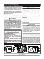
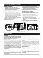
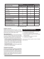
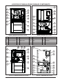
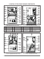
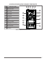
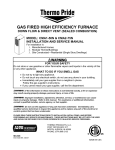
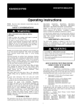
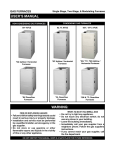
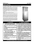
Single Stage, Two-Stage, and Modulating Furnaces GAS FURNACES USER MANUAL 80+ AFUE High Efficiency Furnaces 92.1% AFUE Condensing Furnaces *SA/*TA Upflow/Horizontal *SC Upflow/Horizontal *SK/*TK Downflow *SL Downflow 95.1% AFUE Condensing Furnaces *TC Upflow/Horizontal *TL Downflow 97%+ AFUE Modulating Furnaces *MQ Upflow/Horizontal WARNING: FIRE OR EXPLOSION HAZARD • Failure to follow safety warnings exactly could result in serious injury or property damage. • Installation and service must be performed by a qualified installer, service agency or the gas supplier. • Do not store or use gasoline or other flammable vapors and liquids in the vicinity of this or any other appliance. WHAT TO DO IF YOU SMELL GAS • Do not try to light any appliance. • Do not touch any electrical switch; do not use any phone in your building. • Leave the building immediately. • Immediately call your gas supplier from a neighbors phone. Follow the gas suppliers instructions. • If you cannot reach your gas supplier, call the fire department. READ ALL INSTRUCTIONS THOROUGHLY. KEEP IN A SAFE PLACE FOR FUTURE REFERENCE. 92.1%, 95.1% and 97%+ AFUE Models Only 2 Congratulations on the purchase on your new furnace! With our dedication to quality, superior reliability, and outstanding warranty, we know you will be pleased with this new appliance. This furnace has been designed and built to provide many years of safe and dependable home comfort, providing it is properly installed and regular maintenance has been performed. Improper use or insufficient maintenance can shorten the life of the furnace and result in serious personal injury or property damage. Please read this manual thoroughly and familiarize yourself with the safety, operation and maintenance procedures for this furnace. TABLE OF CONTENTS SAFETY INFORMATION ..............................4 Air for Proper Combustion......................4 Clearances to Combustibles ..................4 Flood Damage .......................................4 Filters .....................................................4 Gas Supply and Piping ..........................5 Inspection...............................................5 Venting System ......................................5 Shutting Down the Furnace ...................5 COMPONENT INFORMATION .....................6 Venting System ......................................6 Category I Furnaces.........................6 Category IV Furnaces ......................6 Thermostats ...........................................6 COMBUSTION AIR REQUIREMENTS .........6 Sources of Corrosion .............................6 Furnace in Small Room or Closet ..........6 INSPECTION.................................................7 Frequency ..............................................7 Venting System ......................................7 Blower and Filter ...................................7 Air for Combustion .................................7 Air for Comfort ........................................7 Maintenance Table ................................8 Burner Operation ..................................8 New Construction ..................................8 Furnace and Air Ducts ...........................8 TROUBLESHOOTING ..................................8 LOCATION OF SINGLE-STAGE FURNACE COMPONENTS .............................................9 LOCATION OF TWO-STAGE FURNACE COMPONENTS ........................................... 10 LOCATION OF MODULATING FURNACE COMPONENTS ........................................... 11 STARTUP AND SHUTDOWN .......................7 Starting the Furnace ..............................7 Shutting Down the Furnace ...................7 3 SAFETY INFORMATION Safety markings are used frequently throughout this manual to designate a degree or level of seriousness and should not be ignored. WARNING indicates a potentially hazardous situation that if not avoided, could result in personal injury or death. CAUTION indicates a potentially hazardous situation that if not avoided, may result in minor or moderate injury or property damage. CLEARANCES TO COMBUSTIBLES The furnace is designed to have certain clearances to combustible items such as wood, paper, etc. Some types of insulation are combustible. If your furnace is installed in an attic, near unfinished walls, or in other insulated space, keep area surrounding the furnace free of insulating material. WARNING: WARNING: The safety information listed below must be followed during the installation, service, and operation of this furnace. Failure to follow safety recommendations could result in possible damage to the equipment, serious personal injury, or death. WARNING: PROPOSITION 65 WARNING: This product contains chemicals known to the state of California to cause cancer, birth defects or other reproductive harm. Do not place combustible materials on or against the furnace cabinet or within 6 inches of the vent pipe. Furnace area must be kept clear and free of combustible materials, gasoline and other flammable vapors and liquids. A fire or explosion may result causing property damage, personal injury or loss of life. Failure to follow the safety warnings exactly could result in serious injury, death or property damage. FLOOD DAMAGE WARNING: WARNING: This furnace is not approved for installation in mobile homes. Installing this furnace in a mobile home could cause fire, property damage, and/or personal injury. AIR FOR PROPER COMBUSTION For proper and safe operation, this furnace requires unrestricted airflow for combustion and ventilation. Do not block or obstruct air openings on the furnace, air openings around the furnace area or the spacings around the furnace. WARNING: Do not reduce the supply of fresh air to the furnace. This could create the production of excessive amounts of Carbon Monoxide - a colorless, odorless gas that is a deadly poison that could result in serious personal injury or death. Do not block any openings that are supplying fresh air to the room or closet the furnace is in. If your furnace obtains its air through a pipe to the outdoors, do not allow the inlet of the pipe to become blocked. 4 Do not use this furnace if any part has been under water. A flood damaged furnace is extremely dangerous. Attempts to use the furnace can result in fire or explosion. A qualified service agency should be contacted to inspect the furnace and to replace all gas controls, control system parts, electrical parts that have been wet or the furnace if deemed necessary. FILTERS WARNING: Never operate the furnace without a filter in place. Accumulating dust in the return air can build up on internal components, resulting in loss of efficiency, equipment damage, and possible fire. • Air filter(s) are not supplied with the furnace as shipped from the factory. The installer must provide a high velocity filter and rack for a filter in the return air duct adjacent to the furnace, or in a return air grill to the furnace. • The furnace should always have a clean filter located either at the air return on the furnace or in an air return register in your habitable space. If the filter becomes dirty, it should be cleaned or replaced. SAFETY INFORMATION • New or newly renovated homes may require more frequent changing until the construction dust has minimized. Filters designed to remove smaller particles such as pollen, may require additional maintenance. WARNING: The furnace was shipped from the factory equipped to operate on natural gas. Conversion to LP/propane gas must be performed by a licensed HVAC technician using a factory supplied conversion kit. Failure to use the proper conversion kit can cause fire, explosion, property damage, carbon monoxide poisoning, personal injury, or death. GAS SUPPLY AND PIPING This furnace does not have a pilot. It is equipped with an ignition device which automatically lights the burner. DO NOT light the burner by hand. IMPORTANT NOTE: Should the gas supply fail to shut off or if overheating occurs, shut off the gas valve to the furnace before shutting off the electrical supply! INSPECTION Your furnace and its venting system should be inspected annually by a licensed HVAC technician. The filter should be inspected at least once a month. See page 7 for Items that should be inspected by the homeowner. WARNING: All gas piping and shutoff valves must be installed in compliance with local codes and utility regulations by licensed installers. DO NOT attempt to modify, or tap into existing gas lines yourself. Fire or explosion may result causing property damage, personal injury or loss of life. Failure to follow the safety warnings exactly could result in serious injury, death or property damage. VENTING SYSTEM WARNING: It is imperative to maintain proper operation of the venting system, including the masonry chimney if applicable. Insufficient venting could create the production of excessive amounts of Carbon Monoxide - a colorless, odorless gas that is a deadly poison that could result in serious personal injury or death. WHAT TO DO IF YOU SMELL GAS • Do not try to light any appliance. • Do not touch any electrical switch; do not use any phone in your building. • Leave the building immediately. • Immediately call your gas supplier from a neighbors phone. Follow the gas suppliers instructions. • If you cannot reach your gas supplier, call the fire department. SHUTTING DOWN THE FURNACE Should you ever need to shut down your furnace for service or maintenance, shut off the gas valve to the furnace before shutting off the electrical service. Your furnace may be equipped with one of three types of gas valves. Remove the door panel from the front of the furnace and determine which valve type matches your installation in Figure 1. Either move the switch or turn the knob to the OFF Position. Additional instructions for shutting down the furnace can be found on page 7. If your installation has a manual gas shutoff valve on the gas supply pipe, shut this off, then shut off the electric to the furnace. Installation and service must be performed by a qualified installer, service agency or the gas supplier. IN ON OFF SINGLE STAGE VALVE TWO - STAGE VALVE MODULATING VALVE Figure 1. Gas Valves 5 COMPONENT INFORMATION The furnace components shown on pages 9 - 11 will help to identify and locate various parts of the furnace. The component you need to familiarize yourself with is the gas valve. You will use this to turn the furnace on and off. There are no user serviceable parts. All repairs must be done by a licensed HVAC technician. VENTING SYSTEM This furnace is designed to fulfill the requirements of being classified as either a Category I or Category IV furnace. These classifications are related to the furnace’s Annual Fuel Utilization Efficiency (AFUE) rating, the percentage of fuel that is converted into usable heating energy. Category I Furnaces These furnaces typically have an AFUE rating of about 80% and may be vented through a properly designed metal vent or masonry chimney. This venting system needs to be primarily vertical, so that the hot combustion products will develop a natural upwards draft action. Category IV Furnaces Category IV furnaces typically have an AFUE rating over 90% and are mainly vented through plastic PVC pipe. These furnaces also produce liquid condensate which is slightly acidic. The vent piping must be sloped upwards away from the furnace to properly drain the condensate back to the condensate disposal system. THERMOSTATS This family of furnaces includes single stage, two-stage and modulating capabilities.These different capabilities require different thermostats to reach their best performance. Single stage furnaces (SA, SK, SC & SL models) should be controlled by a conventional single stage thermostat. Two stage furnaces (TA, TK, TC & TL models) will perform best with a conventional two - stage thermostat. However, it is possible to also control two stage furnaces with a single stage thermostat. Both thermostats are commonly available at your local building supply store. Consult with your installer about which type is best for your installation. The modulating MQ furnaces will not work with a conventional thermostat and must be controlled by an iQ thermostat, available through your dealer. COMBUSTION AIR REQUIREMENTS CAUTION: Do not reduce the supply of fresh air to the furnace. It is extremely important that the furnace receives an unobstructed flow of clean, fresh air to properly burn the fuel gas. If this flow of air is restricted, the partially burned combustion gases may create dangerous amounts of carbon monoxide - a colorless, odorless gas that is a deadly poison that can cause personal injury or death. Air openings on top of the furnace and openings in closet doors or walls must never be restricted. If the furnace is operated without adequate air for combustion, the flame roll-out switch will open, turning off the gas supply to the burners. This indicates that a serious problem with the burners has occurred and must be corrected immediately. Only a licensed HVAC technician can reset this switch. Before remodeling near the furnace, consult with a local code official or the National Fuel Gas Code to make sure you will be in compliance with supplying adequate air for combustion. By erecting new walls, it is sometimes possible to inadvertently restrict the furnace’s air supply. You can find more information about supplying combustion air in the NFGC, which is available at many libraries. 6 SOURCES OF CORROSION It is known that certain common household chemicals can cause heat exchanger corrosion if the vapors are pulled into the furnace’s burners The following is a list of chemicals that should not be used or stored near the furnace. Do not store these chemicals near the furnace: • Permanent wave solutions • Chlorinated waxes and cleaners • Chlorine based swimming pool chemicals • Water softening chemicals • De-icing salts or chemicals • Carbon tetrachloride • Halogen type refrigerants • Cleaning solvents (perchloroethylene) • Printing inks, paint removers, varnishes, etc. • Hydrochloric acid • Cements and glues • Antistatic fabric softeners • Masonry acid washing materials FURNACE IN A SMALL ROOM OR CLOSET If a furnace is installed in relatively small utility room or closet, the installation needs openings in the walls or door to let combustion air in. Make sure that these openings remain unobstructed. Do not modify these openings in any way without consulting a licensed HVAC technician. STARTUP AND SHUTDOWN STARTING THE FURNACE: 1. Make sure the filter is clean and in place. 2. Make sure the vent system is properly installed. 3. Set the thermostat to the lowest setting. 4. Close the manual gas valve outside the furnace. 5. Turn off all electric to the furnace. 6. Remove the door from the burner compartment. 7. Set the gas valve switch or knob to the OFF position. See Figure 2 for gas valve switch or knob location. 8. Wait 5 minutes. If there is any smell of gas, see “WHAT TO DO IF YOU SMELL GAS” on page 5. 9. Set the gas valve switch or knob to the ON position. 10. Turn on all electric to the furnace. 11. Open the manual gas valve. 12. Turn the thermostat back up to force ignition. 13. Observe operation, including burners. If burners fail to ignite, call a licensed HVAC technician. 14. Replace the door on the burner compartment. SHUTTING DOWN THE FURNACE: Should you ever need to shut down your furnace for service or maintenance, follow these steps: 1. 2. 3. 4. 5. Set the thermostat to the lowest setting. Close the manual gas valve outside the furnace. Turn electric to the furnace off. Open the door to the burner compartment. Set the gas valve switch or knob to the OFF position. 6. Replace the door on the burner Compartment. IN ON OFF SINGLE STAGE VALVE TWO - STAGE VALVE MODULATING VALVE Figure 2. Gas Valves INSPECTION FREQUENCY The furnace should be inspected annually by a licensed HVAC technician. Table 1 (page 8) contains suggested inspections and frequency of maintenance. VENTING SYSTEM • Existing masonry chimneys should be inspected and relined if necessary. Vent pipe must slope upwards and be physically sound without holes or corrosion. Any corroded section of vent pipe must be replaced, and any obstruction or blockage must be removed by a licensed HVAC technician. • Flue passageways, the vent system, and the burners should be inspected and cleaned (if required) by a licensed HVAC technician annually to ensure continued safe operation. BLOWER AND FILTER It is recommended that the blower compartment be cleaned of dirt or lint that may have accumulated in the compartment or on the blower and motor as part of the annual inspection. AIR FOR COMBUSTION • For proper and safe operation, the furnace needs air for combustion and ventilation. Do Not block or obstruct air openings on the furnace, or any air openings where the furnace may be installed, including any surrounding spaces. • Direct vent furnaces pull combustion air from the outdoors and vent combustion products back outside. Combustion air coming from the outside needs to be clean of chemicals that can cause corrosion, such as pool chlorinating products. AIR FOR COMFORT • Keep air filters cleaned. It is recommended that the furnace air filter be checked at least once a month. Clean or replace filter to maintain proper airflow and achieve maximum efficiency. • Furniture and drapery should be arranged so that the supply air registers and return grilles are not obstructed. 7 FREQUENCY OF MAINTENANCE BEGINNING OF EACH END OF EACH MONTHLY HEATING SEASON HEATING SEASON MAINTENANCE ITEM Verify furnace area is free of combustible materials. Verify combustion and ventilation air is not restricted. Verify no signs of physical deterioration of the furnace. Verify no obstructions or restrictions in vent or chimney. Verify no holes or cracks in vent pipe. Verify no corrosion in vent pipe. Verify the horizontal vent pipes slope upwards away from furnace. Verify burner flame. Clean or replace filter(s). Clean blower compartment. Clean burner assembly. Clean condensate collection and disposal system (if applicable). X X X X X X X X X X X X X X X X X X X X X X Table 1. Maintenance Table BURNER OPERATION Perform the startup instructions on page 7. The igniter should ignite the closest burner and the flames should quickly carryover to the other burners. The flames should be bright blue, with occasional yellow streaks. NEW CONSTRUCTION The operation of gas furnaces in a construction environment can cause a variety of problems with the furnace. Before occupying the residence, homeowners should have these safety inspections performed by a licensed technician: • The filter must be replaced or cleaned and the furnace must be inspected by a licensed HVAC technician. The furnace must be cleaned and/or repaired if found to be dirty, damaged, or malfunctioning in any way. Before occupancy, the furnace shall be inspected and approved by applicable local authority even if this results in redundant inspections. • The duct work must be inspected and cleaned if found to contain any construction debris. FURNACE AND AIR DUCTS Homeowners should perform frequent visual inspections of the furnace for obvious signs of deterioration. The furnace should be sound without sagging, cracks gaps, etc around the base. The return air duct connection(s) is secured and sealed to the furnace cabinet and terminates outside the area containing the furnace. Any signs of damage or loose connections should be repaired by a qualified HVAC technician. 8 TROUBLESHOOTING If the furnace fails to operate check the following: 1. Is the thermostat setting correct? 2. Are the blower compartment door(s) in place? 3. Has the circuit breaker tripped or the control board fuse burned open? 4. Is the gas turned on at the manual shutoff? 5. Is the filter dirty or clogged? If the furnace still doesn’t operate, contact a licensed HVAC technician LOCATION OF SINGLE-STAGE FURNACE COMPONENTS 1 11 HEAT COOL FAN 24V 9 14 13 5 180 120 90 60 14 LOW ML MH HIGH EAC L1 XFMR HUM NEUTRALS 6 3 5 2 4 1 FLAME BLOWER OFF DELAY L1A LOW ML MH HIGH EAC L1 XFMR HUM NEUTRALS 7 STATUS HEAT COOL FAN 9 6 3 8 5 2 7 4 1 24V 180 120 90 60 L1A 6 3 5 2 4 1 FLAME BLOWER OFF DELAY R C Y G W R C Y G W 12 7 STATUS 9 6 3 8 5 2 7 4 1 2 13 6 4 10 8 11 9 12 6 5 8 10 3 2 3 1 *SA 80+ Upflow/Horizontal Gas Furnace ITEM COMPONENT ITEM 5 *SK 80+ Downflow Gas Furnace COMPONENT ITEM 1 Blower Assembly 2 Blower Door Switch 6 Flame Sensor 3 Burner Assembly 7 Furnace Control Board 4 Combustion Tube 8 Gas Manifold 12 Limit Switch 6 Flame Rollout Switch 5 9 COMPONENT 3 ITEM COMPONENT Gas Valve 13 Pressure Switch 10 Igniter 14 Transformer 11 Inducer Assembly 1 8 10 9 7 7 14 11 12 2 13 12 12 14 13 11 2 1 *SC 92.1% Upflow/Horizontal Gas Furnace 12 13 5 9 10 6 3 8 *SL 92.1% Downflow Gas Furnace 9 LOCATION OF TWO-STAGE FURNACE COMPONENTS 1 11 7 12 7 9 16 13 14 15 5 2 16 4 15 11 9 6 8 10 3 2 12 6 1 13 14 5 8 10 3 *TA 80+ Upflow/Horizontal Gas Furnace ITEM COMPONENT ITEM *TK 80+ Downflow Gas Furnace COMPONENT ITEM COMPONENT ITEM COMPONENT 1 Blower Assembly 5 Flame Rollout Switch 9 Gas Valve 13 Motor Choke 2 Blower Door Switch 6 Flame Sensor 10 Igniter 14 Motor Control Board 3 Burner Assembly 7 Furnace Control Board 11 Inducer Assembly 15 Pressure Switch 4 Combustion Tube 8 Gas Manifold 12 Limit Switch 16 Transformer 9 5 8 10 3 1 7 13 6 14 7 15 2 16 11 12 15 12 2 16 1 13 14 11 9 12 5 8 6 3 *TC 95.1% Upflow/Horizontal Gas Furnace 10 *TL 95.1% Downflow Gas Furnace LOCATION OF MODULATING FURNACE COMPONENTS ITEM COMPONENT NAME 1. Blower Assembly 2. Blower Door Switch 3. Burner Assembly 4. Finish Flange 5. Flame Roll-Out Switch 6. Flame Sensor 7. Furnace Control Board 8. Gas Manifold 9. Gas Valve 10. Igniter 11. Inducer Assembly 12. Inducer Limit Switch 13. Motor Choke 14. Motor Control Board 15. Motor Control Box 16. Pressure Switches 17. Transformer 4 6 5 8 3 10 16 9 11 7 12 17 2 (C and D cabinets only) 15 1 13 14 *MQ 97%+ Upflow/Horizontal Gas Furnace 11 ¢708967`¤ O’Fallon, MO 708967 7089670 Specifications and illustrations subject to change without notice or incurring obligations. Printed in U.S.A. (10/08)