1
1
/4 -DIN, 1/8 -DIN & 1/16 -DIN Controllers & Indicators - Product Manual
1
1
1
/4, /8 and /16 DIN Plus Series
Controllers & Indicators
User Guide
Manual Part Number: 59305-6
Price: £12.00
$20.00
€18.00
1
/4 -DIN, 1/8 -DIN & 1/16 - DIN Controllers & Indicators - Product Manual
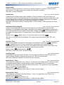
This manual supplements the Concise Product manual supplied with each instrument at the
time of shipment. Information in this installation, wiring and operation manual is subject to
change without notice.
Copyright © March 2006, Danaher Corporation, all rights reserved. No part of this
publication may be reproduced, transmitted, transcribed or stored in a retrieval system, or
translated into any language in any form by any means without the written permission of
West Instruments.
Copies of this manual are available in electronic format on the West Instruments web site
(www.westinstruments.com) Printed versions are available from West or its agents at the
price published on the front cover.
Note:
It is strongly recommended that applications incorporate a high or low limit protective
device, which will shut down the equipment at a preset process condition in order to
prevent possible damage to property or products.
WARNING:
THE INTERNATIONAL HAZARD SYMBOL IS INSCRIBED ADJACENT TO THE REAR
CONNECTION TERMINALS. IT IS IMPORTANT TO READ THIS MANUAL BEFORE
INSTALLING OR COMMISSIONING THE UNIT.
Products covered by this manual are suitable for Indoor use, Installation Category II,
Pollution category 2 environments.
This user guide covers the West plus series product range.
Products covered in this issue of the manual:
P6100, P6120, P8100 & P4100 Process Controllers
P6170, P8170 & P4170 Valve Controllers
P6700, P8700 7 P4700 Limit Controllers
P6010 & P8010 Indicators
59305, Issue 6 – March 2006
Page iii
1
/4 -DIN, 1/8 -DIN & 1/16 - DIN Controllers & Indicators - Product Manual
Warranty and Returns Statement
These products are sold by West Instruments under the warranties set forth in the following
paragraphs. Such warranties are extended only with respect to a purchase of these products,
as new merchandise, directly from West Instruments or from a West Instruments distributor,
representative or reseller and are extended only to the first buyer thereof who purchases
them other than for the purpose of resale.
Warranty
These products are warranted to be free from functional defects in material and workmanship
at the time the products leave West Instruments factory and to conform at that time to the
specifications set forth in the relevant West instruction manuals sheet or sheets, for such
products for a period of three years.
THERE ARE NO EXPRESSED OR IMPLIED WARRANTIES, WHICH EXTEND BEYOND THE
WARRANTIES HEREIN AND ABOVE SET FORTH. WEST MAKES NO WARRANTY OF
MERCHANTABILITY OR FITNESS FOR A PARTICULAR PURPOSE WITH RESPECT TO THE
PRODUCTS.
Limitations
West shall not be liable for any incidental damages, consequential damages, special
damages, or any other damages, costs or expenses excepting only the cost or expense of
repair or replacement as described above. Products must be installed and maintained in
accordance with West Instruments instructions. There is no warranty against damage to the
product resulting from corrosion. Users are responsible for the suitability of the products to
their application.
For a valid warranty claim, the product must be returned carriage paid to the supplier within
the warranty period. The product must be properly packaged to avoid damage from
Electrostatic Discharge or other forms of harm during transit.
Page iv
59305, Issue 6 – March 2006
1
/4 -DIN, 1/8 -DIN & 1/16 - DIN Controllers & Indicators - Product Manual
Contents
Page Number:
Warranty and Returns Statement ...................................................................................................... iv
1
Introduction............................................................................................................................. 10
2
Installation............................................................................................................................... 11
Unpacking .................................................................................................................................................11
Installation .................................................................................................................................................11
Panel Cut-outs ..........................................................................................................................................12
Panel-Mounting .........................................................................................................................................12
3
Plug-in Options....................................................................................................................... 14
Options Modules and Functions ...............................................................................................................14
Auto Detection of Option Modules ............................................................................................................14
Preparing to Install or Remove Options Modules .....................................................................................16
Removing/Replacing Option Modules ......................................................................................................16
Replacing the Instrument in its Housing ...................................................................................................19
4
Wiring Instructions................................................................................................................. 20
Installation Considerations........................................................................................................................20
AC Power Wiring - Neutral (for 100 to 240V AC versions) .......................................................................20
Wire Isolation ............................................................................................................................................20
Use of Shielded Cable ..............................................................................................................................21
Noise Suppression at Source ...................................................................................................................21
Sensor Placement (Thermocouple or RTD) .............................................................................................22
Thermocouple Wire Identification Chart ...................................................................................................22
Connections and Wiring............................................................................................................................23
Power Connections - Mains Powered Instruments .............................................................................25
Power Connections - 24/48V AC/DC Powered Instruments ..............................................................25
Universal Input Connections - Thermocouple (T/C)............................................................................26
Universal Input Connections – PT100 (RTD) input .............................................................................26
Universal Input Connections - Linear Volt, mV or mA input ................................................................27
Option Slot 1 – Relay Output Module..................................................................................................27
Option Slot 1 - SSR Driver Output Module..........................................................................................28
Option Slot 1 - Triac Output Module....................................................................................................28
Option Slot 1 - Linear Voltage or mADC Output module.....................................................................28
Option Slot 2 - Relay Output Module...................................................................................................29
Option Slot 2 - SSR Driver Output Module..........................................................................................29
Option Slot 2 - Triac Output Module....................................................................................................29
Option Slot 2 - Dual Relay Output Module ..........................................................................................30
Option Slot 2 - Linear Voltage or mADC Output module.....................................................................30
Option Slot 3 - Relay Output Module...................................................................................................31
Option Slot 3 - SSR Driver Output Module..........................................................................................31
59305, Issue 6 – March 2006
Page 1
1
/4 -DIN, 1/8 -DIN & 1/16 - DIN Controllers & Indicators - Product Manual
Option Slot 3 - Linear Voltage or mADC Output module.................................................................... 31
Option Slot 3 - Dual Relay Output Module ......................................................................................... 32
Option Slot 3 - Transmitter Power Supply Module ............................................................................. 32
Option Slot A Connections - RS485 Serial Communications Module ................................................ 33
Option Slot A Connections - Digital Input Module .............................................................................. 33
Option Slot A Connections – Basic Auxiliary Input Module ................................................................ 33
Option Slot B Connections – Digital Input 2 (Full Auxiliary Module) .................................................. 34
Option Slot B Connections – 1/4 DIN & 1/8 DIN Full Auxiliary Input Module........................................ 34
5
Powering Up ........................................................................................................................... 35
Powering Up Procedure ............................................................................................................................35
Overview Of Front Panel...........................................................................................................................35
Displays.....................................................................................................................................................36
Keypad ......................................................................................................................................................36
LED Functions...........................................................................................................................................36
6
Messages and Error Indications........................................................................................... 37
7
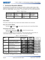
Instrument Operation Modes ................................................................................................ 38
Select Mode ..............................................................................................................................................38
Entry into the Select Mode ................................................................................................................. 38
Navigating in Select Mode .................................................................................................................. 38
Unlock Codes............................................................................................................................................39
Automatic Tune Mode ...............................................................................................................................39
Navigating in Automatic Tune Mode................................................................................................... 39
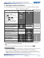
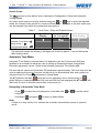
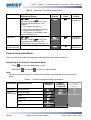
Product Information Mode.........................................................................................................................40
Navigating in the Product Information Mode ...................................................................................... 40
Lock Code View ........................................................................................................................................42
Entry and Navigating in Lock Code View Mode ................................................................................. 42
8
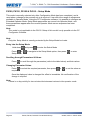
P6100, P6120, P8100 & P4100 Controller – Model Group................................................... 43
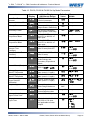
P6100, P8100 & P4100 Controllers - Configuration Mode .......................................................................43
Entry into the Configuration Mode ...................................................................................................... 43
Scrolling through Parameters and Values .......................................................................................... 43
Changing Parameter Values .............................................................................................................. 44
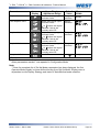
P6100, P6120, P8100 & P4100 – Setup Mode ........................................................................................50
Entry into the Setup Mode .................................................................................................................. 50
Scrolling through Parameters & Values.............................................................................................. 50
Changing Parameter Values .............................................................................................................. 50
P6100, P8100 & P4100 Controllers - Operator Mode ..............................................................................54
P6100, P8100 & P4100 Controllers – Extended Operator Mode....................................................... 54
Navigating in Operator Mode.............................................................................................................. 54
Adjusting the Local Setpoint(s) .................................................................................................................56
Adjusting the Setpoint Ramp Rate............................................................................................................56
Page 2
59305, Issue 6 – March 2006
1
/4 -DIN, 1/8 -DIN & 1/16 - DIN Controllers & Indicators - Product Manual
Manual Control Mode................................................................................................................................57
Selecting/deselecting Manual Control Mode .......................................................................................57
P6100, P6120, P8100 & P4100 Controllers –Communications Parameters............................................58
Bit Parameters.....................................................................................................................................58
Word Parameters ................................................................................................................................58
9
P6170, P8170 & P4170 VMD Controller – Model Group ...................................................... 63
Special Wiring Considerations for Valve Motor Control............................................................................63
P6170, P8170 & P4170 VMD Controllers - Configuration Mode ..............................................................64
Entry into the Configuration Mode.......................................................................................................64
Scrolling through Parameters and Values...........................................................................................64
Changing Parameter Values ...............................................................................................................64
P6170, P8170 & P4170 – Setup Mode.....................................................................................................72
Entry into the Setup Mode ...................................................................................................................72
Scrolling through Parameters & Values ..............................................................................................72
Changing Parameter Values ...............................................................................................................72
Adjusting the Valve Parameters................................................................................................................72
Set Valve Opened Position & Set Valve Closed Position ...................................................................73
Valve Position Clamping......................................................................................................................73
P6170, P8170 & P4170 Controllers - Operator Mode ..............................................................................76
P6170, P8170 & P4170 Controllers – Extended Operator Mode........................................................76
Navigating in Operator Mode...............................................................................................................76
Adjusting the Local Setpoint(s) .................................................................................................................78
Adjusting the Setpoint Ramp Rate............................................................................................................78
Manual Control Mode................................................................................................................................79
Selecting/deselecting Manual Control Mode .......................................................................................79
P6170, P8170 & P4170 Controllers – Serial Communications Parameters.............................................80
Bit Parameters.....................................................................................................................................80
Word Parameters ................................................................................................................................80
10
P6700, P8700 & P4700 Limit Controller – Model Group...................................................... 83
P6700, P8700 & P4700 Limit Controllers - Configuration Mode ..............................................................83
Entry into the Configuration Mode.......................................................................................................83
Scrolling through Parameters and Values...........................................................................................83
Changing Parameter Values ...............................................................................................................84
P6700, P8700 & P4700 Limit Controllers – Setup Mode..........................................................................89
Entry into the Setup Mode ...................................................................................................................89
Scrolling through Parameters & Values ..............................................................................................89
Changing Parameter Values ...............................................................................................................89
P6700, P8700 & P4700 Limit Controllers - Operator Mode......................................................................91
Navigating in Operator Mode...............................................................................................................91
Limit Setpoint Adjustment .........................................................................................................................92
59305, Issue 6 – March 2006
Page 3
1
/4 -DIN, 1/8 -DIN & 1/16 - DIN Controllers & Indicators - Product Manual
Exceed Condition ......................................................................................................................................92
Limit Output Function ................................................................................................................................92
Limit Annunciator Outputs.........................................................................................................................92
Resetting Limit Outputs & Annunciators ...................................................................................................92
Using The Reset Key To Reset Limit Outputs & Annunciators ......................................................... 92
Resetting Limit Hold and Exceed Time.....................................................................................................93
To reset the stored Limit Hold and Exceed Time values.................................................................... 93
P6700, P8700 & P4700 Controllers – Serial Communications Parameters .............................................94
Bit Parameters .................................................................................................................................... 94
Word Parameters................................................................................................................................ 94
11
P6010 & P8010 Indicator – Model Group ............................................................................. 98
P6010 & P8010 Indicators - Configuration Mode .....................................................................................98
Entry into the Configuration Mode ...................................................................................................... 98
Scrolling through Parameters and Values .......................................................................................... 99
Changing Parameter Values .............................................................................................................. 99
P6010 & P8010 Indicators - Setup Mode................................................................................................106
Entry into the Setup Mode ................................................................................................................ 106
Scrolling through Parameters and Values ........................................................................................ 106
Changing Parameter Values ............................................................................................................ 106
P6010 & P8010 Indicators - Operator Mode...........................................................................................110
Entry into Operator Mode ................................................................................................................ 110
Scrolling through Parameters and Values ........................................................................................ 110
Changing Parameter Values ............................................................................................................ 110
1
/8 Din Indicator Units Display .................................................................................................................112
Alarm Indications.....................................................................................................................................112
Resetting Latched Alarm Outputs ...........................................................................................................112
Resetting Alarm 1 Active Time, Minimum PV or Maximum PV ..............................................................112
Multi-Point Scaling ..................................................................................................................................113
Tare Feature ...........................................................................................................................................113
P6010 & P8010 Indicators – Serial Communications Parameters .........................................................114
Bit Parameters .................................................................................................................................. 114
Word Parameters.............................................................................................................................. 115
12
Manually Tuning Controllers............................................................................................... 118
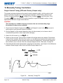
Single Control Tuning (PID with Primary Output only)............................................................................118
Dual Control Tuning (PID with Primary and Secondary Outputs)...........................................................119
Valve Control Tuning (PI with VMD or Linear Outputs) ..........................................................................119
Manually Fine Tuning..............................................................................................................................121
13
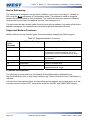
Modbus Serial Communications ........................................................................................ 122
Physical Layer.........................................................................................................................................122
Link Layer................................................................................................................................................123
Page 4
59305, Issue 6 – March 2006
1
/4 -DIN, 1/8 -DIN & 1/16 - DIN Controllers & Indicators - Product Manual
Device Addressing ..................................................................................................................................124
Supported Modbus Functions .................................................................................................................124
Function Descriptions .............................................................................................................................124
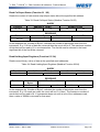
Read Coil/Input Status (Function 01 / 02) .........................................................................................125
Read Holding/Input Registers (Function 03 / 04) ..............................................................................125
Force Single Coil (Function 05) .........................................................................................................126
Pre-Set Single Register (Function 06)...............................................................................................126
Loopback Diagnostic Test (Function 08)...........................................................................................126
Pre-Set Multiple Registers (Function 10 Hex) ...................................................................................127
Exception Responses........................................................................................................................127
14
ASCII Communications........................................................................................................ 128
Physical Layer.........................................................................................................................................128
Device Addressing ..................................................................................................................................128
Session Layer .........................................................................................................................................128
Type 1 Message ................................................................................................................................129
Type 2 Message ................................................................................................................................130
Type 3 Message ................................................................................................................................130
Type 4 Message ................................................................................................................................131
Error Response .......................................................................................................................................131
15
Calibration Mode .................................................................................................................. 132
Equipment Required For Checking or Calibrating the Universal Input ...................................................132
Calibration Check....................................................................................................................................132
Recalibration Procedure .........................................................................................................................133
16
Appendix 1 – Glossary......................................................................................................... 134
Active Setpoint
Type: Controller Definition..........................................................................................134
Actual Setpoint
Type: Controller Definition.........................................................................................134
Alarm Hysteresis
Type: General Parameter.......................................................................................135
Alarm Operation
Type: General Definition ..........................................................................................136
Alarm Inhibit
Type: General Parameter ...............................................................................................137
Annunciator
Type: Limit Controller Definition ......................................................................................137
Automatic Reset (Integral)
Type: Controller Tuning Parameter .........................................................137
Auto Pre-Tune
Type: Controller Tuning Parameter............................................................................137
Auxiliary Input
Type: General Definition .............................................................................................137
Band Alarm 1 Value
Type: General Parameter...................................................................................137
Band Alarm 2 Value
Type: General Parameter...................................................................................137
Bias (Manual Reset)
Type: Controller Tuning Parameter ...................................................................138
Bumpless Transfer
Type: Controller Definition....................................................................................138
Boundless VMD Control
Cascade Control
Type: VMD Controller Definition ..................................................................138
Type: Controller Definition .......................................................................................138
Communications Write Enable
59305, Issue 6 – March 2006
Type: General Definition ....................................................................139
Page 5
1
/4 -DIN, 1/8 -DIN & 1/16 - DIN Controllers & Indicators - Product Manual
Control Type
Controller
CPU
Type: Controller Parameter............................................................................................139
Type: Controller Definition ..................................................................................................139
Type: General Definition............................................................................................................139
Current Proportioning Control
Type: Controller Definition...................................................................139
Cycle Time
Type: Controller Definition ................................................................................................139
Deadband
Type: Controller Parameter...............................................................................................140
Derivative
Type: Controller Parameter ................................................................................................140
Deviation Alarm 1 Value Type
Deviation Alarm 2 Value
Type: General Parameter ...................................................................140
Type: General Parameter ............................................................................140
Differential (On-Off Hysteresis)
Type: Controller Parameter...............................................................140
Direct/Reverse Action of Control Outputs
Display Strategy
Elapsed Time
Type: General Parameter.........................................................................................140
Type: Indicator Definition..............................................................................................141
Exceed Condition
Exceed Time
Indicator
Type: Limit Controller Definition .............................................................................141
Type: Limit Controller Definition ....................................................................................141
Type: Indicator Definition ......................................................................................................141
Input Filter Time Constant
Input Range
Input Span
Integral
Type: General Parameter..........................................................................141
Type: General Definition .................................................................................................141
Type: General Definition ...................................................................................................141
Type: Controller Tuning Parameter .......................................................................................141
Latching Relay
LED
Type: General Definition .............................................................................................142
Type: General Definition............................................................................................................142
Limit Controller
Type: Limit Controller Definition .................................................................................142
Limit Hysteresis
Type: Limit Controller Definition ................................................................................142
Limit Setpoint
Lock Codes
Type: Limit Controller Definition....................................................................................142
Type: General Parameter ...............................................................................................142
Logical Combination of Alarms
Loop Alarm Enable
Loop Alarm Time
mADC
Type: General Definition...................................................................143
Type: Controller Parameter.................................................................................143
Type: Controller Parameter.....................................................................................144
Type: General Definition .........................................................................................................144
Manual Mode
Type: Controller Definition ............................................................................................144
Manual Mode Enable
Master & Slave
Type: Controller Parameter ..............................................................................145
Type: Controller Definition..........................................................................................145
Minimum Motor On Time
Type: VMD Controller Parameter ...............................................................145
Modulating Valve
Type: VMD Controller Definition .............................................................................145
Motor Travel Time
Type: VMD Controller Parameter ..........................................................................146
Multi-Point Scaling Enable
Type: Indicator Parameter........................................................................146
Multi-Point Scaling Set Up
Type: Indicator Parameter ........................................................................146
Offset
Type: Controller Parameter.......................................................................................................147
On-Off Control
Page 6
Type: Controller Definition.................................................140
Type: Controller Definition..........................................................................................147
59305, Issue 6 – March 2006
1
/4 -DIN, 1/8 -DIN & 1/16 - DIN Controllers & Indicators - Product Manual
On-Off Differential (Hysteresis)
Open Loop VMD
Type: VMD Controller Definition .............................................................................147
Overlap/Deadband
PI Control
Type: Controller Parameter.................................................................................147
Type: Controller Definition ..................................................................................................148
PID Control
PLC
Type: Controller Parameter..............................................................147
Type: Controller Definition ..............................................................................................148
Type: General Definition ...........................................................................................................149
Pre-Tune
Type: Controller Definition ..................................................................................................149
Primary Output Power Limit
Type: Controller Parameter ....................................................................150
Primary Proportional Band
Type: Controller Tuning Parameter.........................................................150
Process High Alarm 1 Value
Type: General Parameter.....................................................................150
Process High Alarm 2 Value
Type: General Parameter.....................................................................150
Process Low Alarm 1 Value
Type: General Parameter......................................................................150
Process Low Alarm 2 Value
Type: General Parameter......................................................................150
Process Variable (PV)
Type: General Definition .................................................................................151
Process Variable Offset
Rate (Derivative)
Type: General Parameter ............................................................................151
Type: Controller Tuning Parameter ........................................................................151
Remote Setpoint (RSP)
Type: Controller Definition ............................................................................151
Remote Auxiliary Input Range
Type: Controller Parameter ................................................................151
Remote Setpoint Lower Limit
Type: Controller Parameter.................................................................151
Remote Setpoint Upper Limit
Type: Controller Parameter.................................................................152
Remote Setpoint Offset
Retransmit Output
Type: Controller Parameter..........................................................................152
Type: General Definition ......................................................................................152
Retransmit Output 1 Scale Maximum
Type: General Parameter........................................................152
Retransmit Output 1 Scale Minimum
Type: General Parameter........................................................152
Retransmit Output 2 Scale Maximum
Type: General Parameter.......................................................153
Retransmit Output 2 Scale Minimum
Type: General Parameter........................................................153
Retransmit Output 3 Scale Maximum
Type: General Parameter.......................................................153
Retransmit Output 3 Scale Minimum
Type: General Parameter........................................................153
Reset
Type: Controller Tuning Parameter..........................................................................................153
Reverse Acting
Type: Controller Definition ........................................................................................153
Scale Range Upper Limit
Type: General Parameter..........................................................................153
Scale Range Lower Limit
Type: General Parameter..........................................................................154
Secondary Proportional Band
Self-Tune
Type: Controller Tuning Parameter....................................................154
Type: Controller Tuning Definition .....................................................................................154
Serial Communications Option
Type: General Definition ....................................................................155
Set Valve Closed Position
Type: VMD Controller Parameter .............................................................155
Set Valve Opened Position
Type: VMD Controller Parameter ............................................................155
Setpoint
Type: Controller Definition....................................................................................................155
Setpoint Upper Limit
Type: Controller Parameter ...............................................................................156
Setpoint Lower Limit
Type: Controller Parameter ..............................................................................156
Setpoint Ramping Enable
59305, Issue 6 – March 2006
Type: Controller Parameter ......................................................................156
Page 7
1
/4 -DIN, 1/8 -DIN & 1/16 - DIN Controllers & Indicators - Product Manual
Setpoint Ramp Rate
Setpoint Select
Type: Controller Parameter...............................................................................156
Type: Controller Parameter .......................................................................................157
Setpoint Select Enable
Type: Controller Parameter...........................................................................157
Solid State Relay (SSR)
Type: General Definition .............................................................................157
Solenoid Valve
Tare
Type: General Definition............................................................................................157
Type: Indicator Parameter.........................................................................................................158
Three Point Stepping Control
Time Proportioning Control
Tuning
Triac
Type: VMD Controller Definition .........................................................158
Type: Controller Definition......................................................................158
Type: Controller Definition ......................................................................................................158
Type: General Definition...........................................................................................................158
Valve Close Limit
Type: VMD Controller Parameter ...........................................................................159
Valve Motor Drive Control
Type: VMD Controller Definition................................................................159
Valve Position or Flow Indication
Valve Open Limit
VMD
17
Type: VMD Controller Definition....................................................159
Type: VMD Controller Parameter............................................................................159
Type: VMD Controller Parameter ..............................................................................................160
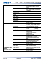
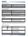
Appendix 2 - Specification .................................................................................................. 161
Universal Input ........................................................................................................................................161
General Input Specifications............................................................................................................. 161
Thermocouple................................................................................................................................... 161
Thermocouple Ranges Available............................................................................................................. 161
Thermocouple Performance .................................................................................................................... 162
Resistance Temperature Detector (RTD)......................................................................................... 162
RTD Ranges Available............................................................................................................................. 162
RTD Performance .................................................................................................................................... 163
DC Linear.......................................................................................................................................... 163
DC Linear Ranges Available.................................................................................................................... 163
DC Linear Performance ........................................................................................................................... 163
Auxiliary Inputs........................................................................................................................................164
Digital Inputs ...........................................................................................................................................164
Output Specifications ..............................................................................................................................165
Output Module Types ....................................................................................................................... 165
Specifications of Output Types......................................................................................................... 165
Control Specifications .............................................................................................................................167
Process Alarms .......................................................................................................................................167
Digital Communications ..........................................................................................................................167
Reference Conditions..............................................................................................................................168
Operating Conditions ..............................................................................................................................168
Standards ................................................................................................................................................168
Physical Specifications............................................................................................................................168
18
Page 8
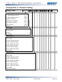
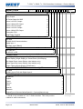
Appendix 3 - Product Coding.............................................................................................. 169
59305, Issue 6 – March 2006
1
/4 -DIN, 1/8 -DIN & 1/16 - DIN Controllers & Indicators - Product Manual
How to use this manual
This manual is structured to give easy access to the information required for all aspects of
the installation and use and of the products:
Section 1:
Introduction - A brief description of the product range.
Section 2:
Installation - Unpacking, installing and panel mounting instructions.
Section 3:
Plug-in Options - Installation of the plug-in option modules.
Section 4:
Wiring Guidelines - Guidance on good wiring practice, noise avoidance, wiring
diagrams and input/output connections.
Section 5:
Powering Up - Powering up procedure and descriptions of displays & switches.
Section 6:
Messages & Error Indications - Display Messages and fault indications.
Section 7:
Operation Modes - Describes operating modes common across the range.
These include Select Mode for gaining access to the Setup and Configuration menus,
Automatic tuning on controllers and the Product information menus.
Section 8:
P6100, P6120, P8100 & P4100 Model Group - Describes unique operating
features of these process controllers. It covers the Configuration, Setup & Operator menus,
Communications parameters, adjusting Setpoint, use of Manual Control and PID auto-tuning.
Section 9:
P6170, P8170 & P4170 Model Group - Describes unique operating features of
these valve motor controllers. It covers the Configuration, Setup & Operator menus,
Communications parameters, adjusting Setpoint, use of Manual Control and PID auto-tuning.
Section 10: P6700, P8700 & P4700 Model Group - Describes unique operating features of
these limit controllers. It covers the Configuration, Setup & Operator menus, Communications
parameters, adjusting the Limit Setpoint and resetting the Limit Output.
Section 11: P6010 & P8010 Model Group - Describes unique operating features of these
indicators. It covers the Configuration, Setup & Operator menus, Communications
parameters, using the Tare and Multi-Point Scaling Functions.
Section 12: Manually Tuning Controllers - Advice on manually adjusting the Process and
Valve Controllers tuning parameters.
Section 13: Modbus Serial Communications - Details the physical layer and message
formats used for the Modbus communications protocol common to all products in the range.
Section 14: ASCII Serial Communications - Details the physical layer and message
formats used for the ASCII serial communications protocol available on some products.
Section 15: Calibration Mode - Step-by-step instructions to calibrate the instrument. This
section is intended for use by suitably qualified personnel.
Appendix 1: Glossary - Explanations of the terms used and product features.
Appendix 2: Specification - Technical specifications for all products in the range.
Appendix 3: Product Coding - Product model/ordering codes.
59305, Issue 6 – March 2006
Page 9
1
/4 -DIN, 1/8 -DIN & 1/16 - DIN Controllers & Indicators - Product Manual
1 Introduction
These instruments are microprocessor based indicators, process and valve controllers, and
indicators. They can measure, display or control process variables such as temperature,
pressure, flow and level from a variety of inputs. Models are available in three sizes. 1/16 DIN
(48 x 48mm front). 1/8 DIN (48 x 96mm front) and 1/4 DIN (96 x 96mm front).
The operating voltage is either 100-240V at 50/60 Hz or 24V-48V AC/DC depending on the
model purchased. EEPROM technology protects against data or configuration loss during
power outages.
Inputs are user configurable for connection to thermocouple and RTD probes, as well as
linear process signal types such as mVDC, VDC or mADC. Output options include relays,
SSR drivers, triacs or linear mV/voltage modules. These can be used for process control,
valve control, alarms or retransmission of the process variable or setpoint to external devices
such as data recorders or PLC’s. A Transmitter Power Supply option module can provide an
unregulated 24V DC (22mA) auxiliary output voltage for external signal transmitters.
Alarm indication is standard on all instruments; up to five alarms are possible on the
indicators. Alarms may be set as process high or low, deviation (active above or below
controller setpoint), band (active both above and below setpoint), or control loop types.
Models with a heater current input also have high, low or short circuit heater break alarms
based on control load current. These alarms can be linked to any suitable output. Alarm
status is indicated by LED’s or the alarm status screen.
Controllers can be programmed for on-off, time proportioning, or current proportioning control
implementations, depending on the output modules fitted, and feature manual or automatic
tuning of the PID parameters. A secondary control output is available when additional output
modules are fitted. Valve Motor Drive (Three Point Stepping Control) is possible on some
models. Optional analogue controller Remote Setpoint inputs included in the range. Control
functions, alarm settings and other parameters are easily adjusted from the front keypad or
via PC based configuration software.
Limit Controllers shut down a process in order to prevent possible damage to equipment or
products. They have latching relay, which cannot be reset until the process is in a safe
condition. Limit controllers work independently of the normal process controller and have
approvals for safety critical applications.
Indicator models can display a process value and provide multiple stage alarm outputs.
Additional features include Multipoint scaling to compensate for non-linear signals and a Tare
function to auto-zero the current reading.
Page 10
Introduction
59305-6, Issue 6 – March 2006
1
/4 -DIN, 1/8 -DIN & 1/16 - DIN Controllers & Indicators - Product Manual
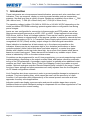
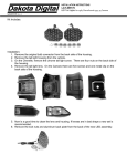
2 Installation
Unpacking
1. Remove the product from its packing. Retain the packing for future use, in case it is
necessary to transport the instrument to a different site or to return it to the supplier for
repair/testing.
2. The instrument is supplied with a panel gasket and push fit fixing strap. A single sheet
concise manual is also supplied in one or more languages. Examine the delivered items
for damage or defects. If any are found, contact your supplier immediately.
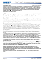
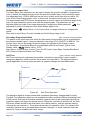
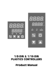
Installation
CAUTION:
Installation and configuration should be performed only by personnel who are
technically competent and authorised to do so. Local regulations regarding
electrical installation and safety must be observed.
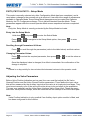
1
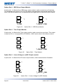
/4 - DIN & 1/16 - DIN Instruments
1
/8 - DIN Instruments
Figure 1. Main dimensions
59305, Issue 6 – March 2006
Installation
Page 11
1
/4 -DIN, 1/8 -DIN & 1/16 - DIN Controllers & Indicators - Product Manual
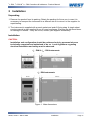
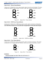
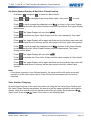
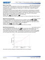
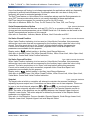
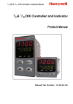
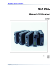
Panel Cut-outs
The mounting panel must be rigid and may be up to 6.0mm (0.25 inches) thick. The cut-outs
required for the instruments are shown below.
1
/4 DIN
1
1
/8 DIN
/16 DIN
92mm
92mm
+0.5 –0.0
+0.5 –0.0
(45mm for
45mm
indicator)
+0.5 –0.0
92mm
45mm +0.5 –0.0
45mm
+0.5 –0.0
(92mm for indicator)
+0.5 –0.0
Figure 2. Panel cut-out sizes
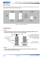
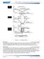
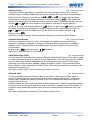
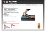
Panel-Mounting
CAUTION:
Ensure the inside of the panel is with the instruments operating temperature and
that there is adequate air flow to prevent overheating.
Slide mounting clamp over the
instrument housing, towards rear face of
mounting panel, until the tongues
Mounting Panel
engage in ratchets and instrument is
Instrument Housing
clamped in position.
Ratchets
Gasket
Hold firmly in position
(apply pressure to bezel only)
Figure 3. Panel-Mounting the instrument
CAUTION:
Do not remove the panel gasket, as this may result in inadequate clamping and
sealing of the instrument to the panel.
Page 12
Installation
59305, Issue 6 – March 2006
1
/4 -DIN, 1/8 -DIN & 1/16 - DIN Controllers & Indicators - Product Manual
Once the instrument is installed in its mounting panel, it may be subsequently removed from
it’s housing, if necessary, as described in the Fitting and Removing Option Modules section.
Instruments may be mounted side-by-side in a multiple installation, but instrument to panel
moisture and dust sealing will be compromised. The cut-out width (for n instruments) is
shown below.
1
/8 - & 1/16 - DIN Instruments (excluding 1/8 - DIN Indicators):
(48n - 4) mm or (1.89n - 0.16) inches.
1
/4 - DIN Instruments & 1/8 - DIN Indicators:
(96n - 4) mm or (3.78n - 0.16) inches
If panel sealing must be maintained, mount each instrument into an individual cut-out with
6mm or more clearance between the edges of the holes.
Note:
The mounting clamp tongues may engage the ratchets either on the sides or the
top/bottom faces of the Instrument housing. When installing several Instruments side-byside in one cut-out, use the ratchets on the top/bottom faces.
59305, Issue 6 – March 2006
Installation
Page 13
1
/4 -DIN, 1/8 -DIN & 1/16 - DIN Controllers & Indicators - Product Manual
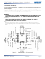
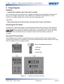
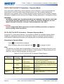
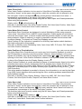
3 Plug-in Options
Options Modules and Functions
A range of plug-in option modules is available to add additional input, output and
communication functions to the instruments in the range. These modules can be either preinstalled at the time of manufacture, or retrofitted in the field.
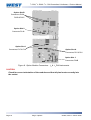
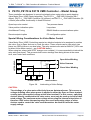
The modules are installed between the instruments main circuit boards into the four option
slots. These are designated as Slots 1, 2, 3, A & B. Installation is detailed below.
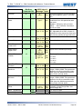
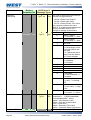
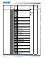
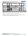
Note:
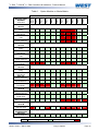
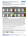
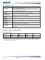
Slot 1 modules cannot be fitted into Slot 2 or 3. Slot 2 & 3 modules cannot be fitted into
Slot 1. Some Slot 2 &3 modules should only be fitted into one of the two slots. This is
detailed in the - Option Module vs. Model Matrix below.
PSU BOARD
CPU BOARD
Figure 4. Typical rear view (uncased) & main board positions
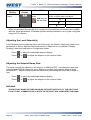
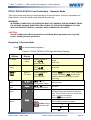
Auto Detection of Option Modules
The instrument automatically detects which option modules have been fitted into each slot.
In Configuration Mode, the menus will change to reflect the options compatible with the
hardware fitted. The modules fitted can be viewed in the products information menu, as
detailed in the Product Information Mode section of this manual.
Page 14
Plug-in Options
59305, Issue 6 – March 2006
1
/4 -DIN, 1/8 -DIN & 1/16 - DIN Controllers & Indicators - Product Manual
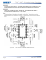
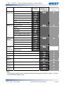
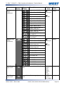
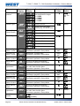
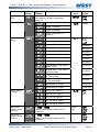
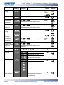
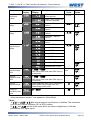
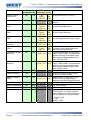
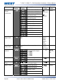
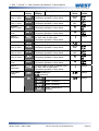
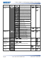
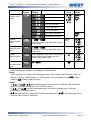
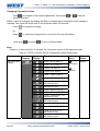
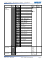
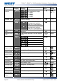
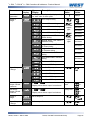
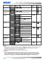
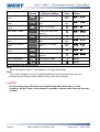
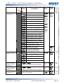
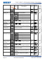
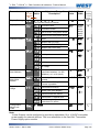
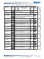
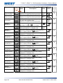
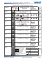
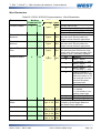
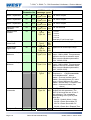
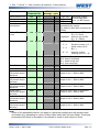
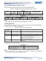
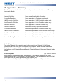
Table 1. Option Module vs. Model Matrix
OPTION
SLOT 1
PO1-C10
Relay
PO1-C50
SSR Driver
PO1-C80
Triac
PO1-C21
Linear mA/V DC
OPTION
SLOT 2
PO2-C10
Relay
PO2-C50
SSR Driver
PO2-C80
Triac
PO2-C21
Linear mA/V DC
PO2-W09
Dual Relay
OPTION
SLOT 3
PO2-C10
Relay
PO2-C50
SSR Driver
PO2-C21
Linear mA/V DC
PO2-W08
TransmitterPSU
PO2-W09
Dual Relay
OPTION
SLOT A
PA1-W06
RS485 Comms
PA1-W03
Digital Input
PA1-W04
Basic Aux Input
OPTION
SLOT B
PB1-W0R
Full Aux Input
SOFTWARE &
ACCESSORIES
PS1-CON
Config Software
KEY
59305, Issue 6 – March 2006
P8010
P6010
P4700
P8700
P6700
P4170
P8170
P6170
P4100
P8100
MODULE PART
NUMBER
& Function
P6100
P6120
MODEL NUMBER
Fitted with fixed
Limit Relay
Option Possible
Option Not Possible
Plug-in Options
Page 15
1
/4 -DIN, 1/8 -DIN & 1/16 - DIN Controllers & Indicators - Product Manual
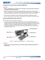
Preparing to Install or Remove Options Modules
CAUTION:
Before removing the instrument from it’s housing, ensure that all power has been
removed from the rear terminals.
1. Remove the instrument from its housing by gripping the side edges of the front panel
(there is a finger grip on each edge) and pull the instrument forwards. This will release the
instrument from the rear connectors in the housing and will give access to the PCBs.
2. Take note of the orientation of the instrument for subsequent replacement into the
housing. The positions of the main and option PCBs in the instrument are shown below.
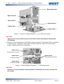
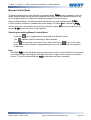
Removing/Replacing Option Modules
With the instrument removed from its housing:
1. To remove or replace modules into Option Slots 1,A or B, it is necessary to gently
separate the CPU and PSU PCBs. This is achieved by detaching the main boards (PSU
and CPU) from the front moulding by lifting first the upper and then lower mounting struts
as shown. This frees the boards from the front. If only Option slots 2 or 3 are to be
changed, this stage is not required as these slots are accessible without separating the
main boards from the front.
Mounting Struts
Option Slot 1
Option Slot A
Option Slot 3
Option Slot 2
Figure 5. Location of Option Modules - 1/16 DIN Instruments
CAUTION:
Take care not to put undue stress on the ribbon cable attaching the display and
CPU boards.
Page 16
Plug-in Options
59305, Issue 6 – March 2006
1
/4 -DIN, 1/8 -DIN & 1/16 - DIN Controllers & Indicators - Product Manual
Mounting Struts
Option Slot B
Option Slot 2
Option Slot A
Option Slot 1
Option Slot 3
Figure 6. Location of Option Modules - 1/8 & 1/4 DIN Instruments
CAUTION:
Take care not to put undue stress on the ribbon cable attaching the display and
CPU boards.
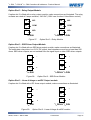
2. Remove or fit the modules into the Option slots as required. The location of the connectors
is shown below. Tongues on each option module locate into a slots cut into the main
boards, opposite each of the connectors.
Option Slot 1
Connectors PL7 & PL8
Option Slot A
Option Slot 2
Connectors PL5 & PL6
Connector PL4A
Option Slot 3
Connector PL4B
Figure 7. Option Module Connectors - 1/16 DIN Instruments
CAUTION:
Check for correct orientation of the modules and that all pins locate correctly into
the socket
59305, Issue 6 – March 2006
Plug-in Options
Page 17
1
/4 -DIN, 1/8 -DIN & 1/16 - DIN Controllers & Indicators - Product Manual
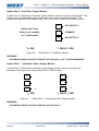
Option Slot B
Connectors PL2A,
PL2B & PL2C
Option Slot 2
Connector PL4A
Option Slot 1
Connectors PL7 & PL8
Option Slot A
Connectors PL5 & PL6
Option Slot 3
Connectors PL4B
Figure 8. Option Module Connectors - 1/8 & 1/4 DIN Instruments
CAUTION:
Check for correct orientation of the modules and that all pins locate correctly into
the socket
Page 18
Plug-in Options
59305, Issue 6 – March 2006
1
/4 -DIN, 1/8 -DIN & 1/16 - DIN Controllers & Indicators - Product Manual
Replacing the Instrument in its Housing
With the required option modules correctly located into their respective positions the
instrument can be replaced into its housing as follows:
1. If required, move the CPU and PSU boards back together, taking care to locate the option
module tongues into the slots in the board opposite. Hold the main boards together whilst
relocating them back into the mounting struts on the front panel.
2. Align the CPU and PSU PCBs with their guides and connectors in the housing.
3. Slowly and firmly, push the instrument in position.
CAUTION:
Ensure that the instrument is correctly orientated. A mechanical stop will operate if
an attempt is made to insert the instrument in the wrong orientation, this stop MUST
NOT be over-ridden.
59305, Issue 6 – March 2006
Plug-in Options
Page 19
1
/4 -DIN, 1/8 -DIN & 1/16 - DIN Controllers & Indicators - Product Manual
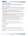
4 Wiring Instructions
Electrical noise is a phenomenon typical of industrial environments. As with any
instrumentation, these guidelines should be followed to minimize the effect of noise.
Installation Considerations
Ignition transformers, arc welders, mechanical contact relays and solenoids are all common
sources of electrical noise in an industrial environment and therefore the following guidelines
MUST be followed.
1. If the instrument is being installed in existing equipment, the wiring in the area should be
checked to ensure that good wiring practices have been followed.
2. Noise-generating devices such as those listed should be mounted in a separate
enclosure. If this is not possible, separate them from the instrument, by the largest
distance possible.
3. If possible, eliminate mechanical contact relays and replace with solid-state relays. If a
mechanical relay being powered by an output of this instrument cannot be replaced, a
solid-state relay can be used to isolate the instrument.
4. A separate isolation transformer to feed only the instrumentation should be considered.
The transformer can isolate the instrument from noise found on the AC power input.
AC Power Wiring - Neutral (for 100 to 240V AC versions)
It is good practice to ensure that the AC neutral is at or near ground (earth) potential. A
proper neutral will help ensure maximum performance from the instrument.
Wire Isolation
Four voltage levels of input and output wiring may be used with the unit:
1. Analogue input or output (for example thermocouple, RTD, VDC, mVDC or mADC)
2. Relays & Triac outputs
3. SSR Driver outputs
4. AC power
CAUTION:
The only wires that should run together are those of the same category.
If any wires need to run parallel with any other lines, maintain a minimum space of 150mm
between them.
If wires MUST cross each other, ensure they do so at 90 degrees to minimise interference.
Page 20
Connections
59305, Issue 6 – March 2006
1
/4 -DIN, 1/8 -DIN & 1/16 - DIN Controllers & Indicators - Product Manual
Use of Shielded Cable
All analogue signals must use shielded cable. This will help eliminate electrical noise
induction on the wires. Connection lead length must be kept as short as possible keeping the
wires protected by the shielding. The shield should be grounded at one end only. The
preferred grounding location is at the sensor, transmitter or transducer.
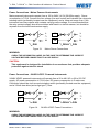
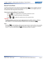
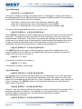
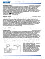
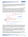
Noise Suppression at Source
Usually when good wiring practices are followed, no further noise protection is necessary.
Sometimes in severe electrical environments, the amount of noise is so great that it has to be
suppressed at source. Many manufacturers of relays, contactors etc supply 'surge
suppressors' which mount on the noise source. For those devices that do not have surge
suppressors supplied, Resistance-Capacitance (RC) networks and/or Metal Oxide Varistors
(MOV) may be added.
Inductive coils:- MOVs are recommended for transient suppression in inductive coils,
connected in parallel and as close as possible to the coil. Additional protection may be
provided by adding an RC network across the MOV.
Figure 9. Transient suppression with inductive coils
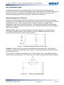
Contacts:- Arcing may occur across contacts when they open and close. This results in
electrical noise as well as damage to the contacts. Connecting a properly sized RC network
can eliminate this arc.
For circuits up to 3 amps, a combination of a 47 ohm resistor and 0.1 microfarad capacitor
(1000 volts) is recommended. For circuits from 3 to 5 amps, connect two of these in parallel.
Figure 10.
59305, Issue 6 – March 2006
Contact noise suppression
Connections
Page 21
1
/4 -DIN, 1/8 -DIN & 1/16 - DIN Controllers & Indicators - Product Manual
Sensor Placement (Thermocouple or RTD)
If the temperature probe is to be subjected to corrosive or abrasive conditions, it must be
protected by an appropriate thermowell. The probe must be positioned to reflect true process
temperature:
1. In a liquid media - the most agitated area
2. In air - the best circulated area
CAUTION:
The placement of probes into pipe work some distance from the heating vessel
leads to transport delay, which results in poor control.
For a two wire RTD a wire link should be used in place of the third wire. Two wire RTDs must
only be used with lead lengths less than 3 metres. Use of three wire RTDs is strongly
recommended.
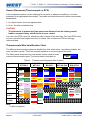
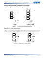
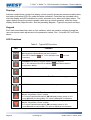
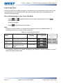
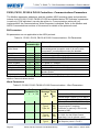
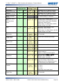
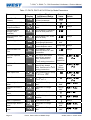
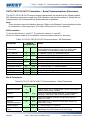
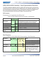
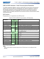
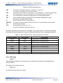
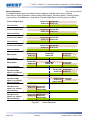
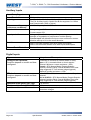
Thermocouple Wire Identification Chart
The different thermocouple types are identified by their wires colour, and where possible, the
outer insulation as well. There are several standards in use throughout the world.
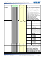
The table below shows the wire and sheath colours used for most
common thermocouple types. The format used in this table is:
+ Wire
- Wire
Sheath
Table 2. Thermocouple Extension Wire Colours
Type
J
T
K
N
B
R&S
C (W5)
International
IEC584-3
+*
Black
-
White
+
Brown
-
White
+
Green
-*
White
+
Pink
-
White
+
Grey
-
White
+
Orange
-
White
USA ANSI
MC 96.1
White
Black
British
BS1843
Yellow
Black
Red
Orange
Pink
Red
Blue
Blue
Red
Yellow
Purple
Green
Green
Orange
Orange
Red
Orange
Blue
Grey
Grey
Brown
Brown
Yellow
Red
Blue
Blue
Blue
Yellow
Brown
Yellow
Red
Red
Black
Blue
Blue
Yellow
Green
Yellow
Black
White
Blue
Red
German
DIN 43710
Black
Blue
Blue
Brown
French
NFC 42-324
Red
Grey
Grey
Red
Grey
Black
Orange
White
Green
Red
+
White
-
Red
Yellow
Green
Blue
Red
Green
Green
White
White
White
Note:
* = Wire is magnetic
Page 22
Connections
59305, Issue 6 – March 2006
1
/4 -DIN, 1/8 -DIN & 1/16 - DIN Controllers & Indicators - Product Manual
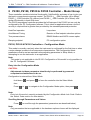
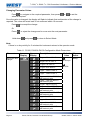
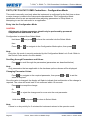
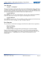
Connections and Wiring
The rear terminal connections for 1/16 DIN and 1/4 & 1/8 DIN instruments are illustrated in the
following diagrams.
In general, all wiring connections are made to the instrument after it is installed. Copper wires
must be used for all connections (except thermocouple signal wires).
WARNING:
TO AVOID ELECTRICAL SHOCK, AC POWER WIRING MUST NOT BE CONNECTED TO THE
SOURCE DISTRIBUTION PANEL UNTIL ALL WIRING PROCEDURES ARE COMPLETED.
WARNING:
CHECK THE INFORMATION LABEL ON THE CASE TO DETERMINE THE CORRECT
VOLTAGE BEFORE CONNECTING TO A LIVE SUPPLY.
Note:
The wiring diagram below shows all possible combinations. The actual connections
required depend upon the features available on the model and the modules and options
fitted.
Figure 11.
59305, Issue 6 – March 2006
Rear terminals (1/16-DIN Instruments)
Connections
Page 23
1
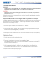
/4 -DIN, 1/8 -DIN & 1/16 - DIN Controllers & Indicators - Product Manual
WARNING:
TO AVOID ELECTRICAL SHOCK, AC POWER WIRING MUST NOT BE CONNECTED TO THE
SOURCE DISTRIBUTION PANEL UNTIL ALL WIRING PROCEDURES ARE COMPLETED.
WARNING:
CHECK THE INFORMATION LABEL ON THE CASE TO DETERMINE THE CORRECT
VOLTAGE BEFORE CONNECTING TO A LIVE SUPPLY.
Note:
The wiring diagram below shows all possible combinations. The actual connections
required depend upon the features available on the model and the modules and options
fitted.
Figure 12.
Page 24
Rear terminals (1/4-DIN & 1/8-DIN Instruments)
Connections
59305, Issue 6 – March 2006
1
/4 -DIN, 1/8 -DIN & 1/16 - DIN Controllers & Indicators - Product Manual
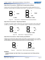
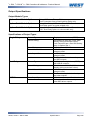
Power Connections - Mains Powered Instruments
Mains powered instruments operate from a 100 to 240V (±10%) 50/60Hz supply. Power
consumption is 7.5VA. Connect the line voltage (live and neutral) as illustrated via a two-pole
isolating switch (preferably located near the equipment) and a 1amp anti-surge fuse. If the
instrument has relay outputs with contacts carrying mains voltage, it is recommended that
the relay contacts supply should be switched and fused in a similar manner, but should be
separate from the instruments mains supply.
9
L
∼
13
∼
10
N
14
N
1
L
1
/4 DIN & 1/8 DIN
/16 DIN
Figure 13.
Mains Power Connections
WARNING:
CHECK THE INFORMATION LABEL ON THE CASE TO DETERMINE THE CORRECT
VOLTAGE BEFORE CONNECTING TO A LIVE SUPPLY.
CAUTION:
This equipment is designed for installation in an enclosure that provides adequate
protection against electric shock
Power Connections - 24/48V AC/DC Powered Instruments
24/48V AD/DC powered instruments will operate from a 20 to 48V AC or 22 to 55V DC
supply. AC power consumption is 7.5VA max, DC power consumption is 5 watts max.
Connection should be via a two-pole isolating switch (preferably located near the equipment)
and a 315mA slow-blow (anti-surge type T) fuse.
9
10
1
/16 DIN
Figure 14.
_
∼
13
+
14
_
∼
+
1
/4 DIN & 1/8 DIN
24/48V AC/DC Power Connections
WARNING:
CHECK THE INFORMATION LABEL ON THE CASE TO DETERMINE THE CORRECT
VOLTAGE BEFORE CONNECTING TO A LIVE SUPPLY.
59305, Issue 6 – March 2006
Connections
Page 25
1
/4 -DIN, 1/8 -DIN & 1/16 - DIN Controllers & Indicators - Product Manual
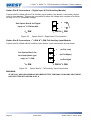
Universal Input Connections - Thermocouple (T/C)
Use only the correct thermocouple wire or compensating cable from the probe to the
instrument terminals avoiding joints in the cable if possible. Failure to use the correct wire
type will lead to inaccurate readings. Ensure correct polarity of the wires by crossreferencing the colours with a thermocouple reference table.
4
_
3
_
5
+
2
+
1
1
/4 DIN & 1/8 DIN
/16 DIN
Figure 15.
Thermocouple Input Connections
Universal Input Connections – PT100 (RTD) input
For three wire RTDs, connect the resistive leg and the common legs of the RTD as
illustrated. For a two wire RTD a wire link should be used in place of the third wire (shown by
dotted line). Two wire RTDs should only be used when the leads are less than 3 metres long.
Avoid cable joints.
4
3
5
2
RTD
RTD
6
1
1
1
/4 DIN & 1/8 DIN
/16 DIN
Figure 16.
RTD Input Connections
Four wire RTDs can be used, provided that the fourth wire is left unconnected. This wire
should be cut short or tied back so that it cannot contact any of the terminals on the rear of
the instrument.
Page 26
Connections
59305, Issue 6 – March 2006
1
/4 -DIN, 1/8 -DIN & 1/16 - DIN Controllers & Indicators - Product Manual
Universal Input Connections - Linear Volt, mV or mA input
Linear DC voltage, millivolt or milliamp input connections are made as illustrated. Carefully
observe the polarity of the connections.
4
_
5
+
+
_
2
+
_
1
mV/V
1
1
/4 DIN & 1/8 DIN
/16 DIN
Figure 17.
_
mA
mV/V
6
3
mA
4
+
DC Volt, mV & mA Input Connections
Option Slot 1 – Relay Output Module
If option slot 1 is fitted with a relay output module, make connections as illustrated. The relay
contacts are rated at 2 amps resistive, 240 VAC (120V max for direct Valve Motor control).
1
N/O
19
N/C
2
COM
20
COM
3
N/C
21
N/O
1
/16 DIN
Figure 18.
59305, Issue 6 – March 2006
1
/4 DIN & 1/8 DIN
Option Slot 1 – Relay Module
Connections
Page 27
1
/4 -DIN, 1/8 -DIN & 1/16 - DIN Controllers & Indicators - Product Manual
Option Slot 1 - SSR Driver Output Module
If option slot 1 is fitted with an SSR driver output module, make connections as illustrated.
The solid-state relay driver is a 0-10V DC signal, load impedance must be no less than 500
ohms. SSR driver outputs are not isolated from the signal input or other SSR driver outputs.
1
20
∼
2
∼
21
1
1
/4 DIN & 1/8 DIN
/16 DIN
Figure 19.
Option Slot 1 - SSR Driver Module
Option Slot 1 - Triac Output Module
If option slot 1 is fitted with a Triac output module, make connections as shown. This output
is rated at 0.01 to 1 amp @ 280V AC 50/60Hz. (140V max for direct Valve Motor control).
1
19
+
_
20
2
21
_
3
1
+
1
/4 DIN & 1/8 DIN
/16 DIN
Figure 20.
Option Slot 1 - Triac Module
Option Slot 1 - Linear Voltage or mADC Output module
If option slot 1 is fitted with a DC linear output module, make connections as illustrated.
1
19
+
20
2
3
21
_
1
Page 28
+
1
/4 DIN & 1/8 DIN
/16 DIN
Figure 21.
_
Option Slot 1 - Linear Voltage & mADC Module
Connections
59305, Issue 6 – March 2006
1
/4 -DIN, 1/8 -DIN & 1/16 - DIN Controllers & Indicators - Product Manual
Option Slot 2 - Relay Output Module
If option slot 2 is fitted with a relay output module, make connections as illustrated. The relay
contacts are rated at 2 amps resistive, 240 VAC (120V max for direct Valve Motor control).
13
N/O
22
N/C
14
COM
23
COM
15
N/C
24
N/O
1
1
/4 DIN & 1/8 DIN
/16 DIN
Figure 22.
Option Slot 2 - Relay Module
Option Slot 2 - SSR Driver Output Module
If option slot 2 is fitted with an SSR driver output module, make connections as illustrated.
The solid-state relay driver is a 0-10V DC signal, load impedance must be no less than 500
ohms. SSR driver outputs are not isolated from the signal input or other SSR driver outputs.
13
22
+
23
14
15
_
24
_
1
+
1
/4 DIN & 1/8 DIN
/16 DIN
Figure 23.
Option Slot 2 - SSR Driver Module
Option Slot 2 - Triac Output Module
If option slot 2 is fitted with a Triac output module, make connections as shown. This output
is rated at 0.01 to 1 amp @ 280V AC 50/60Hz. (140V max for direct Valve Motor control).
13
23
∼
14
1
/16 DIN
Figure 24.
∼
24
1
/4 DIN & 1/8 DIN
Option Slot 2 - Triac Module
WARNING:
THIS MODULE MUST NOT BE FITTED INTO OPTION SLOT 3.
59305, Issue 6 – March 2006
Connections
Page 29
1
/4 -DIN, 1/8 -DIN & 1/16 - DIN Controllers & Indicators - Product Manual
Option Slot 2 - Dual Relay Output Module
If option slot 2 is fitted with a dual relay output module, make connections as illustrated. This
module has two independent relays, which share a common connection terminal. The
contacts are rated at 2 amp resistive 240 VAC. (120V max for direct Valve Motor control).
13
N/O OUTPUT 2
22
N/O OUTPUT 4
14
COMMON
23
COMMON
15
N/O OUTPUT 4
24
N/O OUTPUT 2
1
1
/4 DIN & 1/8 DIN
/16 DIN
Figure 25.
Option Slot 2 - Dual Relay Module
WARNING:
THIS MODULE MUST NOT BE FITTED INTO OPTION SLOT 3 ON 1/16 DIN INSTRUMENTS.
Option Slot 2 - Linear Voltage or mADC Output module
If option slot 2 is fitted with a DC linear output module, make connections as illustrated.
13
22
+
23
14
1
+
1
/4 DIN & 1/8 DIN
/16 DIN
Page 30
24
_
15
Figure 26.
_
Option Slot 2 - Linear Voltage & mADC module
Connections
59305, Issue 6 – March 2006
1
/4 -DIN, 1/8 -DIN & 1/16 - DIN Controllers & Indicators - Product Manual
Option Slot 3 - Relay Output Module
If option slot 3 is fitted with a relay output module, make connections as illustrated. The relay
contacts are rated at 2 amps resistive, 240 VAC (120V max for direct Valve Motor control).
16
N/C
10
N/C
17
COM
11
COM
18
N/O
12
N/O
1
1
/4 DIN & 1/8 DIN
/16 DIN
Figure 27.
Option Slot 3 - Relay Module
Option Slot 3 - SSR Driver Output Module
If option slot 3 is fitted with an SSR driver output module, make connections as illustrated.
The solid-state relay driver is a 0-10V DC signal; load impedance must be no less than 500
ohms. SSR driver outputs are not isolated from the signal input or other SSR driver outputs.
10
_
16
_
11
17
18
12
+
1
+
1
/4 DIN & 1/8 DIN
/16 DIN
Figure 28.
Option Slot 3 - SSR Driver Module
Option Slot 3 - Linear Voltage or mADC Output module
If option slot 3 is fitted with a DC linear output module, make connections as illustrated.
10
_
16
11
17
18
1
59305, Issue 6 – March 2006
12
+
/16 DIN
Figure 29.
_
+
1
/4 DIN & 1/8 DIN
Option Slot 3 - Linear Voltage & mADC module
Connections
Page 31
1
/4 -DIN, 1/8 -DIN & 1/16 - DIN Controllers & Indicators - Product Manual
Option Slot 3 - Dual Relay Output Module
If option slot 3 is fitted with a dual relay output module, make connections as illustrated. This
module has two independent relays, which share a common connection terminal. The
contacts are rated at 2 amp resistive 240 VAC. (120V max for direct Valve Motor control).
10
N/O OUTPUT 3
11
COMMON
12
N/O OUTPUT 5
Option Slot 3 Dual
Relay is not available
on 1/16 DIN models
1
1
/4 DIN & 1/8 DIN
/16 DIN
Figure 30.
Option Slot 3 - Dual Relay Module
WARNING:
THIS MODULE MUST NOT BE FITTED INTO OPTION SLOT 3 ON 1/16 DIN INSTRUMENTS.
Option Slot 3 - Transmitter Power Supply Module
If option slot 3 is fitted with a transmitter power supply module, make connections as
illustrated. The output is an unregulated 24V DC, 22mA supply.
10
_
16
11
17
18
12
+
1
+
1
/4 DIN & 1/8 DIN
/16 DIN
Figure 31.
_
Option Slot 3 - Transmitter Power Supply Module
WARNING:
THIS MODULE MUST NOT BE FITTED INTO OPTION SLOT 2.
Page 32
Connections
59305, Issue 6 – March 2006
1
/4 -DIN, 1/8 -DIN & 1/16 - DIN Controllers & Indicators - Product Manual
Option Slot A Connections - RS485 Serial Communications Module
If option slot A is fitted with the RS485 serial communication module, connections are as
illustrated. Carefully observe the polarity of the A (Rx/Tx +ve) and B (Rx/Tx -ve) connections.
11
16
A
17
B
18
COM
B
RS485
12
RS485
A
1
1
/4 DIN & 1/8 DIN
/16 DIN
Figure 32.
Option Slot A – RS485 Serial Communications Module
Option Slot A Connections - Digital Input Module
If a digital input module is fitted in option slot A, this may be connected to either voltage free
contacts (e.g. switch or relay), or a TTL compatible voltage. Connections are shown below.
11
_
16
+
12
+
17
_
1
1
/4 DIN & 1/8 DIN
/16 DIN
Figure 33.
Option Slot A – Digital Input Module
Option Slot A Connections – Basic Auxiliary Input Module
If option slot A is fitted with a basic auxiliary input module, connect as shown. For 1/4-DIN &
1
/8-DIN models it is recommend that the full auxiliary input (Option Slot B) is used instead, as
this has additional features and leaves option slot A free for other modules.
11
_
16
+
12
+
17
_
1
/16 DIN
Figure 34.
1
/4 DIN & 1/8 DIN
Option Slot A – Basic Auxiliary Input Module
WARNING:
THIS MODULE MUST NOT BE FITTED IF FULL AUXILIARY INPUT IS FITTED IN OPTION
SLOT B.
59305, Issue 6 – March 2006
Connections
Page 33
1
/4 -DIN, 1/8 -DIN & 1/16 - DIN Controllers & Indicators - Product Manual
Option Slot B Connections – Digital Input 2 (Full Auxiliary Module)
If option slot B is fitted with the Full Auxiliary input module (see below), a secondary digital
input is also provided. This may be connected to either the voltage free contacts of a switch
or relay, or a TTL compatible voltage.
See Option Slot A for Digital
Input on 1/16 DIN models
1
+
8
_
1
/4 DIN & 1/8 DIN
/16 DIN
Figure 35.
9
Option Slot B – Digital Input 2 Connections
Option Slot B Connections – 1/4 DIN & 1/8 DIN Full Auxiliary Input Module
If option slot B is fitted with full auxiliary input feature, input connections are as shown.
See Option Slot A for
7
+
(or Pot Low)
6
_
(or Pot Wiper)
Aux input (basic type
only) on 1/16 DIN
1
(or Pot High)
1
/4 DIN & 1/8 DIN
/16 DIN
Figure 36.
5
Option Slot B – Full Auxiliary Input Connections
WARNING:
IF THE FULL AUXILIARY MODULE HAS BEEN FITTED, THE BASIC AUXILIARY INPUT MUST
NOT BE FITTED INTO OPTION SLOT A.
Page 34
Connections
59305, Issue 6 – March 2006
1
/4 -DIN, 1/8 -DIN & 1/16 - DIN Controllers & Indicators - Product Manual
5 Powering Up
WARNING:
ENSURE SAFE WIRING PRACTICES ARE FOLLOWED
The instrument must be powered from a supply according to the wiring label on the side of
the unit. The supply will be either 100 to 240V AC, or 24/48V AC/DC powered. Check
carefully the supply voltage and connections before applying power.
CAUTION:
When powering up for the first time, disconnect the output connections.
Powering Up Procedure
At power up, a self-test procedure is automatically started, during which all LED segments
and indicators are lit. At the first power up from new, or if the option modules are changed,
#/ 3C" will be displayed, indicating configuration is required (refer to section 6). At all
other times, the instrument returns to operator mode once the self-test procedure is
complete.
Overview Of Front Panel
The illustration below shows a typical instrument front panel. Refer to the following table –
Typical LED functions for a description of the front panel indicators. Each model in the range
will vary slightly from the example shown.
Reset or Auto/Manual Select Key
Lower Key
Raise Key
Function Key
Figure 37.
59305, Issue 6 – March 2006
Typical front panel and keys
Powering Up
Page 35
1
/4 -DIN, 1/8 -DIN & 1/16 - DIN Controllers & Indicators - Product Manual
Displays
Indicator models have a single line display, which normally shows the process variable value,
and status indicators LED’s for mode and alarm indication. Controllers are provided with a
dual line display and LED indicators for mode, automatic tune, alarm and output status. The
upper display shows the process variable value during normal operation, whilst the lower
display shows the Setpoint value. See the preceding diagram - Typical front panel and keys.
Keypad
Each instrument has either three or four switches, which are used to navigate through the
user menus and make adjustment to the parameter values. See - Overview Of Front Panel
above
LED Functions
Table 3. Typical LED functions
LED
Function
ON indicates the Setup Mode has been entered
(This LED is labelled
on 1/8 Din indicators and
Controllers)
on Limit
FLASHING indicates the manual mode has been entered
(On 1/8 Din indicators this LED is labelled
and flashes when in
Configuration Mode )
ON indicates that Controller Self Tune mode is engaged
FLASHING indicates that Controller Pre-Tune mode is engaged
FLASHING indicates that an alarm condition is present
FLASHES in unison with Time Proportioning Primary outputs, or turns
ON with Valve Motor “Open” outputs.
For Current Proportioned outputs, ON indicates primary power is >0%
It turns ON when the stored Max. PV value is displayed on indicators
FLASHES in unison with Time Proportioning Secondary outputs, or turns
ON with Valve Motor “Close” outputs.
For Current Proportioned outputs, ON secondary power is >0%
It turns ON when the stored Min. PV value is displayed on indicators
Page 36
Powering Up
59305, Issue 6 – March 2006
1
/4 -DIN, 1/8 -DIN & 1/16 - DIN Controllers & Indicators - Product Manual
6 Messages and Error Indications
The following displays are shown when an error occurs or a hardware change is detected.
Table 4. Error/Faults conditions
Error/Faults Conditions
Configuration & Setup is required.
Seen at first turn on or if hardware
configuration changed.
Press
to enter Configuration
Mode,
next press
or
to enter the
unlock code number,
then press
to proceed.
Upper display
#/
Lower Display
(where fitted)
1
/8 DIN Indicator
Units Display
3C"
3
(#/ for 1
second, then
3C" on
Indicators)
Configuration must be completed
before return to operator mode is
allowed 1
Input more than 5% over-range2
2$$9 *
Normal Display
Normal Display
Input more than 5% under-range3
2''9
*
Normal Display
Normal Display
) ( *
Normal Display
Normal Display
Sensor Break. Break detected in
the input sensor or wiring
Auxiliary input over-range
Normal Display
2$$9 *
n/a
Auxiliary input under-range
Normal Display
2''9
*
n/a
Auxiliary Break. Break detected in
the auxiliary input
Normal Display
) ( *
n/a
Option 1 module fault.
****
@C
Option 2 module fault.
****
@C
Option 3 module fault.
****
@C
Option A module fault.
****
@C
**
@C
* Note
Input sensor and Auxiliary over/under-range or break indications will be seen wherever
these values would normally be displayed.
Option B module fault.
** Note
Option module number follows error legend on 1/16 DIN Indicators (e.g. **)
1
This feature does not guarantee correct configuration. It only helps to ensure that the unit will be configured
before use. Use of set-up mode is not enforced but may be essential for the users application.
2
If the PV display exceeds before 5% over-range is reached, an over-range indication is given.
3
Indicators will allow up to 10% under-range on non-zero based Linear ranges. If the PV display is less than
before the % under-range is reached, an under-range indication is given.
59305, Issue 6 – March 2006
Powering Up
Page 37
1
/4 -DIN, 1/8 -DIN & 1/16 - DIN Controllers & Indicators - Product Manual
7 Instrument Operation Modes
All instruments in the range share a similar user interface. Indicator models (single 4-digit
display) the legend shown in the “Lower Display” column will be shown for approx 1 second
before the “Upper Display” value is shown. For more details, refer to the mode tables below.
Table 5. Model Groups
Model Group
Description
P6100, P6120,
Process
P8100 & P4100 Controllers
Model Group
P6170, P8170 &
P4170
Description
Valve Motor
Controllers
P6010 & P8010
P4700, P6700 &,
P8700
Limit Controllers
Indicators
Select Mode
This mode is used to gain entry to each of the modes available in the instrument.
Entry into the Select Mode
Hold down
and press
in any mode to force the unit to enter Select Mode.
Navigating in Select Mode
Once in Select Mode, press
or
to select the required mode,
then press
to enter the chosen mode.
To prevent unauthorised entry to Configuration, Setup and Automatic Tuning modes, an
unlock code is required. These are shown in the - Lock code values table.
Table 6. Select Mode Menus
Mode
Description
Operator
Mode
Set Up Mode
The Default Mode on power up
used for normal operation.
Used to tailor the instrument to
the application, adjustment of
tuning terms etc.
Used to configure the
instrument for first time use or
on re-installation.
Used to check the hardware,
firmware and manufacturing
information of the instrument.
Used to invoke pre-tune or
self-tune on controllers
Configuration
Mode
Product
Information
Mode
Automatic
Tune Mode
Upper/Main
Display
Lower
Display (or
1st Legend)*
1
/8 DIN
Indicator
Units Display
@/+
-'3/
-
-!/@
-'3/
-
3C"
-'3/
-
C"
-'3/
-
/1C
-'3/
-
*Note:
On Indicators, this legend is shown for approx 1 second before the Main display value.
Page 38
Operating and Information Modes
59305, Issue 6 – March 2006
1
/4 -DIN, 1/8 -DIN & 1/16 - DIN Controllers & Indicators - Product Manual
Unlock Codes
The 0'N screen is seen before entry is allowed to Configuration, Setup and Automatic
Tuning modes.
An unlock code must be correctly selected using the
or
keys to enter the required
mode. An incorrect entry results in a return to Select Mode. The value of the lock codes only
can be changed from within the modes that they apply to.
Table 7.
Description
Lock Code – Entry and Default Values
Upper/Main
Display
Default values are:
Automatic Tune Mode = Set-up mode = Configuration Mode = .
Lower Display
(or 1st Legend)*
1
/8 DIN Indicator
Units Display
0'N
3
*Note:
On Indicators (single line display), this legend is shown for approx 1 second before the
Main display value.
Automatic Tune Mode
Automatic Tune Mode is selected when it is desired to use the Pre-tune and Self-tune
facilities on a controller to assist the user in setting up Proportional band, Integral and
Derivative parameter values. Refer to the following Automatic Tune Mode table.
Pre-tune can be used to set Controller PID parameters approximately. Self-tune may then be
used to optimise the tuning. Pre-tune can be set to run automatically after every power-up
using the Auto Pre-Tune @/ parameter in Setup Mode.
The AT indicator will flash
while pre-tune is operating, and is continuously on
whilst Self-tune is operating. If both Pre-tune and Self-tune are engaged the AT indicator will
flash until Pre-tune is finished, and is then continuously on.
Navigating in Automatic Tune Mode
Press
to select the next parameter in the table and
required.
Hold down
and press
or
to set the value
to return to Select Mode.
Note:
If there is no key activity for 2 minutes the controller automatically returns to operator
mode
59305, Issue 6 – March 2006
Operating and Information Modes
Page 39
1
/4 -DIN, 1/8 -DIN & 1/16 - DIN Controllers & Indicators - Product Manual
Table 8. Automatic Tune Mode Parameters
Parameter
Upper Display
Adjustment Range
Pre-tune
C or "".
Indication remains "" if Pre-Tune
cannot be used at this time. This
applies if:
a). The setpoint is ramping
b). The process variable is less than
5% of span from the setpoint
c). The primary or secondary output
proportional bands = 0
)/1C
""
Controller
models only
Self-tune
C or "".
Indication remains "" if Self-Tune
cannot be used at this time. This
applies if either proportional band = 0.
0 to 9999
-/1C
""
Controller
models only
/'N
Controller
models only
Automatic tune
mode lock code
Lower
Display
Default
Value
When
Visible
Product Information Mode
This is a read only mode describing the instrument and the options fitted to it.
Navigating in the Product Information Mode
Press
to view each parameter in turn.
Hold Down
and press
to return to Select Mode.
Note:
If there is no key activity for 2 minutes the controller automatically returns to operator
mode
Table 9. Product Information Mode Parameters
Possible Values
Input type
Universal input
0C
%C:
/
Option 1
module type
No option fitted
CC )C
Page 40
Upper/Main
Display
Relay
+'5
SSR drive
--+
Triac
/+
Linear voltage / current output
'C
Operating and Information Modes
Lower
Display (or
1st Legend)*
1
Parameter
/8 DIN
Indicator Units
Display
59305, Issue 6 – March 2006
1
/4 -DIN, 1/8 -DIN & 1/16 - DIN Controllers & Indicators - Product Manual
Parameter
Possible Values
Option 2
module type
No option fitted.
Option 3
module type
Auxiliary
option A
module type
Auxiliary
option B
module type
Upper/Main
Display
CC Lower
Display (or
1st Legend)*
1
/8 DIN
Indicator Units
Display
)C
)C
)C
+'5
Relay
Dual relay
=+'5
SSR drive
--+
Triac
/+
Linear voltage / current output
'C
No option fitted.
CC Relay
=+'5
Dual relay
+'5
SSR drive
--+
Linear voltage / current output
'C
24V Transmitter power supply
=N
No option fitted
CC!
RS485 comms
+
Digital input
=#
Basic Auxiliary input
*-)
No option fitted
CC!
)C
Not Applicable
Firmware
Full Auxiliary input and
*-)
digital input 2
Value displayed is firmware type number
"<&
"
Issue No.
Value displayed is firmware issue number
%,,
C
Product Rev
Level
Value displayed is Product Revision Level.
)*'
+
=Mm
=
-C
-C
-C
N
Manufacturing date code (mmyy)
Date of
manufacture
First four digits of serial number
Serial
number 1
Second four digits of serial number
Serial
number 2
Last four digits of serial number
Serial
number 3
*Note:
On Indicators (which have a single line display), this legend is shown for approx 1 second
before the Main display value.
59305, Issue 6 – March 2006
Operating and Information Modes
Page 41
1
/4 -DIN, 1/8 -DIN & 1/16 - DIN Controllers & Indicators - Product Manual
Lock Code View
In the event that a lock code is forgotten, the instrument lock code values can be seen in the
lock code view. In this view the codes are read only, the codes can be changed from the
mode to which they apply.
Entry and Navigating in Lock Code View Mode
together whilst the instrument is powering up until the 3'N
Press
and
display is shown.
Once in this mode
Press
to step between lock codes.
Note:
If there is no key activity for 2 minutes the instrument returns to Operator Mode. To
forcefully exit this view, switch off the instrument.
Table 10. Lock Code View Menu
1
/8 DIN
Lower Display
(or 1st Legend)* Indicator Units
Display
Lock Code
Name
Description
Upper/Main
Display
Configuration
Lock Code
Setup Lock
Code
Automatic
Tune Lock
Code
Read only view of
Configuration Lock Code.
Read only view of Setup
Mode Lock Code.
Read only view of
Automatic Tune Lock
Code.
Current Value
3'N
3
Current Value
-'N
-
Current Value
.'N
*Note:
On Indicators (which have a single line display), this legend is shown for approx 1 second
before the Main display value.
Page 42
Operating and Information Modes
59305, Issue 6 – March 2006
1
/4 -DIN, 1/8 -DIN & 1/16 - DIN Controllers & Indicators - Product Manual
8 P6100, P6120, P8100 & P4100 Controller – Model Group
These controllers combine technical functionality, field flexibility and ease of use to give you
the best in comprehensive process control. The P6100 1/16 –DIN Controller (48 x 48mm),
P8100 1/8 –DIN Controller (96 x 48mm) and P4100 1/4 –DIN Controller (96 x 96mm) offer
similar functionality in three DIN sizes.
The P6120 tamperproof controller provides the full features of the P6100, but can only be
configured by the PC Configurator software. This is ideal for applications where a level of
security is required that is greater than provided by the standard password protection.
Heat/Cool operation
Loop alarm
Auto/Manual Tuning
Remote or Dual setpoint selection options
Two process alarms
RS485 Modbus and ASCII comms option
Ramping setpoint
PC configuration option
P6100, P8100 & P4100 Controllers - Configuration Mode
This mode is normally used only when the instrument is configured for the first time or when
a major change is made to the instruments characteristics. The Configuration Mode
parameters must be set as required before adjusting parameters in Setup Mode, or
attempting to use the instrument in an application.
Note:
This mode is not applicable to the P6120. Configuration of this model is only possible via
the PC Configurator Software.
Entry into the Configuration Mode
CAUTION:
Adjustments to these parameters should only be performed by personnel
competent and authorised to do so.
Configuration is entered from Select Mode
Hold down
and press
to force the controller into the Select Mode.
then
Press
or
to navigate to the Configuration Mode option, then press
.
Note:
Entry into this mode is security-protected by the Configuration Mode Lock Code. Refer to
the Unlock Code section for more details.
Scrolling through Parameters and Values
Press
to scroll through the parameters (parameters are described below).
Note:
Only parameters that are applicable to the hardware options chosen will be displayed.
59305, Issue 6 – March 2006
P6100, P6120, P8100 & P4100 Model Group
Page 43
1
/4 -DIN, 1/8 -DIN & 1/16 - DIN Controllers & Indicators - Product Manual
Changing Parameter Values
Press
to navigate to the required parameter, then press
value as required.
or
to set the
Once the value is changed, the display will flash to indicate that confirmation of the change is
required. The value will revert back if not confirmed within 10 seconds.
Press
to accept the change.
Or
Press
to reject the change and to move onto the next parameter.
Hold down
and press
to return to Select Mode.
Note:
If there is no key activity for 2 minutes the instrument returns to the operator mode.
Table 11. P6100, P8100 & P4100 Configuration Mode Parameters
Parameter
Input type and
Range
Lower
Display
%C)/
Upper
Display
3
B type: 100 to 1824 ºC
"
B type: 211 to 3315 ºF
33
C type: 0 to 2320 ºC
3"
C type: 32 to 4208 ºF
&3
J type: -200 to 1200 ºC
&"
J type: -328 to 2192 ºF
6. 3
J type: -128.8 to 537.7 ºC
with decimal point
J type: -199.9 to 999.9 ºF
with decimal point
K type: -240 to 1373 ºC
6. "
K3
K"
'3
'"
L type: 32 to 1403 ºF
'. 3
L type: 0.0 to 537.7 ºC
with decimal point
L type: 32.0 to 999.9 ºF
with decimal point
K. "
'. "
Default
Value
When
Visible
63
for Europe
Always
6"
for USA
K type: -400 to 2503 ºF
K type: -128.8 to 537.7 ºC
with decimal point
K type: -199.9 to 999.9 ºF
with decimal point
L type: 0 to 762 ºC
k. 3
Page 44
Description
P6100, P6120, P8100 & P4100 Model Group
59305, Issue 6 – March 2006
1
/4 -DIN, 1/8 -DIN & 1/16 - DIN Controllers & Indicators - Product Manual
Parameter
Input type and
Range
(continued)
Lower
Display
Upper
Display
Description
(3
N type: 0 to 1399 ºC
("
N type: 32 to 2551 ºF
+3
R type: 0 to 1759 ºC
+"
R type: 32 to 3198 ºF
-3
S type: 0 to 1762 ºC
-"
S type: 32 to 3204 ºF
/3
T type: -240 to 400 ºC
/"
T type: -400 to 752 ºF
T type: -128.8 to 400.0 ºC
with decimal point
T type: -199.9 to 752.0 ºF
/. "
with decimal point
)3 PtRh20% vs PtRh40%:
0 to 1850 ºC
)" PtRh20% vs PtRh40%:
32 to 3362 ºF
).3 Pt100: -199 to 800 ºC
)/" Pt100: -328 to 1472 ºF
Default
Value
When
Visible
63
for Europe
Always
6"
for USA
/. 3
Input type and
Range
(Continued)
%C)/
)/. 3
)/. "
:
Pt100: -128.8 to 537.7 ºC
with decimal point
Pt100: -199.9 to 999.9 ºF
with decimal point
0 to 20mA DC
63
for Europe
Always
6"
for USA
: 4 to 20mA DC
: 0 to 50mV DC
. 10 to 50mV DC
:
0 to 5V DC
:
1 to 5V DC
: 0 to 10V DC
: 2 to 10V DC
Scale Range
Upper Limit
+1'
Scale Range Lower Limit +100 to Range
Max
Scale Range
Lower Limit
+''
Range Min. to Scale range Upper Limit 100
59305, Issue 6 – March 2006
Linear
inputs =
1000
(°C/°F
inputs =
max
range)
Linear = 0
(°C/°F =
min range)
P6100, P6120, P8100 & P4100 Model Group
Always
Always
Page 45
1
/4 -DIN, 1/8 -DIN & 1/16 - DIN Controllers & Indicators - Product Manual
Parameter
Lower
Display
Decimal point
position
=)-
Control Type
3.4)
Primary Output
Control Action
3.*'
Alarm 1Type
'
Upper
Display
Description
Decimal point position in
non-temperature ranges.
0 = XXXX
1 = XXX.X
2 = XX.XX
3 = X.XXX
-C#'
Primary control =1'
Primary and Secondary
control (e.g. for heat & cool)
+!1
Reverse Acting
=+
Direct Acting
):$
Process High Alarm
):'
Process Low Alarm
= Default
Value
When
Visible
%C@.=
mV, V or
mA
-C#'
Always
+!1
Always
):$
Always
Deviation Alarm
C= Band Alarm
CC No alarm
Process High
Alarm 1 value*
)? Range Min. to Range Max.
Parameter repeated in Setup Mode
Range
Max.
'=
):$
Process Low
Alarm 1 value*
)' Range Min. to Range Max
Parameter repeated in Setup Mode
Range
Min.
'=
):'
Deviation
Alarm 1 Value*
=' ±span from setpoint
Parameter repeated in Setup Mode
'=
= Band Alarm 1
value*
'
Alarm 1
Hysteresis*
Alarm 2 Type
$4 1 LSD to 100% of span (in display units)
on “safe” side of alarm point.
Parameter repeated in Setup Mode
' As for alarm 1 type
'=
C=
Always
):'
Always
Process High
Alarm 2 value*
)? Range Min. to Range Max.
Parameter repeated in Setup Mode
Range
Max.
'=
):$
Process Low
Alarm 2 value*
)' Range Min. to Range Max.
Parameter repeated in Setup Mode
Range
Min.
'=
):'
Deviation
Alarm 2 Value*
=' ±span from setpoint.
Parameter repeated in Setup Mode
'=
= Band Alarm 2
value*
'
Alarm 2
Hysteresis*
$4 1 LSD to 100% of span (in display units)
on “safe” side of alarm point.
Parameter repeated in Setup Mode
'=
C=
Always
Loop Alarm
Enable
' C
Page 46
1 LSD to full span from setpoint.
Parameter repeated in Setup Mode
1 LSD to full span from setpoint.
Parameter repeated in Setup Mode
=, (disabled) or
=, Always
C (enabled)
P6100, P6120, P8100 & P4100 Model Group
59305, Issue 6 – March 2006
1
/4 -DIN, 1/8 -DIN & 1/16 - DIN Controllers & Indicators - Product Manual
Parameter
Lower
Display
Loop Alarm
Time*
'.
Alarm Inhibit
%C?
Upper
Display
Description
1 sec to 99 mins. 59secs
Only applies if primary proportional
band = 0
CC!
No alarms Inhibited
Default
Value
When
Visible
. ' C=
C
CC!
Always
' Alarm 1 inhibited
' Alarm 2 inhibited
/?
Output 1
Usage
Linear Output
1 Range
0- /4)
Alarm 1 and alarm 2
inhibited
)+
Primary Power
-!N
Secondary Power
)+
@C
is not
CC!
7:= Alarm 1, Direct Acting
:+ Alarm 1, Reverse Acting
Not linear
:= Alarm 2, Direct Acting
:+ Alarm 2, Reverse Acting
Not linear
'):=
Loop Alarm, Direct Acting
Not linear
'):+
Loop Alarm, Reverse Acting
Not linear
+:=
Logical Alarm 1 OR Alarm 2
Direct Acting
Not linear
+:+
Logical Alarm 1 OR Alarm 2
Reverse Acting
Not linear
+:=
Logical Alarm 1 AND Alarm
2, Direct Acting
Not linear
+:+
Logical Alarm 1 AND Alarm
2, Reverse Acting
Not linear
+!/-
Retransmit SP Output
Linear only
+!/)
Retransmit PV Output
Linear only
:
0 to 5 V DC output 1
: 0 to 10 V DC output
: 2 to 10 V DC output
Not linear
Not linear
: @C=
'C
: 0 to 20 mA DC output
: 4 to 20 mA DC output
Retransmit
Output 1 Scale
maximum
+$ to Display value at which output will be
maximum
Range
max
0,!=
+!/- or
+!/)
Retransmit
Output 1 Scale
minimum
+'
Range min
0,!=
+!/- or
+!/)
59305, Issue 6 – March 2006
to Display value at which output will be
minimum
P6100, P6120, P8100 & P4100 Model Group
Page 47
1
/4 -DIN, 1/8 -DIN & 1/16 - DIN Controllers & Indicators - Product Manual
Parameter
Output 2
Usage
Lower
Display
Upper
Display
Description
0- As for output 1
Default When
Value
Visible
-!N if dual @C
control
selected
else :=
Linear Output
2 Range
/4) As for output 1
Retransmit
Output 2 Scale
maximum
+$ to Display value at which output will be
maximum
Retransmit
Output 2 Scale
minimum
+'
Output 3
Usage
0- As for output 1
to Display value at which output will be
minimum
is not
CC!
: @C=
'C
Range
0,!=
max
+!/- or
+!/)
Range min 0,!=
+!/- or
+!/)
7:= @C
is not
CC!
Linear Output
3 Range
/4) As for output 1
Retransmit
Output 3 Scale
maximum
+$ to Display value at which output will be
maximum
Retransmit
Output 3 Scale
minimum
+'
Display
Strategy
=,@ ,,,, or (see Operator Mode)
)+/
-3% ASCII
Comms
Protocol
Bit rate
Communications Address
Page 48
to Display value at which output will be
minimum
MmC Modbus with no parity
Mm Modbus with Even Parity
1=
==+
Mm Modbus with Odd Parity
. 1.2 kbps
.
2.4 kbps
.
4.8 kbps
.
9.6 kbps
.
19.2 kbps
Unique address assigned to
the instrument in the range
of 1 to 255 (Modbus),
1 to 99 (Ascii)
P6100, P6120, P8100 & P4100 Model Group
: @C=
'C
Range
0,!=
max
+!/- or
+!/)
Range min 0,!=
+!/- or
+!/)
Always
MmC @C=
+
.
@C=
+
@C=
+
59305, Issue 6 – March 2006
1
/4 -DIN, 1/8 -DIN & 1/16 - DIN Controllers & Indicators - Product Manual
Parameter
Lower
Display
Communications Write
Enable
3 C
Digital Input 1
Usage
=#
Digital Input 2
Usage
Remote
Setpoint Input
Range
=#
+C)
Upper
Display
Description
r_o
Read only. Comms
writes ignored
r_Ww
Read / Write. Writing via
Comms is possible
=-
Setpoint 1 / Setpoint 2
Select**
=,
Automatic / Manual
Select**
=-
Setpoint 1 / Setpoint 2
Select**
=,
Automatic / Manual
Select**
=+,
Remote / Local Setpoint
Select
:
0 to 20mA DC input
:
4 to 20mA DC input
:
0 to 10V DC input
:
2 to 10V DC input
:
0 to 5V DC input
:
1 to 5V DC input
0 to 100mV DC input
)/
Potentiometer (≥2KΩ)
Default
Value
When
Visible
r_ Ww
Always
=- @C=
=#
=+-
@C=
+-)
: @C or
@C=
+-)
@C=
+-)
Remote
Setpoint Upper
Limit
+-)1
to RSP value to be used when RSP input is
at maximum.
Range
max
@C=
+-)
Remote
Setpoint Lower
Limit
+-)'
Range min
@C=
+-)
Remote
Setpoint Offset
+-)
to RSP value to be used when RSP input is
at minimum.
Offset applied to RSP value. Constrained
within Scale Range Upper Limit and
Scale Range Lower Limit.
Configura-
3'N
to @C=
+-)
Always
tion Mode Lock
Code
*Note:
Alarm parameters marked * are repeated in Setup Mode.
**Note:
If =# or =# = =- the remote setpoint input feature is disabled. The instrument
uses the two internal setpoints (SP1 & SP2) instead.
If =# and =# are set to the same value, the status of digital input 2 will take
precedence over digital input 1.
59305, Issue 6 – March 2006
P6100, P6120, P8100 & P4100 Model Group
Page 49
1
/4 -DIN, 1/8 -DIN & 1/16 - DIN Controllers & Indicators - Product Manual
P6100, P6120, P8100 & P4100 – Setup Mode
This mode is normally selected only after Configuration Mode has been completed, and is
used when a change to the process set up is required. It can affect the range of adjustments
available in Operator Mode. Using the PC Configurator software, it is possible to configure an
Extended Operator Mode. Setup Mode parameters are moved into Operator Mode, and
these parameters appear after the normal Operator Mode screen sequence has been
completed.
Note:
This mode is not applicable to the P6120. Setup of this model is only possible via the PC
Configurator Software.
Note:
Entry into Setup Mode is security-protected by the Setup Mode lock code.
Entry into the Setup Mode
Hold down
and press
Press
or
Setup Mode.
to enter the Select Mode
to navigate to the Setup Mode option, then press
to enter
Scrolling through Parameters & Values
Press
to scroll through the parameters (refer to the table below) and their values.
Changing Parameter Values
Press
to select the required parameter, then press
required.
or
to set the value as
Once the displayed value is changed the effect is immediate. No confirmation of the
change is required.
Note:
If there is no key activity for two minutes the instrument returns to the operator mode.
Page 50
P6100, P6120, P8100 & P4100 Model Group
59305, Issue 6 – March 2006
1
/4 -DIN, 1/8 -DIN & 1/16 - DIN Controllers & Indicators - Product Manual
Table 12. P6100, P8100 & P4100 Set Up Mode Parameters
Parameter
Lower
Display
Upper Display
Adjustment Range
Default
Value
When
Visible
Input Filter Time
constant
"'/
OFF, 0.5 to 100.0 secs in
0.5 sec increments
Process Variable Offset
""-
±Span of controller
Primary Power
))Ww
The current Primary
Output Power. Read Only.
N/A
Always
Secondary Power
-)Ww
The current Secondary
Output power. Read Only.
N/A
3/5@ = =1'
Primary Output
Proportional Band
):)
0.0% (ON/OFF control)
and 0.5% to 999.9% of
input span.
.
Always
Secondary Output
Proportional Band
):-
0.0% (ON/OFF control)
and 0.5% to 999.9% of
input span.
.
3/5@ = =1'
Automatic Reset
(Integral Time
Constant)
+,/
0.01 to 99.59 (1 sec to 99
mins 59 secs) and OFF
.
):)
is not .
Rate (Derivative Time
Constant)
+. 0.00 to 99.59 (OFF to 99
mins 59 secs)
.
):)
is not .
'
-20% to +20% of the sum
of the Primary and
Secondary Proportional
Bands
):)
is not .
Overlap/Deadband
.
Always
Always
Manual Reset (Bias)
- 0% to 100% (-100% to
100% if 3/5@ = =1')
):)
is not .
Primary Output
ON/OFF Differential
=") 0.1% to 10.0% of input
span (enter in % span)
="- 0.1% to 10.0% of input
span (enter in % span)
="" 0.1% to 10.0% of input
span (enter in % span)
.
):)= .
.
):- = .
.
):) and ):-
Secondary Output
ON/OFF Differential
Primary and Secondary
Output ON/OFF
Differential
Setpoint Upper Limit
= . -)1'
Current Setpoint value to
Scale Range Maximum
Range
Max.
Always
Setpoint Lower limit
-)''
Scale Range Minimum to
current Setpoint value
Range Min
Always
Primary (Heat) Output
Upper Power Limit
)1'
0% to 100% of full power
):)
is not .
3.
0.5, 1, 2, 4, 8, 16, 32, 64,
128, 256 or 512 secs.
Not applicable to linear
outputs
0- = )+
or -!N
Output 1
Cycle Time
or 1,
59305, Issue 6 – March 2006
P6100, P6120, P8100 & P4100 Model Group
Page 51
1
/4 -DIN, 1/8 -DIN & 1/16 - DIN Controllers & Indicators - Product Manual
Parameter
Lower
Display
Upper Display
Adjustment Range
Default
Value
Output 2
Cycle Time
3.
0.5, 1, 2, 4, 8, 16, 32, 64,
128, 256 or 512 secs.
Not applicable to linear
outputs
Output 3
Cycle Time
3.
0.5, 1, 2, 4, 8, 16, 32, 64,
128, 256 or 512 secs.
Not applicable to linear
outputs
When
Visible
0- = )+
or -!N
or 1,
0- = )+
or -!N
or 1,
Process High Alarm 1
value*
)? Range Min. to Range
Max.
Range
Max.
' = ):$
Process Low Alarm 1
value*
)'
Range Min. to Range
Max.
Range
Min.
' = ):'
Deviation Alarm 1
Value*
='
±span from setpoint
' = = Band Alarm 1 value*
'
1 LSD to full span from
setpoint.
' = C=
Alarm 1 Hysteresis*
$4 Up to 100% of span
)? Range Min. to Range
Max.
Always
Process High Alarm 2
value*
Range
Max.
' = ):$
Range
Min.
' = ):'
Process Low Alarm 2
value*
)'
Range Min. to Range
Max.
Deviation Alarm 2
Value
='
±span from setpoint
' = = Band Alarm 2 value*
'
1 LSD to full span from
setpoint.
' = C=
Alarm 2 Hysteresis*
$4 Up to 100% of span
'. 1 sec to 99 mins. 59secs.
Only applies if primary
proportional band = 0
Always
Loop Alarm Time*
Auto Pre-tune enable /
disable
).
Manual Control select
enable / disable
) C
Setpoint Select shown
in Operator Mode,
enable / disable
-- C
Setpoint ramp shown in
operator mode, enable /
disable
SP Ramp Rate Value
Page 52
=-disabled or
' C = C
=- Always
C enabled
=-disabled or
=- Always
C enabled
=-disabled or
C enabled
-@+
=-disabled or
=- Slot A or B fitted
with RSP module
=- Always
C enabled
+)
1 to 9999 units/hour or Off
(blank)
P6100, P6120, P8100 & P4100 Model Group
Blank
Always
59305, Issue 6 – March 2006
1
/4 -DIN, 1/8 -DIN & 1/16 - DIN Controllers & Indicators - Product Manual
Parameter
Setpoint Value
Local Setpoint Value
Setpoint 1 Value
Setpoint2 Value
Lower
Display
-)
'-)
:'-)
or
*'-)
-)
:-)
or
*-)
-)
:-)
or
*-)
Upper Display
Adjustment Range
Default
Value
Range
minimum
Always
Range
minimum.
: or * before the legend
indicates if this is the
currently active SP
Within scale range upper
and lower limits.
@C or
@C = +-)
Range
minimum.
: or * before the legend
indicates if this is the
currently active SP
Within scale range upper
and lower limits.
=# or
=# = =-
Range
minimum.
=# or
=# = =-
Within scale range upper
and lower limits
Within scale range upper
and lower limits.
: or * before the legend
indicates if this is the
currently active SP
0 to 9999
-'N
**First Operator mode displays follows.
Note:
Alarm parameters marked * are repeated in Configuration Mode.
Set-up Lock Code
When
Visible
Always
Note:
**Once the complete list of Set Up Mode parameters has been displayed, the first
Operator Mode display is shown without exiting from Set Up Mode. Display seen is
dependant on the Display Strategy and status of Auto/Manual mode selection.
59305, Issue 6 – March 2006
P6100, P6120, P8100 & P4100 Model Group
Page 53
1
/4 -DIN, 1/8 -DIN & 1/16 - DIN Controllers & Indicators - Product Manual
P6100, P8100 & P4100 Controllers - Operator Mode
This is the mode used during normal operation of the instrument. It can be accessed from
Select Mode, and is the usual mode entered at power-up. The available displays are
dependent upon whether Dual or Remote Setpoint modes are being used, whether Setpoint
Ramping is enabled and the setting of the Display Strategy parameter in Configuration Mode.
Note:
For model P6120 only the Initial Operator Mode screen is available.
WARNING:
IN NORMAL OPERATION, THE OPERATOR MUST NOT REMOVE THE CONTROLLER FROM
ITS HOUSING OR HAVE UNRESTRICTED ACCESS TO THE REAR TERMINALS, AS THIS
WOULD PROVIDE POTENTIAL CONTACT WITH HAZARDOUS LIVE PARTS.
CAUTION:
Set all Configuration Mode parameters and Set Up Mode parameters as required
before starting normal operations.
P6100, P8100 & P4100 Controllers – Extended Operator Mode
Using the PC configuration software, it is possible to extend the Operator Mode displays
available by adding parameters from Setup Mode. When an extended Operator Mode is
configured the additional parameters are available after the standard operator displays.
Note:
This mode is not applicable to the P6120.
Navigating in Operator Mode
Press
to move between displays.
When a display value can be adjusted, use
or
to change its value.
Note:
The operator can freely view the parameters in this mode, but alteration depends on the
settings in the Configuration and Set Up Modes. All parameters in Display strategy 6 are
read only, and can only be adjusted via Setup mode.
Page 54
P6100, P6120, P8100 & P4100 Model Group
59305, Issue 6 – March 2006
1
/4 -DIN, 1/8 -DIN & 1/16 - DIN Controllers & Indicators - Product Manual
Table 13. P6100, P8100 & P4100 Operator Mode Displays
Upper
Display
Lower
Display
When Visible
Description
PV Value
Active SP
Value
Display strategy 1
and 2.
(Initial Screen)
Process Variable and target value of
currently selected Setpoint.
Local SP is adjustable in Strategy 2
PV Value
Actual SP
Value
Display strategy 3
and 6
(Initial Screen)
Process Variable and actual value of
selected Setpoint (e.g. ramping SP value).
Read only
PV Value
Blank
Display strategy 4.
(Initial Screen)
Shows Process Variable.
Read only
Actual SP
Value
Blank
Display strategy 5.
(Initial Screen)
Shows target value of currently selected
Setpoint. Read only
Target value of Setpoint.
Adjustable except in Strategy 6
SP Value
-)
SP1 Value
-)
or
:-)
Display strategy 1, 3,
4, 5 and 6 if Digital
Input is not =-7 in
config mode and
RSP is not fitted
If Digital Input is set
for dual SP (=-7 in
config mode).
SP2 Value
-)
or
:-)
If Digital Input is set
for dual SP (=-7 in
config mode).
Target value of Setpoint 2. :-) means
SP2 is selected as the active Setpoint.
Adjustable except in Strategy 6
Local Setpoint
Value
'-)
:'-)
If Remote Setpoint
Input is fitted and
Digital Input is not
=-7 in config
mode
Target value of Local Setpoint. :'-)
means the local setpoint is selected as the
active SP (if the digital input has been
If Remote Setpoint
Input is fitted and
Digital Input is not
=-7 in config
mode
Target value of Remote Setpoint. :+-)
means the remote setpoint is selected as
the active SP (if the digital input has been
or
*'-)
Remote
Setpoint
Value
_'-)
+-)
or
=#
+-)
:+-)
or
*+-)
-)-
Actual SP
Value
-)+)
SP Ramp
Rate Value
+)
59305, Issue 6 – March 2006
If Remote Setpoint
Input is fitted, Digital
Input is not =-7 in
config mode and
-- C is enabled in
Setup mode
If a Ramping
Setpoint is in use
(+) not Blank).
If -@+ (ramping SP)
is enabled in Setup
mode.
Target value of Setpoint 1. :-) means
SP1 is selected as the active Setpoint.
Adjustable except in Strategy 6
overridden, the _* character is lit instead).
Adjustable except in Strategy 6
overridden, the _* character is lit instead).
Read only
Setpoint Select. Selects between Local or
Remote Setpoints.
'-) = local SP, +-) = remote SP, =#
= selection via digital input (if configured).
Note: '-) or +-) will override the digital
input (active SP indication changes to *)
Adjustable except in Strategy 6
Actual value of selected Setpoint (e.g.
ramping SP value). Read only
Setpoint ramping rate, in units per hour.
Set to Blank (higher than ) to turn off
ramping. Adjustable except in Strategy 6
P6100, P6120, P8100 & P4100 Model Group
Page 55
1
/4 -DIN, 1/8 -DIN & 1/16 - DIN Controllers & Indicators - Product Manual
Upper
Display
Lower
Display
'-/
Active Alarm
Status
When Visible
When any alarm is
active.
ALM indicator
will also flash
Description
Upper display shows which alarm(s) are
active. Inactive alarms are blank
Alarm 1 Active
Alarm 2 Active
'
Loop Alarm Active
Note:
When an extended Operator Mode is configured the additional parameters are available
after the above parameters. Extended Operator Mode parameters can only be configured
using the PC software.
Note:
For model P6120, only the Initial Operator Mode screen is available. If Display Strategy 2
has been configured from via the PC Configurator software, the selected target Setpoint
can adjusted by use of the
and
keys. All other Operator Mode menu functions are
disabled.
Adjusting the Local Setpoint(s)
Setpoints can be adjusted within the limits set by the Setpoint Upper and Lower Limit
parameters in Setup. Operator Mode adjustment of Setpoint is not possible if Display
Strategy 6 has been selected on Configuration Mode.
Press
to select the adjustable setpoint display
Press
or
to adjust the setpoint to the required value.
Adjusting the Setpoint Ramp Rate
The ramp rate may be adjusted in the range 1 to 9999 and OFF. Increasing the ramp rate
value beyond 9999 will cause the upper display to go blank and setpoint ramping to be
switched OFF. Setpoint ramping can be resumed by decreasing the ramp rate to 9999 or
less.
Press
to select the adjustable setpoint display
Press
or
to adjust the setpoint to the required value.
WARNING:
THE SETPOINT RAMP FEATURE DISABLES THE PRE-TUNE FACILITY. THE SELF-TUNE
FACILITY WILL COMMENCE ONLY AFTER THE SETPOINT HAS COMPLETED THE RAMP.
Page 56
P6100, P6120, P8100 & P4100 Model Group
59305, Issue 6 – March 2006
1
/4 -DIN, 1/8 -DIN & 1/16 - DIN Controllers & Indicators - Product Manual
Manual Control Mode
To allow manual control to be selected in Operator Mode, @!C must be enabled in Set Up
Mode. Manual Mode can be selected using the front keys or by use of a digital input if one
has been fitted and configured for this function.
Selecting/deselecting Manual Control Mode
Press the
The
Press
key to toggle between Automatic and Manual control.
indicator flashes continually in Manual Mode
or
to adjust the output power to the required value.
CAUTION:
The Manual Mode power level can be adjusted from 0 to 100% (-100 to +100% for
dual output). It is not restricted by the Output Power Limit parameter )1'.
Note:
Disabling @!C in Set Up Mode whilst manual control mode is active will lock the controller
into manual mode. Pressing the Auto/Man key will no longer cause a return to automatic
control. To exit from Manual Mode, @!C must temporarily be re-enabled.
59305, Issue 6 – March 2006
P6100, P6120, P8100 & P4100 Model Group
Page 57
1
/4 -DIN, 1/8 -DIN & 1/16 - DIN Controllers & Indicators - Product Manual
P6100, P6120, P8100 & P4100 Controllers –Communications Parameters
The Modbus parameter addresses, and the possible ASCII message types and parameter
indents for the P6100, P6120, P8100 & P4100 are detailed below. RO indicates a parameter
is read only, R/W indicates it can also be written to. Communications writes will not
implemented if the Communications Write Parameter is disabled. Refer to the Modbus and
ASCII Communications sections of this manual for details of the protocols used.
Bit Parameters
Bit parameters are not applicable to the ASCII protocol.
Table 14. P6100, P6120, P8100 & P4100 Communications - Bit Parameters
Parameter
Communication
Write Status
Modbus
Parameter No.
Notes
1 = Write Enabled, 0 = Write Disabled. A negative
acknowledgement (exception code 3) is sent to write
commands if communications writes are disabled
Auto / Manual
R/W 1 = Manual Control, 0 = Automatic Control
2
Self Tune
R/W 1 = Activate(d), 0 = Dis-engage(d)
3
Pre tune
R/W 1 = Activate(d), 0 = Dis-engage(d)
4
Alarm 1 Status
RO
1 = Active, 0 = Inactive
5
Alarm 2 Status
RO
1 = Active, 0 = Inactive
6
Setpoint Ramping
R/W 1 = Enable(d), 0 = Disable(d)
7
Loop Alarm Status
R/W 1 = Active/Enable, 0 = Inactive/Disable
10
Loop Alarm
R/W Read to get loop alarm status. Write 0/1 to
12
disable/enable.
Digital Input 2
RO
State of Option B digital input.
13
To set the bit value to 1 write FF, to set the bit value to 0 write 00. Refer to Function Code 05 in the
Modbus Communications section.
1
RO
Word Parameters
Table 15. P6100, P6120, P8100 & P4100 Communications - Word Parameters
Parameter
Process Variable
Setpoint
Output Power
Deviation
Page 58
Modbus
Parameter No.
1
2
3
4
RO
R/W
R/W
RO
ASCII Ident &
Notes
Message Types
M
Type 2
RO
S
Type 2
Type 3/4
RO
R/W
W
Type 2
Type 3/4
RO
R/W
V
Type 2
RO
P6100, P6120, P8100 & P4100 Model Group
Current value of PV.
If under-range = 62976 (<??>5 ASCII)
If over-range = 63232 (<??>0 ASCII)
If Sensor break = 63488 (ASCII = n/a)
Value of currently selected setpoint.
(Target setpoint if ramping).
Parameter is read only if the current
setpoint is RSP.
0% to 100% for single output; −100%
to +100% for dual output control.
Read Only if not in manual control.
Difference between Process Variable
and Setpoint (value = PV-SP)
59305, Issue 6 – March 2006
1
/4 -DIN, 1/8 -DIN & 1/16 - DIN Controllers & Indicators - Product Manual
Parameter
Modbus
Parameter No.
Secondary
Proportional Band
Primary
Proportional Band
Direct / Reverse
Acting
Automatic Reset
Time
(or Loop Alarm
Time)
5
Rate
9
6
R/W
8
R/W
10
Scale Range
Lower Limit
11
Scale Range
Upper Limit
12
Alarm 1 Value
13
Manual Reset
14
15
Overlap /
Deadband
16
On / Off Differential
17
Decimal Point
Position
18
Output 2
Cycle Time.
19
59305, Issue 6 – March 2006
R/W
7
Output 1
Cycle time
Alarm 2 Value
R/W
R/W
R/W
R/W
R/W
R/W
R/W
R/W
R/W
R/W
R/W
R/W
ASCII Ident &
Notes
Message Types
U
Type 2, 3/4
P
Type 2, 3/4
R/W
R/W
I
Type 2, 3/4
R/W
D
Type 2, 3/4
R/W
N
Type 2
Type 3/4
H
Type 2
Type 3/4
G
Type 2
Type 3/4
C
Type 2, 3/4
E
Type 2, 3/4
J
Type 2, 3/4
RO
R/W
Adjustable 0.0% to 999.9% of input
span. Read only when Self-Tuning.
Adjustable 0.0% to 999.9% of input
span. Read only when Self-Tuning.
1 = Direct Acting, 0 = Reverse
Integral Time Constant value.
(or Loop Alarm Time value in ON/OFF
control mode if Loop Alarm Enabled)
Read only if Self-Tuning.
ASCII range: 0 to 99m 59sec (99.59)
Modbus range: 0 to 5999
Derivative Time Constant value.
Read only if Self-Tuning.
ASCII range: 0 to 99m 59secs. (99.59)
Modbus range: 0 to 5999
0.5, 1, 2, 4, 8, 16, 32, 64,128, 256 or
512 seconds.
Lower limit of scaled input range
RO
R/W
Upper limit of scaled input range
RO
R/W
Alarm 1 active at this level
R/W
Alarm 2 active at this level
R/W
R/W
K
Type 2, 3/4
R/W
F
Type 2, 3/4
R/W
Q
Type 2
Type 3/4
RO
R/W
O
Type 2
Type 3/4
RO
R/W
Bias value. 0% to 100% for single
control output or
-100% to +100% for dual outputs
20% to +20% of ):) + ):-;
Negative value = Deadband
Positive value = Overlap
0.1% to 10.0% of input span
Used for Primary output on/off
differential and for combined Primary
and Secondary on/off differential.
0 = xxxx
1 = xxx.x
2 = xx.xx
3 = x.xxx
Read only if not Linear Input.
0.5, 1, 2, 4, 8, 16, 32, 64,128, 256 or
512 seconds.
P6100, P6120, P8100 & P4100 Model Group
Page 59
1
/4 -DIN, 1/8 -DIN & 1/16 - DIN Controllers & Indicators - Product Manual
Parameter
Modbus
Parameter No.
Primary Output
Power Limit
20
Actual Setpoint
21
RO
Setpoint Upper
Limit
22
R/W
Setpoint Lower
Limit
23
Setpoint Ramp
Rate
24
Input Filter Time
Constant
Process Value
Offset
25
Re-transmit Output
Maximum
27
Re-transmit Output
Minimum
28
Setpoint 2
Remote Setpoint
29
30
R/W
RO
Remote Setpoint
Offset
31
R/W
Alarm 1 Hysteresis
Alarm 2 Hysteresis
Setpoint 1
Setpoint Select
32
33
34
35
Page 60
26
R/W
R/W
R/W
R/W
R/W
R/W
R/W
ASCII Ident &
Notes
Message Types
B
Type 2
Type 3/4
A
Type 2
Type 3/4
T
Type 2
Type 3/4
^
Type 2
Type 3/4
m
Type 2, 3/4
v
Type 2
Type 3/4
[
Type 2, 3/4
Safety power limit; 0 to 100 %.
RO
R/W
RO
R/W
RO
R/W
RO
R/W
Current (ramping) value of selected
setpoint.
Maximum setpoint value. Current SP
to Input Range Maximum
Minimum setpoint value. Current SP
to Input Range Minimum
0 = 0ff, 1 to 9999 increments / hour.
Dec Point position as for input range.
0 to 100 seconds
R/W
RO
R/W
R/W
\
Type 2, 3/4
R/W
~
Type 2, 3/4
R/W
R/W
R/W
R/W
R/W
P6100, P6120, P8100 & P4100 Model Group
Modified PV = Actual PV + PV Offset.
Limited by Scale Range Maximum
and Scale Range Minimum.
Maximum scale value for retransmit
output, 1999 to 9999. This parameter
applies to the first re-transmit output
fitted (see also Modbus parameters
2214, 2224 & 2234).
Minimum scale value for retransmit
output, 1999 to 9999. This parameter
applies to the first re-transmit output
fitted (see also Modbus parameters
2215, 2225 & 2235).
Value of Setpoint 2
Value of Remote Setpoint. Returns
0FFFFhex if RSP not fitted.
Modified RSP = Actual RSP + RSP
Offset. Limited by Scale Range
Maximum and Scale Range Minimum.
0 to 100% of span
0 to 100% of span
Value of Setpoint 1
Shows which is the currently selected
active setpoint. If a digital input has
been configured for Setpoint Select, it
will take priority over this parameter
1 = SP1 or LSP
2 = SP2
100hex = RSP
59305, Issue 6 – March 2006
1
/4 -DIN, 1/8 -DIN & 1/16 - DIN Controllers & Indicators - Product Manual
Parameter
Modbus
Parameter No.
Controller
commands
Controller Status
Scan Table
Equipment ID
122
59305, Issue 6 – March 2006
RO
ASCII Ident &
Notes
Message Types
Z
Type 3/4
R/W
L
Type 2
RO
]
Type 2
RO
Only Type 3 / 4 ASCII messages are
allowed with this parameter. The
{DATA} field must be one of eight fivedigit numbers. The commands
corresponding to the {DATA} field
value are:
00010 = Activate Manual Control
00020 = Activate Automatic Control
00030 = Activate the Self-Tune
00040 = De-activate the Self-Tune
00050 = Request Pre-Tune
00060 = Abort Pre-Tune
00130 = Activate Loop Alarm
00140 = De-activate Loop Alarm
Bit
Meaning
0
Alarm 1 status.
0 = activated, 1 = safe
1
Alarm 2 status.
0 = activated, 1 = safe
2
Self-Tune status.
0 = disabled
1 = activated
3
Change Indicator. 1 =
A parameter other than
controller status, PV or
Output power has been
changed since the last
time the status word
was read.
4
Comms write status:
0 = disabled
1 = enabled.
5
A/M control.
0 = disabled
1 = enabled
7
Pre-tune status.
0 = disabled
1 = enabled.
8
Loop alarm status.
0 = activated, 1 = safe.
Reads back main process values.
Response is: L{N}25aaaaabbbbb
cccccdddddeeeeeA* where:
aaaaa = Actual Setpoint value
bbbbb = Process Variable value
ccccc = Primary PID Power value
ddddd = Secondary PID Power value
eeeee = Controller Status (see above)
The four digit model number 6100
P6100, P6120, P8100 & P4100 Model Group
Page 61
1
/4 -DIN, 1/8 -DIN & 1/16 - DIN Controllers & Indicators - Product Manual
Parameter
Modbus
Parameter No.
Serial Number Low
Serial Number Mid
Serial Number High
Date of
manufacture
123
124
125
126
RO
RO
RO
RO
Product Revision
Level
129
RO
Firmware Version
130
RO
Input status
133
RO
Remote Setpoint
Lower Limit
Remote Setpoint
Upper Limit
Option Slot 1
Re-transmit output
Maximum
Option Slot 1
Re-transmit output
Minimum
Option Slot 2
Re-transmit output
Maximum
Option Slot 2
Re-transmit output
Minimum
Option Slot 3
Re-transmit output
Maximum
Option Slot 3
Re-transmit output
Minimum
2123
R/W
2124
R/W
ASCII Ident &
Notes
Message Types
Y
Type 2, 3/4
X
Type 2, 3/4
R/W
R/W
Digits aaaa Unit serial number.
Digits bbbb Format aaaa bbbb
cccc, (12 BCD digits).
Digits cccc
Manufacturing date code as an
encoded binary number. (e.g. 0403 for
April 2003 is returned as 193hex)
Bits 0 – 7: Alpha part of PRL. (e.g. A =
01hex)
Bits 8 – 15: Numeric part of PRL. (e.g.
13 = 0Dhex)
Bits 0 – 4: Revision number (1,2...)
Bits 5 – 9: Alpha version (A=0, B=1...)
Bits 10 – 15: Numeric version (starting
from 121 = 0)
Input status. Read Only.
Bit 0: Sensor break flag
Bit 1: Under-range flag
Bit 2: Over-range flag
RSP value to be used when RSP
input is at minimum. -1999 to 9999
RSP value to be used when RSP
input is at minimum. -1999 to 9999
Maximum scale value for retransmit
output in slot 1, -1999 to 9999.
2214
R/W
2215
R/W
Minimum scale value for retransmit
output in slot 1, -1999 to 9999.
2224
R/W
Maximum scale value for retransmit
output in slot 2, -1999 to 9999.
2225
R/W
Minimum scale value for retransmit
output in slot 2, -1999 to 9999.
2234
R/W
Maximum scale value for retransmit
output in slot 3, -1999 to 9999.
2235
R/W
Minimum scale value for retransmit
output in slot 3, -1999 to 9999.
Note:
Some of the parameters that do not apply for a particular configuration will accept reads
and writes (e.g. attempting to scale a Linear output which has not been fitted). Read only
parameters will return an exception if an attempt is made to write values to them.
Page 62
P6100, P6120, P8100 & P4100 Model Group
59305, Issue 6 – March 2006
1
/4 -DIN, 1/8 -DIN & 1/16 - DIN Controllers & Indicators - Product Manual
9 P6170, P8170 & P4170 VMD Controller – Model Group
These controllers are designed to control motorised valves using a three point stepping
Valve Motor Drive (VMD) control algorithm. The P6170 1/16 –DIN VMD Controller (48 x
48mm), P8170 1/8 –DIN VMD Controller (96 x 48mm) and P4170 1/4 –DIN VMD Controller (96
x 96mm) offer similar functionality in three DIN sizes.
Open loop valve control
Two process alarms
Valve position indication option
Loop alarm
Auto/Manual Tuning
RS485 Modbus communications option
Remote setpoint option
PC configuration option
Special Wiring Considerations for Valve Motor Control
Valve Motor Drive (VMD) Controllers require two identical outputs to be assigned to position
the valve. One to Open and one to Close the valve. These outputs can be two relays, two
triacs, two SSR drivers or one dual relay. The relay contacts are rated at 240VAC (120V max
for direct Valve Motor control – see CAUTION below).
When using two relays (with SPDT change-over contacts), it is recommended to interlock the
relay wiring as shown. This prevents both motor windings from being driven at the same
time, even under fault conditions.
“OPEN” RELAY
Open Valve Winding
N/O
2 x 120V = 240V
Valve Common
C
120V
Close Valve Winding
N/C
N/O
C
N/C
“CLOSE” RELAY
120VAC SUPPLY
Figure 38.
Interlocking of Valve Relays
CAUTION:
The windings of a valve motor effectively form an Autotransformer. This causes a
voltage doubling effect when power is applied to either the Open or Close terminal,
causing twice the supplied voltage at the other terminal. For this reason, switching
devices directly connected to the valve motor, must only be used up to half of their
rated voltage. The maximum motor voltage when using the internal relays/triacs is
therefore 120V unless interposing relays are used. Interposing relays or other
devices used to control the valve must themselves be rated for twice the motor
supply voltage.
59305, Issue 6 – March 2006
P6170, P8170 & P4170 Model Group
Page 63
1
/4 -DIN, 1/8 -DIN & 1/16 - DIN Controllers & Indicators - Product Manual
P6170, P8170 & P4170 VMD Controllers - Configuration Mode
This mode is normally used only when the instrument is configured for the first time or when
a major change is made to the instruments characteristics. The Configuration Mode
parameters must be set as required before adjusting parameters in Setup Mode, or
attempting to use the instrument in an application.
Entry into the Configuration Mode
CAUTION:
Adjustments to these parameters should only be performed by personnel
competent and authorised to do so.
Configuration is entered from Select Mode
Hold down
and press
to force the controller into the Select Mode.
then
Press
or
to navigate to the Configuration Mode option, then press
.
Note:
Entry into this mode is security-protected by the Configuration Mode Lock Code. Refer to
the Unlock Code section for more details.
Scrolling through Parameters and Values
Press
to scroll through the parameters (parameters are described below).
Note:
Only parameters that are applicable to the hardware options chosen will be displayed.
Changing Parameter Values
Press
to navigate to the required parameter, then press
value as required.
or
to set the
Once the value is changed, the display will flash to indicate that confirmation of the change is
required. The value will revert back if not confirmed within 10 seconds.
Press
to accept the change.
Or
Press
Hold down
to reject the change and to move onto the next parameter.
and press
to return to Select Mode.
Note:
If there is no key activity for 2 minutes the instrument returns to the operator mode.
Page 64
P6170, P8170 & P4170 Model Group
59305, Issue 6 – March 2006
1
/4 -DIN, 1/8 -DIN & 1/16 - DIN Controllers & Indicators - Product Manual
Table 16. P6170, P8170 & P4170 Configuration Mode Parameters
Parameter
Input type and
Range
Lower
Display
%C)/
Upper
Display
Description
3
B type: 100 to 1824 ºC
"
B type: 211 to 3315 ºF
33
C type: 0 to 2320 ºC
3"
C type: 32 to 4208 ºF
&3
J type: -200 to 1200 ºC
&"
J type: -328 to 2192 ºF
6. 3
J type: -128.8 to 537.7 ºC
with decimal point
J type: -199.9 to 999.9 ºF
with decimal point
K type: -240 to 1373 ºC
6. "
K3
K"
'3
'"
L type: 32 to 1403 ºF
'. 3
(3
L type: 0.0 to 537.7 ºC
with decimal point
L type: 32.0 to 999.9 ºF
with decimal point
N type: 0 to 1399 ºC
("
N type: 32 to 2551 ºF
+3
R type: 0 to 1759 ºC
+"
R type: 32 to 3198 ºF
-3
S type: 0 to 1762 ºC
-"
S type: 32 to 3204 ºF
/3
T type: -240 to 400 ºC
/"
T type: -400 to 752 ºF
K. "
'. "
When
Visible
63
for Europe
Always
6"
for USA
K type: -400 to 2503 ºF
K type: -128.8 to 537.7 ºC
with decimal point
K type: -199.9 to 999.9 ºF
with decimal point
L type: 0 to 762 ºC
k. 3
Default
Value
T type: -128.8 to 400.0 ºC
with decimal point
T type: -199.9 to 752.0 ºF
/. "
with decimal point
)3 PtRh20% vs PtRh40%:
0 to 1850 ºC
)" PtRh20% vs PtRh40%:
32 to 3362 ºF
/. 3
59305, Issue 6 – March 2006
P6170, P8170 & P4170 Model Group
Page 65
1
/4 -DIN, 1/8 -DIN & 1/16 - DIN Controllers & Indicators - Product Manual
Parameter
Input type and
Range
Lower
Display
%C)/
(Continued)
Upper
Display
Description
).3
Pt100: -199 to 800 ºC
)/"
Pt100: -328 to 1472 ºF
)/. 3
Pt100: -128.8 to 537.7 ºC
with decimal point
Pt100: -199.9 to 999.9 ºF
with decimal point
0 to 20mA DC
)/. "
:
Default
Value
When
Visible
63
for Europe
Always
6"
for USA
: 4 to 20mA DC
: 0 to 50mV DC
. 10 to 50mV DC
:
0 to 5V DC
:
1 to 5V DC
: 0 to 10V DC
: 2 to 10V DC
Scale Range
Upper Limit
+1'
Scale Range Lower Limit +100 to Range
Max
Scale Range
Lower Limit
+''
Range Min. to Scale range Upper Limit 100
Decimal point
position
=)-
Control Action
3.*'
Decimal point position in
non-temperature ranges.
0 = XXXX
1 = XXX.X
2 = XX.XX
3 = X.XXX
+!1 Reverse Acting
=+
Motor Travel
Time
.*
Alarm 1Type
'
+!1
Always
Always
%C@.=
mV, V or
mA
Always
Direct Acting
. to .
(0 mins 5 secs to 5 mins 0 secs)
):$
Process High Alarm
):'
Process Low Alarm
= Linear
inputs =
1000
(°C/°F
inputs =
max
range)
Linear = 0
(°C/°F =
min range)
Always
):$
Always
Deviation Alarm
C= Band Alarm
CC No alarm
Page 66
P6170, P8170 & P4170 Model Group
59305, Issue 6 – March 2006
1
/4 -DIN, 1/8 -DIN & 1/16 - DIN Controllers & Indicators - Product Manual
Parameter
Lower
Display
Upper
Display
Description
Default
Value
When
Visible
Process High
Alarm 1 value*
)? Range Min. to Range Max.
Parameter repeated in Setup Mode
Range
Max.
'=
):$
Process Low
Alarm 1 value*
)' Range Min. to Range Max
Parameter repeated in Setup Mode
Range
Min.
'=
):'
Deviation
Alarm 1 Value*
=' ±span from setpoint
Parameter repeated in Setup Mode
'=
= Band Alarm 1
value*
'
Alarm 1
Hysteresis*
Alarm 2 Type
$4 1 LSD to 100% of span (in display units)
on “safe” side of alarm point.
Parameter repeated in Setup Mode
' As for alarm 1 type
'=
C=
Always
):'
Always
Process High
Alarm 2 value*
)? Range Min. to Range Max.
Parameter repeated in Setup Mode
Range
Max.
'=
):$
Process Low
Alarm 2 value*
)' Range Min. to Range Max.
Parameter repeated in Setup Mode
Range
Min.
'=
):'
Deviation
Alarm 2 Value*
=' ±span from setpoint.
Parameter repeated in Setup Mode
'=
= Band Alarm 2
value*
'
Alarm 2
Hysteresis*
$4 1 LSD to 100% of span (in display units)
on “safe” side of alarm point.
Parameter repeated in Setup Mode
'=
C=
Always
Loop Alarm
Enable
' C
Alarm Inhibit
%C?
1 LSD to full span from setpoint.
Parameter repeated in Setup Mode
1 LSD to full span from setpoint.
Parameter repeated in Setup Mode
=, (disabled) or
C (enabled)
CC! No alarms Inhibited
=, Always
CC!
Always
' Alarm 1 inhibited
' Alarm 2 inhibited
/?
59305, Issue 6 – March 2006
Alarm 1 and alarm 2
inhibited
P6170, P8170 & P4170 Model Group
Page 67
1
/4 -DIN, 1/8 -DIN & 1/16 - DIN Controllers & Indicators - Product Manual
Parameter
Output 1
Usage**
Lower
Display
0- Upper
Display
Description
)(
Valve Motor Open
3'-
Valve Motor Close
Default
Value
When
Visible
)(
@C is
not
'Cor
CC! + /)
@C=
'C
7:= Alarm 1, Direct Acting
:+ Alarm 1, Reverse Acting
:= Alarm 2, Direct Acting
:+ Alarm 2, Reverse Acting
Linear Output
1 Range
/4)
'):=
Loop Alarm, Direct Acting
'):+
Loop Alarm, Reverse Acting
+:=
Logical Alarm 1 OR Alarm 2
Direct Acting
+:+
Logical Alarm 1 OR Alarm 2
Reverse Acting
+:=
Logical Alarm 1 AND Alarm
2, Direct Acting
+:+
Logical Alarm 1 AND Alarm
2, Reverse Acting
+!/-
Retransmit SP Output
+!/)
Retransmit PV Output
:
0 to 5 V DC output 1
: 0 to 10 V DC output
: 2 to 10 V DC output
: @C=
'C
: 0 to 20 mA DC output
: 4 to 20 mA DC output
Retransmit
Output 1 Scale
maximum
+$ to Display value at which output will be
maximum
Range
max
0,!=
+!/- or
+!/)
Retransmit
Output 1 Scale
minimum
+'
Range min
0,!=
+!/- or
+!/)
Output 2
Usage**
0- As for output 1
3'(+ /) if
linear)
@C is
not CC! Linear Output
2 Range
/4) As for output 1
Page 68
to Display value at which output will be
minimum
P6170, P8170 & P4170 Model Group
: @C=
'C
59305, Issue 6 – March 2006
1
/4 -DIN, 1/8 -DIN & 1/16 - DIN Controllers & Indicators - Product Manual
Parameter
Retransmit
Output 2 Scale
maximum
Lower
Display
Upper
Description
Display
+$ to Display value at which output will be
maximum
to Default
Value
When
Visible
Range
max
0,!=
+!/- or
+!/)
Range min
0,!=
+!/- or
+!/)
@C is
not CC! Retransmit
Output 2 Scale
minimum
+'
Output 3
Usage**
0- As for output 1
:=
(+ /) if
linear)
Linear Output
3 Range
/4) As for output 1
Retransmit
Output 3 Scale
maximum
+$ to Display value at which output will be
maximum
Retransmit
Output 3 Scale
minimum
+'
: @C=
'C
Range
0,!=
max
+!/- or
+!/)
Range min 0,!=
+!/- or
+!/)
Output 4
Usage**
0- Display value at which output will be
minimum
to Display value at which output will be
minimum
)(
Valve Motor Open
3'-
Valve Motor Close
:=
@C=
=+75
:=
@C=
=+75
Always
7:= Alarm 1, Direct Acting
:+ Alarm 1, Reverse Acting
:= Alarm 2, Direct Acting
:+ Alarm 2, Reverse Acting
'):=
Loop Alarm, Direct Acting
'):+
Loop Alarm, Reverse Acting
+:=
Logical Alarm 1 OR Alarm 2
Direct Acting
+:+
Logical Alarm 1 OR Alarm 2
Reverse Acting
+:=
Logical Alarm 1 AND Alarm
2, Direct Acting
+:+
Logical Alarm 1 AND Alarm
2, Reverse Acting
Output 5
Usage**
0- As for output 4
Display
Strategy
=,@ ,,,,, or (see Operator Mode)
59305, Issue 6 – March 2006
P6170, P8170 & P4170 Model Group
Page 69
1
/4 -DIN, 1/8 -DIN & 1/16 - DIN Controllers & Indicators - Product Manual
Parameter
Comms
Protocol
Bit rate
Lower
Display
)+/
1=
Upper
Display
Description
MmC Modbus with no parity
Mm Modbus with Even Parity
Mm Modbus with Odd Parity
. 1.2 kbps
.
2.4 kbps
.
4.8 kbps
.
9.6 kbps
.
19.2 kbps
Communications Address
==+ Unique address assigned to the
instrument in the range of to Communications Write
Enable
3 C
Option Slot A
Auxiliary Input
Usage
)
Option Slot B
Auxiliary Input
Usage
)
Digital Input 1
Usage
=#
Digital Input 2
Usage
Page 70
r_o
r_Ww
=#
Read only. Comms
writes ignored
Default
Value
When
Visible
MmC @C=
+
.
@C=
+
@C=
+
Always
r_ Ww
Read / Write. Writing via
Comms is possible
rSP
Remote Setpoint Input
(Basic only)
Pin
Valve Position
Indication (Basic only)
rSP
Remote Setpoint Input
(Full)
Pin
Valve Position
Indication (Full)
=-
Setpoint 1 / Setpoint 2
Select***
=,
Automatic / Manual
Select***
=-
Setpoint 1 / Setpoint 2
Select***
=,
Automatic / Manual
Select***
=+,
Remote / Local Setpoint
Select***
P6170, P8170 & P4170 Model Group
)C
@C=
+-)
)C
@C=
+-)
=- @C=
=#
=+-
@C=
+-)
59305, Issue 6 – March 2006
1
/4 -DIN, 1/8 -DIN & 1/16 - DIN Controllers & Indicators - Product Manual
Parameter
Remote
Auxiliary Input
Range
Lower
Display
+C)
Upper
Display
Description
:
0 to 20mA DC input
:
4 to 20mA DC input
:
0 to 10V DC input
:
2 to 10V DC input
:
0 to 5V DC input
:
1 to 5V DC input
0 to 100mV DC input
)/
Potentiometer (≥2KΩ)
Default
Value
:
(or )/ if
) =
)C) When
Visible
@C or
@C=
+-)
@C=
+-)
Remote
Setpoint Upper
Limit
+-)1
to RSP value to be used when RSP input is
at maximum.
Range
max
) or
) =
+-)
Remote
Setpoint Lower
Limit
+-)'
to RSP value to be used when RSP input is
at minimum.
Range min
) or
) =
+-)
Remote
Setpoint Offset
+-)
Offset applied to RSP value. Constrained
within Scale Range Upper Limit and
Scale Range Lower Limit.
Configura-
3'N
to ) or
) =
+-)
Always
tion Mode Lock
Code
*Note:
Alarm parameters marked * are repeated in Setup Mode.
**Note:
This controller uses Three-Point Stepping control. This requires two identical outputs (2
Relays, 2 Triacs, 2 SSR Drivers or 1 Dual Relay) to be configured for the )( (Valve
Open) & 3'- (Valve Close) functions.
***Note:
If =# or =# = =- the remote setpoint input feature is disabled. The instrument
uses the two internal setpoints (SP1 & SP2) instead.
If =# and =# are set to the same value, the status of digital input 2 will take
precedence over digital input 1.
=# cannot be set for Remote/Local Setpoint Selection if (=+- ) if Auxiliary Input B is
used for Valve Position Indication.
59305, Issue 6 – March 2006
P6170, P8170 & P4170 Model Group
Page 71
1
/4 -DIN, 1/8 -DIN & 1/16 - DIN Controllers & Indicators - Product Manual
P6170, P8170 & P4170 – Setup Mode
This mode is normally selected only after Configuration Mode has been completed, and is
used when a change to the process set up is required. It can affect the range of adjustments
available in Operator Mode. Some Setup Mode parameters can be copied into Operator
Mode by the PC Configurator software. This is called Extended Operator Mode. These
parameters appear after the normal Operator Mode screen sequence has been completed.
Note:
Entry into Setup Mode is security-protected by the Setup Mode lock code.
Entry into the Setup Mode
Hold down
Press
or
Setup Mode.
and press
to enter the Select Mode
to navigate to the Setup Mode option, then press
to enter
Scrolling through Parameters & Values
Press
to scroll through the parameters (refer to the table below) and their values.
Changing Parameter Values
Press
to select the required parameter, then press
required.
or
to set the value as
Once the displayed value is changed, the effect is immediate. No confirmation of the
change is required.
Note:
If there is no key activity for two minutes the instrument returns to the operator mode.
Adjusting the Valve Parameters
Before Valve Position Indication can be used, the user must first adjust the Set Valve
Opened Position and Set Valve Closed Position parameters. These define the input value
that will be measured by the Auxiliary Input when the valve is at its physical end stops. They
must be set correctly even if the valve will not be driven to its end stops in the application.
The user may optionally set the Valve Open Limit and Valve Close Limit. These are upper
and lower valve position clamps, which the controller will not attempt to drive the valve past.
Note:
Valve Position Indication is only possible if an Auxiliary Input option module is fitted, and
has been configured for this function.
Page 72
P6170, P8170 & P4170 Model Group
59305, Issue 6 – March 2006
1
/4 -DIN, 1/8 -DIN & 1/16 - DIN Controllers & Indicators - Product Manual
Set Valve Opened Position & Set Valve Closed Position
Hold down
and press
Press
or
Setup Mode.
to enter the Select Mode
to navigate to the Setup Mode option, then press
to enter
Press
to scroll through the parameters until )N1' is shown in the Lower Display
to indicate that the Set Valve Open Position sequence has started. The Upper Display
will be Blank.
Press
The Upper Display will now show )C#.
Press
to activate the Open Valve Output until the valve reaches its “fully open”
end stop.
Press
The Upper Display will be again be Blank and the Auxiliary Input value will
be measured and stored in memory as the value equal to the fully open valve position.
Press
to scroll through the parameters until )N'' is shown in the Lower Display
to indicate that the Set Valve Closed Position sequence has started. The Upper
Display will be Blank.
Press
The Upper Display will now show N'-#.
Press
to activate the Close Valve Output until the valve reaches its “fully closed”
end stop.
Press
The Upper Display will be again be Blank and the Auxiliary Input value will
be measured and stored in memory as the value equal to the fully closed valve
position.
Note:
If the above sequence is not followed exactly, the valve position will not be accurately
reported, and the Valve Open Limit & Valve Close Limit parameters will not work as
expected.
Valve Position Clamping
Once the physical limits of the valve have been set using the Set Valve Open Position and
Set Valve Closed Position parameters, the user may set the upper and lower valve position
clamps, which the controller will not attempt to drive the valve past. See parameters )1'
(Open Limit) to set and )'' (Valve Close Limit) in the following table.
59305, Issue 6 – March 2006
P6170, P8170 & P4170 Model Group
Page 73
1
/4 -DIN, 1/8 -DIN & 1/16 - DIN Controllers & Indicators - Product Manual
Table 17. P6170, P8170 & P4170 Set Up Mode Parameters
Parameter
Lower
Display
Upper Display
Adjustment Range
Input Filter Time
constant
"'/
OFF, 0.5 to 100.0 secs in
0.5 sec increments
Process Variable Offset
""-
±Span of controller
Primary Output
Proportional Band
):)
Automatic Reset
(Integral Time
Constant)
Default
Value
When
Visible
.
Always
Always
0.5% to 999.9% of input
span.
.
Always
+,/
0.01 to 99.59 (1 sec to 99
mins 59 secs) and OFF
.
Always
Rate (Derivative Time
Constant)
+. 0.00 to 99.59 (OFF to 99
mins 59 secs)
.
Always
Setpoint Upper Limit
-)1'
Current Setpoint value to
Scale Range Maximum
Range
Max.
Always
Setpoint Lower limit
-)''
Scale Range Minimum to
current Setpoint value
Range Min
Always
Minimum Motor On
Time
/C
0.0 to (Motor Travel
Time/10) secs in 0.1 sec
increments
.
Always
Set Valve Opened
Position
)N1'
Set Valve Closed
Position
)N''
Valve Open Limit
)1'
Valve Close Limit
)''
Aux. Input value when
valve is fully opened.
Note: See above for
PcuL setting instructions
Aux. Input value when
valve is fully closed.
Note: See above for PcLL
setting instructions
Value position max. clamp
PiLL +1 to 100.
Value position min. clamp
0 to PiuL -1
Auxiliary
Input
Range
Maximum
) or ) =
)C
Auxiliary
Input
Range
Minimum
) or ) =
)C
) or ) =
)C
) or ) =
)C
Process High Alarm 1
value*
)? Range Min. to Range
Max.
Range
Max.
' = ):$
Process Low Alarm 1
value*
)'
Range Min. to Range
Max.
Range
Min.
' = ):'
Deviation Alarm 1
Value*
='
±span from setpoint
' = = Band Alarm 1 value*
'
1 LSD to full span from
setpoint.
' = C=
Alarm 1 Hysteresis*
$4 Up to 100% of span
)? Range Min. to Range
Max.
Always
Process High Alarm 2
value*
Process Low Alarm 2
value*
Page 74
)'
Range Min. to Range
Max.
P6170, P8170 & P4170 Model Group
Range
Max.
' = ):$
Range
Min.
' = ):'
59305, Issue 6 – March 2006
1
/4 -DIN, 1/8 -DIN & 1/16 - DIN Controllers & Indicators - Product Manual
Parameter
Lower
Display
Deviation Alarm 2
Value
='
±span from setpoint
When
Visible
' = = Band Alarm 2 value*
'
1 LSD to full span from
setpoint.
' = C=
Alarm 2 Hysteresis*
$4 Up to 100% of span
Always
Auto Pre-tune enable /
disable
).
Manual Control select
enable / disable
) C
Setpoint Select shown
in Operator Mode,
enable / disable
-- C
Setpoint ramp shown in
operator mode, enable /
disable
SP Ramp Rate Value
Setpoint Value
Local Setpoint Value
Setpoint 1 Value
Setpoint2 Value
Upper Display
Adjustment Range
=-disabled or
Default
Value
=- Always
C enabled
=-disabled or
=- Always
C enabled
=-disabled or
C enabled
-@+
=-disabled or
=- Slot A or B
configured for
Remote Setpoint
=- Always
C enabled
+)
1 to 9999 units/hour or Off
(blank)
-)
Within scale range upper
and lower limits
Within scale range upper
and lower limits.
'-)
:'-)
or
*'-)
-)
:-)
or
*-)
-)
:-)
or
*-)
Blank
Range
minimum
Always
Range
minimum.
: or * before the legend
indicates if this is the
currently active SP
Within scale range upper
and lower limits.
@C or
@C = +-)
Range
minimum.
: or * before the legend
indicates if this is the
currently active SP
Within scale range upper
and lower limits.
=# or
=# = =-
Range
minimum.
=# or
=# = =-
: or * before the legend
indicates if this is the
currently active SP
0 to 9999
-'N
**First Operator mode displays follows.
Note:
Alarm parameters marked * are repeated in Configuration Mode.
Set-up Lock Code
Always
Always
Note:
**Once the complete list of Set Up Mode parameters has been displayed, the first
Operator Mode display is shown without exiting from Set Up Mode. Display seen is
dependant on the Display Strategy and status of Auto/Manual mode selection.
59305, Issue 6 – March 2006
P6170, P8170 & P4170 Model Group
Page 75
1
/4 -DIN, 1/8 -DIN & 1/16 - DIN Controllers & Indicators - Product Manual
P6170, P8170 & P4170 Controllers - Operator Mode
This is the mode used during normal operation of the instrument. It can be accessed from
Select Mode, and is the usual mode entered at power-up. The available displays are
dependent upon whether Dual or Remote Setpoint modes are being used, whether Setpoint
Ramping is enabled and the setting of the Display Strategy parameter in Configuration Mode.
WARNING:
IN NORMAL OPERATION, THE OPERATOR MUST NOT REMOVE THE CONTROLLER FROM
ITS HOUSING OR HAVE UNRESTRICTED ACCESS TO THE REAR TERMINALS, AS THIS
WOULD PROVIDE POTENTIAL CONTACT WITH HAZARDOUS LIVE PARTS.
CAUTION:
Set all Configuration Mode parameters and Set Up Mode parameters as required
before starting normal operations.
P6170, P8170 & P4170 Controllers – Extended Operator Mode
Using the PC configuration software, it is possible to extend the available Operator Mode
displays by adding parameters from Setup Mode. When an extended Operator Mode is
configured the additional parameters are available after the standard operator displays.
Navigating in Operator Mode
Press
to move between displays.
When a display value can be adjusted, use
or
to change its value.
Note:
The operator can freely view the parameters in this mode, but alteration depends on the
settings in the Configuration and Set Up Modes. All parameters in Display strategy 6 are
read only, and can only be adjusted via Setup mode.
Table 18. P6170, P8170 & P4170 Operator Mode Displays
Upper
Display
Lower
Display
When Visible
PV Value
Active SP
Value
Display strategy 1, 2
and 7.
(Initial Screen)
Process Variable and target value of
currently selected Setpoint.
Local SP is adjustable in Strategy 2 & 7
PV Value
Actual SP
Value
Display strategy 3
and 6
(Initial Screen)
Process Variable and actual value of
selected Setpoint (e.g. ramping SP value).
Read only
PV Value
Blank
Display strategy 4.
(Initial Screen)
Shows Process Variable.
Read only
Actual SP
Value
Blank
Display strategy 5.
(Initial Screen)
Shows target value of currently selected
Setpoint. Read only
Page 76
Description
P6170, P8170 & P4170 Model Group
59305, Issue 6 – March 2006
1
/4 -DIN, 1/8 -DIN & 1/16 - DIN Controllers & Indicators - Product Manual
Upper
Display
Lower
Display
SP Value
-)
SP1 Value
-)
or
:-)
SP2 Value
-)
or
:-)
Local Setpoint
Value
'-)
:'-)
or
*'-)
When Visible
Display strategy 1, 3,
4, 5 and 6 if Digital
Input is not =-7 in
config mode and
RSP is not used.
Display strategies 1
to 6, if Digital Input is
set for dual SP
(=-7 in config
mode).
Display strategies 1
to 6, if Digital Input is
set for dual SP
(=-7 in config
mode).
If Remote Setpoint
Input is fitted and
Digital Input is not
=-7 in config
mode
+-)
:+-)
or
*+-)
If Remote Setpoint
Input is fitted and
Digital Input is not
=-7 in config
mode
Valve Position
Value
)xxx
_'-)
+-)
or
=#
-)-
Display strategy 7 if
position indication
enabled () or
) = )C)
If Remote Setpoint
Input is fitted, Digital
Input is not =-7 in
config mode and
-- C is enabled in
Setup mode
Remote
Setpoint
Value
Actual SP
Value
-)+)
SP Ramp
Rate Value
+)
59305, Issue 6 – March 2006
If a Ramping
Setpoint is in use
(+) not Blank).
If -@+ (ramping SP)
is enabled in Setup
mode.
Description
Target value of Setpoint.
Adjustable except in Strategy 6
Target value of Setpoint 1. :-) means
SP1 is selected as the active Setpoint.
Adjustable except in Strategy 6
Target value of Setpoint 2. :-) means
SP2 is selected as the active Setpoint.
Adjustable except in Strategy 6
Target value of Local Setpoint. :'-)
means the local setpoint is selected as the
active SP (if the digital input has been
overridden, the _* character is lit instead).
Adjustable except in Strategy 6
Target value of Remote Setpoint. :+-)
means the remote setpoint is selected as
the active SP (if the digital input has been
overridden, the _* character is lit instead).
Read only
The valve position as read by the Auxiliary
Input. Position is expressed as a
percentage from ) (fully closed) to
) (fully opened).
Setpoint Select. Selects between Local or
Remote Setpoints.
'-) = local SP, +-) = remote SP, =#
= selection via digital input (if configured).
Note: '-) or +-) will override the digital
input (active SP indication changes to *)
Adjustable except in Strategy 6
Actual value of selected Setpoint (e.g.
ramping SP value). Read only
Setpoint ramping rate, in units per hour.
Set to Blank (higher than ) to turn off
ramping. Adjustable except in Strategy 6
P6170, P8170 & P4170 Model Group
Page 77
1
/4 -DIN, 1/8 -DIN & 1/16 - DIN Controllers & Indicators - Product Manual
Upper
Display
Lower
Display
'-/
Active Alarm
Status
When Visible
When any alarm is
active.
ALM indicator
will also flash
Description
Upper display shows which alarm(s) are
active. Inactive alarms are blank
Alarm 1 Active
Alarm 2 Active
'
Loop Alarm Active
Note:
When an extended Operator Mode is configured, the additional parameters are available
after the above parameters. Extended Operator Mode parameters can only be configured
using the PC software.
Adjusting the Local Setpoint(s)
Local Setpoints can be adjusted within the limits set by the Setpoint Upper and Lower Limit
parameters in Setup. Operator Mode adjustment of Setpoints is not possible if Display
Strategy 6 has been selected on Configuration Mode.
Press
to select the adjustable setpoint display
Press
or
to adjust the setpoint to the required value.
Adjusting the Setpoint Ramp Rate
The ramp rate may be adjusted in the range 1 to 9999 and OFF. Increasing the ramp rate
value beyond 9999 will cause the upper display to go blank and setpoint ramping to be
switched OFF. Setpoint ramping can be resumed by decreasing the ramp rate to 9999 or
less.
Press
to select the adjustable setpoint display
Press
or
to adjust the setpoint to the required value.
WARNING:
THE SETPOINT RAMP FEATURE DISABLES THE PRE-TUNE FACILITY. THE SELF-TUNE
FACILITY WILL COMMENCE ONLY AFTER THE SETPOINT HAS COMPLETED THE RAMP.
Page 78
P6170, P8170 & P4170 Model Group
59305, Issue 6 – March 2006
1
/4 -DIN, 1/8 -DIN & 1/16 - DIN Controllers & Indicators - Product Manual
Manual Control Mode
To allow manual control to be selected in Operator Mode, @!C must be enabled in Set Up
Mode. Manual Mode can be selected using the front keys, via serial communications or by
use of a digital input if one has been fitted and configured for this function.
When in Manual Mode, the MAN indicator flashes and the lower display shows MmaC.
If Valve Position Indication is enabled the lower display will show @xxx instead of MmaC
(where xxx is the valve position as read by the Auxiliary Input). @ means the valve is fully
closed, @ means the valve is fully opened.
Selecting/deselecting Manual Control Mode
Press the
The
key to toggle between Automatic and Manual control.
indicator flashes continually in Manual Mode
Press
to move the valve motor in the “open” direction or
to move the valve
motor in the “close” direction. Keep pressing the key until the desired valve position
is achieved.
Note:
Disabling @!C in Set Up Mode whilst manual control mode is active will lock the controller
into manual mode. Pressing the Auto/Man key will no longer cause a return to automatic
control. To exit from Manual Mode, @!C must temporarily be re-enabled.
59305, Issue 6 – March 2006
P6170, P8170 & P4170 Model Group
Page 79
1
/4 -DIN, 1/8 -DIN & 1/16 - DIN Controllers & Indicators - Product Manual
P6170, P8170 & P4170 Controllers – Serial Communications Parameters
The P6170, P8170 & P4170 communications parameters are detailed in the following tables.
RO indicates a parameter is read only, R/W indicates it can also be written to. Writes will not
implemented if the Communications Write parameter is disabled.
Note:
These models support the Modbus protocol. Refer to the Modbus Communications section
for information on message types. The older ASCII protocol is not supported..
Bit Parameters
To set the bit value to 1, write FF. To set the bit value to 0, write 00.
Refer to Function Code 05 in the Modbus Communications section for bit writes.
Table 19. P6170, P8170 & P4170 Communications - Bit Parameters
Parameter
Modbus
Parameter No.
Communication
Write Status
1
RO
Auto / Manual
Self Tune
Pre tune
Alarm 1 Status
Alarm 2 Status
Setpoint Ramping
Loop Alarm Status
Loop Alarm
Digital Input 2
Auto Pretune
2
3
4
5
6
7
10
12
13
15
R/W
R/W
R/W
RO
RO
R/W
R/W
R/W
RO
R/W
Notes
1 = Write Enabled, 0 = Write Disabled. A negative
acknowledgement (exception code 3) is sent to write
commands if communications writes are disabled
1 = Manual Control, 0 = Automatic Control
1 = Activate(d), 0 = Dis-engage(d)
1 = Activate(d), 0 = Dis-engage(d)
1 = Active, 0 = Inactive
1 = Active, 0 = Inactive
1 = Enable(d), 0 = Disable(d)
1 = Active/Enable, 0 = Inactive/Disable
Read for loop alarm status. Write 0/1 to Disable/enable.
State of Option B digital input.
1 = Enable(d), 0 = Disable(d)
Word Parameters
Table 20. P6170, P8170 & P4170 Communications - Word Parameters
Parameter
Modbus
Parameter No.
Process Variable
1
RO
Setpoint
2
R/W
Deviation
4
RO
Primary
Proportional Band
Control Action
Automatic Reset
Time
6
R/W
7
8
R/W
R/W
Page 80
Notes
Current value of PV. Under-range = 62976, over-range =
63232, Sensor break = 63488
Value of currently selected setpoint. (Target setpoint if
ramping). Read only if the current setpoint is RSP.
Difference between Process Variable and Setpoint
(value = PV-SP)
Adjustable 0.5% to 999.9% of input span. Read only
when Self-Tuning.
1 = Direct Acting, 0 = Reverse
Integral Time Constant value.
Adjustable 0 to 5999. Read only if Self-Tuning.
P6170, P8170 & P4170 Model Group
59305, Issue 6 – March 2006
1
/4 -DIN, 1/8 -DIN & 1/16 - DIN Controllers & Indicators - Product Manual
Parameter
Modbus
Parameter No.
Rate
Notes
9
R/W
Motor Travel Time
10
R/W
Scale Range
Lower Limit
Scale Range
Upper Limit
Alarm 1 Value
Alarm 2 Value
Decimal Point
Position
11
R/W
Derivative Time Constant value.
Read only if Self-Tuning.
Adjustable 0 to 5999
Adjustable 5 to 300 seconds
Lower limit of scaled input range
12
R/W
Upper limit of scaled input range
13
14
18
R/W
R/W
R/W
Minimum Motor On
Time
Actual Setpoint
Setpoint Upper
Limit
Setpoint Lower
Limit
Setpoint Ramp
Rate
Input Filter Time
Constant
Process Value
Offset
Re-transmit Output
Maximum
19
R/W
21
22
RO
R/W
23
R/W
24
R/W
25
R/W
Alarm 1 active at this level
Alarm 2 active at this level
0 = xxxx
1 = xxx.x
2 = xx.xx
3 = x.xxx
Read only if not Linear Input.
Adjustable 0 to (Motor Travel Time/10) in 0.1 sec
increments
Current (ramping) value of selected setpoint.
Maximum setpoint value. Current SP to Input Range
Maximum
Minimum setpoint value. Current SP to Input Range
Minimum
0 = 0ff, 1 to 9999 increments / hour. Dec Point position
as for input range.
0 to 100 seconds
26
R/W
27
R/W
Re-transmit Output
Minimum
28
R/W
Setpoint 2
Remote Setpoint
29
30
R/W
RO
Remote Setpoint
Offset
Alarm 1 Hysteresis
Alarm 2 Hysteresis
Setpoint 1
Setpoint Select
31
R/W
32
33
34
35
R/W
R/W
R/W
R/W
Equipment ID
122
RO
59305, Issue 6 – March 2006
Modified PV = Actual PV + PV Offset. Limited by Scale
Range Maximum and Scale Range Minimum.
Maximum scale value for retransmit output, 1999 to
9999. This parameter applies to the first re-transmit
output fitted (see also parameters 2214, 2224 & 2234).
Minimum scale value for retransmit output, 1999 to 9999.
This parameter applies to the first re-transmit output fitted
(see also parameters 2215, 2225 & 2235).
Value of Setpoint 2
Value of Remote Setpoint.
Returns 0FFFFhex if RSP not fitted.
Modified RSP = Actual RSP + RSP Offset. Limited by
Scale Range Maximum and Scale Range Minimum.
0 to 100% of span
0 to 100% of span
Value of Setpoint 1
Shows which is the currently selected active setpoint. If a
digital input has been configured for Setpoint Select, it
will take priority over this parameter
1 = SP1 or LSP, 2 = SP2, 100hex = RSP
The four digit model number 6170
P6170, P8170 & P4170 Model Group
Page 81
1
/4 -DIN, 1/8 -DIN & 1/16 - DIN Controllers & Indicators - Product Manual
Parameter
Modbus
Parameter No.
Notes
Serial Number Low
Serial Number Mid
Serial Number High
Date of
manufacture
Product Revision
Level
123
124
125
126
RO
RO
RO
RO
Digits aaaa
Unit serial number.
Format aaaa bbbb cccc, (12
Digits bbbb
BCD digits).
Digits cccc
Manufacturing date code as an encoded binary number.
E.g. 0403 for April 2003 is returned as 193hex
Bits 0 – 7: Alpha part of PRL. (e.g. A = 01hex)
Bits 8 – 15: Numeric part of PRL. (e.g. 13 = 0Dhex)
Bits 0 – 4: Revision number (1,2...)
Bits 5 – 9: Alpha version (A=0, B=1...)
Bits 10 – 15: Numeric version (starting from 121 = 0)
Input status. Read Only.
Bit 0: Sensor break flag
Bit 1: Under-range flag
Bit 2: Over-range flag
RSP value to be used when RSP input is at minimum. 1999 to 9999
RSP value to be used when RSP input is at minimum. 1999 to 9999
Maximum scale value for retransmit output in slot 1, 1999 to 9999.
129
RO
Firmware Version
130
RO
Input status
133
RO
Remote Setpoint
Lower Limit
Remote Setpoint
Upper Limit
Option Slot 1
Re-transmit output
Maximum
Option Slot 1
Re-transmit output
Minimum
Option Slot 2
Re-transmit output
Maximum
Option Slot 2
Re-transmit output
Minimum
Option Slot 3
Re-transmit output
Maximum
Option Slot 3
Re-transmit output
Minimum
Valve Position
Indication
2123
R/W
2124
R/W
2214
R/W
2215
R/W
Minimum scale value for retransmit output in slot 1, -1999
to 9999.
2224
R/W
Maximum scale value for retransmit output in slot 2, 1999 to 9999.
2225
R/W
Minimum scale value for retransmit output in slot 2, -1999
to 9999.
2234
R/W
Maximum scale value for retransmit output in slot 3, 1999 to 9999.
2235
R/W
Minimum scale value for retransmit output in slot 3, -1999
to 9999.
3106
RO
The position of the valve as read by the Auxiliary Input if
configured for this function. 0 to 100 expressed as the
percentage the valve is open.
Note:
Some of the parameters that do not apply for a particular configuration will accept reads
and writes (e.g. attempting to scale a Linear output which has not been fitted). Read only
parameters will return an exception if an attempt is made to write values to them.
Page 82
P6170, P8170 & P4170 Model Group
59305, Issue 6 – March 2006
1
/4 -DIN, 1/8 -DIN & 1/16 - DIN Controllers & Indicators - Product Manual
10 P6700, P8700 & P4700 Limit Controller – Model Group
Limit Controllers protect processes that could be damaged or become hazardous under fault
conditions. They shut down the process at a preset level. Three model sizes are available:
P6700 1/16 DIN Limit Controller (48 x 48mm), P8700 1/8 DIN Limit Controller (96 x 48mm) and
P4700 1/4 DIN Limit Controller (96 x 96mm).
High or low trip
5 amp latching limit relay
Exceed & relay trip indicators
2 Annunciators or process alarms
RS485 Modbus and ASCII comms option
Remote reset option
PV retransmit option
PC configuration option
P6700, P8700 & P4700 Limit Controllers - Configuration Mode
This mode is normally used only when the instrument is configured for the first time or when
a major change is made to the controller characteristics. The Configuration Mode parameters
must be set as required before adjusting parameters in Setup Mode, or attempting to use the
instrument in an application.
Entry into the Configuration Mode
CAUTION:
Adjustments to these parameters should only be performed by personnel
competent and authorised to do so.
Configuration is entered from Select Mode
Hold down
and press
to force the controller into the Select Mode.
then
Press
or
to navigate to the Configuration Mode option, then press
.
Note:
Entry into this mode is security-protected by the Configuration Mode Lock Code. Refer to
the Unlock Code section for more details.
Scrolling through Parameters and Values
Press
to scroll through the parameters (parameters are described below).
Note:
Only parameters that are applicable to the hardware options chosen will be displayed.
59305, Issue 6 – March 2006
P6700, P8700 & P4700 Model Group
Page 83
1
/4 -DIN, 1/8 -DIN & 1/16 - DIN Controllers & Indicators - Product Manual
Changing Parameter Values
Press
to navigate to the required parameter, then press
value as required.
or
to set the
When a value is changed, the display will flash to indicate that confirmation of the change is
required. The value will revert back if not confirmed within 10 seconds.
Press
to accept the change.
Or
Press
to reject the change and to move onto the next parameter.
Hold down
and press
to return to Select Mode.
Note:
If there is no key activity for 2 minutes, the instrument returns to the operator mode.
Table 21. P6700, P8700 & P4700 Configuration Mode Parameters
Parameter
Input type and
Range
Lower
Display
%C)/
Upper
Display
Description
Default
Value
When
Visible
3
B type: 100 to 1824 ºC
Always
"
B type: 211 to 3315 ºF
63
for Europe
33
C type: 0 to 2320 ºC
3"
C type: 32 to 4208 ºF
&3
J type: -200 to 1200 ºC
&"
J type: -328 to 2192 ºF
6. 3
J type: -128.8 to 537.7 ºC
with decimal point
J type: -199.9 to 999.9 ºF
with decimal point
K type: -240 to 1373 ºC
6. "
K3
K"
'3
'"
L type: 32 to 1403 ºF
'. 3
L type: 0.0 to 537.7 ºC
with decimal point
L type: 32.0 to 999.9 ºF
with decimal point
K. "
'. "
Page 84
K type: -400 to 2503 ºF
K type: -128.8 to 537.7 ºC
with decimal point
K type: -199.9 to 999.9 ºF
with decimal point
L type: 0 to 762 ºC
k. 3
6"
for USA
P6700, P8700& P4700 Model Group
59305, Issue 6 – March 2006
1
/4 -DIN, 1/8 -DIN & 1/16 - DIN Controllers & Indicators - Product Manual
Parameter
Input type and
Range
Lower
Display
(Continued)
Upper
Display
Description
Default
Value
When
Visible
(3
N type: 0 to 1399 ºC
Always
("
N type: 32 to 2551 ºF
63
for Europe
+3
R type: 0 to 1759 ºC
+"
R type: 32 to 3198 ºF
-3
S type: 0 to 1762 ºC
-"
S type: 32 to 3204 ºF
/3
T type: -240 to 400 ºC
/"
T type: -400 to 752 ºF
6"
for USA
T type: -128.8 to 400.0 ºC
with decimal point
T type: -199.9 to 752.0 ºF
/. "
with decimal point
)3 PtRh20% vs PtRh40%:
0 to 1850 ºC
)" PtRh20% vs PtRh40%:
32 to 3362 ºF
).3 Pt100: -199 to 800 ºC
)/" Pt100: -328 to 1472 ºF
/. 3
)/. 3
)/. "
:
Pt100: -128.8 to 537.7 ºC
with decimal point
Pt100: -199.9 to 999.9 ºF
with decimal point
0 to 20mA DC
: 4 to 20mA DC
: 0 to 50mV DC
. 10 to 50mV DC
:
0 to 5V DC
:
1 to 5V DC
: 0 to 10V DC
: 2 to 10V DC
Scale Range
Upper Limit
+1'
Scale Range Lower Limit +100 to Range
Max
Scale Range
Lower Limit
+''
Range Min. to Scale range Upper Limit 100
59305, Issue 6 – March 2006
Linear
inputs =
1000
(°C/°F =
max
range)
Linear = 0
(°C/°F =
min range)
P6700, P8700& P4700 Model Group
Always
Always
Page 85
1
/4 -DIN, 1/8 -DIN & 1/16 - DIN Controllers & Indicators - Product Manual
Parameter
Lower
Display
Upper
Display
Description
Decimal point
position
=)-
Process
Variable Offset
""- ±Span of controller (see CAUTION note
at end of section)
High Limit. Limit relay is
3.*'
$
energised when process
“safe” (PV < Limit Setpoint)
Low Limit. Limit relay is
'
energised when process
“safe” (PV > Limit Setpoint)
-)1' Current Setpoint value to Scale Range
Maximum
Limit Action
Setpoint Upper
Limit
Setpoint Lower
Limit
-)''
Alarm 1Type
'
Decimal point position in
non-temperature ranges.
0 = XXXX
1 = XXX.X
2 = XX.XX
3 = X.XXX
Scale Range Minimum to current Setpoint
value
):$
Process High Alarm
):'
Process Low Alarm
= Default
Value
When
Visible
%C@.=
mV, V or
mA
Always
$
Always
Range
Max.
Always
Range
Min
Always
):$
Always
Deviation Alarm
C= Band Alarm
CC No alarm
Process High
Alarm 1 value*
)? Range Min. to Range Max.
Range
Max.
'=
):$
Process Low
Alarm 1 value*
)' Range Min. to Range Max
Range
Min.
'=
):'
Deviation
Alarm 1 Value*
=' ±span from setpoint
'=
= Band Alarm 1
value*
'
Alarm 1
Hysteresis*
$4 1 LSD to 100% of span (in display units)
on “safe” side of alarm point.
' As for alarm 1 type
'=
C=
Always
Alarm 2 Type
1 LSD to full span from setpoint.
):'
Always
Process High
Alarm 2 value*
)? Range Min. to Range Max.
Range
Max.
'=
):$
Process Low
Alarm 2 value*
)' Range Min. to Range Max.
Range
Min.
'=
):'
Deviation
Alarm 2 Value*
=' ±span from setpoint.
'=
= Band Alarm 2
value*
'
'=
C=
Page 86
1 LSD to full span from setpoint.
P6700, P8700& P4700 Model Group
59305, Issue 6 – March 2006
1
/4 -DIN, 1/8 -DIN & 1/16 - DIN Controllers & Indicators - Product Manual
Parameter
Lower
Display
Upper
Display
Description
Alarm 2
Hysteresis*
$4 1 LSD to 100% of span (in display units)
on “safe” side of alarm point.
Output 2
Usage
0- 'Mm/ Limit Output Relay
7:= Alarm 1, Direct Acting
:+ Alarm 1, Reverse Acting
:= Alarm 2, Direct Acting
:+ Alarm 2, Reverse Acting
Linear Output
2 Range
/4)
Default
Value
When
Visible
Always
:=
when
@C is
not linear
output
type,
@C
= +'5
+ /) if
@C is
linear
output
type
Not linear
Not linear
Not linear
Not linear
+:=
Logical Alarm 1 OR Alarm 2
Direct Acting
+:+
Logical Alarm 1 OR Alarm 2
Reverse Acting
+:=
Logical Alarm 1 AND Alarm
2, Direct Acting
Not linear
+:+
Logical Alarm 1 AND Alarm
2, Reverse Acting
Not linear
C:=
Limit Annunciator, Direct
Acting
Not linear
C:+
Limit Annunciator, Reverse
Acting
Not linear
+!/-
Retransmit SP Output
Linear only
+!/)
Retransmit PV Output
Linear only
:
0 to 5 V DC output 1
: 0 to 10 V DC output
: 2 to 10 V DC output
Not linear
Not linear
: @C=
'C
: 0 to 20 mA DC output
: 4 to 20 mA DC output
Retransmit
Output 2 Scale
maximum
+$ to Display value where output is maximum
Range
max
0,!=
+!/- or
+!/)
Retransmit
Output 2 Scale
minimum
+'
Range min
0,!=
+!/- or
+!/)
Output 3
Usage
0- As for output 2
7:= @C is
not CC!
Linear Output
3 Range
/4) As for output 2
: @C=
'C
to Display value where output is minimum
59305, Issue 6 – March 2006
P6700, P8700& P4700 Model Group
Page 87
1
/4 -DIN, 1/8 -DIN & 1/16 - DIN Controllers & Indicators - Product Manual
Parameter
Retransmit
Output 3 Scale
maximum
Lower
Display
Upper
Description
Display
+$ to Display value where output is maximum
Retransmit
Output 3 Scale
minimum
+'
Display
Strategy
=,@
Comms
Protocol
Bit rate
to Default
Value
When
Visible
Range
max
0,!=
+!/- or
+!/)
Range min
0,!=
+!/- or
+!/)
Always
Display value where output is minimum
)+/
C PV is visible in Operator
mode
=- PV not visible in Operator
mode
-" Displays -" in Operator
mode when Limit Output is
not active
-3% ASCII
MmC Modbus with no parity
Mm Modbus with Even Parity
1=
Mm Modbus with Odd Parity
. 1.2 kbps
.
2.4 kbps
.
4.8 kbps
.
9.6 kbps
19.2 kbps
Communications Address
==+
.
Communications Write
Enable
3 C
r_o
Configuration
Mode Lock
Code
3'N
r_Ww
A unique address for each
instrument between 1 to 255
(Modbus), or 1 to 99 (Ascii)
Read only. Comms
writes ignored
C
MmC @C=
+
.
@C=
+
@C=
+
r_ Ww
Always
Read / Write. Writing via
Comms is possible
to Always
Notes:
Option Slot 1 is a fixed Limit Relay output. A Digital Input module, if fitted to Option Slot A
will duplicate the function of the front Reset key
. As these functions cannot be
changed, configuration menus are not required.
Alarm parameters marked * are repeated in Setup Mode.
CAUTION:
Process Variable Offset modifies the measured value to compensate for probe
errors. Positive values increase the reading, negative values are subtracted. This
parameter is effectively, a calibration adjustment and MUST be used with care.
Page 88
P6700, P8700& P4700 Model Group
59305, Issue 6 – March 2006
1
/4 -DIN, 1/8 -DIN & 1/16 - DIN Controllers & Indicators - Product Manual
P6700, P8700 & P4700 Limit Controllers – Setup Mode
This mode is normally selected only after Configuration Mode has been completed, and is
used when a change to the process set up is required.
Note:
Entry into Setup Mode is security-protected by the Setup Mode lock code.
Entry into the Setup Mode
Hold down
and press
Press
or
Setup Mode.
The Setup LED
to enter the Select Mode
to navigate to the Setup Mode option, then press
to enter
will light while in Setup mode
Scrolling through Parameters & Values
Press
to scroll through the parameters (refer to the table below) and their values.
Changing Parameter Values
Press
to select the required parameter, then press
required.
or
to set the value as
Once the displayed value is changed, the effect is immediate. No confirmation of the
change is required.
Note:
If there is no key activity for two minutes, the instrument returns to the operator mode.
Table 22. P6700, P8700 & P4700 Set Up Mode Parameters
Parameter
Limit Setpoint value
Lower
Display
-)
Upper Display
Adjustment Range
Default
Value
When
Visible
Scaled Range Minimum to
Scaled Range Maximum
Range
max when
3/+'=$
Range min
when
3/+'='
Always
Limit Hysteresis
$5-/
1 LSD to full span in
display units, on the safe
side of the limit SP
Always
Input Filter Time
constant
"'/
OFF, 0.5 to 100.0 secs in
0.5 sec increments
(see CAUTION note at
end of section)
.
Always
59305, Issue 6 – March 2006
P6700, P8700& P4700 Model Group
Page 89
1
/4 -DIN, 1/8 -DIN & 1/16 - DIN Controllers & Indicators - Product Manual
Parameter
Lower
Display
Upper Display
Adjustment Range
Default
Value
When
Visible
' = ):$
Process High Alarm 1
value*
)? Range Min. to Range
Max.
Range
Max.
Process Low Alarm 1
value*
)'
Range Min. to Range
Max.
Range
Min.
Deviation Alarm 1
Value*
='
±span from setpoint
' = = Band Alarm 1 value*
'
1 LSD to full span from
setpoint.
' = C=
Alarm 1 Hysteresis*
$4 Up to 100% of span
)? Range Min. to Range
Max.
Always
Process High Alarm 2
value*
' = ):'
Range
Max.
' = ):$
Range
Min.
' = ):'
Process Low Alarm 2
value*
)'
Range Min. to Range
Max.
Deviation Alarm 2
Value
='
±span from setpoint
' = = Band Alarm 2 value*
'
1 LSD to full span from
setpoint.
' = C=
Alarm 2 Hysteresis*
$4 Up to 100% of span
-'N 0 to 9999
Always
Always
Set-up Lock Code
**First Operator mode displays follows.
Note:
Alarm parameters marked * are repeated in Configuration Mode.
Note:
**Once the complete list of Set Up Mode parameters has been displayed, the first
Operator Mode display is shown without exiting from Set Up Mode.
CAUTION:
An excessively large filter time could significantly delay detection of a limit
condition. Set this value to the minimum required to remove noise from the process
variable.
Page 90
P6700, P8700& P4700 Model Group
59305, Issue 6 – March 2006
1
/4 -DIN, 1/8 -DIN & 1/16 - DIN Controllers & Indicators - Product Manual
P6700, P8700 & P4700 Limit Controllers - Operator Mode
This is the mode used during normal operation of the instrument. It can be accessed from
Select Mode, and is the usual mode entered at power-up.
WARNING:
IN NORMAL OPERATION, THE OPERATOR MUST NOT REMOVE THE INSTRUMENT FROM
ITS HOUSING OR HAVE UNRESTRICTED ACCESS TO THE REAR TERMINALS, AS THIS
WOULD PROVIDE POTENTIAL CONTACT WITH HAZARDOUS LIVE PARTS.
CAUTION:
Set all Configuration Mode parameters and Setup Mode parameters as required
before starting normal operations.
Navigating in Operator Mode
Press
to move between displays.
Table 23. P6700, P8700 & P4700 Operator Mode Displays
Upper
Display
Lower
Display
When Visible
Description
PV Value
Limit SP
Value
Display strategy is
set to C.
(Initial Screen)
Process Variable and Limit Setpoint
values.
Read only
Limit SP
Value
Blank
Display strategy is
set to =-.
(Initial Screen)
Limit Setpoint value only.
Read only
-" or
+- /
Blank or
PV Value
Display strategy is
set to -" .
(Initial Screen)
Displays -" and blank if Limit Output is
not active. Displays +- / and Process
Variable value if Limit Output is active.
Read only
High Limit
Hold
$$=
3/+' = $ in
Configuration Mode
Highest PV value since this parameter
was last reset.
Low Limit
Hold
'$=
3/+' = ' in
Configuration Mode
Always available
Lowest PV value since this parameter was
last reset.
Exceed Time
Value
/
Active Alarm
Status
'-/
59305, Issue 6 – March 2006
Accumulated time of Limit SP exceed
conditions since this parameter was last
reset. Time Format: mm.ss to 99.59, then
mmm.s (10 sec increments)
Shows 2$$9 when ≥999.9
When any alarm is
Upper display shows which alarm(s) are
active.
active. Inactive alarms are blank
ALM indicator
Alarm 1 Active
will also flash
Alarm 2 Active
Annunciator Active
C
P6700, P8700 & P4700 Model Group
Page 91
1
/4 -DIN, 1/8 -DIN & 1/16 - DIN Controllers & Indicators - Product Manual
Limit Setpoint Adjustment
Adjustment of the Limit Setpoint can be only made from Setup Mode.
Exceed Condition
An Exceed Condition occurs when the Process Variable exceeds the Limit Setpoint value
(i.e. PV is greater than the Limit Setpoint when set for high limit action, PV is less than the
Limit Setpoint for low limit action). The
LED is on during this condition, and is
extinguished once it has passed.
Limit Output Function
The Limit Output relay(s) de-energise whenever an Exceed condition occurs, causing the
process to shut down. The
LED is on when the relay is de-energised.
The relay remains latched off even if the Exceed condition is no longer present. A reset
instruction must be given after the exceed condition has passed to re-energise the relay,
allowing the process to continue. The
LED then turns off.
Limit Annunciator Outputs
An Annunciator output will activate when an Exceed condition occurs, and will remain active
until a reset instruction is received, or the Exceed condition has passed. Unlike the Limit
Output, an Annunciator can be reset even if the Exceed condition is present. When an
Annunciator is active, the
LED will flash and the Alarm Status screen is available.
Resetting Limit Outputs & Annunciators
A reset instruction can be given by any of the following methods. The front panel Reset key,
the Digital Input (if fitted) or via Serial Communications command if an RS485
Communications module is fitted.
Using The Reset Key To Reset Limit Outputs & Annunciators
Press the
key reset an active Annunciator or latched Limit Relay.
Note:
Annunciators will deactivate immediately, Limit Outputs will only re-energise if the Exceed
condition has passed.
CAUTION:
Ensure that the cause of the Exceed condition has been rectified before resetting
the Limit Output.
Page 92
P6700, P8700& P4700 Model Group
59305, Issue 6 – March 2006
1
/4 -DIN, 1/8 -DIN & 1/16 - DIN Controllers & Indicators - Product Manual
Resetting Limit Hold and Exceed Time
The highest PV value reached (for High Limit action) or lowest PV value reached (for Low
Limit action) and the accumulated time of Limit SP exceed conditions can be viewed.
To reset the stored Limit Hold and Exceed Time values
Display the value to be reset, the press the
briefly shows when the value is reset.
59305, Issue 6 – March 2006
key for 5 seconds. The upper display
P6700, P8700 & P4700 Model Group
Page 93
1
/4 -DIN, 1/8 -DIN & 1/16 - DIN Controllers & Indicators - Product Manual
P6700, P8700 & P4700 Controllers – Serial Communications Parameters
The Modbus parameter addresses, and the possible ASCII message types and parameters
indents for the P6700, P8700 & P4700 are detailed below. RO indicates a parameter is read
only, R/W indicates it can also be written to. Communications writes will not implemented if
the Communications Write Parameter is disabled. Refer to the Modbus and ASCII
Communications sections of this manual for details of the protocols used.
Bit Parameters
Bit parameters are not applicable to the ASCII protocol.
Table 24. P6700, P8700 & P4700 Communications - Bit Parameters
Parameter
Communication
Write Status
Modbus
Parameter No.
1
RO
Notes
1 = Write Enabled, 0 = Write Disabled. A negative
acknowledgement (exception code 3) is sent to write
commands if communications writes are disabled
1 = Low Limit, 0 = High Limit
1 = Reset Latched Relays. A read returns the values 0
1 =In Exceed Condition, 0 = Not in Exceed Condition
1 = Active, 0 = Inactive
1 = Active, 0 = Inactive
1 = Relay latched, 0 = Relay not latched
1 = Active, 0 = Inactive
Limit Action
RO
2
Reset Limit Relay
R/W
3
Limit Status
RO
4
Alarm 1 Status
RO
5
RO
Alarm 2 Status
6
Limit Output Status
RO
7
Annunciator Output
RO
8
Status
To set the bit value to 1 write FF, to set the bit value to 0 write 00. Refer to Function Code 05 in the
Modbus Communications section.
Word Parameters
Table 25. P6700, P8700 & P4700 Communications - Word Parameters
Parameter
Process Variable
Limit Setpoint
Hold Value
Page 94
Modbus
Parameter No.
1
2
3
RO
R/W
R/W
ASCII Ident &
Notes
Message Types
M
Type 2
S
Type 2, 3/4
A
Type 2
RO
Current value of PV.
If under-range = 62976 (<??>5 ASCII)
If over-range = 63232 (<??>0 ASCII)
If Sensor break = 63488 (ASCII = n/a)
Value of the Limit Setpoint.
R/W
RO
P6700, P8700& P4700 Model Group
Highest PV value (High Limit Action)
or Lowest PV value (Low Limit Action)
since this parameter was last reset.
Modbus: Write any value to reset
ASCII: See Controller Command
00160 for reset.
59305, Issue 6 – March 2006
1
/4 -DIN, 1/8 -DIN & 1/16 - DIN Controllers & Indicators - Product Manual
Parameter
Modbus
Parameter No.
Deviation
4
Time Exceeded
Value
5
Limit Hysteresis
6
Alarm 1 Value
7
Alarm 2 Value
8
Scale Range
Lower Limit
9
Scale Range
Upper Limit
10
Decimal Point
Position
11
Input Filter Time
Constant
Re-transmit output
Maximum
12
Re-transmit Output
Minimum
14
Process Value
Offset
26
Alarm 1 Hysteresis
Alarm 2 Hysteresis
32
33
13
59305, Issue 6 – March 2006
RO
R/W
R/W
R/W
R/W
R/W
R/W
R/W
R/W
R/W
R/W
R/W
R/W
R/W
ASCII Ident &
Notes
Message Types
V
Type 2
RO
T
Type 2
RO
F
Type 2, 3/4
R/W
C
Type 2, 3/4
E
Type 2, 3/4
H
Type 2
Type 3/4
G
Type 2
Type 3/4
Q
Type 2
Type 3/4
m
Type 2, 3/4
[
Type 2, 3/4
Difference between Process Variable
and Limit Setpoint (value = PV-Limit
SP)
Accumulated time of Limit SP exceed
conditions since this parameter was
last reset.
Modbus: Write any value to reset
ASCII: See Controller Command
00170 for reset
A band on the “safe” side of the Limit
SP. Adjustable 0 to 100% of span. A
latched limit relay cannot be reset until
the process passes through this band
Alarm 1 active at this level
R/W
Alarm 2 active at this level
R/W
Lower limit of scaled input range
RO
R/W
Upper limit of scaled input range
RO
R/W
RO
R/W
Read only if not Linear Input.
0 = xxxx
1 = xxx.x
2 = xx.xx
3 = x.xxx
0 to 100 seconds
R/W
R/W
\
Type 2, 3/4
R/W
v
Type 2
Type 3/4
RO
R/W
Maximum scale value for retransmit
output, 1999 to 9999. This parameter
applies to the first re-transmit output
fitted (see also Modbus parameters
2224, 2225, 2234 & 2235).
Minimum scale value for retransmit
output, 1999 to 9999. This parameter
applies to the first re-transmit output
fitted (see also Modbus parameters
2224, 2225, 2234 & 2235).
Modified PV = Actual PV + PV Offset.
Limited by Scale Range Max. and
Scale Range Min.
0 to 100% of span
0 to 100% of span
P6700, P8700 & P4700 Model Group
Page 95
1
/4 -DIN, 1/8 -DIN & 1/16 - DIN Controllers & Indicators - Product Manual
Parameter
Modbus
Parameter No.
Controller
Commands
Controller Status
Scan Table
ASCII Ident &
Notes
Message Types
Z
Type 3/4
R/W
L
Type 2
RO
]
Type 2
RO
Equipment ID
122
RO
Page 96
P6700, P8700& P4700 Model Group
The Type 3 {DATA} field must be one
of three five-digit numbers:
00150 = Reset Limit Outputs
00160 = Reset Hold Value
00170 = Reset Exceed Time value
The response contains the same
{DATA}. A negative acknowledgement
will be returned if Reset in not
possible or already implemented.
Bits
Meaning
0
Alarm 1 status:
0 = Activated, 1 = Safe
1
Alarm 2 status:
0 = Activated, 1 = Safe
2
Not used
3
Change Indicator:
0 = No changes, since
Controller Status was
last read.
1 = A parameter other
than Controller Status
or PV has changed
4
Comms write status:
0 = Disabled
1 = Enabled
5
Not used
6
Not used
7
Not used
8
Not used
9
Limit status:
0 = Not Exceeded, 1 =
Exceeded
10
Limit Relay Status:
0 = safe, 1 = Latched
Off
Limit Action:
11
0 = Low Limit, 1 = High
Limit
12
Annunciator status:
0 = inactive, 1 = Active
Reads back main process values.
Response is: L{N}25aaaaabbbbb
cccccdddddeeeeeA* where:
aaaaa = Limit Setpoint value
bbbbb = Process Variable value
ccccc = Hold value
ddddd = Exceeded Time value
eeeee = Controller Status (see above)
The four digit model number 6700
59305, Issue 6 – March 2006
1
/4 -DIN, 1/8 -DIN & 1/16 - DIN Controllers & Indicators - Product Manual
Parameter
Modbus
Parameter No.
Serial Number Low
Serial Number Mid
Serial Number High
Date of
manufacture
123
124
125
126
RO
RO
RO
RO
Product Revision
Level
129
RO
ASCII Ident &
Notes
Message Types
Digits aaaa Unit serial number.
Digits bbbb Format aaaa bbbb
cccc, (12 BCD digits).
Digits cccc
Manufacturing date code as an
encoded binary number.
E.g. 0403 for April 2003 is returned as
193hex
Alpha part of PRL.
Low Byte
E.g. A = 01hex
High Byte
Firmware Version
130
RO
Numeric part of PRL.
E.g. 13 = 0Dhex
Bits
Meaning
0-4
Revision number (1,2...)
5-9
Alpha version (A=0,
B=1...)
Numeric version
(starting from 121 = 0)
Input status. Read Only.
Bit 0: Sensor break flag
Bit 1: Under-range flag
Bit 2: Over-range flag
Maximum scale value for retransmit
output in slot 2, 1999 to 9999.
10 - 15
Input status
133
RO
Option Slot 2
Re-transmit output
Maximum
Option Slot 2
Re-transmit output
Minimum
Option Slot 3
Re-transmit output
Maximum
Option Slot 3
Re-transmit output
Minimum
2224
R/W
2225
R/W
Minimum scale value for retransmit
output in slot 2, 1999 to 9999.
2234
R/W
Maximum scale value for retransmit
output in slot 3, 1999 to 9999.
2235
R/W
Minimum scale value for retransmit
output in slot 3, 1999 to 9999.
Note:
Some of the parameters that do not apply to a particular configuration will accept reads
and writes (e.g. attempting to scale a Linear output which has not been fitted). Read only
parameters will return an exception if an attempt is made to write values to them.
59305, Issue 6 – March 2006
P6700, P8700 & P4700 Model Group
Page 97
1
/4 -DIN, 1/8 -DIN & 1/16 - DIN Controllers & Indicators - Product Manual
11 P6010 & P8010 Indicator – Model Group
These Indicators are ideal for most process monitoring applications. Available with a red,
green or Red/Green colour change display, plug-in modules for latching or non-latching
relays, transmitter power output, or PV retransmission. The P6010 1/16 DIN Indicator (48 x
48mm) and P8010 1/8 DIN Indicator (96 x 48mm) offer similar functionality in two DIN sizes.
Red, Green or Colour Change display
Up to five Process Alarms
PV Retransmit option
Transmitter PSU option
Min/max Value hold
Remote Latched Relay reset
RS485 Modbus and ASCII comms
PC configuration option
P6010 & P8010 Indicators - Configuration Mode
This mode is normally used only when the indicator is configured for the first time or when a
major change is made to the instruments characteristics. The Configuration Mode
parameters must be set as required before adjusting parameters in Setup Mode, or
attempting to use the in an application.
Entry into the Configuration Mode
CAUTION:
Adjustments to these parameters should only be performed by personnel
competent and authorised to do so.
Configuration is entered from Select Mode
Hold down
and press
to force the controller into the Select Mode.
The -'3/ legend is shown for 1 second, followed by the legend for the current mode.
Press
or
to navigate to the Configuration Mode option, then press
.
Note:
Entry into this mode is security-protected by the Configuration Mode Lock Code. Refer to
the Unlock Code section for more details.
Note:
1
/8 Din indicators have an additional Set LED
Page 98
P6010 & P8010 Model Group
. This flashes in Configuration Mode.
59305, Issue 6 – March 2006
1
/4 -DIN, 1/8 -DIN & 1/16 - DIN Controllers & Indicators - Product Manual
Scrolling through Parameters and Values
Press
to scroll through the parameters. While this key is pressed, and up to 1
second after, the parameter legend is shown, followed by the current parameter value.
Note:
Only parameters that are applicable to the hardware options chosen will be displayed.
Changing Parameter Values
Press
to navigate to the required parameter, then press
value as required.
or
to set the
Once the desired value is set, press
to display 4 -? , press
within 10
seconds, accept the change, otherwise parameter will revert to previous value.
Or
Press
to reject the change and to move onto the next parameter.
Hold down
and press
to return to Select Mode.
Note:
If there is no key activity for 2 minutes the instrument returns to the operator mode.
Table 26. P6010 & P8010 Configuration Mode Parameters
Parameter
Legend
for 1 sec
followed
by
Input type and
Range
%C)/
Set
Value
Adjustment Range &
Description
3 B type: 100 to 1824 ºC
" B type: 211 to 3315 ºF
33 C type: 0 to 2320 ºC
3" C type: 32 to 4208 ºF
&3 J type: -200 to 1200 ºC
&" J type: -328 to 2192 ºF
6. 3
6. "
K3
K"
k. 3
K. "
59305, Issue 6 – March 2006
Default When
Units
Value Visible Display
(1/8 Din
Only)
Always
63
for
Europe
+
6"
for
USA
J type: -128.8 to 537.7 ºC with
decimal point
J type: -199.9 to 999.9 ºF with
decimal point
K type: -240 to 1373 ºC
K type: -400 to 2503 ºF
K type: -128.8 to 537.7 ºC with
decimal point
K type: -199.9 to 999.9 ºF with
decimal point
P6010 & P8010 Model Group
Page 99
1
/4 -DIN, 1/8 -DIN & 1/16 - DIN Controllers & Indicators - Product Manual
Parameter
Legend
for 1 sec
followed
by
Input type and
Range
(Continued)
Set
Value
Adjustment Range &
Description
'3 L type: 0 to 762 ºC
'" L type: 32 to 1403 ºF
L type: 0.0 to 537.7 ºC
with decimal point
L type: 32.0 to 999.9 ºF
'. "
with decimal point
(3 N type: 0 to 1399 ºC
(" N type: 32 to 2551 ºF
'. 3
Default When
Units
Value Visible Display
(1/8 Din
Only)
Always
63
for
Europe
+
6"
for
USA
+3 R type: 0 to 1759 ºC
+" R type: 32 to 3198 ºF
-3 S type: 0 to 1762 ºC
-" S type: 32 to 3204 ºF
/3 T type: -240 to 400 ºC
/" T type: -400 to 752 ºF
T type: -128.8 to 400.0 ºC with
decimal point
T type: -199.9 to 752.0 ºF
/. "
with decimal point
)3 PtRh20% vs PtRh40%:
0 to 1850 ºC
)" PtRh20% vs PtRh40%:
32 to 3362 ºF
).3 Pt100: -199 to 800 ºC
/. 3
)/" Pt100: -328 to 1472 ºF
Pt100: -128.8 to 537.7 ºC
)/. 3 with decimal point
Pt100: -199.9 to 999.9 ºF
)/. " with decimal point
: 0 to 20mA DC
: 4 to 20mA DC
: 0 to 50mV DC
10 to 50mV DC
. : 0 to 5V DC
: 1 to 5V DC
: 0 to 10V DC
: 2 to 10V DC
Page 100
P6010 & P8010 Model Group
59305, Issue 6 – March 2006
1
/4 -DIN, 1/8 -DIN & 1/16 - DIN Controllers & Indicators - Product Manual
Parameter
Legend
for 1 sec
followed
by
Set
Value
Adjustment Range &
Description
Scale Range
Upper Limit
+1' Scale Range Lower Limit +100 to Range
Max
Scale Range
Lower Limit
+'' Range Min. to Scale range Upper Limit 100
Decimal point
position
=)- Decimal point position in nontemperature ranges.
0 = XXXX
1 = XXX.X
2 = XX.XX
3 = X.XXX
Default When
Units
Value Visible Display
(1/8 Din
Only)
1
Linear Always
= 1000
°C/°F =
max
range
Linear Always
=0
°C/°F =
min
range
'
)
%C@.
= mV, V
or mA
Linear Range
Engineering
Units Display
'C0 CC CC (Blank), 3 = °C or " = °F
For use where linear inputs
3 represent temperature.
1
" Available on /8 Din units only.
Multi-Point
Scaling
Mm)- C =-disabled or
=- C enabled
Alarm 1Type
' ):$ Process High Alarm
):' Process Low Alarm
1
CC /8 Din
only.
%C@.
= mV, V
or mA
=- Always
3
°
"
°
-
):$ Always
Process High
Alarm 1 value*
CC No alarm
)? Range Min. to Range Max.
Parameter repeated in Setup Mode
Range
Max.
Process Low
Alarm 1 value*
)' Range Min. to Range Max
Parameter repeated in Setup Mode
Range
Min.
Alarm 1
Hysteresis*
$4 1 LSD to 100% of span (in display units)
on “safe” side of alarm point.
Parameter repeated in Setup Mode
Alarm 2 Type
Process High
Alarm 2 value*
' As for alarm 1 type
)? Range Min. to Range Max.
Parameter repeated in Setup Mode
Range
Max.
'
= ):$
Process Low
Alarm 2 value*
)' Range Min. to Range Max.
Parameter repeated in Setup Mode
Range
Min.
'
= ):'
Alarm 2
Hysteresis*
$4 1 LSD to 100% of span (in display units)
on “safe” side of alarm point.
Parameter repeated in Setup Mode
'
is not
CC
59305, Issue 6 – March 2006
if
'
alarm
= ):$
1 only
'
= ):' or
:
'
is not
CC
CC Always
P6010 & P8010 Model Group
F
Page 101
1
/4 -DIN, 1/8 -DIN & 1/16 - DIN Controllers & Indicators - Product Manual
Parameter
Legend
for 1 sec
followed
by
Set
Value
Adjustment Range &
Description
Default When
Units
Value Visible Display
(1/8 Din
Only)
CC Always
Process High
Alarm 3 value*
' As for alarm 1 type
)? Range Min. to Range Max.
Parameter repeated in Setup Mode
Range
Max.
'
= ):$
Process Low
Alarm 3 value*
)' Range Min. to Range Max.
Parameter repeated in Setup Mode
Range
Min.
'
= ):'
Alarm 3
Hysteresis*
$4 1 LSD to 100% of span (in display units)
on “safe” side of alarm point.
Parameter repeated in Setup Mode
Alarm 4 Type
Process High
Alarm 4 value*
' As for alarm 1 type
)? Range Min. to Range Max.
Parameter repeated in Setup Mode
Process Low
Alarm 4 value*
Alarm 3 Type
'
is not
CC
CC Always
*
Range
Max.
'
= ):$
)' Range Min. to Range Max.
Parameter repeated in Setup Mode
Range
Min.
'
= ):'
Alarm 4
Hysteresis*
$4 1 LSD to 100% of span (in display units)
on “safe” side of alarm point.
Parameter repeated in Setup Mode
Alarm 5 Type
Process High
Alarm 5 value*
' As for alarm 1 type
)? Range Min. to Range Max.
Parameter repeated in Setup Mode
Range
Max.
'
= ):$
Process Low
Alarm 5 value*
)' Range Min. to Range Max.
Parameter repeated in Setup Mode
Range
Min.
'
= ):'
Alarm 5
Hysteresis*
$4 1 LSD to 100% of span (in display units)
on “safe” side of alarm point.
Parameter repeated in Setup Mode
'
is not
CC
5
Output 1 Usage
0- 7C= Alarm 1, direct, non-latching
C=
when
@C
is not
linear
output
type,
@C
is not
linear or
empty
C+ Alarm 1, reverse, non-latching
7'= Alarm 1, direct, latching
'+ Alarm 1, reverse, latching
C= Alarm 2, direct, non-latching
C+ Alarm 2, reverse, non-latching
'= Alarm 2, direct, latching
'+ Alarm 2, reverse, latching
C= Alarm 3, direct, non-latching
C+ Alarm 3, reverse, non-latching
'
is not
CC
CC Always
4
+ /)
if
@C
is
linear
output
type
'= Alarm 3, direct, latching
'+ Alarm 3, reverse, latching
Page 102
P6010 & P8010 Model Group
59305, Issue 6 – March 2006
1
/4 -DIN, 1/8 -DIN & 1/16 - DIN Controllers & Indicators - Product Manual
Parameter
Legend
for 1 sec
followed
by
Output 1 Usage
(Continued)
Set
Value
Adjustment Range &
Description
C= Alarm 4, direct, non-latching
C+ Alarm 4, reverse, non-latching
'= Alarm 4, direct, latching
'+ Alarm 4, reverse, latching
C= Alarm 5, direct, non-latching
C+ Alarm 5, reverse, non-latching
'= Alarm 5, direct, latching
'+ Alarm 5, reverse, latching
= Logical Alarm 1 OR 2, direct
+ Logical Alarm 1 OR 2, reverse
Default When
Units
Value Visible Display
(1/8 Din
Only)
C=
when
@C
is not
linear
output
type,
@C
is not
linear or
empty
+ /)
if
@C
is
linear
output
type
= Logical Alarm 1 OR 3, direct
+ Logical Alarm 1 OR 3, reverse
= Logical Alarm 2 OR 3, direct
+ Logical Alarm 2 OR 3, reverse
C4= Any active alarm, direct
C4+ Any active alarm, reverse
@C
is linear
output
type
+!/) Retransmit PV Output
=N 0 to 10VDC (adjustable)
transmitter power supply*
Output 1 PV
Retransmit Type
/5) : 0 to 5 V DC output 1
: 0 to 10 V DC output
: 0- =
+ /)
: 2 to 10 V DC output
: 0 to 20 mA DC output
: 4 to 20 mA DC output
Retransmit
Output 1 Scale
maximum
+$ to Display value where output is maximum
Range
max
0,! =
+!/)
$
Retransmit
Output 1 Scale
minimum
+' to Range
min
0,! =
+!/)
'
Output 1 TxPSU
voltage level
)-0 0 to 10VDC transmitter power supply
output in 0.1V steps*
. 0,! =
=N
Display value where output is minimum
59305, Issue 6 – March 2006
P6010 & P8010 Model Group
Page 103
1
/4 -DIN, 1/8 -DIN & 1/16 - DIN Controllers & Indicators - Product Manual
Parameter
Legend
for 1 sec
followed
by
Set
Value
Adjustment Range &
Description
Default When
Units
Value Visible Display
(1/8 Din
Only)
Output 2 Usage
0- As for Output 1 usage
@C
C=
is not
or
empty
+!/)
Output 2 PV
Retransmit Type
/4) : 0 to 5 V DC output 1
: 0 to 10 V DC output
: 0- =
+ /)
0,!
=
+!/)
Range 0,!
min
=
+!/)
0,! =
. =N
@C
C=
is not
or
empty
+!/)
$
: 0- =
+ /)
0,!
=
+!/)
Range 0,!
min
= +!/)
$
0,! =
=N
C= @C =
=+'4
C= @C =
=+'4
: 2 to 10 V DC output
: 0 to 20 mA DC output
: 4 to 20 mA DC output
Retransmit
Output 2 Scale
maximum
+$ to Display value where output is maximum
Retransmit
Output 2 Scale
minimum
+' to Output 2 TxPSU
voltage level
)-0 0 to 10VDC transmitter power supply
output in 0.1V steps*
Output 3 Usage
0- As for Output 1 usage
Output 3 PV
Retransmit Type
/4) : 0 to 5 V DC output 1
: 0 to 10 V DC output
Display value where output is minimum
Range
max
'
: 2 to 10 V DC output
: 0 to 20 mA DC output
: 4 to 20 mA DC output
Retransmit
Output 3 Scale
maximum
+$ to Display value where output is maximum
Retransmit
Output 3 Scale
minimum
+' to Output 3 TxPSU
voltage level
)-0 0 to 10VDC transmitter power supply
output in 0.1V steps*
Output 4 Usage
0- Alarm output options as for Output 1
usage (Linear retransmit and PSU not
possible)
Output 5 Usage
0- Alarm output options as for Output 1
usage (Linear retransmit and PSU not
possible)
Page 104
Display value where output is minimum
P6010 & P8010 Model Group
Range
max
. '
59305, Issue 6 – March 2006
1
/4 -DIN, 1/8 -DIN & 1/16 - DIN Controllers & Indicators - Product Manual
Parameter
Legend
for 1 sec
followed
by
Set
Value
Adjustment Range &
Description
Display Strategy
=,@ ,,,, or (see Operator Mode for details)
Display Colour
3'+ + = Permanent Red
Default When
Units
Value Visible Display
(1/8 Din
Only)
Always
1/8 Din
units if
colour
change
display
fitted
N
MmC @C
=
+
)
@C
=
+
@C
=
+
r_ Ww Always
++'4 @C
=
=#
3
#+
#+C Permanent Green
+# Red to Green if any alarm active
Comms Protocol
#+ Green to Red if any alarm active
)+/ -3% ASCII
MmC Modbus with no parity
Mm Modbus with Even Parity
Mm Modbus with Odd Parity
Bit rate
1= . 1.2 kbps
=
.
. 2.4 kbps
. 4.8 kbps
. 9.6 kbps
. 19.2 kbps
Communications Address
==+ A unique address for each
instrument between 1 to 255
(Modbus), or 1 to 99 (Ascii)
Communications Write
Enable
3 C r_o
Digital Input
Usage
=# ++'4 Reset latched relay(s)
Read only. Comms writes
ignored
r_Ww Read / Write. Writing via
Comms is possible
/+ Initiate Tare (zero display)
+)1 Reset min/max PV values
+ Reset Alarm 1 elapsed time
Reset Alarm 1 elapsed time
+)1 & min/max PV values
Configuration
Mode Lock
Code
3'N to Always
Note:
*Linear Outputs can be configured to provide an adjustable 0.0 to 10.0VDC transmitter
power supply for external devices. This is an alternative to the fixed 24V Transmitter
Power Supply option module.
59305, Issue 6 – March 2006
P6010 & P8010 Model Group
Page 105
1
/4 -DIN, 1/8 -DIN & 1/16 - DIN Controllers & Indicators - Product Manual
P6010 & P8010 Indicators - Setup Mode
This mode is normally selected only after Configuration Mode has been completed, or is
used when a change to the process set up is required. These parameters must be set as
required before attempting to use the indicator in an application.
Entry into the Setup Mode
Setup Mode is entered from Select Mode
Hold down
and press
to force the controller into the Select Mode.
The -'3/ legend is shown for 1 second, followed by the legend for the current mode.
Press
or
to navigate to the Setup Mode option, then press
.
Note:
Entry into Setup Mode is security-protected by the Setup Mode lock code. Refer to the
Unlock Code section for more details.
Note:
1
/8 Din indicators have an additional Set LED
. This is on in Setup Mode.
Scrolling through Parameters and Values
Press
to scroll through the parameters. While this key is pressed, and up to 1
second after, the parameter legend is shown, followed by the current parameter value.
Changing Parameter Values
Press
to select the required parameter, then press
required.
or
to set the value as
Once the displayed value is changed, it is effective is immediately. No confirmation of
the change is required.
Press
Hold down
to move onto the next parameter.
and press
to return to Select Mode.
Note:
If there is no key activity for two minutes the instrument returns to the operator mode.
Page 106
P6010 & P8010 Model Group
59305, Issue 6 – March 2006
1
/4 -DIN, 1/8 -DIN & 1/16 - DIN Controllers & Indicators - Product Manual
Table 27. P6010 & P8010 Set Up Mode Parameters
Parameter
Legend
for 1 sec
followed
by
Set
Value
Adjustment Range &
Description
Default When
Units
Value Visible Display
(1/8 Din
Only)
. Always
/
Always
Input Filter Time
constant
"'/ OFF, 0.5 to 100.0 seconds
in 0.5 sec increments
Process
Variable Offset
""- ±Instrument Span
Raw Process
Variable value
-# The un-scaled value of the input signal in mV, V or
mA DC as defined by the input range and type.
Resolution to 1 decimal place (e.g. 4.0 to 20.0mA).
This parameter is Read Only
Range
)? Range Min. to Range Max.
Repeat of Configuration Mode parameter Max.
Range
)' Range Min. to Range Max
Repeat of Configuration Mode parameter Min.
%C@.
= mV, V
or mA
Alarm 1
Hysteresis*
$4 1 LSD to 100% of span (in display units)
on “safe” side of alarm point.
Repeat of Configuration Mode parameter
'
is not
CC
Process High
Alarm 2 value*
)? Range Min. to Range Max.
Repeat of Configuration Mode parameter
Range '
Max.
= ):$
Process Low
Alarm 2 value*
)' Range Min. to Range Max.
Repeat of Configuration Mode parameter
Range '
Min.
= ):'
Alarm 2
Hysteresis*
$4 1 LSD to 100% of span (in display units)
on “safe” side of alarm point.
Repeat of Configuration Mode parameter
Process High
Alarm 3 value*
)? Range Min. to Range Max.
Repeat of Configuration Mode parameter
Range '
Max.
= ):$
Process Low
Alarm 3 value*
)' Range Min. to Range Max.
Repeat of Configuration Mode parameter
Range '
Min.
= ):'
Alarm 3
Hysteresis*
$4 1 LSD to 100% of span (in display units)
on “safe” side of alarm point.
Repeat of Configuration Mode parameter
Process High
Alarm 4 value*
)? Range Min. to Range Max.
Repeat of Configuration Mode parameter
Range '
Max.
= ):$
Process Low
Alarm 4 value*
)' Range Min. to Range Max.
Repeat of Configuration Mode parameter
Range '
Min.
= ):'
Alarm 4
Hysteresis*
$4 1 LSD to 100% of span (in display units)
on “safe” side of alarm point.
Repeat of Configuration Mode parameter
Process High
Alarm 1 value*
Process Low
Alarm 1 value*
59305, Issue 6 – March 2006
P6010 & P8010 Model Group
blank
if
'
alarm
= ):$
1 only
'
or
= ):'
'
is not
CC
'
is not
CC
'
is not
CC
:
F
*
4
Page 107
1
/4 -DIN, 1/8 -DIN & 1/16 - DIN Controllers & Indicators - Product Manual
Parameter
Legend
for 1 sec
followed
by
Set
Value
Adjustment Range &
Description
Default When
Units
Value Visible Display
(1/8 Din
Only)
Process High
Alarm 5 value*
)? Range Min. to Range Max.
Repeat of Configuration Mode parameter
Range '
Max.
= ):$
Process Low
Alarm 5 value*
)' Range Min. to Range Max.
Repeat of Configuration Mode parameter
Range '
Min.
= ):'
Alarm 5
Hysteresis*
$4 1 LSD to 100% of span (in display units)
on “safe” side of alarm point.
Repeat of Configuration Mode parameter
Scaling
Breakpoint 1
-N Multi-point scaling breakpoint 1 value,
adjustable from to in % of span
=- Value to be displayed at multi-point
scaling breakpoint 1, in display units
Mm)- =
C
Range
Max.
Display Value 1
Scaling
Breakpoint 2
Display Value 2
Scaling
Breakpoint 3
Display Value 3
Scaling
Breakpoint 4
Display Value 4
Scaling
Breakpoint 5
Display Value 5
Scaling
Breakpoint 6
Display Value 6
Scaling
Breakpoint 7
Display Value 7
Scaling
Breakpoint 8
Display Value 8
Page 108
-N Multi-point scaling breakpoint 2, adjustable up to
100% of span. Must be >-N value
=- Value to be displayed at Multi-point scaling
breakpoint 2, in display units
-N Multi-point scaling breakpoint 3, adjustable up to
100% of span. Must be >-N value
=- Value to be displayed at Multi-point scaling
breakpoint 3, in display units
-N Multi-point scaling breakpoint 4, adjustable up to
100% of span. Must be >-N value
=- Value to be displayed at Multi-point scaling
breakpoint 4, in display units
-N Multi-point scaling breakpoint 5, adjustable up to
100% of span. Must be >-N value
=- Value to be displayed at Multi-point scaling
breakpoint 5, in display units
-N Multi-point scaling breakpoint 6, adjustable up to
100% of span. Must be >-N value
=- Value to be displayed at Multi-point scaling
breakpoint 6, in display units
-N Multi-point scaling breakpoint 7, adjustable up to
100% of span. Must be >-N value
=- Value to be displayed at Multi-point scaling
breakpoint 7, in display units
-N Multi-point scaling breakpoint 8, adjustable up to
100% of span. Must be >-N value
=- Value to be displayed at Multi-point scaling
breakpoint 8, in display units
P6010 & P8010 Model Group
'
is not
CC
5
Mm)- =
C
Mm)- =
C
Mm)- =
C
Mm)- =
C
Mm)- =
C
Mm)- =
C
Mm)- =
C
59305, Issue 6 – March 2006
1
/4 -DIN, 1/8 -DIN & 1/16 - DIN Controllers & Indicators - Product Manual
Parameter
Legend
for 1 sec
followed
by
Scaling
Breakpoint 9
Display Value 9
Tare Function
Set
Value
Adjustment Range &
Description
Default When
Units
Value Visible Display
Mm)- =
-N Multi-point scaling breakpoint 9, adjustable up to
100% of span. Must be >-N value
C
=- Value to be displayed at Multi-point scaling
breakpoint 9, in display units
=-Always
/+ C Enables or disables the input
auto-zero Tare feature
=-
-'N to Always
Set-up Lock
Code
**Operator mode displays follows.
(1/8 Din
Only)
+
-
Note:
Alarm parameters marked * are repeated in Configuration Mode.
Note:
**Once the complete list of Set Up Mode parameters has been displayed, the Operator
Mode displays are shown without exiting from Set Up Mode.
59305, Issue 6 – March 2006
P6010 & P8010 Model Group
Page 109
1
/4 -DIN, 1/8 -DIN & 1/16 - DIN Controllers & Indicators - Product Manual
P6010 & P8010 Indicators - Operator Mode
This is the mode used during normal operation of the instrument. It can be accessed from
Select Mode, and is the usual mode entered at power-up. The available displays are
dependent upon the setting of the Display Strategy parameter in Configuration Mode.
WARNING:
IN NORMAL OPERATION, THE OPERATOR MUST NOT REMOVE THE INSTRUMENT FROM
ITS HOUSING OR HAVE UNRESTRICTED ACCESS TO THE REAR TERMINALS, AS THIS
WOULD PROVIDE POTENTIAL CONTACT WITH HAZARDOUS LIVE PARTS.
CAUTION:
Set all Configuration Mode parameters and Set Up Mode parameters as required
before starting normal operations.
Entry into Operator Mode
This is the normal operating mode of the instrument from power-up. It can also be accessed
from any other mode via Select Mode as follows:
Hold down
and press
to force the controller into the Select Mode.
The -'3/ legend is shown for 1 second, followed by the legend for the current mode.
Press
or
to navigate to the Operator Mode option, then press
.
Scrolling through Parameters and Values
Press
to scroll through the parameters. While this key is pressed, and up to 1
second after, the parameter legend is shown, followed by the current parameter value.
Changing Parameter Values
Press
to select the required parameter, then press
required.
or
to set the value as
Once the displayed value is changed, it is effective is immediately. No confirmation of
the change is required.
Press
to move onto the next parameter.
Note:
The operator can freely view the parameters in this mode, but alteration depends on the
Display strategy setting in Configuration Mode. All parameters in Display strategy 6 are
read only, and can only be adjusted via Setup mode.
Page 110
P6010 & P8010 Model Group
59305, Issue 6 – March 2006
1
/4 -DIN, 1/8 -DIN & 1/16 - DIN Controllers & Indicators - Product Manual
Table 28. P6010 & P8010 Operator Mode Displays
Parameter
Legend
for 1 sec
followed
by
Set
Value
Adjustment Range &
Description
Process
Variable
)+N
Current Process Variable value
Read only, but latched relays can be
reset (*see below)
Maximum PV
Value
Mm
Maximum displayed value (inc 2$$9 or
Minimum PV
Value
MmC
Alarm 1 Active
Time
) ( ) since Mm was last reset.
Max LED
is lit on model P8010
/
Minimum displayed value (inc 2''9 or
) ( ) since MmC was last reset.
Min LED
is lit on model P8010
Accumulated time alarm 1 has been
active since / was last reset.
Format mm.ss to 99.59 then mmm.s
(10 sec increments)
Shows 2$$9 if >999.9
Alarm 1 value.
Adjustable except in Strategy 6
Display
Strategy &
When Visible
Always
Strategies
, , , , & Strategies
, , , , & Strategies
Units
Display
(1/8 Din
Only)
°
°
°
°
3, "
or
blank
° °
3, "
or
blank
3, "
or
blank
, & if alarm 1
configured.
Strategies
, , & if alarm 1
configured
if
alarm
1 only
or
Alarm 2 value.
Adjustable except in Strategy 6
Strategies
, , & if alarm 2
configured
'
Alarm 3 value.
Adjustable except in Strategy 6
Strategies
, , & if alarm 3
configured
Process Alarm 4
value
'
Alarm 4 value.
Adjustable except in Strategy 6
Strategies
, , & if alarm 4
configured
Process Alarm 5
value*
'
Alarm 5 value.
Adjustable except in Strategy 6
Strategies
, , & if alarm 5
configured
Process Alarm 1
value
'
Process Alarm 2
value
'
Process Alarm 3
value*
Active Alarm
Status
'-/ The alarm status screen
indicates any active alarms.
When alarms
are active, the
associated
Alarm LED
flashes.
Latched relays can be reset
(see below)
59305, Issue 6 – March 2006
Display(s) show active alarms.
Inactive alarms are blank
Alarm 1 Active
Alarm 2 Active
Alarm 3 Active
Alarm 4 Active
Alarm 5 Active
P6010 & P8010 Model Group
Page 111
1
/4 -DIN, 1/8 -DIN & 1/16 - DIN Controllers & Indicators - Product Manual
1
/8 Din Indicator Units Display
The P8010 1/8 Din indicators have an additional Units Display. In Operator Mode, this display
shows °3 or °" when a temperature input range is displayed, and is blank for linear inputs.
The units display is also used in other modes as a confirmation of the parameter type
currently shown in the main display. This display is not fitted on P6010 1/16 Din indicators.
Alarm Indications
The alarm status screen indicates any active alarms, in addition the associated
Alarm LED flashes.
For latching alarm outputs, the LED FLASHES when the alarm condition exists,
and goes to ON when the alarm condition is no longer present if the output has not
yet been reset, to indicate that the relay is in the Latched on condition.
Resetting Latched Alarm Outputs
Latched outputs can be reset whilst the Process variable or Alarm Status screens are
displayed, via the Digital Input (if fitted), with a communications command via the RS485
module (if fitted) or from the front keypad as follows:
Press either
or
to reset the latched relay(s).
Note:
Outputs will only reset if their alarm condition is no longer present.
CAUTION:
A reset will affect ALL latched outputs.
Resetting Alarm 1 Active Time, Minimum PV or Maximum PV
The stored Maximum PV value, Minimum PV value or Alarm 1 active Elapsed Time value can
be reset via the Digital Input (if fitted), with a communications command via the
RS485 module (if fitted) or from the front keypad as follows:
Press
to select the parameter to be reset.
Press either
or
for three seconds.
The display briefly shows when the value is reset before the unit reverts to the
requested display.
Page 112
P6010 & P8010 Model Group
59305, Issue 6 – March 2006
1
/4 -DIN, 1/8 -DIN & 1/16 - DIN Controllers & Indicators - Product Manual
Multi-Point Scaling
When Multi-Point Scaling is enabled (Mm)- = C in Configuration Mode), up to 9
breakpoints can be set to linearize the input signal. This only applies to mA, mV or Voltage
input types.
For each breakpoint the input scale value (-Nn) is entered in % of input span, followed by
the value to be shown (=-n) in display units. Each breakpoint’s input scale value must be
higher than the previous value, but the display values can be either higher or lower. Any
scale value set to 100% becomes the last in the series.
Tare Feature
When Tare is enabled (/+ = C in Configuration Mode), it can be used to set the
displayed value to zero automatically, by making the PV Offset parameter equal, but
opposite to, the current process variable value.
Tare can be initiated via the Digital Input (if fitted), with a communications command via the
RS485 module (if fitted) or by using the following key press sequence:
Press
Hold down
until the process variable is displayed.
and
together for three seconds until the display shows 5!,?
Release both keys and press
within 3 seconds to confirm the request.
Note:
The Tare request is aborted if this sequence is not followed exactly.
59305, Issue 6 – March 2006
P6010 & P8010 Model Group
Page 113
1
/4 -DIN, 1/8 -DIN & 1/16 - DIN Controllers & Indicators - Product Manual
P6010 & P8010 Indicators – Serial Communications Parameters
The Modbus parameter addresses, and the possible ASCII message types and parameters
indents for the P6010 & P8010 are detailed below. RO indicates a parameter is read only,
WO indicates a parameter is write only and R/W indicates it can read from or written to.
Communications writes will not implemented if the Communications Write Parameter is
disabled. Refer to the Modbus and ASCII Communications sections of this manual for details
of the protocols used.
Bit Parameters
Bit parameters are not applicable to the ASCII protocol.
Table 29. P6010 & P8010 Communications - Bit Parameters
Parameter
Alarm 1 Status
Alarm 2 Status
Alarm 3 Status
Alarm 1 Latched
PV Under Range
PV Over Range
Sensor Break
Latched Alarm
Reset
Modbus
Parameter No.
Notes
1 = Active, 0 = Inactive
1 = Active, 0 = Inactive
1 = Active, 0 = Inactive
1 = Alarm 1 Latched, 0 = Not Latched*
1 = PV Under-range, 0 = PV within range
1 = PV Over-range, 0 = PV within range
1 = Sensor Break Active, 0 = Sensor Break Inactive
Writing any value resets all latched alarm relays.
Note: Outputs will only reset if their alarm condition
is no longer present.
Reset Maximum PV
WO Writing any value resets the stored maximum displayed
9
PV value
Reset Minimum PV
WO Writing any value resets the stored minimum displayed
10
PV value
Reset Elapsed
WO Writing any value resets the stored alarm 1 active time
11
Time
value
Alarm 5 Status
RO
1 = Active, 0 = Inactive
12
Alarm 5 Status
RO
1 = Active, 0 = Inactive
13
Alarm 2 Latched
RO
1 = Alarm 2 Latched, 0 = Not Latched*
14
Alarm 3 Latched
RO
1 = Alarm 3 Latched, 0 = Not Latched*
15
Alarm 4 Latched
RO
1 = Alarm 4 Latched, 0 = Not Latched*
16
Alarm 5 Latched
RO
1 = Alarm 5 Latched, 0 = Not Latched*
17
To set the bit value to 1 write FF, to set the bit value to 0 write 00. Refer to Function Code 05 in the
Modbus Communications section
1
2
3
4
5
6
7
8
RO
RO
RO
RO
RO
RO
RO
WO
*Note:
Alarm Latched status requests always returns 0 if that alarm is not configured to be
latching.
Page 114
P6010 & P8010 Model Group
59305, Issue 6 – March 2006
1
/4 -DIN, 1/8 -DIN & 1/16 - DIN Controllers & Indicators - Product Manual
Word Parameters
Table 30. P6010 & P8010 Communications - Word Parameters
Parameter
Modbus
Parameter No.
Process Variable
1
Process Variable
Maximum
2
Process Variable
Minimum
3
Alarm 1 Elapsed
Time
4
Instrument Status
5
Process Variable
Offset
6
Alarm 1 Value
7
Alarm 2 Value
Alarm 3 Value
59305, Issue 6 – March 2006
8
9
RO
RO
RO
RO
RO
R/W
R/W
R/W
R/W
ASCII Ident &
Notes
Message Types
M
Type 2
RO
A
Type 2
RO
B
Type 2
RO
T
Type 2
RO
L
Type 2
RO
J
Type 2, 3/4
R/W
C
Type 2, 3/4
E
Type 2, 3/4
N
Type 2, 3/4
Current value of PV.
If under-range = 62976 (<??>5 ASCII)
If over-range = 63232 (<??>0 ASCII)
Sensor break = 63488 (ASCII = n/a)
Maximum displayed value since this
was last reset. Shows under/overrange or break values if appropriate.
Minimum displayed value since this
was last reset. Shows under/overrange or break values if appropriate.
Accumulated alarm 1 active time since
this was last reset. Returns the overrange value if the time exceeds 1000
minutes. Units = seconds in Modbus
Bit
Meaning
0
Alarm 1 status.
0 = activated, 1 = safe
1
Alarm 2 status.
0 = activated, 1 = safe
2
Alarm 3 status.
0 = activated, 1 = safe
3
Change Indicator. 1 =
A parameter other than
instrument status or PV
has changed since the
last time the status
word was read.
This bit always = 1
4
Alarm 1 latched status.
5
0 = latched
1 = not latched or nonlatching output type
6
This bit always = 0
7
This bit always = 0
Modified PV = Actual PV + PV Offset.
Limited by Scale Range Maximum
and Scale Range Minimum.
Alarm 1 active at this level
R/W
Alarm 2 active at this level
R/W
Alarm 3 active at this level
R/W
P6010 & P8010 Model Group
Page 115
1
/4 -DIN, 1/8 -DIN & 1/16 - DIN Controllers & Indicators - Product Manual
Parameter
Alarm 1 Hysteresis
Alarm 2 Hysteresis
Alarm 3 Hysteresis
Modbus
Parameter No.
10
11
12
Input Filter Time
Constant
Decimal Point
Position
13
Scale Range
Lower Limit
15
Scale Range
Upper Limit
16
Re-transmit Output
Maximum
18
Re-transmit Output
Minimum
17
14
R/W
R/W
R/W
R/W
R/W
R/W
R/W
R/W
R/W
Scan Table
Instrument
commands
Equipment ID
Page 116
122
ASCII Ident &
Notes
Message Types
D
Type 2, 3/4
F
Type 2, 3/4
O
Type 2, 3/4
m
Type 2, 3/4
Q
Type 2
Type 3/4
H
Type 2
Type 3/4
G
Type 2
Type 3/4
[
Type 2, 3/4
0 to 100% of span
R/W
0 to 100% of span
R/W
0 to 100% of span
R/W
0 to 100 seconds
R/W
RO
R/W
RO
R/W
Upper limit of scaled input range
RO
R/W
R/W
\
Type 2, 3/4
R/W
]
Type 2
R
Z
Type 3/4
WO
RO
P6010 & P8010 Model Group
0 = xxxx
1 = xxx.x
2 = xx.xx
3 = x.xxx
Read only if not Linear Input.
Lower limit of scaled input range
Maximum scale value for retransmit
output, 1999 to 9999. This parameter
applies to the first re-transmit output
fitted (see also Modbus parameters
2214, 2224 & 2234).
Minimum scale value for retransmit
output, 1999 to 9999. This parameter
applies to the first re-transmit output
fitted (see also Modbus parameters
2215, 2225 & 2235).
Reads back main process values.
Response is: L{N}25aaaaabbbbb
cccccdddddeeeeeA* where:
aaaaa = Process Variable value
bbbbb = Stored Maximum PV value
ccccc = Stored Minimum PV value
ddddd = Stored Alarm 1 Elapsed Time
eeeee = Instrument Status (see
.
above)
Only Type 3 / 4 ASCII messages are
allowed with this parameter. The
{DATA} field must be one of four 5digit numbers. The commands
corresponding to the {DATA} field
value are:
00150 = Unlatch Alarm 1 relay
00160 = Reset Stored Max PV
00170 = Reset Stored Min PV
00180 = Reset Alm1 Elapsed Time
The four digit model number 8010
59305, Issue 6 – March 2006
1
/4 -DIN, 1/8 -DIN & 1/16 - DIN Controllers & Indicators - Product Manual
Parameter
Modbus
Parameter No.
Serial Number Low
Serial Number Mid
Serial Number High
Date of
manufacture
123
124
125
126
RO
RO
RO
RO
Product Revision
Level
129
RO
ASCII Ident &
Notes
Message Types
Digits aaaa Unit serial number.
Digits bbbb Format aaaa bbbb
cccc, (12 BCD digits).
Digits cccc
Manufacturing date code as an
encoded binary number.
E.g. 0403 for April 2003 is returned as
193hex
Alpha part of PRL.
Low Byte
E.g. A = 01hex
High Byte
Firmware Version
130
RO
Numeric part of PRL.
E.g. 13 = 0Dhex
Bits
Meaning
0-4
Revision number (1,2...)
5-9
Alpha version (A=0,
B=1...)
Numeric version
(starting from 121 = 0)
Input status. Read Only.
Bit 0: Sensor break flag
Bit 1: Under-range flag
Bit 2: Over-range flag
0 = Disabled, 1 = Enabled
10 - 15
Input status
133
RO
Tare Enable
2111
R/W
Tare Activate
2112
RO
Option Slot 1
Re-transmit output
Maximum
Option Slot 1
Re-transmit output
Minimum
Option Slot 2
Re-transmit output
Maximum
Option Slot 2
Re-transmit output
Minimum
Option Slot 3
Re-transmit output
Maximum
Option Slot 3
Re-transmit output
Minimum
2214
R/W
2215
R/W
Minimum scale value for retransmit
output in slot 1, 1999 to 9999.
2224
R/W
Maximum scale value for retransmit
output in slot 2, 1999 to 9999.
2225
R/W
Minimum scale value for retransmit
output in slot 2, 1999 to 9999.
2234
R/W
Maximum scale value for retransmit
output in slot 3, 1999 to 9999.
2235
R/W
Minimum scale value for retransmit
output in slot 3, 1999 to 9999.
Write any value to activate.
Maximum scale value for retransmit
output in slot 1, 1999 to 9999.
Note:
Some of the parameters that do not apply to a particular configuration will accept reads
and writes (e.g. attempting to scale a Linear output which has not been fitted). Read only
parameters will return an exception if an attempt is made to write values to them.
59305, Issue 6 – March 2006
P6010 & P8010 Model Group
Page 117
1
/4 -DIN, 1/8 -DIN & 1/16 - DIN Controllers & Indicators - Product Manual
12 Manually Tuning Controllers
Single Control Tuning (PID with Primary Output only)
This simple technique balances the need to reach setpoint quickly, with the wish to limit
setpoint overshoot at start-up or during process changes. It determines values for the
Primary Proportional Band ():)), Integral Time Constant (+-/) and Derivative Time
Constant (*/!) that allow the PID control algorithm to give acceptable results in most
applications that use a single control device.
CAUTION:
This technique is suitable only for processes that are not harmed by large
fluctuations in the process variable.
1. Check that the Setpoint Upper Limit (-)1') and Setpoint Lower Limit (-)'') are set to
safe levels for your process. Adjust if required.
2. Set the Setpoint to the normal operating value for the process (or to a lower value if
overshoots beyond this value might cause damage).
3. Select On-Off control (i.e. set ):) = 0).
4. Switch on the process. The process variable will oscillate about the setpoint. Record the
Peak-to-Peak variation (P) of the first cycle (i.e. the difference between the highest value
of the first overshoot and the lowest value of the first undershoot), and the time period of
the oscillation (T) in minutes. See the example diagram below - Manually Tuning PID.
5. Calculate the PID control parameters using the formula below. Input Span is the difference
between Scale Range Lower Limit and Scale Range Upper Limit:
P
):) =
x 100
Input Span
+-/ = T minutes
+.! =
T
minutes
Process Variable
6
Time
Figure 39.
Page 118
Manually Tuning PID
Manual Tuning
59305, Issue 6 – March 2006
1
/4 -DIN, 1/8 -DIN & 1/16 - DIN Controllers & Indicators - Product Manual
Dual Control Tuning (PID with Primary and Secondary Outputs)
This simple tuning technique balances the need to reach setpoint quickly, with the wish to
limit setpoint overshoot at start-up and during process changes. It determines values for the
Primary Proportional Band ():)), Secondary Proportional Band ():-), Integral Time
Constant (+-/) and Derivative Time Constant (*/!) that allow the PID control algorithm to
give acceptable results in most applications that use dual control (e.g. Heat & Cool).
CAUTION:
This technique is suitable only for processes that are not harmed by large
fluctuations in the process variable.
1. Tune the controller using only the Primary Control output as described in the Single
Control Tuning section above.
2. Set ):- to the same value as ):) and monitor the operation of the controller in dual
control mode. If there is a tendency to oscillate as the control passes into the Secondary
Proportional Band, increase the value of ):-. If the process appears to be over-damped
in the region of the Secondary Proportional Band, decrease the value of ):-.
3. When the PID tuning values have been determined, if there is a kick to the process
variable as control passes from one output to the other, set the Overlap/Deadband
parameter to a positive value to introduce some overlap. Adjust this value by trial and error
until satisfactory results are obtained.
Valve Control Tuning (PI with VMD or Linear Outputs)
This tuning technique is used when controlling a modulating valves, either with a Valve Motor
Drive Controller, or if a standard controller if the valve requires a linear (mA/VDC) signal for
its positioning circuitry. It determines values for the Primary Proportional Band ():)), and
Integral Time Constant (+-/). The Derivative Time Constant (*/!) is normally set to zero
(OFF). This PI Control minimises valve wear whilst giving optimal process control.
CAUTION:
This technique is suitable only for processes that are not harmed by large
fluctuations in the process variable.
1. Check that the Motor Travel Time (/+) matches the time taken for the valve to travel
between its physical end stops. Adjust if required.
2. Check that the Minimum Motor On Time (/C) matches the minimum drive effort needed
to initiate valve movement when stationary. Adjust if required.
3. Set the setpoint to the normal operating process value (or to a lower value if overshoot
beyond this value is likely to cause damage).
4. Set the Primary Proportional Band to the minimum value (i.e. set ):) = 0.5%).
5. Set the Integral Time Constant to the maximum value (i.e. set +-/ = 99.59).
6. Set the Derivative Time Constant to OFF (i.e. set */! = 0.00).
59305, Issue 6 – March 2006
Manual Tuning
Page 119
1
/4 -DIN, 1/8 -DIN & 1/16 - DIN Controllers & Indicators - Product Manual
7. Using manual control ensure that the valve is positioned away from its end stops.
8. Follow the instructions in the diagram below. At each stage, allow sufficient settling time
before moving on to the next stage.
Process Variable
START
Apply Power to
the load.
Does the
PV
Time
Tb
Yes
continuously
Oscillate?
No
Note the time
Are the
interval Ta
Oscillations
Yes
decaying to
zero?
Set ):) = 0.8%
Note the period
of the decaying
Set +-/ = Ta
No
oscillations (Tb)
Multiply ):)
setting by 1.5
Multiply ):)
setting by 1.5
Set +-/ = Tb
Process Variable
2
END
The controller is now tuned.
Fine-tuning may be required
to optimise the controllers
Ta
Time
Table 31. Manually Tuning Valve Control
Page 120
Manual Tuning
59305, Issue 6 – March 2006
1
/4 -DIN, 1/8 -DIN & 1/16 - DIN Controllers & Indicators - Product Manual
Manually Fine Tuning.
A separate cycle time adjustment parameter is provided for each time proportioning control
output.
Note:
Adjusting the cycle time affects the controllers operation; a shorter cycle time gives more
accurate control but electromechanical components such as relays have a reduced life
span.
1. Increase the width of the proportional band if the process overshoots or oscillates
excessively.
2. Decrease the width of the proportional band if the process responds slowly or fails to
reach setpoint.
3. Increase the automatic reset until the process becomes unstable, then decrease until
stability has been restored.
Note:
Allow enough time for the controller and process to adjust.
4. Initially add rate at a value between 1/4th and 1/10th of the automatic reset value.
5. Decrease Rate if the process overshoots/undershoots or oscillates excessively.
Note:
When controlling a modulating valve, it is recommended that Rate (Derivative) is set to 0
seconds (OFF) to avoid excessive valve activity.
Rate can cause process instability.
6. After making all other adjustments, if an offset exists between the setpoint and the process
variable use the Bias (manual reset) to eliminate the error:
Below setpoint - use a larger bias value
Above setpoint - use a smaller bias value.
59305, Issue 6 – March 2006
Manual Tuning
Page 121
1
/4 -DIN, 1/8 -DIN & 1/16 - DIN Controllers & Indicators - Product Manual
13 Modbus Serial Communications
All models support the Modbus RTU communication protocol. Some models also support an
ASCII communication protocol. Where both Modbus and ASCII are supported, the protocol to
be used is selected from Configuration Mode. The RS485 Communications Module must be
fitted into Option Slot A in order to use serial communications.
Refer to the relevant Model Group Section for the ASCII and Modbus Application Layer
(parameter address/ident information).
For a complete description of the Modbus protocol refer to the description provided at
http://www.modicon.com/ or http://www.modbus.org/
Physical Layer
The Base address, bit rate and character format are configured via the front panel in
Configuration Mode or by using the PC Configurator software.
Physical layer configuration settings possible are:
Data rate:
1200, 2400, 4800 (default), 9600 and 19,200 bps
Parity:
None (default), Even, Odd
Character format:
Always 8 bits per character.
The transmitter must not start transmission until 3 character times have elapsed since
reception of the last character in a message, and must release the transmission line within 3
character times of the last character in a message.
Note:
Three character times = 1.5ms at 19200, 3ms at 9600, 6ms at 4800, 12ms at 2400 and
24ms at 1200 bps.
Page 122
Modbus Communications
59305, Issue 6 – March 2006
1
/4 -DIN, 1/8 -DIN & 1/16 - DIN Controllers & Indicators - Product Manual
Link Layer
A Query (or command) is transmitted from the Modbus Master to the Modbus Slave. The
slave instrument assembles the reply to the master. All of the instruments covered by this
manual are slave devices, and cannot act as a Modbus Master.
MODBUS
SLAVE
MASTER
INSTRUMENT
QUERY
RESPONSE
Figure 40.
Modbus Link Layer
A message for either a QUERY or RESPONSE is made up of an inter-message gap followed
by a sequence of data characters. The inter-message gap is at least 3.5 data character
times.
Data is encoded for each character as binary data, transmitted LSB first.
For a QUERY the address field contains the address of the slave destination. The slave
address is given together with the Function and Data fields by the Application layer. The
CRC is generated from the given address, function and data characters.
For a RESPONSE the address field contains the address of the responding slave. The
Function and Data fields are generated by the slave application. The CRC is generated from
the address, function and data characters.
The standard MODBUS RTU CRC-16 calculation employing the polynomial 216+215+22+1 is
used.
Inter-message
gap
Address
1 character
59305, Issue 6 – March 2006
Function
1 character
Data
n characters
Modbus Communications
CRC Check
2 characters
Page 123
1
/4 -DIN, 1/8 -DIN & 1/16 - DIN Controllers & Indicators - Product Manual
Device Addressing
The instrument is assigned a unique device address by the user in the range 1 (default) to
255 using the ==+ parameter in Configuration Mode. This address is used to recognise
Modbus Queries intended for this instrument. The instrument does not respond to Modbus
Queries that do not match the address that has been assigned to it.
The instrument will also accept global Queries using device address 0 no matter what device
address is assigned. No responses are returned for globally addressed Queries.
Supported Modbus Functions
Modbus defines several function types; these instruments support the following types:
Table 32. Supported Modbus Functions
Function
Code
(decimal)
Modbus Meaning
Description
01 / 02
Read Coil/Input Status
Read output/input status bits at given address.
03 / 04
Read Holding/Input registers
Read current binary value of specified number
of parameters at given address. Up to 64
parameters can be accessed with one Query.
05
Force single Coil
Writes a single binary bit to the Specified Slave
Bit address.
06
Pre-set Single Register
Writes two bytes to a specified word address.
08
Diagnostics
Used for loopback test.
16
Pre-set Multiple Registers
Writes up to 1 word parameter values to the
specified address range.
Function Descriptions
The following is interpreted from the Modbus Protocol Description obtainable from
http://www.modicon.com/ or http://www.modbus.org/. Refer to that document if clarification is
required.
In the function descriptions below, the preceding device address value is assumed, as is the
correctly formed two-byte CRC value at the end of the QUERY and RESPONSE frames.
Page 124
Modbus Communications
59305, Issue 6 – March 2006
1
/4 -DIN, 1/8 -DIN & 1/16 - DIN Controllers & Indicators - Product Manual
Read Coil/Input Status (Function 01 / 02)
Reads the content of instruments output/input status bits at the specified bit address.
Table 33. Read Coil/Input Status (Modbus Function 01/02)
QUERY
Address of 1st Bit
Function
01 / 02
HI
Number of Bits
LO
HI
LO
RESPONSE
Number of Bytes
First 8 bits
Function
2nd 8 Bits
01 / 02
In the response the “Number of Bytes” indicates the number of data bytes read from the
instrument. E.g. if 16 bits of data are returned then the count will be 2. The maximum number
of bits that can be read is 16 in one transaction. The first bit read is returned in the least
significant bit of the first 8 bits returned.
Read Holding/Input Registers (Function 03 / 04)
Reads current binary value of data at the specified word addresses.
Table 34. Read Holding/Input Registers (Modbus Function 03/04)
QUERY
Address of 1 Word
st
Function
03 / 04
Function
HI
LO
HI
LO
RESPONSE
First Word
Number of
Bytes
03 / 04
Number of Words
HI
Last Word
LO
HI
LO
In the response the “Number of Bytes” indicates the number of data bytes read from the
instrument. E.g. if 5 words are read, the count will be 10 (A hex). The maximum number of
words that can be read is 64. If a parameter does not exist at one of the addresses read,
then a value of 0000h is returned for that word.
59305, Issue 6 – March 2006
Modbus Communications
Page 125
1
/4 -DIN, 1/8 -DIN & 1/16 - DIN Controllers & Indicators - Product Manual
Force Single Coil (Function 05)
Writes a single binary value to the Specified Instrument Bit address.
Table 35. Force Single Coil (Modbus Function 05)
QUERY
Address of Bit
Function
05
HI
FF/00
RESPONSE
Address of Bit
Function
05
LO
State to write
HI
LO
00
State written
FF/00
00
The address specifies the address of the bit to be written to. The State to write is FF when
the bit is to be SET and 00 if the bit is to be RESET.
Note:
The Response normally returns the same data as the Query.
Pre-Set Single Register (Function 06)
Writes two bytes to a specified word address.
Table 36. Pre-Set Single Register (Modbus Function 06)
Function
06
Function
06
QUERY
Address of Word
HI
LO
Value to write
HI
RESPONSE
Address of Word
HI
LO
LO
Value written
HI
LO
Note:
The Response normally returns the same data as the Query.
Loopback Diagnostic Test (Function 08)
Table 37. Loopback Diagnostic Test (Modbus Function 08)
Function
08
Function
08
QUERY
Diagnostic Code
HI =00
LO=00
Value
HI
RESPONSE
Sub-function
HI=00
LO=00
LO
Value
HI
LO
Note:
The Response normally returns the same data as the Query.
Page 126
Modbus Communications
59305, Issue 6 – March 2006
1
/4 -DIN, 1/8 -DIN & 1/16 - DIN Controllers & Indicators - Product Manual
Pre-Set Multiple Registers (Function 10 Hex)
Writes a consecutive word (two-byte) value to the specified address range.
Table 38. Pre-Set Multiple Registers (Modbus Function 10 Hex)
Function
10
st
1 Word
Address
HI
QUERY
Number of
Number of
Words
Query Bytes
LO
HI
LO
HI
RESPONSE
1st Word Address
Function
10
First value to write
HI
LO
LO
Number of Words
HI
LO
Note:
The number of consecutive words that can be written is limited to 1.
Exception Responses
When a QUERY is sent that the instrument cannot interpret then an Exception RESPONSE
is returned. Possible exception responses are:
Table 39. Modbus Exception Responses
Exception
Code
Error Condition
Interpretation
00
Unused
None.
01
Illegal function
Function number out of range.
02
Illegal Data Address
Write functions: Parameter number out of range or not
supported. (for write functions only).
Read Functions: Start parameter does not exist or end
parameter greater than 65536.
03
Illegal Data Value
Attempt to write invalid data / required action not
executed.
The format of an exception response is:
RESPONSE
Function
Original Function code with its Most
Significant Bit (MSB) set.
Exception Code
as detailed above
Note:
In the case of multiple exception codes for a single QUERY the Exception code returned is
the one corresponding to the first parameter in error.
59305, Issue 6 – March 2006
Modbus Communications
Page 127
1
/4 -DIN, 1/8 -DIN & 1/16 - DIN Controllers & Indicators - Product Manual
14 ASCII Communications
This is simple ASCII protocol provides backwards compatibility with some older products.
ASCII is not available in all models in the range. The Modbus protocol is recommended for
future use.
Refer to the relevant Model Group Section for the ASCII and Modbus Application Layer
(parameter address/ident information).
Physical Layer
The Base address, bit rate and character format are configured via the front panel in
Configuration Mode or by using the PC Configurator software.
Physical layer configuration settings possible are:
Data rate:
Parity:
Character format:
1200, 2400, 4800 (default), 9600 and 19,200 bps
Even
7 bits per character. + 1 stop bit.
The transmitter must not start transmission until 3 character times have elapsed since
reception of the last character in a message, and must release the transmission line within 3
character times of the last character in a message.
Note:
Three character times = 1.5ms at 19200, 3ms at 9600, 6ms at 4800, 12ms at 2400 and
24ms at 1200 bps.
Device Addressing
The instrument is assigned a device address by the user using the ==+ parameter in
Configuration Mode. The address may be set to any unique value from 1 (default) to 99. This
address is used to recognise ASCII messages intended for this instrument. The instrument
does not respond to messages that do not match the address that has been assigned to it.
Session Layer
The ASCII protocol assumes half duplex communications. The master device initiates all
communication. The master sends a command or query to the addressed slave instrument
and the slave replies with an acknowledgement of the command or the reply to the query.
Messages from the master device may be one of five types:
Type 1:
Type 2:
Type 3:
Type 4:
Type 5:
{S}{N}??*
{S}{N}{P}{C}* or R{N}{P}{C}*
{S}{N}{P}#{DATA}* or R{N}{P}#{DATA}*
{S}{N}{P}I* or R{N}{P}I*
{S} {N} \ P S S ? *
All characters are in ASCII code. See the following Parameter Key table for details of the
parameters in brackets { }.
Page 128
ASCII Communications
59305, Issue 6 – March 2006
1
/4 -DIN, 1/8 -DIN & 1/16 - DIN Controllers & Indicators - Product Manual
Table 40. ASCII Parameter Key
{S}
is the Start of Message character L (Hex 4C) or R (Hex 52).
L is used for Controllers; R is used for Profilers.
{N}
is the slave device address (in the range 1 - 99); addresses 1 - 9 may be represented
by a single digit (e.g. 7) or in two-digit form, the first digit being zero (e.g. 07).
{P}
{C}
is a character which identifies the parameter to be interrogated/modified.
#
{DATA}
P
SS
*
indicates that {DATA} is to follow (Hex 23)
is the command (Refer to the Serial Communications Application Layer
information for each Model Group)
is a string of numerical data in ASCII code (refer to the Data Element table below)
is the Program Number
is the Segment Number (01 to 16)
is the End of Message Character (Hex 2A)
No space characters are permitted in messages. Any syntax errors in a received message
will cause the slave instrument to issue no reply and await the Start of Message character.
Table 41. ASCII Data Element – Sign/Decimal Point Position
{DATA} Content
Data Format
Description
abcd0
+abcd
Positive value, no decimal place
abcd1
+abc.d
Positive value, one decimal place
abcd2
+ab.cd
Positive value, two decimal places
abcd3
+a.bcd
Positive value, three decimal places
Abcd5
- abcd
Negative value, no decimal place
Abcd6
- abc.d
Negative value, one decimal place
Abcd7
- ab.cd
Negative value, two decimal places
Abcd8
- a.bcd
Negative value, three decimal places
(in the Data Content, abcd represents the data value, the last digit indicates data format)
Type 1 Message
L {N} ? ? *
This message is used by the master device to determine whether the addressed slave
device is active.
The reply from an active slave is
L {N} ? A *
An inactive device will give no reply.
59305, Issue 6 – March 2006
ASCII Communications
Page 129
1
/4 -DIN, 1/8 -DIN & 1/16 - DIN Controllers & Indicators - Product Manual
Type 2 Message
L {N} {P} {C} * or R {N} {P} {C} *
This type of message is used by the master device, to interrogate or modify a parameter in
the addressed slave device. {P} identifies the parameter and {C} represents the command to
be executed, which may be one of the following:
+ (Hex 2B) = Increment the value of the parameter defined by {P}
– (Hex 2D) = Decrement the value of the parameter defined by {P}
? (Hex 3F) = Determine the current value of the parameter defined by {P}
The reply from the addressed slave device is of the form:
L {N} {P} {DATA} A * or R {N} {P} {DATA} A *
where {DATA} comprises five ASCII-coded digits whose format is shown in the Data Element
table above. The data is the value requested in a query message or the new value of the
parameter after modification. If the action requested by the message from the master device
would result in an invalid value for that parameter (either because the requested new value
would be outside the permitted range for that parameter or because the parameter is not
modifiable), the slave device replies with a negative acknowledgement:
L {N} {P} {DATA} N * or R {N} {P} {DATA} N *
The {DATA} string in the negative acknowledgement reply will be indeterminate. If the
process variable or the deviation is interrogated whilst the process variable is outside the
range of the slave device, the reply is:
L {N} {P} < ? ? > 0 A *
if the process variable is over-range, or
L {N} {P} < ? ? > 5 A *
if the process variable is under-range.
Type 3 Message
L {N} {P} # {DATA} * or R {N} {P} # {DATA} *
This message type is used by the master device to set a parameter to the value specified in
{DATA}. The command is not implemented immediately by the slave device; the slave will
receive this command and will then wait for a Type 4 message (see below). Upon receipt of a
Type 3 message, if the {DATA} content and the specified parameter are valid, the slave
device reply is of the form:
L {N} {P} {DATA} I * or R {N} {P} {DATA} I *
(where I = Hex 49) indicating that the slave device is ready to implement the command. If the
parameter specified is invalid or is not modifiable or if the desired value is outside the
permitted range for that parameter, the slave device replies with a negative
acknowledgement in the form:
L {N} {P} {DATA} N * or R {N} {P} {DATA} N *
Page 130
ASCII Communications
59305, Issue 6 – March 2006
1
/4 -DIN, 1/8 -DIN & 1/16 - DIN Controllers & Indicators - Product Manual
Type 4 Message
L {N} {P} I * or R {N} {P} I *
This type of message is sent by the master device to the addressed slave device, following a
successful Type 3 transaction with the same slave device. Provided that the {DATA} content
and the parameter specified in the preceding Type 3 message are still valid, the slave device
will then set the parameter to the desired value and will reply in the form:
L {N} {P} {DATA} A *
where {DATA} is the new value of the parameter. If the new value or parameter specified is
invalid, the slave device will reply with a negative acknowledgement in the form:
L {N} {P} {DATA} N *
where {DATA} is indeterminate. If the immediately preceding message received by the slave
device was not a Type 3 message, the Type 4 message is ignored.
Error Response
The circumstances under which a message received from the master device is ignored are:
Parity error detected
Syntax error detected
Timeout elapsed
Receipt of a Type 4 message without a preceding Type 3 command message.
Negative acknowledgements will be returned if, in spite of the received message being
notionally correct, the slave device cannot supply the requested information or perform the
requested operation. The {DATA} element of a negative acknowledgement will be
indeterminate.
59305, Issue 6 – March 2006
ASCII Communications
Page 131
1
/4 -DIN, 1/8 -DIN & 1/16 - DIN Controllers & Indicators - Product Manual
15 Calibration Mode
WARNING:
CALIBRATION IS ONLY REQUIRED FOR INSTRUMENTS IN WHICH CALIBRATION ERRORS
HAVE BEEN ENCOUNTERED. REFER TO CALIBRATION CHECK BELOW.
CAUTION:
Calibration must be performed by personnel who are technically competent and
authorised to do so.
Calibration is carried out during manufacture and is not normally required again during the
lifetime of an instrument.
Equipment Required For Checking or Calibrating the Universal Input
A suitable calibration signal source is required for each input type. To verify the accuracy of
the instrument or carry out recalibration, the listed input sources are required, with better
than ±0.05% of the reading accuracy:
1. DC linear inputs: 0 to 50mV, 0 to 10VDC and 0 to 20mADC.
2. Thermocouple inputs - complete with 0ºC reference facility, appropriate thermocouple
functions and compensating leads (or equivalent).
3. RTD inputs: decade resistance box with connections for three-wire input (or equivalent).
Calibration Check
1. Set the instrument to the required input type.
2. Power up the instrument and connect the correct input leads.
Leave powered up for at least five minutes for RTD and DC linear inputs, or at least 30
minutes for thermocouple inputs.
3. After the appropriate delay for stabilisation has elapsed, check the calibration by
connecting the appropriate input source and checking a number of cardinal points.
4. Repeat the test for all required input types.
Page 132
Calibration
59305, Issue 6 – March 2006
1
/4 -DIN, 1/8 -DIN & 1/16 - DIN Controllers & Indicators - Product Manual
Recalibration Procedure
Recalibration is carried out in five phases as shown in the table below, each phase
corresponds to an input range of the instrument.
CAUTION:
The 50mV phase MUST be calibrated before the thermocouple range.
Table 42. Input Calibration phases
):
50 mV
):
10 V
):
20 mA
):
RTD input (200 ohm)
):
Thermocouple (K type source at 0ºC required)
To start calibration, apply the required calibration input from the source type list above, using
the correct connections,
1. Whilst the instrument is powering up, press
and
together until ): is displayed.
Note:
If a phase has not been previously calibrated the display will flash.
2. Press
to initiate calibration on PID Controllers, or
Press
to initiate calibration on Limit Controllers, or
Press
and
together to initiate calibration on Indicators.
3. During calibration the display changes to for a few seconds.
4. If the input is misconnected or an incorrect signal is applied the calibration will be aborted
and the display will shown "'. The previous calibration value will be retained.
5. If the calibration has succeeded, the pass display is shown ):(non-flashing).
6. Press
to step onto the next phase.
7. Repeat this process for each input type until all the phases are calibrated.
Note:
Switch off the instrument to exit the Calibration Mode.
Calibration Mode automatically exits if there is no button activity for five minutes.
59305, Issue 6 – March 2006
Calibration
Page 133
1
/4 -DIN, 1/8 -DIN & 1/16 - DIN Controllers & Indicators - Product Manual
16 Appendix 1 – Glossary
This Glossary explains the technical terms and parameters used in this manual. The entry
type is also shown:
General Definition:
Terms normally applicable all models.
Controller Definition:
Terms applicable to Controller models only.
VMD Controller Definition:
Terms applicable to VMD Controller models only.
Limit Controller Definition:
Terms applicable to Limit Controller models only.
Indicator Definition:
Terms applicable to Indicator models only.
General Parameter:
Parameters normally applicable all models.
Controller Parameter:
Parameters applicable to Controller models only.
VMD Controller Parameter:
Parameters applicable to VMD Controller models only.
Limit Controller Parameter:
Parameters applicable to Limit Controller models only.
Indicator Parameter:
Parameters applicable to Indicator models only.
Controller Tuning Parameter:
Parameters relating to the tuning of Controller models.
Active Setpoint
Type: Controller Definition
The Active Setpoint is the setpoint used as the current target Setpoint Value. Some
controllers can have more than one setpoint (e.g. Setpoint 1 and 2 or Local and Remote
Setpoints), but only one of these is active at any time.
Also refer to Actual Setpoint, Remote Setpoint, Setpoint, Setpoint Select and Setpoint Select
Enable.
Type: Controller Definition
Actual Setpoint
Actual Setpoint is the current value of the setpoint. This may be different to the Active
Setpoint’s target value if the setpoint is currently ramping. The actual setpoint will rise or fall
at the ramp-rate set, until it reaches the target setpoint value.
Also refer to Active Setpoint, Setpoint, Setpoint Ramp Enable and Setpoint Select.
Page 134
Glossary
59305, Issue 6 – March 2006
1
/4 -DIN, 1/8 -DIN & 1/16 - DIN Controllers & Indicators - Product Manual
Alarm Hysteresis
Type: General Parameter
An adjustable band on the “safe” side of an alarm point, through which the process variable
must pass before the alarm will change state, as shown in the diagram below. E.g. a high
alarm’s hysteresis band is below the high alarm value, and a low alarm’s hysteresis is above
the low alarm value.
Also refer to Alarm Operation.
Active
Inactive
Inactive
PROCESS
HIGH ALARM
Alarm Value
Alarm Hysteresis Value
Process Variable
Process Variable
Alarm Hysteresis Value
PROCESS
LOW ALARM
Alarm Value
Inactive
Inactive
Active
Alarm Value
(from Setpoint)
Alarm Hysteresis Value
Process Variable
BAND ALARM
Setpoint
Alarm Hysteresis Value
Alarm Value
(from Setpoint)
Inactive
Inactive
Inactive
Active
Active
Active
Inactive
Inactive
Alarm Value
(from Setpoint)
DEVIATION
HIGH ALARM
Alarm Hysteresis Value
Process Variable
Setpoint
Setpoint
Process Variable
Alarm Hysteresis Value
Alarm Value
(from Setpoint)
DEVIATION
LOW ALARM
Alarm Inactive
Alarm Inactive
Alarm Active
Figure 41.
59305, Issue 6 – March 2006
Alarm Hysteresis Operation
Glossary
Page 135
1
/4 -DIN, 1/8 -DIN & 1/16 - DIN Controllers & Indicators - Product Manual
Alarm Operation
Type: General Definition
The different alarm types are shown below, together with the action of any outputs.
Also refer to Alarm Hysteresis, Alarm Inhibit, Band Alarm, Deviation Alarm, Latching Relay,
Logical Alarm Combinations, Loop Alarm, Process High Alarm and Process Low Alarm.
Process High Alarm
Direct-Acting
Process High Alarm
Reverse-Acting
Process Low Alarm
Direct-Acting
Process Low Alarm
Reverse-Acting
Band Alarm
Reverse-Acting
Process Variable
Output On. .Output Off
Alarm Off. .Alarm On
Alarm. Value
Process Variable
Output On. .Output Off
Alarm On. .Alarm Off
Alarm. Value
Process Variable
Output Off. .Output On
Alarm On. .Alarm Off
Alarm. Value
Process Variable
Output On.
Alarm On.
.Output On
Output Off
.Alarm On
Alarm Off
Alarm Value
Alarm Value Process Variable
Output Off.
Alarm On.
Output On
.Output Off
.Alarm On
Alarm Off
Alarm Value
Alarm Value Process Variable
Direct-Acting
Band Alarm
Output Off. .Output On
Alarm Off. .Alarm On
Alarm. Value
Deviation High
Alarm (+ve values)
Direct-Acting
Output Off. .Output On
Alarm Off. .Alarm On
Alarm Value Process Variable
Deviation High
Alarm (+ve values)
Reverse-Acting
Output On. .Output Off
Alarm Off. .Alarm On
Alarm Value Process Variable
Deviation Low
Alarm (-ve values)
Direct-Acting
Output On. .Output Off
Alarm On. .Alarm Off
Alarm Value
Process Variable
Deviation Low
Alarm (-ve values)
Reverse-Acting
Output Off. .Output On
Alarm On. .Alarm Off
Alarm Value
Process Variable
Setpoint
Figure 42.
Page 136
Glossary
Alarm Operation
59305, Issue 6 – March 2006
1
/4 -DIN, 1/8 -DIN & 1/16 - DIN Controllers & Indicators - Product Manual
Alarm Inhibit
Type: General Parameter
Inhibits an alarm at power-up or when the controller Setpoint is switched, until that alarm
goes inactive. The alarm operates normally from that point onwards.
Also refer to Alarm Operation.
Type: Limit Controller Definition
Annunciator
A special type of alarm output that is linked to a Limit Controllers main Limit Output. An
Annunciator output will activate when an Exceed condition occurs, and will remain active until
a reset instruction is received, or the Exceed condition has passed. Unlike the Limit Output,
an Annunciator can be reset even if the Exceed condition is present
Also refer to Exceed Condition, Latching Relay, Limit Controller, Limit Hysteresis and Limit
Setpoint
Automatic Reset (Integral)
Type: Controller Tuning Parameter
Used to automatically bias the proportional output(s) to compensate for process load
variations. It is adjustable in the range 1 seconds to 99 minutes 59 seconds per repeat and
OFF (value greater than 99 minutes 59 seconds - display shows ""). Decreasing the time
increases the Integral action. This parameter is not available if the primary output is set to
On-Off.
Display code = +-/, default value = five minutes and zero seconds (.).
Also refer to Primary Proportional Band, Secondary Proportional Band, Rate, PID, and
Tuning.
Auto Pre-Tune
Type: Controller Tuning Parameter
Determines whether the Auto Pre-Tune feature is activated on power up (=, = disabled,
!C = enabled). Auto Pre-Tune is useful when the process to be controlled varies
significantly each time it is run. Auto Pre-Tune ensures that tuning occurs at the start of the
process. Self-Tune may also be engaged to fine tune the controller.
Display code = @/, default setting = =-.
Also refer to Pre-Tune, Self-Tune and Tuning.
Auxiliary Input
Type: General Definition
A secondary linear input option module. It can be used as a Remote Setpoint input or for
Valve Position Indication. Signals can be mA, mV, VDC or Potentiometer.
Also refer to Remote Setpoint, and Valve Position Indication.
Band Alarm 1 Value
Type: General Parameter
This parameter is applicable only if Alarm 1 is selected to be a Band Alarm. It defines a band
of process variable values, centred on the current actual setpoint value. If the process
variable value is outside this band, the alarm will be active. This parameter may be adjusted
from 1 to full span from the setpoint.
Display code = ', default value = 5.
Also refer to Alarm Operation, Band Alarm 2 Value and Input Span.
Type: General Parameter
Band Alarm 2 Value
This parameter, is similar to the Band Alarm 1 Value. It is applicable only if Alarm 2 is
selected to be a Band Alarm.
Display code = ', default value = 5.
Also refer to Alarm Operation, Band Alarm 1 Value and Input Span.
59305, Issue 6 – March 2006
Glossary
Page 137
1
/4 -DIN, 1/8 -DIN & 1/16 - DIN Controllers & Indicators - Product Manual
Bias (Manual Reset)
Type: Controller Tuning Parameter
Used to manually bias the proportional output(s) to compensate for process load variations.
Bias is expressed as a percentage of output power and is adjustable in the range 0% to
100% (for Primary Output alone) or -100% to +100% (for both Primary and Secondary
Outputs). This parameter is not applicable if the Primary output is set to ON/OFF control
mode. If the process settles below setpoint use a higher Bias value to remove the error, if the
process variable settles above the setpoint use a lower Bias value. Lower Bias values will
also help to reduce overshoot at process start up.
Display code = -, default value = 25%.
Also refer to ON/OFF Control and PID.
Type: Controller Definition
Bumpless Transfer
A method used prevent sudden changes to the output power level when switching between
Automatic and Manual control modes. During a transition from Automatic to Manual, the
initial Manual Power value will be set to equal the previous automatic mode value. The
operator can then adjust the value as required. During a transition from Manual to Automatic,
the initial Automatic Power value will be set to equal the previous manual mode value. The
correct power level will gradually applied by the control algorithm at a rate dependant on the
integral action resulting from the Automatic Reset time. Since integral action is essential to
Bumpless Transfer, this feature is not available if Automatic Reset is turned off.
Also refer to Automatic Rest and Manual Mode
Boundless VMD Control
- Refer to Open Loop VMD.
Type: VMD Controller Definition
Cascade Control
Type: Controller Definition
Applications with two or more capacities (such as heated jackets) are inherently difficult for a
single instrument to control, due to large overshoots and unacceptable lags. The solution is
to cascade two or more controllers, each with its own input, in series forming a single
regulating device. The product setpoint temperature is set on the master controller. This is
compared to the product temperature, and the master’s PID output (mA or VDC) is fed into a
remote setpoint input on the slave. The RSP is scaled to suit any expected temperature. The
slave loop’s natural response time should ideally be at least 5 times faster than the master.
In the example, the maximum input represents 400ºC, thus restricting the jacket temperature.
At start-up the master compares the product temperature (ambient) to its setpoint (300ºC)
and gives maximum output. This sets the maximum (400ºC) setpoint on the slave, which is
compared to the jacket temperature (ambient) giving maximum heater output.
As the jacket temperature rises, the slave’s
heater output falls. The product
temperature also rises at a rate dependant
on the transfer lag between the jacket and
product. This causes the master’s PID
output to decrease, reducing the ‘jacket’
setpoint on the slave, effectively reducing
the output to the heater. This continues
until the system becomes balanced.
Page 138
Glossary
59305, Issue 6 – March 2006
1
/4 -DIN, 1/8 -DIN & 1/16 - DIN Controllers & Indicators - Product Manual
When tuning a cascade system, first set the master to manual mode. Tune the slave
controller using proportional control only (I & D are not normally required) then return the
master to automatic mode before tuning the master. The result is quicker, smoother control
with minimum overshoot and the ability to cope with load changes, whilst keeping the jacket
temperature within acceptable tolerances.
Also refer to Manual Mode, Master & Slave, PID, Remote Setpoint, Remote Setpoint Lower
Limit, Remote Setpoint Upper Limit, Setpoint, Setpoint Select and Tuning.
Type: General Definition
Communications Write Enable
Enables/disables the changing of parameter values via the RS485 communications link, if
the communications option is installed. Possible settings are read only or read/write.
Display code = 3 C, default setting = r_ Ww (read/write).
Type: Controller Parameter
Control Type
Defines if a controller has one or two control outputs. Single outputs can drive the PV in one
direction only (e.g. heat only, cool only, increase humidity etc). Dual outputs can force the PV
to increase or decrease (e.g heat & cool, humidify and dehumidify etc).
Dual control is not possible on Valve Motor Drive controllers
Display codes = -C#' and =1', default value = -C#'.
Also refer to PID, Primary Proportional Band, Process Variable, Secondary Proportional
Band and Valve Motor Control.
Controller
Type: Controller Definition
An instrument that can control a Process Variable, using either PID or On-Off control
methods. Alarm outputs are also available that will activate at preset PV values, as are other
options such as PV retransmission and Serial Communications.
Also refer to Alarm Operation, Indicator, Limit Controller, On-Off Control, PID, Process
Variable, Retransmit Output and Serial Communications.
Type: General Definition
CPU
This stands for Central Processing Unit and refers to the onboard microprocessor that
controls all of the measuring, alarm and control functions of the instrument.
Current Proportioning Control
Type: Controller Definition
Current proportioning control can be implemented on units configured with linear current or
voltage output(s). It provides a 4 to 20mA, 0-20mA, 0 to 5V, 0 to 10V or 2 - 10V DC PID
output. On-Off control should not be used with Current proportioning control.
Also refer to On-Off Control, PID, Primary Proportional Band, Rate, Secondary Proportional
Band and Time Proportional Control.
Cycle Time
Type: Controller Definition
For time proportioning outputs, it is used to define time period over which the average on vs.
off time is equal to the required PID output level. 3/, 3/ and 3/ are available when
option slots 1, 2 or 3 are defined as time proportioning output types. The permitted range of
value is 0.5, 1, 2, 4, 8, 16, 32, 64, 128, 256 or 512 seconds. Shorter cycle times will give
better control, but at the expense of reduce life when used with an electromechanical control
device (e.g. relays or solenoid valves).
Display codes = 3/, 3/ and 3/, default value = 32.
Also refer to PID and Time Proportioning.
59305, Issue 6 – March 2006
Glossary
Page 139
1
/4 -DIN, 1/8 -DIN & 1/16 - DIN Controllers & Indicators - Product Manual
Deadband
- Refer to Overlap/Deadband.
Type: Controller Parameter
Derivative
Refer to Rate.
Type: Controller Parameter
Type: General Parameter
Deviation Alarm 1 Value Type
This is applicable only if Alarm 1 is selected to be Deviation Alarm. A positive value
(Deviation High) sets the alarm point above the current actual setpoint, a negative value
(Deviation Low) sets it below. If the process variable deviates from the setpoint by a margin
greater than this value, alarm 1 becomes active.
Display code = =', Default value = 5.
Also refer to Alarm Operation and Deviation Alarm 2 Value.
Deviation Alarm 2 Value
Type: General Parameter
Applicable only if Alarm 2 is selected as a Deviation Alarm. It is similar to Deviation Alarm 1
Value.
Display code = ='. Default value = 5.
Also refer to Alarm Operation and Deviation Alarm 1 Value.
Differential (On-Off Hysteresis)
Type: Controller Parameter
A switching differential used when one or both control outputs have been set to On-Off. This
parameter is adjustable within the range 0.1% to 10.0% of input span; the default value is
0.5%. The differential band is centred about the setpoint.
Relay chatter can be eliminated by proper adjustment of this parameter. Too large a value for
this parameter will increase amplitude of oscillation in this process variable.
Display code = ="@ for primary only differential, ="- for secondary only differential &
="" for primary and secondary differential.
Also refer to Input Span and On-Off Control.
Type: Controller Definition
Direct/Reverse Action of Control Outputs
Direct action is typically used with cooling applications; On-Off direct outputs will turn on
when the process variable exceeds setpoint. Proportional direct outputs will increase the
percentage of output as the process value increases within the proportional band. Reverse
action is typically used with heating applications; On-Off reverse outputs will turn off when
the process variable exceeds setpoint. Proportional reverse outputs will decrease the
percentage of output as the process value increases within the proportional band. The
Secondary Output will be direct whenever the Primary Output is selected as reverse. The
Secondary Output will be reverse whenever the Primary Output is selected as direct.
Also refer to Control Type, On-Off Control, PID, Primary Proportional Band and Secondary
Proportional Band
Type: General Parameter
Display Strategy
Alters the parameters displayed in normal operator mode. For example a controller could
display PV + SP, PV + adjustable SP, PV + Ramping SP, PV only or SP only. Display
strategy 6 will allow read only access to the setpoint values in Operator Mode, Setup Mode
must then be entered to change the setpoint.
Display code = =-@
Also refer to Process Variable, Setpoint and Setpoint Ramping.
Page 140
Glossary
59305, Issue 6 – March 2006
1
/4 -DIN, 1/8 -DIN & 1/16 - DIN Controllers & Indicators - Product Manual
Elapsed Time
Type: Indicator Definition
The total accumulated time that Alarm 1 has been active on an Indicator since this parameter
was last reset. This does not include the time when the alarm condition has cleared. The
Elapsed Time is not affected by the Alarm 2 and Alarm 3 status.
Also refer to Alarm Operation, Exceed Time and Indicator.
Exceed Condition
Type: Limit Controller Definition
A state that occurs when the Process Variable exceeds the Limit Setpoint value. E.g. if the
PV is above the Limit SP when set for high limit action, or below the Limit SP for low limit
action. The Limit Controller will shut down the process when this condition occurs, and
cannot be reset until the Exceed Condition has passed.
Also refer to Annunciator, Exceed Time, Latching Relay, Limit Controller, Limit Hysteresis
and Limit Setpoint.
Type: Limit Controller Definition
Exceed Time
The total accumulated time that a Limit Controller has been in the Exceed Condition since
this parameter was last reset.
Also refer to Elapsed Time, Exceed Condition and Limit Controller.
Indicator
Type: Indicator Definition
An instrument that can display a Process Variable. Alarm outputs are available that will
activate at preset PV values. Relay outputs can be selected to have a Latching function
similar to a Limit Controller output, but indicators do not have the necessary approvals for
safety critical applications. Other options are PV retransmission and Serial Communications.
Process control functions are not available.
Also refer to Alarm Operation, Controller, Elapsed Time, Latching Relay, Limit Controller,
Multi-Point Scaling, Process Variable, Retransmit Output, Serial Communications, Tare.
Type: General Parameter
Input Filter Time Constant
This parameter is used to filter out extraneous impulses on the process variable. The filtered
PV is used for all PV-dependent functions (display control, alarm etc). The time constant is
adjustable from 0.0 seconds (off) to 100.0 seconds in 0.5 second increments.
Display code = "'/, Default value = 2.0 seconds.
Also refer to Process Variable.
Input Range
Type: General Definition
This is the overall process variable input range and type as selected by the %C)/ parameter
in Configuration Mode.
Also refer to Input Span.
Input Span
Type: General Definition
The measuring limits, as defined by the Scale Range Lower and Scale Range Upper Limits.
The trimmed span value is also used as the basis for calculations that relate to the span of
the instrument (E.g. controller proportional bands)
Also refer to Input Range, Scale Range Lower Limit and Scale Range Upper Limit.
Integral
Refer to Automatic Reset.
59305, Issue 6 – March 2006
Type: Controller Tuning Parameter
Glossary
Page 141
1
/4 -DIN, 1/8 -DIN & 1/16 - DIN Controllers & Indicators - Product Manual
Latching Relay
Type: General Definition
A type of relay that, once it becomes active, requires a reset signal before it will deactivate.
This output is available on Limit controllers and indicator alarms. To successfully deactivate a
latched relay, the alarm or limit condition that caused the relay to become active must first be
removed, then a reset signal can be applied. This signal may be applied from the instrument
keypad, Digital Input or command via Serial Communication.
Also refer to Alarm Operation, Indicator, Limit Controller, Limit Hysteresis, Serial
Communications.
LED
Type: General Definition
Light Emitting Diode. LED’s are used as indicator lights (e.g. for the alarm indication). The
upper and lower 7-segment displays are also LED’s.
Limit Controller
Type: Limit Controller Definition
A protective device that will shut down a process at a preset Exceed Condition, in order to
prevent possible damage to equipment or products. A fail-safe latching relay is used, which
cannot be reset by the operator until the process is back in a safe condition. This signal may
be applied from the instrument keypad, Digital Input or command via Serial Communication.
Limit controllers work independently of the normal process controller. Limit Controllers have
specific approvals for safety critical applications. They are recommended for any process that
could potentially become hazardous under fault conditions.
Also refer to Annunciator, Controller, Exceed Condition, Exceed Time, Latching Relay, Limit
Hysteresis, Limit Setpoint and Serial Communications.
Limit Hysteresis
Type: Limit Controller Definition
An adjustable band on the “safe” side of the Limit Setpoint. For a high limit, the hysteresis
band is below the limit setpoint value, for a low limit, the hysteresis is above the limit setpoint
value. The latching limit relay cannot be reset by the operator until the process has passed
through this band
Also refer to Exceed Condition, Latching Relay, Limit Controller and Limit Setpoint.
Limit Setpoint
Type: Limit Controller Definition
The preset value at which an Exceed Condition will occur. When a Limit Controller has been
set for High Limit control action, the Exceed Condition is above the Limit Setpoint. When a
Limit Controller has been set for Low Limit control action, the Exceed Condition is below the
Limit Setpoint.
Also refer to Annunciator, Exceed Condition, Limit Hysteresis, Limit Controller and Setpoint.
Lock Codes
Type: General Parameter
Defines the four-digit codes required to enter Configuration (20), Set-Up (10), and Auto
Tuning (0) modes.
Display codes = N'N, -'N and /'N, default values shown above in brackets.
Page 142
Glossary
59305, Issue 6 – March 2006
1
/4 -DIN, 1/8 -DIN & 1/16 - DIN Controllers & Indicators - Product Manual
Logical Combination of Alarms
Type: General Definition
Two alarms may be combined logically to create an AND/OR situation. Any suitable output
may be assigned as a Logical Alarm Output, configured for Reverse-acting or Direct action.
Also refer to Alarm Operation
ON
ON
ON
ON
OFF
ON
OFF
OFF
ON
ON
OUTPUT
ON
ON
ON
OFF
ALARM 2
OFF
OFF
OFF
ALARM 1
ON
OFF
OUTPUT
OFF
ALARM 2
ALARM 1
Table 43. Logical Alarm Outputs
Logical OR: Alarm 1 OR Alarm 2
Direct Acting
Reverse-Acting
ON
OFF
OFF
OFF
ON
OFF
ON
ON
OFF
ON
OFF
OFF
ON
ON
OUTPUT
ON
ON
OFF
OFF
ALARM 2
OFF
OFF
OFF
ALARM 1
ON
OFF
OUTPUT
OFF
ALARM 2
ALARM 1
Logical AND: Alarm 1 AND Alarm 2
Direct Acting
Reverse-Acting
ON
ON
ON
OFF
Loop Alarm Enable
Type: Controller Parameter
Enables or disables a loop alarm. A loop alarm is a special alarm, which detects faults in the
control feedback loop, by continuously monitoring process variable response to the control
output(s). The loop alarm can be tied to any suitable output. When enabled, the loop alarm
repeatedly checks if the control output(s) are at the maximum or minimum limit. If an output
is at the limit, an internal timer is started: thereafter, if the high output has not caused the
process variable to be corrected by a predetermined amount 'V' after time 'T' has elapsed,
the loop alarm becomes active. Subsequently, the loop alarm mode repeatedly checks the
process variable and the control output(s). When the process variable starts to change value
in the correct sense or when the output is no longer at the limit, the loop alarm is deactivated.
For PID control, the loop alarm time 'T' is always twice the Automatic Reset parameter value.
For On-Off control, a user defined value for the Loop Alarm Time parameter is used.
The value of 'V' is dependent upon the input type. For Temperature inputs, V = 2°C or 3°F.
For Linear inputs, V = 10 least significant display units
Control output limits are 0% for Single output (Primary only) controllers and -100% for Dual
output (Primary and Secondary) controllers.
Correct operation of the loop alarm depends upon reasonably accurate PID tuning. The loop
alarm is automatically disabled during manual control mode and during execution of the PreTune mode. Upon exit from manual mode or after completion of the Pre-Tune routine, the
loop alarm is automatically re-enabled.
Display code = ' C,default value = =-,
Also refer to Loop Alarm Time, Manual Mode, On-Off Control, Pre-Tune, and Process
Variable.
59305, Issue 6 – March 2006
Glossary
Page 143
1
/4 -DIN, 1/8 -DIN & 1/16 - DIN Controllers & Indicators - Product Manual
Loop Alarm Time
Type: Controller Parameter
When On-Off control is selected and loop alarm is enabled, this parameter determines the
duration of the limit condition after which the loop alarm will be activated. It may be adjusted
within the range of 1 second to 99 minutes 59 seconds. This parameter is omitted from the
Set-up mode display sequence if On-Off control is not selected or loop alarm is disabled.
Display code = '/, Default setting is 99:59.
Also refer to Loop Alarm Enable.
mADC
Type: General Definition
This stands for milliamp DC. It is used in reference to the DC milliamp input ranges and the
linear DC milliamp outputs. Typically, these will be 0 to 20mA or 4 to 20mA.
Type: Controller Definition
Manual Mode
If Manual Mode is enabled in Set-Up mode, pressing the AM key in operator mode will cause
a controller to enter or leave manual control mode. Switching between automatic and manual
modes is achieved using bumpless transfer.
For standard Process Controllers Manual Mode operates as follows:
The upper display shows the current process value, and the lower display shows the output
power in the form - )xxx (where xxx is equal to the percentage output power). This value
may be adjusted using the UP or DOWN keys to increase/decrease the power output. The
value can be varied between 0% to 100% for controllers using primary control only, and 100% to +100% for controllers using primary and secondary control (e.g. full heat power to
full cool power).
For VMD Controllers with the Valve Position Indication feature Manual Mode operates as
follows:
The upper display shows the current process value, and the lower display shows the output
valve position in the form - )xxx (where xxx is equal to the amount the valve is opened,
between 0% and 100%). This value may be adjusted using the UP or DOWN keys to open or
close the as required. The Open Valve output will be energised as long as the UP key is
pressed, and the Close Valve output will be energised as long as the DOWN key is pressed.
For standard VMD Controllers without the Valve Position Indication feature Manual Mode
operates as follows:
The upper display shows the current process value, and the lower display shows MmaC. The
valve may be adjusted using the UP or DOWN keys to open or close the as required. The
Open Valve output will be energised as long as the UP key is pressed, and the Close Valve
output will be energised as long as the DOWN key is pressed.
Manual Mode should be used with care because the power output level is set by the
operator, therefore the PID algorithm is no longer in control of the process. The operator
MUST maintain the process as the desired level manually. Manual power is not limited by the
Primary Power Output Limit.
Also refer to Bumpless Transfer, Manual Mode Enable, PID, and Primary Output Power
Limit.
Page 144
Glossary
59305, Issue 6 – March 2006
1
/4 -DIN, 1/8 -DIN & 1/16 - DIN Controllers & Indicators - Product Manual
Manual Mode Enable
Type: Controller Parameter
Determines whether operator selection and de-selection of manual control is enabled. If the
mode is enabled in Set-Up mode, pressing the AM key in Operator Mode will normally
activate or deactivate manual control mode. However, disabling @!C in whilst manual
control mode is active will lock the controller into Manual Mode and pressing the Auto/Man
key will no longer cause a return to PID (automatic) control. To exit from Manual Mode, @!C
must temporarily be re-enabled to allow PID control to be re-established. @!C can then be
safely disabled.
It is possible to use a controller as a permanent “Manual Station” by disabling @!C to
deliberately lock it into Manual Mode.
Manual Mode can also be selected using a digital input if one has been fitted and configured
for this function. When in Manual Mode, the MAN LED indicator flashes.
Display code = ) C, default setting = =-
Also refer to Manual Mode and PID
Master & Slave
Type: Controller Definition
The terms master & slave are used to describe the controllers in applications where one
instrument controls the setpoint of another. The master controller can transmit the setpoint to
the slave using an analogue DC linear signal. The slave controller must have a matching a
remote setpoint input. Some Profile Controllers can transmit their setpoint via serial
communications serial communications. For this method, the Profiler must be able to act as a
communications master device and the slave must have a compatible communications
option fitted.
Also refer to Cascade Control, Retransmit Output, Remote Setpoint, Serial Communications,
Setpoint
Type: VMD Controller Parameter
Minimum Motor On Time
This defines the minimum drive effort needed to initiate valve movement, if the valve was
previously stationary. This parameter is used primarily to ensure that valve frictional and
inertial effects do not cause controller drive to be ignored by the valve.
If Self-Tune is "", this parameter can be used to influence valve activity. Larger values
reduce valve activity but increase the risk of the process oscillating. Self-Tune monitors oncontrol valve activity and will minimise it automatically.
Too large a value of Minimum Motor On Time can impair the effectiveness of the Self-Tune
facility; if process variable oscillations persist whilst Self-Tune is running, it may be for this
reason
Display code = /+, default setting = Also refer to Motor Travel Time, Self-Tune and Valve Motor Drive Control.
Modulating Valve
Type: VMD Controller Definition
A valve that can be positioned anywhere between fully closed and fully open by means of an
incorporated motor. A typical application would be controlling temperature in a furnace
heated by gas burners. A Valve Motor Drive (VMD) Controller is used to move the valve to
the desired position in order to control the gas valve. Some modulating valve motors require
linear (mA or VDC) signals to position the valve. These require standard Process Controllers
(using PI control) instead of VMD types.
Also refer to Motor Travel Time, PI Control and Valve Motor Drive Control.
59305, Issue 6 – March 2006
Glossary
Page 145
1
/4 -DIN, 1/8 -DIN & 1/16 - DIN Controllers & Indicators - Product Manual
Motor Travel Time
Type: VMD Controller Parameter
The Motor Travel Time parameter is the time the valve takes to travel from one physical end
stop to the other. This parameter is used by the Valve Motor Drive control algorithm when
calculating how long to energise the “Valve Open” or “Valve Close” outputs to bring the
process on to control.
It is important that this time accurately reflects the time taken to travel between the physical
limits otherwise control will be impaired. The motor travel time should be stated in the valve
specification or can obtained from the supplier or manufacturer. Failing that, the valve should
be timed from the fully closed to fully opened position. The controller can be placed in
Manual Mode to assist with the timing of valve movement.
Display code = /C, default setting = ..
Also refer to Manual Mode Enable, Minimum Motor On Time and Valve Motor Drive Control.
Type: Indicator Parameter
Multi-Point Scaling Enable
When an Indicators Multi-Point Scaling function is enabled by setting Mm)- to C in
Configuration Mode, up to 9 breakpoints can be defined to linearize the input signal. This
only applies to mA, mV or Voltage input types. For each breakpoint, an input scale value is
entered, followed by the value to be shown at the breakpoint.
Display code = Mm)-, default setting = =-
Also refer to Indicator, Multipoint Scaling Set Up and Process Variable.
Displayed Value
Multi-Point Scaling Set Up
Type: Indicator Parameter
For each breakpoint, the input scale value (-Nn) is entered as a percentage of the input
span, followed by the value to be shown (=-n) in display units, for this input value.
Each breakpoint’s input scale value must be higher than the previous value, but the display
values can be either higher or lower. This procedure is repeated for up to nine breakpoints,
but if any scale value is set to 100% if automatically becomes the last in the series.
% of Span
Also refer to Indicator, Multipoint Scaling Enable and Process Variable.
Page 146
Glossary
59305, Issue 6 – March 2006
1
/4 -DIN, 1/8 -DIN & 1/16 - DIN Controllers & Indicators - Product Manual
Offset
Type: Controller Parameter
Offset is used to modify the measured process variable value and is adjustable in the range
±input span. Use this parameter to compensate for errors in the displayed process variable.
Positive values are added to the process variable reading, negative values are subtracted.
This parameter is in effect, a calibration adjustment; it MUST be used with care. Injudicious
use could lead to the displayed value bearing no meaningful relationship to the actual
process variable. There is no front panel indication of when this parameter is in use.
Display value = ""-, default value = 0.
Also refer to Input Span, Process Variable and Tare.
On-Off Control
Type: Controller Definition
When operating in On-Off control, the output(s) will turn on or off as the process variable
crosses the setpoint in a manner similar to a central heating thermostat. Some oscillation of
the process variable is inevitable when using On-Off control.
On-Off control can be implemented only with Time Proportioning Control (Relay, Triac or
SSR driver output), by setting the corresponding proportional band(s) to zero. On-Off
operation can be assigned to the Primary output alone (secondary output not present),
Primary and Secondary outputs or Secondary output only (with the primary Output set for
time proportional or current proportional control).
On-Off control cannot be used on Valve Motor Drive controllers.
Also refer to Differential, PID, Process Variable, Primary Proportional Band, Secondary
Proportional Band, Setpoint, Time Proportioning Control and Valve Motor Drive Control.
On-Off Differential (Hysteresis)
Refer to Differential.
Type: Controller Parameter
Open Loop VMD
Type: VMD Controller Definition
An “Open Loop” PID control algorithm does not require a position feedback signal from the
valve in order to correctly control the process. Instead, the Process Variable’s deviation from
the Setpoint is used to decide how long the valve open or close outputs should be energised
(in relation to the Motor Travel Time) in order to bring the process under control.
Even when position feedback is provided for Valve Position Indication, the controller does not
use this signal when positioning the valve, so problems associated with faulty feedback
signals are avoided.
Also refer to Modulating Valve, Motor Travel Time, PID, Process Variable, Setpoint, Valve
Position Indication and Valve Motor Drive Control.
Overlap/Deadband
Type: Controller Parameter
Defines the portion of the primary and secondary proportional bands ():) + ):-) over
which both outputs are active (Overlap), or neither is active (Deadband). It is adjustable in
the range -20% to +20% of the two proportional bands added together. Positive values =
Overlap, negative values = Deadband.
This parameter is not applicable if the primary output is set for On-Off control or there is no
Secondary Output. If the Secondary Output is set for On-Off, this parameter has the effect of
moving the Differential band of the Secondary Output to create the overlap or deadband.
When Overlap/Deadband = 0, the “OFF” edge of the Secondary Output Differential band
coincides with the point at which the Primary Output = 0%. ).
Display code = ', default value = 0%.
Also refer to Differential, On-Off Control, Primary Proportional Band and Secondary
Proportional Band.
59305, Issue 6 – March 2006
Glossary
Page 147
1
/4 -DIN, 1/8 -DIN & 1/16 - DIN Controllers & Indicators - Product Manual
OVERLAP
Proportional Band 1
Output Power (%)
WITH PID
Proportional Band 2
Output 1
Output 2
Output 2
Output 1
Process Variable
Overlap
(positive value)
WITH PID
Output Power (%)
DEADBAND
Output 1
Proportional
Proportional
Band 1
Band 2
Output 2
Output 2
Output 1
Process Variable
Deadband
(negative value)
Proportional
WITH ON/OFF
Output 2
Output 2 ON
DEADBAND
Proportional Band 2 = 0
Output 1
Output 2 OFF
OVERLAP &
Output Power (%)
Band 1
Output 2
Output 1
Process Variable
ON/OFF Differential
Positive values
Negative values
Overlap/Dead
Figure 43.
Overlap/Deadband
PI Control
Type: Controller Definition
Proportional and Integral (PI) Control is used to control Modulating Valves. It is similar to PID
Control, but without Derivative (Rate) action that causes excessive valve movement.
Also refer to Modulating Valve, PID Control, Rate, Tuning and Valve Motor Drive Control.
Type: Controller Definition
PID Control
Proportional Integral and Derivative control maintains accurate and stable levels in a process
(e.g. temperature control). It avoids the oscillation characteristic of On-Off control by
continuously adjusting the output to keep the process variable stable at the desired setpoint.
Also refer to Control Action, Control Type, Automatic Reset, Controller, Manual Mode, On-Off
Control, PI Control, Primary Proportional Band, Process Variable, Rate, Secondary
Proportional Band, Setpoint, Tuning and Valve Motor Drive Control.
Page 148
Glossary
59305, Issue 6 – March 2006
1
/4 -DIN, 1/8 -DIN & 1/16 - DIN Controllers & Indicators - Product Manual
PLC
Type: General Definition
This stands for Programmable Logic Controller. A microprocessor based device used in
machine control. It is particularly suited to sequential control applications, and uses “Ladder
Logic” programming techniques. Some PLC’s are capable of basic PID control, but tend to
be expensive and often give inferior levels of control.
Also refer to PID.
Pre-Tune
Type: Controller Definition
The Pre-Tune facility artificially disturbs the start-up pattern so that a first approximation of
the PID values can be made prior to the setpoint being reached. During Pre-Tune, the
controller outputs full Primary Power until the process value has moved approximately
halfway to the setpoint. At that point, power is removed (or outputs full Secondary Power for
Dual Control), thereby introducing an oscillation. Once the oscillation peak has passed, the
Pre-Tune algorithm calculates an approximation of the optimum PID tuning terms
proportional band(s), automatic reset and rate. The process is shown in the diagram below.
Process Variable
Setpoint
SP – Initial PV
2
Initial PV
Pre-Tune
+100% Power (HEAT output)
engaged
here
Control Power
-100% Power (Cool output)
When Pre-Tune is completed, the PID control output power is applied using the calculated
values. Pre-Tune limits the possibility of setpoint overshoot when the controller is new or the
application has been changed. As a single-shot operation, it will automatically disengage
once complete, but can be configured to run at every power up using the Auto Pre-Tune
function.
The Pre-Tune feature on Valve Motor Drive controllers always sets the Rate parameter to
zero (OFF) because derivative action is not usually desirable in these applications.
Pre-Tune will not engage if either primary or secondary outputs on a controller are set for
On-Off control, during setpoint ramping or if the process variable is less than 5% of the input
span from the setpoint. Pre-Tune Operation
Also refer to Auto Pre-Tune, Automatic Reset, Control Type, On-Off Control, Input Span,
PID, Primary Proportional Band, Process Variable, Rate, Secondary Proportional Band, SelfTune, Setpoint, Setpoint Ramping, Tuning and Valve Motor Drive Control.
59305, Issue 6 – March 2006
Glossary
Page 149
1
/4 -DIN, 1/8 -DIN & 1/16 - DIN Controllers & Indicators - Product Manual
Primary Output Power Limit
Type: Controller Parameter
Used to limit the power level of the Primary Output and may be used to protect the process
being controlled. It may be adjusted between 0% and 100%. This parameter is not
applicable if the primary output is set for On-Off control.
Display code is )?, default value = 100%
Also refer to On-Off Control.
Primary Proportional Band
Type: Controller Tuning Parameter
The portion of the input span over which the Primary Output power level is proportional to the
process variable value. It may be adjusted in the range 0.0% (ON/OFF) to 999.9%.
Applicable if Control Type is Single or Dual. For dual control a Secondary Proportional band
is used for the second output. The Control Action can be Direct or Reverse acting.
The Display value = ):), default value = 5.0%.
Also refer to Control Action, Control Type, On-Off Control, Input Span, Overlap/Deadband,
PID, Secondary Proportional Band, and Tuning.
Process High Alarm 1 Value
Type: General Parameter
This parameter, applicable only when Alarm 1 is selected to be a Process High alarm,
defines the process variable value above which Alarm 1 will be active. Its value may be
adjusted between Scale Range Upper Limit and Scale Range Lower Limit.
Display code = )$, Default value = Scale Range Upper Limit.
Also refer to Alarm Operation, Process High Alarm 2 Value, Process Variable, Scale Range
Lower Limit and Scale Range Upper Limit.
Process High Alarm 2 Value
Type: General Parameter
This parameter, applicable only when Alarm 2 is selected to be a Process High alarm. It is
similar to the Process High Alarm 1 Value.
Display code = )$, Default value = Scale Range Upper Limit.
Also refer to Alarm Operation, Process High Alarm 1 Value, Process Variable, Scale Range
Lower Limit and Scale Range Upper Limit.
Type: General Parameter
Process Low Alarm 1 Value
This parameter, applicable only when Alarm 1 is selected to be a Process low alarm, defines
the process variable value below which Alarm 1 will be active. Its value may be adjusted
between Scale Range Upper Limit and Scale Range Lower Limit.
Display code = )', Default value = Scale Range Lower Limit.
Also refer to Alarm Operation, Process Low Alarm 2 Value, Process Variable, Scale Range
Lower Limit and Scale Range Upper Limit.
Process Low Alarm 2 Value
Type: General Parameter
This parameter, applicable only when Alarm 2 is selected to be a Process low alarm. It is
similar to the Process Low Alarm 1 Value.
Display code = )', default value = Scale Range Lower Limit.
Also refer to Alarm Operation, Process Low Alarm 1 Value, Process Variable, Scale Range
Lower Limit and Scale Range Upper Limit.
Page 150
Glossary
59305, Issue 6 – March 2006
1
/4 -DIN, 1/8 -DIN & 1/16 - DIN Controllers & Indicators - Product Manual
Process Variable (PV)
Type: General Definition
Process Variable is the variable to be measured by the primary input of the instrument. The
PV can be any parameter that can be converted into a electronic signal suitable for the input.
Common types are Thermocouple or PT100 temperature probes, or pressure, level, flow etc
from transducers which convert these parameters into linear DC signals (e.g. 4 to 20mA).
Linear signals can be scaled into engineering units using the Scale Range Lower Limit and
Scale Range Upper Limit parameters.
Also refer to Input Span, Offset, Scale Range Lower Limit and Scale Range Upper Limit.
Process Variable Offset
- Refer to Offset.
Type: General Parameter
Rate (Derivative)
Type: Controller Tuning Parameter
Rate is adjustable in the range 0 seconds (OFF) to 99 minutes 59 seconds. It defines how
the control action responds to the rate of change in the process variable. This parameter
should not be used in modulating value applications as it can cause premature wear due to
constant small adjustments to the valve position. The Rate parameter is not available if
primary control output is set to On-Off.
The Rate parameter is normally set to 0 seconds (OFF) on Valve Motor Drive controllers
because derivative action is not usually desirable in these applications.
Display code = +/ , default value = 1.15.
Also refer to On-Off Control, PID, Process Variable, Tuning and Valve Motor Drive Control.
Remote Setpoint (RSP)
Type: Controller Definition
Remote Setpoints use the Auxiliary Input option (a secondary analogue input) to adjust a
controller’s setpoint using an external linear DC Voltage or mA input signal, or in some cases
potentiometer or mV inputs. The Remote Setpoint value is constrained by the Setpoint Upper
Limit and Setpoint Lower Limit settings in the same way as a local setpoint. Typical
applications are Master/Slave and Cascade Control.
Display code = *-).
Also refer to Auxiliary Input, Cascade Control, Remote Input Range, Remote Setpoint Lower
Limit, Remote Setpoint Upper Limit, Setpoint and Setpoint Select.
Type: Controller Parameter
Remote Auxiliary Input Range
Defines the type and range of the linear input signal (mADC, mVDC, VDC or potentiometer)
for the Auxiliary Input. mVDC and potentiometer are only available with the Full Auxiliary
input module. This input can be used for Remote Setpoint or Valve Position Indication
Display code = *C), default value = : for RSP inputs and )/ for Valve Position
Indication.
Also refer to Remote Setpoint, Setpoint and Valve Position Indication
Remote Setpoint Lower Limit
Type: Controller Parameter
Defines the value of the Remote Setpoint when the RSP input signal is at its minimum value
(eg for a 4 to 20mA RSP, the value when 4mA is applied). It may be adjusted within the
range -1999 to 9999; (decimal position same as for process variable input). However, the
RSP value is always constrained within the Setpoint Upper Limit and Setpoint Lower Limits.
Display code = +-)', default value = PV input range minimum.
Also refer to Remote Setpoint, Remote Setpoint Input, Remote Setpoint Upper Limit, Remote
Setpoint Offset, Setpoint and Setpoint Upper Limit and Setpoint Lower Limit.
59305, Issue 6 – March 2006
Glossary
Page 151
1
/4 -DIN, 1/8 -DIN & 1/16 - DIN Controllers & Indicators - Product Manual
Remote Setpoint Upper Limit
Type: Controller Parameter
Defines the value of the Remote Setpoint when the RSP input signal is at its maximum value
(eg for a 4 to 20mA RSP, the value when 20mA is applied). It may be adjusted within the
range -1999 to 9999; (decimal position same as for process variable input). However, the
RSP value is always constrained within the Setpoint Upper Limit and Setpoint Lower Limits.
Display code = +-)1, default value = PV input range maximum.
Also refer to Remote Setpoint, Remote Setpoint Input, Remote Setpoint Lower Limit, Remote
Setpoint Offset, Setpoint and Setpoint Upper Limit and Setpoint Lower Limit.
Remote Setpoint Offset
Type: Controller Parameter
Used to adjust the Remote Setpoint input value. Positive values are added to the RSP
reading, negative values are subtracted. It is adjustable in the range –1999 to 9999, but is
constrained within the Scale Range Upper Limit and Scale Range Lower Limit.
Display value = +-), default value = 0.
Also refer to Remote Setpoint, Scale Range Upper Limit and Scale Range Lower Limit.
Retransmit Output
Type: General Definition
A linear DC voltage or mA output signal, proportional to the Process Variable or Setpoint, for
use by slave controllers or external devices, such as a Data Recorder or PLC. The output
can be scaled to transmit any portion of the input or setpoint span.
Also refer to Input Span, Master & Slave, Process Variable and Setpoint.
Retransmit Output 1 Scale Maximum
Type: General Parameter
Scales a linear output module in slot 1 that has been set up to retransmit PV or SP.
Retransmit Scale Maximum defines the value of the process variable, or setpoint, at which
the output will be at its maximum value. E.g. for a 0 to 5V output, the value corresponds to
5V. It may be adjusted within the range -1999 to 9999; the decimal position is always the
same as that for the process variable input. If this parameter is set to a value less than that
for Retransmit Output 1 Scale Minimum, the relationship between the process
variable/setpoint value and the retransmission output is reversed.
Display code = +$, default value = Scale Range Upper Limit.
Also refer to Process Variable, Retransmit Output, Retransmit Output 1 Scale Minimum,
Scale Range Upper Limit and Setpoint.
Retransmit Output 1 Scale Minimum
Type: General Parameter
Scales a linear output module in slot 1 that has been set up to retransmit PV or SP.
Retransmit Scale Minimum defines the value of the process variable, or setpoint, at which
the output will be at its minimum value. E.g. for a 0 to 5V output, the value corresponds to
0V. It may be adjusted within the range -1999 to 9999; the decimal position is always the
same as that for the process variable input. If this parameter is set to a value greater than
that for Retransmit Output Scale Maximum, the relationship between the process
variable/setpoint value and the retransmission output is reversed.
Display code = +', default value = Scale Range Lower Limit.
Also refer to Process Variable, Retransmit Output, Retransmit Output 1 Scale Maximum,
Scale Range Lower Limit and Setpoint.
Page 152
Glossary
59305, Issue 6 – March 2006
1
/4 -DIN, 1/8 -DIN & 1/16 - DIN Controllers & Indicators - Product Manual
Retransmit Output 2 Scale Maximum
Type: General Parameter
Defines the value of the process variable, or setpoint, at which Retransmit Output 2 will be at
its maximum value. It is similar to Retransmit Output 1 Scale Maximum.
Display code = +$, default value = Scale Range Upper Limit.
Also refer to Process Variable, Retransmit Output, Retransmit Output 2 Scale Minimum,
Scale Range Upper Limit and Setpoint.
Retransmit Output 2 Scale Minimum
Type: General Parameter
Defines the value of the process variable, or setpoint, at which Retransmit Output 2 will be at
its minimum value. It is similar to Retransmit Output 1 Scale Minimum.
Display code = +', default value = Scale Range Lower Limit.
Also refer to Process Variable, Retransmit Output, Retransmit Output 2 Scale Maximum,
Scale Range Lower Limit and Setpoint.
Retransmit Output 3 Scale Maximum
Type: General Parameter
Defines the value of the process variable, or setpoint, at which Retransmit Output 3 will be at
its maximum value. It is similar to Retransmit Output 1 Scale Maximum.
Display code = +$, default value = Scale Range Upper Limit.
Also refer to Process Variable, Retransmit Output, Retransmit Output 3 Scale Minimum,
Scale Range Upper Limit and Setpoint.
Type: General Parameter
Retransmit Output 3 Scale Minimum
Defines the value of the process variable, or setpoint, at which Retransmit Output 3 will be at
its minimum value. It is similar to Retransmit Output 1 Scale Minimum.
Display code = +', default value = Scale Range Lower Limit.
Also refer to Process Variable, Retransmit Output, Retransmit Output 3 Scale Maximum,
Scale Range Lower Limit and Setpoint.
Reset
- Refer to Automatic Reset.
Type: Controller Tuning Parameter
Reverse Acting
- Refer to Direct/Reverse Action of Control Output
Type: Controller Definition
Type: General Parameter
Scale Range Upper Limit
For linear inputs, this parameter is used to scale the process variable into engineering units.
It defines the displayed value when the process variable input is at its maximum value. It is
adjustable from -1999 to 9999 and can be set to a value less than (but not within 100 units
of) the Scale Range Lower Limit, in which case the sense of the input is reversed.
For thermocouple and RTD inputs, this parameter is used to reduce the effective range of the
input. All span related functions work from the trimmed input span. The parameter can be
adjusted within the limits of the range selected by Configuration Mode parameter C@/. It is
adjustable to within 100 degrees of the Scale Range Lower Limit.
Display code = +0', default value = 1000 for linear inputs or range maximum for temperature
inputs.
Also refer to Input Span, Process Variable and Scale Range Lower Limit.
59305, Issue 6 – March 2006
Glossary
Page 153
1
/4 -DIN, 1/8 -DIN & 1/16 - DIN Controllers & Indicators - Product Manual
Scale Range Lower Limit
Type: General Parameter
For linear inputs, this parameter can be used to display the process variable in engineering
units. It defines the displayed value when the process variable input is at its minimum value.
It is adjustable from -1999 to 9999 and can be set to a value more than (but not within 100
units of) the Scale Range Upper Limit, in which case the sense of the input is reversed.
For thermocouple and RTD inputs, this parameter is used to reduce the effective range of the
input. All span related functions, work from the trimmed span. The parameter can be
adjusted within the limits of the range selected by Configuration Mode parameter C@/. It is
adjustable to within 100 degrees of the Scale Range Upper Limit.
Display code = +0', default value = 0 for linear inputs, or range minimum for temperature
inputs.
Also refer to Input Span, Process Variable and Scale Range Upper Limit.
Secondary Proportional Band
Type: Controller Tuning Parameter
The portion of the input span over which the Secondary Output power level is proportional to
the process variable value. It may be adjusted in the range 0.0% (ON/OFF) to 999.9%. The
Control action for the Secondary Output is always the opposite of the Primary output.
The Secondary Proportional Band is only applicable when Dual Control Type is used.
Display value = ):-, default value = 5.0%.
Also refer to Control Action, Control Type, On-Off Control, Input Span, Overlap/Deadband,
PID, Primary Proportional Band and Tuning.
Self-Tune
Type: Controller Tuning Definition
Self-Tune continuously optimises tuning while a controller is operating. It uses a pattern
recognition algorithm, which monitors the process error (deviation). The diagram shows a
typical application involving a process start up, setpoint change and load disturbance.
Temperature
Setpoint 2
Load Disturbance
Setpoint 1
Setpoint Change
Time
Figure 44.
Self-Tune Operation
The deviation signal is shown shaded and overshoots have been exaggerated for clarity.
The Self-Tune algorithm observes one complete deviation oscillation before calculating a set
of PID values. Successive deviation oscillation causes values to be recalculated so that the
controller rapidly converges on optimal control. When the controller is switched off, the final
PID terms remain stored in the controller's non-volatile memory, and are used as starting
values at the next switch on. The stored values may not always be valid, if for instance the
controller is brand new or the application has been changed. In these cases the user can
utilise Pre-Tune to establish new initial values.
Page 154
Glossary
59305, Issue 6 – March 2006
1
/4 -DIN, 1/8 -DIN & 1/16 - DIN Controllers & Indicators - Product Manual
Use of continuous self-tuning is not always appropriate for applications which are frequently
subjected to artificial load disturbances, for example where an oven door is likely to be
frequently left open for extended periods of time.
The Self-Tune feature on Valve Motor Drive controllers always sets the Rate parameter to
zero (OFF) because derivative action is not usually desirable in these applications.
Self-Tune cannot be engaged if a controller is set for On-Off Control.
Also refer to Minimum Motor On Time, On-Off Control, Pre-Tune, PID, and Tuning.
Type: General Definition
Serial Communications Option
An feature that allows other devices such as PC’s, PLC’s or a master controller to read or
change an instruments parameters via an RS485 Serial link. Full details can be found in the
Serial Communications sections of this manual.
Also refer to Controller, Indicator, Master & Slave, Limit Controller and PLC
Set Valve Closed Position
Type: VMD Controller Parameter
When Valve Position Indication is to be used on Valve Motor Controllers, this parameter
defines the input value that will be measured by the Auxiliary Input, when the valve is fully
closed. The valve must driven to its “Closed” end stop before setting this parameter.
It must not be used to limit valve movement, separate Valve Close and Open Limit
parameters are available for this purpose.
Display code = )N0', default setting = Auxiliary Input Range Minimum.
Also refer to Auxiliary Input, Set Valve Opened Position, Valve Close Limit, Valve Open Limit,
Valve Motor Control and Valve Position Indication.
Set Valve Opened Position
Type: VMD Controller Parameter
When Valve Position Indication is to be used on Valve Motor Controllers, this parameter
defines the input value that will be measured by the Auxiliary Input, when the valve is fully
opened. The valve must driven to its “Open” end stop before setting this parameter.
It must not be used to limit valve movement, separate Valve Close and Open Limit
parameters are available for this purpose.
Display code = )N'', default setting = Auxiliary Input Range Maximum.
Also refer to Auxiliary Input, Set Valve Closed Position, Valve Close Limit, Valve Open Limit,
Valve Motor Control and Valve Position Indication.
Setpoint
Type: Controller Definition
The target value at which a controller will attempt to maintain the process variable by
adjusting its power output level. Controllers can have either one or two setpoints. These can
be one or two local internal setpoints (-) or -) and -)), or one local internal setpoint
('-)) and one externally adjusted remote (*-)) setpoint, if a Remote Setpoint module is
fitted. The value of the setpoints can be adjusted between the Setpoint Upper Limit and
Setpoint Lower Limits. The active setpoint is defined by the status of the Setpoint Select
parameter or a digital input.
Also refer to Limit Setpoint, Process Variable, Remote Setpoint, Scale Range Lower Limit,
Setpoint Lower Limit, Setpoint Upper Limit and Setpoint Select
59305, Issue 6 – March 2006
Glossary
Page 155
1
/4 -DIN, 1/8 -DIN & 1/16 - DIN Controllers & Indicators - Product Manual
Setpoint Upper Limit
Type: Controller Parameter
The maximum limit allowed for operator setpoint adjustments. It should be set to keep the
setpoint below a value that might cause damage to the process. The adjustment range is
between Scale Range Upper Limit and Scale Range Lower Limit. The value cannot be
moved below the current value of the setpoint.
Display code = -)1', default value is Scale Range Upper Limit.
Also refer to Scale Range Lower Limit, Scale Range Upper Limit, Setpoint and Setpoint
Lower Limit.
Setpoint Lower Limit
Type: Controller Parameter
The minimum limit allowed for operator setpoint adjustments. It should be set to keep the
setpoint above a value that might cause damage to the process. The adjustment range is
between Scale Range Lowe Limit and Scale Range Upper Limit. The value cannot be moved
above the current value of the setpoint.
Display code = -)'', default value = Scale Range Lower Limit.
Also refer to Scale Range Lower Limit, Scale Range Upper Limit, Setpoint and Setpoint
Upper Limit.
Setpoint Ramping Enable
Type: Controller Parameter
Enables or disables the viewing and adjustment of the Setpoint Ramp Rate in Operator
Mode. This parameter does not disable the ramping SP feature; it merely removes it from
Operator Mode. It can still be viewed and adjusted in Setup Mode. To turn off ramping, the
ramp rate must be set to OFF (blank).
Display code = -)+, default setting = Disabled.
Also refer to Process Variable, Setpoint and Setpoint Ramp Rate.
Type: Controller Parameter
Setpoint Ramp Rate
The rate at which the actual setpoint value will move towards its target value, when the
setpoint value is adjusted or the active setpoint is changed. With ramping in use, the initial
value of the actual setpoint at power up, or when switching back to automatic mode from
manual control, will be equal to the current process variable value. The actual setpoint will
rise/fall at the ramp rate set, until it reaches the target setpoint value. Setpoint ramping is
used to protect the process from sudden changes in the setpoint, which would result in a
rapid rise in the process variable.
Display code = +), default setting = OFF (blank).
Also refer to Manual Mode, Setpoint, Setpoint Ramp Enable and Setpoint Select.
Page 156
Glossary
59305, Issue 6 – March 2006
1
/4 -DIN, 1/8 -DIN & 1/16 - DIN Controllers & Indicators - Product Manual
Setpoint Select
Type: Controller Parameter
This Operator Mode parameter is available if the remote setpoint feature is in use and
setpoint select is enabled, Setpoint Select defines whether the local or the remote setpoint
will be the Active Setpoint. It can be set to =#, '-), or +-). If a digital input has been
configured for local/remote setpoint selection, the default setting is =#. This means the
status of the digital input will determine which setpoint is active. Otherwise the user can only
choose '-), or +-). The active setpoint is indicated by prefixing its legend with the “_ “
character. E.g. the local setpoint legend is _:'-), when it is active and '-) when it is inactive.
If a digital input has been configured to select local/remote SP, setting Setpoint Select to
'-), or +-) will override the digital input and the active SP indication changes to *.
Display code = -)-.
Also refer to Active Setpoint, Remote Setpoint, Setpoint and Setpoint Select Enable.
Type: Controller Parameter
Setpoint Select Enable
If the remote setpoint feature is in use, this determines whether operator selection of
setpoints is enabled or disabled. If enabled, the Setpoint Select parameter is available in
operator mode. If Setpoint Select is disabled again, the active setpoint will remain at its
current status.
Display code = -- C, default setting = =- (disabled).
Also refer to Remote Setpoint and Setpoint.
Solid State Relay (SSR)
Type: General Definition
An external device manufactured using two Silicone Controlled Rectifiers, which can be used
to replace mechanical relays in most AC power applications. As a solid state device, an SSR
does not suffer from contact degradation when switching electrical current. Much faster
switching cycle times are also possible, leading to superior control. The instrument’s SSR
Driver output is a time proportioned 10VDC pulse, which causes conduction of current to the
load when the pulse is on.
Also refer to Cycle Time, Time Proportioning Control, and Triac.
Type: General Definition
Solenoid Valve
An electromechanical device to control gas or liquid flow. It has just two states, open or
closed. A spring holds the valve closed until a current is passed through the solenoid coil
forces it open. Standard Process Controllers with Time Proportioned outputs are used to
control solenoid valves.
Solenoid valves are often used with high/low flame gas burners. A bypass supplies some gas
at all times, but not enough to heat the process more than a nominal amount (low flame). A
controller output opens the solenoid valve when the process requires additional heat (high
flame)..
Also refer to Modulating Valves and Time Proportioning Control.
59305, Issue 6 – March 2006
Glossary
Page 157
1
/4 -DIN, 1/8 -DIN & 1/16 - DIN Controllers & Indicators - Product Manual
Tare
Type: Indicator Parameter
When an Indicator’s Tare function has been enabled, the operator can set the current
Process Variable input value to be displayed as zero. This function may be used to easily
eliminate any offset on the input signal, e.g. when a transducer output is not giving a true
zero value. It may also be used in applications displaying the weight of a product, to remove
the weight of a container before starting. When Tare is activated, the instrument
automatically sets the PV Offset to an equal, but opposite value to the current measured
value.
Display code = /+ , default setting = =- (disabled).
Also refer to Indicator, Process Variable, and Offset.
Three Point Stepping Control
Refer to Valve Motor Control.
Type: VMD Controller Definition
Time Proportioning Control
Type: Controller Definition
Time proportioning control is accomplished by cycling the output on and off, during the
prescribed cycle time, whenever the process variable is within the proportional band. The
control algorithm determines the ratio of time (on vs. off) to achieve the level of output power
required to correct any error between the process value and setpoint. E.g. for a 32 second
cycle time, 25% power would result in the output turning on for 8 seconds, then off to 24
seconds. This type of output might be used with electrical contactors, Solid State Relays
Time proportioning control can be implemented with Relay, Triac or SSR Driver outputs for
either primary (Heat) or secondary (Cool) outputs depending on hardware configuration.
Also refer to Current Proportioning Control, Cycle Time, PID, Primary Proportional Band,
Process Variable, Secondary Proportional Band, Setpoint, SSR and Triac.
Tuning
Type: Controller Definition
PID Controllers must be tuned to the process in order for them to attain the optimum level of
control. Adjustment is made to the tuning terms either manually, or by utilising the controller’s
automatic tuning facilities. Tuning is not required if the controller is configured for On-Off
Control.
Also refer to Automatic Reset, Auto Pre-Tune, On-Off control, PID, Pre-Tune, Primary
Proportional Band, Rate, Self-Tune and Secondary Proportional Band.
Triac
Type: General Definition
A small internal solid state device, which can be used in place of a mechanical relay in
applications switching low power AC, up to 1 amp. Like a relay, the output is time
proportioned, but much faster switching cycle times are also possible, leading to superior
control. As a solid-state device, a Triac does not suffer from contact degradation when
switching electrical currents. A triac cannot be used to switch DC power.
Also refer to Cycle Time, SSR and Time Proportioning Control.
Page 158
Glossary
59305, Issue 6 – March 2006
1
/4 -DIN, 1/8 -DIN & 1/16 - DIN Controllers & Indicators - Product Manual
Valve Close Limit
Type: VMD Controller Parameter
When Valve Position Indication is to be used on Valve Motor Controllers, this parameter
provides a “clamp” on the upper valve position, which the controller will not attempt to drive
the valve past. It can be set between (fully closed) and the Valve Open Limit value –1,
expressed as a percentage of the valve’s “fully open” position.
The Auxiliary Input must correctly scaled using the Set Valve Open and Closed parameters
before using this parameter.
Display code = )0', default setting = .
Also refer to Auxiliary Input, Set Valve Closed Position, Set Valve Open Position, Valve Open
Limit, Valve Motor Control and Valve Position Indication.
Valve Motor Drive Control
Type: VMD Controller Definition
Valve Motor Drive Controllers are designed to control Modulating Valves using a special
“Open Loop” Valve Motor Drive (VMD) PI control algorithm. Output signals are provided to
move the valve further open, or further closed when the process is higher or lower than the
desired setpoint. When on setpoint, no output is required to maintain control unless load
conditions change. This known as Three-Point Stepping control.
Valve Position or Flow Indication is possible if an Auxiliary Input option module has been
fitted and configured for this purpose.
Also refer to Auxiliary Input, Modulating Valve, Open Loop VMD, PI Control, PID, Setpoint
and Valve Position Indication.
Valve Position or Flow Indication
Type: VMD Controller Definition
The Valve Motor Drive Controllers do not require any kind of position feedback in order for
the PID algorithm to correctly control the process. However, where feedback or flow level
signals are available, they can be displayed as a percentage ( to) of the possible valve
opening or flow level. Valve Position Indication is shown in the Operator Mode lower display
in place of the Setpoint when the Display Strategy is set to .
Valve Position Feedback is usually provided by means of a potentiometer linked to the valve.
Potentiometers can be directly connected to the Full Auxiliary Input (Option Slot B only).
Flow meters typically have linear 0-20/4-20mA or 0-5/0-10V signals, which can be used with
either the Full Auxiliary Input or the Basic Auxiliary Input (Option Slot A only) of the 1/16 Din
VMD Controllers.
Even when position feedback is provided in this way, the information is not used by the Open
Loop VMD control algorithm when positioning the valve, avoiding problems associated with
faulty feedback signals.
Also refer to Auxiliary Input, Display Strategy, Open Loop VMD, PID, Set Valve Closed
Position, Set Valve Open Position, Setpoint, and Valve Motor Control.
Type: VMD Controller Parameter
Valve Open Limit
When Valve Position Indication is to be used on Valve Motor Controllers, this parameter
provides a “clamp” on the upper valve position, which the controller will not attempt to drive
the valve past. It can be set between (fully open) and the Valve Closed Limit value +1,
expressed as a percentage of the valve’s “fully open” position.
The Auxiliary Input must correctly scaled using the Set Valve Open and Closed parameters
before using this parameter.
Display code = )'', default setting = .
Also refer to Auxiliary Input, Set Valve Closed Position, Set Valve Open Position, Valve
Close Limit, Valve Motor Control and Valve Position Indication.
59305, Issue 6 – March 2006
Glossary
Page 159
1
/4 -DIN, 1/8 -DIN & 1/16 - DIN Controllers & Indicators - Product Manual
VMD
- Refer to Valve Motor Control.
Page 160
Type: VMD Controller Parameter
Glossary
59305, Issue 6 – March 2006
1
/4 -DIN, 1/8 -DIN & 1/16 - DIN Controllers & Indicators - Product Manual
17 Appendix 2 - Specification
Universal Input
General Input Specifications
Input Sample Rate:
Digital Input Filter
time constant
Input Resolution:
Input Impedance:
Isolation:
PV Offset:
PV Display:
Four samples/second.
0.0 (OFF), 0.5 to 100.0 seconds in 0.5 second increments.
14 bits approximately.
Always four times better than display resolution.
10V DC:
47KΩ
20mA DC:
5Ω
Other ranges:
Greater than 10MΩ resistive
Isolated from all outputs (except SSR driver). If single relay outputs are
connected to a hazardous voltage source, and the universal input is
connected to operator accessible circuits, supplementary insulation or
input grounding is required.
Adjustable ±input span.
Displays process variable up to 5% over and 5% under span.
Thermocouple
Thermocouple Ranges Available
Sensor
Type
Range Min
in °C
Range Max
in °C
Range Min
in °F
Range Max
in °F
Resolution
J (default)
-200
1200
-328
2192
1°
J
-128.8
537.7
-199.9
999.9
0.1°
T
-240
400
-400
752
1°
T
-128.8
400.0
-199.9
752.0
0.1°
K
-240
1373
-400
2503
1°
K
-128.8
537.7
-199.9
999.9
0.1°
L
0
762
32
1403
1°
L
0.0
537.7
32.0
999.9
0.1°
N
0
1399
32
2551
1°
B
100
1824
211
3315
1°
R
0
1759
32
3198
1°
S
0
1762
32
3204
1°
C
0
2320
32
4208
1°
PtRh20%:
PtRh40%
0
1850
32
3362
1°
Note:
Defaults to °F for USA units. Defaults to °C for non-USA units.
The Configuration Mode parameters, Scale Range Upper Limit and Scale Range Lower
Limit, can be used to restrict range.
59305, Issue 6 – March 2006
Specifications
Page 161
1
/4 -DIN, 1/8 -DIN & 1/16 - DIN Controllers & Indicators - Product Manual
Thermocouple Performance
Calibration:
Measurement
Accuracy:
Linearisation
Accuracy:
Cold Junction
Compensation:
Temperature
Stability:
Supply Voltage
Influence:
Relative Humidity
Influence:
Sensor Resistance
Influence:
Sensor Break
Protection:
Complies with BS4937, NBS125 and IEC584.
±0.1% of full range span ±1LSD.
NOTE: Reduced performance for B Thermocouple from 100 to 600°C.
NOTE: PtRh 20% vs PtRh 40% Thermocouple accuracy is 0.25% and has
reduced performance below 800°C.
Better than ±0.2°C any point, for 0.1° resolution ranges (±0.05°C typical).
Better than ±0.5°C any point, for 1° resolution ranges.
Better than ±0.7°C under reference conditions.
Better than ±1°C under operating conditions.
0.01% of span/°C change in ambient temperature.
Negligible.
Negligible.
Thermocouple 100Ω: <0.1% of span error.
Thermocouple 1000Ω: <0.5% of span error.
Break detected within two seconds. Process Control outputs turn OFF
(0% power); Valve Control “Close” outputs turn on; Limit outputs turn off
(goes into Exceed condition); Alarms operate as if the process variable is
over-range.
Resistance Temperature Detector (RTD)
RTD Ranges Available
Range Min
in °C
Range Max
in °C
Range Min
in °F
Range Max
in °F
Resolution
-128.8
537.7
-199.9
999.9
0.1°
-199
800
-328
1472
1° (default)
Note:
Scale Range Upper Limit and Scale Range Lower Limit Configuration Mode parameters
can be used to restrict range.
Page 162
Specifications
59305, Issue 6 – March 2006
1
/4 -DIN, 1/8 -DIN & 1/16 - DIN Controllers & Indicators - Product Manual
RTD Performance
Type:
Calibration:
Measurement
Accuracy:
Linearisation
Accuracy:
Temperature
Stability:
Supply Voltage
Influence:
Relative Humidity
Influence:
Sensor Resistance
Influence:
Lead Compensation:
RTD Sensor Current:
Sensor Break
Protection:
Three-wire Pt100.
Complies with BS1904 and DIN43760 (0.00385Ω/Ω/°C).
±0.1% of span ±1LSD.
Better than ±0.2°C any point, any 0.1°C range (±0.05°C typical). Better
than ±0.5°C any point, any 1°C range.
0.01% of span/°C change in ambient temperature.
Negligible.
Negligible.
Pt100 50Ω/lead: <0.5% of span error.
Automatic scheme.
150µA (approximately).
Break detected within two seconds. Process Control outputs turn OFF
(0% power); Valve Control “Close” outputs turn on; Limit outputs turn off
(goes into Exceed condition); Alarms operate as if the process variable
has gone over-range.
DC Linear
DC Linear Ranges Available
0 to 20mA
0 to 50mV
0 to 5V
4 to 20mA (default)
10 to 50mV
1 to 5V
0 to 10V
2 to 10V
DC Linear Performance
Scale Range Upper Limit:
Scale Range Lower Limit:
Minimum Span:
Measurement Accuracy:
Temperature stability:
Supply Voltage Influence:
Relative Humidity
Influence:
Input Protection:
Sensor Break Protection:
59305, Issue 6 – March 2006
–1999 to 9999. Decimal point as required.
–1999 to 9999. Decimal point as for Scale Range Upper Limit.
1 display LSD.
±0.1% of span ±1LSD.
0.01% of span/°C change in ambient temperature.
Negligible.
Negligible.
Up to 10 times maximum span of selected input connection.
Applicable for 4 to 20mA, 1 to 5V and 2 to 10V ranges only.
Process Control outputs turn OFF (0% power); Valve Control
“Close” outputs turn on; Limit outputs turn off (goes into Exceed
condition); Alarms operate as if process variable is under-range.
Specifications
Page 163
1
/4 -DIN, 1/8 -DIN & 1/16 - DIN Controllers & Indicators - Product Manual
Auxiliary Inputs
Input Sampling rate:
Input Resolution:
Input types:
4 per second
Measurement Accuracy
(reference conditions):
Input resistance:
±0.25% of input span ±1 LSD
13 bits minimum
4 to 20mA, 0 to 20mA, 0 to 10V, 2 to 10V, 0 to 5V, 1 to 5V.
The Full Auxiliary input in Option Slot B also supports 0 to 100mv
and Potentiometer (2KΩ or higher).
Voltage ranges: 47KΩ nominal
Current ranges: 5Ω
Input protection:
Voltage input: will withstand up to 5x input voltage overload without
damage or degradation of performance in either polarity.
Current input: will withstand 5x input current overload in reverse
direction and up to 1A in the normal direction.
Isolation:
Slot A has basic isolation from other inputs and outputs.
Slot B has reinforced isolation from other inputs and outputs.
Sensor Break Detection:
For 4 to 20mA, 2 to 10V and 1 to 5V ranges only.
Digital Inputs
Type:
Voltage-Free Operation:
functions depend on model and how
configured
TTL levels:
functions depend on model and how
configured
Maximum Input Delay (OFF-ON):
Maximum Input Delay (ON-OFF):
Isolation:
Page 164
Voltage-free or TTL-compatible
Connection to contacts of external switch or relay:
Open = SP1, Automatic Mode or Local setpoint
selected. Minimum contact resistance = 5KΩ,
Closed = SP2, Manual Mode, Remote Setpoint
selected, Latching Relay, Stored Min/Max/Time reset
(edge triggered) or Tare activate (edge triggered).
Maximum contact resistance = 50Ω.
2.0 to 24VDC = SP1, Automatic Mode, Local Setpoint
selected.
–0.6 to 0.8VDC = SP2, Manual Mode, Remote Setpoint
selected, Latching Relay, Stored Min/Max/Time reset
(edge triggered) or Tare activate (edge triggered).
0.25 second.
0.25 second.
Reinforced safety isolation from any source of
hazardous voltages.
Specifications
59305, Issue 6 – March 2006
1
/4 -DIN, 1/8 -DIN & 1/16 - DIN Controllers & Indicators - Product Manual
Output Specifications
Output Module Types
Option Slot 1 Module Options:
Option Slot 2 Module Options:
Option Slot 3 Module Options:
Relay, SSR drive, Triac or DC linear.
Limit Controllers have a fixed Latching Relay only.
Relay, Dual Relay, SSR drive, Triac or DC linear.
Dual Relay option on some models only.
Relay, Dual Relay, SSR drive, DC Linear or Transmitter
PSU. Dual Relay option on some models only.
Specifications of Output Types
Single Relay:
Contact Type:
Control Rating:
Alarm Rating:
Control/Alarm Lifetime:
Limit Output Lifetime:
Isolation:
Dual Relay:
Contact Type:
Control Rating:
Control/Alarm Lifetime:
Isolation:
SSR Driver:
Drive Capability:
Isolation:
59305, Issue 6 – March 2006
Single pole double throw (SPDT).
2A resistive at 240V AC (120V when
directly driving motorised valves).
Limit Controller has a fixed 5A latching
relay, in Option Slot 1.
2A resistive at 240V AC
>500,000 operations at rated
voltage/current.
>100,000 operations at rated
voltage/current.
Basic Isolation from universal input
and SSR outputs.
2 x Single pole single throw (SPST)
with shared common.
2A resistive at 240V AC (120V when
directly driving motorised valves).
>200,000 operations at rated
voltage/current.
Reinforced safety isolation from inputs
and other outputs.
10V minimum at up to 20mA load.
Not isolated from universal input or
other SSR driver outputs.
Specifications
Page 165
1
/4 -DIN, 1/8 -DIN & 1/16 - DIN Controllers & Indicators - Product Manual
Triac:
Operating Voltage Range:
Current Rating:
Max. Non-repetitive Surge
Current (16.6ms):
Min. OFF-State dv/dt @ Rated
Voltage:
Max. OFF-State leakage @
Rated Voltage:
Max. ON-State Voltage Drop @
Rated Current:
Repetitive Peak OFF-state
Voltage, Vdrm:
Isolation:
Linear DC:
Resolution:
Update Rate:
Ranges:
Load Impedance:
Accuracy:
When used as control output:
Isolation:
Use as 0 to 10VDC transmitter
power supply*
Indicators only.
Transmitter Power
Supply:
*see Linear output
spec for 0-10V PSU
Page 166
20 to 280Vrms @47 to 63Hz. (140V
max when directly driving motorised
valves).
0.01 to 1A (full cycle rms on-state @
25°C); derates linearly above 40°C to
0.5A @ 80°C.
25A peak.
500V/µs.
1mA rms.
1.5V peak.
600V minimum.
Reinforced safety isolation from inputs
and other outputs.
Eight bits in 250mS
(10 bits in 1 second typical, >10 bits in
>1 second typical).
Every control algorithm execution.
0 to 10V
0 to 20mA
0 to 5V
4 to 20mA
2 to 10V
(default)
0 to 20mA & 4 to 20mA:
500Ω maximum.
0 to 5V, 0 to 10V & 2 to 10V:
500Ω minimum.
Short circuit protected.
±0.25% (mA @ 250Ω, V @ 2kΩ).
Degrades linearly to ±0.5% for
increasing burden (to specification
limits).
For 4 to 20mA and 2 to 10V a 2%
over/underdrive is applied (3.68 to
20.32mA and 1.84 to 10.16V).
Reinforced safety isolation from inputs
and other outputs.
Adjustable, 0.0 to 10.0V (regulated)
output into 500Ω minimum.
Power Rating
19 to 28VDC (24V nominal) into 910Ω
minimum resistance.
Isolation:
Reinforced safety isolation from inputs
and other outputs.
Specifications
59305, Issue 6 – March 2006
1
/4 -DIN, 1/8 -DIN & 1/16 - DIN Controllers & Indicators - Product Manual
Control Specifications
Automatic Tuning Types:
Proportional Bands:
Automatic Reset
(Integral Time Constant):
Rate
(Derivative Time Constant):
Manual Reset
(Bias):
Deadband/Overlap:
ON/OFF Differential:
Motor Travel Time
Minimum Motor On Time
Auto/Manual Control:
Cycle Times:
Setpoint Range:
Setpoint Maximum:
Setpoint Minimum:
Setpoint Ramp:
Pre-Tune, Self-Tune.
0 (ON/OFF control), 0.5% to 999.9% of input span at 0.1%
increments. ON/OFF control not valid for VMD controllers.
1s to 99min 59s and OFF.
0 (OFF) to 99 min 59 s.
Added each control algorithm execution. Adjustable in the
range 0 to 100% of output power (single output) or -100% to
+100% of output power (dual output).
Not valid for VMD controllers.
-20% to +20% of Proportional Band 1 + Proportional Band 2.
Not valid for VMD controllers
0.1% to 10.0% of input span.
5 seconds to 5 minutes
0.0 seconds to (Motor Travel Time/10)
User-selectable with “bumpless” transfer into and out of
Manual Control.
Selectable from 0.5s to 512 seconds in binary steps.
Limited by Setpoint Upper Limit and Setpoint Lower Limit.
Limited by Setpoint and Scale Range Upper Limit.
Limited by Scale Range Lower Limit and Setpoint.
Ramp rate selectable 1 to 9999 LSD’s per hour and infinite.
Number displayed is decimal-point-aligned with display.
Process Alarms
Maximum Number of Alarms
(Controllers):
Maximum Number of Alarms
(Indicators):
Combinatorial Alarms:
Two “soft” process alarms (high, low, deviation or band) plus
Loop Alarm.
Five “soft” alarms (process high or low)
Logical OR or AND of alarms to any suitable output.
Digital Communications
Type:
Protocols Supported:
Physical Layer:
Zone address range:
Bit rate:
Bits per character:
Stop bits:
Parity:
Isolation:
59305, Issue 6 – March 2006
Asynchronous Serial.
Modbus RTU (all models) and ASCII (some models).
RS485.
1 to 99 (ASCII), 1 to 255 (Modbus).
1200, 2400, 4800, 9600 and 19200 bps.
ASCII: 10
Modbus: 10 or 11 (depending on parity setting)
1
ASCII: Even (fixed).
Modbus: None, even or odd (selectable).
Reinforced safety isolation from inputs and outputs.
Specifications
Page 167
1
/4 -DIN, 1/8 -DIN & 1/16 - DIN Controllers & Indicators - Product Manual
Reference Conditions
Ambient Temperature:
Relative Humidity:
Supply Voltage:
Source Resistance:
Lead Resistance:
20°C ±2°C.
60 to 70%.
100 to 240V AC 50Hz ±1%.
<10Ω for thermocouple input.
<0.1Ω/lead balanced (Pt100).
Operating Conditions
Ambient Temperature (operating):
Ambient Temperature (storage):
Relative Humidity:
Altitude:
Supply Voltage:
Power Consumption:
Source Resistance:
PT100 Input Lead Resistance:
0°C to 55°C.
-20°C to 80°C.
20% to 95% non-condensing.
Up to 2000m above sea level.
Either 100 to 240V ±10% AC 50/60Hz
or 20 to 48V AC 50/60Hz & 22 to 55V DC
5W / 7.5 VA maximum.
1000Ω maximum (thermocouple).
50Ω per lead maximum, balanced
Standards
Conformance Norms:
EMC standards:
Safety Standards:
CE, UL, ULC.
EN61326*
EN61010 and UL3121.
Pollution Degree 2, Installation Category II.
Also FM 3545, 1998 for Limit Controllers.
IP66
Front Panel Sealing:
Note:
*For disturbances induced by RF fields of 10V/m 80% AM at 1kHz the input accuracy
specification is changed to 0.25% in the frequency bands 465 to 575 MHz and 630 to 660
MHz.
Physical Specifications
Dimensions:
Depth behind
panel:
Front bezel
size (w x h):
Mounting:
Panel cut-out size (w x h)::
Terminals:
Weight:
Page 168
110mm (1/16 DIN instruments).
100mm (1/8 & 1/4 DIN instruments).
48 x 48mm (1/16 DIN instruments).
48 x 96mm (1/8 DIN controllers).
96 x 48mm (1/8 DIN indicators).
96 x 96mm (1/4 DIN instruments).
Plug-in with panel mounting fixing strap.
45mm x 45mm (1/16 DIN instruments).
45 x 92mm (1/8 DIN controllers).
92 x 45mm (1/8 DIN indicators).
92mm x 92mm (1/4 DIN instruments).
Screw type (combination head).
0.21kg maximum.
Specifications
59305, Issue 6 – March 2006
1
/4 -DIN, 1/8 -DIN & 1/16 - DIN Controllers & Indicators - Product Manual
18 Appendix 3 - Product Coding
Model Code
Pxxxx - x - x - x - x - x - x - x - x - x - x - Sxxx
Model Type
1
/16 - DIN (48x48mm front)
/8 - DIN (96x48mm front)
1
6xxx
8xxx
1
4xxx
Standard Controller
x100
Tamperproof Controller
6120
Valve Motor Controller
x170
Limit Controller
x700
Indicator
x010
/4 - DIN (96x96mm front)
Input Type
3 Wire RTD or DC mV
Thermocouple
1
2
DC mA
3
DC Voltage
4
Option Slot 1
Not fitted
Relay Output
0
1
DC Drive Output for SSR
2
Linear 0-10V DC Output
3
Linear 0-20mA DC Output
4
Linear 0-5V DC Output
5
Linear 2-10V DC Output
6
Linear 4-20mA DC Output
7
Triac Output
8
Option Slot 2
Not fitted
Relay Output
0
1
DC Drive Output for SSR
2
Linear 0-10V DC Output
3
Linear 0-20mA DC Output
4
Linear 0-5V DC Output
5
Linear 2-10V DC Output
6
Linear 4-20mA DC Output
7
Triac Output
8
Dual Relay Outputs
9
continued on next page….
59305, Issue 6 – March 2006
Model Codes
Page 169
1
/4 -DIN, 1/8 -DIN & 1/16 - DIN Controllers & Indicators - Product Manual
Model Code
Pxxxx - x - x - x - x - x - x - x - x - x - x - Sxxx
Option Slot 3
Not fitted
Relay Output
0
1
DC Drive Output for SSR
2
Linear 0-10V DC Output
3
Linear 0-20mA DC Output
4
Linear 0-5V DC Output
5
Linear 2-10V DC Output
6
Linear 4-20mA DC Output
7
Transmitter PSU
8
Dual Relay Outputs
Option Slot A**
9
Not fitted
RS-485 Serial Communications
0
1
Digital Input 1
3
Auxiliary Input (Basic)
Supply Voltage
4
100-240V AC
24-48V AC or DC
0
2
Display Colour
Red Display (single display) or Red/Red (dual display)
Green Display (single display) or Green/Green (dual display)
0
1
Red Upper/Green Lower Display (dual display only)
2
Green Upper/Red Lower Display (dual display only)
3
Colour Change Single Display (Red/Green)
4
1
1
Option Slot B ( /8 & /4 DIN instruments only) ***
Not fitted
Auxiliary Input (Full) with Digital Input 2
0
R
Manual Language
No Manual
English
0
1
French
2
German
3
Italian
4
Spanish
5
Mandarin
6
9
English/French/German/Italian/Spanish - Concise Manuals only
** Slot A Basic Aux must not be installed if Slot B Full Aux is fitted.
*** Slot B is only available on 1/8 & 1/4 DIN controllers. This code position
is blank for other instruments
Page 170
Model Codes
continued on
next page….
59305, Issue 6 –Marche20065
1
/4 -DIN, 1/8 -DIN & 1/16 - DIN Controllers & Indicators - Product Manual
Model Code
Pxxxx - x - x - x - x - x - x - x - x - x - x - Sxxx
Packing Options
Single Pack with Concise Manual
Bulk Pack with 1 Concise Manual per unit - (Minimum 20 pieces)
0
1
Bulk Pack No Manual - (Minimum 20 pieces)
2
Bulk Pack with 1 Full Manual per unit - (Minimum 20 pieces)
3
Single Pack with 1 Full Manual per unit
5
Special Variants
Blank
Not Blank
Standard Model (Special features not fitted)
Non-standard Model (Special features fitted)
Note:
Not all of the above code combinations are possible with every model.
59305, Issue 6 – March 2006
Model Codes
Page 171
1
/4 -DIN, 1/8 -DIN & 1/16 - DIN Controllers & Indicators - Product Manual
BRITAIN
FRANCE
GERMANY
USA
WEST INSTRUMENTS
HENGSTLER SA
PMA
DANAHER CONTROLS
West Instruments
The Hyde Business Park,
Brighton
East Sussex
BN2 4JU
England
Hengstler SA
Zl des Mardelles
94 à 106 rue Blaise Pascal
93602 Aulnay-sous-Bois
CEDEX
France
PMA Prozeß- und
Maschinen- Automation
GmbH
Miramstraße 87
D -34123 Kassel
Germany
Danaher Controls
1675 Delany Road
Gurnee
IL 60031-1282
USA
Tel:
+44 (0)1273 606271
Tel:
+33 (1)48-79-55-00
Tel:
+49 (561) 505-1307
Tel:
847 662 2666
Fax:
+44 (0)1273 609990
Fax:
+33 (1)48-79-55-61
Fax:
+49 (561) 505-1710
Fax:
847 662 6633
www.pma-online.de
[email protected]
www.dancon.com
[email protected]
www.westinstuments.com www.hengstler.fr
mailto:[email protected]
ASIA/ PACIFIC REGION – Contact:
Danaher Setra-ICG (Tianjin) Co., Ltd.
No.28 Wei 5 Road, The Micro-Electronic Industry Park TEDA,
Xiqing District, Tianjin 300385,
CHINA
Tel No: +86 22 8398 8096
Fax No: +86 22 8398 8099
www.danaher-scg.com.cn
59305, Issue 6 – March 2006