1
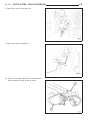
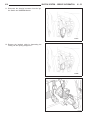
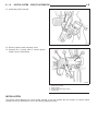
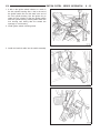
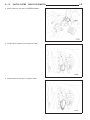
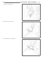
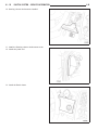
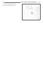
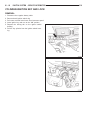
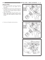
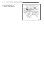
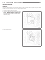
8I - 50
IGNITION SYSTEM - SERVICE INFORMATION
LX
SWITCH-IGNITION
REMOVAL
The ignition switch attaches to the lock cylinder housing on the end opposite the lock cylinder. For ignition switch
terminal and circuit identification, refer to the Wiring Diagrams section.
1. Disconnect negative cable from battery.
2. Remove the Instrument Panel Center Bezel, (Refer
to 23 - BODY/INSTRUMENT PANEL/CLUSTER
BEZEL - REMOVAL) Chrysler and (Refer to 23 BODY/INSTRUMENT PANEL/CLUSTER BEZEL REMOVAL) Dodge.
3. Bezel cluster removed.
LX
4. Remove side trim panel to steering column cover.
5. Remove the screws that secure the steering column cover to the instrument panel and relocate
panel.
6. Pull the steering column cover rearward at the top
and right side of the cover to release the snap
retainers from the instrument panel.
7. Remove the screws that secure the instrument
panel steering column cover reinforcement to
bracket and remove reinforcement from the vehicle.
IGNITION SYSTEM - SERVICE INFORMATION
8I - 51
8I - 52
IGNITION SYSTEM - SERVICE INFORMATION
8. Remove the 2 front mounting nuts.
9. Remove the lower mounting nut.
10. Slide the assembly rearward into the instrument
panel and down to gain access to switch.
LX
LX
11. Disconnect the electrical connector from the ignition Switch and SKREEM Module.
12. Remove the interlock cable by depressing the
locking tab and pulling straight out.
IGNITION SYSTEM - SERVICE INFORMATION
8I - 53
8I - 54
IGNITION SYSTEM - SERVICE INFORMATION
LX
13. Interlocking cable removed.
14. Remove ignition switch mounting screw.
15. Squeeze the 2 locking tabs to remove ignition
switch from the lockhousing.
1
2
3
4
-
Ignition Key Housing
Ignition Switch
Ignition Switch Mounting Screws
Locking Tabs
INSTALLATION
The ignition switch attaches to the lock cylinder housing on the end opposite the lock cylinder. For ignition switch
terminal and circuit identification, refer to the Wiring Diagrams section.
LX
1. A tab on the ignition switch indexes to a notch in
the lock cylinder housing. Also, a slot in the end of
the ignition switch fits over the shaft in the end of
the lock cylinder housing. Use the ignition key to
rotate the lock cylinder to align the ignition switch
with lock cylinder housing. Insert ignition switch into
lock housing until locking tabs are seated into
openings on lock housing.
2. Install ignition switch mounting screw.
3. Install the interlock cable into the switch assembly.
IGNITION SYSTEM - SERVICE INFORMATION
8I - 55
8I - 56
IGNITION SYSTEM - SERVICE INFORMATION
4. Attach electrical connector to SKREEM Module.
5. Install switch assembly into Instrument Panel.
6. Attach electrical connector to ignition switch.
LX
LX
7. Tighten the 2 mounting nuts.
8. Tighten the lower mounting nut.
9. Install steering column reinforcement.
IGNITION SYSTEM - SERVICE INFORMATION
8I - 57
8I - 58
IGNITION SYSTEM - SERVICE INFORMATION
10. Steering column reinforcement installed.
11. Install the Steering column reinforcement cover.
12. Install trim panel end.
13. Install the Bezel cluster.
LX
LX
14. Install the ignition switch bezel ring.
15. Connect the negative battery cable.
IGNITION SYSTEM - SERVICE INFORMATION
8I - 59
8I - 60
IGNITION SYSTEM - SERVICE INFORMATION
CYLINDER-IGNITION KEY AND LOCK
REMOVAL
1.
2.
3.
4.
Disconnect the negative battery cable.
Remove bezel ignition switch ring.
Pull center console bezel loose from instrument panel.
Insert ignition key and turn to the “ON” position.
5. Depress the locking tab on the ignition switch
housing.
6. Pull the key cylinder from the ignition switch housing.
LX
LX
INSTALLATION
1. Install key in lock cylinder. Turn key to “ON” position (retaining tab on lock cylinder can be
depressed).
2. The shaft at the end of the lock cylinder aligns with
the socket in the end of the housing. To align the
socket with the lock cylinder, ensure the socket is
in the “ON” position.
3. Align the lock cylinder with the grooves in the
housing. Slide the lock cylinder into the housing
until the tab sticks through the opening in the
housing.
4. Turn key to Off position and remove key.
IGNITION SYSTEM - SERVICE INFORMATION
8I - 61
8I - 62
IGNITION SYSTEM - SERVICE INFORMATION
5. Install center console bezel to instrument panel.
6. Install bezel ignition switch ring.
7. Connect the negative battery cable.
LX