1
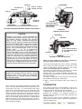
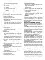
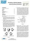
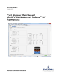
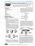
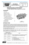
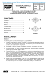
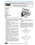
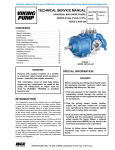
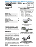
TECHNICAL SERVICE MANUAL
INSTALLATION, START-UP, TROUBLESHOOTING,
PREVENTATIVE MAINTENANCE, DO’S AND DON’TS
CONTENTS
4.
Installation, General Comments
Foundation
Alignment
Piping
Start Up
Troubleshooting
Preventative Maintenance
Rapid Wear
Do’s and Don’ts
Warranty
1
2
3
3
4
5
6
7
8
9
GENERAL
Location - always locate the pump as close as possible
to the supply of liquid to be pumped. Locate it below the
liquid supply if at all practical. Viking pumps are self
priming but the better the suction conditions the better
the performance.
2.
Accessibility - the pump should be located where it is
accessible for inspection, maintenance, and repair. For
large pumps, allow room to remove the rotor and shaft
without removing the pump from the base.
3.
Port Arrangement - since the pumps have different port
arrangements depending on the model, port location
should be checked before starting the installation. The
ports may be upright, opposite or at right angles to each
other, see Figure 1. The right angle ports are normally
right-hand, see Figure 2; some models are available with
left-hand arrangements; still other models are available
with the right angle ports located in any one of eight
positions including right-hand and left-hand.
1 OF 9
ISSUE
D
DISCHARGE
‘B’
‘A’
SUCTION
IDLER PIN
FIGURE 3
5.
FIGURE 1
LEFT HAND PUMP
PAGE
Suction/Discharge - shaft rotation will determine which
port is suction and which discharge. A look at Figure 3
will show how rotation determines which port is which;
as the pumping elements (gears) come out of mesh,
point "A" on Figure 3, liquid is drawn into the suction
port; as the gears come into mesh, point "B", the liquid is
forced out the discharge port. Reversing the rotation
reverses the flow through the pump. When determining
shaft rotation, always look from the shaft end of the
pump. Unless otherwise specified, rotation is assumed
to be clockwise (CW), which makes the suction port on
the right side of the pump. The idler pin, which is offset
in the pump head, should be properly positioned toward
and an equal distance between the port connections.
Before installation is started a few items of a general nature
should be considered.
1.
BULLETIN TSM-000-V
RIGHT HAND PUMP
FIGURE 2
VIKING PUMP
P.O Box 398, 661 Grove Ave.
Windsor, Ontario, N9A 6M3, Canada
Pressure Protection - Viking pumps are positive
displacement. This means that when the pump is
rotated, liquid will be delivered to the discharge side of
the pump. If there is no place for this liquid to go discharge line is blocked or closed - pressure can build
up until the motor stalls, the drive equipment fails, a
pump part breaks or ruptures, or the piping bursts.
Because of this, some form of pressure protection must
be used with a positive displacement pump. This may
be relief valve mounted directly on the pump, an inline
relief valve, a torque limiting device or a rupture disk.
The pressure relief valve mounted on Viking pumps and
most in-line valves are of the spring loaded poppet
design See Figure 4. The spring (A) holds poppet (B)
against the seat in the valve body (C) with a given force
determined by the spring size and by how tightly it is
compressed by the adjusting screw (D). The pump
discharge pressure pushes against the underside of the
poppet at point (E). When the force exerted by the liquid
under the poppet exceeds that exerted by the spring, the
poppet lifts and liquid starts to flow through the valve.
DISCHARGE
SPRING (A)
VALVE BODY (C)
POPPET (B)
CAP SHOULD ALWAYS
POINT TOWARD SUCTION
PORT
PUMP HEAD
POINT (C)
ADJUSTING
SCREW (D)
LIQUID INLET
LIQUID OUTLET
SUCTION
ADJUSTING SCREW
CAP (SHOULD ALWAYS
POINT TOWARD
SUCTION PORT)
CUT-AWAY OF MAGNUS INTERNAL RELIEF VALVE FIGURE 4
FIGURE 5A
INTERNAL RELIEF VALVE
CAUTION
INTERNAL TYPE RELIEF VALVES MOUNTED ON
VIKING PUMPS SHOULD ALWAYS HAVE THE CAP
OR BONNET POINTED TOWARD THE SUCTION
SIDE OF THE PUMP. RETURN-TO-TANK-TYPE
RELIEF VALVES SHOULD ALWAYS BE MOUNTED
ON THE DISCHARGE SIDE OF THE PUMP. IF PUMP
ROTATION IS REVERSED, CHANGE THE RELIEF
VALVE. TURN THE INTERNAL TYPE END FOR END;
MOVE THE RETURN-TO-TANK TYPE TO THE
OTHER PORT.
IF, ON A PARTICULAR
INSTALLATION ROTATION IS REVERSED, e.g.,
USING ONE PUMP TO FILL A TANK AND THEN BY
USE OF A REVERSING SWITCH OR OTHER MEANS
CHANGING THE ROTATION TO PERMIT THE SAME
PUMP TO CIRCULATE THE LIQUID THROUGH A
HEATER OR TO LOAD OUT) THEN PRESSURE
PROTECTION MUST BE PROVIDED ON BOTH
SIDES OF THE PUMP OR FOR BOTH ROTATIONS.
THIS MAY BE A COMBINATION OF RELIEF VALVES,
TORQUE LIMITING DEVICES OR RUPTURE DISKS.
PUMPS OR SYSTEMS WITHOUT RELIEF VALVES
SHOULD HAVE SOME FORM OF PRESSURE
PROTECTION, E.G., TORQUE LIMITING DEVICES
OR RUPTURE DISKS.
DISCHARGE
PUMP HEAD
VALVE ALWAYS MOUNTS
ON THE DISCHARGE SIDE
OF THE PUMP
SUCTION
FIGURE 5B
RETURN-TO-TANK RELIEF VALVE
NOTE: on some models the relief valve is mounted on
the pump casing instead of the pump head.
The spring loaded poppet-type valve is strictly a differential
valve, sensing only those pressures on each side of the
poppet. It should not be used as a pressure or flow control
device. It is intended strictly as a relief valve.
The pressure at which either the return-to-tank or internal
relief valve bypasses can be changed by turning the
adjusting screw. Do not back the adjusting screw all the way
out. Stop when spring tension is off the screw (the screw
starts to turn easily).
For details on maintenance of the relief valve see Technical
Service Manual covering your model series.
6. Motor - follow local electrical codes when booking up
motors.
Viking pumps can be furnished with either an internal relief
valve - one which directs the flow from the valve back to the
suction side of the pump - or a return-to-tank valve which
directs the flow through piping back to the supply tank. See
Figure 5. An inline relief valve mounted in the discharge
piping also directs the flow back to the supply tank. This type
of valve should be mounted close to the pump so that the
pressure drop through the piping between the pump and the
valve is at a minimum. Be sure there are no shutoff valves
between the pump and relief valve. Piping from a return-totank or an in-line valve to the supply tank should also be as
short and large as possible.
FOUNDATION
Every pump should have a solid foundation. It may be any
structure sufficiently strong to hold the pump rigid and to
absorb any strain or shock that may be encountered.
A certified print of the pumping unit should be used in
preparing the foundation. If a separate foundation is
provided, make it at least four inches wider and longer than
the base of the unit.
When the unit is placed on the foundation it should be
leveled and checked for position against the piping layout
and then fastened down.
BULLETIN TSM-000-V
ISSUE
D
PAGE 2 OF 9
ALIGNMENT
PIPING
CHECK ALIGNMENT AFTER MOUNTING
The cause of many pumping problems can be traced to
suction piping. It should always be as large and short as
practical. For help in selecting the proper size piping, both
suction and discharge, refer to Viking General Catalogue.
For detailed coupling alignment procedures see Viking
service bulletin ESB-61.
The pump, drive, and motor were properly aligned at the time
they were assembled. During shipping and mounting the
alignment is often disturbed. BE SURE TO RECHECK
ALIGNMENT AFTER THE PUMP UNIT IS INSTALLED!
Before starting layout and installation of your piping system,
consider the following points:
1. Check pump ports to be sure they are square and in
proper position; shim or move pump as required. Do not
force piping to line up with the ports.
2. Be sure the inside of the pipe is clean before booking it
up.
2. If the pump is driven by a flexible coupling(s) either direct
connected to the motor or through a reducer, remove any
coupling guards or covers and check alignment of the
coupling halves. A straightedge (a piece of key stock
works nicely) across the coupling must rest evenly on both
rims at the top, bottom, and sides. See Figure 6.
1. Never use piping smaller than the pump port connections.
3. Foot valve - When pumping a light liquid with a suction lift,
a foot valve at the end of the suction piping or a check
valve in the first horizontal run will hold the liquid in the
line and make it easier for the pump to prime. Be sure the
foot or check valve is big enough so that it doesn't cause
excessive line loss.
3. If the pump is driven by V-belts, check the alignment by
using a long straightedge or tightly drawn string across the
face of the sheaves. See Figure 6A.
4. Make a final check on alignment after piping is hooked up.
See item 13 under "Installation - Piping".
Figures 7,8, and 9 show typical units - direct, gear reducer
and V-belt drive.
5. For high temperature applications (those above 300°F)
allow pump to reach operating temperature, then recheck
alignment.
USE A STRAIGHT EDGE. THESE
SURFACES MUST BE PARALLEL.
FIGURE 7
DIRECT DRIVE
CHECK WIDTH BETWEEN THESE SURFACES
WITH INSIDE CALIPERS TO BE CERTAIN THE
FACES ARE EQUAL DISTANCE APART AND
PARALLEL.
FIGURE 8
GEAR REDUCER DRIVE
FIGURE 6
DRIVER SHEAVE
STRING
DRIVEN SHEAVE
STRAIGHT
EDGE
FIGURE 9
V-BELT DRIVE
WHEN SHEAVES PROPERLY ALIGNED ALL POINTS A, B, C,
D WILL TOUCH STRING OR STRAIGHTEDGE.
FIGURE 6A
BULLETIN TSM-000-V
ISSUE
D
PAGE 3 OF 9
4.
When approaching an obstacle in the suction or
discharge line, go around the obstacle instead of over it.
Going over it creates an air pocket. See Figure 10.
NOT THIS
THIS
OBSTRUCTION
OBSTRUCTION
GO AROUND THE
OBSTRUCTION ON
THE HORIZONTAL
DO THIS
KEEP LONG
HORIZONTAL LINE
NEAR LIQUID LEVEL
NOT THIS
FIGURE 10
FIGURE 11
5.
6.
Where practical, slope the piping so no air or liquid
pockets will be formed. Air pockets in the suction line
make it hard for the pump to prime.
For a suction line with a long horizontal run keep the
horizontal portion below the liquid level if possible. This
keeps the pipe full so the pump does not have to remove
so much air when starting; this is most helpful when
there is no foot valve. See Figure 11.
7.
When piping a hot or cold system (liquid being handled
is at a temperature different from the air surrounding the
pump), be sure allowance is made for expansion and
contraction of the piping. Loops, expansion joints, or
unsecured (this does not mean unsupported) runs
should be used so the pump casing is not distorted or
put into a bind.
8.
STRAINER - It is always good practice to consider a
strainer on the suction side of a positive displacement
pump. The strainer will keep foreign objects from going
into the pump; without a strainer some would go through;
others would cause a jammed pump, a broken part, or a
torn up drive. The strainer basket mesh or perforation
size should be big enough so that it does not cause
excessive pressure drop, but it should be fine enough to
protect the pump. When in doubt as to the proper size,
check with the manufacturer, giving him pipe size, flow
rate, and viscosity involved. Provision should be made
for cleaning the strainer. If the pump operates
continuously, a bypass should be built around the
strainer or two strainers should be put in parallel with
proper valving so they can be isolated for cleaning. Use
of a strainer is particularly important at start up to help
clean the system of weld beads, pipe scale, and other
foreign objects. If the pump is not equipped with a relief
valve, consideration should be given to mounting one in
the discharge line. See discussion on relief valves under
START UP.
10. The pump should not be used to support the piping. The
weight of the pipe should be carried by hangers,
supports, stands, etc.
11. When fastening the piping to the pump it should not be
necessary to impose any strain on the pump casing.
"Springing" or "drawing" the piping up to the pump will
cause distortion, possible misalignment, and probable
rapid wear of the pump. Do not use the pump to correct
errors in piping layout or assembly.
12. All joints of the piping system should be tight; pipe sealer
or Teflon tape will help assure leak-free threaded joints.
Leaks in the suction line permitting air to be drawn in
may cause a noisy pump, or a reduction in capacity.
13. ALIGNMENT - Check the alignment of the drive after the
piping is hooked up. As a final check on pump alignment
remove the head of the pump and with a feeler gauge
determine if there is clearance all the way around
between the rotor and casing. Because of manufacturing
tolerances, bushing clearances, etc., the rotor may not
be centered in the casing, but it should not drag;
dragging would indicate unit misalignment or casing
distortion from piping strain. Making this check is most
desirable on installations involving Q, M and N size
standard duty pumps.
14. The auxiliary piping hooked to jackets, glands, etc. for
heating, cooling, quenching, or for other purposes
should receive the same attention as the piping handling
the liquid pumped.
15. Provide a relief device in any part of a pump and piping
system that can be valved off and, thus, completely
isolated. This is particularly important:
a). When handling a cold liquid such as refrigeration
ammonia that can warm up to ambient temperatures
when the pump is shut off or
b). When handling a liquid such as asphalt or molasses
that has to be heated before it can be pumped.
The rise in temperature causes the liquid to expand;
if there is no provision for pressure relief in the
closed off section, there is a chance that the pump
or piping will rupture.
START UP
Before pushing the "start" button, check the following:
1.
Are there vacuum and pressure gauges on or near the
pump? These gauges are the quickest and most
accurate way of finding out what is happening in the
pump.
BULLETIN TSM-000-V
ISSUE
D
PAGE 4 OF 9
2.
Check alignment - See suggestions under "Installation Alignment" in this manual.
3.
Check piping to be sure there is no strain on the pump
casing.
4.
Rotate the pump shaft by hand to be sure it turns freely.
MAKE SURE THE PUMP DRIVER IS LOCKED OUT
OR CANNOT BE ENERGIZED BEFORE DOING THIS.
TROUBLESHOOTING
5.
Jog motor to be sure it is turning in the right direction;
see discussion on pump rotation under "Installation General" item 4 in this manual.
A Viking pump that is properly installed and maintained will
give long and satisfactory performance.
NOTE: Before making any pump adjustment or opening the
pump liquid chamber in any manner, make sure that:
6.
Check any relief valves to be sure they are installed
correctly. See discussion on relief valves under
"Installation - General".
1)
7.
Check suction piping to be sure (a) it is all connected
and tight, (b) valves are open, and (c) end of pipe is
below liquid level.
2)
8.
Check discharge piping to be sure (a) it is connected
and tight, (b) valves are open, and (c) there is a place for
the liquid to go.
3)
9.
Lubricate any grease fitting on the pump using a good,
general purpose #2 ball bearing grease. Check any gear
reducer, motor, coupling, etc. for instructions and
lubricate as recommended. See Engineering Service
Bulletin ESB-515.
10. For packed pumps, loosen packing gland nuts so gland
can be moved slightly by hand. Adjust gland to reduce
leakage only after pump has run long enough to reach
constant temperature. Packing should weep a little to
keep it cool and lubricated.
11. Do not use the Viking pump to flush, pressure test or
prove the system with water. Either remove the pump or
run piping around it while flushing or testing. Pumping
water, dirty or otherwise, can do more damage in a few
minutes than months of normal service.
12. Check to be sure all guards are in place.
13. Now you are ready to push the "start" button - gently.
If the pump begins to deliver liquid within 60 seconds, you're
in business. If it does not, push the "stop" button. Do not run
the pump longer than one minute without liquid in it; you may
damage it. Review the steps just outlined, consider what the
suction and discharge gauges indicate, see page 6; if
everything appears to be in order, put some liquid in the
pump, a lubricating liquid is best. This will help it prime.
Push the "start" button again. If nothing is flowing within two
minutes, stop the pump. The pump is not a compressor, it will
not build up much air pressure; it may be necessary to vent
the discharge line until liquid begins to flow.
If the pump still does not deliver, the cause may be one or
more of the following:
1. Suction line air leaks; vacuum gauge reading should help
determine if this is the problem.
2. End of suction pipe not submerged deep enough in liquid.
3. Suction lift is too great or the suction piping is too small.
4. Liquid is vaporizing in the suction line before it gets to the
pump.
If after consideration of these points it still does not
pump, suggest you review again all points given under
START UP; read through Troubleshooting in this manual
and try again. If it still does not pump, contact your
Viking representative.
Any pressure in the pumping chamber has been vented
through the suction or discharge lines or other openings
provided for this purpose,
The driver has been "locked out" so that it cannot
inadvertently be started while work is being done on the
pump and
The pump has been allowed to cool down to the point
where there is no chance of anyone being burned.
If trouble does develop, one of the first steps toward finding
the difficulty is to install a vacuum gauge in the suction port
and a pressure gauge in the discharge port. Readings on
these gauges often will give a clue as to where to start
looking for the trouble.
Vacuum Gauge - Suction Port
1. High reading would indicate a).
b).
c).
d).
Suction line blocked - foot valve stuck, gate valve
closed, strainer plugged.
Liquid too viscous to flow through the piping.
Lift too high.
Line too small.
2. Low reading would indicate a).
b).
c).
d).
Air leak in suction line.
End of pipe not in liquid.
Pump is worn.
Pump is dry - should be primed.
3. Fluttering, jumping, or erratic reading a).
b).
c).
Liquid vaporizing.
Liquid coming to pump in slugs, possibly an air leak
insufficient liquid above the end of the suction pipe.
Vibrating from cavitation, misalignment, or damage
parts.
Pressure Gauge - Discharge Port
1. High reading would indicate a).
b).
c).
d).
e).
f).
g).
h).
High viscosity and small and/or long discharge line.
Gate valve partially closed.
Filter plugged.
Vertical head did not consider a high specific gravity
liquid.
Line partially plugged from build up on inside of
pipe.
Liquid in pipe not up to temperature.
Liquid in pipe has undergone a chemical reaction
and has solidified.
Relief Valve set too high.
2. Low reading would indicate a).
Relief valve set too low.
BULLETIN TSM-000-V
ISSUE
D
PAGE 5 OF 9
b).
c).
d).
e).
E). Pump takes too much power.
Relief valve poppet not seating properly.
Bypass around the pump partially open.
Too much extra clearance.
Pump worn.
3. Fluttering, jumping, or erratic reading a). Cavitation.
b). Liquid coming to pump in slugs.
c). Air leak in suction line.
d). Vibrating from misalignment
problems.
1.
2.
3.
or
mechanical
Some of the following may also help pinpoint the problem:
A). Pump does not pump.
1.
Lost its prime - air leak, low level in tank, foot valve
stuck.
2. Suction lift too high.
3. Rotating in wrong direction.
4. Motor does not come up to speed.
5. Suction and discharge valves not open.
6. Strainer clogged.
7. Bypass valve open, relief valve set too low, relief valve
poppet stuck open.
8. Pump worn out.
9. Any changes in the liquid system, or operation that
would help explain the trouble, e.g. new source of
supply, added more lines, inexperienced operators, etc.
10. Too much end clearance.
11. Head position incorrect. See Fig. 3.
B). Pump starts, then loses its prime.
1.
2.
3.
4.
Supply tank empty.
Liquid vaporizing in the suction line.
Air leaks or air pockets in the suction line; leaking air
through packing or mechanical seal.
Worn out.
C). Pump is noisy.
1.
2.
3.
4.
5.
6.
7.
Pump is being starved (heavy liquid cannot get to pump
fast enough). Increase suction pipe size or reduce
length.
Pump is cavitating (liquid vaporizing in the suction line).
Increase suction pipe size or reduce length; if pump is
above the liquid, raise the liquid level closer to the pump;
if the liquid is above the pump, increase the head of
liquid.
Check alignment.
May have a bent shaft or rotor tooth. Straighten or
replace.
Relief valve chatter; increase pressure setting.
May have to anchor base or piping to eliminate or
reduce vibration.
May be a foreign object trying to get into the pump
through the suction port.
D). Pump not up to capacity.
1.
2.
3.
4.
5.
6.
7.
8.
9.
Starving or cavitating - increase suction pipe size or
reduce length.
Strainer partially clogged.
Air leak in suction piping or along pump shaft.
Running too slowly; is motor the correct speed and is it
wired up correctly.
Bypass line around pump partially open.
Relief valve set too low or stuck open.
Pump worn out.
Too much end clearance.
Head position incorrect. See Fig. 3.
4.
5.
6.
Running too fast - Is correct motor speed, reducer ratio,
sheave size, etc. being used?
Is liquid more viscous than unit sized to handle; heat the
liquid, increase the pipe size, slow the pump down, or
get a bigger motor.
Discharge pressure higher than calculated, check
with pressure gauge. Increase size or reduce length
of pipe, reduce speed (capacity), or get bigger
motor.
Packing gland drawn down too tight.
Pump misaligned.
Extra clearance on pumping elements may not be
sufficient for operating conditions. Check parts for
evidence of drag or contact in pump and increase
clearance where necessary.
F). Rapid Wear.
On most applications the pump will operate for many months
or years before it gradually loses its ability to deliver capacity
or pressure. Examination of such a pump would show a
smooth wear pattern on all parts. Rapid wear, occurring in a
few minutes, hours or days, shows up as heavy grooving,
galling, twisting, breaking or similar severe signs of trouble.
SEE CHART PAGE 7.
PREVENTATIVE MAINTENANCE
Performing a few preventative maintenance procedures will
extend the life of your pump and reduce the overall cost of
ownership.
A). Lubrication - Grease all grease nipples after every 500
hours of operation or after 60 days, whichever occurs first. If
service is severe, grease more often. Do it gently with a hand
gun. Use a NLGI #2 grease for normal applications. For hot
or cold applications use appropriate grease. See Engineering
Service Bulletin ESB-515.
B). Packing Adjustment - Occasional packing adjustment
may be required to keep leakage to a slight weep; if
impossible to reduce leakage by gentle tightening, replace
packing or use different type. See Technical Service Manual
on particular model series for details on repacking.
C). End Clearance Adjustment - After long service the
running clearance between the end of the rotor teeth and the
head may have increased through wear to the point where
the pump is losing capacity or pressure. Resetting end
clearance will normally improve pump performance. See
TSM on particular model series for procedure on adjusting
end clearance for pump involved.
D). Examine Internal Parts - Periodically remove the head,
examine idler and bushing and head and pin for wear.
Replacing a relatively inexpensive idler bushing and idler pin
after only moderate wear will eliminate the need to replace
more expensive parts at a later date. See TSM on particular
model series for procedure in removing head of the pump. Be
sure idler does not slide off idler pin as head is removed and
drop and hurt someone or damage the part.
E). Cleaning the Pump - A clean pump is easier to inspect,
lubricate, adjust, and runs cooler; plus, it looks better.
F). Storage - If pump is to be stored, or not used for six
months or more, pump must be drained and a light coat of
non-detergent SAE 30 weight oil must be applied to all
internal pump parts. Lubricate fittings and apply grease to
pump shaft extension. Viking suggests rotating pump shaft
by hand one complete revolution every 30 days to circulate
the oil. Retighten all gasketed joints before using the pump.
BULLETIN TSM-000-V
ISSUE
D
PAGE 6 OF 9
RAPID WEAR
CAUSE
1.
2.
3.
4.
5.
6.
7.
ABRASIVES
CORROSION
EVIDENCE
POSSIBLE SOLUTION
Gouges or marks made by large, hard
particles; a rapid wearing away of
bushings from very small abrasives similar
to pumice; or anything in between.
Flush the system with the pump removed.
Install strainer in suction line. Oftentimes after
a system has run for a few cycles or a few
days the dirt is pretty well cleaned out and if
the pump is rebuilt into good condition it will
then last for a long time.
Rust, pitting or metal appears to be
“eaten” away.
Check the Viking General Catalog Liquid List
for materials of construction recommendation.
Consider whether all of the materials used in
pump construction were attacked; consider
other materials used in the system to
determine how they resisted the liquid. Check
to see whether or not the liquid has been
contaminated to make it more corrosive than
anticipated.
Noisy operation, broken bushings, twisted
shaft, parts show evidence of high heat
(discoloration).
Review General Catalog for operating limits on
particular model involved.
Pump may stall. Evidence of heavy
contact between end of rotor teeth and
head or other parts.
Increase end clearance and/or contact your
distributor or the factory with details of the
application so that information regarding
proper extra clearance may be provided.
Noisy bearings, localized heating at
bearings or lip seal, smoke, rapid bushing
wear.
Be sure all grease fittings are greased before
starting and instructions for lubrication of drive
equipment are followed; consider use of
auxiliary lubricating equipment.
MISALIGNMENT
Wear on only one part of a surface, e.g.,
one side of the casing, one side of the
packing gland, only a portion of the face of
the head.
Double check alignment of drive equipment
and piping. Check the alignment under
conditions as close to operating conditions as
possible.
RUN DRY
Pump stalls because parts have uneven
expansion caused by frictional heat;
galling between surfaces having relative
motion; seal seats and idler pins changing
colour because of high heat.
Be sure there is liquid in the system at the time
of start up. Provide some kind of automatic
alarm or shut-off if supply tank runs dry.
EXCEEDING
OPERATING LIMITS
INSUFFICIENT EXTRA
CLEARANCE
LACK OF
LUBRICATION
BULLETIN TSM-000-V
ISSUE
D
PAGE 7 OF 9
DO'S AND DON'TS Do's and Don'ts for installation, operation, and maintenance
of Viking pumps to assure safe, long, trouble-free operation.
MAINTENANCE 1.
Do make sure any pump that has residual system
pressure in it or that has handled high vapour pressure
liquids, e.g., LP-gas, ammonia, Freons, etc. has been
vented through the suction or discharge lines or other
openings provided for this purpose.
2.
Do make sure that if the pump is
driver while maintenance is being
driver has been "locked out" so
inadvertently started while work is
pump.
3.
Do make sure any pump that has handled a corrosive,
flammable, hot, or toxic liquid has been drained, flushed,
vented and/or cooled before it is disassembled.
4.
Don't drop parts during disassembly, e.g., idler can slip
from the pin as the head is removed from the pump; it
may drop on your foot, plus, it may get nicked or
gouged.
5.
Don't stick fingers in the ports of a pump! Serious injury
may result.
6.
Don't spin the idler on the idler pin! Fingers may be
jammed between teeth and crescent.
7.
Do remember that a few simple preventative
maintenance procedures such as periodic lubrication,
adjustment of end clearance, examination of internal
parts, etc., will extend the service life of your pump.
8.
Do obtain, read and keep maintenance instructions
furnished with your pump.
9.
Do have spare parts, pumps or standby units available,
particularly if the pump is an essential part of a key
operation or process.
INSTALLATION 1.
Do install pump as close to supply tank as possible.
2.
Do leave working space around the pumping unit.
3.
Do use large, short, and straight suction piping.
4.
Do install a strainer in the suction line.
5.
Do double check alignment after the unit is mounted and
piping is hooked up.
6.
Do provide a pressure relief valve for the discharge side
of the pump.
7.
Do cut out the center of gaskets used as port covers on
flanged port pumps.
8.
Do record pump model number and serial number and
file for future reference.
OPERATION 1.
Don't run pump at speeds faster than shown in the
catalogue for your model.
2.
Don't require pump to develop pressures higher than
those shown in the catalogue for your model.
3.
Don't operate pumps at temperatures above or below
limits shown in the catalogue for your pump.
4.
Don't operate pumps without all guards being in place.
5.
Don't operate pump without a relief valve on the pump or
in the discharge piping; be sure valve is mounted and
set correctly.
6.
Don't exceed catalogue limits for temperature and
pressures of fluids in jacketed areas of pump.
7.
Don't use the pump in a system, which includes a steam
blow or an air or vapour blow or purge without provision
for over-speed shutdown in case the pump starts to act
as a turbine and over-speeds the drive.
8.
Don't operate the pump with all of the liquid bypassing
through a pump mounted internal type relief valve or
without any flow of liquid going through the pump for
more than a couple of minutes. Operation under either of
these conditions may result in a heat build-up in the
pump, which could cause hazardous conditions or
happenings.
BULLETIN TSM-000-V
ISSUE
still hooked to
performed that
that it cannot
being done on
D
the
the
be
the
PAGE 8 OF 9
TECHNICAL SERVICE MANUAL
INSTALLATION, START-UP, TROUBLESHOOTING,
PREVENTATIVE MAINTENANCE, DO’S AND DON’TS
BULLETIN TSM-000-V
PAGE
9 of 9
ISSUE
D
WARRANTY
Viking warrants all products manufactured by it to
be free from defects in workmanship or material for a
period of one (1) year from date of startup, provided
that in no event shall this warranty extend more than
eighteen (18) months from the date of shipment from
Viking. If, during said warranty period, any products
sold by Viking prove to be defective in workmanship
or material under normal use and service, and if such
products are returned to Viking’s factory at Windsor,
Ontario, transportation charges prepaid, and if the
products are found by Viking to be defective in
workmanship or material, they will be replaced or
repaired free of charge, FOB. Windsor, Ontario.
Viking assumes no liability for consequential
damages of any kind and the purchaser by acceptance
of delivery assumes all liability for the consequences
of the use or misuse of Viking products by the
purchaser, his employees or others. Viking will
assume no field expense for service or parts unless
authorized by it in advance.
Equipment and accessories purchased by Viking
from outside sources which are incorporated into any
Viking product are warranted only to the extent of and
by the original manufacturer’s warranty or guarantee,
if any.
THIS IS VIKING’S SOLE WARRANTY AND IS IN
LIEU OF ALL OTHER WARRANTIES, EXPRESSED
OR IMPLIED, WHICH ARE HEREBY EXCLUDED,
INCLUDING IN PARTICULAR ALL WARRANTIES
OF MERCHANTABILITY OR FITNESS FOR A
PARTICULAR PURPOSE. No officer or employee of
IDEX Corporation or Viking Pump Canada is
authorized to alter this warranty.
VIKING PUMP
P.O Box 398, 661 Grove Ave.
Windsor, Ontario, N9A 6M3, Canada
VIKING PUMP·
Copyright© 2004·