1
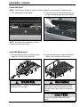
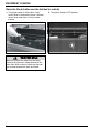
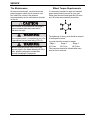
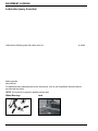
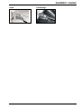
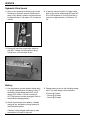
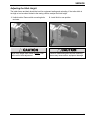
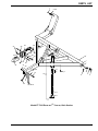
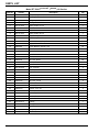
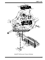
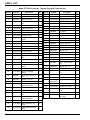
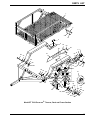
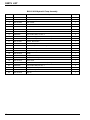
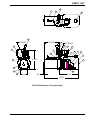
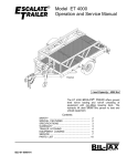
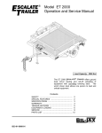
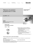
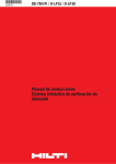
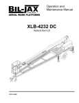
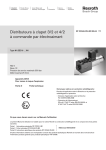
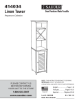
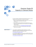
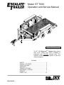
®
Model ET 7000
Operation and Service Manual
Load Capacity: 7000 lbs
The ET 7000 ESCALATE ® TRAILER offers ground
level roll-on loading and roll-off unloading of
equipment with non-tilting lowering deck. The
hydraulic lift deck allows one person to load and
unload equipment.
Contents
SAFETY ............................................................... 2
SPECIAL FEATURES ......................................... 2
SPECIFICATIONS ................................................ 3
WARRANTY ......................................................... 3
TRAILER HITCHING ........................................... 4
EQUIPMENT LOADING ...................................... 5
SERVICE .............................................................. 7
PARTS LIST ........................................................ 10
B33-01-0079
EQUIPMENT LOADING
Warnings and Cautions
Observe all warning labels on
the trailer. The trailer warning
labels are shown here as a
reminder. Other warnings and
cautions are included in this
manual.
WARNING
WARNING
Stand clear of trailer while deck is being raised or
lowered. Moving deck will create pinch points
causing serious crushing injury.
Stand clear of trailer while deck
is being lowered. Contact with
trailer deck will cause serious
crushing injury.
Failure to observe all warnings
may result in serious injury or
death. Failure to observe all
cautions may result in equipment
damage.
SPECIAL FEATURES
The Bil-Jax ESCALATE ® TRAILER includes all the features of a heavy duty trailer, plus:
Escalator Deck and Hydraulic Lift
Heavy Duty Tie-Down Brackets
Surge Brake and Adjustable Hitch
Optional Enclosure
2
SPECIFICATIONS
ESCALATE® TRAILER
Model Number ET 7000
Manufactured by:
Serial Number ________________
Bil-Jax, Inc.
125 Taylor Parkway
Archbold, Ohio 43502
419.445.9675
Specifications
With Optional Enclosure
Rated Capacity
7000 lbs. (3175 kg) max.
6000 lbs. (2722 kg) max.
Weight (Empty)
3000 lbs. (1361 kg)
3960 lbs. (1796 kg)
Overall Width
102 in. (259.1 cm)
102 in. (259.1 cm)
Overall Length
235 in. (596.9 cm)
235 in. (596.9 cm)
Overall Height (Bed
Raised)
Bed Height (Raised)
47 in. (119.4 cm)
111 in. (281.9 cm)
14 in. (35.6 cm)
14 in. (35.6 cm)
Bed Size (Flat Surface)
75 in. wide x 120 in. long
(190.5 cm wide x 304.8 cm long)
Overall Bed Size
(Including Ramp)
75 in. wide x 144 in. long
(190.5 cm wide x 365.8 cm long)
Ramp Grade
6 degrees
73 1/2 in. wide x 118 3/4 in. long x 90 1/2 in. high inside
(186.7 cm wide x 301.6 cm long x 229.9 cm high inside)
73 1/2 in. wide x 137 1/2 in. long x 90 1/2 in. high
(186.7 cm wide x 349.2 cm long x 229.9 cm high)
68 in. wide x 85” high (172.7 cm wide x 215.9 cm high)
door opening
6 degrees
Hitch Size
2-5/16 in. (5.87 cm) ball
2-5/16 in. (5.87 cm) ball
Suspension
Tandem Axle Leaf Spring
Tandem Axle Leaf Spring
Brakes
Standard – Hydraulic Surge;
Standard – Hydraulic Surge;
Optional – Electric
Optional – Electric
WARRANTY
Bil-Jax warrants its trailers for one year from the date of delivery against all defects of material and
workmanship, provided the unit is operated and maintained in compliance with Bil-Jax’s operating and
maintenance instructions; structural components are also warranted for one year. Bil-Jax will, at its
option, repair or replace any unit or component part which fails to function properly in normal use.
This warranty does not apply if the trailer and/or its component parts have been altered, changed, or
repaired without the consent of Bil-Jax or by anyone other than Bil-Jax or its factory trained personnel,
nor if the trailer and/or its components have been subjected to misuse, negligence, accident or any
conditions deemed other than those considered as occurring during normal use.
Components not manufactured by Bil-Jax are covered by their respective manufacturers warranties. A
list of those components and their warranties is available upon written request to Bil-Jax.
Bil-Jax shall not in any event be liable for the cost of any special, indirect or consequential damages to
anyone, product, or thing. This warranty is in lieu of all other warranties expressed or implied. We
neither assume nor authorize any representative, or other person, to assume for us any other liability in
connection with the sale, rental, or use of this product.
3
TRAILER HITCHING
Hook Up the Trailer
1. Raise trailer and open ball latch.
2. Line up ball with hitch.
NOTE: The trailer hitch uses a 2-5/16 inch ball.
3. Lower hitch onto ball and close ball latch.
4. Raise the jack.
NOTE: Trailer frame should be level when hitch
is on ball. See page 9 to adjust hitch height.
Always raise the jack before towing.
5. Hook safety chains and attach breakaway
cable.
6. Connect and check trailer lights.
Always cross safety chains below tongue.
Safety chains must hold tongue up if hitch fails.
Always check the tail lights and brake lights
before towing.
4
EQUIPMENT LOADING
Lower the Deck
NOTE: Trailer must be hitched to vehicle according to page 4 before lowering or raising the deck.
1. Turn power switch to ON position.
2. Hold control lever in the direction shown until
the deck reaches ground level, then release.
NOTE: The trailer frame should be on a level
surface when lowering the deck.
Load the Equipment
1. Load equipment so that the resulting tongue
weight is 15 to 20% of the total load.
2. Install tie-down straps to keep the load from
shifting. Use 8 tie-down anchors shown.
Maximum capacity = 7000 lbs. (enclosed trailer
is 6000 lbs.) Do not exceed.
Always secure the load with tie-down straps
before towing. Failure to properly secure the
load may result in injury, death, or equipment
damage.
Do not hook tie-down straps on the roller
guides.
5
EQUIPMENT LOADING
Raise the Deck (trailer must be hitched to vehicle)
1. Turn power switch to ON position. Hold
control lever in the direction shown. Release
control lever when deck is in fully raised
position.
Make sure people are away from the trailer
before raising the deck. Keep hands and feet
away from deck and rails. Hands and feet can
get crushed between the deck and frame.
6
2. Turn power switch to OFF position.
SERVICE
Tire Maintenance
At least once each week, use an accurate tire
pressure gage to check the air pressure in all
four trailer tires. Inflate to the pressure
recommended by the tire manufacturer (located
on the tire.
Wheel Torque Requirements
It is extremely important to apply and maintain
proper wheel mounting torque on your axle.
Wheel nuts should be retorqued after 50 miles
and 100 miles and periodically there after.
Low or uneven tire pressures will not properly
support a loaded trailer and could lead to
premature tire wear.
When replacing tires, it is important to use a tire
of appropriate size and load rating (75D-15).
Failure to maintain proper torque on the lug
nuts may result in the wheel shearing off of the
trailer, possibly causing an accident and
seriously damaging the equipment.
The tightening of the lug nuts should be torqued
in the sequence above.
Lug nuts should be torqued in stages:
Stage 1
Stage 2
Stage 3
25 Ft-Lbs
60 Ft-Lbs
100 Ft-Lbs
This procedure should be followed after each
time the tire is removed.
7
EQUIPMENT LOADING
Lubrication (every 6 months)
Lubricate the following parts with clean motor oil
or wheel
bearing grease
where shown.
For additional brake operating and service instructions, refer to the Surge Brake Actuator Manual
provided with the trailer.
NOTE: Be sure that no grease is applied to brake pad.
Wheel Bearings
8
Jack
EQUIPMENT LOADING
Hitch
Lift Bearings
9
SERVICE
Hydraulic Fluid Levels
1. Open cover enclosing hydraulic pump. Check
fluid level in hydraulic reservoir. When trailer
deck is fully raised, hydraulic fluid level should
be approximately 1 inch above 1/2 of reservoir
volume.
2. If reservoir volume is below 1/2 when trailer
deck is fully raised, add enough BP type HLP46 or 10W hydraulic oil to bring fluid level in
reservoir to approximately 1 inch above 1/2
full.
3. Remove fill cap from surge brake reservoir.
Add DOT 3 brake fluid as needed to bring
fluid level to 1/2-inch below fill port.
Battery
1. Use hydrometer to check battery charge daily
or weekly, depending on frequency of use. If
the battery charge drops below 25% of full
charge (S.G. below 1.155 as corrected to
80°F) the battery must be recharged. Refer to
step 2 before charging battery.
2. Check the electrolyte level weekly. If battery
charge is low, add water to bring electrolyte
level just above plates.
If battery is fully charged, add water to raise
electrolyte to full mark in each cell.
10
3. Charge battery at one of the following charge
rates. The slow charge rate is preferred.
22 hours @ 5 amps
25 hours @ 20 amps
22 hours @ 50 amps
SERVICE
Adjusting the Hitch Height
The trailer frame and deck should be level for equipment loading and unloading. If the trailer hitch is
too high or too low when hitched to the towing vehicle, readjust the hitch height.
1. Unhitch trailer. Remove hitch mounting bolts
and nuts.
2. Install hitch in new position.
Adjust hitch height when trailer is empty. Use
jack to aid in hitch adjustment.
Failure to install and tighten all hitch mounting
screws may cause serious equipment damage.
11
PARTS LIST
Model ET 7000 ESCALATE
Item No.
12
®
TRAILER, Hitch Section
Part No.
Description
Qty
1
0090-0346
Screw, Self-tapping, #10-24 x 3/4
8
2
B01-10-0179
Side Marker, Amber, Ear Mount – Front
2
2A
B01-10-0241
Side Marker, Red, Ear Mount – Rear
2
3
B01-10-0153
Plug Assembly, Marker Lights
2
4
B01-10-0152
Grommet, 2-1/2 inch
2
5
B01-10-0151
Side Light, Amber, 2-1/2 inch
2
6
0090-0344
Screw, Self-tapping, #10-24 x 1/2
3
7
0090-0042
Screw, Cap, 3/8-16 x 1
4
8
0090-0188
Nut, Lock, 3/8-16
4
9
B12-00-0115
Outer Tube Weldment, Jack
1
10
B23-02-0062
Tongue Jack Assembly (includes items 11 through 17)
1
11
B23-02-0066
Drop Leg, Quick Adjust
1
12
B25-00-0068
Kit, Bearing
1
13
B04-06-0030
Washer, 2.18 inch Square
1
14
B46-00-0028
Kit, Handle Replacement (includes items 15 & 16)
1
15
0090-0007
Screw, Cap, 1/4-20 x 1-1/4
1
16
0090-0183
Nut, Lock, 1/4-20
1
17
B36-00-0039
Pin
1
18
B03-00-0017
Safety Chain Assembly
2
19
0090-0081
Bolt, 1/2-13 x 5 inch
1
20
0090-0574
Washer, Flat, 1/2 inch
2
21
0090-0192
Nut, Lock, 1/2-13
1
22
B01-01-0134
Wiring Harness
1
23
B12-00-0068
Coupler, 2-5/16 inch
1
24
B12-00-0080
Hitch, Brake Surge Type
1
25
0090-0878
Bolt, 5/8-11 x 4-3/4 inch
5
26
0090-0425
Washer, Flat, 5/8 inch
10
27
0090-0194
Nut, Lock, 5/8 inch
5
28
B21-00-0023
Kit, Brake Line
1
29
B04-07-0032
Clamp, Hose
18
30
0090-0183
Nut, Lock, 1/4-20
18
31
B06-00-0357
Transfer, 2-5/16 Ball Hitch
1
PARTS LIST
1
2, 2A
29
28
24
26
27
30
16
26
15
25
26
23
21
14
9
26
8
25
20
”
/16
25
LL
BA
31
13
12
20
19
7
10
3
6
4
5
6
22
18
11
17
Model ET 7000 ESCALATE ® TRAILER, Hitch Section
13
PARTS LIST
Model ET 7000 ESCALATE ® TRAILER, Lift Section
Item No.
14
Part No.
Description
Qty
1
B02-05-0028
Pump Unit, Hydraulic, Manual Valve
1
2
B02-01-0147
Hose, Hydraulic
2
3
B02-02-0012
Fitting, Hydraulic
2
4
B01-04-0002
Battery, 12 V, 27 DCM
1
5
B01-01-0010
Battery Cable, 13 inch
1
6
0090-0162
Nut, Hex, 3/8-16
1
7
0090-0160
Nut, Hex, 5/16-18
1
8
B01-01-0013
Battery Cable, 30 inch
1
9
B07-06-5119
Strap, Battery Hold Down
1
10
B04-07-0003
Rod, Battery Hold Down, 1/4-20 x 10
2
11
B18-00-0147
Box w/Lid, Battery-Pump-Tool
2
12
B42-01-1014
Hinge, Continuous
2
13
0090-0231
Screw, Machine, #10-24 x 1/2
24
14
0090-0415
Washer, Flat, #10
40
15
0090-0182
Nut, Lock, #10-24
32
16
B42-00-0018
Latch, Draw
4
17
0090-0225
Screw, Machine, #8-32 x 1/2
20
18
0090-0181
Nut, Lock, #8-32
20
19
B01-02-0060
Switch, Master Power
1
20
B00-00-0112
Face Plate, Power Switch
1
21
B01-09-0018
Boot, Terminal
2
22
0090-0816
Nut, Hex, 5/16-24
1
23
B42-00-0019
Keeper, Draw Latch
4
24
B40-00-0029
Cable, Lid
4
25
0090-0232
Screw, Machine, #10-24 x 5/8
8
26
0090-0183
Nut, Lock, 1/4-20
2
27
0090-0419
Washer, Flat, 1/4
2
28
0090-0042
Screw, Cap, 3/8-16 x 1
6
29
0090-0210
Washer, Lock, 3/8
2
30
0090-0422
Washer, Flat, 3/8
6
31
0090-0900
Screw, Cap, 1-8 x 5 1/2
5
32
0090-0429
Washer, Flat, 1
10
33
0090-0689
Nut, Lock, 1-8
5
34
B12-00-0114
Linkage
1
35
B12-00-0106
Linkage Plate Weldment
1
36
B02-03-0023
Hydraulic Cylinder
1
37
B02-02-0084
Fitting, Hydraulic
2
38
0090-0188
Nut, Lock, 3/8-16
4
PARTS LIST
12
13
14
15
11
17
18
3
2
10
16
1
9
7
6
5
8
4
2
21
28
22
19
24
14
25
15 14
5
30
11
38
18
36
33
32
23
37
17
2
20
32
31 30
29
28
32
33
19
27
26
31
33
32
35
32 31
33
32
32
31
34
31
32
32
33
Model ET 7000 ESCALATE® TRAILER, Lift Section
15
PARTS LIST
Model ET 7000 ESCALATE® TRAILER, Deck and Frame Section
Item No.
Part No.
1
B12-00-0105
2
16
Description
Qty
Item No.
Part No.
Description
Qty
Deck Weldment
1
33
0090-0042
Screw, Cap, 3/8-16 x 1
20
B12-00-0116
Bar, Guide
2
34
B32-00-0014
Seal, Bearing
4
3
0090-0428
Washer, Flat, 3/4
8
35
B25-00-0060
Bearing, Wheel, Inner
4
4
0090-0103
Screw, Cap, 3/4-10 x 21/2
4
35A
B25-00-0061
Bearing, Wheel, Outer
4
36*
B12-00-0071
Wheel Assembly, 6 Lug
4
5
B31-00-0034
Plate, Wear
2
37
0090-0882
Washer, Wheel
4
6
B12-00-0102
Frame Weldment
1
38
0090-0880
Nut, Castle
4
7
B01-10-0235
Tail Light, Oval
2
8
B01-10-0237
Plug, 3 Way, Oval
2
9
B01-10-0236
Grommet, Oval
2
10
B01-10-0153
Plug Assembly, Marker
Lights
2
11
B01-10-0239
Grommet, 2 inch
2
12
B01-10-0238
Side Light, Red, 2 inch
2
13
0090-0344
Screw, #10-24 x 1/2
2
14
B07-07-5029
Block, Suspension Pin
8
15
B07-07-1023
Suspension Pin
4
16
B07-06-5697
Suspension Pin Plate
8
17
0090-0958
Screw, Cap, 5/8-11 x 31/2
16
39
0090-0881
Pin, Cotter
4
40
B32-00-0013
Cap, Hub
4
41
B08-02-0003
Tire, 75D-15
4
42
0090-0624
Nut, Wheel Lug
24
43
B30-00-0051
Plate, Wear
2
44
0090-0422
Washer, Flat, 3/8
8
45
0090-0042
Screw, Cap, 3/8-16 x 1
8
46
B12-00-0121
Roller, Lift
4
47
0090-0429
Washer, Flat, 1
4
48
0090-0954
Bolt
4
49
B04-07-0117
Shaft, Cam Follower
4
50
0090-0949
Screw, Nylon, 1-8 x 1/2
4
18
B39-00-0042
Leaf Spring, Double Eye
4
51
B07-05-0109
Fender
2
19
B12-00-0127
Hanger, Leaf Spring
4
52
0090-0005
4
20
B39-00-0035
Hanger Kit, Tandem
Spring
2
Screw, Cap, 1/4-20 x
3/4
53
0090-0419
Washer, Flat, 1/4
24
21
0090-0970
U-Bolt, Leaf Spring
8
54
0090-0183
Nut, Lock, 1/4-20
12
22
B07-07-5030
Block, Leaf Spring
Clamp
4
55
0090-0013
Screw, Cap, 1/4-20 x 21/4
8
23
0090-0067
Screw, Cap, 1/2-13 x 11/2
8
56
B06-00-0161Y
Transfer, Bil-Jax
2
57
B06-00-0437
Transfer, 7000# Max.
1
24
0090-0422
Washer, Flat, 3/8
16
58
1
0090-0188
Nut, Lock, 3/8-16
16
Not
Replaceable
Plate, Serial #
25
26
B12-00-0109
Suspension Arm, Left
Rear, Right Front
2
59
B06-00-0312
Decal, “Moving Deck…”
2
60
B06-00-0436
Transfer, “ET 7000”
2
27
0090-0192
Nut, Lock, 1/2-13
2
61
B06-00-0317
0090-0574
Washer, Flat, 1/2
4
Decal, Escalate Trailer
Logo
2
28
29
0090-0078
Screw, Cap, 1/2-13 x 33/4
4
62
B06-00-0313
Decal, “Stand Clear…”
2
Ref.
B01-10-0240
30
B12-00-0110
Suspension Arm, Left
Front, Right Rear
2
Bracket, License Plate,
with Lamp
31
0090-0896
Nut, Lock, 3/8-16
20
32
B10-00-0033
Brake Assembly, Left
Hand
2
32A
B10-00-0032
Brake Assembly, Right
Hand
2
* Wheel assembly includes items 34, 35, 40, and 42.
PARTS LIST
1
2
3
4
5
57
6
54
53
55
56
9
48
53
51
47
62
52
7
8
20
10
46
49
14 61
16
17
13
18
15
58
50
20
21
45
44
19
43
21
18
59
60
19
24
29
28
28
23
25
27
28
26
33
36
27
®
40
34
35
Model ET 7000 ESCALATE
42
35A 37
38
30
32, 32A
12
41
20
22
24
23
29
25
28
31
11
39
TRAILER, Deck and Frame Section
17
PARTS LIST
B02-05-0028 Hydraulic Pump Assembly
Item No.
18
Part No.
Description
Qty
1
B02-15-0398
Motor, DC - 12V
1
2
B02-15-0399
Pump Assembly
1
3
B02-15-0400
Tank, Plastic
1
4
B02-15-0401
Tube, Interior Return
1
5
B02-15-0402
Tube, Relief Valve Return
1
6
B02-15-0403
Tube, Suction
1
7
B02-15-0404
Filter, Suction
1
8
0090-0975
Bolt, Socket Head, 1/4-20 x 3
4
9
B02-15-0405
Valve Assembly (includes items 10 & 11)
1
10
B02-15-0406
Switch Assembly Cam (includes item 11)
1
11
B02-15-0407
Contact, Start Switch
1
12
B02-15-0408
Elbow, 90 Degree, 3/8 Tube x 1/4 NPT
1
13
B02-15-0409
Adapter, Pump/Valve, 2-1/2 Long
1
14
B02-15-0410
Valve, Check
1
15
B02-15-0411
Handle Assembly
1
16
B02-15-0412
Clamp
1
17
B02-15-0413
Tube, Exterior Return
1
18
B02-15-0414
Connector Assembly
1
19
B02-15-0415
Valve, Relief
1
20
B02-15-0416
Bracket, Plate Mount, 3-1/4 Hole Spacing
1
21
0090-0976
Bolt, Socket Head, 3/8-16 x 1
2
22
B01-01-0010
Cable, 2GA x 13, Eyelet Ends
1
23
B02-15-0417
Base Assembly
1
24
B02-15-0418
Cap, Fill
1
PARTS LIST
23
1
22
ARC
C
H
YD
R AU LI
S
ON
H
M
24
15
"A" PORT
6 15/16"
12
"B" PORT
9
16
17
13
10
11
4
2
14
6
7
9 1/16"
18
5
3
19
20
21
8
3 1/4"
3/4"
9 1/4”
16 3/8”
B02-05-0028 Hydraulic Pump Assembly
19
125 Taylor Parkway
Phone 419-445-9675
Archbold, OH 43502
Fax 419-445-0367