1
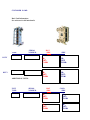
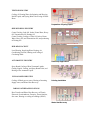
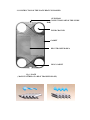
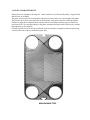
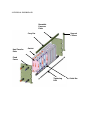
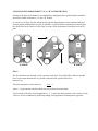
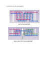
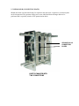
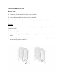
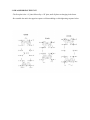
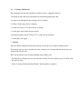
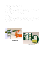
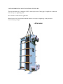
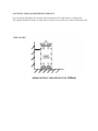
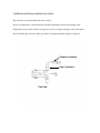
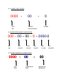
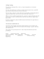
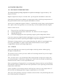
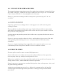
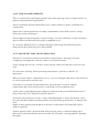
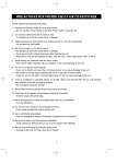
SEC HEAT EXCHANGERS
Plate and Frame
Service Manual rev.1
Table of Contents
Page 3
4
5 1.0
1.1
1.2
6-7 1.3
8 2.0
9 2.1
10 2.2
11 2.3
12 2.4
2.5
13 2.6
14 2.7
15 2.7.1
16 2.7.2
17 3.0
18 3.1
19 3.2
3.3
20 3.4
21 4.0
22 5.0
23 6.0
24 7.0
25 8.0
9.0
10.0
10.1
26 10.2
11.0
27 11.1
11.2
11.3
28 12.0
13.0
29 14.0
14.1
14.2
30 14.3
14.4
14.5
31 14.6
32 14.7
33 15.0
34 15.1
Name Plate Insert
Basic Unit Information Insert
Principles of the Plate Heat Exchanger
Principles
Features of PHE
Applications
Construction of the PHE
Plate Characteristics
Frame Components
Typical Fluid Flow
Construction of the Gasket
Construction and Application of the Frame
Fluid Flow Arrangement “A” to “B” Configuration
Typical Plate Arrangements Single Pass
Typical Plate Arrangements Multi Pass
Separator ( Connection Plate)
Dis-Assembling a Unit
Re-Assembling a Unit
Cleaning
Cleaning in Place (CIP)
Cleaning of Edible Oil
Tightening Devices
Transportation and Installation of the PHE
Installation and Minimum Clearance
Piping and Fitting on Multi Pass Units
Flushing a Unit before Start up
General Operating Instructions
Re-Gasketing
General Instructions for Glued Gaskets
Long Term Storage
Spare Parts Numbering System
Gasket Code System
Plates with Gasket Code System
Frame Component Code System
Pipe Loading
Assistance and Field Service
Trouble Shooting
Excessive Temperatures
Steam
Excessive Pressure and Spikes
Design Pressure
Pressure Spikes
Fluid Incompatibility
Leak Detection and Elimination
Service History Log
Service History Log
NAME PLATE:
To assist in a rapid reply to any questions please quote your serial number
PROCESS SIDE
SERVICE SIDE
DATE BUILT
UNIT TYPE
SERIAL NO.
SURFACE AREA
f2
DESIGN PRESS.
PSI
DESIGN TEMP.
C
TEST PRESS.
PSI
EMPTY WEIGHT
lbs
PLATE MAT’L.
GASKET MAT’L
CHANNEL ARRANGEMENT X PASS NO.
X
ORIGINAL TIGHTENING DISTANCE
WORK COVER APPROVAL No .
SEC Plate and Frame Heat Exchangers
2546 Iona Road, Belfast
Prince Edward Island
Canada C0A 1A0
Tel: 902.659.2424 / Toll Free: 800.335.6650
Fax: 902.659.2800 / Email: [email protected]
mm
CUSTOMER NAME:
Basic Unit Information:
See enclosure for full unit details
UNIT
TYPE:
SERIAL
NUMBER:
DUTY
DUTY
HOT
SIDE
COLD
SIDE
IN:
OUT:
FLOW:
IN:
OUT:
FLOW:
IN:
OUT:
FLOW:
IN:
OUT:
FOW:
ADDITIONAL UNITS:
UNIT
TYPE:
SERIAL
NUMBER:
HOT
SIDE
COLD
SIDE
IN:
OUT:
FLOW:
IN:
OUT:
FLOW:
IN:
OUT:
FLOW:
IN:
OUT:
FLOW:
1.0 PRINCIPLE OF THE PLATE HEAT EXCHANGER (PHE)
1.1 PRINCIPLE
The PHE is composed of corrugated thin alloy plates, which are hung between top and bottom guide
bars.
The plates are compressed by bolts in between fixed and movable frames, until metal to metal contact is
reached and a channel is formed. The manner in which the gaskets are fitted enables alternative flow
channels to be created and heat transfer to pass from one side of the plate to the other.
The alternative channels maximises the heat transfer surface in a compact manner. Therefore, it can
produce the most effective performance from the compact size.
1.2 FEATURES OF PHE
-
High performance : The total heat transfer co-efficient of the PHE is
2,000-6,00O Kcal/m2/hrC. The value is 3 to 10 times higher than the traditional shell and tube heat
exchanger.
-
High economic tendency: The PHE can maximise energy transfer efficiently from the unique
combination of high turbulence and thin plate technology for any given unit size.
-
Maintenance costs are also reduced due to it’s compact size.
-
Variety of Options: The PHE has been developed to allow many types of plates and gaskets for a
large number of applications.
Changing the number of plates or configuration of the plate pack allows for a change in duty
requirements in the shortest possible time. Maintenance is also greatly simplified, should
Re-gasketing or the cleaning of the plate surfaces be required.
-
Excellent versatility :
The PHE can carry out many kinds of processes from ice making, cooling, heating and
condensing or evaporation etc.with one set of suitable plates
-
High quality ISO9001 Certified:
The highest standards of manufacture are employed and combined with extensive technological
know how gained from over 20 years of experience the performance of your PHE is assured.
- All design and construction operations are performed by computerised systems. Performance
calculations are optimised for your particular duty requirements.
1.3 APPLICATIONS
CHEMICAL INDUSTRY
Cooling of Soda, Pigments, Fertilisers,
Refined Oils, Oil and Fat, Medicines, Acids,
Kerosene, Soft Water, Brine, Hexane,
Polymerisation Process and Heating of
Glycerine and Condensing of Ethanol
Cooling of oil Refinery, Intermediate Loop
STEEL INDUSTRY
Cooling of Mould, Furnace, Coking Plant,
Casting Facilities, Ammonia Water,
Electrolysis Gilt, Compressor, Oil Press Oil,
and Recovering of Waste Heats.
Concentrated Sulphuric Acid Cooling
MECHANICAL INDUSTRY
Cooling of Mechanical Apparatus, Emulsion,
Press Oil, Grinding Liquid, Furnace,
Engines, and Waste Heat Recovery.
Cooling of Continuous Casting Machine
FOOD INDUSTRY
Cooling, Heating, Heat Recovery,
Concentration, and Sterilisation of Juice,
Milk, Soy and Sesame Oil, Sugar Liquid,
and Alcoholic Liquids.
Juice Preheating Before Evaporation
TEXTILE INDUSTRY
Cooling of Cleaning Water for Spinning and Weaving,
NaOH Liquid, and Dyeing Water. Recovering of Waste
Heats.
Preparation of Dyeing Liquid
SHIP BUILDING INDUSTRY
Central Cooling, Lube Oil, Jacket, Piston Water, Heavy
Oil, Transmission Oil, Heating Oil
Central Cooling, Cooling of Lube Oil, Jacket, Piston
Water, Heavy Oil, and Transmission Oil, and preheating
of Heating Oil.
Ship Engine Cooling
BUILDING FACILITY
Local Heating, Supplying Water Heating, Air
Conditioning Systems, Heating and Cooling of
Circulating Water.
AUTOMOTIVE INDUSTRY
Heat Pump Applications
Spray Booth Cooling of Heat Treatment Liquids,
Cutting Liquids, Coating, and Spray Booth Paint, and
Heating of Pre-treatment Liquid.
PULP& PAPER INDUSTRY
Cooling of Black process water, Heating of incoming
Supply water, and Waste Heat Recovery.
Painting Installation
VARIOUS OTHER APPLICATIONS
Heat Transfer and Waste Heat Recovery of Electric,
Electronic, Semiconductor, Factories, Power Stations,
Sea water, Heating or cooling of buildings (HVAC).
Waste Heat Recovery
2. CONSTRUCTION OF THE PLATE HEAT EXCHANGER
GUIDE BAR
(CONNECTION PART OF THE GUIDE
BAR)
FLUID CHANNEL
GASKET
HEAT TRANSFER AREA
RING GASKET
Fig. 1 PLATE
( MAIN FEATURES OF A HEAT TRANSFER PLATE)
2.1 PLATE CHARACTERISTICS
Plate thickness is normally in the range 0.6-1.0mm. Stainless steel, Titanium, Hastelloy, Copper-Nickel
and Al-brass are available.
The plates are pressed to form corrugations which increase the surface area and strength of the plates.
The plate has up to four connection holes for fluid transfer, with gaskets fitted to confine the liquids.
Gaskets are made from composed rubber and are chosen in accordance with the types of fluids to be
used in the PHE. The corrugated shape on the plates maximises the heat transfer efficiency by creating
high turbulence in the channels.
Centrally located cut outs on the top and bottom ends of each plate is designed to make the plate hang
correctly either side to the top and bottom guide bars.
HERRINGBONE TYPE
2.2 FRAME COMPONENTS
PART
FRAME
PLATE
PRESSURE
PLATE
SUPPORT
COLUMN
UPPER
GUIDE BAR
LOWER
GUIDE BAR
QTY
1
1
1
1
1
DESCRIPTION
CARBON OR
STAINLESS
CARBON OR
STAINLESS
CARBON OR
STAINLESS
CARBON OR
STAINLESS
CARBON OR
STAINLESS
DETERMINED BY UNIT TYPE AND DESIGN
PART
HEAT TRANSFER
PLATE
TIGHTENING
BOLT
NAME PLATE
QTY
*
DESCRIPTION
ALLOY
*
HIGH TENSILE
1
STAINLESS
CONNECTION
NOZZLE
DRAIN VALVE
*
STAINLESS
*
STAINLESS
2.3 TYPICAL FLUID FLOW
Moveable
Pressure
Plate
Carry Bar
Heat Transfer
Plate
Support
Column
Gasket
Fixed
Frame
Tightening
Bolt
Guide Bar
2.4 CONSTRUCTION OF THE GASKET
The gaskets are designed as a duplicate structure to prevent mixing the fluids.
Should the ring gasket fail the liquid vents to the atmosphere (‘B’ part), and is prevented
from mixing with the opposing liquid by the diagonal gasket.
In a similar manner if the diagonal gasket fails the ring gaskets acts as a secondary seal.
2-5 CONSTRUCTION AND APPLICATION OF THE FRAME
The construction of the frames is dependent on the application, pressure requirements and
the type of the plates held in the frame.
The frames are protected from the liquids due to the welding or pressing of liners into the
appropriate connection.
In general terms the construction and operation of the frames is the same for all PHE’S
2-6 FLUID FLOW ARRANGEMENT “A” to “B” CONFIGURATION
Forming of the plate pack channels is accomplished by hanging the plates (gasketed plates should be
faced to the frame) in alternative “A” then “B” fashion.
As can be seen in Fig.6, the plate which has the ring and diagonal gasket on the right hand side and
chevron pattern pointing down, the plate is called the 'A' plate and when rotated becomes the 'B' plate.
One fluid flows on the surface of each of the 'A' plates, while the alternative fluid flows over the 'B'
plate.
A
B
A
B
B
'A' PLATE
A
'B' PLATE
FIG: 6
The flow directions are normally counter current to each other. The hot fluid flows with two parallel
lines, top to botton and bottom to top, and the cold fluid with 4 parallel lines flows
bottom to top.
The plate arrangement can be written as
2x2+1
4x1
where + 1 represents the end plate which does not perform any heat transfer.
The four holes in the plate are distinguished as 1, 2, 3, and 4 from their positions, and '0' means no hole.
There are 16 hole combinations possible depending on the application and temperature approach.
2.7 TYPICAL PLATE ARRANGEMENTS
EXAMPLE OF PLATE ARRANGEMENT AND FLOW
SINGLE PASS ARRANGEMENT
SINGLE AND MULTI PASS ARRANGEMENT
2.7.1 ADDITIONAL PLATE ARRANGEMENTS
MULTI PASS ARRANGEMENT
SINGLE & MULTI- MULTI PASS ARRANGEMENT
2.7.2 SEPARATOR (CONNECTION PLATE)
Should more than one heat transfer duty be required in the same unit, a separator or connection plate
can be incorporated. The separator allows two or more individual heat exchanger duties to be
performed and is especially suited to UHT pasteurisation duties.
SEPARATOR OR
CONNECTION
PLATES
HEAT EXCHANGER WITH
TWO CONNECTIONS
3.0 DISASSEMBLING A UNIT
Remove frame:
1) Remove any foreign material and apply grease to all bolts.
2) Loosen the intermediate bolts and remove from the frame.
3) Loosen the diagonals in sequence to maintain the pressure plate parallel to the frame plate.
Caution
Never allow the pressure plate to be at an angle to the plate pack as the plates maybe distorted, due to
excessive loading.
To Disassemble the plates:
1) Remove any foreign material and apply grease to the top guide bar for easier movement of the
plates.
2) Remove each plate one at a time in the direction of the arrows as shown, ensuring that the gasket is
not held onto the plate in front of it.
3.1 RE-ASSEMBLING THE UNIT
- The first plate is the “A” plate followed by a “B” plate, until all plates are hanging in the frame.
- Re-assemble the unit in the opposite sequence of disassembling see bolt tightening sequence below
3-2 CLEANING
Follow the next sequence to clean the plates after disassemble.
1) Clean the plates one by one with high pressure water or chemical clean in an appropriate acid or
caustic.
2) Remove clip-on gaskets and ensure the gasket groove is clean before reattaching the gasket.
Any foreign material left will cause the gasket to leak on resealing of the unit.
(3) Cleaning the gasket.
Do not use a steel brush or the gasket will be marked and a leak will occur on re-tightening of the
unit. Mild soap or water should be used with a cloth
(4) Should your unit have a corrosive duty, ensure that any opening of the unit is keep to a minimum.
This will prevent excessive swelling of the gasket. Ask your heat exchanger supplier for more details
on applicable duties.
5) Removing Calcium Deposition (Ask your heat exchanger supplier for details).
5-1) Submerge the plate in phosphoric or nitric acid
(nitric acid of specific gravity 1.4, 1 litre + water 10 litres ) for 5-10 minutes at normal
temp and rinse wash with water.
5-2. After acid cleaning passivate the plate with a neutraliser such as caustic and again rinse
clean with water.
3.3 Cleaning in Place (CIP) (Ask your heat exchanger supplier for details).
An alternative cleaning method is CIP cleaning which does not require the disassembling of the plate
pack see.
- Cleaning Brine:
- the brine should be expelled completely and then run the system with pure water at normal flow rates,
until the unit is clean.
Cleaning brine with hot water, follow the sequence above and loosen the retaining bolts for gasket's
expansion 100 plates / 5mm.
The flow rate of the cleaning water should be higher than the duty flow rate for maximum affect.
In chemical cleaning, the temperature and density of caustic are not that critical but for nitric or
phosphoric acids, higher temperatures accelerate the acids activity. Nitric acid should not be used on any
material, except stainless steel.
If the PH of the acid falls below 5, adjust to over 7 for improved performance.
3.4
Cleaning of Edible Oil.
Heat exchangers on food duties should be cleaned every day, a suggested method is.
- Discharge the fluid with water and monitor the situation through the glass tube.
- Pass pure water through the heat exchanger for 5-10 minutes.
- Circulate 70 litres water for 20-30 minutes.
- Circulate 60-70 litres, 0.7% nitric acid for 30 minutes.
- Circulate pure water to flush out any material.
- Neutralise the plates with 60-70 litres 0.7-1% caustic for 30-60 minutes.
- Circulate pure water again.
? Caution
Take care that the temperature and density of the nitric acid does not exceed the limitations above.
The cleaning sequence, nitric treatment and caustic cleaning, can be changed but there must not be any
residual acid left in the unit.
Nitric acid should not come in contact anything except stainless steel.
- Food duty heat exchangers must be sterilised after cleaning. The most common way is to sterilise with
hot water or steam.
- If you are using a chlorine based disinfectant, Titanium plates are required.
4.0 Tightening device (Hydro Torque Wrench)
Automatic Type:
Pre-assemble the heat exchanger and after placing the tightening units on the diagonal nuts, apply oil
pressure. The piston will travel forward and rotate the pitch wheel to tighten the nut.
For disassembling a unit reverse the unit and apply oil pressure.
Manual Type:
Pre-assemble the heat exchanger and after placing the tightening units on the diagonal nuts, apply oil
pressure. The piston will travel forward and the pressure plate will travel in the same direction. If there
is a gap between pressure plate and fixed nut, turn the nut by hand. Repeat this sequence to arrive at the
required ‘Q’ distance.
MANUAL UNIT
AUTOMATIC UNIT
5.0 TRANSPORTATION & INSTALLATION OF THE P. H. E
The most desirable way to transport a PHE is either by the use of lifting lugs if supplied or connection
below the top two tightening bolts.
Never lift on the connections or guide bars.
Note: On arrival of your unit check that the bolts do not require re-tightening, as they may have
loosened during transport.
LIFTING HOOK
6.0 INSTALLATION and MINIMUM CLEARANCE
On arrival at the installation site, keep the unit horizontal and fix it with anchors or setting bolts.
The required minimum clearance on either side of a unit is 0.6m, to allow for removal of the plate pack.
TYPICAL P.H.E.
MINIMUM DISTANCE FROM OBSTRUCTION
(600mm)
7.0 PIPING & FITTING ON MULTI PASS UNITS
Pipe work may be connected directly to the nozzles.
However an alternative is offered and this will make maintenance faster and cleaning easier.
Support the nozzle as shown below, do not place excessive weight on the pipe work at this point.
Insert a flexible pipe section to make it possible to enlarge the amount of plates if required.
Flexible Connection
Pipe Connection
Plan View
8.0 FLUSHING
Before first running a unit, the pipes should be flushed out and all foreign material removed e.g. (sand,
welding slag etc).
Failure to do so may void the warranty and affect heat transfer rates.
9.0 GENERAL OPERATING INSTRUCTIONS
- Check the sealing of the plates.
- Check the outlet valve is opened.
- Open the inlet valve of the PHE.
- Run the pump.
- Open the pump outlet valve slowly, watching the PHE's inlet pressure meter, if fitted.
- Control the amount of liquid according to the temperature gradient.
- Start the cold side of the unit first and then the hot side.
- In the case of steam, pass the medium liquid first, then steam slowly.
10.0 RE-GASKETING
For units fitted with clip-on gaskets, clean the gasket groove and fit the gaskets with all tags facing out.
For glued gaskets it is recommended that you contact your heat exchanger supplier for detailed
instructions.
10.1 General Instructions for Glued Gaskets:
- After plate cleaning
- Paint a contact adhesive (glue should not contain chlorides) on the grooved area in which the gasket
will be attached, with a strong brush tip.
- Naturally dry the glue for 3-5 minutes and press the gasket onto the exact grooved area.
- Press the stacked plates for at least 10 hours, the longer the better. Remove excessive adhesive with
solvent.
- Do not use excessive amounts of glue, as distortion of the plate may occur on reinstallation.
10.2 Long Term Storage
When the PHE has not been in operation for an extensive period of time, make the following
arrangements.
- Disassemble and clean the plates, and loosen the bolts (100 plates / 50Omm)
- If the PHE is not easily disassembled, clean the PHE with water or chemical solvent and loosen the
bolts to release the liquid.
- Do not keep any unit in an unclean condition for an excessive period of time, as corrosion of the plate
surface may occur.
11.0 Spare Parts Numbering System
All parts are created by the application of either an alpha / numeric or numeric code system.
A part number can be created for any gasket, plate with gasket or frame component by applying the
appropriate code.
Ask your plate heat exchanger representative for detailed part numbers for your particular units.
11.1 GASKET CODE SYSTEM:
0000 -
00
UNIT
Type
-
0
GASKET
Material Material
GASKET
11.2 PLATES WITH GASKET CODE SYSTEM:
000 – 00 – 00 – 0 – 0000-0
Unit
Type
Plate
Material
Gasket
Material
Plate
Material
Hole
Location
11.3 FRAME COMPONENT CODE SYSTEM:
0000 – 00
UNIT
TYPE
COMPONENT
TYPE
-
00
LENGHT OR
THICKNESS
Plate
Orientation
12.0 Pipe Loading
The plate heat exchanger offers a variet y of port arrangements to suit customer
requirements.
The alloy-clad studded port is offered as standard with elastomeric liners, and ANSI
lap-joint loose flange connections offered as alternates.
The loose flange connection cannot withstand external loading, and all piping must be
supported and preferably connected to the unit with flexible connections.
While it is always considered good engineerin g practice to support all piping, the clad
and lined ports can take considerably more load as the frame takes the support rather
than a nozzle.
In all port configurations, pumps should be mounted a minimum of six pipe diameters
from nozzle flanges.
13.0 Assistance and Field Service
An in-house group of highly specialized engineering and service personnel to deal
with questions and problems related to our plate heat exchangers, together with many
other manufacturers.
These groups are at your disposal at all
pertaining to:
times to help with and answer questions
Design
En g i n e ering System s
Applications
Gasket Compatibility
Plate Compatibility
Installation
Operation
Maintenance
Field Service
In-House Servicing
Regasketing
14.0 TROUBLE SHOOTING
14.1 EXCESSIVE TEMPERATURES
The normal maximum operating temperature for a plate heat exchanger is approximately 120
degrees Celsius.
Higher temperatures may be reached with special gasket and adhesive materials.
Operating any plate heat exchanger at temperatures above the design temperature of
the gasket material will result in gasket and adhesive failure.
An excessive temperature gasket failure is indicated by a hard, shiny-surfaced gasket
face. Quite often, these gaskets are so brittle they can be crumbled with the fingers.
Points to look for are:
a.
b.
c.
d.
Excessive hot-side fluid or steam temperatures.
Unit being operated under conditions for which it was not designed.
Superheated steam.
Cold fluid stoppage on units operating at upper gasket temperature limits.
Corrective measures should include checking for excessive operating temperatures and
lowering where needed or replacing with higher temperature gaskets.
If the unit is being used for services other than those for which it was designed, the
necessary adjustments or gasket replacement should be done to ensure gasket
compatibility with the operating temperature.
14.2 STEAM
Quite often high pressure steam is put through a reducing station without going
through a desuperheater.
The steam is now at a lower pressure while still retaining much of its previous high pressure temperature.
This, of course, has a very detrimental effect upon gaskets and greatly reduces the
overall performance of the heat exchanger be cause of the decreased availability of
latent heat while steam is in the superheated state.
Plates and gaskets will generally be at a temperature between the hot and cold fluids.
Intermittent cold flow conditions can cause problems in units operating at borderline
temperature conditions.
As the cold flow is interrupted, the unit will begin to come up to the temperature of
the hot fluid and damage gaskets if upper temperatures are exceeded.
This can be alleviated by ensuring a constant cold-side flow or by throttling down the
hot side during flow interruption.
14.3 EXCESSIVE PRE SSURE AND SPIKES
The normal maximum operating pressure for a plate heat exchanger is generally 16 bar
for ASME-code units. ASME un its require ASME relief devices per UG-125 of ASME
Code, Section VIII, Div. 1, Preventing Excessive Pressure.
However, plate heat exchangers which can operate at pressures up to 25 bar are
available.
14.4 DESIGN PRESSURE
Operating a plate heat exchanger above its design pressure will result in gasket
sealing problems.
These problems vary depending on the type of plate being used but are most often
indicated by protruding gaskets which will extrude between plates and be visible on
the perimeter of the plate pack.
Leakage may or may not be present; but in either case, steps must be taken to correct
the situation.
Excessive pressure must be reduced to limit s within the design pressure of the unit.
All regulating and throttling valves are to be placed on the inlet sides of the
exchanger.
Excessive lengths of piping being stopped by valves on nozzle outlets can cause
tremendous pressure on gaskets, and this is to be avoided at all times.
14.5 PRESSURE SPIKES
Pressure spikes can also cause extremely high pressures.
Some of the causes are totally closed systems without allowances for expansion,
booster-pump start-up, and rapid-acting control valves.
When these conditions exist, they should be handled with vented closed systems, slow
acting control valves, and accumulators whenever possible.
Negative pressure (vacuum) on a standard-design plate heat exchanger may also result
in gasket leakage problems.
A plate heat exchanger must never be s ubjected to vacuum (unless designed for
vacuum application) during normal operations or during start-up and shut-down
procedures.
14.6 FLUID INCOMPATIBILITY
This is evidenced by swelling of gaskets upon unit opening, tacky or liquid surface to
gaskets, and gaskets failing off plates.
Advice should be obtained from factory pe rsonnel whenever these conditions are
encountered.
Quite often, minute quantities of tramp contaminants in the fluid can have a large
effect upon some elastomers.
Fluid sample testing and gasket coupon testing of various elastomers in the customer's
process fluid can determine the proper compound to use.
In extremely difficult cases, a dual gasketing system using two different gasket
materials on the fluids may solve the problem.
14.7 LEAK DETECTION AND ELIMINATION
Because of vented areas between portholes and plate faces, barring corrosion
completely through plates, fluids cannot cross within the unit.
If any leakage does occur, it will be to the outside of the unit and observed as a slow
leak.
If a unit starts leaking, check operating temperatures, pressures, and the "Q"
dimension.
When pressures and/or temperatures are in excess of design conditions, take measures
to correct them and restart the unit.
If the above are within design conditions, allow the unit to cool to ambient
temperature and relieve the pressure on all fluid circuits within the unit.
At this time, begin tightening the compression bolts in the prescribed manner but do
not go below the "Q" dimension by more than 1%.
If the unit still continues to leak, it may contain damaged or worn-out gaskets. Open
the unit and individually examine gaskets for particulates,glue failure, or damage and
wear.
Remove those gaskets which appear to be have reached their life span and replace
with new gaskets.
If there appears to be a problem with fluid crossing, that is, internal leakage-this
indicates a condition that has been favorable for corrosion, causing pinholes through
the plates.
The damaged plate or plates may be located by two methods for single-pass units:
Shut the unit down and relieve all pressure within the unit.
The piping on one side of the unit is now removed to allow viewing of the portholes
for the length of the plate pack.
At this time, pressure is again turned on to the piped side, and leakage may be
observed by shining a flashlight into the porthole to view and locate the leak.
With multiple-pass units, the above procedure will only allow partial viewing of the
plate pack because of the non punched portholes in some locations.
In this case, the unit is opened and all plates are either wiped dry or allowed to air
dry.
The compression bolts are then replaced, and the unit is re-tightened to the "Q"
minimum dimension.
One side only is now pressurized for approximately 15 minutes.
Pressure is then relieved and the unit is now reopened. Carefully separate the plates
one at a time, going from movable frame to fixed frame.
It will be noticed that every other flow channel is wet with a dry channel in between.
When you find two adjacent wet channels, y ou have located the affected plate. It will
be one of the two plates in the centre.
Once the suspected leaking plate is located, you may confirm with visual inspection
or dye penetrant techniques.
If the plate at fault is punched 1-2-3-4, the unit may be rapidly put back on line by
removing an adjacent plate with the same punching.
Heat transfer will be reduced only to a minor extent.
If this punching arrangement is other than above, you will have to remove and replace
the faulty plate(s) before restart.
Alway s reduce the "Q" dimension when removing plates by the thickness of the
gasketed plates.
The amount of reduction in the "Q" dimension necessary for each plate removed may be obtained by
using the multiplier shown on the data plate.
15.0 SERVICE HISTORY LOG
UNIT
NUMBER
SERVICED
BY
COMMENTS
DATE SERVICED
15.1 SERVICE HISTORY LOG
UNIT
NUMBER
SERVICED
BY
COMMENTS
DATE SERVICED
SEC Plate and Frame Heat Exchangers
2546 Iona Road, Belfast
Prince Edward Island
Canada C0A 1A0
Tel: 902.659.2424 / Toll Free: 800.335.6650
Fax: 902.659.2800 / Email: [email protected]
SERVICES AVAILABLE:
HEAT EXCHANGERS
ENGINEERING SERVICES
Brazed Plate
Program Design-Maintenance
Heat Transfer Design
Plate & Gasket Supply
Waste Water Solutions