1
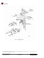
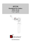
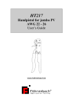
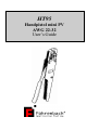
HT95
Handpistol mini PV
AWG 22-32
User’s Guide
CONTENTS
1. Introduction ..........................................................................................................3
1.1 Hand tool function ................................................................................................3
1.2 Physical description .............................................................................................3
1.3 Principles of operation..........................................................................................3
1.4 Specifications.......................................................................................................4
2. Operation .............................................................................................................5
2.1 Operating procedures ..........................................................................................5
2.2 Terminal inspection ..............................................................................................6
3. Troubleshooting ...................................................................................................8
4. Parts replacement procedure...............................................................................9
4.1 Anvil replacement.................................................................................................9
4.2 Wire and insulation barrel crimpers and tonker replacement ...............................10
4.3 Holding pin replacement ......................................................................................11
5. Crimp height adjustment ......................................................................................12
6. Parts.....................................................................................................................14
6.1 Spare parts...........................................................................................................14
6.2 Parts ordering information....................................................................................14
6.3 Hand tool repair policy .........................................................................................14
Instruction manual HT95
Date : August 2007
Documentrev. : 3
www.foehrenbach.be
Page : 2 / 15
1. INTRODUCTION
1.1. Hand Tool Function
The HT-95 is a manually operated hand tool designed for crimping loose piece
(individual) Mini PV™ terminals to various sizes of wire.
1.2. Physical Description
The major components which make up the HT-95 are identified in figure 1. These
include a frame, lever, tooling and tooling holders, and terminal holding pins. The heart
of the hand tool is the tooling. The tooling performs the crimping operation and is divided
into top and bottom component groups. The top group consists of those parts which
remain stationary with the frame. The bottom group contains those parts which move
with the lever. The HT-95 is equipped with tooling for crimping two different ranges of
wire sizes. These are identified as "A" and "B" on a plate affixed to the hand tool frame.
The "A" side tooling is for crimping terminals to wire sizes ranging from 28-32 AWG. The
"B" side tooling is used for wire sizes from 22-26 AWG.
1.3. Principles of Operation
The lever attaches to the lower tooling and provides the mechanical advantage to
generate the necessary crimping pressure. As the lever is closed, a ratchet mechanism
engages to prevent the lever from opening until the crimping cycle is complete.
When the lever is pulled closed, the lower tooling and terminal are pushed up against
the upper tooling. The crimp is formed between the wire and insulation barrel anvils and
the wire and insulation crimpers.
Once closed, the ratchet releases and allows a spring to pull the lever open.
Instruction manual HT95
Date : August 2007
Documentrev. : 3
www.foehrenbach.be
Page : 3 / 15
1.4. Specifications
When crimping the Mini PV™ to wires, the following parameters must be met.
Wire Length Requirements:
• Minimum ...................19.05 mm (0.75 in.)
• Maximum ..................As Required
Insulation Diameters of Wires:
• "A"Side(28-32AWG)..0.71-1.37mm
(0.028-0.054 in.) Dia.
• "B"Side(22-26AWG)..0.91-1.52mm
(0.036-0.060 in.) Dia.
Strip length of Insulation:
• Discrete and latch
Housing Applications.3.81-4.31 mm
(0.150-0.170 in.)
•
Rod Housing. ...........3.30-3.81 mm
Applications...............(0.130-0.150 in.)
Wire Barrel Crimp Height: (For All Applications)
• Single Wire 22-26 AWG or
Two Wires 26-28 AWG 0.81-0.86 mm
(0.032-0.034 in.)
•
Single Wire 28-32 AWG or
Two Wires 30-32 AWG 0.66-0.71 mm
(0.026-0.028 in.)
Insulation Barrel Crimp Height:
• Discrete Application . 2.84 mm (0.112 in.) Max.
• Latch and Rod Housing
Applications...............1.75 mm (0.069 in.) Max.
Mini PV™ Receptacles:
• loose Piece 22-32AWG
NOTE
Loose piece terminals have different part numbers than reeled terminals.
CAUTION
If the terminal and the tooling are not compatible, damage to the tooling could result. If
you wish to use a terminal with a part number other than the one that was ordered for
the HT95, check with your distributor or Föhrenbach Application Tooling NV to be sure
that the new terminal number is compatible with your hand tool.
Instruction manual HT95
Date : August 2007
Documentrev. : 3
www.foehrenbach.be
Page : 4 / 15
2. OPERATION
2.1 Operating Procedures
WARNING
To prevent hand injury, keep fingers from between the upper and lower tooling
and from between the lever and handle when closing hand tool.
1. Hold the hand tool so that the lever is on the left. With your index finger, push and
hold the terminal holder in its forward position. (See figure 2.)
2. Insert the disconnect (box) portion of the terminal, with "U" shaped barrels up, onto
the holding pin and against the pin shoulder. While holding the terminal against the
shoulder, release the terminal holder. This ensures that the terminal remains in
proper position while moving over the anvil.
3. While grasping the lever and the handle portion of the frame, insert a wire so that the
end of the insulation is centered between the wire barrel and the insulation barrel of
the terminal (see figure 3), then close the hand tool lever completely. This will crimp
the terminal to the wire(s).
Instruction manual HT95
Date : August 2007
Documentrev. : 3
www.foehrenbach.be
Page : 5 / 15
4. Release the lever to open the hand tool and remove the crimped terminal from the
holding pin by lightly pulling straight out on the wire.
CAUTION
The crimp height for this hand tool was factory adjusted. Any random changes to this
adjustment could cause a defective crimp or damage to the tooling.
2.2 Terminal Inspection
The crimped terminal should be inspected to ensure that the tooling is correctly aligned
and that the wire was correctly inserted. Make the following visual checks (see figure 4).
NOTE
If inspection of the crimped terminal reveals any defects, the terminal has not been
properly crimped and should be discarded,
-
Check that all wire strands were crimped within the wire barrel.
Check that the end of the wire insulation lies between the insulation and wire barrel.
Instruction manual HT95
Date : August 2007
Documentrev. : 3
www.foehrenbach.be
Page : 6 / 15
-
Check that the bellmouth(s) were formed correctly.
Check that the spring was not dislodged from the disconnect (box) portion of the
terminal.
Check that the ends of the wire strands form an angle not exceeding approximately
45°.
Check that the wire barrel seam is even and tightly closed.
Next, obtain a crimp height micrometer and measure the areas of the terminal shown in
figure 5. If the crimp heights do not meet the specifications listed in Section I, paragraph
D, refer to Section V for proper adjustment procedures.
Instruction manual HT95
Date : August 2007
Documentrev. : 3
www.foehrenbach.be
Page : 7 / 15
3. TROUBLESHOOTING
The troubleshooting information provided in the following chart will help isolate and
identify crimping problems.
Troubleshooting Chart, PV™ Receptacles HT -95
PROBLEM
1. Bellmouth(s) is deformed
or improperly positioned on
wire barrel.
POSSIBLE CAUSE
Terminal is not properly
positioned in crimping
area.
2. Disconnect (box) portion of Terminal is sticking in wire
barrel crimper.
terminal is bent down.
Tooling is broken or
cracked.
CORRECTIVE ACTION
Loosen the two 2-56 setscrews
on the side of the anvil holder
and reposition guide pins until
proper bellmouth(s) is
achieved.
Replace wire barrel crimper as
described in Section 2, paragraph 2.
3. The sides of the terminals
wire barrel are scored or
scratched.
Wire barrel crimper is
defective.
Replace wire barrel crimper as
described in Section 4, paragraph 2.
4. Flashings formed on the
bottom of the wire barrel are
unequal or abnormal.
Anvil is worn or broken.
Replace anvil as described in
Section 4, paragraph 1.
5. Insulation bulges between
wire and insulation barrels.
Wire is inserted too far into
terminal.
Position the end of the
insulation so that it lies midway
between the ends of the wire
barrel and the insulation barrel.
6. Insulation bulges around
insulation barrel.
Wire size or insulation
diameter is incorrect for
the terminal being used.
Refer to Section 1, paragraph
4 (specifications) for correct
insulation diameter
requirements.
Instruction manual HT95
Date : August 2007
Documentrev. : 3
www.foehrenbach.be
Page : 8 / 15
4. PARTS REPLACEMENT PROCEDURE
4.1 Anvil Replacement (see figure 6)
NOTE
Replace anvils when they show excessive wear or are cracked or chipped.
4.1.1. Removal
When removing the anvil, the terminal holder (10) and guide pins (15) must also be
removed. Prior to removal, note the position of the guide pins in the anvil holder, so that
they can be positioned as they were before removal: the flat on the guide pins must face
the setscrews (12) in the anvil holder (4).
1. Loosen the two 2-56 setscrews (12) in the anvil holder (4) and remove terminal
holder assembly (10).
2. Remove 4-40 cap screw (9) from the damaged anvil(s) (5) and (7), or (6) and (8).
3. Remove damaged anvil.
4.1.2. Installation
NOTE
When replacing tooling, be sure that the part number of the part being replaced is the
same as the number of the part that was removed.
1. Loosely install the new anvil(s) to the anvil holder (4) with the 4-40 cap screw (9).
2. Close hand tool completely; this aligns anvil to the crimper. Tighten the 4-40 cap
screw (9), and release the lever.
3. Re-install terminal holder (10) to the anvil holder (4) and tighten the two 2-56
setscrews (12).
4. Crimp a terminal to a proper-sized wire, and inspect the terminal as described in
Section II, paragraph B.
Instruction manual HT95
Date : August 2007
Documentrev. : 3
www.foehrenbach.be
Page : 9 / 15
4.2. Wire and Insulation Barrel Crimpers and Jonker Replacement
(see figure 6)
4.2.1. Removal
1. Loosen but do not remove at this time, the two 4-40 cap screws (9) that secure the
crimpers to the crimper holder (1).
2. Remove the 6-40 cap screw (13) from the crimper holder (1). Then remove the
spring retainer (21) and the crimper holder (1) with crimpers attached.
3. Remove the two tonker springs (19) and the two spring guides (20) from the hand
tool frame. This can be accomplished by tilting the hand tool down.
4. Remove the two 4-40 cap screws (9) that secure the crimpers to the crimper holder
(1).
5. Remove the crimpers (2 and 3) and tonkers (18) from the crimper holder. 6. Remove
the damaged crimper(s) (2 or 3). The top crimper is the wire barrel crimper (3).
4.2.2. Installation
NOTE
When replacing tooling, always be sure that the part number on the part(s) being
replaced is the same as the number of the part that was removed.
1. Place the insulation crimper (2) onto the flat side of the crimper holder (1). Place the
wire barrel crimper (3) on the insulation crimper (2) and install two 4-40 cap screws
(9) and loosely tighten.
2. Insert tonkers (18), with the top tabs facing outward, into the slots between the wire
and insulation crimpers.
3. Place and hold the crimper assembly into the hand tool on the same side as the anvil
holder (4). Make sure that the tonkers (18) go into the holes in the top of the hand
tool frame.
4. Place spring guides (20) into the holes in the top of the hand tool frame, then insert
the springs (19) into the holes so that the springs slip over the shoulder of the spring
guides.
5. Place spring retainer (21) over tonker springs (19). Make sure springs are fully
compressed, then loosely attach the spring retainer (21) and the crimper holder (1) to
the hand tool with a 6-40 cap screw (13).
Instruction manual HT95
Date : August 2007
Documentrev. : 3
www.foehrenbach.be
Page : 10 / 15
6. To align the tooling, close hand tool completely and hold it in its closed position.
Tighten the two 4-40 cap screws (9) to secure the crimpers to their holder. Then
tighten the 6-40 cap screw (13), which secures the crimper holder to the hand tool
frame.
7. Crimp a terminal to a proper-sized wire, and inspect the terminal as described in
Section II, paragraph B.
4.3.
Holding Pin Replacement (see figure 6)
NOTE
When holding pins (14) become bent, it is necessary to replace them.
4.3.1. Removal
NOTE
When removing the holding pin, the terminal holder (10) and guide pins (15) must also
be removed. Prior to removal. note the position of the guide pins (15) in the anvil holder,
so that they can be repositioned as they were before removal: the flat on the guide pin
must face the setscrew (12) in the anvil holder (4).
1. Loosen the two 2-56 setscrews (12) in the anvil holder (4). Then remove the terminal
holder assembly which includes the terminal holder (10), guide pins (15), "0" rings
(16), holding springs (17), and holding pins (14) attached.
2. Remove the two holding springs (17) and the guide pins (15) from the terminal
holder.
3. Loosen the two 2-56 setscrews (12) in the top of the terminal holder (10) which
secure the holding pins (14).
4. Using needle-nose pliers, remove both holding pins (14) by pulling straight out from
terminal holder (10). Discard the damaged holding pints).
4.3.2. Installation
CAUTION
Overtightening the two 2-56 setscrews (12) in the top of the terminal holder (10) can
flatten the holding pins (14), making them extremely difficult to remove.
1. Install two new holding pins (14) (0.025 in. square BergPin™ material 0.430 in. long)
into terminal holder (10) until pins are flush with the extended supports. Be sure that
a flat side of each pin is at right angles to the two 2-56 setscrew holes on top of the
terminal holder (10).
Instruction manual HT95
Date : August 2007
Documentrev. : 3
www.foehrenbach.be
Page : 11 / 15
2. Lightly tighten the two 2-56 setscrews (12) into the terminal holder (10) to secure the
holding pins (14).
3. Re-install the two guides pins (15), "0" rings (16), and the two holding springs (17).
4. Re-install the terminal holder (1 0) to the anvil holder (4), and tighten the two 2-56
setscrews (12) in the anvil holder (4) onto the flats of the guide pins (15).
5. Crimp a terminal to a proper-sized wire, and inspect the terminal as described in
Section II, paragraph B.
5. CRIMP HEIGHT ADJUSTMENT (see figure 6)
1. Loosen the two 2-56 setscrews (12) in the anvil holder (4). Remove terminal holder
assembly which includes the terminal holder (10), guide pins (15), "O" rings (16),
holding springs (17), and holding pins (14) attached.
2. Remove the 6-40 cap screw (13) which secures the anvil holder (4) to the adjustable
tool holder (11). Remove the anvil holder with anvils attached.
3. Insert a 3/32-inch Allen wrench into the hole in the adjustable tool holder (11) and
into the socket head setscrew. Turn screw to the right 1/4 turn to unlock the adjusting
collar.
4. Insert the turned-down end of the 3/32-inch Allen wrench (supplied with hand tool) or
a pin approximately 1/16-inch in diameter into one of the four holes in the adjusting
collar. Rotate the adjusting collar about 5 degrees to the right to increase the crimp
height by 0.002 inch, or to the left to decrease crimp height by 0.002 inch.
5. Re-install anvil holder (4) with anvils and loosely tighten the 6-40 cap screw (13).
6. Close hand tool completely so that the anvils align themselves to the crimpers. While
in the closed position, tighten the cap screw (13) to lock anvils into position. Open
the hand tool.
7. Re-install terminal holder assembly to the anvil holder (4) and tighten the two 2-56
setscrews (12) against the flats on the guide pins (15).
8. Crimp a terminal to a wire and recheck the wire barrel crimp height.
a. If crimp height meets specifications, remove terminal holder assembly and anvil
holder (4), then lock the adjusting collar by tightening the setscrew in the adjustable
tool holder (11). Reinstall terminal holder assembly and anvil holder as described in
steps 5 through 7 above.
Instruction manual HT95
Date : August 2007
Documentrev. : 3
www.foehrenbach.be
Page : 12 / 15
b. If crimp height does not meet specifications, close the hand tool one click (so that the
adjusting collar is visible) and rotate the adjusting collar as described in step 4. When
correct crimp height is attained, lock the adjusting collar by tightening the setscrew in
the adjustable tool holder (11). Reinstall terminal holder assembly and anvil holder
as described in steps 5 through 7 above.
Parts List for Figure 6. HT-95 Hand Tool Parts
Index
Part No
Description
No.
1
A-857 -5 Crimper holder
2*
104958-1 Insulation barrel crimper, 22-26 and 28-32 gauge wire
3*
104959-1 Wire barrel crimper, 22-26 and 28-32 gauge wire
4
102466-1 Anvil holder
5*
104914-A Insulation barrel anvil, 28-32 gauge wire
6*
104914-B Insulation barrel anvil, 22-26 awg wire
7*
104960-A Wire barrel anvil, 28-32 gauge wire
8*
104960-B Wire barrel anvil, 22-26 gauge Wire
9
Screw, cap, socket Hd, 4-40 NF x 0.37 in. Ig.
10
104961-1 Terminal holder
11
A-856-1
Tool holder, adjustable
12
Setscrew, socket Hd. 2-56 NF x 0.12 in. Ig.
13
Screw, cap, socket Hd. 6-40 NF x 0.50 in. Ig
14*
104756-1 Holding pin, (0.025" sq. Bergpin™ material 0.430" Ig.)
15
102468-1 Guide pin
16
"O" ring, 01-004
17
102470-1 Holding spring
18
104964-1 Tanker
19
A-1153
Spring tanker
20
A-11 55
Spring guide
21
104963-1 Spring retainer
* Recommended Spare Parts
Instruction manual HT95
Date : August 2007
Documentrev. : 3
Oty Per
1
1
1
1
1
1
1
1
4
1
4
2
2
2
2
2
2
2
2
1
www.foehrenbach.be
Page : 13 / 15
6. PARTS
6.1 Spare Parts
These are parts which F.A.Tooling NV considers practical for the user to stock for
replacement. Recommended spare parts for the hand tool are specified in bold type in
the parts list for figure 6.
6.2 Parts Ordering Information
To obtain replacement parts, contact F.A.Tooling NV, Krijgsbaan 128, 2640 Mortsel,
Belgium. Provide the description of the part, part number (if specified), quantity desired,
and also the hand tool model and serial number.
6.3. Hand Tool Repair Policy
The repair cost is according to expenses.
Instruction manual HT95
Date : August 2007
Documentrev. : 3
www.foehrenbach.be
Page : 14 / 15
The technical data in this publication has been carefully checked and assembled. No liability from inaccuracies or errors is assumed. The right to change
or improve this document without notice is reserved.
Instruction manual HT95
Date : August 2007
Documentrev. : 3
www.foehrenbach.be
Page : 15 / 15