1
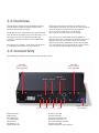
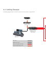
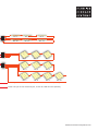
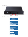
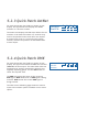
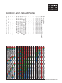
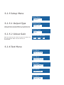
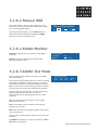
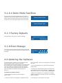
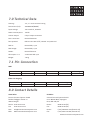
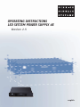
operating instructions
LED System power supply 4e
Version 2.5
english
Content
1.0
Overview
2.0
Connectivity
3.0
Installation
4.0
System Cabling
4.1
Cabling Examples
5.0
Menus
5.1
Menu Order
5.2
Menu Selection
5.2.1
Info
5.2.2
Manual Patch
5.2.3
Quick-Patch ArtNet
5.2.4
Quick-Patch DMX
5.2.5
Setup Menu
5.2.6
Test Menu
5.2.7
Factory Defaults
5.2.8
Error Messages
6.0
Updating the Software
7.0
Technical Data
7.1
Pin Connections
7.2
Contact Information
8.0
Declaration of EU conformity
www.schnickschnacksystems.com
1.0 Overview
The LED System Power Supply 4E (SPS4E) supplies
Schnick-Schnack-Systems’ Series B and Series C products with power and data.
Once again with these products each LED can be
individually controlled. The SPS 4E can also supply all
Series B products by Schnick-Schnack-Systems. Up to 20 x LED Tiles B or 8 m of LED Strips B25-250 can be connected to each output.
The SPS4E has four, independent 4 pin XLR outputs,
each of which can supply up to 10 x LED Tiles C, 17 x
LED Strips C25-250 or 17x LED Strips C50-500.
In Series C products the LEDs can be individually
controlled.
The SPS 4E can be controlled by either ArtNet or
DMX 512 data and is therefore compatible with most
lighting consoles and media servers. The control
signal can be freely patched across the four outputs.
It is also possible to use the SPS 4E as a stand-alone
unit, without a DMX or ArtNet control signal.
Each output can supply 1 x LED Panel C60 or C100,
2 x LED Band units or up to 8 m of LED Line.
2.0 Connectivity
The following connectors are located at the rear of the unit:
Fan Inlet
do not cover!
Clean regularly.
Fan Inlet
do not cover!
Clean regularly.
DMX-OUT
SD/MMC Ethernet
Out 4
Fuse 4
DMX In and Out:
ArtNet Input:
Mini USB Input:
2 x USB Output:
SD Card Slot:
LED Output 1-4:
Power Connector:
Out 3
Fuse 3
Fuse 2
DMX-IN
Out 2
Out 1
Fuse 1
Neutrik 5 pin XLR
Neutrik Ethercon
Reserved for future use
Reserved for future use
Used for software updates
Neutrik 4 pin XLR
Neutrik Powercon 100-250 V AC
Power connector
100-250 V AC
3.0 Installation
Examine the SPS 4E immediately after unpacking for any damage which may have occurred during
transit. A damaged unit should not be used under
any circumstances.
If the SPS 4E is moved from a cold to a warm environment, then a period of three hours should be allowed to pass before use, to allow for the
evaporation of any condensation, which may have
formed as a result of the temperature change.
If the SPS 4E is to be installed in a rack, care must
be taken to ensure that there is sufficient airflow
around both the front and back of the unit. The temperature of the surrounding air should not
exceed 35 °C.
The use of rails is recommended for rack-mounting,
to relieve strain on the front panel.
Connect the DMX In and (if necessary) Out cables,
followed by the LED outputs. Power-up the SPS 4E, by connecting the Neutrik Powercon plug. After approximately one second, the unit is ready for use.
Do not operate the SPS 4E in direct sunlight.
Do not use water or aggressive solvents to clean the SPS 4E, wiping with a damp cloth should be sufficient.
Heavy soiling may be removed using a mild
detergent.
4.0 System Cabling
Cabling of the system is very simple, although the following points should be considered:
Schnick-Schnack-Systems’ LED illuminants connect to each another using 4 pin PCB connectors, which are small, lightweight and ideal for this purpose.
The interface between the two types of cable is the XLR 4 Adapterboard: a small PCB which carries both
4 pin XLR and PCB connectors. It is designed to be
fitted to stage and set elements and provide a
rugged point of connection which will withstand
repeated use.
Cabling from the SPS 4E outputs makes use of XLR 4 pin cables, of the type commonly used in colour scroller systems with two wires for power and
a shielded pair for data.
Each output of the SPS 4E will drive up to 512 channels of DMX i.e.:
10 x LED Tiles C or 17 x LED Strips C25-250 or 32 x LED Strips with Intelligenz or 1 x LED Panel C60 or
2 x LED Band C100.
Please note: The length of the 4 pin XLR cable between the SPS 4E and the Adaptorboard should not exceed
20 m.
Each output of the Adaptorboard will drive up to 3 A power, i.e.:
10 x LED Tiles B or 10 x LED Tiles C or 16 x LED Strips B25-250 with Intelligenz.
Please note: The total length of PCB cable connected to an Adaptorboard output should not exceed 6 m,
including the loopback.
www.schnickschnacksystems.com
4.1 Cabling Example
The following diagram offers an overview of various connection options, using the SPS 4E.
shift
edit
quit enter
down
up
pixel-gate
www.schnickschnacksystems.com
Pixel Gate
Ethernet Switch
(Business Class)
Schnick
Schnack
Systems
om
www.schnickschnacksystems.c
shift
edit
LED-PSU 4
Version 1.7
quit enter
down
up
led systemnetzteil 4e
System Power Supply 4E
(Artnet Converter,
DMX Router and
Power Supply)
Alternativ:
DMX Source
CAT 6 Cable
DMX XLR-5 Pol Cable
Power and DMX, XLR-4 Pol Cable
Power and DMX, PCB Link Cable
No. 1
No. 2
No. 9
No. 10
No. 11
No. 17
No. 1
No. 2
No. 3
No. 4
No. 5
No. 6
No. 7
No. 8
No. 9
No. 10
Third exit just as with maximally 6 A, and/or 512 DMX channels provably.
Fourth exit just as with maximally 6 A, and/or 512 DMX channels provably.
www.schnickschnacksystems.com
5.0 Menus
Shift Edit
Down
Up
Quit Enter
5.1 Menu Order
Welcome to
Systemnetzteil 4E
IP x.xxx.xx.xx
Main Menu:
Info
Main Menu:
Quickpatch ArtNet
Main Menu:
Quickpatch DMX
Main Menu:
Setup Menu
Main Menu:
Test Menu
Main Menu:
Factory Defaults
x °C
v 2.5
5.2 Menu Selection
To change mode, press the QUIT button, the display
will show Change Mode? Confirm the action by
pressing the ENTER button or cancel by pressing the
QUIT button again. Use the UP and DOWN buttons to
select the desired mode. Confirm selection by pressing the ENTER button or press the QUIT button
to return to the most recently used mode.
Change Mode?
Quit
Enter
5.2.1 Info
This mode displays the unit type and installed
software version.
Welcome to
Systemnetzteil 4E
IP x.xxx.xx.xx
x °C
v 2.5
5.2.2 Manual Patch
When changing from the Quick Patch mode into the
Manual Patch mode the following display is shown:
This mode offers the user the opportunity to
overwrite the DMX channels set by the Quick Patch
mode with channels of their own choice. Please
note that as this operation is irreversible, SHIFT and
ENTER must be pushed together, in order to confirm
the channel selection, otherwise press QUIT to exit
the mode.
Overwrite Patch with Quick Patch?
Quit
Shift+Enter
Out:
Ch:
Universe: DMX
Type: FIX Val: OFF
1
Setting values in Manual Patch mode:
Use the OUT field to select the output to be patched
(1-4). Use the CH filed to assign a DMX start address
to the selected. In the TYPE field select INT to allow
an output level to be set manually. Select DMX to
allow control of the output via DMX.
www.schnickschnacksystems.com
5.2.3 Quick Patch ArtNet
For each output two data fields are shown on the
display. The uppermost field displays the ArtNet universe as a decimal number.
Universe
Start-Ch:
Out
1
DMX: NONE
Start-Ch:
Combine:
Out
1
0
1
Out
2
1
1
Out
3
2
1
Out
4
3
1
The lower field displays the DMX start address for the
universe in the data field above it (a universe may
need to be patched across more than one output).
A control check mark in a square by each output
number, denotes the presence of valid ArtNet data at that output.
5.2.4 Quick Patch DMX
For each output two data fields are shown on the
display. The upper field shows the DMX start channel
(start CH:) for that output. The lower field offers the
opportunity to combine subsequent channels into
regularly repeating groups. Use the EDIT button to
select the required field.
The DMX field shows the status of the incoming
DMX signal. NONE shows that no DMX signal is being
received. GOOD shows that a valid DMX signal is
being received.
The table on the following page shows the various
repeat and combine options available via the menu
system.
1
Out
2
1
Out
3
1
Out
4
1
OFF OFF OFF OFF
Combine and Repeat Modes
OFF - no combine
OFF - keine Kombination
ALL3- alle
LED-Platinen
ALL - all LED boards are steered by
DMX
channelswerden durch 3
DMX-Kanäle gesteuert
C2 - immer 2 Platinen werden verbunden
C 2 - always 2 plates are interconnected
C3 - immer 3 Platinen werden verbunden
C 3 - always 3 plates are interconnected
C4 - immer 4 Platinen werden verbunden
C 4 - always 4 plates are interconnected
C5 - immer 5 Platinen werden verbunden
C 5 - always 5 plates are interconnected
C6 - immer 6 Platinen werden verbunden
C 6 - always 6 plates are interconnected
C7 - immer 7 Platinen werden verbunden
C 7 - always 7 plates are interconnected
C8 - immer 8 Platinen werden verbunden
C 8 - always 8 plates are interconnected
C9 - immer 9 Platinen werden verbunden
C 9 - always 9 plates are interconnected
C10 - immer 10 Platinen werden verbunden
C 10 - always 10 plates are interconnected
R2 - jede zweite Platine wird miteinander
R3 - jede dritte Platine wird miteinander
R 2 - each second plate is interconnected
verbunden
R4 - jede vierte Platine wird miteinander
R 3 - each third plate is interconnected
verbunden
R5 - jede fünfte Platine wird miteinander
R 4 - each fourth plate is interconnected
verbunden
R6 - jede sechste Platine wird miteinander
verbunden
R 5 - each fifth plate is interconnected
R7 - jede siebte Platine wird miteinander
verbunden
R 6 - each sixth plate is interconnected
R8 - jede achte Platine wird miteinander
verbunden
R 7 - each seventh plate is interconnected
R9 - jede neunte Platine wird miteinander
verbunden
R 8 - each eighth plate is interconnected
R10 - jede zehnte Platine wird miteinander
verbunden
R 9 - each ninth plate is interconnected
verbunden
R 10 - each tenth plate is interconnected
www.schnickschnacksystems.com
5.2.5 Setup Menu
Setup Menu:
Output
5.2.5.1 Output Type
Switch between standard DMX 512 or S3 DMX for the
enterprise of the LED tiles C25 or LED panels C60-25.
Output Type:
DMX 512
Output Type:
5.2.5.2 Colour Gain
With this function the colors red, green and blue can
be made darker. With 255 this function is
deactivated.
Gain
Colour Gain (off: 255)
R: 255
G: 255
B: 255
5.2.6 Test Menu
Test Menu:
Manual RGB
Test Menu:
ArtNet Monitor
Test Menu:
ArtNet Test TX
Test Menu:
Demo Slow
Test Menu:
Demo Fast
5.2.6.1 Manual RGB
This mode allows a static, single colour to be set
across all connected illuminants, without the need
for an incoming DMX signal.
Manual Color Mode
R:
0
G:
0
B:
0
As with the other modes, use the EDIT button to
select the required field and the UP and DOWN
buttons to set the required values.
5.2.6.2 ArtNet Monitor
Universes indicates the first and last sent ArtNet
universe.
Monitor indicates, with which frequency the
adjusted universe sends.
ArtNet Monitor
0.0
Universes
0 0.0 Hz
Monitor
5.2.6.3 ArtNet Test Mode
In this mode the SPS 4E will function as an ArtNet
data transmitter.
This function was implemented as a means of testing
the cables and Ethernet switches used in a system
without the need for an external ArtNet data source.
While in this mode, the SPS 4E will perform no other
functions and no control over LEDs will be possible.
ArtNet Test Mode
Ton
Toff
#uni
0.50 1.00 255
State
Off
In this mode, the SPS 4E sends a strobe signal over
ArtNet, switching all channels on and off
simultaneously. The following parameters can be
adjusted:
Ton: The duration of the On-pulse of the strobe
impulse (in seconds).
Toff: The duration of the Off-pulse of the strobe
impulse (in seconds).
#uni: The number of the ArtNet universe, over which
data is being sent.
In this mode, the SPS 4E will default to the last-used
universe.
The STATE field display, in real time, wheter an ON or
OFF pulse is being sent.
www.schnickschnacksystems.com
5.2.6.4 Demo Mode Fast/Slow
In this mode all connected LEDs will run a preset
sequence at one of two speeds selected by the user.
Please note that separate SPS 4E units running this
mode will not run synchronization with each other.
Demo Mode Slow
Demo Mode Fast
5.2.7 Factory Defaults
The equipment puts back to factory settings.
Restore Factory Defaults?
Quit
Shift+Enter
5.2.8 Error Message
If one of the fuses protecting the outputs should fail,
the display will flash and show the following type of
message.
Output Error
BAD O.K. O.K.O.K.
Fuse:
Out
1
Out
2
Out
3
Out
4
6.0 Updating the Software
The SPS 4E system software can be updated easily
with the latest version, using an SD Card.
New software versions keep products up to date with
the latest features and are available for download
from our website at www.schnickschnacksystems.
com. Please read the readme.txt file, for details of
how to format the software correctly onto an
SD Card.
To update the software version:
to be uploaded, into the SC Card slot on the rear of
the unit.
3. Turn the SPS 4E back on, bye reconnecting the
power cable.
4. The SPS 4E automatically detects and loads the
new software version. The software is loading, the
display will show a message saying: „Please wait“.
1. Turn off the SPS 4E by disconnecting the
power cable.
5. When the installation is complete, the display
shows the welcome message and the new software
version number.
2. Insert the SD Card, carrying the software version
6. The SPS 4E is now ready to use again.
7.0 Technical Data
Housing: 19“, 2 U rack-mounted casing
Dimensions (mm): 483x88x430(WxHxD)
Input voltage: 100-250 V AC, 50/60 Hz
Power comsumption: 700 VA
Current output: 6 A per output maximum
Main connector:
Neutrik Powercon
Data protocol: DMX 512 A-1990 USITT, isolated and protected
DMX in:
Neutrik XLR, 5 pin
DMX trough:
Neutrik XLR, 5 pin
ArtNet: Neutrik Ethercon
LED outputs 1-4:
4 x Neutrik XLR 4 pin
Weight:
1.8 kg
7.1 Pin Connection
DMX:
1
2
3
4
5
Housing
Data GND
Data -
Data +
n/c
n/c
n/c
1
2
3
4
Housing
GND
Data -
Data +
+ 24 V
n/c
XLR 4-Pol-Ausgang:
8.0 Contact Details
Head Office:
UK Office:
Schnick-Schnack-Systems GmbH
Mathias-Brüggen-Straße 79
50829 Cologne
Schnick-Schnack-Systems GmbH
8-11 Willow Walk, Orpington
Kent, BR6 7AA, UK
Phone: 0221/99 20 19-0
Fax:
0221/99 20 19-22
Phone: Fax:
0844/43 95 (UK)
0844/43 96 (UK)
Mail:
Web:
Phone: Fax:
(+44) 1689/853 749 (Outside UK)
(+44) 5601/525798 (Outside UK)
[email protected]
www.schnickschnacksystems.com
www.schnickschnacksystems.com
8.0 EC-Declaration of conformity
9.0 Declaration of EU conformity
EC-Declaration of conformity
I hereby declare that the product
LED-Beleuchtungssystem bestehend aus „LED-Systemnetzteil 4E“, „LED-Kachel C“,
„LED Streifen C25“, „LED Pnael C60“, „LED-Band C100“, „LED Streifen B“ mit „Intelligenz“ und Verkabelung nach Bedienungsanleitung
(Name of product, type or model, batch or serial number)
meets the essential requirements referred to in Article 3 of the Council Directive 99/5/EC.
The following harmonized standards have been applied:
EN 60950-1:2003
EN 55015:2000
MANUFACTURER or AUTHORIZED REPRESENTATIVE:
Schnick-Schnack-Systems GmbH
Heinrich-Pesch-Strasse 14
50739 Koeln
Germany
Tel:
Fax:
+49 221 992019-0
+49 221 992019-22
Koeln, January 2nd 2008
(Place, Date of issue)
(Signature)
Dipl.Ing.(FH) Erhard Lehmann
(Name in block letters)
Page 19
www.schnickschnacksystems.com